EP3337617B1 - High efficiency conical mills - Google Patents
High efficiency conical mills Download PDFInfo
- Publication number
- EP3337617B1 EP3337617B1 EP16838617.5A EP16838617A EP3337617B1 EP 3337617 B1 EP3337617 B1 EP 3337617B1 EP 16838617 A EP16838617 A EP 16838617A EP 3337617 B1 EP3337617 B1 EP 3337617B1
- Authority
- EP
- European Patent Office
- Prior art keywords
- sidewall
- openings
- screen
- open area
- area percentage
- Prior art date
- Legal status (The legal status is an assumption and is not a legal conclusion. Google has not performed a legal analysis and makes no representation as to the accuracy of the status listed.)
- Active
Links
Images




Classifications
-
- B—PERFORMING OPERATIONS; TRANSPORTING
- B02—CRUSHING, PULVERISING, OR DISINTEGRATING; PREPARATORY TREATMENT OF GRAIN FOR MILLING
- B02C—CRUSHING, PULVERISING, OR DISINTEGRATING IN GENERAL; MILLING GRAIN
- B02C18/00—Disintegrating by knives or other cutting or tearing members which chop material into fragments
- B02C18/06—Disintegrating by knives or other cutting or tearing members which chop material into fragments with rotating knives
- B02C18/062—Disintegrating by knives or other cutting or tearing members which chop material into fragments with rotating knives with rotor elements extending axially in close radial proximity of a concentrically arranged slotted or perforated ring
-
- B—PERFORMING OPERATIONS; TRANSPORTING
- B02—CRUSHING, PULVERISING, OR DISINTEGRATING; PREPARATORY TREATMENT OF GRAIN FOR MILLING
- B02C—CRUSHING, PULVERISING, OR DISINTEGRATING IN GENERAL; MILLING GRAIN
- B02C23/00—Auxiliary methods or auxiliary devices or accessories specially adapted for crushing or disintegrating not provided for in preceding groups or not specially adapted to apparatus covered by a single preceding group
- B02C23/08—Separating or sorting of material, associated with crushing or disintegrating
- B02C23/16—Separating or sorting of material, associated with crushing or disintegrating with separator defining termination of crushing or disintegrating zone, e.g. screen denying egress of oversize material
-
- B—PERFORMING OPERATIONS; TRANSPORTING
- B02—CRUSHING, PULVERISING, OR DISINTEGRATING; PREPARATORY TREATMENT OF GRAIN FOR MILLING
- B02C—CRUSHING, PULVERISING, OR DISINTEGRATING IN GENERAL; MILLING GRAIN
- B02C23/00—Auxiliary methods or auxiliary devices or accessories specially adapted for crushing or disintegrating not provided for in preceding groups or not specially adapted to apparatus covered by a single preceding group
- B02C23/08—Separating or sorting of material, associated with crushing or disintegrating
- B02C23/16—Separating or sorting of material, associated with crushing or disintegrating with separator defining termination of crushing or disintegrating zone, e.g. screen denying egress of oversize material
- B02C2023/165—Screen denying egress of oversize material
Definitions
- This disclosure relates to conical mills used to reduce the particle size of granular materials. More specifically, this disclosure relates to the conical screens used in such conical mills, which include a hole pattern that varies from the top to the bottom of the sidewall for narrower particle size distributions, reduced heat generation and increased capacity.
- the disclosed conical mills may be cleaned without disassembly and the disclosed conical mills feature lubricant-free gearboxes, which reduce the risk of product contamination.
- Conical mills are widely used in the production of powders used in pharmaceuticals, food and cosmetics. Powders are typically manufactured as solid or granular materials before being size-reduced into the desired final powder particle size distribution or form. For example, the manufacture of pharmaceutical tablets requires milling (or size-reduction) of the granular material to a milled powder that can easily flow and be pressed into a tablet.
- Conical mills of the prior art include an impeller or rotor disposed within a conical or frusto-conically-shaped classifying screen located between an input and an output, all of which is disposed within a milling chamber. See, e.g., U.S. Patent Nos. 4,759,507 , 5,282,579 , 5,330,113 and 5,607,062 , all commonly assigned to Quadro Engineering.
- These conical mills employ various screen and impeller combinations to reduce the particle size of the incoming granular material. The choice of the screen and impeller combination depends on the desired particle size distribution (PSD) and the type of granular product being processed. While the openings of each screen are of a uniform size and shape, various screens are available with openings of different sizes and shapes that help determine the PSD of the milled powder product.
- PSD particle size distribution
- Prior art screens used by various milling technologies have the same size openings (holes) and open area percentage throughout the entire surface of the screen, as they are made from blanks by punching, chemically etching or laser cutting the openings.
- these screens For conical mills, these screens have about a 60-degree profile (larger diameter at the top, tapering down towards the bottom), with the impeller matching the profile of the screen.
- the impeller rotates, the velocity of the impeller arms is higher near the wider top of the screen than at the narrower bottom of the screen. As a result, the energy imparted to the solid product or powder is not consistent from the top to the bottom of the screen.
- conical mills must be capable of full sanitization. Further, because the production of powders may create an inhalation hazard, and a particularly acute hazard when it comes to some pharmaceutical compounds, the milling chamber must provide adequate containment of the milled powder and any dust created by the milling process. Because of the potentially hazardous nature of some powders, the pharmaceutical industry is trending toward equipment that does not require manual cleaning, but rather equipment that can be cleaned automatically without operator exposure to the milled powder or dust, and without the need to move the equipment, which is also characterized as "clean-in-place" or CIP designs. Therefore, any improved conical mill should also be a CIP design.
- conical mills can generate substantial noise during operation, which requires operators to wear ear protection. With a manufacturer operating several or dozens of conical mills in one area of facility, noise generation from conical mills can be problematic. Hence, improved conical mills that generate less noise are in demand.
- Cigar Patent 202981523 teaches a filtering assembly for a juicer, comprising a body having a motor and a cutter at the top of the motor. A screen is outside the cutter.
- the screen has openings on its trapezoid sidewall, wherein the radius of the openings increases from bottom of the sidewall to the top of the sidewall; or the screen has multi-layered openings on its trapezoid sidewall.
- the openings have different radiuses on different layers. The density and radius of the openings increase from the bottom of the sidewall to the top of the sidewall.
- U.S. Patent No. 4,759,507 teaches a series of screens for use with a size reduction machine have a tapered apertured wall formed into a frusto-conical shape, with an open wide end and a narrow closed end. All screens of a particular series have a cylindrical section, the same interior depth, outside diameter and angle of the tapered wall. Despite variations in the material wall thickness, screens of the same series are interchangeable on a size reduction machine and the gap can remain constant without any adjustment to the impeller. Further, a size reduction machine has means external to the machine providing for infinite adjustments to the gap. With previous machines, each time that a screen of a different thickness was used, it was necessary to make an adjustment to the gap in order to maintain the same gap. Further, when an adjustment to the gap is required, that is accomplished by removing the screen and impeller from the machine and inserting spacers onto the shaft.
- this application discloses improved conical mills with one or more improvements in the form of redesigned screens, impellers, housings and/or gearboxes.
- the disclosed screens and/or the disclosed screens in combination with the disclosed impellers provide narrower PSDs, reduced heat generation and improved throughput.
- the disclosed housings and gearboxes of the disclosed conical mills eliminate or substantially reduce sound generation, the possibility of product contamination from the gearbox and the disclosed conical mills may be cleaned in place (CIP design).
- the top or upper portion of the screen has more openings or a greater open area percentage because the higher rotational speed of the impeller at the top of the screen requires less exposure of the powder to the impeller and, hence, the need for a higher open area percentage and shorter spacings between openings.
- milling forces seen by the powders inside the milling chamber are evenly distributed across the entire height or length of the screen, resulting in more particles having similar sizes once milled and therefore narrower PSDs.
- the redesigned screen opening (hole) patterns increase the open area percentage near the top of the sidewall by up to 50% over traditional conical screens, thereby reducing the residence time inside the milling chamber, reducing heat generation and improving capacity.
- the disclosed conical mills incorporate an impeller with a captured O-ring configuration and redesigned impeller cross arms ensuring full cleaning coverage of all powder-contact surfaces without the need to open the equipment to clean manually. Furthermore, complete containment of powders and cleaning solution is achieved inside the milling chamber via two O-rings, located above and below the screen's contact points with the feed chute and the housing. This ensures that powders during milling are only present in the internal contact surface areas and cleaning solutions cannot escape or be trapped in crevices after a cleaning cycle.
- the disclosed conical mill employs non-metallic gears inside the gearbox, eliminating the need to use grease to lubricate.
- the gearbox is isolated from the product contact zone with the use of seals. These seals make positive contact with the rotating shaft to ensure that no product can penetrate the gearbox and no grease/lubricant can escape the gearbox and contaminate the powders being milled.
- the gearbox may employ non-metallic composite gears.
- the gearbox disclosed herein may house high strength composite material gears, which can be operated reliably and consistently without the need to add any lubrication or grease. Therefore, even if a shaft seal is inadvertently compromised, the product will not be contaminated from the gearbox. In the pharmaceutical and food industries where a large percentage of these machines are sold, eliminating this potential source of contamination is deemed critical. In contrast, prior art gearboxes currently used for size-reduction apparatuses employ steel, stainless steel or bronzed gears - with FDA approved lubricant. Nevertheless, should this lubricant contaminate a batch of product, the batch will need to be discarded
- a screen for a mill in one aspect, includes a tapered sidewall having a wider top and a narrower bottom.
- the sidewall includes a plurality of openings that may be of a uniform size. Each opening is separated from adjacent openings by spacing distances. The spacing distances at the top of the sidewall being shorter than the spacing distances at the bottom of the sidewall. As a result, the open area percentage at the top of the sidewall is greater than the open area percentage at the bottom of the sidewall.
- a mill in any one or more of the embodiments described above, includes a housing that accommodates a frusto-conically shaped screen that includes a tapered sidewall having a wider top and a narrower bottom.
- the sidewall includes a plurality of openings of a uniform size. Each opening is separated from adjacent openings by a spacing distance. The spacing distances at the top of the sidewall being shorter than the spacing distances at the bottom of the sidewall (and, consequently, the open area percentage at the top of the sidewall is greater than the open area percentage at the bottom of the sidewall).
- the sidewall accommodates an impeller mounted coaxially within the sidewall of the screen.
- the impeller includes a lower base disposed at the bottom of the sidewall of the screen and the lower base may be connected to an output shaft that extends through the bottom of the sidewall of the screen.
- the base connects to at least one milling member that extends from the top to the bottom and along the sidewall.
- the output shaft of the impeller connects to an output gear.
- the output gear meshes with an input gear.
- the input gear may connect to an input shaft, which may connect to a motor.
- non-metallic composite materials may be used to fabricate the input gears.
- a method for size-reducing a flowable solid material may include providing a mill that includes a housing that accommodates a screen between a top and a bottom of the housing.
- the screen includes a frusto-conically shaped sidewall having a wider top and a narrower bottom.
- the sidewall screen includes a plurality of openings of a uniform size. However, each opening is separated from adjacent openings by spacing distances. The spacing distances between openings at the top of the sidewall of the screen are shorter than the spacing distances between the openings at the bottom of the sidewall of the screen (and, consequently, the open are percentage at the top of the screen exceeds the open area percentage at the bottom of the screen).
- the sidewall accommodates an impeller mounted coaxially within the sidewall.
- the impeller comprises at least one milling member that extends parallel to the sidewall from the top to the bottom of the sidewall.
- the method further includes rotating the impeller, delivering flowable solid material through the top of the housing and through the top of the sidewall of the screen, pressing the flowable solid material through the openings in the sidewall of the screen with the rotating impeller to produce size-reduced material, and collecting the size-reduced material.
- an open area percentage provided by the openings in the sidewall of the screen is greater at the top of the sidewall of the screen than at the bottom of the sidewall of the screen.
- the sidewall of the screen is frusto-conically shaped.
- the openings in the sidewall of the screen have a shape selected from the group consisting of round, square and rectangular.
- the sidewall, at each opening, includes an inwardly extending dimple or rasp.
- the sidewall of the screen includes a total surface area interrupted by the openings.
- the sidewall also includes an upper section, an upper middle section, a lower middle section and a lower section.
- the openings in the upper section provide an open area percentage ranging from about 30% to about 50% of the total surface area of the sidewall in the upper section
- the openings in the upper middle section provide an open area percentage ranging from about 25% to about 45% of the total surface area of the sidewall in the upper middle section
- the openings in the lower middle section provide an open area percentage ranging from about 20% to about 40% of the total surface area of the sidewall in the lower middle section
- the openings in the lower section provide an open area percentage ranging from about 15% to about 35% of the total surface area of the sidewall in the lower section.
- the sidewall of the screen includes a total surface area interrupted by the openings that accumulatively provide an open area percentage.
- the open area percentage may range from about 30% to about 50% at the top of the sidewall while the open area percentage may range from about 15% to about 35% at the bottom of the sidewall and the openings disposed between the top and bottom of the sidewall may provide an open area percentage ranging from less than about 40% to greater than about 25%.
- At least part of the output shaft, the output shaft and at least part of the input shaft are disposed within a gearbox.
- the gearbox is sealably connected to the housing. Further, the gearbox contains no lubricant.
- the impeller includes a lower base disposed at the bottom of the sidewall of the screen, which connects to an output shaft that extends through the bottom of the sidewall of the screen.
- the base connects to at least one milling member that extends from the top to the bottom of the sidewall of the screen.
- the output shaft connects to an output gear.
- the output gear meshes with an input gear.
- the input gear connects to an input shaft and the input shaft connects to a motor.
- the input gears are fabricated from non-metallic composite materials.
- the output shaft and at least part of the input shaft are disposed within a gearbox, which sealably connects to the housing of the conical mill.
- the gearbox includes no lubricant because the use of non-metallic composite materials for the input gears eliminates the need for lubricant.
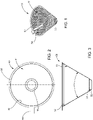
- FIGS. 1-3 generally illustrate the configuration of a frusto-conical screen 50 for use in the conical mill 62 illustrated in FIGS. 23-28 .
- the screen 50 includes a tapered sidewall 51 that includes a wider top 52 and a narrower bottom 53.
- the tapered sidewall 51 includes a plurality of openings or openings 54 that are of a uniform size. Typically, the angle ⁇ between diametrically opposed portions of the tapered sidewall 51 is about 60°, but the exact geometry of the screen 50 may vary as will be apparent to those skilled in the art.
- the bottom 53 connects to another frusto-conical bottom section 55 for receiving the lower end 56 of the impeller 57 illustrated in detail in FIGS. 17-20 .
- the screen 50 also includes an outer flange 58 for supporting the screen 50 within the housing 61 of the conical milling 62 as illustrated in FIGS. 24-25 .
- the screen 50 may also include a tab 63 for ease of handling.
- FIG. 4 illustrates a partial top view of another disclosed screen 50a that also includes a tapered sidewall 51a that includes a top 52a and a bottom 53a.
- the screen 50a also includes a bottom section 55a for receiving the lower end 56 of the impeller 57 and a flange 58a for supporting the screen 50a at the groove 101 at the top of the housing 61 of the conical mill 62 ( FIGS. 24-25 and 36 ).
- the top view provided by FIG. 4 also reveals that the screen 50a includes four distinct sections including an upper section 64 disposed inside the top 52a of the tapered sidewall 51a, an upper middle section 65, a lower middle section 66 and a lower section 67.
- the lower section 67 is disposed between the bottom 53a of the tapered sidewall 51a and the lower middle section 66, which is disposed between the upper middle section 65 and lower section 67, which is disposed between the upper section 64 and the lower middle section 66 as shown in FIG. 4 .
- the four sections 64-67 may have different hole patterns, different spacing distances between openings 54 and different open area percentages as illustrated in greater detail in FIGS. 6-8 .
- Each section includes a plurality of openings 54 that may be of a uniform size. However, the spacing distances between the openings 54 vary from the upper section 64 to the lower section 67.
- the upper section 64 engages to the upper portions of the milling members 71, 72 of the impeller 57, which travel at a faster rotational velocity than lower portions of the milling members 71, 72. Therefore, the upper sections 64 of the screen 50a are exposed to a greater amount of energy from the impeller 57 while the lower section 67 of the screen 50a is exposed to a lower amount of energy from the rotating impeller 57.
- the energy delivered by the rotating impeller 57 decreases along the tapered sidewall 51a from the upper section 64 to the bottom section 67.
- the lower section 67 has fewer openings 54, longer spacings between openings 54 and a lower open area percentage.
- the spacing distance D 1 of the upper section 64 is shorter than the spacing distance D 2 of the upper middle section 65 illustrated in FIG. 6 , which is shorter than the spacing distance D 3 of the lower middle section 66 as illustrated in FIG. 7 and which is shorter than the spacing distance D 4 of the lower section 67 as illustrated in FIG. 8 .
- the upper section 64 has the highest open area percentage and the smallest spacing distance D 1 between openings 54 while the lower section 67 has the lowest open area percentage and the greatest spacing distance D 4 between adjacent openings 54.
- the angle ⁇ between the openings 54 for the hole patterns illustrated in FIGS. 5-8 may be about 60° although the angle ⁇ may vary as will be apparent to those skilled in the art.
- the open area percentage for the four distinct sections 64, 65, 66, 67 of the screen 50a may range from about 30% to about 50% for the upper section 64, from about 25% to about 45% for the upper middle section 65, from about 20% to about 40% for the lower middle section 66 and from about 15% to about 35% for the lower section 67.
- the open area percentages as well as the spacing distances D 1 -D 4 may vary greatly, as will be dependent on the material being milled, the desired PSD, operating conditions and other factors as will be apparent to those skilled in the art.
- the open area percentages for the sections 64-67 may be 40%, 35%, 30% and 25% respectively.
- yet another screen 50b is disclosed that includes the same structural features as the screens 50, 50a, including the flange 58b, bottom section 55b, and tapered sidewall 51b, which extends from a top 52b to a bottom 53b.
- the screen 50b features a gradual decrease in open area percentage (or increase in spacing distances) from the top 52b to the bottom 53b.
- the open area near the top 52b of the tapered sidewall 51b may range from about 30% to about 50%, depending upon the material being processed, the size of the openings 54, the desired PSD, etc.
- the open area percentage near the bottom 53b may range from about 15% to about 35%, depending upon a myriad of factors that will be apparent to those skilled in the art. In one non-limiting example, the open area percentage may be about 40% near the top 52b of the tapered sidewall 51b and about 25% at the bottom 53b of the tapered sidewall 51b.
- each opening 54 includes a rasp element 73 for enhanced grinding/milling of the flowable material processed by the conical mill 62.
- the open area percentage decreases from the top 52c to the bottom 53c of the tapered sidewall 51c while the spacing distances increase from the top 52c to the bottom 53c.
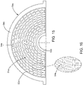
- FIGS. 13-16 illustrate two additional screens 50d, 50e wherein the openings 54d, 54e are square and rectangular respectively as opposed to the circular openings 54 illustrated in FIGS. 1 , 5-8 and 10 .
- the general concept remains the same; the open area percentage is highest towards the tops 52d, 52e of the tapered sidewalls 51d, 51e, and the open area percentage is the smallest at the bottoms 53d, 53e of the tapered sidewalls 51d, 51e, respectively.
- the disclosed impeller 57 includes a recess 75 for capturing an O-ring 76 that seals the internal cavity 77 against the output shaft 78 of the gearbox 80 (see FIGS. 29-32 ).
- Cross arms 81, 82 connect the milling members 71, 72 to the central shaft 83 of the impeller 57.
- the shaft 83 of the impeller 57 may couple to the output shaft 78 of the gearbox 80 using a key and slot connection or other suitable means of detachable attachment.
- the lower end 56 of the impeller 57 fits snuggly within the bottom sections 55, 55a, 55b, 55c, 55d, 55e and the lower end 56 of the impeller 57 connects to the milling members 71, 72 at an outwardly extending lip 83a that rides on the junction of the bottoms 53, 53a-53e of the tapered sidewalls 51, 51a-51e and the bottom sections 55, 55a-55e of the screens 50, 50a-50e. See, e.g., FIGS. 3 , 18 and 22 .
- the gearbox 80 also includes a seal assembly 84 that further prevents any cross-contamination between the gearbox 80 and the milling chamber 85 provided by the housing 61 (see FIGS. 35-41 ).
- the gearbox 80 may include an output gear 87 that connects to the output shaft 78 and that meshes with an input gear 88.
- the input gear 88 couples to an input shaft 89, which couples to a motor 91, which can be seen in FIGS. 23 and 26 .
- the input gear 88 is fabricated from non-metallic composite materials.
- non-metallic composite materials from which the input gear 88 is fabricated may be of the type that does not require lubrication.
- the gearbox 80 may be a lubricant free gearbox 80 with, in addition to the seal assembly 84 and captured O-ring 76, prevent contamination of lubricant or other materials from the gearbox 80 into the milling chamber 85.
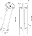
- the input shaft 89 passes through a gearbox housing 90 that sealably couples to a spindle housing 92 ( FIG. 34 ) that accommodates a spindle 93 which, in turn, connects to the motor 91 illustrated in FIGS. 23 and 26 .
- the O-ring 115 seals the spindle housing 92 to the gearbox housing 90.
- FIG. 24 illustrates a collection receptacle 100 that, as will be apparent to those skilled in the art, may be a bin, a container or a conveying system, such as a pneumatic conveying system.
- FIGS. 23-28 illustrate one suitable conical mill 62.
- a supporting stand 94 may include wheels 95 and an upright support 96 for supporting a control panel 97.
- the stand 94 may also include an additional upright support 98 for supporting the motor 91, the spindle housing 92 and the housing 61 of the conical mill 62.
- a feed chute 99 ( FIGS. 23-26 and 28 ) is disposed above the upper central opening 102 of the housing 61.
- the peripheral groove 101 may accommodate an O-ring 110 ( FIGS. 36-37 ) while the peripheral groove 151 in the lower flange 152 of the housing 99 may accommodate an O-ring 160.
- the two O-rings 110, 160 located above and below the screen's contact points with the feed chute 99 ensures that powders during milling are only present in the internal contact surface areas and cleaning solutions cannot escape or be trapped in crevices after a cleaning cycle.
- the feed chute 99 detachably couples to the housing 61 via the horizontal arm 103 and vertical cylinder 104 as best seen in FIGS. 23-24 .
- the housing 61 also includes a bottom central opening 106 that is encircled by a flange 107 having a groove or slot 108 disposed therein for accommodating an O-ring 109 that enables the bottom flange 107 ( FIGS. 27 and 36 ) to be sealably secured to the receptacle 100 ( FIG.
- the housing 61 also includes a fitting 112 for receiving the spindle housing 92.
- the construction of the housing 61, feed chute 99, screens 50, 50a-50e, impeller 57, gearbox 80 and spindle housing 92, along with the aforementioned O-rings 76, 109, 110, 115, enable the conical mill 62 to be cleaned-in-place without presenting a safety hazard to the operator.
- a conical mill 62, an improved gearbox 80 for a conical mill 62, improved frusto-conical screens 50, 50a, 50b, 50c, 50d, 50e and an improved impeller 57 are disclosed herein and are suitable for use in many pharmaceutical, food, chemical or cosmetics applications.
- the disclosed conical mills 62 may provide any or all of the following benefits: from about 15% to greater than 50% improvement in narrowing PSDs; up to about 50% reduction in heat generation; from about 30% to greater than about 50% in increased capacity or throughput; reduced sound generation by up to 5 dBs; and the ability to clean the conical mill 62 without the need of opening the milling chamber 85 and without exposing the operator to the milled powder or dust.
Landscapes
- Engineering & Computer Science (AREA)
- Food Science & Technology (AREA)
- Crushing And Pulverization Processes (AREA)
- Crushing And Grinding (AREA)
Description
- This disclosure relates to conical mills used to reduce the particle size of granular materials. More specifically, this disclosure relates to the conical screens used in such conical mills, which include a hole pattern that varies from the top to the bottom of the sidewall for narrower particle size distributions, reduced heat generation and increased capacity. The disclosed conical mills may be cleaned without disassembly and the disclosed conical mills feature lubricant-free gearboxes, which reduce the risk of product contamination.
- Conical mills are widely used in the production of powders used in pharmaceuticals, food and cosmetics. Powders are typically manufactured as solid or granular materials before being size-reduced into the desired final powder particle size distribution or form. For example, the manufacture of pharmaceutical tablets requires milling (or size-reduction) of the granular material to a milled powder that can easily flow and be pressed into a tablet.
- Conical mills of the prior art include an impeller or rotor disposed within a conical or frusto-conically-shaped classifying screen located between an input and an output, all of which is disposed within a milling chamber. See, e.g.,
U.S. Patent Nos. 4,759,507 ,5,282,579 ,5,330,113 and5,607,062 , all commonly assigned to Quadro Engineering. These conical mills employ various screen and impeller combinations to reduce the particle size of the incoming granular material. The choice of the screen and impeller combination depends on the desired particle size distribution (PSD) and the type of granular product being processed. While the openings of each screen are of a uniform size and shape, various screens are available with openings of different sizes and shapes that help determine the PSD of the milled powder product. - Prior art screens used by various milling technologies have the same size openings (holes) and open area percentage throughout the entire surface of the screen, as they are made from blanks by punching, chemically etching or laser cutting the openings. For conical mills, these screens have about a 60-degree profile (larger diameter at the top, tapering down towards the bottom), with the impeller matching the profile of the screen. When the impeller rotates, the velocity of the impeller arms is higher near the wider top of the screen than at the narrower bottom of the screen. As a result, the energy imparted to the solid product or powder is not consistent from the top to the bottom of the screen. Due to the varying speeds of the impeller arms, uneven milling forces are applied to the solid product, resulting in a wider PSD range because powder near the top of the sidewall experience more energy in the form of faster arm speeds and therefore is more size-reduced than the powder near the bottom of the sidewall.
- From a mechanical process perspective (assuming the formulation is stable), the strength and durability of a tablet pressed from milled powder is highly dependent on the PSD, the bulk density and the flowability of the milled powder. Excessive amounts of particles falling above or below the target PSD can cause tableting defects and are sometimes removed or discarded, resulting in waste. Further, the disposal of at least some pharmaceutical products requires special handling due to environmental regulations that increase the cost of the product or the loss associated with the production of particles that fall outside of the target PSD. Hence, conical mills that can provide narrow PSDs of powders with less waste are in demand.
- Because pharmaceutical, food and cosmetic industries have very strict sanitary standards for operation and production, conical mills must be capable of full sanitization. Further, because the production of powders may create an inhalation hazard, and a particularly acute hazard when it comes to some pharmaceutical compounds, the milling chamber must provide adequate containment of the milled powder and any dust created by the milling process. Because of the potentially hazardous nature of some powders, the pharmaceutical industry is trending toward equipment that does not require manual cleaning, but rather equipment that can be cleaned automatically without operator exposure to the milled powder or dust, and without the need to move the equipment, which is also characterized as "clean-in-place" or CIP designs. Therefore, any improved conical mill should also be a CIP design.
- Finally, conical mills can generate substantial noise during operation, which requires operators to wear ear protection. With a manufacturer operating several or dozens of conical mills in one area of facility, noise generation from conical mills can be problematic. Hence, improved conical mills that generate less noise are in demand.
-
Chinese Patent 202981523 teaches a filtering assembly for a juicer, comprising a body having a motor and a cutter at the top of the motor. A screen is outside the cutter. The screen has openings on its trapezoid sidewall, wherein the radius of the openings increases from bottom of the sidewall to the top of the sidewall; or the screen has multi-layered openings on its trapezoid sidewall. The openings have different radiuses on different layers. The density and radius of the openings increase from the bottom of the sidewall to the top of the sidewall. -
U.S. Patent No. 4,759,507 teaches a series of screens for use with a size reduction machine have a tapered apertured wall formed into a frusto-conical shape, with an open wide end and a narrow closed end. All screens of a particular series have a cylindrical section, the same interior depth, outside diameter and angle of the tapered wall. Despite variations in the material wall thickness, screens of the same series are interchangeable on a size reduction machine and the gap can remain constant without any adjustment to the impeller. Further, a size reduction machine has means external to the machine providing for infinite adjustments to the gap. With previous machines, each time that a screen of a different thickness was used, it was necessary to make an adjustment to the gap in order to maintain the same gap. Further, when an adjustment to the gap is required, that is accomplished by removing the screen and impeller from the machine and inserting spacers onto the shaft. - In order to meet the demands of the pharmaceutical, food, chemical and cosmetics industries, this application discloses improved conical mills with one or more improvements in the form of redesigned screens, impellers, housings and/or gearboxes. The disclosed screens and/or the disclosed screens in combination with the disclosed impellers provide narrower PSDs, reduced heat generation and improved throughput. The disclosed housings and gearboxes of the disclosed conical mills eliminate or substantially reduce sound generation, the possibility of product contamination from the gearbox and the disclosed conical mills may be cleaned in place (CIP design).
- Disclosed herein are new "progressive open area percentage" screens that counter the uneven impeller forces from top to bottom, by varying the percentage of open area of the screens from top to bottom (or by varying the spacing distances between the openings). By changing the open area percentage, the slower impeller speeds near the bottom of the sidewall are compensated for with a lower open area percentage and longer spacings between openings, thereby giving the powder at the bottom of the screen exposure to more impeller rotations (i.e., longer residence times) before it passes through the openings. Further, the top or upper portion of the screen has more openings or a greater open area percentage because the higher rotational speed of the impeller at the top of the screen requires less exposure of the powder to the impeller and, hence, the need for a higher open area percentage and shorter spacings between openings. As a result, milling forces seen by the powders inside the milling chamber are evenly distributed across the entire height or length of the screen, resulting in more particles having similar sizes once milled and therefore narrower PSDs. The redesigned screen opening (hole) patterns increase the open area percentage near the top of the sidewall by up to 50% over traditional conical screens, thereby reducing the residence time inside the milling chamber, reducing heat generation and improving capacity.
- In addition, to address the clean-in-place (CIP) requirement, the disclosed conical mills incorporate an impeller with a captured O-ring configuration and redesigned impeller cross arms ensuring full cleaning coverage of all powder-contact surfaces without the need to open the equipment to clean manually. Furthermore, complete containment of powders and cleaning solution is achieved inside the milling chamber via two O-rings, located above and below the screen's contact points with the feed chute and the housing. This ensures that powders during milling are only present in the internal contact surface areas and cleaning solutions cannot escape or be trapped in crevices after a cleaning cycle.
- The disclosed conical mill employs non-metallic gears inside the gearbox, eliminating the need to use grease to lubricate. The gearbox is isolated from the product contact zone with the use of seals. These seals make positive contact with the rotating shaft to ensure that no product can penetrate the gearbox and no grease/lubricant can escape the gearbox and contaminate the powders being milled. To avoid the use of grease or lubricant in the gearbox altogether, the gearbox may employ non-metallic composite gears.
- The gearbox disclosed herein may house high strength composite material gears, which can be operated reliably and consistently without the need to add any lubrication or grease. Therefore, even if a shaft seal is inadvertently compromised, the product will not be contaminated from the gearbox. In the pharmaceutical and food industries where a large percentage of these machines are sold, eliminating this potential source of contamination is deemed critical. In contrast, prior art gearboxes currently used for size-reduction apparatuses employ steel, stainless steel or bronzed gears - with FDA approved lubricant. Nevertheless, should this lubricant contaminate a batch of product, the batch will need to be discarded
- In one aspect, a screen for a mill includes a tapered sidewall having a wider top and a narrower bottom. The sidewall includes a plurality of openings that may be of a uniform size. Each opening is separated from adjacent openings by spacing distances. The spacing distances at the top of the sidewall being shorter than the spacing distances at the bottom of the sidewall. As a result, the open area percentage at the top of the sidewall is greater than the open area percentage at the bottom of the sidewall.
- In any one or more of the embodiments described above, a mill includes a housing that accommodates a frusto-conically shaped screen that includes a tapered sidewall having a wider top and a narrower bottom. The sidewall includes a plurality of openings of a uniform size. Each opening is separated from adjacent openings by a spacing distance. The spacing distances at the top of the sidewall being shorter than the spacing distances at the bottom of the sidewall (and, consequently, the open area percentage at the top of the sidewall is greater than the open area percentage at the bottom of the sidewall). The sidewall accommodates an impeller mounted coaxially within the sidewall of the screen. The impeller includes a lower base disposed at the bottom of the sidewall of the screen and the lower base may be connected to an output shaft that extends through the bottom of the sidewall of the screen. The base connects to at least one milling member that extends from the top to the bottom and along the sidewall. The output shaft of the impeller connects to an output gear. The output gear meshes with an input gear. The input gear may connect to an input shaft, which may connect to a motor. In an embodiment, non-metallic composite materials may be used to fabricate the input gears.
- In yet another aspect, a method for size-reducing a flowable solid material may include providing a mill that includes a housing that accommodates a screen between a top and a bottom of the housing. The screen includes a frusto-conically shaped sidewall having a wider top and a narrower bottom. The sidewall screen includes a plurality of openings of a uniform size. However, each opening is separated from adjacent openings by spacing distances. The spacing distances between openings at the top of the sidewall of the screen are shorter than the spacing distances between the openings at the bottom of the sidewall of the screen (and, consequently, the open are percentage at the top of the screen exceeds the open area percentage at the bottom of the screen). Further, the sidewall accommodates an impeller mounted coaxially within the sidewall. The impeller comprises at least one milling member that extends parallel to the sidewall from the top to the bottom of the sidewall. The method further includes rotating the impeller, delivering flowable solid material through the top of the housing and through the top of the sidewall of the screen, pressing the flowable solid material through the openings in the sidewall of the screen with the rotating impeller to produce size-reduced material, and collecting the size-reduced material.
- In any one or more of the embodiments described above, an open area percentage provided by the openings in the sidewall of the screen is greater at the top of the sidewall of the screen than at the bottom of the sidewall of the screen.
- In any one or more of the embodiments described above, the sidewall of the screen is frusto-conically shaped.
- In any one or more of the embodiments described above, the openings in the sidewall of the screen have a shape selected from the group consisting of round, square and rectangular.
- In any one or more of the embodiments described above, the sidewall, at each opening, includes an inwardly extending dimple or rasp.
- In any one or more of the embodiments described above, the sidewall of the screen includes a total surface area interrupted by the openings. The sidewall also includes an upper section, an upper middle section, a lower middle section and a lower section. The openings in the upper section provide an open area percentage ranging from about 30% to about 50% of the total surface area of the sidewall in the upper section, the openings in the upper middle section provide an open area percentage ranging from about 25% to about 45% of the total surface area of the sidewall in the upper middle section, the openings in the lower middle section provide an open area percentage ranging from about 20% to about 40% of the total surface area of the sidewall in the lower middle section and the openings in the lower section provide an open area percentage ranging from about 15% to about 35% of the total surface area of the sidewall in the lower section.
- In any one or more of the embodiments described above, the sidewall of the screen includes a total surface area interrupted by the openings that accumulatively provide an open area percentage. The open area percentage may range from about 30% to about 50% at the top of the sidewall while the open area percentage may range from about 15% to about 35% at the bottom of the sidewall and the openings disposed between the top and bottom of the sidewall may provide an open area percentage ranging from less than about 40% to greater than about 25%.
- In any one or more of the embodiments described above, at least part of the output shaft, the output shaft and at least part of the input shaft are disposed within a gearbox. The gearbox is sealably connected to the housing. Further, the gearbox contains no lubricant.
- In any one or more of the embodiments described above, the impeller includes a lower base disposed at the bottom of the sidewall of the screen, which connects to an output shaft that extends through the bottom of the sidewall of the screen. The base connects to at least one milling member that extends from the top to the bottom of the sidewall of the screen. The output shaft connects to an output gear. The output gear meshes with an input gear. The input gear connects to an input shaft and the input shaft connects to a motor. In such an embodiment, the input gears are fabricated from non-metallic composite materials. In a further refinement of this concept, the output shaft and at least part of the input shaft are disposed within a gearbox, which sealably connects to the housing of the conical mill. Further, the gearbox includes no lubricant because the use of non-metallic composite materials for the input gears eliminates the need for lubricant.
- Other advantages and features will be apparent from the following detailed description when read in conjunction with the attached drawings.
- For a more complete understanding of the disclosed methods and apparatuses, reference should be made to the embodiments illustrated in greater detail in the accompanying drawings, wherein:
-
FIG. 1 is a perspective view of a disclosed screen for use in the disclosed conical mill illustrated inFIGS. 23-28 . -
FIG. 2 is a top plan view of the screen shown inFIG. 1 . -
FIG. 3 is front plan view of the screen illustrated inFIGS. 1-2 . -
FIG. 4 is a partial top view of a disclosed frusto-conical screen for use in the conical mill apparatus illustrated inFIGS. 23-28 , and particularly illustrating four distinct sections with different hole patterns, each section being illustrated in greater detail inFIGS. 5-8 . -
FIG. 5 is a partial and enlarged partial plan view of the hole pattern of the upper section of the screen illustrated inFIG. 4 . -
FIG. 6 is a partial and enlarged view of the hole pattern of the upper middle section of the screen illustrated inFIG. 4 . -
FIG. 7 is a partial and enlarged view of the hole pattern of the lower middle section of the screen illustrated inFIG. 4 . -
FIG. 8 is a partial and enlarged view of the hole pattern of the lower section of the screen illustrated inFIG. 4 . -
FIG. 9 is a partial top view of a disclosed frusto-conical screen for use in the conical mill apparatus illustrated inFIGS. 23-28 , without distinct hole pattern sections as illustrated inFIG. 4 , but with a hole pattern where the openings provide a higher open area percentage at the top of the screen and wherein the open area percentage gradually decreases towards the lower portion of the screen, which provides a lower open area percentage. -
FIG. 10 is a partial and enlarged view of the hole pattern of a middle portion of the screen illustrated inFIG. 9 . -
FIG. 11 is a partial top view of a disclosed frusto-conical screen for use in the conical mill apparatus shown inFIGS. 23-28 , without distinct hole pattern sections as illustrated inFIG. 4 , but with a hole pattern wherein the open area percentage decreases from the top to the bottom of the screen like that shown inFIG. 9 , but wherein the openings are equipped with dimples or rasps. -
FIG. 12 is a partial and enlarged view of the hole pattern of the screen shown inFIG. 11 , particularly illustrating the dimples or rasps. -
FIG. 13 is a partial top view of yet another disclosed screen for use in the conical mill apparatus shown inFIGS. 23-28 , particularly illustrating a hole pattern where the openings are square or rectangular. -
FIG. 14 is a partial and enlarged view of the hole pattern of the screen shown inFIG. 13 . -
FIG. 15 is a partial top view of another disclosed frusto-conical screen for use in the conical mill apparatus shown inFIGS. 23-28 , wherein the openings have a rectangular shape. -
FIG. 16 is a partial and enlarged view of the hole pattern of the screen shown inFIG. 15 . -
FIG. 17 is a perspective view of an impeller for use in the conical mill apparatus illustrated inFIGS. 23-28 and with the screens illustrated inFIGS. 1-16 . -
FIG. 18 is a front plan view of the impeller shown inFIG. 17 . -
FIG. 19 is a top plan view of the impeller shown inFIGS. 17-18 . -
FIG. 20 is a sectional view taken substantially along line 20-20 ofFIG. 18 . -
FIG. 21 is a partial enlarged and sectional view of the impeller as shown inFIG. 20 , particularly illustrating the location of a captured O-ring. -
FIG. 22 is a partial enlarged view of the impeller as shown inFIG. 18 , particularly illustrating a junction of the lower end of the impeller and a milling member or arm. -
FIG. 23 is a perspective view of a disclosed conical mill apparatus. -
FIG. 24 is a side plan view of the apparatus shown inFIG. 23 . -
FIG. 25 is a front plan view of the apparatus shown inFIGS. 23-24 . -
FIG. 26 is a top plan view of the apparatus shown inFIGS. 23-25 . -
FIG. 27 is a partial bottom view of the milling chamber of the apparatus shown inFIGS. 23-26 . -
FIG. 28 is a partial top view of the milling chamber of the apparatus shown inFIGS. 23-26 . -
FIG. 29 is a perspective view of the gearbox assembly of the conical mill apparatus shown inFIGS. 23-28 . -
FIG. 30 is a partial sectional view taken substantially along line 30-30 ofFIG. 32 . -
FIG. 31 is a partial sectional view taken substantially along line 31-31 ofFIG. 30 . -
FIG. 32 is a front view of the gearbox assembly shown inFIGS. 29-31 . -
FIG. 33 is a perspective view of a spindle used to connect the gearbox assembly shown inFIGS. 29-32 to the motor of the conical mill apparatus shown inFIGS. 23-24 and 26. -
FIG. 34 is a sectional view of the spindle shown inFIG. 33 . -
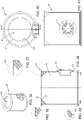
FIG. 35 is a perspective view of the housing that forms part of the milling chamber. -
FIG. 36 is a sectional view taken substantially along line 36-36 ofFIG. 40 . -
FIG. 37 is an enlarged partial and sectional view of the housing as shown inFIG. 36 . -
FIG. 38 is an enlarged and partial sectional view of the housing as shown inFIG. 36 . -
FIG. 39 is another enlarged and partial sectional view of the housing as shown inFIG. 36 . -
FIG. 40 is a top view of the housing as shown inFIGS. 35-36 and 40 . -
FIG. 41 is a front view of the housing as shown inFIGS. 35-36 . -
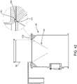
FIG. 42 is a sectional view of the housing, feed chute and screen. - The drawings are not necessarily to scale and may illustrate the disclosed embodiments diagrammatically and in partial views. In certain instances, the drawings omit details which are not necessary for an understanding of the disclosed methods and apparatuses or which render other details difficult to perceive. Further, this disclosure is not limited to the particular embodiments illustrated herein.
-
FIGS. 1-3 generally illustrate the configuration of a frusto-conical screen 50 for use in theconical mill 62 illustrated inFIGS. 23-28 . Thescreen 50 includes a taperedsidewall 51 that includes awider top 52 and anarrower bottom 53. The taperedsidewall 51 includes a plurality of openings oropenings 54 that are of a uniform size. Typically, the angle θ between diametrically opposed portions of the taperedsidewall 51 is about 60°, but the exact geometry of thescreen 50 may vary as will be apparent to those skilled in the art. The bottom 53 connects to another frusto-conical bottom section 55 for receiving thelower end 56 of theimpeller 57 illustrated in detail inFIGS. 17-20 . Thescreen 50 also includes anouter flange 58 for supporting thescreen 50 within thehousing 61 of the conical milling 62 as illustrated inFIGS. 24-25 . Thescreen 50 may also include atab 63 for ease of handling. -
FIG. 4 illustrates a partial top view of another disclosedscreen 50a that also includes a taperedsidewall 51a that includes a top 52a and a bottom 53a. Thescreen 50a also includes abottom section 55a for receiving thelower end 56 of theimpeller 57 and aflange 58a for supporting thescreen 50a at thegroove 101 at the top of thehousing 61 of the conical mill 62 (FIGS. 24-25 and36 ). The top view provided byFIG. 4 also reveals that thescreen 50a includes four distinct sections including anupper section 64 disposed inside the top 52a of the taperedsidewall 51a, an uppermiddle section 65, a lowermiddle section 66 and alower section 67. Thelower section 67 is disposed between the bottom 53a of the taperedsidewall 51a and the lowermiddle section 66, which is disposed between the uppermiddle section 65 andlower section 67, which is disposed between theupper section 64 and the lowermiddle section 66 as shown inFIG. 4 . The four sections 64-67 may have different hole patterns, different spacing distances betweenopenings 54 and different open area percentages as illustrated in greater detail inFIGS. 6-8 . - Each section includes a plurality of
openings 54 that may be of a uniform size. However, the spacing distances between theopenings 54 vary from theupper section 64 to thelower section 67. Theupper section 64 engages to the upper portions of themilling members impeller 57, which travel at a faster rotational velocity than lower portions of themilling members upper sections 64 of thescreen 50a are exposed to a greater amount of energy from theimpeller 57 while thelower section 67 of thescreen 50a is exposed to a lower amount of energy from the rotatingimpeller 57. Generally, the energy delivered by the rotatingimpeller 57 decreases along the taperedsidewall 51a from theupper section 64 to thebottom section 67. As a result,more openings 54 are required for theupper section 64 in order to reduce the residence time because the flowable material that is being milled in theupper section 64 will be reduced to within the target PSD before the flowable material being milled in the uppermiddle section 65, lowermiddle section 66 orlower section 67. In contrast, because thelower section 67 is engaged by the lower portions of themilling members impeller 57, which are traveling at the lowest rotational velocity, the flowable material being milled at thelower section 67 is exposed to less energy, and therefore requires a higher residence time to achieve the target PSD. Thus, thelower section 67 hasfewer openings 54, longer spacings betweenopenings 54 and a lower open area percentage. - Accordingly, in
FIG 5 , the spacing distance D1 of theupper section 64 is shorter than the spacing distance D2 of the uppermiddle section 65 illustrated inFIG. 6 , which is shorter than the spacing distance D3 of the lowermiddle section 66 as illustrated inFIG. 7 and which is shorter than the spacing distance D4 of thelower section 67 as illustrated inFIG. 8 . Thus, theupper section 64 has the highest open area percentage and the smallest spacing distance D1 betweenopenings 54 while thelower section 67 has the lowest open area percentage and the greatest spacing distance D4 betweenadjacent openings 54. - In the embodiment shown, the angle γ between the
openings 54 for the hole patterns illustrated inFIGS. 5-8 may be about 60° although the angle γ may vary as will be apparent to those skilled in the art. - The open area percentage for the four
distinct sections screen 50a may range from about 30% to about 50% for theupper section 64, from about 25% to about 45% for the uppermiddle section 65, from about 20% to about 40% for the lowermiddle section 66 and from about 15% to about 35% for thelower section 67. However, the open area percentages as well as the spacing distances D1-D4 may vary greatly, as will be dependent on the material being milled, the desired PSD, operating conditions and other factors as will be apparent to those skilled in the art. In one non-limiting example, the open area percentages for the sections 64-67 may be 40%, 35%, 30% and 25% respectively. - Turning to
FIGS. 9-10 , yet anotherscreen 50b is disclosed that includes the same structural features as thescreens flange 58b,bottom section 55b, and taperedsidewall 51b, which extends from a top 52b to a bottom 53b. Instead of a stepwise reduction an open area percentage from the top 52b to the bottom 53b, (or step-wise increase in the spacing distances from the top 52b to the bottom 53b) thescreen 50b features a gradual decrease in open area percentage (or increase in spacing distances) from the top 52b to the bottom 53b. The open area near the top 52b of the taperedsidewall 51b may range from about 30% to about 50%, depending upon the material being processed, the size of theopenings 54, the desired PSD, etc. Further, the open area percentage near the bottom 53b may range from about 15% to about 35%, depending upon a myriad of factors that will be apparent to those skilled in the art. In one non-limiting example, the open area percentage may be about 40% near the top 52b of the taperedsidewall 51b and about 25% at the bottom 53b of the taperedsidewall 51b. - Turning to
FIGS. 11-12 , asimilar screen 50c is illustrated that includes the same gradual reduction in open area percentage or increase in spacing distances from the top 52c to the bottom 53c of the taperedsidewall 51c. However, each opening 54 includes arasp element 73 for enhanced grinding/milling of the flowable material processed by theconical mill 62. Again, in an embodiment, the open area percentage decreases from the top 52c to the bottom 53c of the taperedsidewall 51c while the spacing distances increase from the top 52c to the bottom 53c. -
FIGS. 13-16 illustrate twoadditional screens openings circular openings 54 illustrated inFIGS. 1 ,5-8 and10 . However, the general concept remains the same; the open area percentage is highest towards the tops 52d, 52e of the taperedsidewalls 51d, 51e, and the open area percentage is the smallest at thebottoms sidewalls 51d, 51e, respectively. - Turning to
FIGS. 17-22 , the disclosedimpeller 57 includes arecess 75 for capturing an O-ring 76 that seals theinternal cavity 77 against theoutput shaft 78 of the gearbox 80 (seeFIGS. 29-32 ).Cross arms milling members central shaft 83 of theimpeller 57. Theshaft 83 of theimpeller 57 may couple to theoutput shaft 78 of thegearbox 80 using a key and slot connection or other suitable means of detachable attachment. Thelower end 56 of theimpeller 57 fits snuggly within thebottom sections lower end 56 of theimpeller 57 connects to themilling members lip 83a that rides on the junction of thebottoms sidewalls bottom sections screens FIGS. 3 ,18 and 22 . - In addition to the captured O-
ring 76 sealing the bottom 56 of theimpeller 57 against theoutput shaft 78, thegearbox 80 also includes aseal assembly 84 that further prevents any cross-contamination between thegearbox 80 and themilling chamber 85 provided by the housing 61 (seeFIGS. 35-41 ). Further, thegearbox 80 may include anoutput gear 87 that connects to theoutput shaft 78 and that meshes with aninput gear 88. Theinput gear 88 couples to aninput shaft 89, which couples to amotor 91, which can be seen inFIGS. 23 and 26 . In an embodiment, theinput gear 88 is fabricated from non-metallic composite materials. In a further refinement of this concept, non-metallic composite materials from which theinput gear 88 is fabricated may be of the type that does not require lubrication. Hence, thegearbox 80 may be a lubricantfree gearbox 80 with, in addition to theseal assembly 84 and captured O-ring 76, prevent contamination of lubricant or other materials from thegearbox 80 into the millingchamber 85. Theinput shaft 89 passes through agearbox housing 90 that sealably couples to a spindle housing 92 (FIG. 34 ) that accommodates aspindle 93 which, in turn, connects to themotor 91 illustrated inFIGS. 23 and 26 . The O-ring 115 seals thespindle housing 92 to thegearbox housing 90.FIG. 24 illustrates acollection receptacle 100 that, as will be apparent to those skilled in the art, may be a bin, a container or a conveying system, such as a pneumatic conveying system. -
FIGS. 23-28 illustrate one suitableconical mill 62. A supportingstand 94 may includewheels 95 and anupright support 96 for supporting acontrol panel 97. Thestand 94 may also include anadditional upright support 98 for supporting themotor 91, thespindle housing 92 and thehousing 61 of theconical mill 62. A feed chute 99 (FIGS. 23-26 and 28 ) is disposed above the uppercentral opening 102 of thehousing 61. Theperipheral groove 101 may accommodate an O-ring 110 (FIGS. 36-37 ) while theperipheral groove 151 in thelower flange 152 of thehousing 99 may accommodate an O-ring 160. The two O-rings feed chute 99 ensures that powders during milling are only present in the internal contact surface areas and cleaning solutions cannot escape or be trapped in crevices after a cleaning cycle. Thefeed chute 99 detachably couples to thehousing 61 via thehorizontal arm 103 andvertical cylinder 104 as best seen inFIGS. 23-24 . Turning toFIGS. 27 and36 , thehousing 61 also includes a bottomcentral opening 106 that is encircled by aflange 107 having a groove or slot 108 disposed therein for accommodating an O-ring 109 that enables the bottom flange 107 (FIGS. 27 and36 ) to be sealably secured to the receptacle 100 (FIG. 24 ). Thehousing 61 also includes a fitting 112 for receiving thespindle housing 92. The construction of thehousing 61,feed chute 99, screens 50, 50a-50e,impeller 57,gearbox 80 andspindle housing 92, along with the aforementioned O-rings conical mill 62 to be cleaned-in-place without presenting a safety hazard to the operator. - A
conical mill 62, animproved gearbox 80 for aconical mill 62, improved frusto-conical screens improved impeller 57 are disclosed herein and are suitable for use in many pharmaceutical, food, chemical or cosmetics applications. - The disclosed
conical mills 62, withimproved screens impeller 57 andgearbox 80, may provide any or all of the following benefits: from about 15% to greater than 50% improvement in narrowing PSDs; up to about 50% reduction in heat generation; from about 30% to greater than about 50% in increased capacity or throughput; reduced sound generation by up to 5 dBs; and the ability to clean theconical mill 62 without the need of opening themilling chamber 85 and without exposing the operator to the milled powder or dust. - While only certain embodiments have been set forth, alternatives and modifications will be apparent from the above description to those skilled in the art. These and other alternatives are considered equivalents and within the scope of this disclosure and the appended claims.
Claims (12)
- A screen (50) for a mill, the screen (50) comprising:
a tapered sidewall (51) having a wider top (52) and a narrower bottom (53), the sidewall (51) including a plurality of openings (54), each opening (54) separated from adjacent openings (54) by spacing distances, characterized in that the openings are of uniform size and in that the spacing distances at the top of the sidewall (51) are less than the spacing distances at the bottom of the sidewall (51) . - The screen (50) of claim 1 wherein an open area percentage provided by the openings (54) in the sidewall (51) is greater at the top of the sidewall (51) than at the bottom of the sidewall (51).
- The screen (50) of claim 1 wherein the sidewall (51) is frusto-conically shaped.
- The screen (50) of claim 1 wherein the openings (54) have a shape selected from the group consisting of round, square and rectangular.
- The screen (50) of claim 1 wherein the sidewall (51) at each opening (54) includes an inwardly extending rasp (73) or dimple.
- The screen (50) of claim 1 wherein the sidewall (51) includes a total surface area interrupted by the openings (54), the sidewall (51) also comprising an upper section (64), an upper middle section (65), a lower middle section (66) and a lower section (67), the openings (54) in the upper section (64) provide an open area percentage ranging from about 30% to about 50% of the total surface area of the sidewall (51) in the upper section (64), the openings (54) in the upper middle section (65) provide an open area percentage ranging from about 25% to about 45% of the total surface area of the sidewall (51) in the lower middle section (66), the openings (54) in the lower middle section provide an open area percentage ranging from about 20% to about 40% of the total surface area of the sidewall (51) in the lower middle section (66), and the openings (54) in the lower section (67) provide an open area percentage ranging from about 15% to about 35% of the total surface area of the sidewall (51) in the lower section (67).
- The screen (50) of claim 1 wherein the sidewall (51) includes a total surface area interrupted by the openings (54) that cumulatively provide an open area percentage, and wherein the open area percentage is about 40% at the top of the sidewall (51), the open area percentage is about 25% at the bottom of the sidewall (51) and the openings (54) disposed between the top and the bottom of the sidewall (51) provide an open area percentage ranging from less than 40% to greater than 25%.
- A method for size-reducing a flowable solid material, the method comprising:providing a mill comprising a housing (61) that accommodates a screen (50) between a top and a bottom of the housing (61), the screen (50) comprising a frusto-conically shaped sidewall (51) having a wider top (52) and a narrower bottom (53), the sidewall (51) including a plurality of openings (54), each opening separated from adjacent openings (54) by spacing distances, characterized in that the opening are of a uniform size and in that the spacing distances between the openings (54) at the top of the sidewall (51) being less than the spacing distances at the bottom of the sidewall (51), the sidewall (51) accommodating an impeller (57) mounted coaxially within the sidewall (51), the impeller (57) comprising at least one milling member that extends parallel to the sidewall (51) and from the bottom to the top of the sidewall (51),rotating the impeller (57),delivering the flowable solid material through the top of the housing (61) and through the top of the sidewall (51),pressing the flowable solid material through the openings (54) in the sidewall (51) to produce size-reduced material, andcollecting the size-reduced material.
- The method of claim 8 wherein the sidewall (51) at each opening includes an inwardly extending rasp (73).
- The method of claim 8 wherein the sidewall (51) includes a total surface area interrupted by the openings (54), the sidewall (51) also comprising an upper section (64), an upper middle section (65), a lower middle section (66) and a lower section (67), the openings (54) in the upper section (64) provide an open area percentage ranging from about 30% to about 50% of the total surface area of the sidewall (51) in the upper section (64), the openings (54) in the upper middle section (65) provide an open area percentage ranging from about 25% to about 45% of the total surface area of the sidewall (51) in the lower middle section (66), the openings (54) in the lower middle section (66) provide an open area percentage ranging from about 20% to about 40% of the total surface area of the sidewall (51) in the lower middle section (66), and the openings (54) in the lower section (67) provide an open area percentage ranging from about 15% to about 35% of the total surface area of the sidewall (51) in the lower section (67).
- The method of claim 8 wherein the sidewall (51) includes a total surface area interrupted by the openings (54) that cumulatively provide an open area percentage, and wherein the open area percentage is about 40% at the top of the sidewall (51), the open area percentage is about 25% at the bottom of the sidewall (51) and the openings (54) disposed between the top and the bottom of the sidewall (51) provide an open area percentage ranging from less than 40% to greater than 25%.
- The method of claim 8 wherein the impeller (57) further comprising a lower base disposed at the bottom of the sidewall of the screen (50) and connected to an output shaft that extends through the bottom of the sidewall, the base connected to at least one milling member that extends from the top to the bottom of the sidewall,the output shaft connected to an output gear, the output gear enmeshed with an input gear, the input gear connected to an input shaft, the input shaft connected to a motor,wherein the input gears are fabricated from non-metallic composite materials.
Applications Claiming Priority (2)
| Application Number | Priority Date | Filing Date | Title |
|---|---|---|---|
| US201562208281P | 2015-08-21 | 2015-08-21 | |
| PCT/IB2016/001130 WO2017033050A1 (en) | 2015-08-21 | 2016-07-12 | High efficiency conical mills |
Publications (3)
| Publication Number | Publication Date |
|---|---|
| EP3337617A1 EP3337617A1 (en) | 2018-06-27 |
| EP3337617A4 EP3337617A4 (en) | 2019-04-24 |
| EP3337617B1 true EP3337617B1 (en) | 2022-11-09 |
Family
ID=58099831
Family Applications (1)
| Application Number | Title | Priority Date | Filing Date |
|---|---|---|---|
| EP16838617.5A Active EP3337617B1 (en) | 2015-08-21 | 2016-07-12 | High efficiency conical mills |
Country Status (6)
| Country | Link |
|---|---|
| US (1) | US10987676B2 (en) |
| EP (1) | EP3337617B1 (en) |
| JP (1) | JP6750015B2 (en) |
| CN (1) | CN108025313B (en) |
| CA (1) | CA2996074C (en) |
| WO (1) | WO2017033050A1 (en) |
Families Citing this family (1)
| Publication number | Priority date | Publication date | Assignee | Title |
|---|---|---|---|---|
| US20220110485A1 (en) * | 2020-10-09 | 2022-04-14 | Wilson Roberto Dos Santos | Storage and granulation system |
Family Cites Families (20)
| Publication number | Priority date | Publication date | Assignee | Title |
|---|---|---|---|---|
| GB609757A (en) * | 1946-03-20 | 1948-10-06 | David Rozentraub | A vegetable masher |
| DE3006364B1 (en) | 1980-02-20 | 1980-11-13 | Steinhaus Gmbh | Perforated plate sieve bottom with self-cleaning effect |
| JPS604634Y2 (en) * | 1981-12-08 | 1985-02-09 | 太昭農工機株式会社 | Sorting device for dried shiitake mushrooms, etc. |
| US4759507A (en) | 1985-04-04 | 1988-07-26 | Quadro Engineering Incorporated | Size reduction machine having an external gap adjustment |
| US5282579A (en) * | 1993-01-25 | 1994-02-01 | Poser Kimberly J | Apparatus for adjusting the gap of a size reduction machine |
| US5330113A (en) * | 1993-03-29 | 1994-07-19 | Quadro Engineering Inc. | Underdriven size reduction machine |
| US5615969A (en) * | 1993-11-08 | 1997-04-01 | Kemutec Group, Ltd. | Rotary drive coupling |
| US5405094A (en) * | 1994-01-31 | 1995-04-11 | Poser; Kimberly | Multi-staged size reduction machine |
| JP2904399B2 (en) | 1994-09-27 | 1999-06-14 | 株式会社栗本鐵工所 | Rotating structure of vertical planetary ball mill |
| JP3151703B2 (en) * | 1995-08-11 | 2001-04-03 | 深江パウテック株式会社 | Granular crushing and sizing device and annular space type screen |
| US5607062A (en) * | 1995-08-18 | 1997-03-04 | Quadro Engineering Inc. | Screen module for preparing cosmetics nested screens of different mesh sizes |
| US6367723B1 (en) * | 2000-02-07 | 2002-04-09 | The Fitzpatrick Company | Size reduction machine having an adjustable impeller and screen holder |
| JP2002192017A (en) * | 2000-12-26 | 2002-07-10 | Dainippon Ink & Chem Inc | Separation device |
| KR100740687B1 (en) * | 2001-02-28 | 2007-07-18 | 박종현 | Milling machine |
| GB2395675A (en) | 2002-11-30 | 2004-06-02 | Hanningfield Process Systems L | Size reduction mill having co-axially mounted screen and impeller, and a perip heral drive means |
| FR2924435B1 (en) * | 2007-11-30 | 2010-12-31 | Inst Francais Du Petrole | METHOD AND DEVICE FOR TORREFACTING AND MILLING FLUIDIZED BED OF A BIOMASS LOAD FOR GASIFICATION OR SUBSEQUENT COMBUSTION |
| KR100934435B1 (en) | 2008-02-22 | 2009-12-29 | 주식회사 정현프랜트 | Chemical Grinder |
| CN202981523U (en) | 2012-12-19 | 2013-06-12 | 杨文焌 | Filter screen structure of a juice extractor |
| CN204017916U (en) * | 2013-10-31 | 2014-12-17 | 太仓北新建材有限公司 | A kind of hammer mill sieve-plate structure |
| CN204220209U (en) * | 2014-06-23 | 2015-03-25 | 新疆金宇鑫新材料有限公司 | A kind of inner from return ash circulation type sand machine |
-
2016
- 2016-07-12 CN CN201680047759.2A patent/CN108025313B/en active Active
- 2016-07-12 CA CA2996074A patent/CA2996074C/en active Active
- 2016-07-12 US US15/753,818 patent/US10987676B2/en active Active
- 2016-07-12 WO PCT/IB2016/001130 patent/WO2017033050A1/en not_active Ceased
- 2016-07-12 JP JP2018528103A patent/JP6750015B2/en active Active
- 2016-07-12 EP EP16838617.5A patent/EP3337617B1/en active Active
Also Published As
| Publication number | Publication date |
|---|---|
| EP3337617A1 (en) | 2018-06-27 |
| HK1249075A1 (en) | 2018-10-26 |
| JP6750015B2 (en) | 2020-09-02 |
| EP3337617A4 (en) | 2019-04-24 |
| WO2017033050A1 (en) | 2017-03-02 |
| US20190009278A1 (en) | 2019-01-10 |
| JP2018523577A (en) | 2018-08-23 |
| CN108025313B (en) | 2020-12-22 |
| CA2996074C (en) | 2021-12-14 |
| CA2996074A1 (en) | 2017-03-02 |
| US10987676B2 (en) | 2021-04-27 |
| CN108025313A (en) | 2018-05-11 |
Similar Documents
| Publication | Publication Date | Title |
|---|---|---|
| JP2693375B2 (en) | Subdivision device | |
| CN105682805B (en) | Suitable for the pre- grinding mechanism of ball mill or agitating ball mill and the ball mill with pre- grinding mechanism | |
| EP2293877B1 (en) | Conical reducing apparatus | |
| US6394374B1 (en) | Disintegrating and grain-regulating device for granules | |
| DE102005046207B4 (en) | Device for crushing debris | |
| EP0719585A1 (en) | Agitator mill with separator for retaining milling beads | |
| JP2003159521A (en) | Apparatus for treating material | |
| CA2996074C (en) | High efficiency conical mills | |
| CN116237126A (en) | Vertical sand mill | |
| EP3450023B1 (en) | Improvements in or relating to cone mills | |
| CN205341023U (en) | Grinding and granulating machine | |
| HK1249075B (en) | High efficiency conical mills | |
| US8820667B2 (en) | Sieve mill with improved sieve retaining properties | |
| KR20080014115A (en) | Scrap iron rotary separator | |
| KR101565243B1 (en) | Pulverizer for agricultural product | |
| EP4529819B1 (en) | Grinding device | |
| WO2021080547A1 (en) | A dosing means | |
| JP3962262B2 (en) | Flake production equipment | |
| CN106076198B (en) | A kind of pelletizer | |
| CN111468267B (en) | Granulated sugar crushing, dust separation and filtering system | |
| CN214688117U (en) | Dustproof powder feeding system | |
| CN217249342U (en) | Safe and environment-friendly crushing and grinding device | |
| CN207478965U (en) | A kind of chilli powder mixing equipment pre-sifted separating device | |
| KR102106734B1 (en) | Self-removing fume detector attached to a magnet | |
| GB2450888A (en) | A method of treating filter elements |
Legal Events
| Date | Code | Title | Description |
|---|---|---|---|
| STAA | Information on the status of an ep patent application or granted ep patent |
Free format text: STATUS: THE INTERNATIONAL PUBLICATION HAS BEEN MADE |
|
| PUAI | Public reference made under article 153(3) epc to a published international application that has entered the european phase |
Free format text: ORIGINAL CODE: 0009012 |
|
| STAA | Information on the status of an ep patent application or granted ep patent |
Free format text: STATUS: REQUEST FOR EXAMINATION WAS MADE |
|
| 17P | Request for examination filed |
Effective date: 20180316 |
|
| AK | Designated contracting states |
Kind code of ref document: A1 Designated state(s): AL AT BE BG CH CY CZ DE DK EE ES FI FR GB GR HR HU IE IS IT LI LT LU LV MC MK MT NL NO PL PT RO RS SE SI SK SM TR |
|
| AX | Request for extension of the european patent |
Extension state: BA ME |
|
| RIN1 | Information on inventor provided before grant (corrected) |
Inventor name: WATSON, BARRY Inventor name: WATSON, SEAN Inventor name: SANGUESA, WILF Inventor name: VERBERNE, JEFF |
|
| RIN1 | Information on inventor provided before grant (corrected) |
Inventor name: VERBERNE, JEFF Inventor name: WATSON, SEAN Inventor name: SANGUESA, WILF Inventor name: WATSON, BARRY |
|
| DAV | Request for validation of the european patent (deleted) | ||
| DAX | Request for extension of the european patent (deleted) | ||
| A4 | Supplementary search report drawn up and despatched |
Effective date: 20190326 |
|
| RIC1 | Information provided on ipc code assigned before grant |
Ipc: B02C 23/16 20060101ALI20190320BHEP Ipc: B02C 13/284 20060101AFI20190320BHEP Ipc: B02C 18/06 20060101ALI20190320BHEP |
|
| GRAP | Despatch of communication of intention to grant a patent |
Free format text: ORIGINAL CODE: EPIDOSNIGR1 |
|
| STAA | Information on the status of an ep patent application or granted ep patent |
Free format text: STATUS: GRANT OF PATENT IS INTENDED |
|
| INTG | Intention to grant announced |
Effective date: 20220718 |
|
| GRAS | Grant fee paid |
Free format text: ORIGINAL CODE: EPIDOSNIGR3 |
|
| GRAA | (expected) grant |
Free format text: ORIGINAL CODE: 0009210 |
|
| STAA | Information on the status of an ep patent application or granted ep patent |
Free format text: STATUS: THE PATENT HAS BEEN GRANTED |
|
| AK | Designated contracting states |
Kind code of ref document: B1 Designated state(s): AL AT BE BG CH CY CZ DE DK EE ES FI FR GB GR HR HU IE IS IT LI LT LU LV MC MK MT NL NO PL PT RO RS SE SI SK SM TR |
|
| REG | Reference to a national code |
Ref country code: GB Ref legal event code: FG4D |
|
| REG | Reference to a national code |
Ref country code: CH Ref legal event code: EP Ref country code: AT Ref legal event code: REF Ref document number: 1530007 Country of ref document: AT Kind code of ref document: T Effective date: 20221115 |
|
| REG | Reference to a national code |
Ref country code: DE Ref legal event code: R096 Ref document number: 602016076263 Country of ref document: DE |
|
| REG | Reference to a national code |
Ref country code: IE Ref legal event code: FG4D |
|
| REG | Reference to a national code |
Ref country code: LT Ref legal event code: MG9D |
|
| REG | Reference to a national code |
Ref country code: NL Ref legal event code: MP Effective date: 20221109 |
|
| REG | Reference to a national code |
Ref country code: AT Ref legal event code: MK05 Ref document number: 1530007 Country of ref document: AT Kind code of ref document: T Effective date: 20221109 |
|
| PG25 | Lapsed in a contracting state [announced via postgrant information from national office to epo] |
Ref country code: SE Free format text: LAPSE BECAUSE OF FAILURE TO SUBMIT A TRANSLATION OF THE DESCRIPTION OR TO PAY THE FEE WITHIN THE PRESCRIBED TIME-LIMIT Effective date: 20221109 Ref country code: PT Free format text: LAPSE BECAUSE OF FAILURE TO SUBMIT A TRANSLATION OF THE DESCRIPTION OR TO PAY THE FEE WITHIN THE PRESCRIBED TIME-LIMIT Effective date: 20230309 Ref country code: NO Free format text: LAPSE BECAUSE OF FAILURE TO SUBMIT A TRANSLATION OF THE DESCRIPTION OR TO PAY THE FEE WITHIN THE PRESCRIBED TIME-LIMIT Effective date: 20230209 Ref country code: LT Free format text: LAPSE BECAUSE OF FAILURE TO SUBMIT A TRANSLATION OF THE DESCRIPTION OR TO PAY THE FEE WITHIN THE PRESCRIBED TIME-LIMIT Effective date: 20221109 Ref country code: FI Free format text: LAPSE BECAUSE OF FAILURE TO SUBMIT A TRANSLATION OF THE DESCRIPTION OR TO PAY THE FEE WITHIN THE PRESCRIBED TIME-LIMIT Effective date: 20221109 Ref country code: ES Free format text: LAPSE BECAUSE OF FAILURE TO SUBMIT A TRANSLATION OF THE DESCRIPTION OR TO PAY THE FEE WITHIN THE PRESCRIBED TIME-LIMIT Effective date: 20221109 Ref country code: AT Free format text: LAPSE BECAUSE OF FAILURE TO SUBMIT A TRANSLATION OF THE DESCRIPTION OR TO PAY THE FEE WITHIN THE PRESCRIBED TIME-LIMIT Effective date: 20221109 |
|
| PG25 | Lapsed in a contracting state [announced via postgrant information from national office to epo] |
Ref country code: RS Free format text: LAPSE BECAUSE OF FAILURE TO SUBMIT A TRANSLATION OF THE DESCRIPTION OR TO PAY THE FEE WITHIN THE PRESCRIBED TIME-LIMIT Effective date: 20221109 Ref country code: PL Free format text: LAPSE BECAUSE OF FAILURE TO SUBMIT A TRANSLATION OF THE DESCRIPTION OR TO PAY THE FEE WITHIN THE PRESCRIBED TIME-LIMIT Effective date: 20221109 Ref country code: LV Free format text: LAPSE BECAUSE OF FAILURE TO SUBMIT A TRANSLATION OF THE DESCRIPTION OR TO PAY THE FEE WITHIN THE PRESCRIBED TIME-LIMIT Effective date: 20221109 Ref country code: IS Free format text: LAPSE BECAUSE OF FAILURE TO SUBMIT A TRANSLATION OF THE DESCRIPTION OR TO PAY THE FEE WITHIN THE PRESCRIBED TIME-LIMIT Effective date: 20230309 Ref country code: HR Free format text: LAPSE BECAUSE OF FAILURE TO SUBMIT A TRANSLATION OF THE DESCRIPTION OR TO PAY THE FEE WITHIN THE PRESCRIBED TIME-LIMIT Effective date: 20221109 Ref country code: GR Free format text: LAPSE BECAUSE OF FAILURE TO SUBMIT A TRANSLATION OF THE DESCRIPTION OR TO PAY THE FEE WITHIN THE PRESCRIBED TIME-LIMIT Effective date: 20230210 |
|
| PG25 | Lapsed in a contracting state [announced via postgrant information from national office to epo] |
Ref country code: NL Free format text: LAPSE BECAUSE OF FAILURE TO SUBMIT A TRANSLATION OF THE DESCRIPTION OR TO PAY THE FEE WITHIN THE PRESCRIBED TIME-LIMIT Effective date: 20221109 |
|
| PG25 | Lapsed in a contracting state [announced via postgrant information from national office to epo] |
Ref country code: SM Free format text: LAPSE BECAUSE OF FAILURE TO SUBMIT A TRANSLATION OF THE DESCRIPTION OR TO PAY THE FEE WITHIN THE PRESCRIBED TIME-LIMIT Effective date: 20221109 Ref country code: RO Free format text: LAPSE BECAUSE OF FAILURE TO SUBMIT A TRANSLATION OF THE DESCRIPTION OR TO PAY THE FEE WITHIN THE PRESCRIBED TIME-LIMIT Effective date: 20221109 Ref country code: EE Free format text: LAPSE BECAUSE OF FAILURE TO SUBMIT A TRANSLATION OF THE DESCRIPTION OR TO PAY THE FEE WITHIN THE PRESCRIBED TIME-LIMIT Effective date: 20221109 Ref country code: DK Free format text: LAPSE BECAUSE OF FAILURE TO SUBMIT A TRANSLATION OF THE DESCRIPTION OR TO PAY THE FEE WITHIN THE PRESCRIBED TIME-LIMIT Effective date: 20221109 Ref country code: CZ Free format text: LAPSE BECAUSE OF FAILURE TO SUBMIT A TRANSLATION OF THE DESCRIPTION OR TO PAY THE FEE WITHIN THE PRESCRIBED TIME-LIMIT Effective date: 20221109 |
|
| REG | Reference to a national code |
Ref country code: DE Ref legal event code: R097 Ref document number: 602016076263 Country of ref document: DE |
|
| PG25 | Lapsed in a contracting state [announced via postgrant information from national office to epo] |
Ref country code: SK Free format text: LAPSE BECAUSE OF FAILURE TO SUBMIT A TRANSLATION OF THE DESCRIPTION OR TO PAY THE FEE WITHIN THE PRESCRIBED TIME-LIMIT Effective date: 20221109 Ref country code: AL Free format text: LAPSE BECAUSE OF FAILURE TO SUBMIT A TRANSLATION OF THE DESCRIPTION OR TO PAY THE FEE WITHIN THE PRESCRIBED TIME-LIMIT Effective date: 20221109 |
|
| PLBE | No opposition filed within time limit |
Free format text: ORIGINAL CODE: 0009261 |
|
| STAA | Information on the status of an ep patent application or granted ep patent |
Free format text: STATUS: NO OPPOSITION FILED WITHIN TIME LIMIT |
|
| 26N | No opposition filed |
Effective date: 20230810 |
|
| PG25 | Lapsed in a contracting state [announced via postgrant information from national office to epo] |
Ref country code: SI Free format text: LAPSE BECAUSE OF FAILURE TO SUBMIT A TRANSLATION OF THE DESCRIPTION OR TO PAY THE FEE WITHIN THE PRESCRIBED TIME-LIMIT Effective date: 20221109 |
|
| PG25 | Lapsed in a contracting state [announced via postgrant information from national office to epo] |
Ref country code: MC Free format text: LAPSE BECAUSE OF FAILURE TO SUBMIT A TRANSLATION OF THE DESCRIPTION OR TO PAY THE FEE WITHIN THE PRESCRIBED TIME-LIMIT Effective date: 20221109 |
|
| PG25 | Lapsed in a contracting state [announced via postgrant information from national office to epo] |
Ref country code: MC Free format text: LAPSE BECAUSE OF FAILURE TO SUBMIT A TRANSLATION OF THE DESCRIPTION OR TO PAY THE FEE WITHIN THE PRESCRIBED TIME-LIMIT Effective date: 20221109 |
|
| REG | Reference to a national code |
Ref country code: BE Ref legal event code: MM Effective date: 20230731 |
|
| PG25 | Lapsed in a contracting state [announced via postgrant information from national office to epo] |
Ref country code: LU Free format text: LAPSE BECAUSE OF NON-PAYMENT OF DUE FEES Effective date: 20230712 |
|
| PG25 | Lapsed in a contracting state [announced via postgrant information from national office to epo] |
Ref country code: LU Free format text: LAPSE BECAUSE OF NON-PAYMENT OF DUE FEES Effective date: 20230712 |
|
| REG | Reference to a national code |
Ref country code: IE Ref legal event code: MM4A |
|
| PG25 | Lapsed in a contracting state [announced via postgrant information from national office to epo] |
Ref country code: BE Free format text: LAPSE BECAUSE OF NON-PAYMENT OF DUE FEES Effective date: 20230731 |
|
| PG25 | Lapsed in a contracting state [announced via postgrant information from national office to epo] |
Ref country code: IE Free format text: LAPSE BECAUSE OF NON-PAYMENT OF DUE FEES Effective date: 20230712 |
|
| PG25 | Lapsed in a contracting state [announced via postgrant information from national office to epo] |
Ref country code: IE Free format text: LAPSE BECAUSE OF NON-PAYMENT OF DUE FEES Effective date: 20230712 |
|
| PG25 | Lapsed in a contracting state [announced via postgrant information from national office to epo] |
Ref country code: BG Free format text: LAPSE BECAUSE OF FAILURE TO SUBMIT A TRANSLATION OF THE DESCRIPTION OR TO PAY THE FEE WITHIN THE PRESCRIBED TIME-LIMIT Effective date: 20221109 |
|
| PG25 | Lapsed in a contracting state [announced via postgrant information from national office to epo] |
Ref country code: BG Free format text: LAPSE BECAUSE OF FAILURE TO SUBMIT A TRANSLATION OF THE DESCRIPTION OR TO PAY THE FEE WITHIN THE PRESCRIBED TIME-LIMIT Effective date: 20221109 |
|
| PG25 | Lapsed in a contracting state [announced via postgrant information from national office to epo] |
Ref country code: CY Free format text: LAPSE BECAUSE OF FAILURE TO SUBMIT A TRANSLATION OF THE DESCRIPTION OR TO PAY THE FEE WITHIN THE PRESCRIBED TIME-LIMIT; INVALID AB INITIO Effective date: 20160712 |
|
| PG25 | Lapsed in a contracting state [announced via postgrant information from national office to epo] |
Ref country code: HU Free format text: LAPSE BECAUSE OF FAILURE TO SUBMIT A TRANSLATION OF THE DESCRIPTION OR TO PAY THE FEE WITHIN THE PRESCRIBED TIME-LIMIT; INVALID AB INITIO Effective date: 20160712 |
|
| PGFP | Annual fee paid to national office [announced via postgrant information from national office to epo] |
Ref country code: DE Payment date: 20250722 Year of fee payment: 10 |
|
| PGFP | Annual fee paid to national office [announced via postgrant information from national office to epo] |
Ref country code: IT Payment date: 20250724 Year of fee payment: 10 |
|
| PGFP | Annual fee paid to national office [announced via postgrant information from national office to epo] |
Ref country code: GB Payment date: 20250722 Year of fee payment: 10 |
|
| PGFP | Annual fee paid to national office [announced via postgrant information from national office to epo] |
Ref country code: FR Payment date: 20250725 Year of fee payment: 10 |
|
| PGFP | Annual fee paid to national office [announced via postgrant information from national office to epo] |
Ref country code: CH Payment date: 20250801 Year of fee payment: 10 |
|
| PG25 | Lapsed in a contracting state [announced via postgrant information from national office to epo] |
Ref country code: TR Free format text: LAPSE BECAUSE OF FAILURE TO SUBMIT A TRANSLATION OF THE DESCRIPTION OR TO PAY THE FEE WITHIN THE PRESCRIBED TIME-LIMIT Effective date: 20221109 |