EP3337383B1 - Eyelid shape estimation - Google Patents
Eyelid shape estimation Download PDFInfo
- Publication number
- EP3337383B1 EP3337383B1 EP16839826.1A EP16839826A EP3337383B1 EP 3337383 B1 EP3337383 B1 EP 3337383B1 EP 16839826 A EP16839826 A EP 16839826A EP 3337383 B1 EP3337383 B1 EP 3337383B1
- Authority
- EP
- European Patent Office
- Prior art keywords
- eye
- eyelid
- candidate points
- box
- fit curve
- Prior art date
- Legal status (The legal status is an assumption and is not a legal conclusion. Google has not performed a legal analysis and makes no representation as to the accuracy of the status listed.)
- Active
Links
Images


Classifications
-
- G—PHYSICS
- G06—COMPUTING OR CALCULATING; COUNTING
- G06V—IMAGE OR VIDEO RECOGNITION OR UNDERSTANDING
- G06V40/00—Recognition of biometric, human-related or animal-related patterns in image or video data
- G06V40/10—Human or animal bodies, e.g. vehicle occupants or pedestrians; Body parts, e.g. hands
- G06V40/16—Human faces, e.g. facial parts, sketches or expressions
- G06V40/168—Feature extraction; Face representation
- G06V40/171—Local features and components; Facial parts ; Occluding parts, e.g. glasses; Geometrical relationships
-
- G—PHYSICS
- G06—COMPUTING OR CALCULATING; COUNTING
- G06V—IMAGE OR VIDEO RECOGNITION OR UNDERSTANDING
- G06V40/00—Recognition of biometric, human-related or animal-related patterns in image or video data
- G06V40/10—Human or animal bodies, e.g. vehicle occupants or pedestrians; Body parts, e.g. hands
- G06V40/18—Eye characteristics, e.g. of the iris
- G06V40/193—Preprocessing; Feature extraction
Definitions
- the present disclosure relates generally to systems and methods for processing eye imagery.
- Biometric information can provide authentication or identification of an individual.
- the invention is directed to a method according to claim 1 and a system according to claim 4. Further developments are according to dependent claims 2, 3 and 5-7.
- Extracting biometric information from an eye generally includes a procedure for the segmentation of the iris within an eye image.
- Iris segmentation can involve operations including locating the iris boundaries, including finding the pupillary and limbic boundaries of the iris; localizing upper or lower eyelids if they occlude the iris; detecting and excluding occlusions of eyelashes, shadows, or reflections, and so forth.
- the eye image can be included in an image of the face or may be an image of the periocular region of the eye.
- both the pupillary boundary the interior boundary of the iris
- the limbic boundary the exterior boundary of the iris
- the portion of the iris that is occluded by the eyelids (upper or lower) can be estimated. This estimation is performed because, during normal human activity, the entire iris of a person is rarely visible. In other words, the entire iris is not generally free from occlusions of the eyelids and eyelashes.
- Embodiments of eyelid shape estimation described herein advantageously can be used for estimating the portion of the iris occluded by eyelids.
- the eyelid shape estimation can be used, for example, to identify biometric traits (e.g., eyelid shape), or reconstruct poses or orientations of the body or parts of a body (e.g., an eye) from an analysis of an eye image.
- the eyelid shape estimation can be used to detect a blinking eye in an eye image. Since a blinking eye may occlude portions of the iris, detection of an eye blink, and removal of the corresponding eye image, may improve the quality of iris segmentation and iris authentication techniques. Also, by identifying an eyelid shape of an eye in an eye image, eyelid portions of the eye in the eye image can be removed to reduce the amount of calculations for iris segmentation techniques so that substantially only the iris portion of the eye is used for biometric authentication.
- an eye-box over an eye image including an eye.
- the eye-box can be placed over the portion of the eye image.
- an eye image can be obtained from a still image or a video.
- An eye-box can be generated over the eye image with a plurality of radial lines extending to the edge of the eye-box, for example, from the center of eye-box.
- the upper and lower edges of the eye-box can roughly trace the boundary between the eyelid (upper or lower respectively) with the iris.
- the eye-box can be used to assist in eyelid shape estimation.
- video is used in its ordinary sense and includes, but is not limited to, a recording of a sequence of visual images.
- Each image in a video is sometimes referred to as an image frame or simply a frame.
- a video can include a plurality of sequential frames, either with or without an audio channel.
- a video can include a plurality of frames, which are ordered in time. Accordingly, an image in a video can be referred to as an eye image frame or eye image.
- candidate points can be determined with an edge detector.
- An iterative process can be used to randomly sample a subset of those candidate points to fit a curve (e.g., a parabolic line) to an estimated eyelid shape.
- scores for the curves is determined using a measure of goodness of fit.
- a preferred curve can be determined by assessing which of the curves has the highest score and/or which of the curves exceeds a score threshold.
- Candidate points that are sufficiently far from the preferred curve (e.g., beyond a threshold distance) may be considered "outlier" points and excluded from subsequent fitting or analysis.
- the remaining candidate points can be considered to be "inlier” points.
- the preferred curve can be refitted using some or all points that are considered to be “inlier” points, which can provide an improved or optimal curve that fits the eyelid (e.g., by excluding outlier points that likely are not representative of the position of the eyelid).
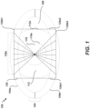
- FIG. 1 illustrates an image of an eye 100 with eyelids 104, sclera 108 (the "white" of the eye), iris 112, and pupil 116.
- Curve 116a shows the pupillary boundary between the pupil 116 and the iris 112
- curve 112a shows the limbic boundary between the iris 112 and the sclera 108.
- the eyelids 104 include an upper eyelid 104a and a lower eyelid 104b.
- FIG. 1 also schematically illustrates an example of an eye-box 120 over the eye image of the eye 100 as well as a plurality of radial lines 128a.
- the eye-box 120 can be overlaid on the eye 100 in the eye image using processes such as using an image processing algorithm that maps the eye-box 120 to particular portions of the eye image. Overlaying an eye-box 120 on the image of the eye 100 can also be referred to as generating an eye-box 120 or constructing an eye-box 120.
- the eye-box 120 can be overlaid on a video using processes such as using a video processing algorithm that can track an eye-box 120 through a plurality of sequential frames, and overlay the eye with an eye-box 120 as the video progresses through time.
- the eye-box 120 can be overlaid on the eye 100 in the eye image after a limbic boundary 112a or an approximation of the limbic boundary 112a is determined.
- the eye-box 120 can be placed such that the limbic boundary is inside the boundary of the eye-box 120 overlaid on the eye image.
- the region of the iris 112 not covered by the eyelids 104 can be inside the boundary of the eye-box 120.
- the eye-box 120 can be placed such that the approximation of the limbic boundary is inside the boundary of the eye-box 120 overlaid on the eye image.
- the region of the iris 112 not covered by the eyelids 104 or a majority of the region of the iris 112 not covered by the eyelids 104 can be inside the boundary of the eye-box 120.
- the eye-box 120 can be rectangular in shape. In some implementations, the eye-box 120 can be sized so as to be a minimum size bounding box that includes the entire iris 112.
- the eye-box 120 is shaped so that vertical edges 124a1, 124a2 of the eye-box 120 are tangent to the outermost portions of the limbic boundary 112a of the iris 112.
- the eye-box 120 can be shaped so that the horizontal edge 124b1 (or 124b2) of the eye-box 120 extends substantially outside the boundary of the upper eyelid 104a (or the lower eyelid 104b) and iris 112. That is, the horizontal edge 124b1 (or 124b2) can intersect that boundary. But, as depicted in FIG.
- the horizontal edge 124b1 (or 124b2) needs not intersect the boundary at any point.
- the eye-box 120 can be shaped so that the horizontal edge 124b1 (or 124b2) extends beyond the boundary of the upper eyelid 104a (or the lower eyelid 104b) and the iris 112, at any intersecting point along that boundary. Accordingly, the shape of the eye-box 120 can change based on the edge of upper eyelid 104a or lower eyelid 104b that is occluding the iris 112.
- the eye-box 120 is cropped to be square.
- the eye-box may be shaped as a parallelogram. For example, a parallelogram can be determined from a perspective transformation applied to a square eye-box located in the plane of the iris.
- a plurality of radial lines 128a are generated from the pupil 116 (e.g., emanating from the center or around the center of the pupil 116) towards the top edge 124b1 of the eye-box 120 (for the upper eyelid 104a) or towards the bottom edge 124b2 of the eye-box 120 (for the lower eyelid 104b).
- Generating the plurality of radial lines 128a can also be referred to as constructing the plurality of radial lines 128a.
- a radial line 128a can be a line from the first pixel of the horizontal edge 124b1 closer to the upper eyelid 104a to the last pixel of the horizontal edge 124b2 closer to the lower eyelid 104b.
- a radial line 128a can be a line from the second pixel of the horizontal edge 124b1 closer to the upper eyelid 104a to the n -1 pixel of the horizontal edge 124b2 closer to the lower eyelid 104b, where n denotes the width of the eye-box 120.
- the number of radial lines 128a may be as many as the width of the image, measured in pixels, or it may be a subsampling of this width.
- a sampling process can be used to select certain radial lines to be used for eyelid shape estimation so that sufficient lines cross the eyelids to provide a good fit to the eyelid shape.
- the sampling process can sample according to a width pixel (e.g., 2, 5, 10, or more pixels) threshold that allows the eyelid shape to be estimated within a certain error threshold.
- a width pixel e.g., 2, 5, 10, or more pixels
- any appropriate number of radial lines 128a can be utilized within the eye-box 120.
- the number of radial lines 128a can be the number of pixels in width across the eye image.
- the number of radial lines 128a can be optimized to be the minimal number of lines that allow the eyelid shape to be estimated within a certain error threshold.
- 3, 5, 7, 10, 15, 20, 30, or more lines can be used.
- the number of lines can be representative of the typical angular range subtended by an eyelid in an eye image, which is typically less than 180 degrees (for each eyelid).
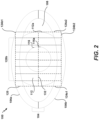
- FIG. 2 schematically illustrates an example, not belonging to the invention, of an eye 100 and an eye-box 120 including a plurality of vertical lines 128b that intersect the eyelids 104.
- the plurality of vertical lines 128b can be used in place of or in addition to the plurality of radial lines 128a.
- the plurality of vertical lines 128a can be generated that are parallel to the vertical edges 124a1, 124a2 of the eye-box 120, emanating from a horizontal bisector line 132 of the pupil 116.
- the number of lines (for each eyelid 104) can be as many as the width (in terms of pixels or any other suitable measurement such as millimeter) of the image.
- the number of lines can also be a subsampling of the width of the eye image.
- a line with any shape that extends generally outward from the pupil 116 (or the horizontal bisector line 132) to meet or cross the eyelids 104 can be used.
- a line needs not be a straight line (radial or vertical) but can be curved or have any suitable shape.
- the eye-box 120 illustrated in FIG. 1 is rectangular in shape.
- the eye-box 120 can have shapes such as polygonal or geometrical shapes (e.g., circles, ovals, etc.) generated around the boundary of the iris 112.
- a hexagonal shape can be used for the eye-box 120.
- eye-box can refer to any polygonal shape or geometric shape generated around the eye 100 so as to include the iris 112.
- a plurality of lines that can be considered analogous to the plurality of radial lines 128a in FIG. 1 or the plurality of vertical lines 128b in FIG. 2 can be generated from the center or around the center of that polygonal shape to the edges of that polygonal shape.
- FIG. 3 schematically illustrates an example of eyelid shape estimation.
- eyelid shape estimation can also be referred to as eyelid shape determination.
- An example of eyelid shape determination will be discussed using the rectangular eye-box 120 and the plurality of radial lines 128a shown in FIG. 1 .
- the technique can be performed using a non-rectangular eye-box 120 such as a hexagonal eye-box 120.
- the technique can be performed using the plurality of vertical lines 128b shown in FIG. 2 or any shape of line.
- a candidate point 136a (for estimating the shape of the upper eyelid 104a) or a candidate point 136b (for estimating the shape of the lower eyelid 104b) can be computed for each radial line 128a.
- a candidate point 136a or 136b can be a candidate for being a point along a portion of the edge of the eyelids 104a or 104b.
- the candidate point 136a can be a candidate for estimating the shape of the upper eyelid 104a.
- the candidate point 136b can be a candidate for estimating the shape of the lower eyelid 104b.
- the point at which the maximum derivative is identified is along the direction of the radial line 128a.
- the maximum derivative is used to find edges in the eye image, where there is a large change in image intensity, color, luminance, etc.
- a given line may have several points where the derivatives are large, e.g., the pupil boundary 116a, the limbic boundary 112a, and the eyelid 104a or 104b.
- a candidate point 136a or 136b is selected as the point with a large derivative value (e.g., local maximum) and which has the largest distance from the center of the pupil 116 (or from the bisector line 132).
- the derivative can be determined using numerical methods.
- a Sobel derivative operator (or a linear combination thereof) is used to determine the derivative along the radial line 128a.
- a Gabor filter convolution can be used to determine a derivative for the line 128a.
- An edge detection algorithm e.g., a Canny edge detector
- determining the maximum derivative can be viewed as applying an image processing filter to the plurality of radial lines 128a.
- the filter can be represented as a discrete differentiation operator. This filter can be convolved with the eye image to generate an image processing result comprising the maximum derivatives (or approximations thereof).
- the filter can be the Sobel filter operating using two 3 x 3 kernels that convolve the eye image to generate a derivative approximation result in two dimensions.
- Such a derivative approximation can be expressed as a magnitude and a direction.
- Points along the radial lines 128a or vertical lines 128b that have a locally maximum derivative magnitude can be selected as the candidate points 136a or 136b for the eyelids (e.g., after excluding points that may represent pupillary boundaries). Accordingly, FIG. 3 illustrates the detected candidate points 136a for the upper eyelid 104a and the detected candidate points 136b for the lower eyelid 104b.
- the eyelid shape is represented by a parabola.
- the following fitting process described herein is illustrated with reference to a parabola fitting a conic form of candidate points so that the parabola represents an eyelid shape.
- any suitable mathematical formulation or curve can be used during the fitting procedure.
- a curve can be a non-linear mathematical expression.
- Different formulations or curves can be used for eyelids 104a or 104b.
- a parabola can be fitted to pass through three (or more) candidate points 136a or 136b.
- a random subset of three candidate points 136a or 136b is drawn from the list of candidate points 136a (for the upper eyelid 104a) or 136b (for the lower eyelid 104b).
- the random subset can be selected via a random sampling process or method.
- a parabolic fit curve 140a can be made using the candidate points 136a in the random subset. In some implementations, multiple parabolic fit curves can be determined.
- a parabolic fit curve 140b shows another fit of the upper eyelid 104a using a different subset of the candidate points 136a.
- a parabolic fit curve 140c or 140d shows a fit of the lower eyelid 104b using a random subset of the candidate points 136b.
- a random sampling of subsets of candidate points 136a can be repeated for a predetermined or fixed number of iterations to determine candidate points 136a for fitting the parabolic line 140a.
- random subset sampling can be repeated until a parabolic fit curve 140a with more than a minimum number of inlier candidate points on (or sufficiently close to) that parabolic fit curve 140a is found.
- a candidate point can be identified as an inlier if it is located within a threshold distance of the parabolic fit curve. As but one example, that distance can be in the range of 0.5 to 2.0 pixels. Different threshold distances are possible.
- a combination of the above e.g., fixed number of iterations and a minimum number of inlier candidate points
- the parabolic fit curves 140a-140d are scored and compared to a score threshold.
- the score threshold can indicate an accurate estimation of the eyelid 104 shape within a certain error threshold.
- the Sobel derivative can be used to score the parabolic fit curves 140a-140d.
- the parabolic fit curve 140a can be scored by summing the Sobel derivative along each candidate point 136a along the parabolic fit curve 140a.
- the parabolic fit curve 140a is scored by counting the number of candidate points in total which are intersected by or sufficiently close to, e.g., within a number of pixels) the parabolic fit curve 140a.
- the scores for the parabolic fit curves 140a-140d can be used to identify a preferred parabolic line for the upper eyelid 104a or the lower eyelid 104b.
- the parabolic fit curve with the highest score can be used to determine the preferred parabolic fit curve for that eyelid 104a or 104b.
- the parabolic fit curve 140a if the parabolic fit curve 140a has a higher score than the parabolic fit curve 140b, the parabolic fit curve 140a can be determined to be the preferred parabolic fit of the upper eyelid 104a.
- the parabolic fitting can be repeated using not only the original subset of candidate points 136a or 136b or inlier points that are used to determine the preferred parabolic line, but some or all of the other candidate points 136a or 136b or inlier points.
- Such a refitting process may provide a more accurate estimation of an eyelid shape as compared to the actual measurement of the eyelid.
- the preferred parabolic fit curve can be determined to be most representative of the eyelid boundary and selected as that eyelid boundary.
- a fit to a random subset of candidate points or inlier points may result in a line that is curved in the wrong direction for a particular eyelid.
- an upper eyelid generally is curved downwards and a lower eyelid is generally curved upwards.
- a fit line has the wrong curvature for a particular eyelid (e.g., an upward curvature for an upper eyelid or a downward curvature for a lower eyelid)
- the fit line can be rejected from the scoring process, thereby saving processing resources and improving efficiency of the process.
- a fit line can be rejected based on the sign of the curvature of the fit line; with positive curvatures being rejected for the upper eyelid 104a and negative curvatures being rejected for lower eyelid 104b.
- the curvature of the fit line is determined as part of the fitting process (e.g., a particular fitting coefficient may be representative of the curvature), or the curvature of the fit line can be determined by taking the second derivative of the function represented by fit line.
- the eye image can optionally be preprocessed with a filter to remove high-frequency noise from the image.
- the filter can be a low-pass filter or a morphological filter such as an open filter.
- the filter can remove high-frequency noise from the limbic boundary, thereby removing noise that can hinder eyelid shape estimation.
- the functional form for an upper eyelid 104a may, but need not, be different from the functional form for a lower eyelid 104b.
- the eyelid shape estimation technique may use a Random Sample Consensus (RANSAC) algorithm for fitting the candidate points 136a or 136b to the functional form for the eyelid 104a or 104b.
- RANSAC Random Sample Consensus
- the eyelid shape estimation technique may use other statistical or optimization algorithms to fit the eyelid shape to the candidate points 136a or 136b.
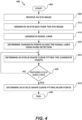
- FIG. 4 is a flow diagram of an example process 400 of eyelid shape estimation.
- the process 400 can be implemented by a hardware processor, for example a hardware process of an augmented reality device.
- the process 400 begins at block 404.
- an eye image is received.
- the eye image can be received from a variety of sources including an image capture device, a head mounted display system, a server, a non-transitory computer-readable medium, or a client computing device (e.g., a smartphone).
- the eye image can include eyelids 104, sclera 108 (the "white" of the eye), iris 112, and pupil 116 of an eye 100.
- an eye-box 120 can be generated over the eye 100 in the eye image.
- the eye-box 120 can be generated over the eye 100 in the eye image by overlaying the eye-box 120 over the eye 100 in the eye image.
- the eye-box 120 can be overlaid on the eye image by mapping the eye-box 120 to particular portions of the eye image.
- the eye-box 120 can be overlaid on the eye image computationally by a display system such as a head mounted display system.
- the eye-box 120 can be overlaid on the eye 100 in the eye image after a limbic boundary 112a or an approximation of the limbic boundary 112a is determined.
- the eye-box 120 can be overlaid such that the limbic boundary 112a is inside the boundary of the eye-box 120 overlaid on the eye image.
- the region of the iris 112 not covered by the eyelids 104 can be inside the boundary of the eye-box 120.
- block 412 is optional, because the eye image may include only the particular portions of the eye 100 used for eyelid shape estimation.
- one or more edges of the eye image function similarly to respective edges of an eye-box 120.
- the eye-box 120 is rectangular in shape.
- the eye-box 120 can be sized so as to be a minimum size bounding box that includes the entire iris 112.
- the eye-box 120 is shaped so that vertical edges 124a1, 124a2 of the eye-box 120 in FIGS. 1-2 are tangent to the outermost portions of the limbic boundary 112a of the iris 112. Accordingly, the shape of the eye-box 120 can change based on the edge of the upper eyelid 104a or lower eyelid 104b that is occluding the iris 112.
- block 412 can be optional.
- the eye image received can include only portions of the eye 100.
- the eye image can include portions of the eyelids 104, the sclera 108, the iris 112, and pupil 116 of the eye 100.
- the eye-box 120 can include the region of the iris 112 not covered by the eyelids 104. If the limbic boundary 112a or a portion of the limbic boundary 112a is inside the boundary of the eye-box 120, generating an eye-box 120 over the eye 100 in the eye image may be optional. Edges of the eye image can be considered as edges of the eye-box 120.
- the eye image received can be considered to be inside an eye-box 120 with edges corresponding to edges of the eye image.
- a plurality of radial lines 128a are generated from the pupil 116 (e.g., emanating from the center or around the center of the pupil 116) towards the top edge 124b1 of the eye-box 120 (for the upper eyelid 104a) or towards the bottom edge 124b2 of the eye-box 120 (for the lower eyelid 104b).
- a radial line 128a can be a line from the first pixel of the horizontal edge 124b1 closer to the upper eyelid 104a to the last pixel of the horizontal edge 124b2 closer to the lower eyelid 104b.
- a radial line 128a can be a line from the second pixel of the horizontal edge 124b 1 closer to the upper eyelid 104a to the n-1 pixel of the horizontal edge 124b2 closer to the lower eyelid 104b, where n denotes the width of the eye-box 120.
- the number of radial lines 128a may be as many as the width of the image, measured in pixels, or it may be a subsampling of this width. For example, a sampling process can be used to select certain radial lines to be used for eyelid shape estimation so that sufficient lines cross the eyelids to provide a good fit to the eyelid shape.
- the number of radial lines 128a can be optimized to be the minimal number of lines (e.g., three) that allow the eyelid shape to be estimated within a certain error threshold.
- the number of lines can be representative of the typical angular range subtended by an eyelid in an eye image, which is typically less than 180 degrees (for each eyelid).
- candidate points 136a or 136b can be determined for the plurality of radial lines 128a.
- the candidate points 136a or 136b are determined using edge detection.
- Edge detection can be applied by various edge detectors, edge detection algorithms, or filters.
- a Canny Edge detector can be applied to the image to detect edges in lines of the image. Edges are points located along a line that correspond to the local maximum derivatives.
- the detected points can be referred to as candidate points.
- the edge detector can also detect and exclude points of non-interest from the candidate points. For example, points along the pupillary boundary 116a or the limbic boundary 112a can be excluded from the candidate points.
- filters can be applied to the eye image to filter high-frequency noise. For example, a morphological open filter can be applied to the eye image.
- an eyelid shape curve is fitted to the candidate points.
- the eyelid shape curve is a parabolic fit curve 140a that is parabolic in shape.
- a parabola can be fitted to pass through three (or more) candidate points 136a. For example, a random subset of three candidate points 136a is drawn from the list of candidate points 136a. The random subset can be selected via a random sampling process or method.
- a parabolic fit 140a can be made using the candidate points in the random subset.
- a parabolic fit curve 140c shows a fit of the lower eyelid 104b using a random subset of the candidate points 136b.
- the eyelid shape curve is scored and compared to a score threshold.
- the score threshold can indicate an accurate estimation of the eyelid 104 shape within a certain error threshold.
- the Sobel derivative can be used to score the eyelid shape curve.
- the eyelid shape curve can be scored by summing the Sobel derivative along each candidate point 136a or 136b along the eyelid shape curve.
- the eyelid shape curve is scored by counting the number of candidate points 136a or 136b in total which are intersected by or sufficiently close to, e.g., within a number of pixels the eyelid shape curve. If the eyelid shape curve determined at block 424 is not a preferred eyelid shape curve, the block 424 is repeated. If the eyelid shape curve determined at block 4224 is a preferred eyelid shape curve, the process 400 proceeds to block 432.
- the fitting of the eyelid shape curve can optionally be repeated using inlier points.
- Such a refitting process may provide a more accurate estimation of an eyelid shape as compared to the actual measurement of the eyelid 104.
- the eyelid shape curve fitted by the refitting process can be determined to be most representative of the eyelid boundary and selected as that eyelid boundary. Thereafter, at block 436, the process 400 ends.
- FIG. 5 is a flow diagram of another example process 500 of eyelid shape estimation.
- the process 500 may be implemented by a hardware processor.
- the process 500 begins at block 504.
- an eye image is received.
- the eye image can be received from a variety of sources including, but not limited to: an image capture device, a head mounted display system, a server, a non-transitory computer-readable medium, or a client computing device (e.g., a smartphone).
- edge detection can be applied to the eye image to determine candidate points 136a or 136b.
- Edge detection can be applied by various edge detectors, edge detection algorithms, or filters.
- a Canny Edge detector can be applied to the image to detect edges in lines of the image. Edges can be points located along a line that correspond to the local maximum derivatives. The detected points can be referred to as candidate points 136a or 136b.
- the edge detector can also detect and exclude points of non-interest from the candidate points. For example, points along a pupillary boundary 116a or a limbic boundary 112a can be excluded from the candidate points 136a or 136b.
- filters can be applied to the eye image to filter high-frequency noise. For example, a morphological filter can be applied to the eye image.
- an eyelid shape curve 140a-140d can be fitted to the candidate points 136a or 136b.
- the eyelid shape curve 140a-140d can be fitted in accordance with various fitting processes as described above with reference to FIG. 3 .
- the process 500 ends.
- the processes 400 or 500 may be performed by a hardware processor of a head mounted display system.
- a remote computing device with computer-executable instructions can cause the head mounted display system to perform the processes 400 or 500.
- elements may occur in sequences other than as described above.
- candidate points 136a or 136b it may be advantageous to exclude potential candidate points along a pupillary boundary 116a or a limbic boundary 112a as candidate points 136a or 136b.
- Potential candidate points on or within a threshold distance (e.g., 2 pixels) of the pupillary boundary 116a or the limbic boundary 112a can be excluded as candidate points 136a or 136b.
- the remaining candidate points 136a or 136b can be used to determine the upper eyelid shape or the lower eyelid shape. If candidate points 136a or 136b used to determine an eyelid shape include points along the pupillary boundary 116a or the limbic boundary 112a, the eyelid shape determined may not be accurately.
- the candidate points may have to be sampled multiple times to determine multiple possible eyelid shape curves for an eyelid. Determining multiple possible eyelid shape curves for an eyelid requires more calculations and can be less efficient.
- FIG. 6 is a flow diagram of an example process 600 of eyelid shape estimation that excludes potential candidate points along a pupillary boundary or a limbic boundary as candidate points.
- the process 600 starts at 604.
- an eye image is received.
- the eye image can be received from an image capture device, a head mounted display system, a server, a non-transitory computer-readable medium, or a client computing device (e.g., a smartphone).
- a limbic boundary 112a in the eye image or a pupillary boundary 116a in the eye image can be received or determined at block 608.
- the eye image can be optionally processed with a filter to remove high frequency noise (e.g., a morphological open filter).
- edges in the eye image can be detected using an edge detector.
- the edges in the eye image may generally be representative of the pupillary boundary 116a, the limbic boundary 112a, and the eyelids 104.
- the edge detector can be a Canny edge detector.
- the edges in the eye image can be local maximum derivatives in the eye image. In some implementations, the local maximum derivatives can be pre-computed and stored in a look-up table.
- a plurality of radial lines 128a are generated inside the eye-box 120.
- the radial lines 128a emanate from the center of the pupil 116 towards the top edge 124b1 of the eye-box 120 and can be used to determine the upper eyelid 104a.
- candidate points 136a are determined for the plurality of radial lines 128a.
- a candidate point 136a of a radial line 128a is a point of the radial line 128a that intersects an edge in the eye image.
- the candidate point 136a are determined using an edge detector.
- the candidate point 136a in the eye image have a local maximum derivative in the eye image that can be optionally stored in a look-up table.
- the potential candidate point can be excluded from the candidate points 136a.
- the potential candidate point can be on or within a threshold distance (e.g., 2 pixels) of the pupillary boundary 116a or the limbic boundary 112a.
- the remaining candidate points 136a can be used to determine the upper eyelid 104a.
- a different subset of candidate points 136a can be used to determine the eyelid shape curve. These operations can be repeated for a number of iterations. The number of iterations can be a fixed number, or the operations can be iterated until an eyelid shape curve with more than a minimum number of inlier candidate points is found.
- An inlier candidate point can be a candidate point 136a that is within a threshold distance (e.g., a number of pixels) of the eyelid shape curve.
- the eyelid shape curve with a large score can be selected as the initial candidate eyelid shape curve.
- the initial candidate eyelid shape curve has a score that is sufficiently high (e.g., above a threshold) to be considered to accurately represent the eyelid shape.
- inliers to the initial eyelid shape candidate curve can be identified.
- inliers can include candidate points 136a on or within a threshold distance (e.g., a number of pixels) of the initial eyelid shape candidate curve.
- the remaining candidate points are outliers and are discarded as not being representative of eyelid shape.
- a new eyelid shape curve (e.g., a new parabolic fit curve 140a) can be determined by fitting some or all of the inlier points.
- the resulting eyelid shape curve can be considered the best estimate for the shape of the eyelid.
- the process 600 can be repeated for the lower eyelid 104b.
- blocks 620, 624, 628, and 632 of the process 600 can be repeated for the lower eyelid 104b.
- the order of determining the upper eyelid 104a and the lower eyelid 104b can be different in different implementations.
- the shape of the upper eyelid 104a can be determined prior the shape of the lower eyelid 104b is determined.
- the shape of the lower eyelid 104b can be determined prior to the shape of the upper eyelid 104a is determined.
- the shape of the upper eyelid 104a and the shape of the lower eyelid 104b can be determined in parallel.
- the process 600 ends at block 636.
- the eyelid shape estimation techniques can be used for image classification of frames in a video (e.g., identifying the iris 112 of the eye), as well as for the localization of specific object types within one or more frames of the video (e.g., the location of the upper eyelid 104a).
- the eyelid shape estimation techniques can be applied to a video for the application of eye-tracking (e.g., determining the orientation or direction of an eye).
- a wearable display system can include a processor that performs eyelid shape estimation on video data acquired by an image capture device operatively coupled to (e.g., attached to or included in) the wearable display system.
- the image capture device may acquire video of the wearer's eye or other components of the wearer's body (e.g., a hand or a finger) for use in generating eye-boxes 120 or estimating eyelid shape based on the eyelid shape estimation techniques.
- a user device can be wearable, which may advantageously provide a more immersive virtual reality (VR), augmented reality (AR), experience, wherein digitally reproduced images or portions thereof are presented to a wearer in a manner wherein they seem to be, or may be perceived as, real.
- VR virtual reality
- AR augmented reality
- displays containing a stack of waveguides may be configured to be worn positioned in front of the eyes of a user, or viewer.
- the stack of waveguides may be utilized to provide three-dimensional perception to the eye/brain by using a plurality of waveguides to direct light from an image injection device (e.g., discrete displays or output ends of a multiplexed display which pipe image information via one or more optical fibers) to the viewer's eye at particular angles (and amounts of divergence) corresponding to the depth plane associated with a particular waveguide.
- an image injection device e.g., discrete displays or output ends of a multiplexed display which pipe image information via one or more optical fibers
- two stacks of waveguides may be utilized to provide different images to each eye.
- an augmented reality scene may be such that a wearer of an AR technology sees a real-world park-like setting featuring people, trees, buildings in the background, and a concrete platform.
- the wearer of the AR technology may also perceive that he "sees" a robot statue standing upon the real-world platform, and a cartoon-like avatar character flying by which seems to be a personification of a bumble bee, even though the robot statue and the bumble bee do not exist in the real world.
- the stack(s) of waveguides may be used to generate a light field corresponding to an input image and in some implementations, the wearable display comprises a wearable light field display. Examples of wearable display device and waveguide stacks for providing light field images are described in U.S. Patent Publication No. 2015/0016777 .
- FIG. 7 illustrates an example of a wearable display system 700 that can be used to present a VR, AR, or MR experience to a display system wearer or viewer 704.
- the wearable display system 700 may be programmed to perform any of the applications or embodiments described herein (e.g., eye-box generation or eyelid shape estimation).
- the display system 700 includes a display 708, and various mechanical and electronic modules and systems to support the functioning of that display 708.
- the display 708 may be coupled to a frame 712, which is wearable by the display system wearer or viewer 704 and which is configured to position the display 708 in front of the eyes of the wearer 704.
- the display 708 may be a light field display.
- a speaker 716 is coupled to the frame 712 and positioned adjacent the ear canal of the user in some embodiments, another speaker, not shown, is positioned adjacent the other ear canal of the user to provide for stereo/shapeable sound control.
- the display 708 is operatively coupled 720, such as by a wired lead or wireless connectivity, to a local data processing module 724 which may be mounted in a variety of configurations, such as fixedly attached to the frame 712, fixedly attached to a helmet or hat worn by the user, embedded in headphones, or otherwise removably attached to the user 704 (e.g., in a backpack-style configuration, in a belt-coupling style configuration).
- the local processing and data module 724 may comprise a hardware processor, as well as non-transitory digital memory, such as non-volatile memory e.g., flash memory, both of which may be utilized to assist in the processing, caching, and storage of data.
- the data include data (a) captured from sensors (which may be, e.g., operatively coupled to the frame 712 or otherwise attached to the wearer 704), such as image capture devices (such as cameras), microphones, inertial measurement units, accelerometers, compasses, GPS units, radio devices, and/or gyros; and/or (b) acquired and/or processed using remote processing module 728 and/or remote data repository 732, possibly for passage to the display 708 after such processing or retrieval.
- sensors which may be, e.g., operatively coupled to the frame 712 or otherwise attached to the wearer 704
- image capture devices such as cameras
- microphones such as cameras
- inertial measurement units such as cameras
- accelerometers compasses
- the local processing and data module 724 may be operatively coupled to the remote processing module 728 and remote data repository 732 by communication links 736, 740, such as via a wired or wireless communication links, such that these remote modules 728, 732 are operatively coupled to each other and available as resources to the local processing and data module 724.
- the image capture device(s) can be used to capture the eye images used in the eyelid shape estimation procedures.
- the remote processing module 728 may comprise one or more processors configured to analyze and process data and/or image information such as video information captured by an image capture device.
- the video data may be stored locally in the local processing and data module 724 and/or in the remote data repository 732.
- the remote data repository 732 may comprise a digital data storage facility, which may be available through the internet or other networking configuration in a "cloud" resource configuration.
- all data is stored and all computations are performed in the local processing and data module 724, allowing fully autonomous use from a remote module.
- the local processing and data module 724 and/or the remote processing module 728 are programmed to perform embodiments of generating an eye-box and estimating an eyelid shape as disclosed herein.
- the local processing and data module 724 and/or the remote processing module 728 can be programmed to perform embodiments described herein.
- the local processing and data module 724 and/or the remote processing module 728 can be programmed to use the eyelid shape estimation techniques disclosed herein in biometric extraction, for example to identify or authenticate the identity of the wearer 704, or in eye gaze or pose estimation, for example to determine a direction toward which each eye is looking.
- the image capture device can capture video for a particular application (e.g., video of the wearer's eye for an eye-tracking application or video of a wearer's hand or finger for a gesture identification application).
- the video can be analyzed using the eyelid estimation techniques by one or both of the processing modules 724, 728With this analysis, processing modules 724, 728 can perform eyelid shape estimation or detection and/or biometric extraction, eye pose determination, etc.
- off-loading at least some of the eyelid shape estimation to a remote processing module may improve efficiency or speed of the computations.
- the parameters for eyelid shape estimation e.g., weights, bias terms, random subset sampling factors, number, and size of filters (e.g., Sobel derivative operator), etc.
- the processing module 724 can extract and formulate the biometric information from an eye image received from an image capture device into a numerical representation.
- the processing module 724 can also perform numerical calculations to represent an eye-box as a transfer function that transforms the biometric information extracted from an eye image into an image processing result.
- the image processing result can be used for further processing, for example, in eyelid shape estimation method as described herein.
- the image processing result and the transfer function can both be stored in the remote data repository 732. While this illustrative example of image processing is processed with the processing module 724, in various implementations, the remote processing module 728 can perform such image processing of an eye image. Additionally, the processing modules 724, 728 can, together perform such image processing of an eye image.
- the results of the video analysis can be used by one or both of the processing modules 724, 728 for additional operations or processing.
- biometric identification, eye-tracking, recognition or classification of gestures, objects, poses, etc. may be used by the wearable display system 700.
- video of the wearer's eye(s) can be used for eyelid shape estimation, which, in turn, can be used by the processing modules 724, 728 to determine the direction of the gaze of the wearer 704 through the display 708.
- the processing modules 724, 728 of the wearable display system 700 can be programmed with one or more embodiments of eye-box generation or eyelid shape estimation to perform any of the video or image processing applications described herein.
- Each of the processes, methods, and algorithms described herein and/or depicted in the attached figures may be embodied in, and fully or partially automated by, code modules executed by one or more physical computing systems, hardware computer processors, application-specific circuitry, and/or electronic hardware configured to execute specific and particular computer instructions.
- computing systems can include general purpose computers (e.g., servers) programmed with specific computer instructions or special purpose computers, special purpose circuitry, and so forth.
- a code module may be compiled and linked into an executable program, installed in a dynamic link library, or may be written in an interpreted programming language.
- particular operations and methods may be performed by circuitry that is specific to a given function.
- a video may include many frames, with each frame having millions of pixels, and specifically programmed computer hardware is necessary to process the video data to provide a desired image processing task or application in a commercially reasonable amount of time.
- Code modules or any type of data may be stored on any type of non-transitory computer-readable medium, such as physical computer storage including hard drives, solid state memory, random access memory (RAM), read only memory (ROM), optical disc, volatile or non-volatile storage, combinations of the same and/or the like.
- the methods and modules (or data) may also be transmitted as generated data signals (e.g., as part of a carrier wave or other analog or digital propagated signal) on a variety of computer-readable transmission mediums, including wireless-based and wired/cable-based mediums, and may take a variety of forms (e.g., as part of a single or multiplexed analog signal, or as multiple discrete digital packets or frames).
- the results of the disclosed processes or process steps may be stored, persistently or otherwise, in any type of non-transitory, tangible computer storage or may be communicated via a computer-readable transmission medium.
- any processes, blocks, states, steps, or functionalities in flow diagrams described herein and/or depicted in the attached figures should be understood as potentially representing code modules, segments, or portions of code which include one or more executable instructions for implementing specific functions (e.g., logical or arithmetical) or steps in the process.
- the various processes, blocks, states, steps, or functionalities can be combined, rearranged, added to, deleted from, modified, or otherwise changed from the illustrative examples provided herein.
- additional or different computing systems or code modules may perform some or all of the functionalities described herein.
- the processes, methods, and systems may be implemented in a network (or distributed) computing environment.
- Network environments include enterprise-wide computer networks, intranets, local area networks (LAN), wide area networks (WAN), personal area networks (PAN), cloud computing networks, crowd-sourced computing networks, the Internet, and the World Wide Web.
- the network may be a wired or a wireless network or any other type of communication network.
Landscapes
- Engineering & Computer Science (AREA)
- Health & Medical Sciences (AREA)
- General Health & Medical Sciences (AREA)
- Physics & Mathematics (AREA)
- General Physics & Mathematics (AREA)
- Theoretical Computer Science (AREA)
- Human Computer Interaction (AREA)
- Multimedia (AREA)
- Oral & Maxillofacial Surgery (AREA)
- Computer Vision & Pattern Recognition (AREA)
- Ophthalmology & Optometry (AREA)
- Measurement Of The Respiration, Hearing Ability, Form, And Blood Characteristics Of Living Organisms (AREA)
- Image Analysis (AREA)
- Image Processing (AREA)
- Eye Examination Apparatus (AREA)
- Optics & Photonics (AREA)
- Geometry (AREA)
- Prostheses (AREA)
- Thermotherapy And Cooling Therapy Devices (AREA)
- Transition And Organic Metals Composition Catalysts For Addition Polymerization (AREA)
Applications Claiming Priority (2)
| Application Number | Priority Date | Filing Date | Title |
|---|---|---|---|
| US201562208142P | 2015-08-21 | 2015-08-21 | |
| PCT/US2016/047183 WO2017034861A1 (en) | 2015-08-21 | 2016-08-16 | Eyelid shape estimation |
Publications (3)
| Publication Number | Publication Date |
|---|---|
| EP3337383A1 EP3337383A1 (en) | 2018-06-27 |
| EP3337383A4 EP3337383A4 (en) | 2019-04-03 |
| EP3337383B1 true EP3337383B1 (en) | 2024-10-16 |
Family
ID=58100935
Family Applications (1)
| Application Number | Title | Priority Date | Filing Date |
|---|---|---|---|
| EP16839826.1A Active EP3337383B1 (en) | 2015-08-21 | 2016-08-16 | Eyelid shape estimation |
Country Status (10)
| Country | Link |
|---|---|
| US (2) | US10089526B2 (https=) |
| EP (1) | EP3337383B1 (https=) |
| JP (2) | JP2018523878A (https=) |
| KR (1) | KR102726941B1 (https=) |
| CN (1) | CN108135467A (https=) |
| AU (2) | AU2016310452B2 (https=) |
| CA (1) | CA2995756A1 (https=) |
| IL (2) | IL283014B (https=) |
| NZ (1) | NZ740746A (https=) |
| WO (1) | WO2017034861A1 (https=) |
Families Citing this family (30)
| Publication number | Priority date | Publication date | Assignee | Title |
|---|---|---|---|---|
| EP3337383B1 (en) | 2015-08-21 | 2024-10-16 | Magic Leap, Inc. | Eyelid shape estimation |
| KR102591552B1 (ko) | 2015-08-21 | 2023-10-18 | 매직 립, 인코포레이티드 | 눈 포즈 측정을 사용한 눈꺼풀 형상 추정 |
| EP3761232B1 (en) | 2015-10-16 | 2025-12-03 | Magic Leap, Inc. | Eye pose identification using eye features |
| CN107346422B (zh) * | 2017-06-30 | 2020-09-08 | 成都大学 | 一种基于眨眼检测的活体人脸识别方法 |
| CN111033442B (zh) * | 2017-09-01 | 2024-07-02 | 奇跃公司 | 用于稳健的生物特征应用的详细的眼睛形状模型 |
| US10521661B2 (en) | 2017-09-01 | 2019-12-31 | Magic Leap, Inc. | Detailed eye shape model for robust biometric applications |
| KR102902962B1 (ko) | 2018-01-17 | 2025-12-22 | 매직 립, 인코포레이티드 | 디스플레이 시스템들에서의 눈 회전 중심 결정, 깊이 평면 선택, 및 렌더 카메라 포지셔닝 |
| IL275824B2 (en) | 2018-01-17 | 2024-08-01 | Magic Leap Inc | Display systems and methods for determining registration between a display and a user's eyes |
| CN108573219B (zh) * | 2018-03-27 | 2022-03-29 | 上海电力学院 | 一种基于深度卷积神经网络的眼睑关键点精确定位方法 |
| EP3707643A4 (en) * | 2018-04-25 | 2020-11-18 | Beijing Didi Infinity Technology and Development Co., Ltd. | SYSTEMS AND METHODS FOR BLINKING ACTION RECOGNITION BASED ON FACIAL CHARACTERISTIC POINTS |
| US11567336B2 (en) | 2018-07-24 | 2023-01-31 | Magic Leap, Inc. | Display systems and methods for determining registration between display and eyes of user |
| CN112384127B (zh) * | 2018-07-27 | 2023-11-10 | 高雄医学大学 | 眼睑下垂检测方法及系统 |
| CN109190548B (zh) * | 2018-08-28 | 2021-04-20 | 武汉真元生物数据有限公司 | 基于gabor滤波的快速眼睑检测方法及系统 |
| US11141645B2 (en) | 2018-09-11 | 2021-10-12 | Real Shot Inc. | Athletic ball game using smart glasses |
| US11103763B2 (en) | 2018-09-11 | 2021-08-31 | Real Shot Inc. | Basketball shooting game using smart glasses |
| EP3914997A4 (en) | 2019-01-25 | 2022-10-12 | Magic Leap, Inc. | Eye-tracking using images having different exposure times |
| EP3973347B1 (en) | 2019-05-20 | 2025-03-26 | Magic Leap, Inc. | Systems and techniques for estimating eye pose |
| US11327341B2 (en) * | 2019-06-14 | 2022-05-10 | Johnson & Johnson Vision Care, Inc | Toric contact lens stabilization design based on thickness gradients orthogonal to eyelid margin |
| US11868525B2 (en) | 2019-07-16 | 2024-01-09 | Magic Leap, Inc. | Eye center of rotation determination with one or more eye tracking cameras |
| EP3804606B1 (en) * | 2019-10-07 | 2022-05-11 | Optos PLC | Ophthalmic imaging system |
| KR102294029B1 (ko) * | 2019-12-04 | 2021-08-26 | 서울대학교산학협력단 | 동공검출과 눈꺼풀 곡률을 이용한 시선 추적 장치 및 그 방법 |
| US11269181B2 (en) | 2019-12-09 | 2022-03-08 | Magic Leap, Inc. | Systems and methods for operating a head-mounted display system based on user identity |
| KR102893471B1 (ko) | 2020-03-18 | 2025-11-28 | 주식회사 케이티 | 눈 모양 분류 방법 및 장치 그리고 컴퓨터 프로그램 |
| CN113642364B (zh) * | 2020-05-11 | 2024-04-12 | 华为技术有限公司 | 人脸图像处理方法、装置、设备及计算机可读存储介质 |
| CN111714080B (zh) * | 2020-06-30 | 2021-03-23 | 重庆大学 | 一种基于眼动信息的疾病分类系统 |
| WO2022015847A1 (en) | 2020-07-15 | 2022-01-20 | Magic Leap, Inc. | Eye tracking using aspheric cornea model |
| US11861805B2 (en) * | 2021-09-22 | 2024-01-02 | Sony Group Corporation | Eyeball positioning for 3D head modeling |
| CN114445890A (zh) * | 2022-01-25 | 2022-05-06 | 深圳市英威诺科技有限公司 | 人脸脸型匹配方法、装置、设备及存储介质 |
| SE2250299A1 (en) | 2022-03-04 | 2023-09-05 | Tobii Ab | Eye openness |
| WO2024182845A1 (en) * | 2023-03-06 | 2024-09-12 | Newsouth Innovations Pty Limited | Eye models for mental state analysis |
Family Cites Families (113)
| Publication number | Priority date | Publication date | Assignee | Title |
|---|---|---|---|---|
| US5719951A (en) * | 1990-07-17 | 1998-02-17 | British Telecommunications Public Limited Company | Normalized image feature processing |
| US5291560A (en) | 1991-07-15 | 1994-03-01 | Iri Scan Incorporated | Biometric personal identification system based on iris analysis |
| US6222525B1 (en) | 1992-03-05 | 2001-04-24 | Brad A. Armstrong | Image controllers with sheet connected sensors |
| US6095989A (en) | 1993-07-20 | 2000-08-01 | Hay; Sam H. | Optical recognition methods for locating eyes |
| US6463176B1 (en) | 1994-02-02 | 2002-10-08 | Canon Kabushiki Kaisha | Image recognition/reproduction method and apparatus |
| US5583795A (en) | 1995-03-17 | 1996-12-10 | The United States Of America As Represented By The Secretary Of The Army | Apparatus for measuring eye gaze and fixation duration, and method therefor |
| US5670988A (en) | 1995-09-05 | 1997-09-23 | Interlink Electronics, Inc. | Trigger operated electronic device |
| US5774591A (en) | 1995-12-15 | 1998-06-30 | Xerox Corporation | Apparatus and method for recognizing facial expressions and facial gestures in a sequence of images |
| US6154559A (en) | 1998-10-01 | 2000-11-28 | Mitsubishi Electric Information Technology Center America, Inc. (Ita) | System for classifying an individual's gaze direction |
| AUPQ896000A0 (en) * | 2000-07-24 | 2000-08-17 | Seeing Machines Pty Ltd | Facial image processing system |
| EP1357831A2 (en) | 2001-02-09 | 2003-11-05 | Sensomotoric Instruments GmbH | Multidimensional eye tracking and position measurement system |
| US7505604B2 (en) | 2002-05-20 | 2009-03-17 | Simmonds Precision Prodcuts, Inc. | Method for detection and recognition of fog presence within an aircraft compartment using video images |
| JP4128837B2 (ja) * | 2002-09-30 | 2008-07-30 | 佐藤 淳 | 路面走行レーン検出装置 |
| US7756301B2 (en) | 2005-01-26 | 2010-07-13 | Honeywell International Inc. | Iris recognition system and method |
| US7593550B2 (en) * | 2005-01-26 | 2009-09-22 | Honeywell International Inc. | Distance iris recognition |
| US8098901B2 (en) * | 2005-01-26 | 2012-01-17 | Honeywell International Inc. | Standoff iris recognition system |
| KR20050025927A (ko) | 2003-09-08 | 2005-03-14 | 유웅덕 | 홍채인식을 위한 동공 검출 방법 및 형상기술자 추출방법과 그를 이용한 홍채 특징 추출 장치 및 그 방법과홍채인식 시스템 및 그 방법 |
| JP4506250B2 (ja) * | 2004-04-12 | 2010-07-21 | 日産自動車株式会社 | 上瞼検出装置 |
| USD514570S1 (en) | 2004-06-24 | 2006-02-07 | Microsoft Corporation | Region of a fingerprint scanning device with an illuminated ring |
| JP4529635B2 (ja) | 2004-10-22 | 2010-08-25 | 日産自動車株式会社 | 開閉眼判定装置 |
| JP4449723B2 (ja) * | 2004-12-08 | 2010-04-14 | ソニー株式会社 | 画像処理装置、画像処理方法、およびプログラム |
| US7746235B2 (en) * | 2005-03-10 | 2010-06-29 | Delphi Technologies, Inc. | System and method of detecting eye closure based on line angles |
| WO2006108017A2 (en) | 2005-04-04 | 2006-10-12 | Lc Technologies, Inc. | Explicit raytracing for gimbal-based gazepoint trackers |
| US7327860B2 (en) | 2005-05-04 | 2008-02-05 | West Virginia University | Conjunctival scans for personal identification |
| US10709610B2 (en) | 2006-01-20 | 2020-07-14 | Lensar, Inc. | Laser methods and systems for addressing conditions of the lens |
| US11090190B2 (en) * | 2013-10-15 | 2021-08-17 | Lensar, Inc. | Iris registration method and system |
| JP4738488B2 (ja) | 2006-03-03 | 2011-08-03 | ハネウェル・インターナショナル・インコーポレーテッド | 画像品質メトリックを有する虹彩認識システム |
| US7542210B2 (en) | 2006-06-29 | 2009-06-02 | Chirieleison Sr Anthony | Eye tracking head mounted display |
| US8077914B1 (en) | 2006-08-07 | 2011-12-13 | Arkady Kaplan | Optical tracking apparatus using six degrees of freedom |
| US7682026B2 (en) | 2006-08-22 | 2010-03-23 | Southwest Research Institute | Eye location and gaze detection system and method |
| WO2008091401A2 (en) | 2006-09-15 | 2008-07-31 | Retica Systems, Inc | Multimodal ocular biometric system and methods |
| US8433103B2 (en) | 2006-09-15 | 2013-04-30 | Identix Incorporated | Long distance multimodal biometric system and method |
| JP4895797B2 (ja) * | 2006-12-26 | 2012-03-14 | アイシン精機株式会社 | 瞼検出装置、瞼検出方法及びプログラム |
| JP4309927B2 (ja) * | 2007-03-14 | 2009-08-05 | 株式会社豊田中央研究所 | まぶた検出装置及びプログラム |
| JP4309928B2 (ja) * | 2007-03-15 | 2009-08-05 | アイシン精機株式会社 | 瞼検出装置、瞼検出方法、及び、プログラム |
| JP4307496B2 (ja) * | 2007-03-19 | 2009-08-05 | 株式会社豊田中央研究所 | 顔部位検出装置及びプログラム |
| JP4781467B2 (ja) | 2007-04-16 | 2011-09-28 | 富士通株式会社 | 画像処理方法、画像処理装置、画像処理システム及びコンピュータプログラム |
| FR2915301A1 (fr) | 2007-04-20 | 2008-10-24 | Groupe Ecoles Telecomm | Procede de comparaison d'images d'une biometrie entre au moi ns une image de reference et au moins une image de test dont on cherche a evaluer un degre de correlation avec l'image d e reference |
| EP2143041A4 (en) * | 2007-05-01 | 2011-05-25 | Compulink Man Ct Inc | PHOTODOCUMENTEGMENTATION METHOD AND METHOD |
| WO2009041963A1 (en) | 2007-09-24 | 2009-04-02 | University Of Notre Dame Du Lac | Iris recognition using consistency information |
| JP5097514B2 (ja) | 2007-11-22 | 2012-12-12 | 国立大学法人東京工業大学 | ワイヤ電極式イオナイザ |
| US20090252382A1 (en) * | 2007-12-06 | 2009-10-08 | University Of Notre Dame Du Lac | Segmentation of iris images using active contour processing |
| JP5262243B2 (ja) * | 2008-03-31 | 2013-08-14 | アイシン精機株式会社 | 眼開閉判別装置、及びプログラム |
| WO2010011785A1 (en) * | 2008-07-23 | 2010-01-28 | Indiana University Research & Technology Corporation | System and method for a non-cooperative iris image acquisition system |
| US8345922B2 (en) * | 2008-09-03 | 2013-01-01 | Denso Corporation | Apparatus for detecting a pupil, program for the same, and method for detecting a pupil |
| JP4623171B2 (ja) * | 2008-09-03 | 2011-02-02 | 株式会社デンソー | 瞳孔検出装置、瞳孔検出装置用プログラム及び瞳孔検出方法 |
| US8768014B2 (en) * | 2009-01-14 | 2014-07-01 | Indiana University Research And Technology Corp. | System and method for identifying a person with reference to a sclera image |
| JP5387007B2 (ja) | 2009-01-22 | 2014-01-15 | 日本電気株式会社 | 画像処理装置、生体認証装置、画像処理方法及びプログラム |
| JP5221436B2 (ja) * | 2009-04-02 | 2013-06-26 | トヨタ自動車株式会社 | 顔特徴点検出装置及びプログラム |
| WO2010129544A1 (en) | 2009-05-04 | 2010-11-11 | Duke University | Methods and computer program products for quantitative three-dimensional image correction and clinical parameter computation in optical coherence tomography |
| CN101692980B (zh) * | 2009-10-30 | 2011-06-08 | 深圳市汉华安道科技有限责任公司 | 疲劳驾驶检测方法及装置 |
| US8403479B2 (en) | 2009-12-17 | 2013-03-26 | Johnson & Johnson Vision Care, Inc. | Contact lens eye model |
| US8948467B2 (en) | 2010-08-06 | 2015-02-03 | Honeywell International Inc. | Ocular and iris processing system and method |
| US9092371B2 (en) * | 2010-09-02 | 2015-07-28 | The Aerospace Corporation | Signal parameter estimator |
| US9304319B2 (en) | 2010-11-18 | 2016-04-05 | Microsoft Technology Licensing, Llc | Automatic focus improvement for augmented reality displays |
| US10156722B2 (en) | 2010-12-24 | 2018-12-18 | Magic Leap, Inc. | Methods and systems for displaying stereoscopy with a freeform optical system with addressable focus for virtual and augmented reality |
| AU2011348122A1 (en) | 2010-12-24 | 2013-07-11 | Magic Leap Inc. | An ergonomic head mounted display device and optical system |
| JP4893862B1 (ja) * | 2011-03-11 | 2012-03-07 | オムロン株式会社 | 画像処理装置、および画像処理方法 |
| JP4893863B1 (ja) * | 2011-03-11 | 2012-03-07 | オムロン株式会社 | 画像処理装置、および画像処理方法 |
| US9020199B2 (en) * | 2011-04-19 | 2015-04-28 | Aisin Seiki Kabushiki Kaisha | Eyelid detection device, eyelid detection method, and recording medium |
| JP6316186B2 (ja) | 2011-05-06 | 2018-04-25 | マジック リープ, インコーポレイテッドMagic Leap,Inc. | 広範囲同時遠隔ディジタル提示世界 |
| US8854491B2 (en) | 2011-06-05 | 2014-10-07 | Apple Inc. | Metadata-assisted image filters |
| US9298995B2 (en) | 2011-07-11 | 2016-03-29 | Toyota Jidosha Kabushiki Kaisha | Red-eye determination device |
| EP2751609B1 (en) * | 2011-08-30 | 2017-08-16 | Microsoft Technology Licensing, LLC | Head mounted display with iris scan profiling |
| EP2760363A4 (en) | 2011-09-29 | 2015-06-24 | Magic Leap Inc | TACTILE GLOVE FOR HUMAN COMPUTER INTERACTION |
| US9215293B2 (en) | 2011-10-28 | 2015-12-15 | Magic Leap, Inc. | System and method for augmented and virtual reality |
| ITVR20110201A1 (it) | 2011-11-02 | 2013-05-03 | Milano Politecnico | Dispositivo per il monitoraggio della posizione e deimovimenti dell'occhio, particolarmente adatto per la radioterapia oculare |
| US8950867B2 (en) | 2011-11-23 | 2015-02-10 | Magic Leap, Inc. | Three dimensional virtual and augmented reality display system |
| CN102521576A (zh) * | 2011-12-16 | 2012-06-27 | 北京天诚盛业科技有限公司 | 一种虹膜定位方法 |
| CN102592260B (zh) * | 2011-12-26 | 2013-09-25 | 广州商景网络科技有限公司 | 证照图像裁剪方法及系统 |
| US9075453B2 (en) | 2011-12-29 | 2015-07-07 | Khalifa University of Science, Technology & Research (KUSTAR) | Human eye controlled computer mouse interface |
| CN102629319B (zh) * | 2012-03-27 | 2014-02-19 | 中国科学院自动化研究所 | 基于特定边界检测子的鲁棒虹膜区域分割方法 |
| WO2013152205A1 (en) | 2012-04-05 | 2013-10-10 | Augmented Vision Inc. | Wide-field of view (fov) imaging devices with active foveation capability |
| WO2013188464A1 (en) | 2012-06-11 | 2013-12-19 | Magic Leap, Inc. | Multiple depth plane three-dimensional display using a wave guide reflector array projector |
| US9671566B2 (en) | 2012-06-11 | 2017-06-06 | Magic Leap, Inc. | Planar waveguide apparatus with diffraction element(s) and system employing same |
| US9122926B2 (en) * | 2012-07-19 | 2015-09-01 | Honeywell International Inc. | Iris recognition using localized Zernike moments |
| KR20150054967A (ko) | 2012-09-11 | 2015-05-20 | 매직 립, 인코포레이티드 | 인체공학적 헤드 마운티드 디스플레이 디바이스 및 광학 시스템 |
| US9152847B2 (en) * | 2012-11-27 | 2015-10-06 | Adobe Systems Incorporated | Facial landmark localization by exemplar-based graph matching |
| US9224036B2 (en) | 2012-12-20 | 2015-12-29 | Google Inc. | Generating static scenes |
| KR102141992B1 (ko) | 2013-01-15 | 2020-08-06 | 매직 립, 인코포레이티드 | 초고해상도 스캐닝 섬유 디스플레이 |
| JP6318462B2 (ja) * | 2013-01-30 | 2018-05-09 | 株式会社ニコン | 表示装置 |
| IL308285B2 (en) | 2013-03-11 | 2024-11-01 | Magic Leap Inc | System and method for augmentation and virtual reality |
| US9424467B2 (en) | 2013-03-14 | 2016-08-23 | Disney Enterprises, Inc. | Gaze tracking and recognition with image location |
| US9417452B2 (en) | 2013-03-15 | 2016-08-16 | Magic Leap, Inc. | Display system and method |
| US9335547B2 (en) * | 2013-03-25 | 2016-05-10 | Seiko Epson Corporation | Head-mounted display device and method of controlling head-mounted display device |
| CN103164704B (zh) * | 2013-04-12 | 2016-05-11 | 山东师范大学 | 一种基于混合高斯模型的虹膜图像分割算法 |
| US10262462B2 (en) | 2014-04-18 | 2019-04-16 | Magic Leap, Inc. | Systems and methods for augmented and virtual reality |
| US9874749B2 (en) | 2013-11-27 | 2018-01-23 | Magic Leap, Inc. | Virtual and augmented reality systems and methods |
| JP6479785B2 (ja) | 2013-10-16 | 2019-03-06 | マジック リープ, インコーポレイテッドMagic Leap,Inc. | 調節可能な瞳孔間距離を有する仮想または拡張現実ヘッドセット |
| US9857591B2 (en) | 2014-05-30 | 2018-01-02 | Magic Leap, Inc. | Methods and system for creating focal planes in virtual and augmented reality |
| CN107272199B (zh) | 2013-11-27 | 2023-04-07 | 奇跃公司 | 虚拟和增强现实系统与方法 |
| WO2015103745A1 (en) * | 2014-01-08 | 2015-07-16 | Nokia Technologies Oy | An apparatus and associated methods for image capture |
| JP5956479B2 (ja) * | 2014-01-29 | 2016-07-27 | 株式会社東芝 | 表示装置及び視線推定装置 |
| KR102177133B1 (ko) | 2014-01-31 | 2020-11-10 | 매직 립, 인코포레이티드 | 멀티-포컬 디스플레이 시스템 및 방법 |
| CN106233189B (zh) | 2014-01-31 | 2020-06-26 | 奇跃公司 | 多焦点显示系统和方法 |
| US10203762B2 (en) | 2014-03-11 | 2019-02-12 | Magic Leap, Inc. | Methods and systems for creating virtual and augmented reality |
| USD759657S1 (en) | 2014-05-19 | 2016-06-21 | Microsoft Corporation | Connector with illumination region |
| NZ727350A (en) | 2014-05-30 | 2020-08-28 | Magic Leap Inc | Methods and systems for generating virtual content display with a virtual or augmented reality apparatus |
| USD752529S1 (en) | 2014-06-09 | 2016-03-29 | Comcast Cable Communications, Llc | Electronic housing with illuminated region |
| CN104537334B (zh) * | 2014-07-08 | 2019-09-10 | 珠海易胜电子技术有限公司 | 一种改善在非理想环境下虹膜识别性能的方法 |
| US9563805B2 (en) | 2014-09-02 | 2017-02-07 | Hong Kong Baptist University | Method and apparatus for eye gaze tracking |
| US9798383B2 (en) | 2014-09-19 | 2017-10-24 | Intel Corporation | Facilitating dynamic eye torsion-based eye tracking on computing devices |
| CN104680016A (zh) * | 2014-11-05 | 2015-06-03 | 河南科技大学 | 基于几何优化逼近的抛物线轮廓最小区域拟合方法 |
| CN104502329B (zh) * | 2014-12-28 | 2017-02-22 | 冶金自动化研究设计院 | 一种libs成分分析中元素最优工作曲线的建立方法 |
| US11263794B2 (en) | 2015-01-21 | 2022-03-01 | Chengdu Idealsee Technology Co., Ltd. | Binocular see-through AR head-mounted display device and information displaying method thereof |
| CN104793741A (zh) * | 2015-04-03 | 2015-07-22 | 深圳市虚拟现实科技有限公司 | 带眼球跟踪虚拟现实成像系统和方法 |
| CN105157563B (zh) * | 2015-04-28 | 2016-08-03 | 湖南大学 | 一种基于机器视觉的啤酒瓶口定位方法 |
| USD758367S1 (en) | 2015-05-14 | 2016-06-07 | Magic Leap, Inc. | Virtual reality headset |
| EP3337383B1 (en) * | 2015-08-21 | 2024-10-16 | Magic Leap, Inc. | Eyelid shape estimation |
| KR102591552B1 (ko) * | 2015-08-21 | 2023-10-18 | 매직 립, 인코포레이티드 | 눈 포즈 측정을 사용한 눈꺼풀 형상 추정 |
| EP3761232B1 (en) | 2015-10-16 | 2025-12-03 | Magic Leap, Inc. | Eye pose identification using eye features |
| USD805734S1 (en) | 2016-03-04 | 2017-12-26 | Nike, Inc. | Shirt |
| USD794288S1 (en) | 2016-03-11 | 2017-08-15 | Nike, Inc. | Shoe with illuminable sole light sequence |
-
2016
- 2016-08-16 EP EP16839826.1A patent/EP3337383B1/en active Active
- 2016-08-16 KR KR1020187008101A patent/KR102726941B1/ko active Active
- 2016-08-16 WO PCT/US2016/047183 patent/WO2017034861A1/en not_active Ceased
- 2016-08-16 JP JP2018509545A patent/JP2018523878A/ja not_active Withdrawn
- 2016-08-16 CA CA2995756A patent/CA2995756A1/en active Pending
- 2016-08-16 NZ NZ740746A patent/NZ740746A/en unknown
- 2016-08-16 AU AU2016310452A patent/AU2016310452B2/en active Active
- 2016-08-16 US US15/238,549 patent/US10089526B2/en active Active
- 2016-08-16 CN CN201680060757.7A patent/CN108135467A/zh active Pending
- 2016-08-16 IL IL283014A patent/IL283014B/en unknown
-
2018
- 2018-02-13 IL IL257504A patent/IL257504B/en active IP Right Grant
- 2018-09-28 US US16/146,228 patent/US10282611B2/en active Active
-
2021
- 2021-07-19 AU AU2021206783A patent/AU2021206783A1/en not_active Abandoned
-
2022
- 2022-02-08 JP JP2022017795A patent/JP2022051873A/ja active Pending
Non-Patent Citations (1)
| Title |
|---|
| SMITH MICHAEL DAVID: "REAL-TIME LOCATION AND PARAMETERIZATION OF EYES IN AN IMAGE SEQUENCE AND THE DETECTION OF THEIR POINT-OF-GAZE", THESIS FOR THE DEGREE OF MASTER OF APPLIED SCIENCE, 22 April 1998 (1998-04-22), Vancouver, Canada, pages 1 - 169, XP055814966, Retrieved from the Internet <URL:https://open.library.ubc.ca/cIRcle/collections/ubctheses/831/items/1.0065130> [retrieved on 20210617] * |
Also Published As
| Publication number | Publication date |
|---|---|
| NZ740746A (en) | 2019-08-30 |
| AU2016310452B2 (en) | 2021-04-22 |
| US20170053166A1 (en) | 2017-02-23 |
| IL283014B (en) | 2022-07-01 |
| EP3337383A1 (en) | 2018-06-27 |
| IL257504B (en) | 2021-05-31 |
| KR102726941B1 (ko) | 2024-11-05 |
| IL283014A (en) | 2021-06-30 |
| JP2018523878A (ja) | 2018-08-23 |
| CA2995756A1 (en) | 2017-03-02 |
| JP2022051873A (ja) | 2022-04-01 |
| AU2021206783A1 (en) | 2021-08-12 |
| US20190034692A1 (en) | 2019-01-31 |
| AU2016310452A1 (en) | 2018-04-12 |
| KR20180044346A (ko) | 2018-05-02 |
| CN108135467A (zh) | 2018-06-08 |
| IL257504A (en) | 2018-04-30 |
| US10089526B2 (en) | 2018-10-02 |
| WO2017034861A1 (en) | 2017-03-02 |
| EP3337383A4 (en) | 2019-04-03 |
| US10282611B2 (en) | 2019-05-07 |
Similar Documents
| Publication | Publication Date | Title |
|---|---|---|
| EP3337383B1 (en) | Eyelid shape estimation | |
| US11538280B2 (en) | Eyelid shape estimation using eye pose measurement | |
| AU2021240222B2 (en) | Eye pose identification using eye features | |
| US11227158B2 (en) | Detailed eye shape model for robust biometric applications |
Legal Events
| Date | Code | Title | Description |
|---|---|---|---|
| STAA | Information on the status of an ep patent application or granted ep patent |
Free format text: STATUS: THE INTERNATIONAL PUBLICATION HAS BEEN MADE |
|
| PUAI | Public reference made under article 153(3) epc to a published international application that has entered the european phase |
Free format text: ORIGINAL CODE: 0009012 |
|
| STAA | Information on the status of an ep patent application or granted ep patent |
Free format text: STATUS: REQUEST FOR EXAMINATION WAS MADE |
|
| 17P | Request for examination filed |
Effective date: 20180314 |
|
| AK | Designated contracting states |
Kind code of ref document: A1 Designated state(s): AL AT BE BG CH CY CZ DE DK EE ES FI FR GB GR HR HU IE IS IT LI LT LU LV MC MK MT NL NO PL PT RO RS SE SI SK SM TR |
|
| AX | Request for extension of the european patent |
Extension state: BA ME |
|
| DAV | Request for validation of the european patent (deleted) | ||
| DAX | Request for extension of the european patent (deleted) | ||
| A4 | Supplementary search report drawn up and despatched |
Effective date: 20190306 |
|
| RIC1 | Information provided on ipc code assigned before grant |
Ipc: G06K 9/00 20060101AFI20190228BHEP |
|
| STAA | Information on the status of an ep patent application or granted ep patent |
Free format text: STATUS: EXAMINATION IS IN PROGRESS |
|
| 17Q | First examination report despatched |
Effective date: 20210623 |
|
| REG | Reference to a national code |
Ref legal event code: R079 Ref country code: DE Ref legal event code: R079 Ref document number: 602016089880 Country of ref document: DE Free format text: PREVIOUS MAIN CLASS: A61B0003100000 Ipc: G06V0040180000 |
|
| GRAP | Despatch of communication of intention to grant a patent |
Free format text: ORIGINAL CODE: EPIDOSNIGR1 |
|
| STAA | Information on the status of an ep patent application or granted ep patent |
Free format text: STATUS: GRANT OF PATENT IS INTENDED |
|
| RIC1 | Information provided on ipc code assigned before grant |
Ipc: G06V 40/18 20220101AFI20231127BHEP |
|
| INTG | Intention to grant announced |
Effective date: 20231220 |
|
| GRAJ | Information related to disapproval of communication of intention to grant by the applicant or resumption of examination proceedings by the epo deleted |
Free format text: ORIGINAL CODE: EPIDOSDIGR1 |
|
| STAA | Information on the status of an ep patent application or granted ep patent |
Free format text: STATUS: EXAMINATION IS IN PROGRESS |
|
| GRAP | Despatch of communication of intention to grant a patent |
Free format text: ORIGINAL CODE: EPIDOSNIGR1 |
|
| STAA | Information on the status of an ep patent application or granted ep patent |
Free format text: STATUS: GRANT OF PATENT IS INTENDED |
|
| INTG | Intention to grant announced |
Effective date: 20240506 |
|
| GRAS | Grant fee paid |
Free format text: ORIGINAL CODE: EPIDOSNIGR3 |
|
| GRAA | (expected) grant |
Free format text: ORIGINAL CODE: 0009210 |
|
| STAA | Information on the status of an ep patent application or granted ep patent |
Free format text: STATUS: THE PATENT HAS BEEN GRANTED |
|
| AK | Designated contracting states |
Kind code of ref document: B1 Designated state(s): AL AT BE BG CH CY CZ DE DK EE ES FI FR GB GR HR HU IE IS IT LI LT LU LV MC MK MT NL NO PL PT RO RS SE SI SK SM TR |
|
| REG | Reference to a national code |
Ref country code: GB Ref legal event code: FG4D |
|
| REG | Reference to a national code |
Ref country code: CH Ref legal event code: EP |
|
| REG | Reference to a national code |
Ref country code: IE Ref legal event code: FG4D |
|
| REG | Reference to a national code |
Ref country code: DE Ref legal event code: R096 Ref document number: 602016089880 Country of ref document: DE |
|
| P01 | Opt-out of the competence of the unified patent court (upc) registered |
Free format text: CASE NUMBER: APP_54835/2024 Effective date: 20241004 |
|
| REG | Reference to a national code |
Ref country code: NL Ref legal event code: FP |
|
| REG | Reference to a national code |
Ref country code: LT Ref legal event code: MG9D |
|
| REG | Reference to a national code |
Ref country code: AT Ref legal event code: MK05 Ref document number: 1733567 Country of ref document: AT Kind code of ref document: T Effective date: 20241016 |
|
| PG25 | Lapsed in a contracting state [announced via postgrant information from national office to epo] |
Ref country code: IS Free format text: LAPSE BECAUSE OF FAILURE TO SUBMIT A TRANSLATION OF THE DESCRIPTION OR TO PAY THE FEE WITHIN THE PRESCRIBED TIME-LIMIT Effective date: 20250216 Ref country code: PT Free format text: LAPSE BECAUSE OF FAILURE TO SUBMIT A TRANSLATION OF THE DESCRIPTION OR TO PAY THE FEE WITHIN THE PRESCRIBED TIME-LIMIT Effective date: 20250217 Ref country code: HR Free format text: LAPSE BECAUSE OF FAILURE TO SUBMIT A TRANSLATION OF THE DESCRIPTION OR TO PAY THE FEE WITHIN THE PRESCRIBED TIME-LIMIT Effective date: 20241016 |
|
| PG25 | Lapsed in a contracting state [announced via postgrant information from national office to epo] |
Ref country code: FI Free format text: LAPSE BECAUSE OF FAILURE TO SUBMIT A TRANSLATION OF THE DESCRIPTION OR TO PAY THE FEE WITHIN THE PRESCRIBED TIME-LIMIT Effective date: 20241016 |
|
| PG25 | Lapsed in a contracting state [announced via postgrant information from national office to epo] |
Ref country code: BG Free format text: LAPSE BECAUSE OF FAILURE TO SUBMIT A TRANSLATION OF THE DESCRIPTION OR TO PAY THE FEE WITHIN THE PRESCRIBED TIME-LIMIT Effective date: 20241016 |
|
| PG25 | Lapsed in a contracting state [announced via postgrant information from national office to epo] |
Ref country code: ES Free format text: LAPSE BECAUSE OF FAILURE TO SUBMIT A TRANSLATION OF THE DESCRIPTION OR TO PAY THE FEE WITHIN THE PRESCRIBED TIME-LIMIT Effective date: 20241016 |
|
| PG25 | Lapsed in a contracting state [announced via postgrant information from national office to epo] |
Ref country code: NO Free format text: LAPSE BECAUSE OF FAILURE TO SUBMIT A TRANSLATION OF THE DESCRIPTION OR TO PAY THE FEE WITHIN THE PRESCRIBED TIME-LIMIT Effective date: 20250116 |
|
| PG25 | Lapsed in a contracting state [announced via postgrant information from national office to epo] |
Ref country code: AT Free format text: LAPSE BECAUSE OF FAILURE TO SUBMIT A TRANSLATION OF THE DESCRIPTION OR TO PAY THE FEE WITHIN THE PRESCRIBED TIME-LIMIT Effective date: 20241016 Ref country code: LV Free format text: LAPSE BECAUSE OF FAILURE TO SUBMIT A TRANSLATION OF THE DESCRIPTION OR TO PAY THE FEE WITHIN THE PRESCRIBED TIME-LIMIT Effective date: 20241016 Ref country code: GR Free format text: LAPSE BECAUSE OF FAILURE TO SUBMIT A TRANSLATION OF THE DESCRIPTION OR TO PAY THE FEE WITHIN THE PRESCRIBED TIME-LIMIT Effective date: 20250117 |
|
| PG25 | Lapsed in a contracting state [announced via postgrant information from national office to epo] |
Ref country code: PL Free format text: LAPSE BECAUSE OF FAILURE TO SUBMIT A TRANSLATION OF THE DESCRIPTION OR TO PAY THE FEE WITHIN THE PRESCRIBED TIME-LIMIT Effective date: 20241016 |
|
| PG25 | Lapsed in a contracting state [announced via postgrant information from national office to epo] |
Ref country code: RS Free format text: LAPSE BECAUSE OF FAILURE TO SUBMIT A TRANSLATION OF THE DESCRIPTION OR TO PAY THE FEE WITHIN THE PRESCRIBED TIME-LIMIT Effective date: 20250116 |
|
| PG25 | Lapsed in a contracting state [announced via postgrant information from national office to epo] |
Ref country code: SM Free format text: LAPSE BECAUSE OF FAILURE TO SUBMIT A TRANSLATION OF THE DESCRIPTION OR TO PAY THE FEE WITHIN THE PRESCRIBED TIME-LIMIT Effective date: 20241016 |
|
| PG25 | Lapsed in a contracting state [announced via postgrant information from national office to epo] |
Ref country code: DK Free format text: LAPSE BECAUSE OF FAILURE TO SUBMIT A TRANSLATION OF THE DESCRIPTION OR TO PAY THE FEE WITHIN THE PRESCRIBED TIME-LIMIT Effective date: 20241016 |
|
| REG | Reference to a national code |
Ref country code: DE Ref legal event code: R097 Ref document number: 602016089880 Country of ref document: DE |
|
| PG25 | Lapsed in a contracting state [announced via postgrant information from national office to epo] |
Ref country code: EE Free format text: LAPSE BECAUSE OF FAILURE TO SUBMIT A TRANSLATION OF THE DESCRIPTION OR TO PAY THE FEE WITHIN THE PRESCRIBED TIME-LIMIT Effective date: 20241016 |
|
| PG25 | Lapsed in a contracting state [announced via postgrant information from national office to epo] |
Ref country code: RO Free format text: LAPSE BECAUSE OF FAILURE TO SUBMIT A TRANSLATION OF THE DESCRIPTION OR TO PAY THE FEE WITHIN THE PRESCRIBED TIME-LIMIT Effective date: 20241016 |
|
| PG25 | Lapsed in a contracting state [announced via postgrant information from national office to epo] |
Ref country code: SK Free format text: LAPSE BECAUSE OF FAILURE TO SUBMIT A TRANSLATION OF THE DESCRIPTION OR TO PAY THE FEE WITHIN THE PRESCRIBED TIME-LIMIT Effective date: 20241016 |
|
| PG25 | Lapsed in a contracting state [announced via postgrant information from national office to epo] |
Ref country code: CZ Free format text: LAPSE BECAUSE OF FAILURE TO SUBMIT A TRANSLATION OF THE DESCRIPTION OR TO PAY THE FEE WITHIN THE PRESCRIBED TIME-LIMIT Effective date: 20241016 |
|
| PG25 | Lapsed in a contracting state [announced via postgrant information from national office to epo] |
Ref country code: IT Free format text: LAPSE BECAUSE OF FAILURE TO SUBMIT A TRANSLATION OF THE DESCRIPTION OR TO PAY THE FEE WITHIN THE PRESCRIBED TIME-LIMIT Effective date: 20241016 |
|
| PGFP | Annual fee paid to national office [announced via postgrant information from national office to epo] |
Ref country code: NL Payment date: 20250723 Year of fee payment: 10 |
|
| PLBE | No opposition filed within time limit |
Free format text: ORIGINAL CODE: 0009261 |
|
| STAA | Information on the status of an ep patent application or granted ep patent |
Free format text: STATUS: NO OPPOSITION FILED WITHIN TIME LIMIT |
|
| PG25 | Lapsed in a contracting state [announced via postgrant information from national office to epo] |
Ref country code: SE Free format text: LAPSE BECAUSE OF FAILURE TO SUBMIT A TRANSLATION OF THE DESCRIPTION OR TO PAY THE FEE WITHIN THE PRESCRIBED TIME-LIMIT Effective date: 20241016 |
|
| 26N | No opposition filed |
Effective date: 20250717 |
|
| PGFP | Annual fee paid to national office [announced via postgrant information from national office to epo] |
Ref country code: DE Payment date: 20250724 Year of fee payment: 10 |
|
| PGFP | Annual fee paid to national office [announced via postgrant information from national office to epo] |
Ref country code: BE Payment date: 20250723 Year of fee payment: 10 Ref country code: GB Payment date: 20250724 Year of fee payment: 10 |
|
| PGFP | Annual fee paid to national office [announced via postgrant information from national office to epo] |
Ref country code: FR Payment date: 20250725 Year of fee payment: 10 |
|
| REG | Reference to a national code |
Ref country code: CH Ref legal event code: H13 Free format text: ST27 STATUS EVENT CODE: U-0-0-H10-H13 (AS PROVIDED BY THE NATIONAL OFFICE) Effective date: 20260324 |
|
| PG25 | Lapsed in a contracting state [announced via postgrant information from national office to epo] |
Ref country code: MC Free format text: LAPSE BECAUSE OF FAILURE TO SUBMIT A TRANSLATION OF THE DESCRIPTION OR TO PAY THE FEE WITHIN THE PRESCRIBED TIME-LIMIT Effective date: 20241016 |
|
| PG25 | Lapsed in a contracting state [announced via postgrant information from national office to epo] |
Ref country code: LU Free format text: LAPSE BECAUSE OF NON-PAYMENT OF DUE FEES Effective date: 20250816 |