EP3337214A1 - Radio communication device, transmitting method and computer program - Google Patents
Radio communication device, transmitting method and computer program Download PDFInfo
- Publication number
- EP3337214A1 EP3337214A1 EP16836982.5A EP16836982A EP3337214A1 EP 3337214 A1 EP3337214 A1 EP 3337214A1 EP 16836982 A EP16836982 A EP 16836982A EP 3337214 A1 EP3337214 A1 EP 3337214A1
- Authority
- EP
- European Patent Office
- Prior art keywords
- transmission
- destinations
- update
- counter value
- basis
- Prior art date
- Legal status (The legal status is an assumption and is not a legal conclusion. Google has not performed a legal analysis and makes no representation as to the accuracy of the status listed.)
- Granted
Links
Images








Classifications
-
- H—ELECTRICITY
- H04—ELECTRIC COMMUNICATION TECHNIQUE
- H04W—WIRELESS COMMUNICATION NETWORKS
- H04W72/00—Local resource management
- H04W72/12—Wireless traffic scheduling
- H04W72/1221—Wireless traffic scheduling based on age of data to be sent
-
- H—ELECTRICITY
- H04—ELECTRIC COMMUNICATION TECHNIQUE
- H04L—TRANSMISSION OF DIGITAL INFORMATION, e.g. TELEGRAPHIC COMMUNICATION
- H04L12/00—Data switching networks
- H04L12/02—Details
- H04L12/16—Arrangements for providing special services to substations
- H04L12/18—Arrangements for providing special services to substations for broadcast or conference, e.g. multicast
- H04L12/1863—Arrangements for providing special services to substations for broadcast or conference, e.g. multicast comprising mechanisms for improved reliability, e.g. status reports
- H04L12/1868—Measures taken after transmission, e.g. acknowledgments
-
- H—ELECTRICITY
- H04—ELECTRIC COMMUNICATION TECHNIQUE
- H04W—WIRELESS COMMUNICATION NETWORKS
- H04W16/00—Network planning, e.g. coverage or traffic planning tools; Network deployment, e.g. resource partitioning or cells structures
- H04W16/14—Spectrum sharing arrangements between different networks
-
- H—ELECTRICITY
- H04—ELECTRIC COMMUNICATION TECHNIQUE
- H04W—WIRELESS COMMUNICATION NETWORKS
- H04W24/00—Supervisory, monitoring or testing arrangements
- H04W24/08—Testing, supervising or monitoring using real traffic
-
- H—ELECTRICITY
- H04—ELECTRIC COMMUNICATION TECHNIQUE
- H04W—WIRELESS COMMUNICATION NETWORKS
- H04W74/00—Wireless channel access
- H04W74/08—Non-scheduled access, e.g. ALOHA
-
- H—ELECTRICITY
- H04—ELECTRIC COMMUNICATION TECHNIQUE
- H04W—WIRELESS COMMUNICATION NETWORKS
- H04W74/00—Wireless channel access
- H04W74/08—Non-scheduled access, e.g. ALOHA
- H04W74/0808—Non-scheduled access, e.g. ALOHA using carrier sensing, e.g. carrier sense multiple access [CSMA]
- H04W74/0825—Non-scheduled access, e.g. ALOHA using carrier sensing, e.g. carrier sense multiple access [CSMA] with collision detection
-
- H—ELECTRICITY
- H04—ELECTRIC COMMUNICATION TECHNIQUE
- H04W—WIRELESS COMMUNICATION NETWORKS
- H04W4/00—Services specially adapted for wireless communication networks; Facilities therefor
- H04W4/06—Selective distribution of broadcast services, e.g. multimedia broadcast multicast service [MBMS]; Services to user groups; One-way selective calling services
Definitions
- the present invention relates to a wireless communication device, a transmission method and a computer program.
- a listen before talk (LBT) technology is known in the related art.
- LBT listen before talk
- a wireless communication device senses the usage status of the frequency band before performing transmission and determines whether or not it is possible to perform transmission on the basis of the carrier-sense result in order not to cause radio interference with other wireless communication devices that share the frequency band.
- Wi-Fi registered trademark
- carrier-sense is performed during a fixed waiting time plus a randomly determined waiting time to stochastically avoid collisions (for example, see Non-Patent Literature 1).
- the randomly determined waiting time is called a backoff time (Backoff).
- Fig. 15 is an explanatory diagram of a related-art Wi-Fi LBT technology.
- a wireless LAN device before performing transmission, a wireless LAN device performs carrier-sense during a time which is the sum of a fixed waiting time (a distributed inter-frame space (DIFS)) and a randomly determined waiting time (a backoff time).
- the backoff time is determined according to a backoff value randomly selected from a range of 0 to a contention window (CW) with a uniform probability.
- DIFS distributed inter-frame space
- CW contention window
- the CW is increased twofold each time. An initial value of the CW is 15 and a maximum value of the CW is 1023.
- the wireless LAN device transmits data to a single destination, performs management on whether or not an ACK signal has been received from the single destination, and determines a backoff value for a next transmission according to whether or not an ACK signal has been received from the single destination.
- the maximum time length of data transmission is set as a maximum transmit duration (MTD). In Japan, the maximum time length is 4 ms.
- LAA Licensed-assisted access
- 3GPP third generation partnership project
- LAA is a technology for performing long term evolution (LTE) communication while sharing a frequency band with another wireless communication system.
- a wireless station a base station (eNB) or a terminal (UE)
- eNB base station
- UE terminal
- LBT long term evolution
- the LBT function of LAA performs the following processes.
- Patent Literature 1 Japanese Unexamined Patent Application, First Publication No. 2014-165512
- Fig. 16 is an explanatory view of problems 1 and 2 among some problems of the LBT function of LAA.
- Different destinations are set in subframes for each of transmissions #N, #N+1, and #N+2.
- four subframes are used for the transmission #N.
- the first subframe #1 includes data for transmission to destinations #i and #j.
- the second subframe #2 includes data for transmission to destinations #i and #k.
- the third sub frame #3 includes data for transmission to a destination #j.
- the fourth subframe #4 includes data for transmission to the destination #i.
- Subframes are also used to transmit a feedback signal for the transmission #N of the base station.
- the subframes in the feedback signal correspond respectively to the subframes of data transmission from the base station.
- the feedback signal includes an ACK signal from the destination #i to the base station and a negative acknowledgement (NACK) signal from the destination #j to the base station.
- the feedback signal for the transmission #N includes six responds (ACK and NACK signals) and the CW is updated on the basis of the feedback signal.
- a backoff time included in a waiting time before the transmission N+2 is performed is determined on the basis of the updated CW.
- the LAA base station can transmit data to a plurality of destination terminals.
- the LAA base station performs management on whether or not an ACK signal and an NACK signal have been received from each destination.
- whether the previous transmission #N has been successful or has failed is not always all determined before LBT for the transmission #N+1 starts.
- an ACK signal and an NACK signal may fail to be received from at least one of the plurality of destinations to which data has been transmitted at the transmission #N.
- ACK signals or NACK signals are returned from a plurality of destinations to which data has been transmitted at the transmission #N. Therefore, using the LBT method such as that of the related-art Wi-Fi LBT technology in which the wireless LAN device transmits data to a single destination, performs management on whether or not an ACK signal has been received from the single destination, and determines a backoff value for a next transmission according to whether or not an ACK signal has been received from the single destination, it is not possible to determine a backoff value for LBT of LAA in the case in which ACK signals or NACK signals are returned from a plurality of destinations in LAA.
- the present invention has been made in view of such circumstances and it is an object of the present invention to provide a wireless communication device, a transmission method, and a computer program which can appropriately determine a waiting time when transmission to a plurality of destinations is performed.
- Fig. 1 is a configuration diagram showing an example of a wireless communication system according to an embodiment of the present invention. The present embodiment will be described with reference to an LAA wireless communication system as an example of a wireless communication system.
- a base station 1 is an LAA base station.
- the base station 1 is an example of a wireless communication device according to the present invention.
- Terminals A to H are LAA terminals.
- the base station 2 is a base station of a wireless communication system different from the wireless communication system of the base station 1.
- the base stations 1 and 2 share the same frequency band.
- the terminals A to D are present near the base station 1 and do not receive interference of radio waves transmitted from the base station 2.
- the terminals E to H are present at positions where they receive interference of radio waves transmitted from the base station 2. Therefore, in the terminals E to H, there is a possibility that retransmissions may occur due to collisions between wireless signals 101 from the base station 1 and wireless signals 102 from the base station 2.
- Embodiments of the base station 1 (wireless communication device) described above will be described below.
- Fig. 2 is a schematic configuration diagram of the base station 1 according to a first embodiment.
- the base station 1 includes a scheduler 11, a transmission unit 12, a reception unit 13, and a CW update determination unit 14.
- the CW update determination unit 14 includes a CW update counter 15.
- the scheduler 11 determines terminals which are scheduled as next transmission destinations.
- the number of the scheduled transmission destinations is one or more.
- the transmission unit 12 transmits data to the scheduled transmission destination(s) determined by the scheduler 11.
- the transmission unit 12 performs LBT before transmitting data.
- the transmission unit 12 performs LBT for transmission to a plurality of destinations
- the transmission unit 12 performs transmission to the plurality of destinations if the status is kept idle for a common waiting time for the plurality of destinations.
- the common waiting time for the plurality of destinations is the sum of a fixed waiting time and a randomly determined waiting time (backoff time).
- the reception unit 13 receives a signal from a terminal that has established a connection with the base station 1.
- the reception unit 13 outputs, to the CW update determination unit 14, information regarding an ACK signal and a NACK signal from each destination for data transmitted from the transmission unit 12.
- the ACK signal and the NACK signal are acknowledgement information.
- the CW update counter 15 holds a CW update counter value.
- the CW update counter 15 updates the CW update counter value on the basis of an ACK signal and a NACK signal from each destination for the data transmitted by the transmission unit 12.
- the CW update determination unit 14 determines a maximum CW value to be applied to LBT before transmission to the scheduled transmission destinations.
- the maximum CW value corresponds to a settable range of the backoff time.
- the settable range of the backoff time corresponds to at least part of a settable range of the common waiting time for the plurality of scheduled transmission destinations.
- the transmission unit 12 determines a backoff time to be applied to LBT before transmission to the scheduled transmission destinations.
- the backoff time is determined, for example, according to a backoff value randomly selected from a range of 0 to CW with a uniform probability, similar to the Wi-Fi LBT technology.
- the transmission unit 12 determines, on the basis of the maximum CW value determined by the CW update determination unit 14, a common backoff time for the plurality of destinations which is to be applied to LBT before transmission to the plurality of scheduled transmission destinations.
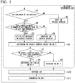
- Fig. 3 is a flowchart of example 1 of the transmission method according to the first embodiment.
- Fig. 4 is a flowchart of example 2 of the transmission method according to the first embodiment.
- Example 1 of the transmission method according to the first embodiment will now be described with reference to Fig. 3 .
- Acknowledgment information f_(N, m) is input from the reception unit 13 to the CW update determination unit 14.
- the acknowledgement information f_(N, m) is information of all ACK and NACK signals included in a feedback signal F_(N, m) that the reception unit 13 has received from destinations to which the transmission unit 12 has performed transmission #N.
- m is an integer from 1 to M.
- M is the number of subframes transmitted by the transmission unit 12 at the transmission #N.
- hybrid automatic repeat request (HARQ) ACKs and NACKs included in physical uplink control channel (PUCCH) resources (on a licensed band or an unlicensed band) of a UL subframe #m+x correspond to ACK and NACK signals included in the feedback signal F_(N, m).
- PUCCH physical uplink control channel
- the value of x in the above "subframe #m+x" is 4 in LTE, but is being studied in LAA.
- the CW update determination unit 14 In response to the input of the acknowledgement information f_(N, m) from the reception unit 13, the CW update determination unit 14 outputs, to the transmission unit 12, a maximum CW value to be applied to LBT before transmission of the transmission #N+1.
- Step S1 On the basis of the acknowledgement information f_(N, m), the CW update determination unit 14 determines whether or not an ACK signal or a NACK signal for the transmission #N has been received. If the result of the determination is that an ACK signal or a NACK signal for the transmission #N has been received, the CW update determination unit 14 proceeds to step S2 and otherwise proceeds to step S5.
- Step S2 The CW update determination unit 14 determines whether or not the total number of received NACK signals for the transmission #N or the number of ACK signal timeouts for the transmission #N is equal to or less than a threshold value. If the result of the determination is that the total number of received NACK signals or the number of ACK signal timeouts is equal to or less than the threshold value, the CW update determination unit 14 proceeds to step S3 and otherwise proceeds to step S4.
- the CW update determination unit 14 may determine whether or not the total number of received NACK signals for the transmission #N or the number of ACK signal timeouts for the transmission #N is equal to or greater than a threshold value, and may proceed to step S4 if the result of the determination is that it is equal to or greater than the threshold value and otherwise proceed to step S3.
- Step S3 The CW update counter 15 initializes or decreases the CW update counter value.
- Step S4 The CW update counter 15 increases the CW update counter value.
- Step S5 The CW update counter 15 keeps the CW update counter value unchanged.
- Step S6 The CW update determination unit 14 acquires the CW update counter value for the transmission #N+1 from the CW update counter 15.
- Step S7 The CW update determination unit 14 determines whether or not the acquired CW update counter value is equal to or less than a threshold value. If the result of the determination is that the acquired CW update counter value is equal to or less than the threshold value, the CW update determination unit 14 proceeds to step S8 and otherwise proceeds to step S9.
- Step S8 The CW update determination unit 14 initializes the maximum CW value or decreases the maximum CW value by X, such that the resulting value is less than the current value by X.
- the value of X may be arbitrarily set.
- Step S9 The CW update determination unit 14 increases the maximum CW value by Y, such that the resulting value is greater than the current value by Y.
- the value of Y may be arbitrarily set.
- Step S10 The CW update determination unit 14 outputs the resulting maximum CW value of step S8 or step S9 to the transmission unit 12 for the transmission #N+1. On the basis of the maximum CW value, the transmission unit 12 determines a backoff time to be applied to LBT before transmission to destinations to which transmission has been scheduled to be performed at the transmission #N+1.
- step S3 the CW update counter 15 initializes the CW update counter value in any case.
- the CW update counter 15 initializes the CW update counter value. In the case of example 2 with this initialization condition, if at least one NACK signal is included in the acknowledgement information f_(N, m), the CW update counter 15 may keep the CW update counter value unchanged, regardless of the result of the above step S2. This can achieve an improved interference avoidance rate.
- the example 2 of the transmission method according to the first embodiment will now be described with reference to Fig. 4 .
- portions corresponding to steps of Fig. 3 are denoted by the same reference signs as those of Fig. 3 and descriptions thereof are omitted.
- the example 2 of the transmission method according to the first embodiment shown in Fig. 4 differs from the example 1 of the transmission method according to the first embodiment shown in Fig. 3 only in terms of a portion corresponding to step S2 of the example 1 and the other steps are similar.
- Acknowledgment information f_(N, m) is input from the reception unit 13 to the CW update determination unit 14.
- the CW update determination unit 14 In response to the input of the acknowledgement information f_(N, m) from the reception unit 13, the CW update determination unit 14 outputs a maximum CW value to be applied to LBT before transmission of the transmission #N+1 to the transmission unit 12.
- step S21 the CW update determination unit 14 proceeds to step S21 if the result of step S1 is that an ACK signal or a NACK signal for the transmission #N has been received and proceeds to step S5 if both an ACK signal and a NACK signal for the transmission #N have not been received.
- Step S21 The CW update determination unit 14 determines whether or not an index is equal to or less than a threshold value. This index is "(the total number of received NACK signals or the number of ACK signal timeouts)/(the total number of received ACK signals + (the total number of received NACK signals or the number of ACK signal timeouts))." If the result of the determination is that the index is equal to or less than the threshold value, the CW update determination unit 14 proceeds to step S3 and otherwise proceeds to step S4.
- the CW update determination unit 14 may determine whether or not the index "(the total number of received NACK signals or the number of ACK signal timeouts)/(the total number of received ACK signals + (the total number of received NACK signals or the number of ACK signal timeouts))" is equal to or greater than a threshold value, and may proceed to step S4 if the result of the determination is that the index is equal to or greater than the threshold value and otherwise proceed to step S3.
- the total number of ACK signals and NACK signals returned changes according to the number of destinations allocated to the DL subframe #m of the transmission #N.
- step S3 the CW update counter 15 initializes the CW update counter value in any case.
- the CW update counter 15 initializes the CW update counter value. In the case of example 2 with this initialization condition, if the index "(the total number of received NACK signals or the number of ACK signal timeouts)/(the total number of received ACK signals + (the total number of received NACK signals or the number of ACK signal timeouts))" is not 0, the CW update counter 15 may keep the CW update counter value unchanged, regardless of the result of the above step S21. This can achieve an improved interference avoidance rate.
- Fig. 5 is a schematic configuration diagram of a base station 1 according to a second embodiment.
- the base station 1 according to the second embodiment shown in Fig. 5 includes a reception failure counter 16 in addition to the components of the CW update determination unit 14 of the base station 1 according to the first embodiment shown in Fig. 2 .
- a reception failure counter 16 in addition to the components of the CW update determination unit 14 of the base station 1 according to the first embodiment shown in Fig. 2 .
- the reception failure counter 16 holds a reception failure counter value for each terminal that has established a connection with the base station 1.
- a terminal that has established a connection with the base station 1 is a destination to which the transmission unit 12 transmits data.
- the reception failure counter 16 updates the reception failure counter value for each destination on the basis of an ACK signal and a NACK signal from the destination for data transmitted by the transmission unit 12.
- the CW update counter 15 updates the CW update counter value on the basis of the reception failure counter value.
- Fig. 6 is a flowchart of example 1 of a transmission method according to the second embodiment.
- Fig. 7 is a flowchart of example 2 of the transmission method according to the second embodiment.
- the example 1 of the transmission method according to the second embodiment will now be described with reference to Fig. 6 .
- portions corresponding to steps of Fig. 3 are denoted by the same reference signs as those of Fig. 3 and descriptions thereof are omitted.
- the example 1 of the transmission method according to the second embodiment shown in Fig. 6 differs from the example 1 of the transmission method in the first embodiment shown in Fig. 3 in terms of the method of determining the CW update counter value.
- Acknowledgment information f_(N, m) is input from the reception unit 13 to the CW update determination unit 14.
- the CW update determination unit 14 In response to the input of the acknowledgement information f_(N, m) from the reception unit 13, the CW update determination unit 14 outputs a maximum CW value to be applied to LBT before transmission of the transmission #N+1 to the transmission unit 12.
- Step S30 The transmission unit 12 performs the transmission #N and the reception unit 13 inputs the acknowledgement information f_(N, m) to the CW update determination unit 14.
- the acknowledgement information f_(N, m) includes information on an ACK signal and a NACK signal for each destination.
- steps S31 to S35 are performed for each destination of the transmission #N.
- destination 1 one of the destinations of the transmission #N is referred to as destination 1 and the following description will be given with reference to the destination 1 as an example.
- Step S31 On the basis of the acknowledgement information f_(N, m), the CW update determination unit 14 determines whether or not an ACK signal or NACK signal for the transmission #N has been received from the destination 1. If the result of the determination is that an ACK signal or a NACK signal for the transmission #N has been received from the destination 1, the CW update determination unit 14 proceeds to step S32 and otherwise proceeds to step S35.
- Step S32 The CW update determination unit 14 determines whether or not an ACK signal timeout of the destination 1 has occurred or whether or not a NACK signal has been received from the destination 1. If the result of the determination is that an ACK signal timeout of the destination 1 has occurred or a NACK signal has been received from the destination 1, the CW update determination unit 14 proceeds to step S33 and otherwise proceeds to step S34.
- Step S33 The reception failure counter 16 increases a reception failure counter value of the destination 1.
- the reception failure counter 16 initializes the reception failure counter value of the destination 1.
- Step S35 The reception failure counter 16 keeps the reception failure counter value of the destination 1 unchanged.
- step S36 the CW update determination unit 14 proceeds to step S36.
- Step S36 The CW update determination unit 14 acquires all reception failure counter values from the reception failure counter 16.
- the CW update determination unit 14 selects a maximum value from the acquired reception failure counter values.
- the CW update counter 15 sets the selected maximum reception failure counter value as the CW update counter value.
- the CW update counter value for the transmission #N+1 is determined.
- steps S7 to S10 are performed. Steps S7 to S10 are similar to those of the example 1 of the transmission method according to the first embodiment described above with reference to Fig. 3 .
- the reception failure counter value of the terminal may be initialized.
- the example 2 of the transmission method according to the second embodiment will now be described with reference to Fig. 7 .
- Fig. 7 portions corresponding to steps of Fig. 6 are denoted by the same reference signs as those of Fig. 6 and descriptions thereof are omitted.
- the example 2 of the transmission method according to the second embodiment shown in Fig. 7 differs from the example 1 of the transmission method according to the second embodiment shown in Fig. 6 only in terms of portions (steps S40 to S43 of Fig. 7 ) corresponding to step S36 of the example 1 and the other steps are similar.
- Acknowledgment information f_(N, m) is input from the reception unit 13 to the CW update determination unit 14.
- the CW update determination unit 14 In response to the input of the acknowledgement information f_(N, m) from the reception unit 13, the CW update determination unit 14 outputs a maximum CW value to be applied to LBT before transmission of the transmission #N+1 to the transmission unit 12.
- Step S30 to S35 are similar to those of the example 1 of the transmission method according to the second embodiment described above with reference to Fig. 6 .
- Step S40 Each reception failure counter value of the reception failure counter 16 is determined.
- the CW update determination unit 14 acquires all reception failure counter values from the reception failure counter 16. The CW update determination unit 14 determines whether or not a number of reception failure counter values, which are equal to or greater than a threshold value ⁇ 1 among the acquired reception failure counter values, is equal to or greater than a threshold value ⁇ 2. If the result of the determination is that the number of reception failure counter values being equal to or greater than the threshold value ⁇ 1 is equal to or greater than the threshold value ⁇ 2, the CW update determination unit 14 proceeds to step S42 and otherwise proceeds to step S43.
- Step S42 The CW update counter 15 increases the CW update counter value.
- Step S43 The CW update counter 15 initializes or decreases the CW update counter value.
- steps S7 to S10 are performed. Steps S7 to S10 are similar to those of the example 1 of the transmission method according to the first embodiment described above with reference to Fig. 3 .
- the example 2 of the transmission method according to the second embodiment it is possible to achieve both packet collision avoidance and an improvement in the utilization efficiency of time resources by enlarging the CW only when packet collisions have occurred at a number of destinations equal to a greater than a predetermined number.
- the CW is not enlarged in a situation where packet collisions have occurred only at a very small number of destinations, whereby it is possible to prevent LBT from being performed with the enlarged CW even before transmission to the other destinations and to prevent a reduction in the utilization efficiency of time resources.
- the base station 1 may further include an acknowledgement information history recording unit that records a history of acknowledgement information and the CW update counter 15 may update the CW update counter value on the basis of the history of acknowledgement information. Examples 1-1 and 1-2 of the method of updating the CW update counter value will be described below.
- the CW update counter 15 increases the CW update counter value.
- the CW update counter 15 may use a predetermined unit time (P ms) or a predetermined number of times (P times) of transmission by the transmission unit 12 as the predetermined condition P.
- the CW update counter 15 increases the CW update counter value.
- the predetermined condition P may be similar to that of the example 1-1 of the method of updating the CW update counter value.
- the base station 1 may further include a reception failure counter value history recording unit that records a reception failure counter value history and the CW update counter 15 may update the CW update counter value on the basis of the reception failure counter value history. Examples 2-1 and 2-2 of the method of updating the CW update counter value will be described below.
- the CW update counter 15 sets a maximum value among all reception failure counter values within a predetermined condition P in the past as the CW update counter value.
- the predetermined condition P may be similar to that of the example 1-1 of the method of updating the CW update counter value.
- the CW update counter 15 increases the CW update counter value when a number of reception failure counter values which are equal to or greater than the threshold value ⁇ 1 within the predetermined condition P in the past among all reception failure counter values is equal to or greater than the threshold value ⁇ 2.
- the predetermined condition P may be similar to that of the example 1-1 of the method of updating the CW update counter value.
- the CW update counter 15 may provide a forgetting factor for each counter value within the predetermined condition P in the past to weight the counter value such that a most recent history is prioritized.
- FIG. 8 is an explanatory diagram of a comparative example in which a backoff time to be applied to LBT before transmission to a plurality of scheduled transmission destinations is determined without taking into consideration the plurality of scheduled transmission destinations.
- Letters (A to H) in subframes transmitted from the base station indicate destination stations of data included in the sub frames.
- Letters (A to C) in subframes of feedback signals transmitted from terminals indicate source stations of the feedback signals (ACK and NACK signals) included in the subframes.
- the base station After terminating the transmission #N, the base station allocates destination stations of transmission #N+1. After terminating the transmission #N+1, the base station allocates destination stations of transmission #N+2.
- the base station determines a backoff time to be applied to LBT before transmission of the transmission #N+2 on the basis of ACK and NACK signals for the transmission #N.
- the plurality of scheduled transmission destinations of the transmission #N+2 are different from the plurality of scheduled transmission destinations of the transmission #N. Therefore, the backoff time determined on the basis of ACK and NACK signals for the transmission #N may be inappropriate for the plurality of scheduled transmission destinations of the transmission #N+2.
- packet collisions may not occur around a plurality of scheduled transmission destinations in transmission of the transmission #N+2 although the CW has been enlarged on the basis of ACK and NACK signals for the transmission #N, and thus the utilization efficiency of time resources may be reduced in proportion to an increase in the backoff time.
- packet collisions may be likely to occur around a plurality of scheduled transmission destinations in transmission of the transmission #N+2 although the CW has been reduced on the basis of ACK and NACK signals for the transmission #N, and thus packet collisions may become more likely to occur due to a decreased backo ff time.
- a back-off time to be applied to LBT before transmission to a plurality of scheduled transmission destinations is determined taking into consideration the plurality of scheduled transmission destinations, thereby achieving determination of an appropriate backoff time for the plurality of scheduled transmission destinations.
- Fig. 9 is a schematic configuration diagram of a base station 1 according to the third embodiment.
- the base station 1 includes a scheduler 11, a transmission unit 12, a reception unit 13, a CW update determination unit 14, and a reception failure flag management unit 21.
- the CW update determination unit 14 includes a CW update counter 15.
- the scheduler 11, the transmission unit 12, and the reception unit 13 are similar to those of the first embodiment described above.
- the reception failure flag management unit 21 holds a reception failure flag for each terminal that has established a connection with the base station 1.
- the reception failure flag management unit 21 updates the reception failure flag for each destination on the basis of an ACK signal and a NACK signal from each destination for data transmitted by the transmission unit 12.
- the initial value of the reception failure flag is off.
- the CW update counter 15 holds a CW update counter value.
- the CW update counter 15 updates the CW update counter value on the basis of the reception failure flag of the scheduled transmission destination.
- the CW update counter 15 updates the CW update counter value on the basis of reception failure flags of the plurality of scheduled transmission destinations.
- the CW update determination unit 14 determines a maximum CW value to be applied to LBT which is to be performed before transmission to the transmission destinations.
- the maximum CW value corresponds to a settable range of the backoff time.
- the settable range of the backoff time corresponds to at least part of a settable range of the common waiting time for the plurality of scheduled transmission destinations.
- Fig. 10 is a flowchart of example 1 of the transmission method according to the third embodiment.
- Fig. 11 is a flowchart of example 2 of the transmission method according to the third embodiment.
- the example 1 of the transmission method according to the third embodiment will now be described with reference to Fig. 10 .
- Acknowledgment information f_(N, m) is input from the reception unit 13 to the reception failure flag management unit 21.
- the acknowledgement information f_(N, m) is similar to that of each of the embodiments described above.
- Step S50 The transmission unit 12 performs transmission #N and the reception unit 13 inputs the acknowledgement information f_(N, m) to the reception failure flag management unit 21.
- the acknowledgement information f_(N, m) includes information on an ACK signal and a NACK signal for each destination.
- steps S51 to S55 are performed for each destination of the transmission #N.
- destination 1 one of the destinations of the transmission #N is referred to as destination 1 and the following description will be given with reference to the destination 1 as an example.
- Step S51 On the basis of the acknowledgement information f_(N, m), the reception failure flag management unit 21 determines whether or not an ACK signal or a NACK signal for the transmission #N has been received from the destination 1. If the result of the determination is that an ACK signal or a NACK signal for the transmission #N has been received from the destination 1, the reception failure flag management unit 21 proceeds to step S52 and otherwise proceeds to step S55.
- Step S52 The reception failure flag management unit 21 determines whether or not an ACK signal timeout of the destination 1 has occurred or whether or not a NACK signal has been received from the destination 1. If the result of the determination is that an ACK signal timeout of the destination 1 has occurred or a NACK signal has been received from the destination 1, the reception failure flag management unit 21 proceeds to step S53 and otherwise proceeds to step S54.
- Step S53 The reception failure flag management unit 21 turns on the reception failure flag of the destination 1.
- Step S54 The reception failure flag management unit 21 turns off the reception failure flag of the destination 1.
- Step S55 The reception failure flag management unit 21 keeps the reception failure flag of the destination 1 unchanged.
- step S56 the CW update determination unit 14 proceeds to step S56.
- the CW update determination unit 14 acquires the (ON or OFF) value of the reception failure flag of the scheduled transmission destination from the reception failure flag management unit 21. When there are a plurality of scheduled transmission destinations, the CW update determination unit 14 acquires the (ON or OFF) values of the reception failure flags of the plurality of scheduled transmission destinations. A notification of the scheduled transmission destinations is provided from the transmission unit 12 to the CW update determination unit 14. The transmission unit 12 notifies the CW update determination unit 14 of a next scheduled transmission destination. The CW update determination unit 14 aggregates ON values among the (ON or OFF) values of reception failure flags of next scheduled transmission destinations, of which the transmission unit 12 has notified.
- Step S57 The CW update determination unit 14 determines whether or not the aggregate number of ON values is equal to or greater than a threshold value. If the result of the determination is that the aggregate number of ON values is equal to or greater than the threshold value, the CW update determination unit 14 proceeds to step S58 and otherwise proceeds to step S59.
- Step S58 The CW update counter 15 increases the CW update counter value.
- Step S59 The CW update counter 15 initializes or decreases the CW update counter value.
- Step S60 The CW update determination unit 14 determines whether or not the CW update counter value is equal to or less than a threshold value. If the result of the determination is that the CW update counter value is equal to or less than the threshold value, the CW update determination unit 14 proceeds to step S61 and otherwise proceeds to step S62.
- Step S61 The CW update determination unit 14 initializes the maximum CW value or decreases the maximum CW value by Y', such that the resulting value is less than the current value by Y'.
- the value of Y' may be arbitrarily set.
- Step S62 The CW update determination unit 14 keeps the maximum CW value unchanged or increases the maximum CW value by X', such that the resulting value is greater than the current value by X'.
- the value of X' may be arbitrarily set.
- Step S63 The CW update determination unit 14 outputs the resulting maximum CW value of step S61 or step S62 to the transmission unit 12. On the basis of the maximum CW value, the transmission unit 12 determines a backoff time to be applied to LBT before transmission to the next scheduled transmission destination.
- the example 2 of the transmission method according to the third embodiment will now be described with reference to Fig. 11 .
- Fig. 11 portions corresponding to steps of Fig. 10 are denoted by the same reference signs as those of Fig. 10 and descriptions thereof are omitted.
- the example 2 of the transmission method according to the third embodiment shown in Fig. 11 differs from the example 1 of the transmission method according to the third embodiment shown in Fig. 10 only in terms of a portion corresponding to step S52 of the example 1 and the other steps are similar.
- the reception failure flag management unit 21 further includes an acknowledgement information history recording unit that records a history of acknowledgement information.
- Step S50 The transmission unit 12 performs transmission #N and the reception unit 13 inputs acknowledgement information f_(N, m) to the reception failure flag management unit 21.
- the acknowledgement information f_(N, m) includes information on an ACK signal and a NACK signal for each destination.
- steps S51, S71, and S53 to S55 are performed for each destination of the transmission #N.
- destination 1 one of the destinations of the transmission #N is referred to as destination 1 and the following description will be given with reference to the destination 1 as an example.
- Step S51 On the basis of the acknowledgement information f_(N, m), the reception failure flag management unit 21 determines whether or not an ACK signal or a NACK signal for the transmission #N has been received from the destination 1. If the result of the determination is that an ACK signal or a NACK signal for the transmission #N has been received from the destination 1, the reception failure flag management unit 21 proceeds to step S71 and otherwise proceeds to step S55.
- Step S71 On the basis of the history of acknowledgement information, the reception failure flag management unit 21 determines whether or not the total number of received NACK signals within a predetermined condition P in the past for the destination 1 is equal to or greater than a threshold value. If the result of the determination is that the total number of received NACK signals is equal to or greater than the threshold value, the reception failure flag management unit 21 proceeds to step S53 and otherwise proceeds to step S54.
- the reception failure flag management unit 21 may use a predetermined unit time (P ms) or a predetermined number of times (P times) of transmission by the transmission unit 12 as the predetermined condition P.
- Steps S53 to S55 are similar to those of the example 1 of the transmission method according to the third embodiment described above with reference to Fig. 10 .
- the CW update determination unit 14 proceeds to step S56.
- Steps S56 to S63 are similar to those of the example 1 of the transmission method according to the third embodiment described above with reference to Fig. 10 .
- the example 2 of the transmission method according to the third embodiment by using the record of the past, it is particularly possible to enlarge the CW only when performing transmission to a destination where packet collisions are likely to occur and thus to achieve an improvement in the utilization efficiency of time resources.
- the third embodiment taking into consideration a plurality of scheduled transmission destinations, it is possible to determine a back-off time to be applied to LBT before transmission to the plurality of scheduled transmission destinations. Thereby, it is possible to obtain an advantageous effect that it is possible to determine an appropriate backoff time for a plurality of scheduled transmission destinations.
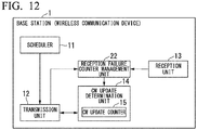
- Fig. 12 is a schematic configuration diagram of a base station 1 according to the fourth embodiment.
- the base station 1 includes a scheduler 11, a transmission unit 12, a reception unit 13, a CW update determination unit 14, and a reception failure counter management unit 22.
- the CW update determination unit 14 includes a CW update counter 15.
- the scheduler 11, the transmission unit 12, and the reception unit 13 are similar to those of the first embodiment described above.
- the reception failure counter management unit 22 holds a reception failure counter value for each terminal that has established a connection with the base station 1.
- the initial value of the reception failure counter value is 0.
- a terminal that has established a connection with the base station 1 is a destination to which the transmission unit 12 transmits data.
- the reception failure counter management unit 22 updates the reception failure counter value for each destination on the basis of an ACK signal and a NACK signal from each destination for data transmitted by the transmission unit 12.
- the CW update counter 15 holds the CW update counter value.
- the CW update counter 15 updates the CW update counter value on the basis of the reception failure counter value of the scheduled transmission destination.
- the CW update counter 15 updates the CW update counter value on the basis of the reception failure counter values of the plurality of scheduled transmission destinations.
- the CW update determination unit 14 determines a maximum CW value to be applied to LBT before transmission to the scheduled transmission destinations.
- the maximum CW value corresponds to a settable range of the backoff time.
- the settable range of the backoff time corresponds to at least part of a settable range of the common waiting time for the plurality of scheduled transmission destinations.
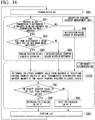
- Fig. 13 is a flowchart of example 1 of the transmission method according to the fourth embodiment.
- Fig. 14 is a flowchart of example 2 of the transmission method according to the fourth embodiment.
- Step S80 The transmission unit 12 performs transmission #N and the reception unit 13 inputs acknowledgement information f_(N, m) to the CW update determination unit 14.
- the acknowledgement information f_(N, m) includes information on an ACK signal and a NACK signal for each destination.
- steps S81 to S85 are performed for each destination of the transmission #N.
- destination 1 one of the destinations of the transmission #N is referred to as destination 1 and the following description will be given with reference to the destination 1 as an example.
- Step S81 On the basis of the acknowledgement information f_(N, m), the reception failure counter management unit 22 determines whether or not an ACK signal or NACK signal for the transmission #N has been received from the destination 1. If the result of the determination is that an ACK signal or a NACK signal for the transmission #N has been received from the destination 1, the reception failure counter management unit 22 proceeds to step S82 and otherwise proceeds to step S85.
- Step S82 The reception failure counter management unit 22 determines whether or not an ACK signal timeout of the destination 1 has occurred or whether or not a NACK signal has been received from the destination 1. If the result of the determination is that an ACK signal timeout of the destination 1 has occurred or a NACK signal has been received from the destination 1, the reception failure counter management unit 22 proceeds to step S83 and otherwise proceeds to step S84.
- Step S83 The reception failure counter management unit 22 increases the reception failure counter value of the destination 1.
- Step S84 The reception failure counter management unit 22 initializes or decreases the reception failure counter value of the destination 1.
- Step S85 The reception failure counter management unit 22 keeps the reception failure counter value of the destination 1 unchanged.
- step S86 the CW update determination unit 14 proceeds to step S86.
- the CW update determination unit 14 acquires the reception failure counter value of the scheduled transmission destination from the reception failure counter management unit 22. When there are a plurality of scheduled transmission destinations, the CW update determination unit 14 acquires reception failure counter values of the plurality of scheduled transmission destinations. A notification of the scheduled transmission destinations is provided from the transmission unit 12 to the CW update determination unit 14. The transmission unit 12 notifies the CW update determination unit 14 of a next scheduled transmission destination. The CW update determination unit 14 selects a maximum value from the reception failure counter values of next scheduled transmission destinations, of which the transmission unit 12 has notified. The CW update counter 15 sets the selected maximum reception failure counter value as the CW update counter value.
- the CW update determination unit 14 may calculate an average of the reception failure counter values of the next scheduled transmission destinations, of which the transmission unit 12 has notified, and set the average as the CW update counter value.
- Step S87 The CW update determination unit 14 determines whether or not the CW update counter value is equal to or less than a threshold value. If the result of the determination is that the CW update counter value is equal to or less than the threshold value, the CW update determination unit 14 proceeds to step S88 and otherwise proceeds to step S89.
- Step S88 The CW update determination unit 14 initializes the maximum CW value or decreases the maximum CW value by Y', such that the resulting value is less than the current value by Y'.
- the value of Y' may be arbitrarily set.
- Step S89 The CW update determination unit 14 keeps the maximum CW value unchanged or increases the maximum CW value by X', such that the resulting value is greater than the current value by X'.
- the value of X' may be arbitrarily set.
- Step S90 The CW update determination unit 14 outputs the resulting maximum CW value of step S88 or step S89 to the transmission unit 12. On the basis of the maximum CW value, the transmission unit 12 determines a backoff time to be applied to LBT before transmission to the next scheduled transmission destinations.
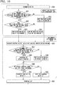
- the example 2 of the transmission method according to the fourth embodiment will now be described with reference to Fig. 14 .
- Fig. 14 portions corresponding to steps of Fig. 13 are denoted by the same reference signs as those of Fig. 13 and descriptions thereof are omitted.
- the example 2 of the transmission method according to the fourth embodiment shown in Fig. 14 differs from the example 1 of the transmission method according to the fourth embodiment shown in Fig. 13 only in terms of a portion (step S100 in Fig. 14 ) corresponding to step S86 of the example 1 and the other steps are similar.
- Step S80 to S85 are similar to those of the example 1 of the transmission method according to the fourth embodiment described above with reference to Fig. 13 .
- the CW update determination unit 14 selects a destination, to which the greatest amount of wireless resources have been allocated as a determination reference, from scheduled transmission destinations.
- the transmission unit 12 notifies the CW update determination unit 14 of the scheduled transmission destinations and the amounts of allocated wireless resources allocated thereto as determination references.
- the wireless resources as a determination reference may be time resources or frequency resources or may be both time and frequency resources.
- the CW update determination unit 14 may select a destination with the greatest amount of either time resources or frequency resources allocated thereto or may select a destination with the greatest amount of both time resources and frequency resources allocated thereto.
- the CW update determination unit 14 may determine the amount of allocated time and frequency resources in a comprehensive manner and select a destination to which the greatest comprehensive amount of resources have been allocated.
- the CW update determination unit 14 acquires from the reception failure counter management unit 22 a reception failure counter value of the destination which is selected as a destination, to which the greatest amount of wireless resources have been allocated as a determination reference, from the scheduled transmission destinations. When there are a plurality of selected destinations, the CW update determination unit 14 acquires reception failure counter values of the plurality of selected destinations.
- the CW update determination unit 14 selects a maximum value from the reception failure counter values acquired from the reception failure counter management unit 22.
- the CW update counter 15 sets the selected maximum reception failure counter value as the CW update counter value.
- Steps S87 to S90 are similar to those of the example 1 of the transmission method according to the fourth embodiment described above with reference to Fig. 13 .
- the example 2 of the transmission method according to the fourth embodiment it is possible to contribute to controlling the probability of packet collision in communication of a destination, which most greatly consumes wireless resources as a determination reference, to an appropriate value.
- the CW update determination unit 14 may use a CW update counter value, which is based on acknowledgement information of transmission #N-1 immediately previous to the transmission #N, for the transmission #N+1.
- the method of updating the maximum CW value may be similar to that of the Wi-Fi LBT technology shown in Fig. 15 .
- the CW update determination unit 14 may use the CW update counter value according to the present embodiment instead of the number of retransmissions n used in the Wi-Fi LBT technology.
- the CW update determination unit 14 may calculate the maximum CW value, similar to the Wi-Fi LBT technology. To calculate this maximum CW value, a CW update counter value determined in steps prior to step S7 shown in Figs. 3 , 4 , 6 and 7 is used as the number of retransmissions n.
- the CW update determination unit 14 may calculate the maximum CW value, similar to the Wi-Fi LBT technology. To calculate this maximum CW value, a CW update counter value determined in steps prior to step S60 shown in Figs. 10 and 11 is used as the number of retransmissions n. Further, instead of steps S87 to S89 shown in Figs. 13 and 14 , the CW update determination unit 14 may calculate the maximum CW value, similar to the Wi-Fi LBT technology. To calculate this maximum CW value, a CW update counter value determined in steps prior to step S87 shown in Figs. 13 and 14 is used as the number of retransmissions n.
- the CW update determination unit 14 may use a plurality of threshold values as a method of updating the CW update counter value in each of the above-described embodiments. For example, in each of step S2 in Fig. 3 , step S21 in Fig. 4 , and step S57 in Figs. 10 and 11 , the CW update determination unit 14 may increase the CW update counter if a corresponding index (which is a value to be compared with a threshold value) is equal to or greater than threshold value A, initialize or decrease the CW update counter if the index is equal to or less than threshold value B, and keep the CW update counter if neither.
- a corresponding index which is a value to be compared with a threshold value
- the present invention may be applied to other wireless communication systems such as a wireless LAN.
- the present invention may be applied to wireless LAN access point devices.
- the present invention may be applied to other wireless communication devices such as terminals that perform terminal-to-terminal communication.
- a computer program for realizing the functions of the base station 1 (wireless communication device) described above may be recorded on a computer readable recording medium, such that a computer system reads and executes the program recorded on the recording medium.
- the "computer system” referred to here may be that which includes an OS or hardware such as peripheral devices.
- “computer readable recording medium” refers to a storage device such as a flexible disk, a magneto-optical disk, a ROM, a nonvolatile writable memory such as a flash memory, a portable medium such as a digital versatile disk (DVD), or a hard disk provided in a computer system.
- the present invention can also be applied to applications where it is necessary to appropriately determine a waiting time when transmission to a plurality of destinations is performed.
Landscapes
- Engineering & Computer Science (AREA)
- Computer Networks & Wireless Communication (AREA)
- Signal Processing (AREA)
- Mobile Radio Communication Systems (AREA)
Abstract
Description
- The present invention relates to a wireless communication device, a transmission method and a computer program.
- Priority is claimed on Japanese Patent Application No.
2015-160212, filed August 14, 2015 - A listen before talk (LBT) technology is known in the related art. In the LBT technology, when a plurality of communication carriers or wireless communication systems share a frequency band, a wireless communication device senses the usage status of the frequency band before performing transmission and determines whether or not it is possible to perform transmission on the basis of the carrier-sense result in order not to cause radio interference with other wireless communication devices that share the frequency band. In an LBT technology for a wireless LAN called Wi-Fi (registered trademark) as one of the LBT technologies, carrier-sense is performed during a fixed waiting time plus a randomly determined waiting time to stochastically avoid collisions (for example, see Non-Patent Literature 1). The randomly determined waiting time is called a backoff time (Backoff).
-
Fig. 15 is an explanatory diagram of a related-art Wi-Fi LBT technology. As shown inFig. 15 , before performing transmission, a wireless LAN device performs carrier-sense during a time which is the sum of a fixed waiting time (a distributed inter-frame space (DIFS)) and a randomly determined waiting time (a backoff time). The backoff time is determined according to a backoff value randomly selected from a range of 0 to a contention window (CW) with a uniform probability. When the wireless LAN device has not received an acknowledgement (ACK) signal within a certain time for data that the wireless LAN device has transmitted at transmission #N (i.e., when a reception failure has occurred), the CW is enlarged to increase a probability that the backoff time becomes greater (where Backoff = Random([0, CWmin*2(n-1) - 1]); n = 1,2, ...) in order to lower a probability that packets collide at transmission #N+1. The CW is increased twofold each time. An initial value of the CW is 15 and a maximum value of the CW is 1023. When an ACK signal has been received for data of the transmission #N+1, the enlarged CW returns to the initial value at transmission #N+2 (i.e., Backoff = Random([0, CWmin - 1]); n = 0). In the case of Wi-Fi, whether reception of the previous transmission #N has been successful or has failed must be determined before starting LBT for the transmission #N+1. The wireless LAN device transmits data to a single destination, performs management on whether or not an ACK signal has been received from the single destination, and determines a backoff value for a next transmission according to whether or not an ACK signal has been received from the single destination. The maximum time length of data transmission is set as a maximum transmit duration (MTD). In Japan, the maximum time length is 4 ms. - Licensed-assisted access (LAA) is being studied in the standardization of specifications for a next generation mobile communication system in the third generation partnership project (3GPP) (for example, see Non-Patent Literature 2). LAA is a technology for performing long term evolution (LTE) communication while sharing a frequency band with another wireless communication system. A wireless station (a base station (eNB) or a terminal (UE)), to which LAA is applied, has an LBT function to avoid radio interference with another wireless communication system such as a Wi-Fi communication system which uses the same frequency band.
- The LBT function of LAA performs the following processes.
- Comparing the power level of a frequency band in use, which has been acquired by carrier-sense, with a threshold value and determining that the status is busy if the power level of the frequency band in use is greater than the threshold value and the status is idle if the power level is equal to or less than the threshold value.
- Performing transmission if the status is kept idle for a set waiting time which is the sum of a fixed waiting time and a randomly determined waiting time (a backoff time (Backoff)).
- [Patent Literature 1]
Japanese Unexamined Patent Application, First Publication No.2014-165512 -
- [Non-Patent Literature 1]
IEEE Std 802.11ac(TM)-2013 - [Non-Patent Literature 2]
3 GPP, "TR 36.889" -
Fig. 16 is an explanatory view ofproblems first subframe # 1 includes data for transmission to destinations #i and #j. Thesecond subframe # 2 includes data for transmission to destinations #i and #k. The thirdsub frame # 3 includes data for transmission to a destination #j. Thefourth subframe # 4 includes data for transmission to the destination #i. Subframes are also used to transmit a feedback signal for the transmission #N of the base station. The subframes in the feedback signal correspond respectively to the subframes of data transmission from the base station. For example, the feedback signal includes an ACK signal from the destination #i to the base station and a negative acknowledgement (NACK) signal from the destination #j to the base station. The feedback signal for the transmission #N includes six responds (ACK and NACK signals) and the CW is updated on the basis of the feedback signal. A backoff time included in a waiting time before the transmission N+2 is performed is determined on the basis of the updated CW. - (Problem 1) At a single data transmission, the LAA base station can transmit data to a plurality of destination terminals. When data is simultaneously transmitted to a plurality of destinations, the LAA base station performs management on whether or not an ACK signal and an NACK signal have been received from each destination. Here, in LAA, whether the previous transmission #N has been successful or has failed is not always all determined before LBT for the transmission #N+1 starts. Before LBT for the transmission #N+1 starts, an ACK signal and an NACK signal may fail to be received from at least one of the plurality of destinations to which data has been transmitted at the transmission #N. Therefore, it is not possible to determine a backoff value for LBT of LAA using the LBT method such as that of the related-art Wi-Fi LBT technology in which the wireless LAN device transmits data to a single destination, performs management on whether or not an ACK signal has been received from the single destination, and determines a backoff value for a next transmission according to whether or not an ACK signal has been received from the single destination.
- (Problem 2) In LAA, ACK signals or NACK signals are returned from a plurality of destinations to which data has been transmitted at the transmission #N. Therefore, using the LBT method such as that of the related-art Wi-Fi LBT technology in which the wireless LAN device transmits data to a single destination, performs management on whether or not an ACK signal has been received from the single destination, and determines a backoff value for a next transmission according to whether or not an ACK signal has been received from the single destination, it is not possible to determine a backoff value for LBT of LAA in the case in which ACK signals or NACK signals are returned from a plurality of destinations in LAA.
- The present invention has been made in view of such circumstances and it is an object of the present invention to provide a wireless communication device, a transmission method, and a computer program which can appropriately determine a waiting time when transmission to a plurality of destinations is performed.
-
- (1) An aspect of the present invention is a wireless communication device including a transmission unit configured to transmit a signal to a plurality of destinations after waiting for a common waiting time set for transmission to the plurality of destinations, a counter configured to update a counter value on the basis of acknowledgement information from each destination for the signal transmitted by the transmission unit, and an update determination unit configured to determine a settable range of the common waiting time which is to be set for transmission to a plurality of scheduled transmission destinations according to the counter value, wherein the transmission unit is configured to determine the common waiting time for transmission to the plurality of scheduled transmission destinations on the basis of the settable range determined by the update determination unit.
- (2) An aspect of the present invention is the wireless communication device according to the above (1), further including a reception failure counter configured to update a reception failure counter value for each destination on the basis of the acknowledgement information from each destination for a signal transmitted by the transmission unit, wherein the counter is configured to update the counter value on the basis of the reception failure counter value.
- (3) An aspect of the present invention is the wireless communication device according to the above (2), further including a reception failure counter value history recording unit configured to record a history of the reception failure counter value, wherein the counter is configured to update the counter value on the basis of the history of the reception failure counter value.
- (4) An aspect of the present invention is the wireless communication device according to any one of the above (1) to (3), further including an acknowledgement information history recording unit configured to record a history of the acknowledgement information, wherein the counter is configured to update the counter value on the basis of the history of the acknowledgement information.
- (5) An aspect of the present invention is a wireless communication device including a transmission unit configured to transmit a signal to a plurality of destinations after waiting for a common waiting time set for transmission to the plurality of destinations, a reception failure flag management unit configured to update a reception failure flag for each destination on the basis of acknowledgement information from each destination for the signal transmitted by the transmission unit, a counter configured to update a counter value on the basis of the reception failure flags of a plurality of scheduled transmission destinations, and an update determination unit configured to determine a settable range of the common waiting time which is to be set for transmission to the plurality of scheduled transmission destinations according to the counter value, wherein the transmission unit is configured to determine the common waiting time for transmission to the plurality of scheduled transmission destinations on the basis of the settable range determined by the update determination unit.
- (6) An aspect of the present invention is the wireless communication device according to the above (5), further including an acknowledgement information history recording unit configured to record a history of the acknowledgement information, wherein the reception failure flag management unit is configured to update the counter value on the basis of the history of the acknowledgement information.
- (7) An aspect of the present invention is a wireless communication device including a transmission unit configured to transmit a signal to a plurality of destinations after waiting for a common waiting time set for transmission to the plurality of destinations, a reception failure counter management unit configured to update a reception failure counter value for each destination on the basis of acknowledgement information from each destination for the signal transmitted by the transmission unit, a counter configured to update a counter value on the basis of the reception failure counter values of a plurality of scheduled transmission destinations, and an update determination unit configured to determine a settable range of the common waiting time which is to be set for transmission to the plurality of scheduled transmission destinations according to the counter value, wherein the transmission unit is configured to determine the common waiting time for transmission to the plurality of scheduled transmission destinations on the basis of the settable range determined by the update determination unit.
- (8) An aspect of the present invention is the wireless communication device according to the above (7), wherein the counter is configured to select the reception failure counter value used to update the counter value from the reception failure counter values of the plurality of scheduled transmission destinations on the basis of the amount of communication resources allocated to each of the plurality of scheduled transmission destinations.
- (9) An aspect of the present invention is a transmission method for a wireless communication device, the transmission method including a transmission step including transmitting a signal to a plurality of destinations after waiting for a common waiting time set for transmission to the plurality of destinations, an update step including updating a counter value on the basis of acknowledgement information from each destination for the signal transmitted in the transmission step, an update determination step including determining a settable range of the common waiting time which is to be set for transmission to a plurality of scheduled transmission destinations according to the counter value, and a determination step including determining the common waiting time for transmission to the plurality of scheduled transmission destinations on the basis of the settable range determined in the update determination step.
- (10) An aspect of the present invention is a transmission method for a wireless communication device, the transmission method including a transmission step including transmitting a signal to a plurality of destinations after waiting for a common waiting time set for transmission to the plurality of destinations, a reception failure flag management step including updating a reception failure flag for each destination on the basis of acknowledgement information from each destination for the signal transmitted in the transmission step, an update step including updating a counter value on the basis of the reception failure flags of a plurality of scheduled transmission destinations, an update determination step including determining a settable range of the common waiting time which is to be set for transmission to the plurality of scheduled transmission destinations according to the counter value, and a determination step including determining the common waiting time for transmission to the plurality of scheduled transmission destinations on the basis of the settable range determined in the update determination step.
- (11) An aspect of the present invention is a transmission method for a wireless communication device, the transmission method including a transmission step including transmitting a signal to a plurality of destinations after waiting for a common waiting time set for transmission to the plurality of destinations, a reception failure counter management step including updating a reception failure counter value for each destination on the basis of acknowledgement information from each destination for the signal transmitted in the transmission step, an update step including updating a counter value on the basis of the reception failure counter values of a plurality of scheduled transmission destinations, an update determination step including determining a settable range of the common waiting time which is to be set for transmission to the plurality of scheduled transmission destinations according to the counter value, and a determination step including determining the common waiting time for transmission to the plurality of scheduled transmission destinations on the basis of the settable range determined in the update determination step.
- (12) An aspect of the present invention is a computer program causing a computer of a wireless communication device to realize a transmission function configured to transmit a signal to a plurality of destinations after waiting for a common waiting time set for transmission to the plurality of destinations, an update function configured to update a counter value on the basis of acknowledgement information from each destination for the signal transmitted by the transmission function, an update determination function configured to determine a settable range of the common waiting time which is to be set for transmission to a plurality of scheduled transmission destinations according to the counter value, and a determination function configured to determine the common waiting time for transmission to the plurality of scheduled transmission destinations on the basis of the settable range determined by the update determination function.
- (13) An aspect of the present invention is a computer program causing a computer of a wireless communication device to realize a transmission function configured to transmit a signal to a plurality of destinations after waiting for a common waiting time set for transmission to the plurality of destinations, a reception failure flag management function configured to update a reception failure flag for each destination on the basis of acknowledgement information from each destination for the signal transmitted by the transmission function, an update function configured to update a counter value on the basis of the reception failure flags of a plurality of scheduled transmission destinations, an update determination function configured to determine a settable range of the common waiting time which is to be set for transmission to the plurality of scheduled transmission destinations according to the counter value, and a determination function configured to determine the common waiting time for transmission to the plurality of scheduled transmission destinations on the basis of the settable range determined by the update determination function.
- (14) An aspect of the present invention is a computer program causing a computer of a wireless communication device to realize a transmission function configured to transmit a signal to a plurality of destinations after waiting for a common waiting time set for transmission to the plurality of destinations, a reception failure counter management function configured to update a reception failure counter value for each destination on the basis of acknowledgement information from each destination for the signal transmitted by the transmission function, an update function configured to update a counter value on the basis of the reception failure counter values of a plurality of scheduled transmission destinations, an update determination function configured to determine a settable range of the common waiting time which is to be set for transmission to the plurality of scheduled transmission destinations according to the counter value, and a determination function configured to determine the common waiting time for transmission to the plurality of scheduled transmission destinations on the basis of the settable range determined by the update determination function.
- According to the present invention, it is possible to obtain an advantageous effect that it is possible to appropriately determine a waiting time when transmission to a plurality of destinations is performed.
-
-
Fig. 1 is a configuration diagram showing an example of a wireless communication system according to an embodiment of the present invention. -
Fig. 2 is a schematic configuration diagram of abase station 1 according to a first embodiment. -
Fig. 3 is a flowchart of example 1 of a transmission method according to the first embodiment. -
Fig. 4 is a flowchart of example 2 of the transmission method according to the first embodiment. -
Fig. 5 is a schematic configuration diagram of abase station 1 according to a second embodiment. -
Fig. 6 is a flowchart of example 1 of a transmission method according to the second embodiment. -
Fig. 7 is a flowchart of example 2 of the transmission method according to the second embodiment. -
Fig. 8 is an explanatory diagram of a comparative example in which a backoff time to be applied to LBT before transmission to a plurality of scheduled transmission destinations is determined without taking into consideration the plurality of scheduled transmission destinations. -
Fig. 9 is a schematic configuration diagram of abase station 1 according to a third embodiment. -
Fig. 10 is a flowchart of example 1 of a transmission method according to the third embodiment. -
Fig. 11 is a flowchart of example 2 of the transmission method according to the third embodiment. -
Fig. 12 is a schematic configuration diagram of abase station 1 according to a fourth embodiment. -
Fig. 13 is a flowchart of example 1 of a transmission method according to the fourth embodiment. -
Fig. 14 is a flowchart of example 2 of the transmission method according to the fourth embodiment. -
Fig. 15 is an explanatory diagram of a related-art Wi-Fi LBT technology. -
Fig. 16 is an explanatory diagram ofproblems - Hereinafter, embodiments of the present invention will be described with reference to the drawings.
-
Fig. 1 is a configuration diagram showing an example of a wireless communication system according to an embodiment of the present invention. The present embodiment will be described with reference to an LAA wireless communication system as an example of a wireless communication system. InFig. 1 , abase station 1 is an LAA base station. Thebase station 1 is an example of a wireless communication device according to the present invention. Terminals A to H are LAA terminals. Thebase station 2 is a base station of a wireless communication system different from the wireless communication system of thebase station 1. Thebase stations - The terminals A to D are present near the
base station 1 and do not receive interference of radio waves transmitted from thebase station 2. On the other hand, the terminals E to H are present at positions where they receive interference of radio waves transmitted from thebase station 2. Therefore, in the terminals E to H, there is a possibility that retransmissions may occur due to collisions betweenwireless signals 101 from thebase station 1 andwireless signals 102 from thebase station 2. - Embodiments of the base station 1 (wireless communication device) described above will be described below.
-
Fig. 2 is a schematic configuration diagram of thebase station 1 according to a first embodiment. InFig. 2 , thebase station 1 includes ascheduler 11, atransmission unit 12, areception unit 13, and a CWupdate determination unit 14. The CWupdate determination unit 14 includes aCW update counter 15. - The
scheduler 11 determines terminals which are scheduled as next transmission destinations. The number of the scheduled transmission destinations is one or more. Thetransmission unit 12 transmits data to the scheduled transmission destination(s) determined by thescheduler 11. Thetransmission unit 12 performs LBT before transmitting data. When thetransmission unit 12 performs LBT for transmission to a plurality of destinations, thetransmission unit 12 performs transmission to the plurality of destinations if the status is kept idle for a common waiting time for the plurality of destinations. The common waiting time for the plurality of destinations is the sum of a fixed waiting time and a randomly determined waiting time (backoff time). - The
reception unit 13 receives a signal from a terminal that has established a connection with thebase station 1. Thereception unit 13 outputs, to the CWupdate determination unit 14, information regarding an ACK signal and a NACK signal from each destination for data transmitted from thetransmission unit 12. The ACK signal and the NACK signal are acknowledgement information. - In the CW
update determination unit 14, theCW update counter 15 holds a CW update counter value. TheCW update counter 15 updates the CW update counter value on the basis of an ACK signal and a NACK signal from each destination for the data transmitted by thetransmission unit 12. In accordance with the CW update counter value, the CWupdate determination unit 14 determines a maximum CW value to be applied to LBT before transmission to the scheduled transmission destinations. The maximum CW value corresponds to a settable range of the backoff time. The settable range of the backoff time corresponds to at least part of a settable range of the common waiting time for the plurality of scheduled transmission destinations. - On the basis of the maximum CW value determined by the CW
update determination unit 14, thetransmission unit 12 determines a backoff time to be applied to LBT before transmission to the scheduled transmission destinations. The backoff time is determined, for example, according to a backoff value randomly selected from a range of 0 to CW with a uniform probability, similar to the Wi-Fi LBT technology. When there are a plurality of scheduled transmission destinations, thetransmission unit 12 determines, on the basis of the maximum CW value determined by the CWupdate determination unit 14, a common backoff time for the plurality of destinations which is to be applied to LBT before transmission to the plurality of scheduled transmission destinations. - Next, a transmission operation of the
base station 1 according to the first embodiment will be described with reference toFigs. 3 and4 .Fig. 3 is a flowchart of example 1 of the transmission method according to the first embodiment.Fig. 4 is a flowchart of example 2 of the transmission method according to the first embodiment. - Example 1 of the transmission method according to the first embodiment will now be described with reference to
Fig. 3 . Acknowledgment information f_(N, m) is input from thereception unit 13 to the CWupdate determination unit 14. The acknowledgement information f_(N, m) is information of all ACK and NACK signals included in a feedback signal F_(N, m) that thereception unit 13 has received from destinations to which thetransmission unit 12 has performed transmission #N. Here, m is an integer from 1 to M. M is the number of subframes transmitted by thetransmission unit 12 at the transmission #N. - In LAA, "hybrid automatic repeat request (HARQ) ACKs and NACKs" included in physical uplink control channel (PUCCH) resources (on a licensed band or an unlicensed band) of a UL subframe #m+x correspond to ACK and NACK signals included in the feedback signal F_(N, m). The value of x in the above "subframe #m+x" is 4 in LTE, but is being studied in LAA.
- In response to the input of the acknowledgement information f_(N, m) from the
reception unit 13, the CWupdate determination unit 14 outputs, to thetransmission unit 12, a maximum CW value to be applied to LBT before transmission of the transmission #N+1. Generally, 1 = 1, but 1 = 2 if the acknowledgement information f_(N, m) has not yet been input upon the LBT before transmission of the transmission #N+1 as described above (in Problem 1) with reference toFig. 16 . For the sake of simplicity, the following description will be given assuming that l = 1. - (Step S1) On the basis of the acknowledgement information f_(N, m), the CW
update determination unit 14 determines whether or not an ACK signal or a NACK signal for the transmission #N has been received. If the result of the determination is that an ACK signal or a NACK signal for the transmission #N has been received, the CWupdate determination unit 14 proceeds to step S2 and otherwise proceeds to step S5. - (Step S2) The CW
update determination unit 14 determines whether or not the total number of received NACK signals for the transmission #N or the number of ACK signal timeouts for the transmission #N is equal to or less than a threshold value. If the result of the determination is that the total number of received NACK signals or the number of ACK signal timeouts is equal to or less than the threshold value, the CWupdate determination unit 14 proceeds to step S3 and otherwise proceeds to step S4. - In another example of the above step S2, the CW
update determination unit 14 may determine whether or not the total number of received NACK signals for the transmission #N or the number of ACK signal timeouts for the transmission #N is equal to or greater than a threshold value, and may proceed to step S4 if the result of the determination is that it is equal to or greater than the threshold value and otherwise proceed to step S3. - (Step S3) The
CW update counter 15 initializes or decreases the CW update counter value. - (Step S4) The
CW update counter 15 increases the CW update counter value. - (Step S5) The
CW update counter 15 keeps the CW update counter value unchanged. - (Step S6) The CW
update determination unit 14 acquires the CW update counter value for the transmission #N+1 from theCW update counter 15. - (Step S7) The CW
update determination unit 14 determines whether or not the acquired CW update counter value is equal to or less than a threshold value. If the result of the determination is that the acquired CW update counter value is equal to or less than the threshold value, the CWupdate determination unit 14 proceeds to step S8 and otherwise proceeds to step S9. - (Step S8) The CW
update determination unit 14 initializes the maximum CW value or decreases the maximum CW value by X, such that the resulting value is less than the current value by X. The value of X may be arbitrarily set. - (Step S9) The CW
update determination unit 14 increases the maximum CW value by Y, such that the resulting value is greater than the current value by Y. The value of Y may be arbitrarily set. - (Step S10) The CW
update determination unit 14 outputs the resulting maximum CW value of step S8 or step S9 to thetransmission unit 12 for the transmission #N+1. On the basis of the maximum CW value, thetransmission unit 12 determines a backoff time to be applied to LBT before transmission to destinations to which transmission has been scheduled to be performed at the transmission #N+1. - The following are examples of a condition for initializing the CW update counter value.
- In step S3, the
CW update counter 15 initializes the CW update counter value in any case. - If only ACK signals are included in the acknowledgement information f_(N, m), the
CW update counter 15 initializes the CW update counter value. In the case of example 2 with this initialization condition, if at least one NACK signal is included in the acknowledgement information f_(N, m), theCW update counter 15 may keep the CW update counter value unchanged, regardless of the result of the above step S2. This can achieve an improved interference avoidance rate. - The example 2 of the transmission method according to the first embodiment will now be described with reference to
Fig. 4 . InFig. 4 , portions corresponding to steps ofFig. 3 are denoted by the same reference signs as those ofFig. 3 and descriptions thereof are omitted. The example 2 of the transmission method according to the first embodiment shown inFig. 4 differs from the example 1 of the transmission method according to the first embodiment shown inFig. 3 only in terms of a portion corresponding to step S2 of the example 1 and the other steps are similar. - Acknowledgment information f_(N, m) is input from the
reception unit 13 to the CWupdate determination unit 14. In response to the input of the acknowledgement information f_(N, m) from thereception unit 13, the CWupdate determination unit 14 outputs a maximum CW value to be applied to LBT before transmission of the transmission #N+1 to thetransmission unit 12. - In
Fig. 4 , the CWupdate determination unit 14 proceeds to step S21 if the result of step S1 is that an ACK signal or a NACK signal for the transmission #N has been received and proceeds to step S5 if both an ACK signal and a NACK signal for the transmission #N have not been received. - (Step S21) The CW
update determination unit 14 determines whether or not an index is equal to or less than a threshold value. This index is "(the total number of received NACK signals or the number of ACK signal timeouts)/(the total number of received ACK signals + (the total number of received NACK signals or the number of ACK signal timeouts))." If the result of the determination is that the index is equal to or less than the threshold value, the CWupdate determination unit 14 proceeds to step S3 and otherwise proceeds to step S4. - In another example of the above step S21, the CW
update determination unit 14 may determine whether or not the index "(the total number of received NACK signals or the number of ACK signal timeouts)/(the total number of received ACK signals + (the total number of received NACK signals or the number of ACK signal timeouts))" is equal to or greater than a threshold value, and may proceed to step S4 if the result of the determination is that the index is equal to or greater than the threshold value and otherwise proceed to step S3. - In LAA, an ACK signal and a NACK signal of each destination are returned for each DL subframe. Therefore, the total number of ACK signals and NACK signals returned changes according to the number of destinations allocated to the DL subframe #m of the transmission #N. According to the example 2 of the transmission method according to the first embodiment, using the index "(the total number of received NACK signals or the number of ACK signal timeouts)/(the total number of received ACK signals + (the total number of received NACK signals or the number of ACK signal timeouts))," it is possible to determine whether to update the CW update counter value under a certain condition, regardless of the number of destinations allocated to the DL subframe #m of the transmission #N.
- The following are examples of a condition for initializing the CW update counter value.
- In step S3, the
CW update counter 15 initializes the CW update counter value in any case. - If the index "(the total number of received NACK signals or the number of ACK signal timeouts)/(the total number of received ACK signals + (the total number of received NACK signals or the number of ACK signal timeouts))" is 0, the
CW update counter 15 initializes the CW update counter value. In the case of example 2 with this initialization condition, if the index "(the total number of received NACK signals or the number of ACK signal timeouts)/(the total number of received ACK signals + (the total number of received NACK signals or the number of ACK signal timeouts))" is not 0, theCW update counter 15 may keep the CW update counter value unchanged, regardless of the result of the above step S21. This can achieve an improved interference avoidance rate. - The above is the description of the first embodiment.
-
Fig. 5 is a schematic configuration diagram of abase station 1 according to a second embodiment. InFig. 5 , portions corresponding to those ofFig. 2 are denoted by the same reference signs as those ofFig. 2 and descriptions thereof are omitted. Thebase station 1 according to the second embodiment shown inFig. 5 includes a reception failure counter 16 in addition to the components of the CWupdate determination unit 14 of thebase station 1 according to the first embodiment shown inFig. 2 . Hereinafter, differences from the first embodiment described above will be mainly described. - In the CW
update determination unit 14, thereception failure counter 16 holds a reception failure counter value for each terminal that has established a connection with thebase station 1. A terminal that has established a connection with thebase station 1 is a destination to which thetransmission unit 12 transmits data. The reception failure counter 16 updates the reception failure counter value for each destination on the basis of an ACK signal and a NACK signal from the destination for data transmitted by thetransmission unit 12. TheCW update counter 15 updates the CW update counter value on the basis of the reception failure counter value. - Next, a transmission operation of the
base station 1 according to the second embodiment will be described with reference toFigs. 6 and7 .Fig. 6 is a flowchart of example 1 of a transmission method according to the second embodiment.Fig. 7 is a flowchart of example 2 of the transmission method according to the second embodiment. - The example 1 of the transmission method according to the second embodiment will now be described with reference to
Fig. 6 . InFig. 6 , portions corresponding to steps ofFig. 3 are denoted by the same reference signs as those ofFig. 3 and descriptions thereof are omitted. The example 1 of the transmission method according to the second embodiment shown inFig. 6 differs from the example 1 of the transmission method in the first embodiment shown inFig. 3 in terms of the method of determining the CW update counter value. - Acknowledgment information f_(N, m) is input from the
reception unit 13 to the CWupdate determination unit 14. In response to the input of the acknowledgement information f_(N, m) from thereception unit 13, the CWupdate determination unit 14 outputs a maximum CW value to be applied to LBT before transmission of the transmission #N+1 to thetransmission unit 12. - (Step S30) The
transmission unit 12 performs the transmission #N and thereception unit 13 inputs the acknowledgement information f_(N, m) to the CWupdate determination unit 14. The acknowledgement information f_(N, m) includes information on an ACK signal and a NACK signal for each destination. - Subsequently, processes of steps S31 to S35 are performed for each destination of the transmission #N. Here, one of the destinations of the transmission #N is referred to as
destination 1 and the following description will be given with reference to thedestination 1 as an example. - (Step S31) On the basis of the acknowledgement information f_(N, m), the CW
update determination unit 14 determines whether or not an ACK signal or NACK signal for the transmission #N has been received from thedestination 1. If the result of the determination is that an ACK signal or a NACK signal for the transmission #N has been received from thedestination 1, the CWupdate determination unit 14 proceeds to step S32 and otherwise proceeds to step S35. - (Step S32) The CW
update determination unit 14 determines whether or not an ACK signal timeout of thedestination 1 has occurred or whether or not a NACK signal has been received from thedestination 1. If the result of the determination is that an ACK signal timeout of thedestination 1 has occurred or a NACK signal has been received from thedestination 1, the CWupdate determination unit 14 proceeds to step S33 and otherwise proceeds to step S34. - (Step S33) The reception failure counter 16 increases a reception failure counter value of the
destination 1. - (Step S34) The
reception failure counter 16 initializes the reception failure counter value of thedestination 1. - (Step S35) The
reception failure counter 16 keeps the reception failure counter value of thedestination 1 unchanged. - After the above processes of the steps S31 to S35 are performed for all destinations of the transmission #N, the CW
update determination unit 14 proceeds to step S36. - (Step S36) The CW
update determination unit 14 acquires all reception failure counter values from thereception failure counter 16. The CWupdate determination unit 14 selects a maximum value from the acquired reception failure counter values. TheCW update counter 15 sets the selected maximum reception failure counter value as the CW update counter value. Thus, the CW update counter value for the transmission #N+1 is determined. - Subsequently, steps S7 to S10 are performed. Steps S7 to S10 are similar to those of the example 1 of the transmission method according to the first embodiment described above with reference to
Fig. 3 . - According to the example 1 of the transmission method according to the second embodiment, it is possible to enlarge the CW and to avoid collisions even when packet collisions have occurred in a small number of destinations.
- For example, when an ACK signal has been received from a terminal as a condition for initializing each reception failure counter value of the
reception failure counter 16, the reception failure counter value of the terminal may be initialized. - The example 2 of the transmission method according to the second embodiment will now be described with reference to
Fig. 7 . InFig. 7 , portions corresponding to steps ofFig. 6 are denoted by the same reference signs as those ofFig. 6 and descriptions thereof are omitted. The example 2 of the transmission method according to the second embodiment shown inFig. 7 differs from the example 1 of the transmission method according to the second embodiment shown inFig. 6 only in terms of portions (steps S40 to S43 ofFig. 7 ) corresponding to step S36 of the example 1 and the other steps are similar. - Acknowledgment information f_(N, m) is input from the
reception unit 13 to the CWupdate determination unit 14. In response to the input of the acknowledgement information f_(N, m) from thereception unit 13, the CWupdate determination unit 14 outputs a maximum CW value to be applied to LBT before transmission of the transmission #N+1 to thetransmission unit 12. - In
Fig. 7 , after processes of steps S31 to S35 are performed for all destinations of the transmission #N subsequent to step S30, the CWupdate determination unit 14 proceeds to step S40. Steps S30 to S35 are similar to those of the example 1 of the transmission method according to the second embodiment described above with reference toFig. 6 . - (Step S40) Each reception failure counter value of the
reception failure counter 16 is determined. - (Step S41) The CW
update determination unit 14 acquires all reception failure counter values from thereception failure counter 16. The CWupdate determination unit 14 determines whether or not a number of reception failure counter values, which are equal to or greater than a threshold value γ1 among the acquired reception failure counter values, is equal to or greater than a threshold value γ2. If the result of the determination is that the number of reception failure counter values being equal to or greater than the threshold value γ1 is equal to or greater than the threshold value γ2, the CWupdate determination unit 14 proceeds to step S42 and otherwise proceeds to step S43. - (Step S42) The
CW update counter 15 increases the CW update counter value. - (Step S43) The
CW update counter 15 initializes or decreases the CW update counter value. - Subsequently, steps S7 to S10 are performed. Steps S7 to S10 are similar to those of the example 1 of the transmission method according to the first embodiment described above with reference to
Fig. 3 . - According to the example 2 of the transmission method according to the second embodiment, it is possible to achieve both packet collision avoidance and an improvement in the utilization efficiency of time resources by enlarging the CW only when packet collisions have occurred at a number of destinations equal to a greater than a predetermined number. Thus, the CW is not enlarged in a situation where packet collisions have occurred only at a very small number of destinations, whereby it is possible to prevent LBT from being performed with the enlarged CW even before transmission to the other destinations and to prevent a reduction in the utilization efficiency of time resources.
- The above is the description of the second embodiment.
- The
base station 1 according to the first embodiment or the second embodiment described above may further include an acknowledgement information history recording unit that records a history of acknowledgement information and theCW update counter 15 may update the CW update counter value on the basis of the history of acknowledgement information. Examples 1-1 and 1-2 of the method of updating the CW update counter value will be described below. - When the total number of received NACK signals or the number of ACK signal timeouts within a predetermined condition P in the past is equal to or greater than a threshold value, the
CW update counter 15 increases the CW update counter value. For example, theCW update counter 15 may use a predetermined unit time (P ms) or a predetermined number of times (P times) of transmission by thetransmission unit 12 as the predetermined condition P. - When an index "(the total number of received NACK signals or the number of ACK signal timeouts)/(the total number of received ACK signals + (the total number of received NACK signals or the number of ACK signal timeouts)) within a predetermined condition P in the past" is equal to or greater than a threshold value, the
CW update counter 15 increases the CW update counter value. The predetermined condition P may be similar to that of the example 1-1 of the method of updating the CW update counter value. - The
base station 1 according to the second embodiment may further include a reception failure counter value history recording unit that records a reception failure counter value history and theCW update counter 15 may update the CW update counter value on the basis of the reception failure counter value history. Examples 2-1 and 2-2 of the method of updating the CW update counter value will be described below. - The
CW update counter 15 sets a maximum value among all reception failure counter values within a predetermined condition P in the past as the CW update counter value. The predetermined condition P may be similar to that of the example 1-1 of the method of updating the CW update counter value. - The
CW update counter 15 increases the CW update counter value when a number of reception failure counter values which are equal to or greater than the threshold value γ1 within the predetermined condition P in the past among all reception failure counter values is equal to or greater than the threshold value γ2. The predetermined condition P may be similar to that of the example 1-1 of the method of updating the CW update counter value. - In the
modifications CW update counter 15 may provide a forgetting factor for each counter value within the predetermined condition P in the past to weight the counter value such that a most recent history is prioritized. - According to the first and second modifications described above, using the record of the past (history), it is possible to obtain the following advantageous effects.
- For example, let us assume that a packet collision happens to occur at the latest transmission although a stable wireless environment with few packet collisions is continued. In this case, if the record of the past is not used, the CW is enlarged at the latest CW update despite that no packet collision occurs at the latest CW update without enlarging the CW, thus reducing the utilization efficiency of time resources. However, according to the first and second modifications, it is possible to prevent such a situation using the record of the past.
- Also, let us assume that a packet collision does not happen occur at the latest transmission in a wireless environment with many packet collisions. In this case, if the record of the past is not used, the CW is initialized at the latest CW update, thus causing a packet collision at the next transmission. However, according to the first and second modifications, it is possible to prevent such a situation using the record of the past.
- Next, third and fourth embodiments will be described. The third and fourth embodiments are intended to determine a back-off time to be applied to LBT before transmission to a plurality of scheduled transmission destinations taking into consideration the plurality of scheduled transmission destinations.
Fig. 8 is an explanatory diagram of a comparative example in which a backoff time to be applied to LBT before transmission to a plurality of scheduled transmission destinations is determined without taking into consideration the plurality of scheduled transmission destinations. Letters (A to H) in subframes transmitted from the base station indicate destination stations of data included in the sub frames. Letters (A to C) in subframes of feedback signals transmitted from terminals indicate source stations of the feedback signals (ACK and NACK signals) included in the subframes. After terminating the transmission #N, the base station allocates destination stations of transmission #N+1. After terminating the transmission #N+1, the base station allocates destination stations of transmission #N+2. InFig. 8 , the base station determines a backoff time to be applied to LBT before transmission of the transmission #N+2 on the basis of ACK and NACK signals for the transmission #N. The plurality of scheduled transmission destinations of the transmission #N+2 are different from the plurality of scheduled transmission destinations of the transmission #N. Therefore, the backoff time determined on the basis of ACK and NACK signals for the transmission #N may be inappropriate for the plurality of scheduled transmission destinations of the transmission #N+2. - For example, packet collisions may not occur around a plurality of scheduled transmission destinations in transmission of the transmission #N+2 although the CW has been enlarged on the basis of ACK and NACK signals for the transmission #N, and thus the utilization efficiency of time resources may be reduced in proportion to an increase in the backoff time. Also, packet collisions may be likely to occur around a plurality of scheduled transmission destinations in transmission of the transmission #N+2 although the CW has been reduced on the basis of ACK and NACK signals for the transmission #N, and thus packet collisions may become more likely to occur due to a decreased backo ff time.
- Therefore, in the third and fourth embodiments, a back-off time to be applied to LBT before transmission to a plurality of scheduled transmission destinations is determined taking into consideration the plurality of scheduled transmission destinations, thereby achieving determination of an appropriate backoff time for the plurality of scheduled transmission destinations.
- Hereinafter, the third and fourth embodiments will be sequentially explained.
-
Fig. 9 is a schematic configuration diagram of abase station 1 according to the third embodiment. InFig. 9 , thebase station 1 includes ascheduler 11, atransmission unit 12, areception unit 13, a CWupdate determination unit 14, and a reception failureflag management unit 21. The CWupdate determination unit 14 includes aCW update counter 15. Thescheduler 11, thetransmission unit 12, and thereception unit 13 are similar to those of the first embodiment described above. - The reception failure
flag management unit 21 holds a reception failure flag for each terminal that has established a connection with thebase station 1. The reception failureflag management unit 21 updates the reception failure flag for each destination on the basis of an ACK signal and a NACK signal from each destination for data transmitted by thetransmission unit 12. The initial value of the reception failure flag is off. - In the CW
update determination unit 14, theCW update counter 15 holds a CW update counter value. TheCW update counter 15 updates the CW update counter value on the basis of the reception failure flag of the scheduled transmission destination. When there are a plurality of scheduled transmission destinations, theCW update counter 15 updates the CW update counter value on the basis of reception failure flags of the plurality of scheduled transmission destinations. In accordance with the CW update counter value, the CWupdate determination unit 14 determines a maximum CW value to be applied to LBT which is to be performed before transmission to the transmission destinations. The maximum CW value corresponds to a settable range of the backoff time. The settable range of the backoff time corresponds to at least part of a settable range of the common waiting time for the plurality of scheduled transmission destinations. - Next, a transmission operation of the
base station 1 according to the third embodiment will be described with reference toFigs. 10 and11 .Fig. 10 is a flowchart of example 1 of the transmission method according to the third embodiment.Fig. 11 is a flowchart of example 2 of the transmission method according to the third embodiment. - The example 1 of the transmission method according to the third embodiment will now be described with reference to
Fig. 10 . Acknowledgment information f_(N, m) is input from thereception unit 13 to the reception failureflag management unit 21. The acknowledgement information f_(N, m) is similar to that of each of the embodiments described above. - (Step S50) The
transmission unit 12 performs transmission #N and thereception unit 13 inputs the acknowledgement information f_(N, m) to the reception failureflag management unit 21. The acknowledgement information f_(N, m) includes information on an ACK signal and a NACK signal for each destination. - Subsequently, processes of steps S51 to S55 are performed for each destination of the transmission #N. Here, one of the destinations of the transmission #N is referred to as
destination 1 and the following description will be given with reference to thedestination 1 as an example. - (Step S51) On the basis of the acknowledgement information f_(N, m), the reception failure
flag management unit 21 determines whether or not an ACK signal or a NACK signal for the transmission #N has been received from thedestination 1. If the result of the determination is that an ACK signal or a NACK signal for the transmission #N has been received from thedestination 1, the reception failureflag management unit 21 proceeds to step S52 and otherwise proceeds to step S55. - (Step S52) The reception failure
flag management unit 21 determines whether or not an ACK signal timeout of thedestination 1 has occurred or whether or not a NACK signal has been received from thedestination 1. If the result of the determination is that an ACK signal timeout of thedestination 1 has occurred or a NACK signal has been received from thedestination 1, the reception failureflag management unit 21 proceeds to step S53 and otherwise proceeds to step S54. - (Step S53) The reception failure
flag management unit 21 turns on the reception failure flag of thedestination 1. - (Step S54) The reception failure
flag management unit 21 turns off the reception failure flag of thedestination 1. - (Step S55) The reception failure
flag management unit 21 keeps the reception failure flag of thedestination 1 unchanged. - After the processes of steps S51 to S55 are performed for all destinations of the transmission #N, the CW
update determination unit 14 proceeds to step S56. - (Step S56) The CW
update determination unit 14 acquires the (ON or OFF) value of the reception failure flag of the scheduled transmission destination from the reception failureflag management unit 21. When there are a plurality of scheduled transmission destinations, the CWupdate determination unit 14 acquires the (ON or OFF) values of the reception failure flags of the plurality of scheduled transmission destinations. A notification of the scheduled transmission destinations is provided from thetransmission unit 12 to the CWupdate determination unit 14. Thetransmission unit 12 notifies the CWupdate determination unit 14 of a next scheduled transmission destination. The CWupdate determination unit 14 aggregates ON values among the (ON or OFF) values of reception failure flags of next scheduled transmission destinations, of which thetransmission unit 12 has notified. - (Step S57) The CW
update determination unit 14 determines whether or not the aggregate number of ON values is equal to or greater than a threshold value. If the result of the determination is that the aggregate number of ON values is equal to or greater than the threshold value, the CWupdate determination unit 14 proceeds to step S58 and otherwise proceeds to step S59. - (Step S58) The
CW update counter 15 increases the CW update counter value. - (Step S59) The
CW update counter 15 initializes or decreases the CW update counter value. - (Step S60) The CW
update determination unit 14 determines whether or not the CW update counter value is equal to or less than a threshold value. If the result of the determination is that the CW update counter value is equal to or less than the threshold value, the CWupdate determination unit 14 proceeds to step S61 and otherwise proceeds to step S62. - (Step S61) The CW
update determination unit 14 initializes the maximum CW value or decreases the maximum CW value by Y', such that the resulting value is less than the current value by Y'. The value of Y' may be arbitrarily set. - (Step S62) The CW
update determination unit 14 keeps the maximum CW value unchanged or increases the maximum CW value by X', such that the resulting value is greater than the current value by X'. The value of X' may be arbitrarily set. - (Step S63) The CW
update determination unit 14 outputs the resulting maximum CW value of step S61 or step S62 to thetransmission unit 12. On the basis of the maximum CW value, thetransmission unit 12 determines a backoff time to be applied to LBT before transmission to the next scheduled transmission destination. - The example 2 of the transmission method according to the third embodiment will now be described with reference to
Fig. 11 . InFig. 11 , portions corresponding to steps ofFig. 10 are denoted by the same reference signs as those ofFig. 10 and descriptions thereof are omitted. The example 2 of the transmission method according to the third embodiment shown inFig. 11 differs from the example 1 of the transmission method according to the third embodiment shown inFig. 10 only in terms of a portion corresponding to step S52 of the example 1 and the other steps are similar. In the example 2 of the transmission method according to the third embodiment, the reception failureflag management unit 21 further includes an acknowledgement information history recording unit that records a history of acknowledgement information. - (Step S50) The
transmission unit 12 performs transmission #N and thereception unit 13 inputs acknowledgement information f_(N, m) to the reception failureflag management unit 21. The acknowledgement information f_(N, m) includes information on an ACK signal and a NACK signal for each destination. - Subsequently, processes of steps S51, S71, and S53 to S55 are performed for each destination of the transmission #N. Here, one of the destinations of the transmission #N is referred to as
destination 1 and the following description will be given with reference to thedestination 1 as an example. - (Step S51) On the basis of the acknowledgement information f_(N, m), the reception failure
flag management unit 21 determines whether or not an ACK signal or a NACK signal for the transmission #N has been received from thedestination 1. If the result of the determination is that an ACK signal or a NACK signal for the transmission #N has been received from thedestination 1, the reception failureflag management unit 21 proceeds to step S71 and otherwise proceeds to step S55. - (Step S71) On the basis of the history of acknowledgement information, the reception failure
flag management unit 21 determines whether or not the total number of received NACK signals within a predetermined condition P in the past for thedestination 1 is equal to or greater than a threshold value. If the result of the determination is that the total number of received NACK signals is equal to or greater than the threshold value, the reception failureflag management unit 21 proceeds to step S53 and otherwise proceeds to step S54. For example, the reception failureflag management unit 21 may use a predetermined unit time (P ms) or a predetermined number of times (P times) of transmission by thetransmission unit 12 as the predetermined condition P. - Steps S53 to S55 are similar to those of the example 1 of the transmission method according to the third embodiment described above with reference to
Fig. 10 . After the processes of steps S51 to S55 are performed for all destinations of the transmission #N, the CWupdate determination unit 14 proceeds to step S56. Steps S56 to S63 are similar to those of the example 1 of the transmission method according to the third embodiment described above with reference toFig. 10 . - According to the example 2 of the transmission method according to the third embodiment, by using the record of the past, it is particularly possible to enlarge the CW only when performing transmission to a destination where packet collisions are likely to occur and thus to achieve an improvement in the utilization efficiency of time resources.
- According to the third embodiment, taking into consideration a plurality of scheduled transmission destinations, it is possible to determine a back-off time to be applied to LBT before transmission to the plurality of scheduled transmission destinations. Thereby, it is possible to obtain an advantageous effect that it is possible to determine an appropriate backoff time for a plurality of scheduled transmission destinations.
- The above is the description of the third embodiment.
-
Fig. 12 is a schematic configuration diagram of abase station 1 according to the fourth embodiment. InFig. 12 , thebase station 1 includes ascheduler 11, atransmission unit 12, areception unit 13, a CWupdate determination unit 14, and a reception failurecounter management unit 22. The CWupdate determination unit 14 includes aCW update counter 15. Thescheduler 11, thetransmission unit 12, and thereception unit 13 are similar to those of the first embodiment described above. - The reception failure
counter management unit 22 holds a reception failure counter value for each terminal that has established a connection with thebase station 1. The initial value of the reception failure counter value is 0. A terminal that has established a connection with thebase station 1 is a destination to which thetransmission unit 12 transmits data. The reception failurecounter management unit 22 updates the reception failure counter value for each destination on the basis of an ACK signal and a NACK signal from each destination for data transmitted by thetransmission unit 12. - In the CW
update determination unit 14, theCW update counter 15 holds the CW update counter value. TheCW update counter 15 updates the CW update counter value on the basis of the reception failure counter value of the scheduled transmission destination. When there are a plurality of scheduled transmission destinations, theCW update counter 15 updates the CW update counter value on the basis of the reception failure counter values of the plurality of scheduled transmission destinations. In accordance with the CW update counter value, the CWupdate determination unit 14 determines a maximum CW value to be applied to LBT before transmission to the scheduled transmission destinations. The maximum CW value corresponds to a settable range of the backoff time. The settable range of the backoff time corresponds to at least part of a settable range of the common waiting time for the plurality of scheduled transmission destinations. - Next, a transmission operation of the
base station 1 according to the fourth embodiment will be described with reference toFigs. 13 and14 .Fig. 13 is a flowchart of example 1 of the transmission method according to the fourth embodiment.Fig. 14 is a flowchart of example 2 of the transmission method according to the fourth embodiment. - An example 1 of the transmission method according to the fourth embodiment will be described with reference to
Fig. 13 . Acknowledgment information f_(N, m) is input from thereception unit 13 to the reception failurecounter management unit 22. The acknowledgement information f_(N, m) is similar to that of each of the embodiments described above. - (Step S80) The
transmission unit 12 performs transmission #N and thereception unit 13 inputs acknowledgement information f_(N, m) to the CWupdate determination unit 14. The acknowledgement information f_(N, m) includes information on an ACK signal and a NACK signal for each destination. - Subsequently, processes of steps S81 to S85 are performed for each destination of the transmission #N. Here, one of the destinations of the transmission #N is referred to as
destination 1 and the following description will be given with reference to thedestination 1 as an example. - (Step S81) On the basis of the acknowledgement information f_(N, m), the reception failure
counter management unit 22 determines whether or not an ACK signal or NACK signal for the transmission #N has been received from thedestination 1. If the result of the determination is that an ACK signal or a NACK signal for the transmission #N has been received from thedestination 1, the reception failurecounter management unit 22 proceeds to step S82 and otherwise proceeds to step S85. - (Step S82) The reception failure
counter management unit 22 determines whether or not an ACK signal timeout of thedestination 1 has occurred or whether or not a NACK signal has been received from thedestination 1. If the result of the determination is that an ACK signal timeout of thedestination 1 has occurred or a NACK signal has been received from thedestination 1, the reception failurecounter management unit 22 proceeds to step S83 and otherwise proceeds to step S84. - (Step S83) The reception failure
counter management unit 22 increases the reception failure counter value of thedestination 1. - (Step S84) The reception failure
counter management unit 22 initializes or decreases the reception failure counter value of thedestination 1. - (Step S85) The reception failure
counter management unit 22 keeps the reception failure counter value of thedestination 1 unchanged. - After the processes of the above steps S81 to S85 are performed for all destinations of the transmission #N, the CW
update determination unit 14 proceeds to step S86. - (Step S86) The CW
update determination unit 14 acquires the reception failure counter value of the scheduled transmission destination from the reception failurecounter management unit 22. When there are a plurality of scheduled transmission destinations, the CWupdate determination unit 14 acquires reception failure counter values of the plurality of scheduled transmission destinations. A notification of the scheduled transmission destinations is provided from thetransmission unit 12 to the CWupdate determination unit 14. Thetransmission unit 12 notifies the CWupdate determination unit 14 of a next scheduled transmission destination. The CWupdate determination unit 14 selects a maximum value from the reception failure counter values of next scheduled transmission destinations, of which thetransmission unit 12 has notified. TheCW update counter 15 sets the selected maximum reception failure counter value as the CW update counter value. - As another example of the above step S2, the CW
update determination unit 14 may calculate an average of the reception failure counter values of the next scheduled transmission destinations, of which thetransmission unit 12 has notified, and set the average as the CW update counter value. - (Step S87) The CW
update determination unit 14 determines whether or not the CW update counter value is equal to or less than a threshold value. If the result of the determination is that the CW update counter value is equal to or less than the threshold value, the CWupdate determination unit 14 proceeds to step S88 and otherwise proceeds to step S89. - (Step S88) The CW
update determination unit 14 initializes the maximum CW value or decreases the maximum CW value by Y', such that the resulting value is less than the current value by Y'. The value of Y' may be arbitrarily set. - (Step S89) The CW
update determination unit 14 keeps the maximum CW value unchanged or increases the maximum CW value by X', such that the resulting value is greater than the current value by X'. The value of X' may be arbitrarily set. - (Step S90) The CW
update determination unit 14 outputs the resulting maximum CW value of step S88 or step S89 to thetransmission unit 12. On the basis of the maximum CW value, thetransmission unit 12 determines a backoff time to be applied to LBT before transmission to the next scheduled transmission destinations. - According to the example 1 of the transmission method according to the fourth embodiment, when a destination with many reception failures is included in scheduled transmission destinations, it is possible to enlarge the CW and reduce the influence of interference.
- The example 2 of the transmission method according to the fourth embodiment will now be described with reference to
Fig. 14 . InFig. 14 , portions corresponding to steps ofFig. 13 are denoted by the same reference signs as those ofFig. 13 and descriptions thereof are omitted. The example 2 of the transmission method according to the fourth embodiment shown inFig. 14 differs from the example 1 of the transmission method according to the fourth embodiment shown inFig. 13 only in terms of a portion (step S100 inFig. 14 ) corresponding to step S86 of the example 1 and the other steps are similar. - In
Fig. 14 , after processes of steps S81 to S85 are performed for all destinations of the transmission #N subsequent to step S80, the CWupdate determination unit 14 proceeds to step S100. Steps S80 to S85 are similar to those of the example 1 of the transmission method according to the fourth embodiment described above with reference toFig. 13 . - (Step S100) The CW
update determination unit 14 selects a destination, to which the greatest amount of wireless resources have been allocated as a determination reference, from scheduled transmission destinations. Thetransmission unit 12 notifies the CWupdate determination unit 14 of the scheduled transmission destinations and the amounts of allocated wireless resources allocated thereto as determination references. The wireless resources as a determination reference may be time resources or frequency resources or may be both time and frequency resources. When the wireless resources as a determination reference are both time and frequency resources, the CWupdate determination unit 14 may select a destination with the greatest amount of either time resources or frequency resources allocated thereto or may select a destination with the greatest amount of both time resources and frequency resources allocated thereto. When there is no destination with the greatest amount of both time and frequency resources allocated thereto, the CWupdate determination unit 14 may determine the amount of allocated time and frequency resources in a comprehensive manner and select a destination to which the greatest comprehensive amount of resources have been allocated. - The CW
update determination unit 14 acquires from the reception failure counter management unit 22 a reception failure counter value of the destination which is selected as a destination, to which the greatest amount of wireless resources have been allocated as a determination reference, from the scheduled transmission destinations. When there are a plurality of selected destinations, the CWupdate determination unit 14 acquires reception failure counter values of the plurality of selected destinations. - The CW
update determination unit 14 selects a maximum value from the reception failure counter values acquired from the reception failurecounter management unit 22. TheCW update counter 15 sets the selected maximum reception failure counter value as the CW update counter value. - Subsequently, steps S87 to S90 are performed. Steps S87 to S90 are similar to those of the example 1 of the transmission method according to the fourth embodiment described above with reference to
Fig. 13 . - According to the example 2 of the transmission method according to the fourth embodiment, it is possible to contribute to controlling the probability of packet collision in communication of a destination, which most greatly consumes wireless resources as a determination reference, to an appropriate value.
- Although the embodiments of the present invention have been described above in detail with reference to the drawings, specific configurations are not limited to the embodiments and include design changes or the like within a scope not departing from the gist of the present invention.
- For example, in each of the embodiments described above, when neither an ACK signal nor a NACK signal is included in the acknowledgement information f_(N, m), the CW
update determination unit 14 may use a CW update counter value, which is based on acknowledgement information of transmission #N-1 immediately previous to the transmission #N, for the transmission #N+1. - Further, in each of the above embodiments, the method of updating the maximum CW value may be similar to that of the Wi-Fi LBT technology shown in
Fig. 15 . In this case, the CWupdate determination unit 14 may use the CW update counter value according to the present embodiment instead of the number of retransmissions n used in the Wi-Fi LBT technology. For example, instead of steps S7 to S9 shown inFigs. 3 ,4 ,6 and7 , the CWupdate determination unit 14 may calculate the maximum CW value, similar to the Wi-Fi LBT technology. To calculate this maximum CW value, a CW update counter value determined in steps prior to step S7 shown inFigs. 3 ,4 ,6 and7 is used as the number of retransmissions n. Further, instead of steps S60 to S62 shown inFigs. 10 and11 , the CWupdate determination unit 14 may calculate the maximum CW value, similar to the Wi-Fi LBT technology. To calculate this maximum CW value, a CW update counter value determined in steps prior to step S60 shown inFigs. 10 and11 is used as the number of retransmissions n. Further, instead of steps S87 to S89 shown inFigs. 13 and14 , the CWupdate determination unit 14 may calculate the maximum CW value, similar to the Wi-Fi LBT technology. To calculate this maximum CW value, a CW update counter value determined in steps prior to step S87 shown inFigs. 13 and14 is used as the number of retransmissions n. - In addition, the CW
update determination unit 14 may use a plurality of threshold values as a method of updating the CW update counter value in each of the above-described embodiments. For example, in each of step S2 inFig. 3 , step S21 inFig. 4 , and step S57 inFigs. 10 and11 , the CWupdate determination unit 14 may increase the CW update counter if a corresponding index (which is a value to be compared with a threshold value) is equal to or greater than threshold value A, initialize or decrease the CW update counter if the index is equal to or less than threshold value B, and keep the CW update counter if neither. - Although the above embodiments are applied to the LAA wireless communication system, the present invention may be applied to other wireless communication systems such as a wireless LAN. For example, the present invention may be applied to wireless LAN access point devices.
- Although the above embodiments are applied to the base station, the present invention may be applied to other wireless communication devices such as terminals that perform terminal-to-terminal communication.
- A computer program for realizing the functions of the base station 1 (wireless communication device) described above may be recorded on a computer readable recording medium, such that a computer system reads and executes the program recorded on the recording medium. The "computer system" referred to here may be that which includes an OS or hardware such as peripheral devices.
- Further, "computer readable recording medium" refers to a storage device such as a flexible disk, a magneto-optical disk, a ROM, a nonvolatile writable memory such as a flash memory, a portable medium such as a digital versatile disk (DVD), or a hard disk provided in a computer system.
- The present invention can also be applied to applications where it is necessary to appropriately determine a waiting time when transmission to a plurality of destinations is performed.
-
- 1 Base station (wireless communication device)
- 11 Scheduler
- 12 Transmission unit
- 13 Reception unit
- 14 CW update determination unit
- 15 CW update counter
- 16 Reception failure counter
- 21 Reception failure flag management unit
- 22 Reception failure counter management unit
Claims (14)
- A wireless communication device comprising:a transmission unit configured to transmit a signal to a plurality of destinations after waiting for a common waiting time set for transmission to the plurality of destinations;a counter configured to update a counter value on a basis of acknowledgement information from each destination for the signal transmitted by the transmission unit; andan update determination unit configured to determine a settable range of the common waiting time which is to be set for transmission to a plurality of scheduled transmission destinations according to the counter value,wherein the transmission unit is configured to determine the common waiting time for transmission to the plurality of scheduled transmission destinations on a basis of the settable range determined by the update determination unit.
- The wireless communication device according to claim 1, further comprising
a reception failure counter configured to update a reception failure counter value for each destination on a basis of the acknowledgement information from each destination for the signal transmitted by the transmission unit,
wherein the counter is configured to update the counter value on a basis of the reception failure counter value. - The wireless communication device according to claim 2, further comprising
a reception failure counter value history recording unit configured to record a history of the reception failure counter value,
wherein the counter is configured to update the counter value on a basis of the history of the reception failure counter value. - The wireless communication device according to any one of claims 1 to 3, further comprising
an acknowledgement information history recording unit configured to record a history of the acknowledgement information,
wherein the counter is configured to update the counter value on a basis of the history of the acknowledgement information. - A wireless communication device comprising:a transmission unit configured to transmit a signal to a plurality of destinations after waiting for a common waiting time set for transmission to the plurality of destinations;a reception failure flag management unit configured to update a reception failure flag for each destination on a basis of acknowledgement information from each destination for the signal transmitted by the transmission unit;a counter configured to update a counter value on a basis of the reception failure flags of a plurality of scheduled transmission destinations; andan update determination unit configured to determine a settable range of the common waiting time which is to be set for transmission to the plurality of scheduled transmission destinations according to the counter value,wherein the transmission unit is configured to determine the common waiting time for transmission to the plurality of scheduled transmission destinations on a basis of the settable range determined by the update determination unit.
- The wireless communication device according to claim 5, further comprising
an acknowledgement information history recording unit configured to record a history of the acknowledgement information,
wherein the reception failure flag management unit is configured to update the counter value on a basis of the history of the acknowledgement information. - A wireless communication device comprising:a transmission unit configured to transmit a signal to a plurality of destinations after waiting for a common waiting time set for transmission to the plurality of destinations;a reception failure counter management unit configured to update a reception failure counter value for each destination on a basis of acknowledgement information from each destination for the signal transmitted by the transmission unit;a counter configured to update a counter value on a basis of the reception failure counter values of a plurality of scheduled transmission destinations; andan update determination unit configured to determine a settable range of the common waiting time which is to be set for transmission to the plurality of scheduled transmission destinations according to the counter value,wherein the transmission unit is configured to determine the common waiting time for transmission to the plurality of scheduled transmission destinations on a basis of the settable range determined by the update determination unit.
- The wireless communication device according to claim 7,
wherein the counter is configured to select the reception failure counter value used to update the counter value from the reception failure counter values of the plurality of scheduled transmission destinations on a basis of the amount of communication resources allocated to each of the plurality of scheduled transmission destinations. - A transmission method for a wireless communication device, the transmission method comprising:a transmission step including transmitting a signal to a plurality of destinations after waiting for a common waiting time set for transmission to the plurality of destinations;an update step including updating a counter value on a basis of acknowledgement information from each destination for the signal transmitted in the transmission step;an update determination step including determining a settable range of the common waiting time which is to be set for transmission to a plurality of scheduled transmission destinations according to the counter value; anda determination step including determining the common waiting time for transmission to the plurality of scheduled transmission destinations on a basis of the settable range determined in the update determination step.
- A transmission method for a wireless communication device, the transmission method comprising:a transmission step including transmitting a signal to a plurality of destinations after waiting for a common waiting time set for transmission to the plurality of destinations;a reception failure flag management step including updating a reception failure flag for each destination on a basis of acknowledgement information from each destination for the signal transmitted in the transmission step;an update step including updating a counter value on a basis of the reception failure flags of a plurality of scheduled transmission destinations;an update determination step including determining a settable range of the common waiting time which is to be set for transmission to the plurality of scheduled transmission destinations according to the counter value; anda determination step including determining the common waiting time for transmission to the plurality of scheduled transmission destinations on a basis of the settable range determined in the update determination step.
- A transmission method for a wireless communication device, the transmission method comprising:a transmission step including transmitting a signal to a plurality of destinations after waiting for a common waiting time set for transmission to the plurality of destinations;a reception failure counter management step including updating a reception failure counter value for each destination on a basis of acknowledgement information from each destination for the signal transmitted in the transmission step;an update step including updating a counter value on a basis of the reception failure counter values of a plurality of scheduled transmission destinations;an update determination step including determining a settable range of the common waiting time which is to be set for transmission to the plurality of scheduled transmission destinations according to the counter value; anda determination step including determining the common waiting time for transmission to the plurality of scheduled transmission destinations on a basis of the settable range determined in the update determination step.
- A computer program causing a computer of a wireless communication device to realize:a transmission function configured to transmit a signal to a plurality of destinations after waiting for a common waiting time set for transmission to the plurality of destinations;an update function configured to update a counter value on a basis of acknowledgement information from each destination for the signal transmitted by the transmission function;an update determination function configured to determine a settable range of the common waiting time which is to be set for transmission to a plurality of scheduled transmission destinations according to the counter value; anda determination function configured to determine the common waiting time for transmission to the plurality of scheduled transmission destinations on a basis of the settable range determined by the update determination function.
- A computer program causing a computer of a wireless communication device to realize:a transmission function configured to transmit a signal to a plurality of destinations after waiting for a common waiting time set for transmission to the plurality of destinations;a reception failure flag management function configured to update a reception failure flag for each destination on a basis of acknowledgement information from each destination for the signal transmitted by the transmission function;an update function configured to update a counter value on a basis of the reception failure flags of a plurality of scheduled transmission destinations;an update determination function configured to determine a settable range of the common waiting time which is to be set for transmission to the plurality of scheduled transmission destinations according to the counter value; anda determination function configured to determine the common waiting time for transmission to the plurality of scheduled transmission destinations on a basis of the settable range determined by the update determination function.
- A computer program causing a computer of a wireless communication device to realize:a transmission function configured to transmit a signal to a plurality of destinations after waiting for a common waiting time set for transmission to the plurality of destinations;a reception failure counter management function configured to update a reception failure counter value for each destination on a basis of acknowledgement information from each destination for the signal transmitted by the transmission function;an update function configured to update a counter value on a basis of the reception failure counter values of a plurality of scheduled transmission destinations;an update determination function configured to determine a settable range of the common waiting time which is to be set for transmission to the plurality of scheduled transmission destinations according to the counter value; anda determination function configured to determine the common waiting time for transmission to the plurality of scheduled transmission destinations on a basis of the settable range determined by the update determination function.
Applications Claiming Priority (2)
| Application Number | Priority Date | Filing Date | Title |
|---|---|---|---|
| JP2015160212A JP6499548B2 (en) | 2015-08-14 | 2015-08-14 | Wireless communication apparatus, transmission method, and computer program |
| PCT/JP2016/072773 WO2017029991A1 (en) | 2015-08-14 | 2016-08-03 | Radio communication device, transmitting method and computer program |
Publications (3)
| Publication Number | Publication Date |
|---|---|
| EP3337214A1 true EP3337214A1 (en) | 2018-06-20 |
| EP3337214A4 EP3337214A4 (en) | 2019-03-13 |
| EP3337214B1 EP3337214B1 (en) | 2021-05-26 |
Family
ID=58049411
Family Applications (1)
| Application Number | Title | Priority Date | Filing Date |
|---|---|---|---|
| EP16836982.5A Active EP3337214B1 (en) | 2015-08-14 | 2016-08-03 | Wireless communication device, transmission method and computer program |
Country Status (5)
| Country | Link |
|---|---|
| US (1) | US10609719B2 (en) |
| EP (1) | EP3337214B1 (en) |
| JP (1) | JP6499548B2 (en) |
| CN (1) | CN107925884B (en) |
| WO (1) | WO2017029991A1 (en) |
Families Citing this family (1)
| Publication number | Priority date | Publication date | Assignee | Title |
|---|---|---|---|---|
| CN110234172B (en) * | 2019-05-08 | 2022-05-31 | 腾讯科技(深圳)有限公司 | Data transmission method, access category creation method and device |
Family Cites Families (9)
| Publication number | Priority date | Publication date | Assignee | Title |
|---|---|---|---|---|
| US6937591B2 (en) * | 2003-02-27 | 2005-08-30 | Microsoft Corporation | Quality of service differentiation in wireless networks |
| JP2006191279A (en) | 2005-01-05 | 2006-07-20 | Matsushita Electric Ind Co Ltd | Wireless communication device |
| WO2007012049A2 (en) * | 2005-07-20 | 2007-01-25 | Wms Gaming Inc. | Configuration of a gaming device |
| US9668283B2 (en) * | 2010-05-05 | 2017-05-30 | Qualcomm Incorporated | Collision detection and backoff window adaptation for multiuser MIMO transmission |
| KR101561117B1 (en) * | 2012-09-20 | 2015-10-16 | 주식회사 케이티 | Method for active scanning in wireless local area network system |
| JP5889815B2 (en) | 2013-02-21 | 2016-03-22 | 日本電信電話株式会社 | Wireless LAN apparatus and backoff control method |
| CN103561477B (en) * | 2013-10-16 | 2017-01-04 | 华为技术有限公司 | A Update Method and Access Point of Competitive Window Value |
| CN104703288B (en) * | 2013-12-05 | 2018-03-09 | 上海无线通信研究中心 | A kind of transmission method based on quasi- random back strategy in wireless distributed network |
| US10064227B2 (en) * | 2015-08-13 | 2018-08-28 | Samsung Electronics Co., Ltd. | Method and apparatus for channel access in wireless communication system using unlicensed spectrum |
-
2015
- 2015-08-14 JP JP2015160212A patent/JP6499548B2/en not_active Expired - Fee Related
-
2016
- 2016-08-03 WO PCT/JP2016/072773 patent/WO2017029991A1/en not_active Ceased
- 2016-08-03 CN CN201680046798.0A patent/CN107925884B/en not_active Expired - Fee Related
- 2016-08-03 US US15/751,324 patent/US10609719B2/en not_active Expired - Fee Related
- 2016-08-03 EP EP16836982.5A patent/EP3337214B1/en active Active
Also Published As
| Publication number | Publication date |
|---|---|
| US10609719B2 (en) | 2020-03-31 |
| CN107925884A (en) | 2018-04-17 |
| JP2017038337A (en) | 2017-02-16 |
| WO2017029991A1 (en) | 2017-02-23 |
| CN107925884B (en) | 2022-07-05 |
| EP3337214A4 (en) | 2019-03-13 |
| US20180242342A1 (en) | 2018-08-23 |
| EP3337214B1 (en) | 2021-05-26 |
| JP6499548B2 (en) | 2019-04-10 |
Similar Documents
| Publication | Publication Date | Title |
|---|---|---|
| RU2724638C1 (en) | Lbt procedure parameters for uplink transmissions in unlicensed spectral range | |
| CN113992311B (en) | User equipment devices and base station devices | |
| JP2022502927A (en) | Beam failure report | |
| EP3547632B1 (en) | Method for terminal communication | |
| US9560674B2 (en) | Virtual busy-tone for full-duplex wireless networks | |
| US20180288794A1 (en) | Information transmission method, terminal, and base station | |
| US10231170B2 (en) | Uplink service data transmission method and apparatus | |
| WO2020186489A1 (en) | Method, apparatus and device for determining channel detection mechanism, and storage medium | |
| US11528714B2 (en) | Data transmission method and apparatus | |
| EP3944536A1 (en) | Resource allocation method and device, storage medium, and terminal | |
| US20240134715A1 (en) | Resource reselection method and apparatus, device, and storage medium | |
| US9456458B2 (en) | Method and apparatus for prioritizing an uplink resource request | |
| US10057016B2 (en) | Method and apparatus for data transmission | |
| WO2021088979A1 (en) | Signal transmission method and communication device | |
| EP3944525B1 (en) | Method, device and apparatus for determining channel detection mechanism, and storage medium | |
| BR112012021509B1 (en) | METHOD FOR A MOBILE STATION TO COMMUNICATE WITH A WIRELESS COMMUNICATION NETWORK, COMPUTER-READABLE MEDIA AND MOBILE STATION | |
| US10841951B2 (en) | Communications device and methods therein for providing an improved channel access procedure | |
| US10609719B2 (en) | Wireless communication device, transmission method and computer program | |
| US20200383143A1 (en) | Methods and apparatuses for accessing channel in wireless powered communication network | |
| CN115604848A (en) | Method and device for processing PUCCH time domain resource overlap | |
| US20220174737A1 (en) | Contention window maintenance method and device | |
| EP4042617A1 (en) | Transmitting a frame | |
| US20240214127A1 (en) | Method for data transmission, terminal device, and computer storage medium | |
| EP4590054A1 (en) | Communication method and apparatus |
Legal Events
| Date | Code | Title | Description |
|---|---|---|---|
| STAA | Information on the status of an ep patent application or granted ep patent |
Free format text: STATUS: THE INTERNATIONAL PUBLICATION HAS BEEN MADE |
|
| PUAI | Public reference made under article 153(3) epc to a published international application that has entered the european phase |
Free format text: ORIGINAL CODE: 0009012 |
|
| STAA | Information on the status of an ep patent application or granted ep patent |
Free format text: STATUS: REQUEST FOR EXAMINATION WAS MADE |
|
| 17P | Request for examination filed |
Effective date: 20180214 |
|
| AK | Designated contracting states |
Kind code of ref document: A1 Designated state(s): AL AT BE BG CH CY CZ DE DK EE ES FI FR GB GR HR HU IE IS IT LI LT LU LV MC MK MT NL NO PL PT RO RS SE SI SK SM TR |
|
| AX | Request for extension of the european patent |
Extension state: BA ME |
|
| DAV | Request for validation of the european patent (deleted) | ||
| DAX | Request for extension of the european patent (deleted) | ||
| A4 | Supplementary search report drawn up and despatched |
Effective date: 20190211 |
|
| RIC1 | Information provided on ipc code assigned before grant |
Ipc: H04W 74/08 20090101ALI20190205BHEP Ipc: H04W 16/14 20090101AFI20190205BHEP |
|
| STAA | Information on the status of an ep patent application or granted ep patent |
Free format text: STATUS: EXAMINATION IS IN PROGRESS |
|
| 17Q | First examination report despatched |
Effective date: 20200219 |
|
| GRAP | Despatch of communication of intention to grant a patent |
Free format text: ORIGINAL CODE: EPIDOSNIGR1 |
|
| STAA | Information on the status of an ep patent application or granted ep patent |
Free format text: STATUS: GRANT OF PATENT IS INTENDED |
|
| INTG | Intention to grant announced |
Effective date: 20200909 |
|
| GRAJ | Information related to disapproval of communication of intention to grant by the applicant or resumption of examination proceedings by the epo deleted |
Free format text: ORIGINAL CODE: EPIDOSDIGR1 |
|
| STAA | Information on the status of an ep patent application or granted ep patent |
Free format text: STATUS: EXAMINATION IS IN PROGRESS |
|
| INTC | Intention to grant announced (deleted) | ||
| GRAS | Grant fee paid |
Free format text: ORIGINAL CODE: EPIDOSNIGR3 |
|
| STAA | Information on the status of an ep patent application or granted ep patent |
Free format text: STATUS: GRANT OF PATENT IS INTENDED |
|
| GRAP | Despatch of communication of intention to grant a patent |
Free format text: ORIGINAL CODE: EPIDOSNIGR1 |
|
| INTG | Intention to grant announced |
Effective date: 20210209 |
|
| GRAA | (expected) grant |
Free format text: ORIGINAL CODE: 0009210 |
|
| STAA | Information on the status of an ep patent application or granted ep patent |
Free format text: STATUS: THE PATENT HAS BEEN GRANTED |
|
| AK | Designated contracting states |
Kind code of ref document: B1 Designated state(s): AL AT BE BG CH CY CZ DE DK EE ES FI FR GB GR HR HU IE IS IT LI LT LU LV MC MK MT NL NO PL PT RO RS SE SI SK SM TR |
|
| REG | Reference to a national code |
Ref country code: GB Ref legal event code: FG4D |
|
| REG | Reference to a national code |
Ref country code: CH Ref legal event code: EP |
|
| REG | Reference to a national code |
Ref country code: AT Ref legal event code: REF Ref document number: 1397459 Country of ref document: AT Kind code of ref document: T Effective date: 20210615 |
|
| REG | Reference to a national code |
Ref country code: DE Ref legal event code: R096 Ref document number: 602016058553 Country of ref document: DE |
|
| REG | Reference to a national code |
Ref country code: IE Ref legal event code: FG4D |
|
| REG | Reference to a national code |
Ref country code: LT Ref legal event code: MG9D |
|
| REG | Reference to a national code |
Ref country code: AT Ref legal event code: MK05 Ref document number: 1397459 Country of ref document: AT Kind code of ref document: T Effective date: 20210526 |
|
| PG25 | Lapsed in a contracting state [announced via postgrant information from national office to epo] |
Ref country code: BG Free format text: LAPSE BECAUSE OF FAILURE TO SUBMIT A TRANSLATION OF THE DESCRIPTION OR TO PAY THE FEE WITHIN THE PRESCRIBED TIME-LIMIT Effective date: 20210826 Ref country code: AT Free format text: LAPSE BECAUSE OF FAILURE TO SUBMIT A TRANSLATION OF THE DESCRIPTION OR TO PAY THE FEE WITHIN THE PRESCRIBED TIME-LIMIT Effective date: 20210526 Ref country code: HR Free format text: LAPSE BECAUSE OF FAILURE TO SUBMIT A TRANSLATION OF THE DESCRIPTION OR TO PAY THE FEE WITHIN THE PRESCRIBED TIME-LIMIT Effective date: 20210526 Ref country code: LT Free format text: LAPSE BECAUSE OF FAILURE TO SUBMIT A TRANSLATION OF THE DESCRIPTION OR TO PAY THE FEE WITHIN THE PRESCRIBED TIME-LIMIT Effective date: 20210526 Ref country code: FI Free format text: LAPSE BECAUSE OF FAILURE TO SUBMIT A TRANSLATION OF THE DESCRIPTION OR TO PAY THE FEE WITHIN THE PRESCRIBED TIME-LIMIT Effective date: 20210526 |
|
| REG | Reference to a national code |
Ref country code: NL Ref legal event code: MP Effective date: 20210526 |
|
| PG25 | Lapsed in a contracting state [announced via postgrant information from national office to epo] |
Ref country code: RS Free format text: LAPSE BECAUSE OF FAILURE TO SUBMIT A TRANSLATION OF THE DESCRIPTION OR TO PAY THE FEE WITHIN THE PRESCRIBED TIME-LIMIT Effective date: 20210526 Ref country code: SE Free format text: LAPSE BECAUSE OF FAILURE TO SUBMIT A TRANSLATION OF THE DESCRIPTION OR TO PAY THE FEE WITHIN THE PRESCRIBED TIME-LIMIT Effective date: 20210526 Ref country code: PT Free format text: LAPSE BECAUSE OF FAILURE TO SUBMIT A TRANSLATION OF THE DESCRIPTION OR TO PAY THE FEE WITHIN THE PRESCRIBED TIME-LIMIT Effective date: 20210927 Ref country code: PL Free format text: LAPSE BECAUSE OF FAILURE TO SUBMIT A TRANSLATION OF THE DESCRIPTION OR TO PAY THE FEE WITHIN THE PRESCRIBED TIME-LIMIT Effective date: 20210526 Ref country code: NO Free format text: LAPSE BECAUSE OF FAILURE TO SUBMIT A TRANSLATION OF THE DESCRIPTION OR TO PAY THE FEE WITHIN THE PRESCRIBED TIME-LIMIT Effective date: 20210826 Ref country code: LV Free format text: LAPSE BECAUSE OF FAILURE TO SUBMIT A TRANSLATION OF THE DESCRIPTION OR TO PAY THE FEE WITHIN THE PRESCRIBED TIME-LIMIT Effective date: 20210526 Ref country code: GR Free format text: LAPSE BECAUSE OF FAILURE TO SUBMIT A TRANSLATION OF THE DESCRIPTION OR TO PAY THE FEE WITHIN THE PRESCRIBED TIME-LIMIT Effective date: 20210827 Ref country code: IS Free format text: LAPSE BECAUSE OF FAILURE TO SUBMIT A TRANSLATION OF THE DESCRIPTION OR TO PAY THE FEE WITHIN THE PRESCRIBED TIME-LIMIT Effective date: 20210926 |
|
| PG25 | Lapsed in a contracting state [announced via postgrant information from national office to epo] |
Ref country code: NL Free format text: LAPSE BECAUSE OF FAILURE TO SUBMIT A TRANSLATION OF THE DESCRIPTION OR TO PAY THE FEE WITHIN THE PRESCRIBED TIME-LIMIT Effective date: 20210526 |
|
| PG25 | Lapsed in a contracting state [announced via postgrant information from national office to epo] |
Ref country code: ES Free format text: LAPSE BECAUSE OF FAILURE TO SUBMIT A TRANSLATION OF THE DESCRIPTION OR TO PAY THE FEE WITHIN THE PRESCRIBED TIME-LIMIT Effective date: 20210526 Ref country code: RO Free format text: LAPSE BECAUSE OF FAILURE TO SUBMIT A TRANSLATION OF THE DESCRIPTION OR TO PAY THE FEE WITHIN THE PRESCRIBED TIME-LIMIT Effective date: 20210526 Ref country code: EE Free format text: LAPSE BECAUSE OF FAILURE TO SUBMIT A TRANSLATION OF THE DESCRIPTION OR TO PAY THE FEE WITHIN THE PRESCRIBED TIME-LIMIT Effective date: 20210526 Ref country code: DK Free format text: LAPSE BECAUSE OF FAILURE TO SUBMIT A TRANSLATION OF THE DESCRIPTION OR TO PAY THE FEE WITHIN THE PRESCRIBED TIME-LIMIT Effective date: 20210526 Ref country code: CZ Free format text: LAPSE BECAUSE OF FAILURE TO SUBMIT A TRANSLATION OF THE DESCRIPTION OR TO PAY THE FEE WITHIN THE PRESCRIBED TIME-LIMIT Effective date: 20210526 Ref country code: SM Free format text: LAPSE BECAUSE OF FAILURE TO SUBMIT A TRANSLATION OF THE DESCRIPTION OR TO PAY THE FEE WITHIN THE PRESCRIBED TIME-LIMIT Effective date: 20210526 Ref country code: SK Free format text: LAPSE BECAUSE OF FAILURE TO SUBMIT A TRANSLATION OF THE DESCRIPTION OR TO PAY THE FEE WITHIN THE PRESCRIBED TIME-LIMIT Effective date: 20210526 |
|
| REG | Reference to a national code |
Ref country code: DE Ref legal event code: R097 Ref document number: 602016058553 Country of ref document: DE |
|
| REG | Reference to a national code |
Ref country code: CH Ref legal event code: PL |
|
| PLBE | No opposition filed within time limit |
Free format text: ORIGINAL CODE: 0009261 |
|
| STAA | Information on the status of an ep patent application or granted ep patent |
Free format text: STATUS: NO OPPOSITION FILED WITHIN TIME LIMIT |
|
| PG25 | Lapsed in a contracting state [announced via postgrant information from national office to epo] |
Ref country code: MC Free format text: LAPSE BECAUSE OF FAILURE TO SUBMIT A TRANSLATION OF THE DESCRIPTION OR TO PAY THE FEE WITHIN THE PRESCRIBED TIME-LIMIT Effective date: 20210526 |
|
| REG | Reference to a national code |
Ref country code: BE Ref legal event code: MM Effective date: 20210831 |
|
| PG25 | Lapsed in a contracting state [announced via postgrant information from national office to epo] |
Ref country code: LI Free format text: LAPSE BECAUSE OF NON-PAYMENT OF DUE FEES Effective date: 20210831 Ref country code: CH Free format text: LAPSE BECAUSE OF NON-PAYMENT OF DUE FEES Effective date: 20210831 |
|
| 26N | No opposition filed |
Effective date: 20220301 |
|
| PG25 | Lapsed in a contracting state [announced via postgrant information from national office to epo] |
Ref country code: IS Free format text: LAPSE BECAUSE OF FAILURE TO SUBMIT A TRANSLATION OF THE DESCRIPTION OR TO PAY THE FEE WITHIN THE PRESCRIBED TIME-LIMIT Effective date: 20210926 Ref country code: LU Free format text: LAPSE BECAUSE OF NON-PAYMENT OF DUE FEES Effective date: 20210803 Ref country code: AL Free format text: LAPSE BECAUSE OF FAILURE TO SUBMIT A TRANSLATION OF THE DESCRIPTION OR TO PAY THE FEE WITHIN THE PRESCRIBED TIME-LIMIT Effective date: 20210526 |
|
| PG25 | Lapsed in a contracting state [announced via postgrant information from national office to epo] |
Ref country code: IT Free format text: LAPSE BECAUSE OF FAILURE TO SUBMIT A TRANSLATION OF THE DESCRIPTION OR TO PAY THE FEE WITHIN THE PRESCRIBED TIME-LIMIT Effective date: 20210526 Ref country code: IE Free format text: LAPSE BECAUSE OF NON-PAYMENT OF DUE FEES Effective date: 20210803 Ref country code: BE Free format text: LAPSE BECAUSE OF NON-PAYMENT OF DUE FEES Effective date: 20210831 |
|
| PGFP | Annual fee paid to national office [announced via postgrant information from national office to epo] |
Ref country code: GB Payment date: 20220822 Year of fee payment: 7 Ref country code: DE Payment date: 20220620 Year of fee payment: 7 |
|
| PGFP | Annual fee paid to national office [announced via postgrant information from national office to epo] |
Ref country code: FR Payment date: 20220823 Year of fee payment: 7 |
|
| PG25 | Lapsed in a contracting state [announced via postgrant information from national office to epo] |
Ref country code: HU Free format text: LAPSE BECAUSE OF FAILURE TO SUBMIT A TRANSLATION OF THE DESCRIPTION OR TO PAY THE FEE WITHIN THE PRESCRIBED TIME-LIMIT; INVALID AB INITIO Effective date: 20160803 |
|
| PG25 | Lapsed in a contracting state [announced via postgrant information from national office to epo] |
Ref country code: CY Free format text: LAPSE BECAUSE OF FAILURE TO SUBMIT A TRANSLATION OF THE DESCRIPTION OR TO PAY THE FEE WITHIN THE PRESCRIBED TIME-LIMIT Effective date: 20210526 |
|
| REG | Reference to a national code |
Ref country code: DE Ref legal event code: R119 Ref document number: 602016058553 Country of ref document: DE |
|
| GBPC | Gb: european patent ceased through non-payment of renewal fee |
Effective date: 20230803 |
|
| PG25 | Lapsed in a contracting state [announced via postgrant information from national office to epo] |
Ref country code: MK Free format text: LAPSE BECAUSE OF FAILURE TO SUBMIT A TRANSLATION OF THE DESCRIPTION OR TO PAY THE FEE WITHIN THE PRESCRIBED TIME-LIMIT Effective date: 20210526 |
|
| PG25 | Lapsed in a contracting state [announced via postgrant information from national office to epo] |
Ref country code: GB Free format text: LAPSE BECAUSE OF NON-PAYMENT OF DUE FEES Effective date: 20230803 |
|
| PG25 | Lapsed in a contracting state [announced via postgrant information from national office to epo] |
Ref country code: GB Free format text: LAPSE BECAUSE OF NON-PAYMENT OF DUE FEES Effective date: 20230803 Ref country code: FR Free format text: LAPSE BECAUSE OF NON-PAYMENT OF DUE FEES Effective date: 20230831 Ref country code: DE Free format text: LAPSE BECAUSE OF NON-PAYMENT OF DUE FEES Effective date: 20240301 |
|
| PG25 | Lapsed in a contracting state [announced via postgrant information from national office to epo] |
Ref country code: MT Free format text: LAPSE BECAUSE OF FAILURE TO SUBMIT A TRANSLATION OF THE DESCRIPTION OR TO PAY THE FEE WITHIN THE PRESCRIBED TIME-LIMIT Effective date: 20210526 |
|
| PG25 | Lapsed in a contracting state [announced via postgrant information from national office to epo] |
Ref country code: TR Free format text: LAPSE BECAUSE OF FAILURE TO SUBMIT A TRANSLATION OF THE DESCRIPTION OR TO PAY THE FEE WITHIN THE PRESCRIBED TIME-LIMIT Effective date: 20210526 |