EP3337192B1 - A receiver assembly - Google Patents
A receiver assembly Download PDFInfo
- Publication number
- EP3337192B1 EP3337192B1 EP17207713.3A EP17207713A EP3337192B1 EP 3337192 B1 EP3337192 B1 EP 3337192B1 EP 17207713 A EP17207713 A EP 17207713A EP 3337192 B1 EP3337192 B1 EP 3337192B1
- Authority
- EP
- European Patent Office
- Prior art keywords
- receiver
- assembly
- sound outlet
- sound
- vibration dampening
- Prior art date
- Legal status (The legal status is an assumption and is not a legal conclusion. Google has not performed a legal analysis and makes no representation as to the accuracy of the status listed.)
- Active
Links
Images



Classifications
-
- H—ELECTRICITY
- H04—ELECTRIC COMMUNICATION TECHNIQUE
- H04R—LOUDSPEAKERS, MICROPHONES, GRAMOPHONE PICK-UPS OR LIKE ACOUSTIC ELECTROMECHANICAL TRANSDUCERS; ELECTRIC HEARING AIDS; PUBLIC ADDRESS SYSTEMS
- H04R1/00—Details of transducers, loudspeakers or microphones
- H04R1/20—Arrangements for obtaining desired frequency or directional characteristics
- H04R1/22—Arrangements for obtaining desired frequency or directional characteristics for obtaining desired frequency characteristic only
- H04R1/28—Transducer mountings or enclosures modified by provision of mechanical or acoustic impedances, e.g. resonator, damping means
- H04R1/2869—Reduction of undesired resonances, i.e. standing waves within enclosure, or of undesired vibrations, i.e. of the enclosure itself
- H04R1/2876—Reduction of undesired resonances, i.e. standing waves within enclosure, or of undesired vibrations, i.e. of the enclosure itself by means of damping material, e.g. as cladding
- H04R1/288—Reduction of undesired resonances, i.e. standing waves within enclosure, or of undesired vibrations, i.e. of the enclosure itself by means of damping material, e.g. as cladding for loudspeaker transducers
-
- H—ELECTRICITY
- H04—ELECTRIC COMMUNICATION TECHNIQUE
- H04R—LOUDSPEAKERS, MICROPHONES, GRAMOPHONE PICK-UPS OR LIKE ACOUSTIC ELECTROMECHANICAL TRANSDUCERS; ELECTRIC HEARING AIDS; PUBLIC ADDRESS SYSTEMS
- H04R25/00—Electric hearing aids
- H04R25/45—Prevention of acoustic reaction, i.e. acoustic oscillatory feedback
- H04R25/456—Prevention of acoustic reaction, i.e. acoustic oscillatory feedback mechanically
-
- H—ELECTRICITY
- H04—ELECTRIC COMMUNICATION TECHNIQUE
- H04R—LOUDSPEAKERS, MICROPHONES, GRAMOPHONE PICK-UPS OR LIKE ACOUSTIC ELECTROMECHANICAL TRANSDUCERS; ELECTRIC HEARING AIDS; PUBLIC ADDRESS SYSTEMS
- H04R1/00—Details of transducers, loudspeakers or microphones
- H04R1/02—Casings; Cabinets ; Supports therefor; Mountings therein
- H04R1/025—Arrangements for fixing loudspeaker transducers, e.g. in a box, furniture
-
- H—ELECTRICITY
- H04—ELECTRIC COMMUNICATION TECHNIQUE
- H04R—LOUDSPEAKERS, MICROPHONES, GRAMOPHONE PICK-UPS OR LIKE ACOUSTIC ELECTROMECHANICAL TRANSDUCERS; ELECTRIC HEARING AIDS; PUBLIC ADDRESS SYSTEMS
- H04R1/00—Details of transducers, loudspeakers or microphones
- H04R1/20—Arrangements for obtaining desired frequency or directional characteristics
- H04R1/22—Arrangements for obtaining desired frequency or directional characteristics for obtaining desired frequency characteristic only
- H04R1/28—Transducer mountings or enclosures modified by provision of mechanical or acoustic impedances, e.g. resonator, damping means
- H04R1/2807—Enclosures comprising vibrating or resonating arrangements
- H04R1/2853—Enclosures comprising vibrating or resonating arrangements using an acoustic labyrinth or a transmission line
- H04R1/2857—Enclosures comprising vibrating or resonating arrangements using an acoustic labyrinth or a transmission line for loudspeaker transducers
-
- H—ELECTRICITY
- H04—ELECTRIC COMMUNICATION TECHNIQUE
- H04R—LOUDSPEAKERS, MICROPHONES, GRAMOPHONE PICK-UPS OR LIKE ACOUSTIC ELECTROMECHANICAL TRANSDUCERS; ELECTRIC HEARING AIDS; PUBLIC ADDRESS SYSTEMS
- H04R25/00—Electric hearing aids
- H04R25/60—Mounting or interconnection of hearing aid parts, e.g. inside tips, housings or to ossicles
- H04R25/604—Mounting or interconnection of hearing aid parts, e.g. inside tips, housings or to ossicles of acoustic or vibrational transducers
Definitions
- the present invention relates to a receiver assembly comprising a receiver and an assembly housing.
- the receiver assembly comprises a vibration dampening element to reduce vibrations from the receiver to the assembly housing.
- a receiver When producing sound, a receiver also creates vibrations. Such vibrations are unwanted and may put a limit on the performance of a personal audio device, such as a hearing aid. This is due to the fact that the vibrations can be picked up by the microphone and amplified again; i.e. feedback.
- Prior art document EP 1 353 531 discloses a coil and a magnet assembly mounted on a printed circuit board (PCB).
- the PCB may be supported by the case.
- the use of the PCB provides a relatively rigid planar surface allowing precise positioning of the coil and magnet assembly.
- EP 3 051 841 discloses a motor assembly attached to the receiver housing by a movable suspension structure to provide an internal balancing within the receiver itself.
- Prior art document WO 01/43498 discloses an In-The-Canal hearing device including a flexible receiver suspension grommet seated in the sound port of the receiver housing of a hearing device.
- the suspension member includes a tubular portion extending into the receiver housing, the tubular portion configured to retain a receiver unit in a position such that sound waves emitted from the receiver unit are directed through the sound port.
- EP 2 073 572 discloses an electroacoustic miniature converter for hearing devices. This includes a polyhedral housing module and an elastic retaining device, with the housing module and the retaining device being embodied such that the retaining device is connected to exclusively one single surface of the housing module.
- US 2015/110328 discloses a suspension for a hearing device receiver which includes: a receiver holding part; and a damping structure with a body and a receiver base, the body comprising a first body part, the damping structure having an inner surface forming a sound duct.
- the sound duct extends through the first body part.
- the damping structure has a first opening at a first sound duct end, the first opening configured for connecting an output port of a receiver, and the damping structure has a second opening at a second sound duct end.
- the sound duct provides a sound path for conveying sound energy from the receiver through the damping structure to the second opening.
- the invention provides a receiver assembly comprising a receiver and an assembly housing; the receiver comprising a sound outlet configured to outlet sound from the receiver and being arranged at least partly within the assembly housing, the assembly housing comprising an assembly sound outlet, wherein the sound outlet is arranged in communication with the assembly sound outlet for outlet of sound from the receiver via the assembly sound outlet, and wherein a vibration dampening element connects the sound outlet and the assembly sound outlet, the vibration dampening element being formed by an elastic foil and being compliant to reduce vibrations from the receiver to the assembly housing.
- the receiver may be adapted to form part of any personal audio device, such as a hearing aid, such as a Behind-the-Ear (BTE) device, an In the Ear (ITE) device, a Receiver in the Canal (RIC) device, or any other personal audio device, such as headphones, earphones, and other earpieces.
- a hearing aid such as a Behind-the-Ear (BTE) device, an In the Ear (ITE) device, a Receiver in the Canal (RIC) device, or any other personal audio device, such as headphones, earphones, and other earpieces.
- BTE Behind-the-Ear
- ITE In the Ear
- RIC Receiver in the Canal
- the term "hearing aid” shall be understood as an electromagnetic device which is adapted to amplify and modulate sound and to output this sound to a user, such as into the ear canal of a user.
- the receiver in one embodiment may be a balanced armature receiver, whereas the receiver in other embodiments may also comprise other transducer technologies, such as e.g. piezo technology, moving coil, electrostatic receiver technologies, and microphones, such as electret, MEMS, etc.
- other transducer technologies such as e.g. piezo technology, moving coil, electrostatic receiver technologies, and microphones, such as electret, MEMS, etc.
- the receiver may be adapted to receive an electrical signal and output a corresponding audio signal through the sound outlet.
- the assembly may comprise more than one receiver, such as two, three, or more receivers.
- Assemblies comprising more than one receiver may as an example comprise receivers of a single type, such as two balanced armature receivers, or may alternatively comprise receivers of different types, such as a balanced armature receiver and an electrostatic receiver.
- the receiver may comprise a magnet assembly and an armature.
- the magnet assembly may be arranged to provide a magnetic field in an air gap
- the armature may comprise at least one leg which extends through the air gap.
- the armature may be made from any type of material, element and/or assembly able to guide or carry a magnetic flux.
- the armature may be electrically conducting or not.
- the receiver may further comprise a diaphragm which is operationally attached to the armature, such that movement of the armature is transferred to the diaphragm. It will be appreciated that movement of the diaphragm causes sound waves to be generated.
- the diaphragm is operationally attached to the armature by means of a diaphragm connecting member, such as a drive pin.
- the diaphragm may itself be attached to the armature.
- the diaphragm may comprise a plastic material, such as a polymer, or alternatively a metal material such as aluminium, nickel, stainless steel, or any other similar material. It should however be understood, that the diaphragm may comprise a plurality of materials.
- the diaphragm may divide the chamber into two chambers, such as a front volume and a back volume.
- the assembly housing may be located in a shell made of a soft material, such as silicone, thereby improving the comfort.
- a shell made of a soft material, such as silicone, thereby improving the comfort.
- an individual shell may be made for each user to fit the ear of the user.
- the receiver may be formed as a substantially box-shaped element. Other shaped may however also be applicable.
- the assembly housing may likewise be formed as a substantially box-shaped element. However, other shapes may also be applicable, such as shapes which fit the ear of a user.
- the receiver is arranged at least partly within the assembly housing.
- the receiver may have an outer surface facing toward an inner surface of the assembly housing.
- the inner and outer surfaces may each comprise a first surface, a second surface, a third surface, and even more surface.
- a substantially box-shaped receiver may comprise six outer surfaces.
- receiver and/or assembly housing is substantially box-shaped it should be understood, that the edges and corners may be rounded off. This may also be the case for receivers and assembly housings in other shapes.
- the sound outlet of the receiver is arranged in communication with the assembly outlet for outlet of sound from the receiver via the assembly sound outlet. By arranging the sound outlet in communication with the assembly outlet, vibrations from the receiver may be transferred to the assembly housing.
- a vibration dampening element connects the sound outlet and the assembly sound outlet.
- the vibration dampening element is compliant to enable reduction of vibrations.
- the vibration dampening element is formed by an elastic foil. This is in contradiction to traditional injection moulded sound channels of rubber (silicone) which do not offer the same compliance.
- the vibration dampening element is compliant in at least two directions.
- the term "dampen vibration” should be understood as reducing vibration by decoupling the receiver from the assembly housing. It should be understood, that some vibration may still be present.
- the term "connects” not only covers embodiments where the vibration dampening element is in contact with the receiver and the assembly housing.
- the vibration dampening element may also connect the sound outlet and the assembly sound outlet by being in contact with the receiver and the assembly housing by an additional element.
- the vibration dampening element may be more compliant in the direction of the sound outlet that in directions transverse to the sound outlet. This may be particularly interesting for receivers which primarily produce vibrations in the direction of the sound outlet, such as a dual receiver. However, it should understood, that the dampening element may in an alternative embodiment be equally compliant in at least two directions.
- the vibration dampening element may comprise at least one through hole allowing sound to propagate through the vibration dampening element.
- the receiver may be movably arranged in the assembly housing, e.g. by suspending the receiver in the assembly housing by use of a suspension structure.
- the vibration dampening element may seal a passage between the sound outlet and the assembly sound outlet in order to facilitate outlet of sound from the receiver via the assembly outlet, and to prevent sound propagation in a space between an outer surface of the receiver and in inner surface of the assembly housing.
- this may be achieved by arranging the vibration dampening element so that it seals a passage between an outer surface of one sound outlet and the assembly sound outlet and an inner surface of the other one of the sound outlet and the assembly sound outlet.
- the sound outlet and the assembly sound outlet are provided as two elongated sound channels.
- the diameter of one of these sound channels may be smaller than the diameter of the other one of the sound channel to facilitate insertion of one sound channel at least partly into the other sound channel.
- the vibration dampening element may be arranged circumferential around the smaller sound channel and circumferential along the inner surface of the other sound channel, thereby sealing the passage between the two sound outlets.
- the sound outlet, the assembly sound outlet, and the sound channels may have a circular cross-section.
- other cross-sectional shapes may also be applied.
- the cross-section may be oval or rectangular, or of any other arbitrary shape.
- the vibration dampening element forms a sound channel from the sound outlet to the assembly sound outlet.
- the vibration dampening element may be attached directly to the receiver and to the assembly housing. It should however be understood, that the vibration dampening element may be attached to at least one of the receiver and the assembly housing by one or more connecting element, e.g. to facilitate connection hereof.
- the vibration dampening element is made of a foil, such as a thin rubbery foil to achieve a sufficient compliance.
- the vibration dampening element may be made in one piece. Furthermore, the vibration dampening element may be made of one single material.
- the vibration dampening element may as an example be formed by a polymer material or by a metal, or combinations hereof.
- the vibration dampening element may be made by thermoforming processes.
- the foil material may be rubbery TPU (Thermoplastic polyurethane), PU (Polyurethane), PET (Polyethylene terephthalate), PEEK (Polyether ether ketone), and similar materials.
- the foil may have a material thickness in the range of 4-40 microns to increase the flexibility of the vibration dampening element.
- the vibration dampening element may be attached to the receiver and/or the assembly housing by use of different processes, such as laminating, adhesively, ultrasonic welding, clamping, etc.
- the vibration dampening element forms a first attachment plane in which it can be attached to the receiver and forms a second attachment plane in which it can be attached to the assembly housing.
- the first and second attachment planes may be off-set relative to each other, whereby the vibration dampening element extends in a direction transverse to the first and second attachment planes.
- the first and second attachment planes are parallel to each other.
- the vibration dampening element has an arc-shaped cross-section in a plane being perpendicular to the attachment planes.
- the arc-shaped cross-section may increase the efficiency of the vibration dampening element, as decoupling may be facilitated. It should be understood, that the vibration dampening element may form more than one arc-shaped cross-section, thereby forming a wave-shape in at least one cross-section.
- the vibration dampening element may have a square-shaped or trapezoid cross-section in a plane being perpendicular to the attachment planes. These cross-sections may also increase the efficiency of the vibration dampening element.
- the vibration dampening element may be formed as a substantially flat element, thereby extending parallel to the sound outlet. This embodiment may be of particular interest in embodiments where at least one of the sound outlet and the assembly outlet is provided as an elongated sound channel. It should however be understood, that the vibration dampening element may also have an arc-shaped cross-section in these embodiments.
- the receiver may comprise an additional sound outlet
- the assembly housing may comprise an additional assembly sound outlet, where the additional sound outlet is arranged in communication with the additional assembly sound outlet for outlet of sound from the receiver via the additional assembly sound outlet.
- an additional vibration dampening element being compliant may connect the additional sound outlet and the additional assembly sound outlet to reduce vibrations from the receiver to the assembly housing.
- the receiver may be a module of two receivers or a dual receiver with two sound outlets.
- the receiver may be traditional dual receiver with a common sound outlet, where the common sound outlet of the dual receiver forms the sound outlet.
- the receiver assembly may comprise at least one stiffening member which may be more rigid than the vibration dampening element and which may connect the vibration dampening element to at least one of the receiver and the assembly housing.
- the receiver assembly may further comprise an air path way configured to guide air away from the receiver to reduce pressure induced vibrations.
- the air path way may constitute an airtight path from the receiver to the outside of the assembly housing while at the same time not interfering with the decoupling of the receiver from the assembly housing.
- the vibration dampening element may be adhesively attached to at least one of the receiver and the assembly housing.
- the vibration dampening element may be welded to at least one of the receiver and the assembly housing, e.g. by use of ultrasonic welding.
- the vibration dampening element may be clamped or laminated to at least one of the receiver and the assembly housing. It should be understood, that the way of attachment may be by use of one method to the receiver and may be by an alternative method to the assembly housing.
- the receiver assembly may be exposed to mechanical shocks, e.g. if dropped on the floor, it may be an advantage if the receiver assembly further comprises a shock protection element arranged in the assembly housing, as this may protect the receiver from impact from the assembly housing.
- the shock protection element may have a higher compliance than the vibration dampening element.
- the shock protection element may be made of a soft material such as a foam.
- the shock protection effect may be achieved by a combination of the physical properties and the dimensions of the shock protection element.
- a shock protection element in the form of a foam with micro pores provided at a thickness of 0.4 mm may provide the same shock protection as a shock protection element of latex; i.e. a polymer, provided at a thickness of 0.25 mm, since these shock protection elements have the same mechanical stiffness due to the combination of their mechanical properties and dimensions.
- the shock protection element may be attached to at least one of an outer surface of the receiver and an inner surface of the assembly housing.
- the shock protection element may only be in contact with one of the receiver and the assembly housing. However, during a mechanical shock it may touch both the receiver and the assembly housing to thereby lower the impact of a shock.
- the receiver assembly may comprise a plurality of shock protection elements.
- a shock protection element may be arranged on each side of the receiver to protect the receiver from impact on each side.
- the receiver assembly may further comprise an additional receiver comprising an additional sound outlet and a joiner.
- the joiner may comprise a spout portion forming at least one sound channel extending through the spout portion and a mounting plate portion having a first surface and an opposite second surface.
- the mounting plate portion may comprise first engagement means for engaging the receiver at the first surface, and second engagement means for engaging the additional receiver at the second surface.
- the invention provides a personal audio device comprising a receiver assembly according to the first aspect of the invention, wherein the receiver is configured to generate sound whereby it vibrates within a frequency range of 10 Hz-20 kHz, and wherein the vibration dampening elements is configured to elastically deform to thereby reduce transmission of vibration to the assembly housing.
- the frequency range may depend on the type of personal audio device in which the receiver is used.
- the receiver assembly according to the first aspect of the invention is very suitable for the personal audio device according to the second aspect of the invention.
- the remarks set forth above in relation to the receiver assembly are therefore equally applicable in relation to the personal audio device.
- Fig. 1 schematically illustrates a receiver assembly 1 according to the invention.
- the receiver assembly 1 comprises a receiver 2 and an assembly housing 3.
- the receiver 2 comprises a magnet assembly (not shown), an armature (not shown), a diaphragm 4 being operationally attached to the armature, and a sound outlet 5 configured to outlet sound from the receiver 2. It should be understood, that other types of receivers are equally applicable for the invention.
- the receiver 1 is arranged within the assembly housing 3 comprising an assembly sound outlet 6.
- the sound outlet 5 is arranged in communication with the assembly sound outlet 6 for outlet of sound from the receiver 2 via the assembly sound outlet 6.
- a vibration dampening element 7 connects the sound outlet 5 and the assembly sound outlet 6 and is compliant to reduce vibrations from the receiver 2 to the assembly housing 3.
- the vibration dampening element 7 has an arc-shaped cross-section 7A along the circumference of the sound outlet and the assembly sound outlet.
- the vibration dampening element 7 comprises a through hole 8 allowing sound to propagate through the vibration dampening element.
- suspension elements 7' are arranged in the assembly housing 3 and connect the receiver 2 and the assembly housing 3.
- the suspension elements 7' are similar to the vibration dampening element 7, however without a through hole. Due to the compliance of the suspension element 7', the receiver 2 is movable arranged in the assembly housing 3.
- Fig. 2 schematically illustrates an alternative embodiment of a receiver assembly 101 according to the invention.
- the receiver assembly 101 comprises a receiver 102 and an assembly housing 103.
- the receiver 102 comprises a sound outlet 105 configured to outlet sound from the receiver 102.
- the receiver 102 is arranged within the assembly housing 103 comprising an assembly sound outlet 106.
- the sound outlet 105 is arranged in communication with the assembly sound outlet 106 for outlet of sound from the receiver 102 via the assembly sound outlet 106.
- a vibration dampening element 107 connects the sound outlet 105 and the assembly sound outlet 106 and is compliant to reduce vibrations from the receiver 102 to the assembly housing 103.
- the sound outlet 105 and the assembly sound outlet 106 are provided as two elongated sound channels 105', 106'.
- the diameter of assembly sound channel 106' is smaller than the diameter of the sound channel 105 to facilitate partly insertion of the assembly sound channel 106' into the sound channel 105'.
- the vibration dampening element 107 is formed as a substantially flat element extending parallel to the sound outlet 105 and the assembly sound outlet 106 and is arranged circumferential around the assembly sound channel 106' and circumferential along the inner surface of the sound channel 105', thereby sealing the passage between the two sound outlets 105, 106.
- the diameter of assembly sound channel 106' in an alternative embodiment could be equal to the diameter of the sound channel 105' as the vibration dampening element may be arranged at an end portion of each of the sound channel 105' and the assembly sound channel 106' which may be arranged end to end with a vibration dampening element in between.
- the vibration dampening element 107 comprises a through hole 108 through which the assembly sound channel extends 106' thereby allowing sound to propagate through the vibration dampening element.
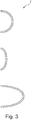
- Fig. 3 illustrates a cross-section of different vibration dampening elements 7. As illustrated the cross-section is ach-shaped. It should be understood, that the substantially flat vibration dampening element 107 illustrated in Fig. 2 could be substituted with any one of the vibration dampening elements 7 of Fig. 3 .
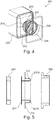
- Fig. 4 illustrates a receiver assembly 201 in an exploded view.
- the receiver assembly 201 comprises a receiver 202 and an assembly housing 203.
- the receiver 202 is arranged within the assembly housing 203 comprising an assembly sound outlet 206.
- the receiver 202 comprises a sound outlet 205 configured to outlet sound from the receiver 202.
- the sound outlet 205 is arranged in communication with the assembly sound outlet 206.
- a vibration dampening element 207 connects the sound outlet 205 and the assembly sound outlet 206 and is compliant to reduce vibrations from the receiver 202 to the assembly housing 203.
- the receiver assembly 201 further comprises two stiffening members 209, 210.
- the stiffening members 209, 210 are more rigid than the vibration dampening element 207.
- connection of the vibration dampening element to the receiver 202 and to the assembly housing 203 may be facilitated.
- Fig. 5 illustrates the vibration dampening element 207 and the two stiffening members 209, 210 in more details.
- the vibration dampening element 207 can be attached to the stiffening members 209, 210, respectively at the attachment surfaces 211, 212.
- the attachment surfaces 211, 212 are also applicable for attached directly to the receiver 201 and the assembly housing 203, respectively, if the stiffening member 209, 210 are not used.
- the stiffening members 209 and 210 are not required to ensure decoupling or ensure propagation of sound. They may facilitate assembling of the receiver assembly.
- the vibration dampening element 207 forms a first attachment plane 211 in which it can be attached to the receiver 201 and a second attachment plane 212 in which it can be attached to the assembly housing 203.
- the first and second attachment planes 211, 212 are parallel and off-set relative to each other, so that the vibration dampening element 207 extends in a direction transverse to the first and second attachment planes 211, 212.
- the vibration dampening element 207 has an arc-shaped cross-section 207A (see more details in Fig. 7 ) in a plane perpendicular to the attachment planes 211, 212.
- Fig. 6 illustrates a cross-section through the receiver assembly 201 of Fig. 4 .
- the receiver assembly 201 comprises a receiver 202 and an assembly housing 203.
- the receiver 202 comprises a sound outlet 205 configured to outlet sound from the receiver 202.
- the sound outlet 205 is arranged in communication with the assembly sound outlet 206.
- a vibration dampening element 207 connects the sound outlet 205 and the assembly sound outlet 206.
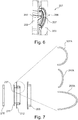
- Fig. 7 illustrates the vibration dampening element 207 and the stiffening members 209, 210, also illustrated in Fig. 5 .
- Fig. 7 illustrates details of a vibration dampening element 207.
- the vibration dampening element 207 forms a first attachment plane 211 in which it can be attached to the receiver 201 or the stiffening member 210 and a second attachment plane 212 in which it can be attached to the assembly housing 203 or the stiffening member 209.
- the first and second attachment planes 211, 212 are parallel and off-set relative to each other.
- the vibration dampening element 207 has an arc-shaped cross-section 207A in a plane being perpendicular to the attachment planes 211, 212.
- the right side part of Fig. 7 illustrates three different arc-shaped sections 7A of the vibration dampening element 7.
- Figs. 8A-8C illustrate different embodiments of a vibration dampening element 207, 307. 407.
- the vibration dampening elements are similar except for their shape which is circular, oval, and rectangular.
- Figs. 8A-8C also illustrate corresponding stiffening elements 209, 210, 309, 310, 409, 410.
- Figs. 9A and 9B illustrate different embodiments of a receiver assembly 201, 401 in exploded views.
- the receiver assembly 201, 401 comprises a receiver 202, 402 and an assembly housing 203, 403.
- a vibration dampening element 207, 401 connects the sound outlet 205, 405 and the assembly sound outlet 206, 406. Furthermore, the receiver assembly 201, 401 comprises stiffening members 209, 210, 409, 410.
- Fig. 10 illustrates an embodiment of a receiver assembly 1 in 3D.
- the receiver assembly 1 comprises a receiver 2 and an assembly housing 3 (only being partly visible).
- the receiver 2 is arranged within the assembly housing 3 which comprising an assembly sound outlet (not shown).
- the receiver 2 comprises a sound outlet 5 configured to outlet sound from the receiver 2.
- the sound outlet 5 is arranged in communication with the assembly sound outlet 6.
- a vibration dampening element 7 connects the sound outlet 5 and the assembly sound outlet 6 and is compliant to reduce vibrations from the receiver 2 to the assembly housing 3.
- the vibration dampening element 7 comprises a through hole 8 allowing sound to propagate through the vibration dampening element. Furthermore, the receiver assembly 1 comprises stiffening members 9, 10 to which the vibration dampening element 7 is attached.
- suspension elements 7' are arranged in the assembly housing 3.
- the suspension elements 7' connect the receiver 2 and the assembly housing 3.
- the suspension elements 7' are similar to the vibration dampening element 7, however without a through hole. Due to the compliance of the suspension element 7', the receiver 2 is movable arranged in the assembly housing 3.
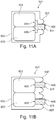
- Figs. 11A and 11B illustrate different embodiments of a receiver assembly 501, 601 each comprising two receivers 502, 602.
- the receivers 502, 602 are arranged within the assembly housing 503, 603 which comprising an assembly sound outlet 506, 606.
- the receivers 502 are identical, and also the receivers 602 are identical.
- the receivers 502, 602 each comprises a sound outlet 505, 605 configured to outlet sound from the receivers 502, 602.
- the sound outlets 505, 605 are arranged in communication with the assembly sound outlet(s) 506, 606 via a spout part 511, 611.
- a vibration dampening element 507, 607 connects the sound outlets 505, 605 and the assembly sound outlet(s) 506, 606 via the spout part 511, 611.
- the vibration dampening element 507, 607 is compliant to reduce vibrations from the receivers 502, 602 to the assembly housing 503, 603.
- the spout part 511 is a common spout part which connects the sound outlet 505 from each of the receivers 502 to the assembly sound outlet 506.
- the embodiment illustrated in Fig. 11B comprises two separate spout parts 611 each connecting a sound outlet 605 of the receivers 602 to an assembly sound outlet 606.
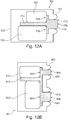
- Figs. 12A and 12B illustrate different embodiments of a receiver assembly 701, 801 each comprising two receivers 702, 802.
- the receivers 702, 802 are arranged within the assembly housing 703, 803 which comprising an assembly sound outlet 706, 806.
- the receivers 702 are of different types.
- the receivers 802 are of different types.
- the receivers 702, 802 each comprises a sound outlet 705, 805 configured to outlet sound from the receivers 702, 802.
- the sound outlets 705, 805 are arranged in communication with the assembly sound outlet(s) 706, 806 via a joiner 712, 812.
- a vibration dampening element 707, 807 connects the sound outlets 705, 805 and the assembly sound outlet(s) 706, 806 via the joiner 712, 812.
- the vibration dampening element 707, 807 is compliant to reduce vibrations from the receivers 702, 802 to the assembly housing 703, 803.
- the joiner 712, 812 comprises a mounting plate portion 713, 813 having a first surface and an opposite second surface.
- the mounting plate portion 713, 813 comprises first engagement means (not shown) for engaging the upper receiver 702 at the first surface, and second engagement means (not shown) for engaging the lower receiver 702 at the second surface.
- joiner 712, 812 comprise a spout portion 714, 814 forming at least one sound channel (not shown) extending through the spout portion.
- the sound outlets 705, 805 can be arranged in communication with one of the at least one sound channels extending through the spout portion 714, 814.
- the joiner 712 comprises a common spout portion 714 to provide communication between the sound outlet 705 of each of the receivers 702 and assembly sound outlet 706.
- the embodiment illustrated in Fig. 12B comprises a joiner 812 with two separate spout portions 814 to provide communication between a sound outlet 805 of the receivers 802 and an assembly sound outlet 806.
Landscapes
- Physics & Mathematics (AREA)
- Engineering & Computer Science (AREA)
- Acoustics & Sound (AREA)
- Signal Processing (AREA)
- Health & Medical Sciences (AREA)
- Otolaryngology (AREA)
- General Health & Medical Sciences (AREA)
- Neurosurgery (AREA)
- Soundproofing, Sound Blocking, And Sound Damping (AREA)
- Accessory Devices And Overall Control Thereof (AREA)
Description
- The present invention relates to a receiver assembly comprising a receiver and an assembly housing. The receiver assembly comprises a vibration dampening element to reduce vibrations from the receiver to the assembly housing.
- When producing sound, a receiver also creates vibrations. Such vibrations are unwanted and may put a limit on the performance of a personal audio device, such as a hearing aid. This is due to the fact that the vibrations can be picked up by the microphone and amplified again; i.e. feedback.
-
-
EP 3 051 841 - Prior art documents
WO 01/43498 EP 2 073 572US 2015/110328 disclose different suspension members, all being solid; i.e. with a significant material thickness of the wall defining the suspension members compared to the size of the suspension members. These suspension members thereby only provide limited reduction of vibrations from the receiver to the assembly housing. - Prior art document
WO 01/43498 -
EP 2 073 572 -
US 2015/110328 discloses a suspension for a hearing device receiver which includes: a receiver holding part; and a damping structure with a body and a receiver base, the body comprising a first body part, the damping structure having an inner surface forming a sound duct. The sound duct extends through the first body part. The damping structure has a first opening at a first sound duct end, the first opening configured for connecting an output port of a receiver, and the damping structure has a second opening at a second sound duct end. The sound duct provides a sound path for conveying sound energy from the receiver through the damping structure to the second opening. - It is an object of embodiments of the invention to provide an improved receiver assembly.
- It is a further object of embodiments of the invention to provide a receiver assembly where vibrations from the receiver to the assembly housing can be reduced.
- According to a first aspect, the invention provides a receiver assembly comprising a receiver and an assembly housing;
the receiver comprising a sound outlet configured to outlet sound from the receiver and being arranged at least partly within the assembly housing,
the assembly housing comprising an assembly sound outlet,
wherein the sound outlet is arranged in communication with the assembly sound outlet for outlet of sound from the receiver via the assembly sound outlet, and wherein a vibration dampening element connects the sound outlet and the assembly sound outlet, the vibration dampening element being formed by an elastic foil and being compliant to reduce vibrations from the receiver to the assembly housing. - The receiver may be adapted to form part of any personal audio device, such as a hearing aid, such as a Behind-the-Ear (BTE) device, an In the Ear (ITE) device, a Receiver in the Canal (RIC) device, or any other personal audio device, such as headphones, earphones, and other earpieces. In the context of the present invention, the term "hearing aid" shall be understood as an electromagnetic device which is adapted to amplify and modulate sound and to output this sound to a user, such as into the ear canal of a user.
- However, it should further be understood, that the receiver in one embodiment may be a balanced armature receiver, whereas the receiver in other embodiments may also comprise other transducer technologies, such as e.g. piezo technology, moving coil, electrostatic receiver technologies, and microphones, such as electret, MEMS, etc.
- Thus, the receiver may be adapted to receive an electrical signal and output a corresponding audio signal through the sound outlet.
- It should further be understood, that the assembly may comprise more than one receiver, such as two, three, or more receivers. Assemblies comprising more than one receiver may as an example comprise receivers of a single type, such as two balanced armature receivers, or may alternatively comprise receivers of different types, such as a balanced armature receiver and an electrostatic receiver.
- The receiver may comprise a magnet assembly and an armature. The magnet assembly may be arranged to provide a magnetic field in an air gap, and the armature may comprise at least one leg which extends through the air gap.
- The armature may be made from any type of material, element and/or assembly able to guide or carry a magnetic flux. The armature may be electrically conducting or not.
- The receiver may further comprise a diaphragm which is operationally attached to the armature, such that movement of the armature is transferred to the diaphragm. It will be appreciated that movement of the diaphragm causes sound waves to be generated. In one embodiment, the diaphragm is operationally attached to the armature by means of a diaphragm connecting member, such as a drive pin. Alternatively, the diaphragm may itself be attached to the armature.
- The diaphragm may comprise a plastic material, such as a polymer, or alternatively a metal material such as aluminium, nickel, stainless steel, or any other similar material. It should however be understood, that the diaphragm may comprise a plurality of materials. The diaphragm may divide the chamber into two chambers, such as a front volume and a back volume.
- The assembly housing may be located in a shell made of a soft material, such as silicone, thereby improving the comfort. To improve comfort further, an individual shell may be made for each user to fit the ear of the user.
- The receiver may be formed as a substantially box-shaped element. Other shaped may however also be applicable.
- The assembly housing may likewise be formed as a substantially box-shaped element. However, other shapes may also be applicable, such as shapes which fit the ear of a user.
- The receiver is arranged at least partly within the assembly housing. Thus, the receiver may have an outer surface facing toward an inner surface of the assembly housing. The inner and outer surfaces may each comprise a first surface, a second surface, a third surface, and even more surface. As an example, a substantially box-shaped receiver may comprise six outer surfaces.
- If the receiver and/or assembly housing is substantially box-shaped it should be understood, that the edges and corners may be rounded off. This may also be the case for receivers and assembly housings in other shapes.
- The sound outlet of the receiver is arranged in communication with the assembly outlet for outlet of sound from the receiver via the assembly sound outlet. By arranging the sound outlet in communication with the assembly outlet, vibrations from the receiver may be transferred to the assembly housing.
- To reduce the risk of transferring such vibrations, a vibration dampening element connects the sound outlet and the assembly sound outlet. The vibration dampening element is compliant to enable reduction of vibrations. The vibration dampening element is formed by an elastic foil. This is in contradiction to traditional injection moulded sound channels of rubber (silicone) which do not offer the same compliance.
- In one embodiment, the vibration dampening element is compliant in at least two directions.
- In the context of the present invention, the term "dampen vibration" should be understood as reducing vibration by decoupling the receiver from the assembly housing. It should be understood, that some vibration may still be present.
- In the context of the present invention, the term "connects" not only covers embodiments where the vibration dampening element is in contact with the receiver and the assembly housing. The vibration dampening element may also connect the sound outlet and the assembly sound outlet by being in contact with the receiver and the assembly housing by an additional element.
- The vibration dampening element may be more compliant in the direction of the sound outlet that in directions transverse to the sound outlet. This may be particularly interesting for receivers which primarily produce vibrations in the direction of the sound outlet, such as a dual receiver. However, it should understood, that the dampening element may in an alternative embodiment be equally compliant in at least two directions.
- The vibration dampening element may comprise at least one through hole allowing sound to propagate through the vibration dampening element.
- To more effectively decouple the vibrations, the receiver may be movably arranged in the assembly housing, e.g. by suspending the receiver in the assembly housing by use of a suspension structure.
- The vibration dampening element may seal a passage between the sound outlet and the assembly sound outlet in order to facilitate outlet of sound from the receiver via the assembly outlet, and to prevent sound propagation in a space between an outer surface of the receiver and in inner surface of the assembly housing.
- In one embodiment this may be achieved by arranging the vibration dampening element so that it seals a passage between an outer surface of one sound outlet and the assembly sound outlet and an inner surface of the other one of the sound outlet and the assembly sound outlet.
- In one example, the sound outlet and the assembly sound outlet are provided as two elongated sound channels. The diameter of one of these sound channels may be smaller than the diameter of the other one of the sound channel to facilitate insertion of one sound channel at least partly into the other sound channel. In this embodiment the vibration dampening element may be arranged circumferential around the smaller sound channel and circumferential along the inner surface of the other sound channel, thereby sealing the passage between the two sound outlets.
- It should be understood that the sound outlet, the assembly sound outlet, and the sound channels may have a circular cross-section. However, other cross-sectional shapes may also be applied. As an example, the cross-section may be oval or rectangular, or of any other arbitrary shape.
- In an alternative embodiment, the vibration dampening element forms a sound channel from the sound outlet to the assembly sound outlet. In this embodiment the vibration dampening element may be attached directly to the receiver and to the assembly housing. It should however be understood, that the vibration dampening element may be attached to at least one of the receiver and the assembly housing by one or more connecting element, e.g. to facilitate connection hereof.
- The vibration dampening element is made of a foil, such as a thin rubbery foil to achieve a sufficient compliance.
- The vibration dampening element may be made in one piece. Furthermore, the vibration dampening element may be made of one single material.
- The vibration dampening element may as an example be formed by a polymer material or by a metal, or combinations hereof.
- By using a foil material, the vibration dampening element may be made by thermoforming processes. The foil material may be rubbery TPU (Thermoplastic polyurethane), PU (Polyurethane), PET (Polyethylene terephthalate), PEEK (Polyether ether ketone), and similar materials.
- The foil may have a material thickness in the range of 4-40 microns to increase the flexibility of the vibration dampening element.
- The vibration dampening element may be attached to the receiver and/or the assembly housing by use of different processes, such as laminating, adhesively, ultrasonic welding, clamping, etc.
- To facilitate attachment of the vibration dampening element to the receiver and the assembly housing, the vibration dampening element forms a first attachment plane in which it can be attached to the receiver and forms a second attachment plane in which it can be attached to the assembly housing. The first and second attachment planes may be off-set relative to each other, whereby the vibration dampening element extends in a direction transverse to the first and second attachment planes.
- The first and second attachment planes are parallel to each other.
- The vibration dampening element has an arc-shaped cross-section in a plane being perpendicular to the attachment planes. The arc-shaped cross-section may increase the efficiency of the vibration dampening element, as decoupling may be facilitated. It should be understood, that the vibration dampening element may form more than one arc-shaped cross-section, thereby forming a wave-shape in at least one cross-section.
- It should however be understood, that as an alternative to an arc-shaped cross-section in an example not falling under the scope of the appended claims, the vibration dampening element may have a square-shaped or trapezoid cross-section in a plane being perpendicular to the attachment planes. These cross-sections may also increase the efficiency of the vibration dampening element.
- It should be understood, that the vibration dampening element may be formed as a substantially flat element, thereby extending parallel to the sound outlet. This embodiment may be of particular interest in embodiments where at least one of the sound outlet and the assembly outlet is provided as an elongated sound channel. It should however be understood, that the vibration dampening element may also have an arc-shaped cross-section in these embodiments.
- In one embodiment, the receiver may comprise an additional sound outlet, and the assembly housing may comprise an additional assembly sound outlet, where the additional sound outlet is arranged in communication with the additional assembly sound outlet for outlet of sound from the receiver via the additional assembly sound outlet. In this embodiment, an additional vibration dampening element being compliant may connect the additional sound outlet and the additional assembly sound outlet to reduce vibrations from the receiver to the assembly housing. The receiver may be a module of two receivers or a dual receiver with two sound outlets.
- It should be understood, that the receiver may be traditional dual receiver with a common sound outlet, where the common sound outlet of the dual receiver forms the sound outlet.
- The receiver assembly may comprise at least one stiffening member which may be more rigid than the vibration dampening element and which may connect the vibration dampening element to at least one of the receiver and the assembly housing. By providing a stiffening member with a compliance being lower than the compliance of the vibration dampening element, connection of the vibration dampening element to the receiver and/or to the assembly housing may be facilitated.
- The receiver assembly may further comprise an air path way configured to guide air away from the receiver to reduce pressure induced vibrations. The air path way may constitute an airtight path from the receiver to the outside of the assembly housing while at the same time not interfering with the decoupling of the receiver from the assembly housing.
- The vibration dampening element may be adhesively attached to at least one of the receiver and the assembly housing. Alternatively, the vibration dampening element may be welded to at least one of the receiver and the assembly housing, e.g. by use of ultrasonic welding. As a further alternative, the vibration dampening element may be clamped or laminated to at least one of the receiver and the assembly housing. It should be understood, that the way of attachment may be by use of one method to the receiver and may be by an alternative method to the assembly housing.
- As the receiver assembly may be exposed to mechanical shocks, e.g. if dropped on the floor, it may be an advantage if the receiver assembly further comprises a shock protection element arranged in the assembly housing, as this may protect the receiver from impact from the assembly housing. The shock protection element may have a higher compliance than the vibration dampening element.
- To ensure sufficient efficiency, the shock protection element may be made of a soft material such as a foam. The shock protection effect may be achieved by a combination of the physical properties and the dimensions of the shock protection element. As an example, a shock protection element in the form of a foam with micro pores provided at a thickness of 0.4 mm may provide the same shock protection as a shock protection element of latex; i.e. a polymer, provided at a thickness of 0.25 mm, since these shock protection elements have the same mechanical stiffness due to the combination of their mechanical properties and dimensions.
- It should be understood that other materials and/or thicknesses and/or combinations of materials and/or thicknesses may also be possible.
- The shock protection element may be attached to at least one of an outer surface of the receiver and an inner surface of the assembly housing. The shock protection element may only be in contact with one of the receiver and the assembly housing. However, during a mechanical shock it may touch both the receiver and the assembly housing to thereby lower the impact of a shock.
- It should be understood, that the receiver assembly may comprise a plurality of shock protection elements. As an example, a shock protection element may be arranged on each side of the receiver to protect the receiver from impact on each side.
- In one embodiment, the receiver assembly may further comprise an additional receiver comprising an additional sound outlet and a joiner. The joiner may comprise a spout portion forming at least one sound channel extending through the spout portion and a mounting plate portion having a first surface and an opposite second surface. The mounting plate portion may comprise first engagement means for engaging the receiver at the first surface, and second engagement means for engaging the additional receiver at the second surface. When arranging the receiver and the additional receiver on opposite sides of the mounting plate portion, the sound outlet and the additional sound outlet can be aligned with one of the at least one sound channels extending through the spout portion. The vibration dampening element may connect the sound outlet and the additional sound outlet to the assembly sound outlet via the spout portion.
- By use of a joiner assembling, positioning and alignment of the receiver and the additional receiver may be facilitated and may in some embodiments even be carried out without the use of additional fixture elements.
- According to a second aspect, the invention provides a personal audio device comprising a receiver assembly according to the first aspect of the invention, wherein the receiver is configured to generate sound whereby it vibrates within a frequency range of 10 Hz-20 kHz, and wherein the vibration dampening elements is configured to elastically deform to thereby reduce transmission of vibration to the assembly housing.
- The frequency range may depend on the type of personal audio device in which the receiver is used.
- It should be understood, that a skilled person would readily recognise that any feature described in combination with the first aspect of the invention could also be combined with the second aspect of the invention, and vice versa.
- The receiver assembly according to the first aspect of the invention is very suitable for the personal audio device according to the second aspect of the invention. The remarks set forth above in relation to the receiver assembly are therefore equally applicable in relation to the personal audio device.
- Embodiments of the invention will now be further described with reference to the drawings, in which:
-
Fig. 1 schematically illustrates a receiver assembly according to the invention, -
Fig. 2 schematically illustrates an alternative embodiment of a receiver assembly according to the invention, -
Fig. 3 illustrates different vibration dampening element, -
Fig. 4 illustrates a receiver assembly in an exploded view with details of a sound outlet, -
Fig. 5 illustrates a vibration dampening element and two stiffening members, -
Fig. 6 illustrates a cross-section of a receiver assembly with details of a sound outlet, -
Fig. 7 illustrates details of a vibration dampening element, -
Figs. 8A-8C illustrate different embodiments of a vibration dampening element, -
Figs. 9A and 9B illustrate different embodiments of a receiver assembly in an exploded view, -
Fig. 10 illustrates an alternative embodiment of a receiver assembly, -
Figs. 11A and 11B illustrate different embodiments of a receiver assembly comprising two receivers, and -
Figs. 12A and 12B illustrate different embodiments of a receiver assembly comprising two receivers. - The invention is set out in the appended set of claims.
-
Fig. 1 schematically illustrates areceiver assembly 1 according to the invention. Thereceiver assembly 1 comprises areceiver 2 and anassembly housing 3. - The
receiver 2 comprises a magnet assembly (not shown), an armature (not shown), adiaphragm 4 being operationally attached to the armature, and asound outlet 5 configured to outlet sound from thereceiver 2. It should be understood, that other types of receivers are equally applicable for the invention. - The
receiver 1 is arranged within theassembly housing 3 comprising anassembly sound outlet 6. - The
sound outlet 5 is arranged in communication with theassembly sound outlet 6 for outlet of sound from thereceiver 2 via theassembly sound outlet 6. - A
vibration dampening element 7 connects thesound outlet 5 and theassembly sound outlet 6 and is compliant to reduce vibrations from thereceiver 2 to theassembly housing 3. In the illustrated embodiment, thevibration dampening element 7 has an arc-shapedcross-section 7A along the circumference of the sound outlet and the assembly sound outlet. - The
vibration dampening element 7 comprises a throughhole 8 allowing sound to propagate through the vibration dampening element. - Additionally, three suspension elements 7' are arranged in the
assembly housing 3 and connect thereceiver 2 and theassembly housing 3. The suspension elements 7' are similar to thevibration dampening element 7, however without a through hole. Due to the compliance of the suspension element 7', thereceiver 2 is movable arranged in theassembly housing 3. -
Fig. 2 schematically illustrates an alternative embodiment of areceiver assembly 101 according to the invention. Thereceiver assembly 101 comprises areceiver 102 and anassembly housing 103. - The
receiver 102 comprises asound outlet 105 configured to outlet sound from thereceiver 102. Thereceiver 102 is arranged within theassembly housing 103 comprising anassembly sound outlet 106. - The
sound outlet 105 is arranged in communication with theassembly sound outlet 106 for outlet of sound from thereceiver 102 via theassembly sound outlet 106. - A
vibration dampening element 107 connects thesound outlet 105 and theassembly sound outlet 106 and is compliant to reduce vibrations from thereceiver 102 to theassembly housing 103. - In the illustrated embodiment, the
sound outlet 105 and theassembly sound outlet 106 are provided as two elongated sound channels 105', 106'. The diameter of assembly sound channel 106' is smaller than the diameter of thesound channel 105 to facilitate partly insertion of the assembly sound channel 106' into the sound channel 105'. Thevibration dampening element 107 is formed as a substantially flat element extending parallel to thesound outlet 105 and theassembly sound outlet 106 and is arranged circumferential around the assembly sound channel 106' and circumferential along the inner surface of the sound channel 105', thereby sealing the passage between the twosound outlets - It should be understood, that the diameter of assembly sound channel 106' in an alternative embodiment could be equal to the diameter of the sound channel 105' as the vibration dampening element may be arranged at an end portion of each of the sound channel 105' and the assembly sound channel 106' which may be arranged end to end with a vibration dampening element in between.
- The
vibration dampening element 107 comprises a throughhole 108 through which the assembly sound channel extends 106' thereby allowing sound to propagate through the vibration dampening element. -
Fig. 3 illustrates a cross-section of differentvibration dampening elements 7. As illustrated the cross-section is ach-shaped. It should be understood, that the substantially flatvibration dampening element 107 illustrated inFig. 2 could be substituted with any one of thevibration dampening elements 7 ofFig. 3 . -
Fig. 4 illustrates areceiver assembly 201 in an exploded view. Thereceiver assembly 201 comprises areceiver 202 and anassembly housing 203. Thereceiver 202 is arranged within theassembly housing 203 comprising anassembly sound outlet 206. - The
receiver 202 comprises asound outlet 205 configured to outlet sound from thereceiver 202. Thesound outlet 205 is arranged in communication with theassembly sound outlet 206. - A
vibration dampening element 207 connects thesound outlet 205 and theassembly sound outlet 206 and is compliant to reduce vibrations from thereceiver 202 to theassembly housing 203. - In the illustrated embodiment, the
receiver assembly 201 further comprises two stiffeningmembers members vibration dampening element 207. By providing the stiffeningmembers vibration dampening element 207, connection of the vibration dampening element to thereceiver 202 and to theassembly housing 203 may be facilitated. -
Fig. 5 illustrates thevibration dampening element 207 and the two stiffeningmembers vibration dampening element 207 can be attached to the stiffeningmembers receiver 201 and theassembly housing 203, respectively, if the stiffeningmember members - As illustrated in
Fig. 5 , thevibration dampening element 207 forms afirst attachment plane 211 in which it can be attached to thereceiver 201 and asecond attachment plane 212 in which it can be attached to theassembly housing 203. The first and second attachment planes 211, 212 are parallel and off-set relative to each other, so that thevibration dampening element 207 extends in a direction transverse to the first and second attachment planes 211, 212. - The
vibration dampening element 207 has an arc-shapedcross-section 207A (see more details inFig. 7 ) in a plane perpendicular to the attachment planes 211, 212. -
Fig. 6 illustrates a cross-section through thereceiver assembly 201 ofFig. 4 . As mentioned above, thereceiver assembly 201 comprises areceiver 202 and anassembly housing 203. - The
receiver 202 comprises asound outlet 205 configured to outlet sound from thereceiver 202. Thesound outlet 205 is arranged in communication with theassembly sound outlet 206. Furthermore, avibration dampening element 207 connects thesound outlet 205 and theassembly sound outlet 206. -
Fig. 7 illustrates thevibration dampening element 207 and the stiffeningmembers Fig. 5 .Fig. 7 illustrates details of avibration dampening element 207. Thevibration dampening element 207 forms afirst attachment plane 211 in which it can be attached to thereceiver 201 or the stiffeningmember 210 and asecond attachment plane 212 in which it can be attached to theassembly housing 203 or the stiffeningmember 209. The first and second attachment planes 211, 212 are parallel and off-set relative to each other. Thevibration dampening element 207 has an arc-shapedcross-section 207A in a plane being perpendicular to the attachment planes 211, 212. The right side part ofFig. 7 , illustrates three different arc-shapedsections 7A of thevibration dampening element 7. -
Figs. 8A-8C illustrate different embodiments of avibration dampening element Figs. 8A-8C also illustrate correspondingstiffening elements -
Figs. 9A and 9B illustrate different embodiments of areceiver assembly receiver assembly receiver assembly housing 203, 403. - A
vibration dampening element sound outlet 205, 405 and theassembly sound outlet 206, 406. Furthermore, thereceiver assembly members -
Fig. 10 illustrates an embodiment of areceiver assembly 1 in 3D. Thereceiver assembly 1 comprises areceiver 2 and an assembly housing 3 (only being partly visible). Thereceiver 2 is arranged within theassembly housing 3 which comprising an assembly sound outlet (not shown). - The
receiver 2 comprises asound outlet 5 configured to outlet sound from thereceiver 2. Thesound outlet 5 is arranged in communication with theassembly sound outlet 6. - A
vibration dampening element 7 connects thesound outlet 5 and theassembly sound outlet 6 and is compliant to reduce vibrations from thereceiver 2 to theassembly housing 3. - The
vibration dampening element 7 comprises a throughhole 8 allowing sound to propagate through the vibration dampening element. Furthermore, thereceiver assembly 1 comprises stiffeningmembers 9, 10 to which thevibration dampening element 7 is attached. - Additionally, three suspension elements 7' are arranged in the
assembly housing 3. The suspension elements 7' connect thereceiver 2 and theassembly housing 3. The suspension elements 7' are similar to thevibration dampening element 7, however without a through hole. Due to the compliance of the suspension element 7', thereceiver 2 is movable arranged in theassembly housing 3. -
Figs. 11A and 11B illustrate different embodiments of areceiver assembly receivers receivers assembly housing assembly sound outlet receivers 502 are identical, and also thereceivers 602 are identical. - The
receivers sound outlet receivers sound outlets spout part - A
vibration dampening element sound outlets spout part vibration dampening element receivers assembly housing - In the embodiment illustrated in
Fig. 11A , thespout part 511 is a common spout part which connects thesound outlet 505 from each of thereceivers 502 to theassembly sound outlet 506. - The embodiment illustrated in
Fig. 11B , comprises twoseparate spout parts 611 each connecting asound outlet 605 of thereceivers 602 to anassembly sound outlet 606. -
Figs. 12A and 12B illustrate different embodiments of areceiver assembly receivers receivers assembly housing 703, 803 which comprising anassembly sound outlet receivers 702 are of different types. Also thereceivers 802 are of different types. - The
receivers sound outlet receivers sound outlets joiner - A
vibration dampening element sound outlets joiner vibration dampening element receivers assembly housing 703, 803. - The
joiner plate portion plate portion upper receiver 702 at the first surface, and second engagement means (not shown) for engaging thelower receiver 702 at the second surface. - Furthermore, the
joiner spout portion receivers plate portion sound outlets spout portion - In the embodiment illustrated in
Fig. 12A , thejoiner 712 comprises acommon spout portion 714 to provide communication between thesound outlet 705 of each of thereceivers 702 andassembly sound outlet 706. - The embodiment illustrated in
Fig. 12B comprises ajoiner 812 with twoseparate spout portions 814 to provide communication between asound outlet 805 of thereceivers 802 and anassembly sound outlet 806.
Claims (12)
- A receiver assembly (1, 101, 201, 401, 501, 601, 701, 801) comprising a receiver (2, 102, 202, 402, 502, 602, 702, 802) and an assembly housing (3, 103, 203, 403, 503, 603, 703, 803);
the receiver (2, 102, 202, 402, 502, 602, 702, 802) comprising a sound outlet (5, 105, 105', 205, 405, 505, 605, 705, 805) configured to outlet sound from the receiver and being arranged at least partly within the assembly housing (3, 103, 203, 403, 503, 603, 703, 803),
the assembly housing (3, 103, 203, 403, 503, 603, 703, 803) comprising an assembly sound outlet (6, 106, 106', 206, 406, 506, 606, 706, 806),
wherein the sound outlet (5, 105, 105', 205, 405, 505, 605, 705, 805) is arranged in communication with the assembly sound outlet (6, 106, 106', 206, 406, 506, 606, 706, 806) for outlet of sound from the receiver (2, 102, 202, 402, 502, 602, 702, 802) via the assembly sound outlet (6, 106, 106', 206, 406, 506, 606, 706, 806), and wherein a vibration dampening element (7, 107, 207, 307, 407, 507, 607, 707, 807) connects the sound outlet (5, 105, 105', 205, 405, 505, 605, 705, 805) and the assembly sound outlet (6, 106, 106', 206, 406, 506, 606, 706, 806),
characterised in that the vibration dampening element (7, 107, 207, 307, 407, 507, 607, 707, 807) forms a first attachment plane (211) in which it is attached to the receiver (2, 102, 202, 402, 502, 602, 702, 802) and forms a second attachment plane (212) in which it is attached to the assembly housing (3, 103, 203, 403, 503, 603, 703, 803), and wherein the first and second attachment planes (211, 212) are off-set relative to each other and are parallel, and in that the vibration dampening element (7, 107, 207, 307, 407, 507, 607, 707, 807) has an arc-shaped cross-section (207A) in a plane being perpendicular to the attachment planes and is formed by an elastic foil and is compliant to reduce vibrations from the receiver (2, 102, 202, 402, 502, 602, 702, 802) to the assembly housing (3, 103, 203, 403, 503, 603, 703, 803). - A receiver assembly (1, 101, 201, 401, 501, 601, 701, 801) according to claim 1, wherein the receiver (2, 102, 202, 402, 502, 602, 702, 802) is movably arranged in the assembly housing (3, 103, 203, 403, 503, 603, 703, 803).
- A receiver assembly (1, 101, 201, 401, 501, 601, 701, 801) according to claim 1 or 2, wherein the vibration dampening element (7, 107, 207, 307, 407, 507, 607, 707, 807) seals a passage between an outer surface of one of the sound outlet (5, 105, 105', 205, 405, 505, 605, 705, 805) and the assembly sound outlet (6, 106, 106', 206, 406, 506, 606, 706, 806)and an inner surface of the other one of the sound outlet (5, 105, 105', 205, 405, 505, 605, 705, 805) and the assembly sound outlet (6, 106, 106', 206, 406, 506, 606, 706, 806).
- A receiver assembly (1, 101, 201, 401, 501, 601, 701, 801) according to any of the preceding claims, wherein the vibration dampening element (7, 107, 207, 307, 407, 507, 607, 707, 807) forms a sound channel from the sound outlet (5, 105, 105', 205, 405, 505, 605, 705, 805) to the assembly sound outlet (6, 106, 106', 206, 406, 506, 606, 706, 806).
- A receiver assembly (1, 101, 201, 401, 501, 601, 701, 801) according to any of the preceding claims, wherein the receiver (2, 102, 202, 402, 502, 602, 702, 802) comprises an additional sound outlet (5, 105, 105', 205, 405, 505, 605, 705, 805), and wherein the assembly housing (3, 103, 203, 403, 503, 603, 703, 803) comprises an additional assembly sound outlet (6, 106, 106', 206, 406, 506, 606, 706, 806), the additional sound outlet (5, 105, 105', 205, 405, 505, 605, 705, 805) being arranged in communication with the additional assembly sound outlet (6, 106, 106', 206, 406, 506, 606, 706, 806) for outlet of sound from the receiver (2, 102, 202, 402, 502, 602, 702, 802) via the additional assembly sound outlet (6, 106, 106', 206, 406, 506, 606, 706, 806), and wherein an additional vibration dampening element (7, 107, 207, 307, 407, 507, 607, 707, 807) connects the additional sound outlet (5, 105, 105', 205, 405, 505, 605, 705, 805) and the additional assembly sound outlet (6, 106, 106', 206, 406, 506, 606, 706, 806) and is compliant to reduce vibrations from the receiver (2, 102, 202, 402, 502, 602, 702, 802) to the assembly housing (3, 103, 203, 403, 503, 603, 703, 803).
- A receiver assembly (1, 101, 201, 401, 501, 601, 701, 801) according to any of the preceding claim, further comprising at least one stiffening member (9, 10, 209, 210, 309, 310, 409, 410) being more rigid than the vibration dampening element (7, 107, 207, 307, 407, 507, 607, 707, 807) and connecting the vibration dampening element (7, 107, 207, 307, 407, 507, 607, 707, 807) to at least one of the receiver (2, 102, 202, 402, 502, 602, 702, 802) and the assembly housing (3, 103, 203, 403, 503, 603, 703, 803).
- A receiver assembly (1, 101, 201, 401, 501, 601, 701, 801) according to any of the preceding claims, further comprising an air path way configured to guide air away from the receiver (2, 102, 202, 402, 502, 602, 702, 802) to reduce pressure induced vibrations.
- A receiver assembly (1, 101, 201, 401, 501, 601, 701, 801) according to any of the preceding claims, wherein the vibration dampening element (7, 107, 207, 307, 407, 507, 607, 707, 807) is welded to at least one of the receiver (2, 102, 202, 402, 502, 602, 702, 802) and the assembly housing (3, 103, 203, 403, 503, 603, 703, 803).
- A receiver assembly (1, 101, 201, 401, 501, 601, 701, 801) according to any of the preceding claims, wherein the vibration dampening element (7, 107, 207, 307, 407, 507, 607, 707, 807) is formed by a polymer material or by a metal, or combinations hereof.
- A receiver assembly (1, 101, 201, 401, 501, 601, 701, 801) according to any of the preceding claim, further comprising a shock protection element arranged in the assembly housing (3, 103, 203, 403, 503, 603, 703, 803), the shock protection element having a higher compliance than the vibration dampening element (7, 107, 207, 307, 407, 507, 607, 707, 807).
- A receiver assembly (1, 101, 201, 401, 501, 601, 701, 801) according to any of the preceding claims, further comprising:- an additional receiver (2, 102, 202, 402, 502, 602, 702, 802) comprising an additional receiver sound outlet (5, 105, 105', 205, 405, 505, 605, 705, 805); and- a joiner (712, 812) comprising a spout portion (714, 814) forming at least one sound channel extending through the spout portion (713, 813) and a mounting plate portion having a first surface and an opposite second surface; the mounting plate portion comprising first engagement means for engaging the receiver (2, 102, 202, 402, 502, 602, 702, 802) at the first surface, and second engagement means for engaging the additional receiver (2, 102, 202, 402, 502, 602, 702, 802) at the second surface,wherein the sound outlet (5, 105, 105', 205, 405, 505, 605, 705, 805) and the additional receiver sound outlet (5, 105, 105', 205, 405, 505, 605, 705, 805) are aligned with one of the at least one sound channels, and wherein the vibration dampening element (7, 107, 207, 307, 407, 507, 607, 707, 807) connects the sound outlet (5, 105, 105', 205, 405, 505, 605, 705, 805) and the additional receiver sound outlet (5, 105, 105', 205, 405, 505, 605, 705, 805) to the assembly sound outlet (6, 106, 106', 206, 406, 506, 606, 706, 806) via the spout portion.
- A personal audio device comprising a receiver assembly (1, 101, 201, 401, 501, 601, 701, 801) according to any of the preceding claims, wherein the receiver (2, 102, 202, 402, 502, 602, 702, 802) is configured to generate sound whereby it vibrates within a frequency range of 10 Hz-20 kHz, and wherein the vibration dampening element (7, 107, 207, 307, 407, 507, 607, 707, 807) is configured to elastically deform to thereby reduce transmission of vibration to the assembly housing (3, 103, 203, 403, 503, 603, 703, 803).
Applications Claiming Priority (1)
| Application Number | Priority Date | Filing Date | Title |
|---|---|---|---|
| EP16204741 | 2016-12-16 |
Publications (2)
| Publication Number | Publication Date |
|---|---|
| EP3337192A1 EP3337192A1 (en) | 2018-06-20 |
| EP3337192B1 true EP3337192B1 (en) | 2021-04-14 |
Family
ID=57754976
Family Applications (1)
| Application Number | Title | Priority Date | Filing Date |
|---|---|---|---|
| EP17207713.3A Active EP3337192B1 (en) | 2016-12-16 | 2017-12-15 | A receiver assembly |
Country Status (3)
| Country | Link |
|---|---|
| US (1) | US10405085B2 (en) |
| EP (1) | EP3337192B1 (en) |
| DK (1) | DK3337192T3 (en) |
Families Citing this family (4)
| Publication number | Priority date | Publication date | Assignee | Title |
|---|---|---|---|---|
| EP3337191B1 (en) * | 2016-12-16 | 2021-05-19 | Sonion Nederland B.V. | A receiver assembly |
| DE102021206009B4 (en) * | 2021-06-14 | 2024-08-08 | Sivantos Pte. Ltd. | Hearing aid |
| DE102021206011A1 (en) * | 2021-06-14 | 2022-12-15 | Sivantos Pte. Ltd. | hearing device |
| EP4247009A1 (en) * | 2022-03-15 | 2023-09-20 | Starkey Laboratories, Inc. | Hearing device |
Family Cites Families (92)
| Publication number | Priority date | Publication date | Assignee | Title |
|---|---|---|---|---|
| US3019306A (en) | 1960-07-11 | 1962-01-30 | Beltone Hearing Aid Company | Transducer suspension |
| US3257516A (en) * | 1962-06-25 | 1966-06-21 | Knowles Electronies Inc | Combined instrument and transducer motor cavities for acoustic instrument |
| NL8101286A (en) | 1981-03-17 | 1982-10-18 | Philips Nv | IMPROVED SUSPENSION FOR A PHONE IN A HEARING AID. |
| NL1009544C2 (en) | 1998-07-02 | 2000-01-10 | Microtronic Nederland Bv | System consisting of a microphone and a preamp. |
| PL346751A1 (en) | 1998-09-24 | 2002-02-25 | Microtronic As | A hearing aid adapted for discrete operation |
| US7706561B2 (en) | 1999-04-06 | 2010-04-27 | Sonion Nederland B.V. | Electroacoustic transducer with a diaphragm and method for fixing a diaphragm in such transducer |
| NL1011733C1 (en) | 1999-04-06 | 2000-10-09 | Microtronic Nederland Bv | Electroacoustic transducer with a membrane and method for mounting a membrane in such a transducer. |
| NL1011778C1 (en) | 1999-04-13 | 2000-10-16 | Microtronic Nederland Bv | Microphone for a hearing aid and a hearing aid provided with such a microphone. |
| EP1192629B1 (en) | 1999-06-10 | 2004-03-03 | Sonion A/S | Encoder |
| US6522762B1 (en) | 1999-09-07 | 2003-02-18 | Microtronic A/S | Silicon-based sensor system |
| AU2067001A (en) | 1999-12-10 | 2001-06-18 | Sonic Innovations, Inc. | Receiver suspension device for an in-the-canal hearing aid |
| DE60128808T2 (en) | 2000-06-30 | 2008-02-07 | Sonion Nederland B.V. | A MICROPHONE ASSEMBLY |
| US6459800B1 (en) | 2000-07-11 | 2002-10-01 | Sonic Innovations, Inc. | Modular hearing device receiver suspension |
| US7181035B2 (en) | 2000-11-22 | 2007-02-20 | Sonion Nederland B.V. | Acoustical receiver housing for hearing aids |
| TW510139B (en) | 2001-01-26 | 2002-11-11 | Kirk Acoustics As | An electroacoustic transducer and a coil and a magnet circuit therefor |
| US6831577B1 (en) | 2001-02-02 | 2004-12-14 | Sonion A/S | Sigma delta modulator having enlarged dynamic range due to stabilized signal swing |
| WO2002073792A2 (en) | 2001-03-09 | 2002-09-19 | Techtronic A/S | An electret condensor microphone preamplifier that is insensitive to leakage currents at the input |
| EP1248496A3 (en) | 2001-04-04 | 2005-11-02 | Sonionmicrotronic Nederland B.V. | Aucoustic receiver having improved mechanical suspension |
| US7136496B2 (en) | 2001-04-18 | 2006-11-14 | Sonion Nederland B.V. | Electret assembly for a microphone having a backplate with improved charge stability |
| US7062058B2 (en) | 2001-04-18 | 2006-06-13 | Sonion Nederland B.V. | Cylindrical microphone having an electret assembly in the end cover |
| US6859542B2 (en) | 2001-05-31 | 2005-02-22 | Sonion Lyngby A/S | Method of providing a hydrophobic layer and a condenser microphone having such a layer |
| US7227968B2 (en) | 2001-06-25 | 2007-06-05 | Sonion Roskilde A/S | Expandsible Receiver Module |
| DK1278220T3 (en) | 2001-07-20 | 2011-03-07 | Sonion As | Switch / volume control unit for a hearing aid |
| US6788796B1 (en) | 2001-08-01 | 2004-09-07 | The Research Foundation Of The State University Of New York | Differential microphone |
| US7239714B2 (en) | 2001-10-09 | 2007-07-03 | Sonion Nederland B.V. | Microphone having a flexible printed circuit board for mounting components |
| US20030094353A1 (en) | 2001-10-10 | 2003-05-22 | Soren Ravnkilde | Multifunctional switch |
| CN100524568C (en) | 2001-10-10 | 2009-08-05 | 桑尼昂微电子公司 | Digital pulse generator assembly and mobile device comprising the same |
| DE60214417T2 (en) | 2001-11-30 | 2007-10-18 | Sonion A/S | HIGHLY EFFICIENT DRIVER FOR MINIATURE SPEAKERS |
| KR20040081470A (en) | 2002-01-25 | 2004-09-21 | 소니온 호르젠스 에이/에스 | Flexible diaphragm with integrated coil |
| DE10214187C1 (en) | 2002-03-28 | 2003-10-16 | Siemens Audiologische Technik | Storage of an electroacoustic miniature transducer in a device, in particular a hearing aid, and electroacoustic miniature transducer |
| US7190803B2 (en) | 2002-04-09 | 2007-03-13 | Sonion Nederland Bv | Acoustic transducer having reduced thickness |
| ATE466457T1 (en) * | 2002-07-12 | 2010-05-15 | Oticon As | SUSPENSION AGENT FOR A TRANSDUCER |
| US6888408B2 (en) | 2002-08-27 | 2005-05-03 | Sonion Tech A/S | Preamplifier for two terminal electret condenser microphones |
| US7072482B2 (en) | 2002-09-06 | 2006-07-04 | Sonion Nederland B.V. | Microphone with improved sound inlet port |
| US7292876B2 (en) | 2002-10-08 | 2007-11-06 | Sonion Nederland B.V. | Digital system bus for use in low power instruments such as hearing aids and listening devices |
| US8280082B2 (en) | 2002-10-08 | 2012-10-02 | Sonion Nederland B.V. | Electret assembly for a microphone having a backplate with improved charge stability |
| US7203334B2 (en) | 2002-11-22 | 2007-04-10 | Knowles Electronics, Llc. | Apparatus for creating acoustic energy in a balanced receiver assembly and manufacturing method thereof |
| US7142682B2 (en) | 2002-12-20 | 2006-11-28 | Sonion Mems A/S | Silicon-based transducer for use in hearing instruments and listening devices |
| EP1434464B1 (en) | 2002-12-23 | 2008-04-30 | Sonion Roskilde A/S | Encapsulated receiver comprising an expansible means such as a balloon |
| US7008271B2 (en) | 2003-02-20 | 2006-03-07 | Sonion Roskilde A/S | Female connector assembly with a displaceable conductor |
| ATE329362T1 (en) | 2003-03-04 | 2006-06-15 | Sonion Roskilde As | COMBINED ROLLER AND KEY SWITCH |
| US7466835B2 (en) | 2003-03-18 | 2008-12-16 | Sonion A/S | Miniature microphone with balanced termination |
| DE10316287B3 (en) | 2003-04-09 | 2004-07-15 | Siemens Audiologische Technik Gmbh | Directional microphone for hearing aid having 2 acoustically coupled membranes each coupled to respective sound entry opening |
| ATE401759T1 (en) | 2003-05-01 | 2008-08-15 | Sonion Roskilde As | INSERT MODULE FOR MINIATURE HEARING AID |
| US7012200B2 (en) | 2004-02-13 | 2006-03-14 | Sonion Roskilde A/S | Integrated volume control and switch assembly |
| WO2005115053A1 (en) | 2004-05-14 | 2005-12-01 | Sonion Nederland B.V. | Dual diaphragm electroacoustic transducer |
| EP1599067B1 (en) | 2004-05-21 | 2013-05-01 | Epcos Pte Ltd | Detection and control of diaphragm collapse in condenser microphones |
| EP1613125A3 (en) | 2004-07-02 | 2008-10-22 | Sonion Nederland B.V. | Microphone assembly comprising magnetically activable element for signal switching and field indication |
| US7460681B2 (en) | 2004-07-20 | 2008-12-02 | Sonion Nederland B.V. | Radio frequency shielding for receivers within hearing aids and listening devices |
| EP1626612A3 (en) | 2004-08-11 | 2009-05-06 | Sonion Nederland B.V. | Hearing aid microphone mounting structure and method for mounting |
| EP1638366B1 (en) | 2004-09-20 | 2015-08-26 | Sonion Nederland B.V. | A microphone assembly |
| US7415121B2 (en) | 2004-10-29 | 2008-08-19 | Sonion Nederland B.V. | Microphone with internal damping |
| DK2416589T3 (en) | 2004-11-01 | 2018-03-12 | Sonion Nederland Bv | Electroacoustic transducer and transducer device |
| DE602006020645D1 (en) | 2005-01-10 | 2011-04-28 | Sonion Nederland Bv | Assembly of an electroacoustic transducer in trays of personal communication devices |
| EP1742506B1 (en) | 2005-07-06 | 2013-05-22 | Epcos Pte Ltd | Microphone assembly with P-type preamplifier input stage |
| US7899203B2 (en) | 2005-09-15 | 2011-03-01 | Sonion Nederland B.V. | Transducers with improved viscous damping |
| EP1814356B1 (en) | 2006-01-26 | 2010-03-24 | Sonion MEMS A/S | An elastomeric shield for miniature microphones |
| EP1852882A3 (en) | 2006-05-01 | 2009-07-29 | Sonion Roskilde A/S | A multi-functional control |
| US8170249B2 (en) | 2006-06-19 | 2012-05-01 | Sonion Nederland B.V. | Hearing aid having two receivers each amplifying a different frequency range |
| EP1895811B1 (en) | 2006-08-28 | 2016-06-08 | Sonion Nederland B.V. | Multiple receivers with a common acoustic spout |
| DK2087769T3 (en) | 2006-11-09 | 2019-05-13 | Sonova Ag | STORING ELECTRONIC COMPONENTS |
| US8259977B2 (en) | 2006-11-21 | 2012-09-04 | Sonion A/Sb | Connector assembly comprising a first part and a second part attachable to and detachable from each other |
| DE112007003083B4 (en) | 2006-12-22 | 2019-05-09 | Tdk Corp. | Microphone assembly with underfill with low coefficient of thermal expansion |
| DK1962551T3 (en) | 2007-02-20 | 2014-07-14 | Sonion Nederland Bv | Sound transmitter with movable luminaire |
| DE102007031872B4 (en) | 2007-07-09 | 2009-11-19 | Siemens Audiologische Technik Gmbh | hearing Aid |
| US8391534B2 (en) | 2008-07-23 | 2013-03-05 | Asius Technologies, Llc | Inflatable ear device |
| US8160290B2 (en) | 2007-09-04 | 2012-04-17 | Sonion A/S | Electroacoustic transducer having a slotted terminal structure for connection to a flexible wire, and an assembly of the same |
| EP2046072A3 (en) | 2007-10-01 | 2009-11-04 | Sonion Nederland B.V. | A microphone assembly with a replaceable part |
| DK2071866T3 (en) | 2007-12-14 | 2017-07-24 | Sonion As | Removable earpiece sound system with spring control |
| US8189804B2 (en) | 2007-12-19 | 2012-05-29 | Sonion Nederland B.V. | Sound provider adapter to cancel out noise |
| DE102007061310A1 (en) | 2007-12-19 | 2009-06-25 | Siemens Medical Instruments Pte. Ltd. | Electroacoustic miniature transducer with holding means for installation in a hearing aid |
| US8259976B2 (en) | 2008-04-02 | 2012-09-04 | Sonion Nederland B.V. | Assembly comprising a sound emitter and two sound detectors |
| US8101876B2 (en) | 2008-04-22 | 2012-01-24 | Sonion Aps | Electro-mechanical pulse generator |
| DK2134107T3 (en) | 2008-06-11 | 2013-10-14 | Sonion Nederland Bv | Method of operating a hearing aid with improved ventilation |
| US8509468B2 (en) | 2008-09-18 | 2013-08-13 | Sonion Nederland Bv | Apparatus for outputting sound comprising multiple receivers and a common output channel |
| US8526651B2 (en) | 2010-01-25 | 2013-09-03 | Sonion Nederland Bv | Receiver module for inflating a membrane in an ear device |
| US8313336B2 (en) | 2010-02-01 | 2012-11-20 | Sonion A/S | Assembly comprising a male and a female plug member, a male plug member and a female plug member |
| US7946890B1 (en) | 2010-02-02 | 2011-05-24 | Sonion A/S | Adapter for an electronic assembly |
| DK2393312T3 (en) | 2010-06-07 | 2014-10-27 | Sonion As | Method of forming a connector for a hearing aid |
| EP2393311A1 (en) | 2010-06-07 | 2011-12-07 | Sonion A/S | A cerumen filter for a hearing aid |
| US8885859B2 (en) | 2010-07-16 | 2014-11-11 | Sonion Nederland Bv | Semi-permanent hearing aid |
| CN103210666B (en) | 2010-11-11 | 2016-05-18 | Gn瑞声达A/S | Suspension for earpiece of hearing device, method of manufacturing hearing device, and hearing device |
| US8712084B2 (en) | 2010-12-07 | 2014-04-29 | Sonion Nederland Bv | Motor assembly |
| EP3048810B1 (en) | 2010-12-14 | 2019-03-20 | Sonion Nederland B.V. | Multi-layer armature for moving armature receiver |
| EP2469705B1 (en) | 2010-12-21 | 2015-12-02 | Sonion Nederland B.V. | Generation of a supply voltage from output of a class-D audio amplifier |
| DK2503792T3 (en) | 2011-03-21 | 2018-08-20 | Sonion Nederland Bv | Speaker device with movable luminaire with vibration suppression |
| EP2552128A1 (en) | 2011-07-29 | 2013-01-30 | Sonion Nederland B.V. | A dual cartridge directional microphone |
| US9055380B2 (en) | 2011-11-28 | 2015-06-09 | Sonion Nederland B.V. | Method for producing a tube for a hearing aid |
| DK2608576T3 (en) | 2011-12-21 | 2020-03-30 | Sonion Nederland Bv | An apparatus and a method for providing sound |
| US8971554B2 (en) | 2011-12-22 | 2015-03-03 | Sonion Nederland Bv | Hearing aid with a sensor for changing power state of the hearing aid |
| US9247329B2 (en) * | 2013-10-17 | 2016-01-26 | Gn Resound A/S | Suspension for a hearing device receiver |
| EP3051841B1 (en) | 2015-01-30 | 2020-10-07 | Sonion Nederland B.V. | A receiver having a suspended motor assembly |
-
2017
- 2017-12-15 DK DK17207713.3T patent/DK3337192T3/en active
- 2017-12-15 US US15/843,709 patent/US10405085B2/en active Active
- 2017-12-15 EP EP17207713.3A patent/EP3337192B1/en active Active
Non-Patent Citations (1)
| Title |
|---|
| None * |
Also Published As
| Publication number | Publication date |
|---|---|
| EP3337192A1 (en) | 2018-06-20 |
| US20180176676A1 (en) | 2018-06-21 |
| DK3337192T3 (en) | 2021-05-10 |
| US10405085B2 (en) | 2019-09-03 |
Similar Documents
| Publication | Publication Date | Title |
|---|---|---|
| US10616680B2 (en) | Receiver assembly | |
| US8548186B2 (en) | Earphone assembly | |
| KR101691362B1 (en) | Ultrathin loudspeaker module | |
| US10405085B2 (en) | Receiver assembly | |
| EP1684544A2 (en) | Eletroacoustic transducer mounting in shells of personal communication devices | |
| US9124977B2 (en) | Apparatus for use in portable devices | |
| CN213586253U (en) | Balanced armature receiver | |
| CN113709639B (en) | Electroacoustic transducer diaphragm with integrated structural features and related systems and methods | |
| CN114845229B (en) | A sound-generating device | |
| US20140369547A1 (en) | Suspension member with integrated sealing member | |
| US20090060241A1 (en) | Completely-In-Canal Hearing Instrument With Robust Feedback Stability | |
| CN114866631A (en) | Electronic device | |
| CN114257912A (en) | Hybrid receiver with a mounting bracket for a drive | |
| US20220345824A1 (en) | Sound-producing apparatus, acoustic module provided with sound-producing apparatus, and electronic device | |
| JP7793805B2 (en) | Acoustic output device, earphone and ultra-linear multi-magnetic double membrane horn | |
| JP7787615B2 (en) | Sound output device | |
| WO2024208662A1 (en) | Audio assembly for a hearing device | |
| EP3550852B1 (en) | A joiner for a receiver assembly | |
| US20160037272A1 (en) | Microphone module latching configuration for a hearing instrument, microphone module and hearing instrument | |
| NL2028009B1 (en) | Transducer and portable audio device comprising such a transducer | |
| CN224124238U (en) | Speaker and earphone | |
| EP4510614A1 (en) | Acoustic output apparatus | |
| CN109275081B (en) | Loudspeaker module | |
| KR101679769B1 (en) | B/a speaker | |
| HK40108719A (en) | Acoustic output device |
Legal Events
| Date | Code | Title | Description |
|---|---|---|---|
| PUAI | Public reference made under article 153(3) epc to a published international application that has entered the european phase |
Free format text: ORIGINAL CODE: 0009012 |
|
| STAA | Information on the status of an ep patent application or granted ep patent |
Free format text: STATUS: THE APPLICATION HAS BEEN PUBLISHED |
|
| AK | Designated contracting states |
Kind code of ref document: A1 Designated state(s): AL AT BE BG CH CY CZ DE DK EE ES FI FR GB GR HR HU IE IS IT LI LT LU LV MC MK MT NL NO PL PT RO RS SE SI SK SM TR |
|
| AX | Request for extension of the european patent |
Extension state: BA ME |
|
| STAA | Information on the status of an ep patent application or granted ep patent |
Free format text: STATUS: REQUEST FOR EXAMINATION WAS MADE |
|
| 17P | Request for examination filed |
Effective date: 20181220 |
|
| RBV | Designated contracting states (corrected) |
Designated state(s): AL AT BE BG CH CY CZ DE DK EE ES FI FR GB GR HR HU IE IS IT LI LT LU LV MC MK MT NL NO PL PT RO RS SE SI SK SM TR |
|
| STAA | Information on the status of an ep patent application or granted ep patent |
Free format text: STATUS: EXAMINATION IS IN PROGRESS |
|
| 17Q | First examination report despatched |
Effective date: 20191011 |
|
| GRAP | Despatch of communication of intention to grant a patent |
Free format text: ORIGINAL CODE: EPIDOSNIGR1 |
|
| STAA | Information on the status of an ep patent application or granted ep patent |
Free format text: STATUS: GRANT OF PATENT IS INTENDED |
|
| INTG | Intention to grant announced |
Effective date: 20201112 |
|
| GRAS | Grant fee paid |
Free format text: ORIGINAL CODE: EPIDOSNIGR3 |
|
| GRAA | (expected) grant |
Free format text: ORIGINAL CODE: 0009210 |
|
| STAA | Information on the status of an ep patent application or granted ep patent |
Free format text: STATUS: THE PATENT HAS BEEN GRANTED |
|
| AK | Designated contracting states |
Kind code of ref document: B1 Designated state(s): AL AT BE BG CH CY CZ DE DK EE ES FI FR GB GR HR HU IE IS IT LI LT LU LV MC MK MT NL NO PL PT RO RS SE SI SK SM TR |
|
| REG | Reference to a national code |
Ref country code: GB Ref legal event code: FG4D |
|
| REG | Reference to a national code |
Ref country code: CH Ref legal event code: EP |
|
| REG | Reference to a national code |
Ref country code: DE Ref legal event code: R096 Ref document number: 602017036601 Country of ref document: DE |
|
| REG | Reference to a national code |
Ref country code: DK Ref legal event code: T3 Effective date: 20210507 |
|
| REG | Reference to a national code |
Ref country code: IE Ref legal event code: FG4D |
|
| REG | Reference to a national code |
Ref country code: AT Ref legal event code: REF Ref document number: 1383535 Country of ref document: AT Kind code of ref document: T Effective date: 20210515 |
|
| REG | Reference to a national code |
Ref country code: LT Ref legal event code: MG9D |
|
| REG | Reference to a national code |
Ref country code: AT Ref legal event code: MK05 Ref document number: 1383535 Country of ref document: AT Kind code of ref document: T Effective date: 20210414 |
|
| REG | Reference to a national code |
Ref country code: NL Ref legal event code: MP Effective date: 20210414 |
|
| PG25 | Lapsed in a contracting state [announced via postgrant information from national office to epo] |
Ref country code: FI Free format text: LAPSE BECAUSE OF FAILURE TO SUBMIT A TRANSLATION OF THE DESCRIPTION OR TO PAY THE FEE WITHIN THE PRESCRIBED TIME-LIMIT Effective date: 20210414 Ref country code: LT Free format text: LAPSE BECAUSE OF FAILURE TO SUBMIT A TRANSLATION OF THE DESCRIPTION OR TO PAY THE FEE WITHIN THE PRESCRIBED TIME-LIMIT Effective date: 20210414 Ref country code: NL Free format text: LAPSE BECAUSE OF FAILURE TO SUBMIT A TRANSLATION OF THE DESCRIPTION OR TO PAY THE FEE WITHIN THE PRESCRIBED TIME-LIMIT Effective date: 20210414 Ref country code: AT Free format text: LAPSE BECAUSE OF FAILURE TO SUBMIT A TRANSLATION OF THE DESCRIPTION OR TO PAY THE FEE WITHIN THE PRESCRIBED TIME-LIMIT Effective date: 20210414 Ref country code: BG Free format text: LAPSE BECAUSE OF FAILURE TO SUBMIT A TRANSLATION OF THE DESCRIPTION OR TO PAY THE FEE WITHIN THE PRESCRIBED TIME-LIMIT Effective date: 20210714 Ref country code: HR Free format text: LAPSE BECAUSE OF FAILURE TO SUBMIT A TRANSLATION OF THE DESCRIPTION OR TO PAY THE FEE WITHIN THE PRESCRIBED TIME-LIMIT Effective date: 20210414 |
|
| PG25 | Lapsed in a contracting state [announced via postgrant information from national office to epo] |
Ref country code: IS Free format text: LAPSE BECAUSE OF FAILURE TO SUBMIT A TRANSLATION OF THE DESCRIPTION OR TO PAY THE FEE WITHIN THE PRESCRIBED TIME-LIMIT Effective date: 20210814 Ref country code: LV Free format text: LAPSE BECAUSE OF FAILURE TO SUBMIT A TRANSLATION OF THE DESCRIPTION OR TO PAY THE FEE WITHIN THE PRESCRIBED TIME-LIMIT Effective date: 20210414 Ref country code: GR Free format text: LAPSE BECAUSE OF FAILURE TO SUBMIT A TRANSLATION OF THE DESCRIPTION OR TO PAY THE FEE WITHIN THE PRESCRIBED TIME-LIMIT Effective date: 20210715 Ref country code: RS Free format text: LAPSE BECAUSE OF FAILURE TO SUBMIT A TRANSLATION OF THE DESCRIPTION OR TO PAY THE FEE WITHIN THE PRESCRIBED TIME-LIMIT Effective date: 20210414 Ref country code: SE Free format text: LAPSE BECAUSE OF FAILURE TO SUBMIT A TRANSLATION OF THE DESCRIPTION OR TO PAY THE FEE WITHIN THE PRESCRIBED TIME-LIMIT Effective date: 20210414 Ref country code: PL Free format text: LAPSE BECAUSE OF FAILURE TO SUBMIT A TRANSLATION OF THE DESCRIPTION OR TO PAY THE FEE WITHIN THE PRESCRIBED TIME-LIMIT Effective date: 20210414 Ref country code: NO Free format text: LAPSE BECAUSE OF FAILURE TO SUBMIT A TRANSLATION OF THE DESCRIPTION OR TO PAY THE FEE WITHIN THE PRESCRIBED TIME-LIMIT Effective date: 20210714 Ref country code: PT Free format text: LAPSE BECAUSE OF FAILURE TO SUBMIT A TRANSLATION OF THE DESCRIPTION OR TO PAY THE FEE WITHIN THE PRESCRIBED TIME-LIMIT Effective date: 20210816 |
|
| REG | Reference to a national code |
Ref country code: DE Ref legal event code: R097 Ref document number: 602017036601 Country of ref document: DE |
|
| PG25 | Lapsed in a contracting state [announced via postgrant information from national office to epo] |
Ref country code: SM Free format text: LAPSE BECAUSE OF FAILURE TO SUBMIT A TRANSLATION OF THE DESCRIPTION OR TO PAY THE FEE WITHIN THE PRESCRIBED TIME-LIMIT Effective date: 20210414 Ref country code: SK Free format text: LAPSE BECAUSE OF FAILURE TO SUBMIT A TRANSLATION OF THE DESCRIPTION OR TO PAY THE FEE WITHIN THE PRESCRIBED TIME-LIMIT Effective date: 20210414 Ref country code: CZ Free format text: LAPSE BECAUSE OF FAILURE TO SUBMIT A TRANSLATION OF THE DESCRIPTION OR TO PAY THE FEE WITHIN THE PRESCRIBED TIME-LIMIT Effective date: 20210414 Ref country code: EE Free format text: LAPSE BECAUSE OF FAILURE TO SUBMIT A TRANSLATION OF THE DESCRIPTION OR TO PAY THE FEE WITHIN THE PRESCRIBED TIME-LIMIT Effective date: 20210414 Ref country code: RO Free format text: LAPSE BECAUSE OF FAILURE TO SUBMIT A TRANSLATION OF THE DESCRIPTION OR TO PAY THE FEE WITHIN THE PRESCRIBED TIME-LIMIT Effective date: 20210414 Ref country code: ES Free format text: LAPSE BECAUSE OF FAILURE TO SUBMIT A TRANSLATION OF THE DESCRIPTION OR TO PAY THE FEE WITHIN THE PRESCRIBED TIME-LIMIT Effective date: 20210414 |
|
| PLBE | No opposition filed within time limit |
Free format text: ORIGINAL CODE: 0009261 |
|
| STAA | Information on the status of an ep patent application or granted ep patent |
Free format text: STATUS: NO OPPOSITION FILED WITHIN TIME LIMIT |
|
| 26N | No opposition filed |
Effective date: 20220117 |
|
| PG25 | Lapsed in a contracting state [announced via postgrant information from national office to epo] |
Ref country code: IS Free format text: LAPSE BECAUSE OF FAILURE TO SUBMIT A TRANSLATION OF THE DESCRIPTION OR TO PAY THE FEE WITHIN THE PRESCRIBED TIME-LIMIT Effective date: 20210814 Ref country code: AL Free format text: LAPSE BECAUSE OF FAILURE TO SUBMIT A TRANSLATION OF THE DESCRIPTION OR TO PAY THE FEE WITHIN THE PRESCRIBED TIME-LIMIT Effective date: 20210414 |
|
| PG25 | Lapsed in a contracting state [announced via postgrant information from national office to epo] |
Ref country code: MC Free format text: LAPSE BECAUSE OF FAILURE TO SUBMIT A TRANSLATION OF THE DESCRIPTION OR TO PAY THE FEE WITHIN THE PRESCRIBED TIME-LIMIT Effective date: 20210414 Ref country code: IT Free format text: LAPSE BECAUSE OF FAILURE TO SUBMIT A TRANSLATION OF THE DESCRIPTION OR TO PAY THE FEE WITHIN THE PRESCRIBED TIME-LIMIT Effective date: 20210414 |
|
| REG | Reference to a national code |
Ref country code: BE Ref legal event code: MM Effective date: 20211231 |
|
| PG25 | Lapsed in a contracting state [announced via postgrant information from national office to epo] |
Ref country code: LU Free format text: LAPSE BECAUSE OF NON-PAYMENT OF DUE FEES Effective date: 20211215 Ref country code: IE Free format text: LAPSE BECAUSE OF NON-PAYMENT OF DUE FEES Effective date: 20211215 |
|
| PG25 | Lapsed in a contracting state [announced via postgrant information from national office to epo] |
Ref country code: BE Free format text: LAPSE BECAUSE OF NON-PAYMENT OF DUE FEES Effective date: 20211231 |
|
| PGFP | Annual fee paid to national office [announced via postgrant information from national office to epo] |
Ref country code: GB Payment date: 20221103 Year of fee payment: 6 Ref country code: FR Payment date: 20221122 Year of fee payment: 6 Ref country code: DK Payment date: 20221213 Year of fee payment: 6 |
|
| PGFP | Annual fee paid to national office [announced via postgrant information from national office to epo] |
Ref country code: CH Payment date: 20230101 Year of fee payment: 6 |
|
| PG25 | Lapsed in a contracting state [announced via postgrant information from national office to epo] |
Ref country code: HU Free format text: LAPSE BECAUSE OF FAILURE TO SUBMIT A TRANSLATION OF THE DESCRIPTION OR TO PAY THE FEE WITHIN THE PRESCRIBED TIME-LIMIT; INVALID AB INITIO Effective date: 20171215 |
|
| PG25 | Lapsed in a contracting state [announced via postgrant information from national office to epo] |
Ref country code: CY Free format text: LAPSE BECAUSE OF FAILURE TO SUBMIT A TRANSLATION OF THE DESCRIPTION OR TO PAY THE FEE WITHIN THE PRESCRIBED TIME-LIMIT Effective date: 20210414 |
|
| PG25 | Lapsed in a contracting state [announced via postgrant information from national office to epo] |
Ref country code: MK Free format text: LAPSE BECAUSE OF FAILURE TO SUBMIT A TRANSLATION OF THE DESCRIPTION OR TO PAY THE FEE WITHIN THE PRESCRIBED TIME-LIMIT Effective date: 20210414 |
|
| REG | Reference to a national code |
Ref country code: DK Ref legal event code: EBP Effective date: 20231231 |
|
| REG | Reference to a national code |
Ref country code: CH Ref legal event code: PL |
|
| GBPC | Gb: european patent ceased through non-payment of renewal fee |
Effective date: 20231215 |
|
| PG25 | Lapsed in a contracting state [announced via postgrant information from national office to epo] |
Ref country code: MT Free format text: LAPSE BECAUSE OF FAILURE TO SUBMIT A TRANSLATION OF THE DESCRIPTION OR TO PAY THE FEE WITHIN THE PRESCRIBED TIME-LIMIT Effective date: 20210414 |
|
| PG25 | Lapsed in a contracting state [announced via postgrant information from national office to epo] |
Ref country code: GB Free format text: LAPSE BECAUSE OF NON-PAYMENT OF DUE FEES Effective date: 20231215 |
|
| PG25 | Lapsed in a contracting state [announced via postgrant information from national office to epo] |
Ref country code: FR Free format text: LAPSE BECAUSE OF NON-PAYMENT OF DUE FEES Effective date: 20231231 |
|
| PG25 | Lapsed in a contracting state [announced via postgrant information from national office to epo] |
Ref country code: CH Free format text: LAPSE BECAUSE OF NON-PAYMENT OF DUE FEES Effective date: 20231231 |
|
| PG25 | Lapsed in a contracting state [announced via postgrant information from national office to epo] |
Ref country code: GB Free format text: LAPSE BECAUSE OF NON-PAYMENT OF DUE FEES Effective date: 20231215 Ref country code: FR Free format text: LAPSE BECAUSE OF NON-PAYMENT OF DUE FEES Effective date: 20231231 Ref country code: CH Free format text: LAPSE BECAUSE OF NON-PAYMENT OF DUE FEES Effective date: 20231231 |
|
| PG25 | Lapsed in a contracting state [announced via postgrant information from national office to epo] |
Ref country code: DK Free format text: LAPSE BECAUSE OF NON-PAYMENT OF DUE FEES Effective date: 20231231 |
|
| PG25 | Lapsed in a contracting state [announced via postgrant information from national office to epo] |
Ref country code: DK Free format text: LAPSE BECAUSE OF NON-PAYMENT OF DUE FEES Effective date: 20231231 |
|
| PG25 | Lapsed in a contracting state [announced via postgrant information from national office to epo] |
Ref country code: TR Free format text: LAPSE BECAUSE OF FAILURE TO SUBMIT A TRANSLATION OF THE DESCRIPTION OR TO PAY THE FEE WITHIN THE PRESCRIBED TIME-LIMIT Effective date: 20210414 |
|
| PGFP | Annual fee paid to national office [announced via postgrant information from national office to epo] |
Ref country code: DE Payment date: 20251211 Year of fee payment: 9 |