EP3337111A1 - Method for transmitting channel information and wireless communication system using the same - Google Patents
Method for transmitting channel information and wireless communication system using the same Download PDFInfo
- Publication number
- EP3337111A1 EP3337111A1 EP16205368.0A EP16205368A EP3337111A1 EP 3337111 A1 EP3337111 A1 EP 3337111A1 EP 16205368 A EP16205368 A EP 16205368A EP 3337111 A1 EP3337111 A1 EP 3337111A1
- Authority
- EP
- European Patent Office
- Prior art keywords
- reference signal
- uplink
- downlink
- user device
- base station
- Prior art date
- Legal status (The legal status is an assumption and is not a legal conclusion. Google has not performed a legal analysis and makes no representation as to the accuracy of the status listed.)
- Withdrawn
Links
- 238000000034 method Methods 0.000 title claims abstract description 49
- 238000004891 communication Methods 0.000 title description 14
- 230000005540 biological transmission Effects 0.000 claims description 33
- 239000011159 matrix material Substances 0.000 claims description 23
- 238000001514 detection method Methods 0.000 description 3
- 238000010295 mobile communication Methods 0.000 description 3
- 238000010586 diagram Methods 0.000 description 2
- 230000001066 destructive effect Effects 0.000 description 1
- 230000000694 effects Effects 0.000 description 1
- 238000012986 modification Methods 0.000 description 1
- 230000004048 modification Effects 0.000 description 1
- 238000001228 spectrum Methods 0.000 description 1
Images




Classifications
-
- H—ELECTRICITY
- H04—ELECTRIC COMMUNICATION TECHNIQUE
- H04L—TRANSMISSION OF DIGITAL INFORMATION, e.g. TELEGRAPHIC COMMUNICATION
- H04L25/00—Baseband systems
- H04L25/02—Details ; arrangements for supplying electrical power along data transmission lines
- H04L25/0202—Channel estimation
- H04L25/0224—Channel estimation using sounding signals
-
- H—ELECTRICITY
- H04—ELECTRIC COMMUNICATION TECHNIQUE
- H04L—TRANSMISSION OF DIGITAL INFORMATION, e.g. TELEGRAPHIC COMMUNICATION
- H04L25/00—Baseband systems
- H04L25/02—Details ; arrangements for supplying electrical power along data transmission lines
- H04L25/0202—Channel estimation
-
- H—ELECTRICITY
- H04—ELECTRIC COMMUNICATION TECHNIQUE
- H04L—TRANSMISSION OF DIGITAL INFORMATION, e.g. TELEGRAPHIC COMMUNICATION
- H04L25/00—Baseband systems
- H04L25/02—Details ; arrangements for supplying electrical power along data transmission lines
- H04L25/0202—Channel estimation
- H04L25/0224—Channel estimation using sounding signals
- H04L25/0228—Channel estimation using sounding signals with direct estimation from sounding signals
-
- H—ELECTRICITY
- H04—ELECTRIC COMMUNICATION TECHNIQUE
- H04B—TRANSMISSION
- H04B17/00—Monitoring; Testing
- H04B17/30—Monitoring; Testing of propagation channels
- H04B17/309—Measuring or estimating channel quality parameters
- H04B17/345—Interference values
-
- H—ELECTRICITY
- H04—ELECTRIC COMMUNICATION TECHNIQUE
- H04B—TRANSMISSION
- H04B7/00—Radio transmission systems, i.e. using radiation field
- H04B7/02—Diversity systems; Multi-antenna system, i.e. transmission or reception using multiple antennas
- H04B7/04—Diversity systems; Multi-antenna system, i.e. transmission or reception using multiple antennas using two or more spaced independent antennas
- H04B7/0413—MIMO systems
- H04B7/0456—Selection of precoding matrices or codebooks, e.g. using matrices antenna weighting
-
- H—ELECTRICITY
- H04—ELECTRIC COMMUNICATION TECHNIQUE
- H04L—TRANSMISSION OF DIGITAL INFORMATION, e.g. TELEGRAPHIC COMMUNICATION
- H04L25/00—Baseband systems
- H04L25/02—Details ; arrangements for supplying electrical power along data transmission lines
- H04L25/0202—Channel estimation
- H04L25/0204—Channel estimation of multiple channels
-
- H—ELECTRICITY
- H04—ELECTRIC COMMUNICATION TECHNIQUE
- H04L—TRANSMISSION OF DIGITAL INFORMATION, e.g. TELEGRAPHIC COMMUNICATION
- H04L5/00—Arrangements affording multiple use of the transmission path
- H04L5/003—Arrangements for allocating sub-channels of the transmission path
- H04L5/0048—Allocation of pilot signals, i.e. of signals known to the receiver
-
- H—ELECTRICITY
- H04—ELECTRIC COMMUNICATION TECHNIQUE
- H04W—WIRELESS COMMUNICATION NETWORKS
- H04W72/00—Local resource management
- H04W72/20—Control channels or signalling for resource management
- H04W72/21—Control channels or signalling for resource management in the uplink direction of a wireless link, i.e. towards the network
-
- H—ELECTRICITY
- H04—ELECTRIC COMMUNICATION TECHNIQUE
- H04B—TRANSMISSION
- H04B7/00—Radio transmission systems, i.e. using radiation field
- H04B7/02—Diversity systems; Multi-antenna system, i.e. transmission or reception using multiple antennas
- H04B7/04—Diversity systems; Multi-antenna system, i.e. transmission or reception using multiple antennas using two or more spaced independent antennas
- H04B7/0413—MIMO systems
Definitions
- the disclosure relates to methods for transmitting channel information and wireless communication systems using the same.
- the telecom operators may employ, in addition to deploying large base stations and increasing low-cost small base stations, multi-antenna techniques such as massive multi-input multi-output (MIMO) and distributed MIMO to meet the required transmission speed and service quality.
- MIMO massive multi-input multi-output
- distributed MIMO distributed MIMO
- the performance of the multi-antenna techniques depends on how the base station acquires the downlink channel information correctly, such that the base station may use it to form constructive synthetic waves, instead of destructive synthetic waves, towards the reception apparatus such as user devices.
- the user device may report, as instructed by the base station, a particular uplink reference signal that carries a downlink channel estimation value to the base station, so that the downlink channel information can be decoded by the base station.
- a method, adapted to a base station, for transmitting channel information includes the following steps: a first uplink reference signal and a second uplink reference signal are received from a user device; an uplink channel estimation value is obtained according to the first uplink reference signal; and a downlink channel estimation value is obtained according to the second uplink reference signal and the uplink channel estimation value.
- a method, adapted to a user device, for transmitting channel information includes the following steps: in response to information of uplink reference signal configuration from a base station, a first uplink original reference signal and a second uplink original reference signal are generated; a encoded second uplink original reference signal is generated by pre-coding the second uplink original reference signal with a downlink channel estimation value or a downlink channel variation value, the downlink channel variation value being a difference value between the downlink channel estimation value and a previous downlink channel estimation value; and the first uplink original reference signal and the encoded second uplink original reference signal are transmitted back to the base station.
- a wireless communication system includes a first base station and a first user device.
- the first base station is configured to: receive a first uplink reference signal and a second uplink reference signal; obtain an uplink channel estimation value according to the first uplink reference signal; and obtain a downlink channel estimation value according to the uplink channel estimation value and the second uplink reference signal.
- the first user device is configured to: in response to information of uplink reference signal configuration from the first base station, generate a first uplink original reference signal and a second uplink original reference signal; pre-code the second uplink original reference signal with the downlink channel estimation value or a downlink channel variation value to generate a encoded second uplink original reference signal, the encoded second uplink original reference signal being a difference value between the downlink channel estimation value and a previous downlink channel estimation value; transmit the first uplink original reference signal so that the first base station receives the first uplink reference signal; and transmit the encoded second uplink original reference signal so that the first base station receives the second uplink reference signal.
- Fig. 1 illustrates a schematic diagram of a wireless communication system 10 in accordance with an exemplary embodiment of the disclosure.
- the wireless communication system 10 includes a base station 100 and a user device 102. Although only one base station 100 and only one user device 102 are shown in Fig. 1 , this is just for the ease of illustration, and actually, the wireless communication system 10 may include one or more base stations 100 and one or more user devices 102.
- the physical transmission channel from the base station 100 to the user device 102 refers to a downlink channel
- the physical transmission channel from the user device 102 to the base station 100 refers to an uplink channel.
- the base station 100 can precisely convert the measured uplink channel status into the downlink channel status based on the feature of channel reciprocity because both the downlink channel and the uplink channel use the same frequency bands during the transmission of the base station 100 and the user device 102.
- the wireless communication system 10 adopts frequency division duplexing (FDD)
- the downlink channel and the uplink channel use different frequency bands during the transmission of the base station 100 and the user device 102. Accordingly, the base station 100 cannot directly convert the measured uplink channel status into the downlink channel status by using the feature of channel reciprocity.
- FDD frequency division duplexing
- the user device 102 may report, as instructed by the base station 100, a particular uplink reference signal carrying a downlink channel estimation value to the base station 100, so that the downlink channel information can be decoded by the base station 100.
- the base station 100 transmits a downlink original reference signal x DL to the user device 102, such that the user device 102 receives a downlink reference signal y DL .
- the downlink original reference signal x DL is deemed as a downlink reference signal y DL that has not been influenced by the channel and the noises, or an original value of the downlink reference signal y DL .
- the user device 102 may further generate, as instructed by the base station 100, the first uplink original reference signal x UL_1 and the second uplink original reference signal x UL_2 .
- the first uplink original reference signal x UL_1 can be any reference signal provided to the base station 100 for measuring the uplink channel status, which is sent by the user device 102 and received as the first uplink reference signal y UL_1 at the base station 100.
- the first uplink original reference signal x UL_1 is deemed as a first uplink reference signal y UL_1 that has not been influenced by the channel and the noises, or an original value of the first uplink reference signal y UL_1 .
- the user device 102 may utilize the second uplink original reference signal x UL_2 to carry the measured downlink channel estimation value h DL , so that the measured downlink channel estimation value h DL can be brought to the base station 100.
- the user device 102 may convert the downlink channel estimation value h DL into matrix elements of a pre-coding matrix p, and then multiply the pre-coding matrix p by the second uplink original reference signal x UL_2 to generate the encoded second uplink original reference signal x UL_2 '.
- the encoded second uplink original reference signal x UL_2 ' is sent by the user device 102 and received as the second uplink reference signal y UL_2 at the base station 100.
- the encoded second uplink original reference signal x UL_2 ' is deemed as a second uplink reference signal y UL_2 that has not been influenced by the channel and the noises, or an original value of the second uplink reference signal y UL_2 .
- the base station 100 first receives the first uplink reference signal y UL_1 and the second uplink reference signal y UL_2 from the user device 102, then obtains the uplink channel estimation value h UL according to the first uplink reference signal y UL_1 , and obtains the downlink channel estimation value h DL according to the uplink channel estimation value h UL , the second uplink reference signal y UL_2 and the second uplink original reference signal x UL_2 .
- the base station 100 can still obtain the downlink channel information (downlink channel estimation value h DL ) correctly and effectively.
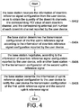
- Fig. 2 illustrates a system flowchart of a method for transmitting channel information in accordance with an exemplary embodiment of the disclosure.
- step S202 the base station 100 sends the downlink original reference signal x DL to the user device 102, so that the user device 102 receives the downlink reference signal y DL .
- step S204 the user device 102 performs a process of downlink channel detection and estimation according to the downlink reference signal y DL , so as to obtain the downlink channel estimation value h DL and information of downlink reference signal configuration .
- the information of downlink reference signal configuration specifies one or more base stations and antenna ports individually associated with one or more downlink channels that the user device 102 receives signals.
- the information of downlink reference signal configuration includes a quantity of the downlink channels, a corresponding physical cell identity (PCI) value of each of the downlink channels, and a corresponding antenna port of each of the downlink channels.
- PCI physical cell identity
- step S206 the user device 102 reports information of downlink reference signal configuration to the base station 100.
- the base station 100 determines the uplink reference signal configuration according to the information of downlink reference signal configuration, so as to generate the information of uplink reference signal configuration.
- the information of uplink reference signal configuration is primary configured to determine the transmission configuration of the user device 102 for transmitting the first uplink reference signal y UL_1 and the second uplink reference signal y UL_2 , such as determining which subframe numbers the first uplink reference signal y UL_1 and the second uplink reference signal y UL_2 start to be transmitted, and what subframe deployment is used in the transmission (e.g., which subframe's time slot is allocated for the transmission).
- the information of uplink reference signal configuration may include, for example, a value of the first uplink original reference signal x UL_1 and a value of the second uplink original reference signal x UL_2 .
- the base station 100 may negotiate with another base station for the transmission configuration of the user device 102 with respect to the second uplink reference signal y UL_2 according to the information of downlink reference signal configuration, so as to generate the information of uplink reference signal configuration.
- step S210 the base station 100 transmits the information of uplink reference signal configuration to the user device 102.
- step S212 the user device 102 generates the first uplink original reference signal x UL_1 according to the rule indicated by the information of uplink reference signal configuration.
- step S214 the user device 102 transmits the first uplink original reference signal x UL_1 to the base station 100, such that the base station 100 receives the first uplink reference signal y UL_1 .
- the base station 100 performs an uplink channel estimation process according to the first uplink reference signal y UL_1 .
- the base station 100 estimates the uplink channel noise n UL according to the first uplink reference signal y UL_1 , and calculates, based on the equation 4, the uplink channel estimation value h UL according to the first uplink reference signal y UL_1 , the known first uplink original reference signal x UL_1 and the uplink channel noise n UL .
- the user device 102 executes a signal pre-coding process.
- the user device 102 may generate the second uplink original reference signal x UL_2 according to the information of uplink reference signal configuration, and pre-code the second uplink original reference signal x UL_2 with the estimated downlink channel estimation value h DL to generate the encoded second uplink original reference signal x UL_2 '.
- the user device 102 replaces the elements of the pre-coding matrix p with the one or more downlink channel estimation values h DL , and then multiplies the pre-coding matrix p by the second uplink original reference signal x UL_2 to generate the encoded second uplink original reference signal x UL_2 '.
- step S220 the user device 102 transmits the encoded second uplink original reference signal x UL_2 ' to the base station 100, so that the base station 100 receives the second uplink reference signal y UL_2 .
- step S222 the base station decodes the second uplink reference signal y UL_2 through a downlink channel information decoding process, so as to obtain the downlink channel estimation value h DL carried by the second uplink reference signal y UL_2 .
- the base station 100 may calculate, based on the equation 6, the downlink channel estimation value h DL according to the second uplink reference signal y UL_2 , the known second uplink original reference signal x UL_2 ', the uplink channel noise n UL ' and the uplink channel estimation value h UL .
- steps S218 and S212 can be performed at the same time.
- step S218 can be performed before step S212.
- Fig. 3 illustrates a detailed flowchart of the process of downlink channel detection and estimation shown in step S204 of Fig. 2 .
- the user device 102 detects the PCI value and the corresponding antenna port number from the base station 100, so as to identify that the received signal is from which base station's which antenna.
- step S304 the user device 102 detects the downlink reference signal y DL from the base station 100 by using the PCI value and the corresponding antenna port number of the base station 100.
- step S306 the user device 102 detects the quantity of downlink channels of the corresponding antenna port according to the received downlink reference signal y DL .
- step S308 the user device 102 performs noise estimation on the downlink channel to obtain the downlink channel noise n DL .
- the user device 102 estimates the channel status of the downlink channel to obtain the downlink channel estimation value h DL .
- the user device 102 may, based on the equation 2, subtract the value of the downlink channel noise n DL from the value of the downlink reference signal y DL , and then divide the result by the value of the downlink original reference signal x DL , so as to obtain the downlink channel estimation value h DL .
- step S312 the user device 102 reports the base station 100 the quantity of the downlink channels, the corresponding PCI value and the corresponding antenna port number (information of downlink reference signal configuration) obtained from the base station 100.
- Fig. 4 illustrates an example of a detailed flowchart of the determination of the uplink reference signal configuration shown in step S208 of Fig. 2 .
- step S402 the base station 100 receives the information of downlink reference signal configuration from the user device 102, so as to obtain the quantity of the downlink channels, the corresponding PCI value of each downlink channel, and the corresponding antennal port number of each downlink channel reported by the user device 102.
- step S404 the base station 100 determines the transmission configuration of the first uplink reference signal y UL_1 according to the information of downlink reference signal configuration reported by the user device 102, such as determining which subframe number the transmission is initiated and what subframe deployment is used in the transmission.
- step S406 the base station 100 negotiates, according to the information of downlink reference signal configuration reported by the user device 102, with another base station for the transmission configuration of the second uplink reference signal y UL_2 . Therefore, signal collision among user devices that occurs when the user device 102 transmits the second uplink reference signal y UL_2 can be avoided.
- step S408 the base station 100 transmits the information of uplink reference signal configuration to the user device 102 to notify the user device 102 the transmission configuration of the first uplink reference signal y UL_1 and the second uplink reference signal y UL_2 .
- Fig. 5 illustrates an example of a detailed flowchart of the uplink channel estimation process shown in step S216 of Fig. 2 .
- step S502 the base station 100 estimates noises on the uplink channel according to the first uplink reference signal y UL, so as to obtain the uplink channel noise n UL .
- the base station 100 estimates the uplink channel to obtain the corresponding uplink channel estimation value h UL .
- the base station 100 may calculate the uplink channel estimation value h UL based on the equation 4. That is, the base station 100 may subtract the value of the uplink channel noise n UL from the value of the received first uplink reference signal y UL_1 , and then divide the result by the value of the first uplink original reference signal x UL_1 to obtain the uplink channel estimation value h UL .
- Fig. 6 illustrates an example of a detailed flowchart of the signal pre-decoding process shown in step S218 of Fig. 2 .
- step S602 the user device 102 sets the matrix element of the pre-coding matrix p as the estimated downlink channel estimation value h DL .
- step S604 the user device 102 generates the second uplink original reference signal x UL_2 according to the rule indicated by the information of uplink reference signal configuration.
- step S606 the user device 102 generates the encoded second uplink original reference signal x UL_2 ' according to the pre-coding matrix p and the second uplink original reference signal x UL_2 . For example, the user device 102 multiplies the value of the matrix element of the pre-coding matrix p by the value of the second uplink original reference signal x UL_2 to obtain the encoded second uplink original reference signal x UL_2 '.
- step S608 the user device 102 reports the base station 100 the encoded second uplink original reference signal x UL_2 ', which is received as the second uplink reference signal y UL_2 at the base station 100.
- Fig. 7 illustrates an example of a detailed flowchart of the downlink channel information decoding process shown in step S222 of Fig. 2 .
- step S702 the base station 100 estimates noises on the uplink channel according to the second uplink reference signal y UL_2 , so as to obtain the uplink channel noise n UL '.
- step S704 the base station 100 calculates, based on the equation 6, the downlink channel estimation value h DL by subtracting the value of the uplink channel noise n UL from the value of the second uplink reference signal y UL_2 , and then dividing the result by a multiplication result of the uplink channel estimation value h UL and the value of the second uplink original reference signal x UL_2 .
- Figs. 8-11 schematically illustrate different stages of the method for transmitting channel information in accordance with an exemplary embodiment of the disclosure.
- the wireless communication system 80 includes a first base station 800A, a second base station 800B, a first user device 802A and a second user device 802B.
- the first and second user devices 802A, 802B locate in a common signal coverage area provided by the first and second base stations 800A, 800B, wherein the first user device 802A is served by the first base station 800A and not by the second user device 802B, while the second user device 802B is served by the second base station 800B and not by the first user device 802A.
- the first base station 800A includes two antennas A1, A2.
- the second base station 800B includes two antennas B1, B2.
- Each of the first and second user devices 802A, 802B includes one antenna.
- the first and second user devices 802A, 802B may receive the PCI values of the first and second base stations 800A, 800B (e.g., the PCI value of the first base station 800A is PCI_A, and the PCI value of the second base station 800B is PCI_B), and receive the downlink reference signals and the quantity of the downlink channels form each antenna of the first and second base stations 800A, 800B.
- the PCI values of the first and second base stations 800A, 800B e.g., the PCI value of the first base station 800A is PCI_A, and the PCI value of the second base station 800B is PCI_B
- a parameter in formula is denoted with a superscript and a subscript
- the superscript represents the signal sending terminal corresponding to the parameter
- the subscript represents the signal receiving terminal corresponding to the parameter.
- the downlink reference signal received by the first user device 802 A can be expressed as: y 802 A 800 A , A 1 y 802 A 800 A , A 2 y 802 A 800 B , B 1 y 802 A 800 B , B 2
- y 802 A 800 A A 1 represents the downlink reference signal that the first user device 802A receives from the antenna A1 of the first base station 800A
- y 802 A 800 A A 2 represents the downlink reference signal that the first user device 802A receives from the antenna A2 of the first base station 800A
- y 802 A 800 B , B 1 represents the downlink reference signal that the first user device 802A receives from the antenna B1 of the second base station 800B
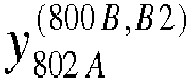
- y 802 A 800 B , B 2 represents the downlink reference signal that the first user device 802A receives from the antenna B2 of the second base station 800B.
- the downlink reference signals y 802 A 800 A , A 1 , y 802 A 800 A , A 2 , y 802 A 800 B , B 1 and y 802 A 800 B , B 2 are transmitted respectively through the time-frequency resources 81, 82, 83 and 84.
- Each block depicted in the figure represents a unit of the time-frequency resources.
- the downlink channel noises that individually corresponding to the downlink reference signals y 802 A 800 A , A 1 y 802 A 800 A , A 2 y 802 A 800 B , B 1 y 802 A 800 B , B 2 can be expressed as: n 802 A 800 A , A 1 n 802 A 800 A , A 2 n 802 A 800 B , B 1 n 802 A 800 B , B 2
- the downlink original reference signals that individually corresponding to the downlink reference signals y 802 A 800 A , A 1 y 802 A 800 A , A 2 y 802 A 800 B , B 1 y 802 A 800 B , B 2 can be expressed as: x 802 A 800 A , A 1 x 802 A 800 A , A 2 x 802 A 800 B , B 1 x 802 A 800 B , B 2
- the first and second user devices 802A, 802B respectively report the quantity, the corresponding PCI value and the corresponding antenna port of the downlink channels (information of downlink reference signal configuration) to the corresponding base stations.
- DLC 802A PCI_A 802 A 800 A , A 1 PCI_A 802 A 800 A , A 2 PCI_B 802 A 800 B , B 1 PCI_B 802 A 800 B , B 2
- PCI_A 802 A 800 A A 1 represents the PCI value corresponding to the downlink channel from the antenna A1 of the first base station 800A to the first user device 802A
- PCI_B 802 A 800 B B 1 represents the PCI value corresponding to the downlink channel from the antenna B1 of the second base station 800B to the first user device 802A
- PCI_A 802 A 800 A , A 2 represents the PCI value corresponding to the downlink channel from the antenna A2 of the first base station 800A to the first user device 802A
- DLC 802 B PCI_A 802 B 800 A , A 1 PCI_A 802 B 800 A , A 2 PCI_B 802 B 800 B , B 1 PCI_B 802 B 800 B , B 2
- PCI_A 802 B 800 A A 1 represents the PCI value corresponding to the downlink channel from the antenna A1 of the first base station 800A to the second user device 802B
- PCI_B 802 B 800 B B 1 represents the PCI value corresponding to the downlink channel from the antenna B1 of the second base station 800B to the second user device 802B
- PCI_A 802 B 800 A , A 2 represents the PCI value corresponding to the downlink channel from the antenna A2 of the first base station 800A to the second user device 802B
- PCI_B 802 B 800 B , B 2 represents the PCI value corresponding to the downlink channel from the antenna A2 of the first base station 800A to the second user device 802B
- the first and second base stations 800A, 800B negotiate with each other for the transmission configuration of the first and second user devices 802A, 802B that transmit the second uplink reference signals, respectively.
- the transmission configuration ULC2 802A is a transmission configuration that the first user device 802A uses to report the reference signals.
- the transmission configuration ULC2 802B is a transmission configuration that the second user device 802B uses to report the reference signals.
- the first and second base stations 800A, 800B may communication the transmission configurations ULC2 802A , ULC2 802B with each other to coordinate the transmissions of the first and second user devices 802A, 802B, such as determining which subframe numbers the first and second user devices 802A, 802B can start to transmit the second uplink reference signals, and what subframe deployment is used in the transmission.
- the first base station 800A then notifies the first user device 802A the transmission configuration ULC1 802A of the corresponding first uplink reference signal and the transmission configuration ULC2 802A of the corresponding second uplink reference signal. Also, the second base station 800B notifies the second user device 802B the transmission configuration ULC1 802B of the corresponding first uplink reference signal and the transmission configuration ULC2 802B of the corresponding second uplink reference signal.
- the transmission configuration ULC1 802A refers to a transmission configuration that the first user device 802A used to report the first uplink reference signal
- the transmission configuration ULC1 802B refers to a transmission configuration that the second user device 802B used to report the first uplink reference signal.
- the first user device 802A may multiply the pre-coding matrix P 802A by the second uplink original reference signal to generate the corresponding encoded second uplink original reference signal.
- the second user device 802B may multiply the pre-coding matrix p 802B by the second uplink original reference signal to generate the corresponding encoded second uplink original reference signal.
- the first user device 802A transmits the first uplink original reference signal and the encoded second uplink original reference signal. Because the first user device 802A locates in the common signal coverage area of the first and second base stations 800A, 800B, the first uplink original reference signal and the encoded second uplink original reference signal transmitted by the first user device 802A can be sent to both the first and second base stations 800A, 800B. In other words, both the first and second base stations 800A, 800B may receive the first uplink reference signal and the second uplink reference signal from the first user device 802A.
- first uplink original reference signal and the encoded second uplink original reference signal transmitted by the second user device 802B are received as the first uplink reference signal and the second uplink reference signal at both the first and second base stations 800A, 800B.
- the first and second uplink reference signals from the first user device 802A are corresponding to the time-frequency resources 1111 and 1112, respectively; and the first and second uplink reference signals from the second user device 802B are corresponding to the time-frequency resources 1113 and 1114, respectively.
- the first and second base stations 800A, 800B can obtain the uplink channel estimation values for the uplink channels from each user device to each antenna.
- the second uplink reference signal y 2 800 A , A 1 802 A ⁇ is represented as a function that varies with a carried downlink channel estimation value.
- the second uplink reference signal y 2 800 A , A 1 802 A h 802 A 800 A , A 1 refers to a second uplink reference signal that carries the downlink channel estimation value h 802 A 800 A , A 1 , and is transmitted from the first user device 802A to the antenna A1 of the first base station 800A.
- h 800 A A 1 802 A represents the uplink channel estimation value for the uplink channel from the first user device 802A to the antenna A1 of the first base station 800A; x 2 800 A 802 A represents the second uplink original reference signal for the uplink channel from the first user device 802A to the first base station 800A; n 800 A , A 1 802 A represents the uplink channel noise; and h 802 A 800 A , A 1 , h 802 A 800 A , A 2 , h 802 A 800 B , B 1 and h 802 A 800 B , B 2 represent the four downlink channel estimation values measured by the first user device 802A.
- the first base station 800A receives the first uplink reference signal and the second uplink reference signal from the second user device 802B. Therefore, the first base station 800A can obtain the corresponding uplink channel estimation value according to the first uplink reference signal of the second user device 802B, and obtain the downlink channel estimation value measured by the second user device 802B according to the obtained uplink channel estimation value and the second uplink reference signal of the second user device 802B.
- the first base station 800A may transmit the it to the base station serving the second user device 802B, e.g., the second base station 800B.
- the user device may report, as instructed by the base station, a particular uplink reference signal carrying a downlink channel estimation value to the base station, so that the base station can use this reference signal to decode the downlink channel information.
- the information carried by the particular uplink reference signal that the user device reports to the base station is not limited to the downlink channel estimation value. It can also be the associated information of the downlink channel estimation value, such as a difference (downlink channel variation value) between a previously measured downlink channel estimation value (previous downlink channel estimation value) and a currently measured downlink channel estimation value.
- the base station first decodes the difference between two consecutively obtained channel estimation values, and then performs compensation computation on the difference to obtain the current downlink channel estimation value. In this manner, even if the uplink channel and the downlink channel are not symmetrical during the transmission, the base station can still effectively obtain the status information of the downlink channel. Therefore, the base station performs a proper pre-coding process on the downlink signal, so as to eliminate the influence of the channel effect on the signal, thereby improving the overall transmission quality of the wireless mobile communication networks.
Landscapes
- Engineering & Computer Science (AREA)
- Signal Processing (AREA)
- Computer Networks & Wireless Communication (AREA)
- Power Engineering (AREA)
- Quality & Reliability (AREA)
- Physics & Mathematics (AREA)
- Electromagnetism (AREA)
- Mobile Radio Communication Systems (AREA)
Abstract
A method for transmitting channel information, adapted to a base station, includes: receiving a first uplink reference signal and a second uplink reference signal from a user device, obtaining an uplink channel estimation value according to the first uplink reference signal, and obtaining a downlink channel estimation value according to the second uplink reference signal and the uplink channel estimation value.
Description
- The disclosure relates to methods for transmitting channel information and wireless communication systems using the same.
- As the demand for tranceiving data through wireless mobile communication networks grows rapidly, telecom operators begin to study how to achieve higher throughput and more stable Qos in a limited bandwidth.
- To enhance the performance of wireless mobile communication systems, widen the bandwidth and improve the spectrum efficiency, the telecom operators may employ, in addition to deploying large base stations and increasing low-cost small base stations, multi-antenna techniques such as massive multi-input multi-output (MIMO) and distributed MIMO to meet the required transmission speed and service quality.
- However, the performance of the multi-antenna techniques depends on how the base station acquires the downlink channel information correctly, such that the base station may use it to form constructive synthetic waves, instead of destructive synthetic waves, towards the reception apparatus such as user devices.
- Therefore, there is a need to provide methods for transmitting channel information and wireless communication systems using the same, so as to effectively report the base station the downlink channel information.
- The present disclosure relates to methods for transmitting channel information and wireless communication systems using the same. According to the embodiments of the present disclosure, the user device may report, as instructed by the base station, a particular uplink reference signal that carries a downlink channel estimation value to the base station, so that the downlink channel information can be decoded by the base station.
- According to one of the exemplary embodiments of the disclosure, a method, adapted to a base station, for transmitting channel information is provided. The method includes the following steps: a first uplink reference signal and a second uplink reference signal are received from a user device; an uplink channel estimation value is obtained according to the first uplink reference signal; and a downlink channel estimation value is obtained according to the second uplink reference signal and the uplink channel estimation value.
- According to one of the exemplary embodiments of the disclosure, a method, adapted to a user device, for transmitting channel information is provided. The method includes the following steps: in response to information of uplink reference signal configuration from a base station, a first uplink original reference signal and a second uplink original reference signal are generated; a encoded second uplink original reference signal is generated by pre-coding the second uplink original reference signal with a downlink channel estimation value or a downlink channel variation value, the downlink channel variation value being a difference value between the downlink channel estimation value and a previous downlink channel estimation value; and the first uplink original reference signal and the encoded second uplink original reference signal are transmitted back to the base station.
- A wireless communication system includes a first base station and a first user device. The first base station is configured to: receive a first uplink reference signal and a second uplink reference signal; obtain an uplink channel estimation value according to the first uplink reference signal; and obtain a downlink channel estimation value according to the uplink channel estimation value and the second uplink reference signal. The first user device is configured to: in response to information of uplink reference signal configuration from the first base station, generate a first uplink original reference signal and a second uplink original reference signal; pre-code the second uplink original reference signal with the downlink channel estimation value or a downlink channel variation value to generate a encoded second uplink original reference signal, the encoded second uplink original reference signal being a difference value between the downlink channel estimation value and a previous downlink channel estimation value; transmit the first uplink original reference signal so that the first base station receives the first uplink reference signal; and transmit the encoded second uplink original reference signal so that the first base station receives the second uplink reference signal.
- The foregoing will become better understood with regard to the following detailed description of the preferred but non-limiting embodiment(s). The following description is made with reference to the accompanying drawings.
-
-
Fig. 1 illustrates a schematic diagram of a wireless communication system in accordance with an exemplary embodiment of the disclosure. -
Fig. 2 illustrates a system flowchart of a method for transmitting channel information in accordance with an exemplary embodiment of the disclosure. -
Fig. 3 illustrates a detailed flowchart of the process of downlink channel detection and estimation shown inFig. 2 . -
Fig. 4 illustrates a detailed flowchart of the determination of the uplink reference signal configuration shown inFig. 2 . -
Fig. 5 illustrates a detailed flowchart of the uplink channel estimation process shown inFig. 2 . -
Fig. 6 illustrates a detailed flowchart of the signal pre-decoding process shown inFig. 2 . -
Fig. 7 illustrates a detailed flowchart of the downlink channel information decoding process shown inFig. 2 . -
Figs. 8-11 schematically illustrate different stages of the method for transmitting channel information in accordance with an exemplary embodiment of the disclosure. - A number of exemplary embodiments will be described below in detail. However, the exemplary embodiments of the disclosure are for detailed descriptions only, not for limiting the scope of protection of the invention.
-
Fig. 1 illustrates a schematic diagram of awireless communication system 10 in accordance with an exemplary embodiment of the disclosure. Thewireless communication system 10 includes abase station 100 and auser device 102. Although only onebase station 100 and only oneuser device 102 are shown inFig. 1 , this is just for the ease of illustration, and actually, thewireless communication system 10 may include one ormore base stations 100 and one ormore user devices 102. - The physical transmission channel from the
base station 100 to theuser device 102 refers to a downlink channel, while the physical transmission channel from theuser device 102 to thebase station 100 refers to an uplink channel. Generally, if thewireless communication system 10 adopts time division duplexing (TDD), thebase station 100 can precisely convert the measured uplink channel status into the downlink channel status based on the feature of channel reciprocity because both the downlink channel and the uplink channel use the same frequency bands during the transmission of thebase station 100 and theuser device 102. - However, if the
wireless communication system 10 adopts frequency division duplexing (FDD), the downlink channel and the uplink channel use different frequency bands during the transmission of thebase station 100 and theuser device 102. Accordingly, thebase station 100 cannot directly convert the measured uplink channel status into the downlink channel status by using the feature of channel reciprocity. - To address this issue, according to the exemplary embodiments of the disclosure, the
user device 102 may report, as instructed by thebase station 100, a particular uplink reference signal carrying a downlink channel estimation value to thebase station 100, so that the downlink channel information can be decoded by thebase station 100. - As shown in
Fig. 1 , first, thebase station 100 transmits a downlink original reference signal xDL to theuser device 102, such that theuser device 102 receives a downlink reference signal yDL. Because a transmitted signal will be influenced by the channel and the noises, the downlink reference signal yDL can be expressed as follows:
- In an aspect, the downlink original reference signal xDL is deemed as a downlink reference signal yDL that has not been influenced by the channel and the noises, or an original value of the downlink reference signal yDL.
- The
base station 100 may communicate the value of the downlink original reference signal xDL with theuser device 102 in advance. Therefore, for theuser device 102, the value of the downlink original reference signal xDL is known. In such cases, theuser device 102 may use the following equation to obtain the downlink channel estimation value hDL:
- The
user device 102 may further generate, as instructed by thebase station 100, the first uplink original reference signal xUL_1 and the second uplink original reference signal xUL_2. The first uplink original reference signal xUL_1 can be any reference signal provided to thebase station 100 for measuring the uplink channel status, which is sent by theuser device 102 and received as the first uplink reference signal yUL_1 at thebase station 100. The first uplink reference signal yUL_1 can be expressed as follows:
where hUL represents the uplink channel estimation value; xUL_1 represents the first uplink original reference signal; nUL represents the uplink channel noise measured with the first uplink reference signal yUL_1. - In an aspect, the first uplink original reference signal xUL_1 is deemed as a first uplink reference signal yUL_1 that has not been influenced by the channel and the noises, or an original value of the first uplink reference signal yUL_1.
- For the
base station 100, the value of the first uplink original reference signal xUL_1 is known, and the uplink channel noise nUL can be obtained through a noise estimation process. Therefore, thebase station 100 may use the following equation to obtain the uplink channel estimation value hUL:
- In another aspect, the
user device 102 may utilize the second uplink original reference signal xUL_2 to carry the measured downlink channel estimation value hDL, so that the measured downlink channel estimation value hDL can be brought to thebase station 100. For example, theuser device 102 may convert the downlink channel estimation value hDL into matrix elements of a pre-coding matrix p, and then multiply the pre-coding matrix p by the second uplink original reference signal xUL_2 to generate the encoded second uplink original reference signal xUL_2'. The encoded second uplink original reference signal xUL_2' is sent by theuser device 102 and received as the second uplink reference signal yUL_2 at thebase station 100. The second uplink reference signal yUL_2 can be expressed as follows:
where nUL' represents the uplink channel noise measured with the second uplink reference signal yUL_2. - In an aspect, the encoded second uplink original reference signal xUL_2' is deemed as a second uplink reference signal yUL_2 that has not been influenced by the channel and the noises, or an original value of the second uplink reference signal yUL_2.
- For the
base station 100, the value of the second uplink original reference signal xUL_2 is known, nUL' can be obtained through a noise estimation process, and the uplink channel estimation value hUL can be obtained through the first uplink reference signal yUL_1. Therefore, thebase station 100 may use the following equation to obtain the downlink channel estimation value hDL:
- Simply to say, the
base station 100 first receives the first uplink reference signal yUL_1 and the second uplink reference signal yUL_2 from theuser device 102, then obtains the uplink channel estimation value hUL according to the first uplink reference signal yUL_1, and obtains the downlink channel estimation value hDL according to the uplink channel estimation value hUL, the second uplink reference signal yUL_2 and the second uplink original reference signal xUL_2. - In the manner described above, no matter whether the uplink channel and the downlink channel are symmetrical (e.g., using the same frequency bands), the
base station 100 can still obtain the downlink channel information (downlink channel estimation value hDL) correctly and effectively. -
Fig. 2 illustrates a system flowchart of a method for transmitting channel information in accordance with an exemplary embodiment of the disclosure. - In step S202, the
base station 100 sends the downlink original reference signal xDL to theuser device 102, so that theuser device 102 receives the downlink reference signal yDL. - In step S204, the
user device 102 performs a process of downlink channel detection and estimation according to the downlink reference signal yDL, so as to obtain the downlink channel estimation value hDL and information of downlink reference signal configuration . - The information of downlink reference signal configuration specifies one or more base stations and antenna ports individually associated with one or more downlink channels that the
user device 102 receives signals. In an exemplary embodiment, the information of downlink reference signal configuration includes a quantity of the downlink channels, a corresponding physical cell identity (PCI) value of each of the downlink channels, and a corresponding antenna port of each of the downlink channels. - In step S206, the
user device 102 reports information of downlink reference signal configuration to thebase station 100. - In step S208, the
base station 100 determines the uplink reference signal configuration according to the information of downlink reference signal configuration, so as to generate the information of uplink reference signal configuration. The information of uplink reference signal configuration is primary configured to determine the transmission configuration of theuser device 102 for transmitting the first uplink reference signal yUL_1 and the second uplink reference signal yUL_2, such as determining which subframe numbers the first uplink reference signal yUL_1 and the second uplink reference signal yUL_2 start to be transmitted, and what subframe deployment is used in the transmission (e.g., which subframe's time slot is allocated for the transmission). Thus, signal collision amongdifferent user devices 102 can be avoided. The information of uplink reference signal configuration may include, for example, a value of the first uplink original reference signal xUL_1 and a value of the second uplink original reference signal xUL_2. - In an exemplary embodiment, the
base station 100 may negotiate with another base station for the transmission configuration of theuser device 102 with respect to the second uplink reference signal yUL_2 according to the information of downlink reference signal configuration, so as to generate the information of uplink reference signal configuration. - In step S210, the
base station 100 transmits the information of uplink reference signal configuration to theuser device 102. - In step S212, the
user device 102 generates the first uplink original reference signal xUL_1 according to the rule indicated by the information of uplink reference signal configuration. - In step S214, the
user device 102 transmits the first uplink original reference signal xUL_1 to thebase station 100, such that thebase station 100 receives the first uplink reference signal yUL_1. - In step S216, the
base station 100 performs an uplink channel estimation process according to the first uplink reference signal yUL_1. For example, thebase station 100 estimates the uplink channel noise nUL according to the first uplink reference signal yUL_1, and calculates, based on the equation 4, the uplink channel estimation value hUL according to the first uplink reference signal yUL_1, the known first uplink original reference signal xUL_1 and the uplink channel noise nUL. - In step S218, the
user device 102 executes a signal pre-coding process. Theuser device 102 may generate the second uplink original reference signal xUL_2 according to the information of uplink reference signal configuration, and pre-code the second uplink original reference signal xUL_2 with the estimated downlink channel estimation value hDL to generate the encoded second uplink original reference signal xUL_2'. - For example, the
user device 102 replaces the elements of the pre-coding matrix p with the one or more downlink channel estimation values hDL, and then multiplies the pre-coding matrix p by the second uplink original reference signal xUL_2 to generate the encoded second uplink original reference signal xUL_2'. - In step S220, the
user device 102 transmits the encoded second uplink original reference signal xUL_2' to thebase station 100, so that thebase station 100 receives the second uplink reference signal yUL_2. - In step S222, the base station decodes the second uplink reference signal yUL_2 through a downlink channel information decoding process, so as to obtain the downlink channel estimation value hDL carried by the second uplink reference signal yUL_2.
- For example, the
base station 100 may calculate, based on the equation 6, the downlink channel estimation value hDL according to the second uplink reference signal yUL_2, the known second uplink original reference signal xUL_2', the uplink channel noise nUL' and the uplink channel estimation value hUL. - It is noted that the method for transmitting channel information in accordance with the exemplary embodiments of the disclosure is not required to be performed in the particular order shown in
Fig. 2 . For example, steps S218 and S212 can be performed at the same time. Alternatively, step S218 can be performed before step S212. -
Fig. 3 illustrates a detailed flowchart of the process of downlink channel detection and estimation shown in step S204 ofFig. 2 . - At step S302, the
user device 102 detects the PCI value and the corresponding antenna port number from thebase station 100, so as to identify that the received signal is from which base station's which antenna. - In step S304, the
user device 102 detects the downlink reference signal yDL from thebase station 100 by using the PCI value and the corresponding antenna port number of thebase station 100. - In step S306, the
user device 102 detects the quantity of downlink channels of the corresponding antenna port according to the received downlink reference signal yDL. - In step S308, the
user device 102 performs noise estimation on the downlink channel to obtain the downlink channel noise nDL. - In step S310, the
user device 102 estimates the channel status of the downlink channel to obtain the downlink channel estimation value hDL. For example, theuser device 102 may, based on theequation 2, subtract the value of the downlink channel noise nDL from the value of the downlink reference signal yDL, and then divide the result by the value of the downlink original reference signal xDL, so as to obtain the downlink channel estimation value hDL. - In step S312, the
user device 102 reports thebase station 100 the quantity of the downlink channels, the corresponding PCI value and the corresponding antenna port number (information of downlink reference signal configuration) obtained from thebase station 100. -
Fig. 4 illustrates an example of a detailed flowchart of the determination of the uplink reference signal configuration shown in step S208 ofFig. 2 . - In step S402, the
base station 100 receives the information of downlink reference signal configuration from theuser device 102, so as to obtain the quantity of the downlink channels, the corresponding PCI value of each downlink channel, and the corresponding antennal port number of each downlink channel reported by theuser device 102. - In step S404, the
base station 100 determines the transmission configuration of the first uplink reference signal yUL_1 according to the information of downlink reference signal configuration reported by theuser device 102, such as determining which subframe number the transmission is initiated and what subframe deployment is used in the transmission. - In step S406, the
base station 100 negotiates, according to the information of downlink reference signal configuration reported by theuser device 102, with another base station for the transmission configuration of the second uplink reference signal yUL_2. Therefore, signal collision among user devices that occurs when theuser device 102 transmits the second uplink reference signal yUL_2 can be avoided. - In step S408, the
base station 100 transmits the information of uplink reference signal configuration to theuser device 102 to notify theuser device 102 the transmission configuration of the first uplink reference signal yUL_1 and the second uplink reference signal yUL_2. -
Fig. 5 illustrates an example of a detailed flowchart of the uplink channel estimation process shown in step S216 ofFig. 2 . - In step S502, the
base station 100 estimates noises on the uplink channel according to the first uplink reference signal yUL, so as to obtain the uplink channel noise nUL. - In step S504, the
base station 100 estimates the uplink channel to obtain the corresponding uplink channel estimation value hUL. For example, thebase station 100 may calculate the uplink channel estimation value hUL based on the equation 4. That is, thebase station 100 may subtract the value of the uplink channel noise nUL from the value of the received first uplink reference signal yUL_1, and then divide the result by the value of the first uplink original reference signal xUL_1 to obtain the uplink channel estimation value hUL. -
Fig. 6 illustrates an example of a detailed flowchart of the signal pre-decoding process shown in step S218 ofFig. 2 . - In step S602, the
user device 102 sets the matrix element of the pre-coding matrix p as the estimated downlink channel estimation value hDL. - In step S604, the
user device 102 generates the second uplink original reference signal xUL_2 according to the rule indicated by the information of uplink reference signal configuration. - In step S606, the
user device 102 generates the encoded second uplink original reference signal xUL_2' according to the pre-coding matrix p and the second uplink original reference signal xUL_2. For example, theuser device 102 multiplies the value of the matrix element of the pre-coding matrix p by the value of the second uplink original reference signal xUL_2 to obtain the encoded second uplink original reference signal xUL_2'. - In step S608, the
user device 102 reports thebase station 100 the encoded second uplink original reference signal xUL_2', which is received as the second uplink reference signal yUL_2 at thebase station 100. -
Fig. 7 illustrates an example of a detailed flowchart of the downlink channel information decoding process shown in step S222 ofFig. 2 . - In step S702, the
base station 100 estimates noises on the uplink channel according to the second uplink reference signal yUL_2, so as to obtain the uplink channel noise nUL'. - In step S704, the
base station 100 calculates, based on the equation 6, the downlink channel estimation value hDL by subtracting the value of the uplink channel noise nUL from the value of the second uplink reference signal yUL_2, and then dividing the result by a multiplication result of the uplink channel estimation value hUL and the value of the second uplink original reference signal xUL_2. -
Figs. 8-11 schematically illustrate different stages of the method for transmitting channel information in accordance with an exemplary embodiment of the disclosure. - Please refer to
Fig. 8 . Thewireless communication system 80 includes afirst base station 800A, asecond base station 800B, afirst user device 802A and asecond user device 802B. In this example, the first andsecond user devices second base stations first user device 802A is served by thefirst base station 800A and not by thesecond user device 802B, while thesecond user device 802B is served by thesecond base station 800B and not by thefirst user device 802A. - The
first base station 800A includes two antennas A1, A2. Thesecond base station 800B includes two antennas B1, B2. Each of the first andsecond user devices - The first and
second user devices second base stations first base station 800A is PCI_A, and the PCI value of thesecond base station 800B is PCI_B), and receive the downlink reference signals and the quantity of the downlink channels form each antenna of the first andsecond base stations - In the examples of
Figs. 8-11 , if a parameter in formula is denoted with a superscript and a subscript, the superscript represents the signal sending terminal corresponding to the parameter, and the subscript represents the signal receiving terminal corresponding to the parameter. - Taking the
first user device 802 A as an example, the downlink reference signal received by thefirst user device 802 A can be expressed as:
where
first user device 802A receives from the antenna A1 of thefirst base station 800A;
first user device 802A receives from the antenna A2 of thefirst base station 800A;
first user device 802A receives from the antenna B1 of thesecond base station 800B;
first user device 802A receives from the antenna B2 of thesecond base station 800B. - In the example of
Fig. 8 , the downlinkreference signals 


frequency resources - The downlink channel noises that individually corresponding to the downlink
reference signals 

- The downlink original reference signals that individually corresponding to the downlink
reference signals 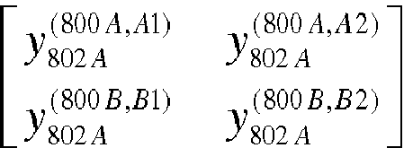

- Based on the equations 4 and 7-9, four downlink channel estimation values for the downlink channels between the
first user device 802A and the antennas A1, A2, B1, B2 of thebase stations 
where
first base station 800A to thefirst user device 802A;
first base station 800A to thefirst user device 802A;
second base station 800B to thefirst user device 802A;
second base station 800B to thefirst user device 802A. - Next, please refer to
Fig. 9 . The first andsecond user devices - As shown in
Fig. 9 , the information of downlink reference signal configuration, DLC802A, that thefirst user device 802A reports to thefirst base station 800A can be expressed as:
where
first base station 800A to thefirst user device 802A;
second base station 800B to thefirst user device 802A;
first base station 800A to thefirst user device 802A;
second base station 800B to thefirst user device 802A. - The information of downlink reference signal configuration DLC802B that the
second user device 802B reports to thesecond base station 800B can be expressed as:
where
first base station 800A to thesecond user device 802B;
second base station 800B to thesecond user device 802B;
first base station 800A to thesecond user device 802B;
second base station 800B to thesecond user device 802B. - Next, please refer to
Fig. 10 . The first andsecond base stations second user devices Fig. 10 , the transmission configuration ULC2802A is a transmission configuration that thefirst user device 802A uses to report the reference signals. The transmission configuration ULC2802B is a transmission configuration that thesecond user device 802B uses to report the reference signals. In order to avoid signal collision or interference when sending signals, the first andsecond base stations second user devices second user devices - The
first base station 800A then notifies thefirst user device 802A the transmission configuration ULC1802A of the corresponding first uplink reference signal and the transmission configuration ULC2802A of the corresponding second uplink reference signal. Also, thesecond base station 800B notifies thesecond user device 802B the transmission configuration ULC1802B of the corresponding first uplink reference signal and the transmission configuration ULC2802B of the corresponding second uplink reference signal. Here, the transmission configuration ULC1802A refers to a transmission configuration that thefirst user device 802A used to report the first uplink reference signal, and the transmission configuration ULC1802B refers to a transmission configuration that thesecond user device 802B used to report the first uplink reference signal. - Next, please refer to
Fig. 11 . Thefirst user device 802A sets the values of the matrix elements of the pre-coding matrix as the four obtained downlink channelestimation values 


- Likewise, the
second user device 802B may generate the pre-coding matrix p802B as follows:
where
first base station 800A to thesecond user device 802B;
first base station 800A to thesecond user device 802B;
second base station 800B to thesecond user device 802B;
second base station 800B to thesecond user device 802B. - The
first user device 802A may multiply the pre-coding matrix P802A by the second uplink original reference signal to generate the corresponding encoded second uplink original reference signal. Thesecond user device 802B may multiply the pre-coding matrix p802B by the second uplink original reference signal to generate the corresponding encoded second uplink original reference signal. - Then, the
first user device 802A transmits the first uplink original reference signal and the encoded second uplink original reference signal. Because thefirst user device 802A locates in the common signal coverage area of the first andsecond base stations first user device 802A can be sent to both the first andsecond base stations second base stations first user device 802A. - Likewise, the first uplink original reference signal and the encoded second uplink original reference signal transmitted by the
second user device 802B are received as the first uplink reference signal and the second uplink reference signal at both the first andsecond base stations - As shown in
Fig. 11 , the first and second uplink reference signals from thefirst user device 802A are corresponding to the time-frequency resources second user device 802B are corresponding to the time-frequency resources - The
first base station 800A may calculate, according to the first uplink reference signal that the antenna A1 receives from the first user device 802, the uplink channelestimation value 


first base station 800A;
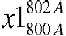
reference signal 
- Based on the same mechanism, the first and
second base stations - On the other hand, the second uplink reference signal,

first base station 800A receives from thefirst user device 802A can be expressed as follows:
- Here, the second uplink
reference signal 
reference signal 
estimation value 
first user device 802A to the antenna A1 of thefirst base station 800A. - In equation 16,

first user device 802A to the antenna A1 of thefirst base station 800A;
first user device 802A to thefirst base station 800A;


first user device 802A. - Then, the
first base station 800A decodes the matrix elements presented in the pre-coding matrix p802A for obtaining the downlink channel estimation values measured by thefirst user device 802A:
- The
first base station 800A may also decode the matrix elements presented in the pre-coding matrix p802B for obtaining the downlink channel estimation values measured by thesecond user device 802B:
- In the manner described above, although the
second user device 802B is not served by thefirst base station 800A, thefirst base station 800A receives the first uplink reference signal and the second uplink reference signal from thesecond user device 802B. Therefore, thefirst base station 800A can obtain the corresponding uplink channel estimation value according to the first uplink reference signal of thesecond user device 802B, and obtain the downlink channel estimation value measured by thesecond user device 802B according to the obtained uplink channel estimation value and the second uplink reference signal of thesecond user device 802B. - In an exemplary embodiment, after obtaining the downlink channel estimation value measured by the
second user device 802B, thefirst base station 800A may transmit the it to the base station serving thesecond user device 802B, e.g., thesecond base station 800B. - Based on the above, methods for transmitting channel information and wireless communication systems using the same are provided. According to the exemplary embodiments of the disclosure, the user device may report, as instructed by the base station, a particular uplink reference signal carrying a downlink channel estimation value to the base station, so that the base station can use this reference signal to decode the downlink channel information. The information carried by the particular uplink reference signal that the user device reports to the base station is not limited to the downlink channel estimation value. It can also be the associated information of the downlink channel estimation value, such as a difference (downlink channel variation value) between a previously measured downlink channel estimation value (previous downlink channel estimation value) and a currently measured downlink channel estimation value. In such cases, the base station first decodes the difference between two consecutively obtained channel estimation values, and then performs compensation computation on the difference to obtain the current downlink channel estimation value. In this manner, even if the uplink channel and the downlink channel are not symmetrical during the transmission, the base station can still effectively obtain the status information of the downlink channel. Therefore, the base station performs a proper pre-coding process on the downlink signal, so as to eliminate the influence of the channel effect on the signal, thereby improving the overall transmission quality of the wireless mobile communication networks.
- It will be apparent to those skilled in the art that various modifications and variations can be made to the disclosed exemplary embodiments. It is intended that the specification and examples be considered as exemplary only, with a true scope of the disclosure being indicated by the following claims and their equivalents.
Claims (15)
- A method for transmitting channel information, adapted to a base station (100), characterized in that the method comprises:receiving a first uplink reference signal (yUL_1) and a second uplink reference signal (yUL_2) from a user device (102),obtaining an uplink channel estimation value (hUL) according to the first uplink reference signal (yUL_1), andobtaining a downlink channel estimation value (hDL) according to the second uplink reference signal (yUL_2) and the uplink channel estimation value (hUL).
- The method of claim 1, further comprising:providing information of uplink reference signal configuration (ULC) to the user device (102), so that the user device (102) generates a first uplink original reference signal (xUL_1) and a second uplink original reference signal (xUL_2) according to the information of uplink reference signal configuration (ULC);wherein the first uplink original reference signal (xUL_1) sent by the user device (102) is received as the first uplink reference signal (yUL_1) at the base station (100); andan encoded second uplink original reference signal (xUL_2'), which is generated by pre-coding the second uplink original reference signal (xUL_2) with the downlink channel estimation value (hDL), is received as the second uplink reference signal (yUL_2) at the base station (100) after being sent by the user device (102).
- The method of claim 2, wherein the encoded second uplink original reference signal (xUL_2') is a result of multiplying the second uplink original reference signal (xUL_2) by a pre-coding matrix (p) that comprises the downlink channel estimation value (hDL).
- The method of claim 2 or 3, further comprising:receiving information of downlink reference signal configuration (DLC) from the user device (102); andnegotiating with another base station (800B) for a transmission configuration of the second uplink reference signal (yUL_2) according to the information of downlink reference signal configuration (DLC), so as to generate the information of uplink reference signal configuration (ULC).
- The method of claim 4, wherein the information of downlink reference signal configuration (DLC) comprises a quantity of downlink channels, a corresponding physical cell identity (PCI) value of each of the downlink channels, and a corresponding antenna port of each of the downlink channels.
- The method of any of claims 2-5, further comprising:estimating an uplink channel noise (nUL) according to the first uplink reference signal (yUL_1); andobtaining the uplink channel estimation value (hUL) according to the first uplink reference signal (yUL_1), the information of uplink reference signal configuration (ULC), and the uplink channel noise (nUL).
- The method of any of claims 2-6, further comprising:estimating an uplink channel noise (nUL') according to the second uplink reference signal (yUL_2); andobtaining the downlink channel estimation value (hDL) according to the second uplink reference signal (yUL_2), the uplink channel noise (nUL), the uplink channel estimation value (hUL) and the information of uplink reference signal configuration (ULC).
- The method of any of claims 2-7, wherein the information of uplink reference signal configuration (ULC) comprises a value of the first uplink original reference signal (xUL_1) and a value of the second uplink original reference signal (xUL_2).
- The method of any of claims 1-8, further comprising:receiving another first uplink reference signal and another second uplink reference signal from another user device (802B) not served by the base station (800A);obtaining another uplink channel estimation value according to the another first uplink reference signal; andobtaining another downlink channel estimation value according to the another uplink channel estimation value and the another second uplink reference signal.
- The method of any of claims 1-9, further comprising:providing information of uplink reference signal configuration (ULC) to the user device (102), so that the user device (102) generates a first uplink original reference signal (xUL_1) and a second uplink original reference signal (xUL_2) according to the information of uplink reference signal configuration (ULC);wherein the first uplink original reference signal (xUL_1) sent by the user device (102) is received as the first uplink reference signal (yUL_1) at the base station (100);an encoded second uplink original reference signal (xUL_2'), which is generated by pre-coding the second uplink original reference signal (xUL_2) with a downlink channel variation value, is received as the second uplink reference signal (yUL_2) at the base station (100) after being sent by the user device (102); andthe downlink channel variation value is a difference value between the downlink channel estimation value (hDL) and a previous downlink channel estimation value.
- A method for transmitting channel information, adapted to a user device (102), characterized in that the method comprises:in response to information of uplink reference signal configuration (ULC) from a base station (100), generating a first uplink original reference signal (xUL_1) and a second uplink original reference signal (xUL_2);generating an encoded second uplink original reference signal (xUL_2') by pre-coding the second uplink original reference signal (xUL_2) with a downlink channel estimation value (hDL) or a downlink channel variation value, the downlink channel variation value being a difference value between the downlink channel estimation value (hDL) and a previous downlink channel estimation value; andtransmitting the first uplink original reference signal (xUL_1) and the encoded second uplink original reference signal (xUL_2') back to the base station (100).
- The method of claim 11, further comprising:generating a pre-coding matrix (p) comprising the downlink channel estimation value (hDL); andgenerating the encoded second uplink original reference signal (xUL_2') by multiplying the second uplink original reference signal (xUL_2) by the pre-coding matrix (p).
- The method of claim 11 or 12, further comprising:obtaining the downlink channel estimation value (hDL) and information of downlink reference signal configuration (DLC) according to a downlink reference signal (yDL) from the base station (100); andreporting the information of downlink reference signal configuration (DLC) to the base station (100).
- The method of claim 13, further comprising:estimating a downlink channel noise (nDL) according to the downlink reference signal (yDL); andobtaining the downlink channel estimation value (hDL) according to the downlink reference signal (yDL), a downlink original reference signal (xDL) corresponding to the downlink reference signal (yDL), and the downlink channel noise (nDL).
- The method of any of claims 11-14, wherein the information of uplink reference signal configuration (ULC) comprises a value of the first uplink original reference signal (xUL_1) and a value of the second uplink original reference signal (xUL_2).
Applications Claiming Priority (1)
| Application Number | Priority Date | Filing Date | Title |
|---|---|---|---|
| TW105141823A TWI632803B (en) | 2016-12-16 | 2016-12-16 | Method for transmitting channel information and wireless communication system using the same |
Publications (1)
| Publication Number | Publication Date |
|---|---|
| EP3337111A1 true EP3337111A1 (en) | 2018-06-20 |
Family
ID=58043822
Family Applications (1)
| Application Number | Title | Priority Date | Filing Date |
|---|---|---|---|
| EP16205368.0A Withdrawn EP3337111A1 (en) | 2016-12-16 | 2016-12-20 | Method for transmitting channel information and wireless communication system using the same |
Country Status (4)
| Country | Link |
|---|---|
| US (1) | US10103905B2 (en) |
| EP (1) | EP3337111A1 (en) |
| CN (1) | CN108206793A (en) |
| TW (1) | TWI632803B (en) |
Cited By (1)
| Publication number | Priority date | Publication date | Assignee | Title |
|---|---|---|---|---|
| CN111106913A (en) * | 2018-11-02 | 2020-05-05 | 维沃移动通信有限公司 | Method and device for wireless communication |
Families Citing this family (2)
| Publication number | Priority date | Publication date | Assignee | Title |
|---|---|---|---|---|
| US11800579B2 (en) * | 2019-05-07 | 2023-10-24 | Qualcomm Incorporated | Establishment of millimeter wave relay links between user equipments with base station coordination |
| CN111901259B (en) * | 2020-05-18 | 2024-12-24 | 中兴通讯股份有限公司 | Downlink channel state information estimation method, device, equipment and storage medium |
Citations (3)
| Publication number | Priority date | Publication date | Assignee | Title |
|---|---|---|---|---|
| EP1596549A2 (en) * | 2004-05-13 | 2005-11-16 | NTT DoCoMo, Inc. | Wireless communication system, wireless communication device, wireless reception device, wireless communication method, and channel estimation method |
| US20070281624A1 (en) * | 2004-11-04 | 2007-12-06 | Motorola, Inc. | Method and apparatus for channel feedback |
| WO2015156457A1 (en) * | 2014-04-09 | 2015-10-15 | Lg Electronics Inc. | Method and apparatus for performing feedback for massive antenna array based beamforming in wireless communication system |
Family Cites Families (21)
| Publication number | Priority date | Publication date | Assignee | Title |
|---|---|---|---|---|
| US7630337B2 (en) | 2005-09-21 | 2009-12-08 | Broadcom Corporation | Method and system for an improved user group selection scheme with finite-rate channel state information feedback for FDD multiuser MIMO downlink transmission |
| KR100918747B1 (en) * | 2006-02-07 | 2009-09-24 | 삼성전자주식회사 | Device and method for transmitting uplink signal in mobile communication system using orthogonal frequency division multiple access method |
| US9265049B2 (en) * | 2008-07-11 | 2016-02-16 | Qualcomm Incorporated | Method and apparatus for using uplink control information for inter-cell decoding and interference cancellation |
| CN103560816A (en) * | 2008-08-08 | 2014-02-05 | 夏普株式会社 | Method for multi-antenna multi-base-station cooperation of downlink cellular system and base station |
| US9503285B2 (en) * | 2011-03-01 | 2016-11-22 | Qualcomm Incorporated | Channel estimation for reference signal interference cancelation |
| US9516555B2 (en) * | 2011-05-06 | 2016-12-06 | Telefonaktiebolaget Lm Ericsson (Publ) | Methods in a base station for handling handover, base station, computer program and computer program product |
| CN102905302B (en) * | 2011-07-25 | 2017-02-22 | 上海无线通信研究中心 | Method for controlling uplink interference in hybrid network |
| CN103096333B (en) * | 2011-11-08 | 2015-09-09 | 华为技术有限公司 | The coordination approach of Physical Downlink Control Channel interference and base station |
| WO2013087024A1 (en) * | 2011-12-14 | 2013-06-20 | 华为技术有限公司 | Method and base station for transmitting signal |
| CN104871437B (en) | 2012-12-31 | 2017-12-15 | 上海贝尔股份有限公司 | Channel reciprocity compensation method and device in FDD system |
| US9814037B2 (en) | 2013-06-28 | 2017-11-07 | Intel Corporation | Method for efficient channel estimation and beamforming in FDD system by exploiting uplink-downlink correspondence |
| CN105557060B (en) | 2013-09-17 | 2019-04-16 | Lg电子株式会社 | Method for accessing user equipment and multiple cells simultaneously |
| US9432167B2 (en) * | 2013-12-04 | 2016-08-30 | Nokia Solutions And Networks Oy | Self-organized distributed assignment, optimization, and use of physical cell IDs |
| CN106961739B (en) | 2013-12-20 | 2020-07-24 | 射频数字信号处理公司 | Method for acquiring channel state information in frequency division duplex multi-input and multi-output wireless network |
| GB201405117D0 (en) * | 2014-03-21 | 2014-05-07 | Nvidia Corp | Estimating channel information |
| CN105099632B (en) * | 2014-04-23 | 2019-12-13 | 北京三星通信技术研究有限公司 | A method and device for uplink sounding reference signal transmission |
| CN105450372B (en) * | 2014-08-04 | 2018-10-02 | 成都鼎桥通信技术有限公司 | Avoid the LTE of Pilot Interference with the method and apparatus of frequency linear networking |
| CN104202272A (en) | 2014-09-03 | 2014-12-10 | 苏州微站通信科技有限公司 | TDD/FDD (Time Division Duplex/Frequency Division Duplex)-LTE (Long Term Evolution) small base station downlink receiving terminal channel estimation algorithm |
| US20160285534A1 (en) * | 2015-03-27 | 2016-09-29 | Alcatel-Lucent Usa Inc. | Channel Estimation Techniques for FDD MIMO Systems |
| WO2016186425A1 (en) * | 2015-05-18 | 2016-11-24 | 엘지전자 주식회사 | Method and apparatus for designing uplink reference signal according to repeating pattern considering cell coverage in wireless communication system |
| CN105553524B (en) | 2015-12-09 | 2018-11-30 | 中国联合网络通信集团有限公司 | A kind of method and device obtaining FDD system down channel matrix |
-
2016
- 2016-12-16 TW TW105141823A patent/TWI632803B/en active
- 2016-12-19 US US15/383,620 patent/US10103905B2/en active Active
- 2016-12-20 EP EP16205368.0A patent/EP3337111A1/en not_active Withdrawn
- 2016-12-28 CN CN201611236582.9A patent/CN108206793A/en not_active Withdrawn
Patent Citations (3)
| Publication number | Priority date | Publication date | Assignee | Title |
|---|---|---|---|---|
| EP1596549A2 (en) * | 2004-05-13 | 2005-11-16 | NTT DoCoMo, Inc. | Wireless communication system, wireless communication device, wireless reception device, wireless communication method, and channel estimation method |
| US20070281624A1 (en) * | 2004-11-04 | 2007-12-06 | Motorola, Inc. | Method and apparatus for channel feedback |
| WO2015156457A1 (en) * | 2014-04-09 | 2015-10-15 | Lg Electronics Inc. | Method and apparatus for performing feedback for massive antenna array based beamforming in wireless communication system |
Cited By (4)
| Publication number | Priority date | Publication date | Assignee | Title |
|---|---|---|---|---|
| CN111106913A (en) * | 2018-11-02 | 2020-05-05 | 维沃移动通信有限公司 | Method and device for wireless communication |
| WO2020088229A1 (en) * | 2018-11-02 | 2020-05-07 | 维沃移动通信有限公司 | Wireless communication method and device |
| CN111106913B (en) * | 2018-11-02 | 2021-04-27 | 维沃移动通信有限公司 | Method and apparatus for wireless communication |
| US11968699B2 (en) | 2018-11-02 | 2024-04-23 | Vivo Mobile Communication Co., Ltd. | Radio communication method and device |
Also Published As
| Publication number | Publication date |
|---|---|
| US10103905B2 (en) | 2018-10-16 |
| TW201824787A (en) | 2018-07-01 |
| US20180176042A1 (en) | 2018-06-21 |
| CN108206793A (en) | 2018-06-26 |
| TWI632803B (en) | 2018-08-11 |
Similar Documents
| Publication | Publication Date | Title |
|---|---|---|
| EP3804157B1 (en) | Doppler-delay codebook-based precoding and csi reporting for wireless communications systems | |
| US20230361842A1 (en) | Improving precoding | |
| TWI590608B (en) | Parallel channel training in multi-user multiple-input and multiple-output system | |
| EP3499784B1 (en) | Methods and apparatus for sounding channel operation in millimeter wave communication systems | |
| EP3714550B1 (en) | Methods, systems and units of a distributed base staton system for handling of downlink communication | |
| US9306645B2 (en) | Interference avoidance for beamforming transmissions in wireless communication devices and systems | |
| EP3119050B1 (en) | Radio communication device and radio communication method | |
| US9113480B2 (en) | Method for operating a radio station in a mobile network | |
| EP3836463B1 (en) | Reference signal sending and receiving method and apparatus | |
| EP3808004B1 (en) | Beamforming-based grant-free non-orthogonal multiple access transmission | |
| EP2905912A1 (en) | Combined data signal receiving and sending methods and devices | |
| KR20090100777A (en) | Apparatus and Method for Interference Cancellation in Multi-antenna Systems | |
| US20250337549A1 (en) | Flexible srs sounding for nr systems | |
| US20240063881A1 (en) | Selected beam and transmission beam spatial relationship | |
| EP3322104A1 (en) | Method, system and device for compensation of doppler impairments in ofdm wireless communication networks | |
| EP3616458B1 (en) | Apparatuses, methods, computer programs, and computer program products for interference avoidance | |
| US10103905B2 (en) | Method for transmitting channel information and wireless communication system using the same | |
| EP4179632B1 (en) | Multi-user physical layer packet for sensing | |
| CN114830561B (en) | Transmission and reception method and device implementing multiple transmission and reception antennas and corresponding computer program | |
| EP3179650A1 (en) | Wireless communication system, base station, mobile station, transmission method, and demodulation method | |
| US11456798B2 (en) | IMU-assisted polarization division multiplexed MIMO wireless communication | |
| CN102916911B (en) | Method and base station for estimating channels | |
| KR20230162774A (en) | Method, terminal and base station of wireless communication system | |
| WO2026076668A1 (en) | Antenna calibration via precoded sounding reference signaling | |
| Luo et al. | A new reciprocity calibration method for massive MIMO systems |
Legal Events
| Date | Code | Title | Description |
|---|---|---|---|
| PUAI | Public reference made under article 153(3) epc to a published international application that has entered the european phase |
Free format text: ORIGINAL CODE: 0009012 |
|
| AK | Designated contracting states |
Kind code of ref document: A1 Designated state(s): AL AT BE BG CH CY CZ DE DK EE ES FI FR GB GR HR HU IE IS IT LI LT LU LV MC MK MT NL NO PL PT RO RS SE SI SK SM TR |
|
| AX | Request for extension of the european patent |
Extension state: BA ME |
|
| STAA | Information on the status of an ep patent application or granted ep patent |
Free format text: STATUS: THE APPLICATION IS DEEMED TO BE WITHDRAWN |
|
| 18D | Application deemed to be withdrawn |
Effective date: 20181221 |