EP3336948A1 - Method for tailoring and integrating a fuel cell unit into a vehicle - Google Patents
Method for tailoring and integrating a fuel cell unit into a vehicle Download PDFInfo
- Publication number
- EP3336948A1 EP3336948A1 EP16204012.5A EP16204012A EP3336948A1 EP 3336948 A1 EP3336948 A1 EP 3336948A1 EP 16204012 A EP16204012 A EP 16204012A EP 3336948 A1 EP3336948 A1 EP 3336948A1
- Authority
- EP
- European Patent Office
- Prior art keywords
- fuel cell
- fuel
- oxidant
- cell unit
- inlet
- Prior art date
- Legal status (The legal status is an assumption and is not a legal conclusion. Google has not performed a legal analysis and makes no representation as to the accuracy of the status listed.)
- Granted
Links
Images

Classifications
-
- H—ELECTRICITY
- H01—ELECTRIC ELEMENTS
- H01M—PROCESSES OR MEANS, e.g. BATTERIES, FOR THE DIRECT CONVERSION OF CHEMICAL ENERGY INTO ELECTRICAL ENERGY
- H01M8/00—Fuel cells; Manufacture thereof
- H01M8/24—Grouping of fuel cells, e.g. stacking of fuel cells
- H01M8/2465—Details of groupings of fuel cells
- H01M8/2484—Details of groupings of fuel cells characterised by external manifolds
-
- B—PERFORMING OPERATIONS; TRANSPORTING
- B64—AIRCRAFT; AVIATION; COSMONAUTICS
- B64D—EQUIPMENT FOR FITTING IN OR TO AIRCRAFT; FLIGHT SUITS; PARACHUTES; ARRANGEMENT OR MOUNTING OF POWER PLANTS OR PROPULSION TRANSMISSIONS IN AIRCRAFT
- B64D27/00—Arrangement or mounting of power plants in aircraft; Aircraft characterised by the type or position of power plants
- B64D27/02—Aircraft characterised by the type or position of power plants
- B64D27/24—Aircraft characterised by the type or position of power plants using steam or spring force
-
- B—PERFORMING OPERATIONS; TRANSPORTING
- B22—CASTING; POWDER METALLURGY
- B22F—WORKING METALLIC POWDER; MANUFACTURE OF ARTICLES FROM METALLIC POWDER; MAKING METALLIC POWDER; APPARATUS OR DEVICES SPECIALLY ADAPTED FOR METALLIC POWDER
- B22F5/00—Manufacture of workpieces or articles from metallic powder characterised by the special shape of the product
- B22F5/10—Manufacture of workpieces or articles from metallic powder characterised by the special shape of the product of articles with cavities or holes, not otherwise provided for in the preceding subgroups
-
- B—PERFORMING OPERATIONS; TRANSPORTING
- B22—CASTING; POWDER METALLURGY
- B22F—WORKING METALLIC POWDER; MANUFACTURE OF ARTICLES FROM METALLIC POWDER; MAKING METALLIC POWDER; APPARATUS OR DEVICES SPECIALLY ADAPTED FOR METALLIC POWDER
- B22F7/00—Manufacture of composite layers, workpieces, or articles, comprising metallic powder, by sintering the powder, with or without compacting wherein at least one part is obtained by sintering or compression
- B22F7/06—Manufacture of composite layers, workpieces, or articles, comprising metallic powder, by sintering the powder, with or without compacting wherein at least one part is obtained by sintering or compression of composite workpieces or articles from parts, e.g. to form tipped tools
- B22F7/062—Manufacture of composite layers, workpieces, or articles, comprising metallic powder, by sintering the powder, with or without compacting wherein at least one part is obtained by sintering or compression of composite workpieces or articles from parts, e.g. to form tipped tools involving the connection or repairing of preformed parts
-
- B—PERFORMING OPERATIONS; TRANSPORTING
- B22—CASTING; POWDER METALLURGY
- B22F—WORKING METALLIC POWDER; MANUFACTURE OF ARTICLES FROM METALLIC POWDER; MAKING METALLIC POWDER; APPARATUS OR DEVICES SPECIALLY ADAPTED FOR METALLIC POWDER
- B22F7/00—Manufacture of composite layers, workpieces, or articles, comprising metallic powder, by sintering the powder, with or without compacting wherein at least one part is obtained by sintering or compression
- B22F7/06—Manufacture of composite layers, workpieces, or articles, comprising metallic powder, by sintering the powder, with or without compacting wherein at least one part is obtained by sintering or compression of composite workpieces or articles from parts, e.g. to form tipped tools
- B22F7/08—Manufacture of composite layers, workpieces, or articles, comprising metallic powder, by sintering the powder, with or without compacting wherein at least one part is obtained by sintering or compression of composite workpieces or articles from parts, e.g. to form tipped tools with one or more parts not made from powder
-
- B—PERFORMING OPERATIONS; TRANSPORTING
- B33—ADDITIVE MANUFACTURING TECHNOLOGY
- B33Y—ADDITIVE MANUFACTURING, i.e. MANUFACTURING OF THREE-DIMENSIONAL [3D] OBJECTS BY ADDITIVE DEPOSITION, ADDITIVE AGGLOMERATION OR ADDITIVE LAYERING, e.g. BY 3D PRINTING, STEREOLITHOGRAPHY OR SELECTIVE LASER SINTERING
- B33Y80/00—Products made by additive manufacturing
-
- B—PERFORMING OPERATIONS; TRANSPORTING
- B64—AIRCRAFT; AVIATION; COSMONAUTICS
- B64C—AEROPLANES; HELICOPTERS
- B64C1/00—Fuselages; Constructional features common to fuselages, wings, stabilising surfaces or the like
- B64C1/06—Frames; Stringers; Longerons ; Fuselage sections
- B64C1/061—Frames
-
- B—PERFORMING OPERATIONS; TRANSPORTING
- B64—AIRCRAFT; AVIATION; COSMONAUTICS
- B64C—AEROPLANES; HELICOPTERS
- B64C1/00—Fuselages; Constructional features common to fuselages, wings, stabilising surfaces or the like
- B64C1/06—Frames; Stringers; Longerons ; Fuselage sections
- B64C1/068—Fuselage sections
-
- B—PERFORMING OPERATIONS; TRANSPORTING
- B64—AIRCRAFT; AVIATION; COSMONAUTICS
- B64D—EQUIPMENT FOR FITTING IN OR TO AIRCRAFT; FLIGHT SUITS; PARACHUTES; ARRANGEMENT OR MOUNTING OF POWER PLANTS OR PROPULSION TRANSMISSIONS IN AIRCRAFT
- B64D41/00—Power installations for auxiliary purposes
-
- H—ELECTRICITY
- H01—ELECTRIC ELEMENTS
- H01M—PROCESSES OR MEANS, e.g. BATTERIES, FOR THE DIRECT CONVERSION OF CHEMICAL ENERGY INTO ELECTRICAL ENERGY
- H01M8/00—Fuel cells; Manufacture thereof
- H01M8/04—Auxiliary arrangements, e.g. for control of pressure or for circulation of fluids
- H01M8/04082—Arrangements for control of reactant parameters, e.g. pressure or concentration
- H01M8/04201—Reactant storage and supply, e.g. means for feeding, pipes
-
- H—ELECTRICITY
- H01—ELECTRIC ELEMENTS
- H01M—PROCESSES OR MEANS, e.g. BATTERIES, FOR THE DIRECT CONVERSION OF CHEMICAL ENERGY INTO ELECTRICAL ENERGY
- H01M8/00—Fuel cells; Manufacture thereof
- H01M8/24—Grouping of fuel cells, e.g. stacking of fuel cells
- H01M8/2404—Processes or apparatus for grouping fuel cells
-
- H—ELECTRICITY
- H01—ELECTRIC ELEMENTS
- H01M—PROCESSES OR MEANS, e.g. BATTERIES, FOR THE DIRECT CONVERSION OF CHEMICAL ENERGY INTO ELECTRICAL ENERGY
- H01M8/00—Fuel cells; Manufacture thereof
- H01M8/24—Grouping of fuel cells, e.g. stacking of fuel cells
- H01M8/2465—Details of groupings of fuel cells
- H01M8/247—Arrangements for tightening a stack, for accommodation of a stack in a tank or for assembling different tanks
- H01M8/2475—Enclosures, casings or containers of fuel cell stacks
-
- H—ELECTRICITY
- H01—ELECTRIC ELEMENTS
- H01M—PROCESSES OR MEANS, e.g. BATTERIES, FOR THE DIRECT CONVERSION OF CHEMICAL ENERGY INTO ELECTRICAL ENERGY
- H01M8/00—Fuel cells; Manufacture thereof
- H01M8/24—Grouping of fuel cells, e.g. stacking of fuel cells
- H01M8/2465—Details of groupings of fuel cells
- H01M8/2483—Details of groupings of fuel cells characterised by internal manifolds
-
- B—PERFORMING OPERATIONS; TRANSPORTING
- B22—CASTING; POWDER METALLURGY
- B22F—WORKING METALLIC POWDER; MANUFACTURE OF ARTICLES FROM METALLIC POWDER; MAKING METALLIC POWDER; APPARATUS OR DEVICES SPECIALLY ADAPTED FOR METALLIC POWDER
- B22F10/00—Additive manufacturing of workpieces or articles from metallic powder
- B22F10/20—Direct sintering or melting
- B22F10/28—Powder bed fusion, e.g. selective laser melting [SLM] or electron beam melting [EBM]
-
- B—PERFORMING OPERATIONS; TRANSPORTING
- B29—WORKING OF PLASTICS; WORKING OF SUBSTANCES IN A PLASTIC STATE IN GENERAL
- B29C—SHAPING OR JOINING OF PLASTICS; SHAPING OF MATERIAL IN A PLASTIC STATE, NOT OTHERWISE PROVIDED FOR; AFTER-TREATMENT OF THE SHAPED PRODUCTS, e.g. REPAIRING
- B29C64/00—Additive manufacturing, i.e. manufacturing of three-dimensional [3D] objects by additive deposition, additive agglomeration or additive layering, e.g. by 3D printing, stereolithography or selective laser sintering
- B29C64/10—Processes of additive manufacturing
- B29C64/141—Processes of additive manufacturing using only solid materials
- B29C64/153—Processes of additive manufacturing using only solid materials using layers of powder being selectively joined, e.g. by selective laser sintering or melting
-
- B—PERFORMING OPERATIONS; TRANSPORTING
- B33—ADDITIVE MANUFACTURING TECHNOLOGY
- B33Y—ADDITIVE MANUFACTURING, i.e. MANUFACTURING OF THREE-DIMENSIONAL [3D] OBJECTS BY ADDITIVE DEPOSITION, ADDITIVE AGGLOMERATION OR ADDITIVE LAYERING, e.g. BY 3D PRINTING, STEREOLITHOGRAPHY OR SELECTIVE LASER SINTERING
- B33Y10/00—Processes of additive manufacturing
-
- B—PERFORMING OPERATIONS; TRANSPORTING
- B64—AIRCRAFT; AVIATION; COSMONAUTICS
- B64D—EQUIPMENT FOR FITTING IN OR TO AIRCRAFT; FLIGHT SUITS; PARACHUTES; ARRANGEMENT OR MOUNTING OF POWER PLANTS OR PROPULSION TRANSMISSIONS IN AIRCRAFT
- B64D41/00—Power installations for auxiliary purposes
- B64D2041/005—Fuel cells
-
- H—ELECTRICITY
- H01—ELECTRIC ELEMENTS
- H01M—PROCESSES OR MEANS, e.g. BATTERIES, FOR THE DIRECT CONVERSION OF CHEMICAL ENERGY INTO ELECTRICAL ENERGY
- H01M2250/00—Fuel cells for particular applications; Specific features of fuel cell system
- H01M2250/20—Fuel cells in motive systems, e.g. vehicle, ship, plane
-
- Y—GENERAL TAGGING OF NEW TECHNOLOGICAL DEVELOPMENTS; GENERAL TAGGING OF CROSS-SECTIONAL TECHNOLOGIES SPANNING OVER SEVERAL SECTIONS OF THE IPC; TECHNICAL SUBJECTS COVERED BY FORMER USPC CROSS-REFERENCE ART COLLECTIONS [XRACs] AND DIGESTS
- Y02—TECHNOLOGIES OR APPLICATIONS FOR MITIGATION OR ADAPTATION AGAINST CLIMATE CHANGE
- Y02E—REDUCTION OF GREENHOUSE GAS [GHG] EMISSIONS, RELATED TO ENERGY GENERATION, TRANSMISSION OR DISTRIBUTION
- Y02E60/00—Enabling technologies; Technologies with a potential or indirect contribution to GHG emissions mitigation
- Y02E60/30—Hydrogen technology
- Y02E60/50—Fuel cells
-
- Y—GENERAL TAGGING OF NEW TECHNOLOGICAL DEVELOPMENTS; GENERAL TAGGING OF CROSS-SECTIONAL TECHNOLOGIES SPANNING OVER SEVERAL SECTIONS OF THE IPC; TECHNICAL SUBJECTS COVERED BY FORMER USPC CROSS-REFERENCE ART COLLECTIONS [XRACs] AND DIGESTS
- Y02—TECHNOLOGIES OR APPLICATIONS FOR MITIGATION OR ADAPTATION AGAINST CLIMATE CHANGE
- Y02P—CLIMATE CHANGE MITIGATION TECHNOLOGIES IN THE PRODUCTION OR PROCESSING OF GOODS
- Y02P10/00—Technologies related to metal processing
- Y02P10/25—Process efficiency
-
- Y—GENERAL TAGGING OF NEW TECHNOLOGICAL DEVELOPMENTS; GENERAL TAGGING OF CROSS-SECTIONAL TECHNOLOGIES SPANNING OVER SEVERAL SECTIONS OF THE IPC; TECHNICAL SUBJECTS COVERED BY FORMER USPC CROSS-REFERENCE ART COLLECTIONS [XRACs] AND DIGESTS
- Y02—TECHNOLOGIES OR APPLICATIONS FOR MITIGATION OR ADAPTATION AGAINST CLIMATE CHANGE
- Y02P—CLIMATE CHANGE MITIGATION TECHNOLOGIES IN THE PRODUCTION OR PROCESSING OF GOODS
- Y02P70/00—Climate change mitigation technologies in the production process for final industrial or consumer products
- Y02P70/50—Manufacturing or production processes characterised by the final manufactured product
-
- Y—GENERAL TAGGING OF NEW TECHNOLOGICAL DEVELOPMENTS; GENERAL TAGGING OF CROSS-SECTIONAL TECHNOLOGIES SPANNING OVER SEVERAL SECTIONS OF THE IPC; TECHNICAL SUBJECTS COVERED BY FORMER USPC CROSS-REFERENCE ART COLLECTIONS [XRACs] AND DIGESTS
- Y02—TECHNOLOGIES OR APPLICATIONS FOR MITIGATION OR ADAPTATION AGAINST CLIMATE CHANGE
- Y02T—CLIMATE CHANGE MITIGATION TECHNOLOGIES RELATED TO TRANSPORTATION
- Y02T50/00—Aeronautics or air transport
- Y02T50/40—Weight reduction
-
- Y—GENERAL TAGGING OF NEW TECHNOLOGICAL DEVELOPMENTS; GENERAL TAGGING OF CROSS-SECTIONAL TECHNOLOGIES SPANNING OVER SEVERAL SECTIONS OF THE IPC; TECHNICAL SUBJECTS COVERED BY FORMER USPC CROSS-REFERENCE ART COLLECTIONS [XRACs] AND DIGESTS
- Y02—TECHNOLOGIES OR APPLICATIONS FOR MITIGATION OR ADAPTATION AGAINST CLIMATE CHANGE
- Y02T—CLIMATE CHANGE MITIGATION TECHNOLOGIES RELATED TO TRANSPORTATION
- Y02T90/00—Enabling technologies or technologies with a potential or indirect contribution to GHG emissions mitigation
- Y02T90/40—Application of hydrogen technology to transportation, e.g. using fuel cells
Definitions
- the invention relates to a method for integrating a fuel cell unit into a vehicle, a fuel cell system for integration into a vehicle as well as an aircraft comprising such a fuel cell system.
- Fuel cells for providing electrical energy based on a reaction of hydrogen and oxygen particularly in mobile applications are known for many decades.
- Various concepts for integrating fuel cells into large commercial aircraft exist.
- EP 3 012 189 A1 shows the integration of fuel cell units in a galley installed in an aircraft cabin.
- a method for integrating a fuel cell unit into a structural component of a vehicle comprising the steps of determining an available receiving space in an interior structural component of the vehicle, that allows receiving a fuel cell unit through insertion from outside the structural component into the receiving space, providing at least two casing parts that are assembleable to a closed casing, providing at least one fuel cell having an anode, a cathode and an electrolyte, assembling the casing parts and the at least one fuel cell to form the fuel cell unit, and inserting the fuel cell unit into the receiving space of the structural component.
- At least one of the casing parts is manufactured using an additive manufacturing method such that the fuel cell unit precisely fits into the determined receiving space.
- One of the casing parts comprises an exterior fuel inlet and an interior fuel distributor for leading fuel from the exterior fuel inlet to at least one fuel outlet couplable with each of the at least one fuel cell.
- One of the casing parts comprises an exterior oxidant inlet and an interior oxidant distributor for leading an oxidant from the exterior oxidant inlet to at least one oxidant outlet couplable with each of the at least one fuel cell.
- a first core aspect of the invention therefore lies in providing a compact fuel cell unit that is integratable into an already present structural component of a vehicle that has a commonly unused space for accommodating objects.
- a vehicle usually comprises a vehicle body, which is adapted for receiving passengers.
- the vehicle body often comprises an outer skin or hull, which surrounds the receiving space for passengers.
- the skin or hull is often attached to or comprises a certain stiffening structure that allows to maintain a desired shape of the vehicle body throughout the operation of the vehicle.
- the design of such a stiffening structure depends on the size, the purpose of the vehicle, the intended travelling velocities, expected accelerations and other parameters.
- a common design principle for larger vehicles is based on a combination of longitudinal stiffening elements and circumferential stiffening elements.
- the vehicle body in form of a fuselage may comprise a series of circumferential frame elements distributed at a distance to each other along a longitudinal axis of the fuselage. Further, often a series of longitudinal stiffening elements ("stringers”) with a plurality of stringers arranged along a circumferential course at a distance to each other and parallel to the longitudinal axis is used.
- stringers longitudinal stiffening elements
- the frame elements often comprise a cross-sectional profile created by a set of flanges, which are curved to assume the respective local circumferential shape of the fuselage at the installation location of the frame element, wherein the flanges are mechanically connected by means of at least one web at a distance to each other.
- the cross-section of such a frame element may be of an I-shape or a double-T-shape.
- frame elements particularly in the case of an aircraft may comprise thermal insulation material wrapped around them
- frame elements that are integrated in a plain manner. All of these may comprise a certain section, which encloses a certain volume, in which no other installation is present. For example, there may exist a certain volume enclosed by two opposite flanges and delimited by a web therebetween, which is completely empty. Such a volume may be regarded as a receiving space for integrating a device from outside the structural component without further preparing steps.
- the method according to the invention may therefore start with the step of determining the available receiving space in an interior structural component of the vehicle.
- This may include measuring or retrieving the geometric parameters of the respective structural component which is intended to be equipped with a precisely fitted fuel cell unit.
- the dimensioning criteria refer to an unobstructed opening contour of the respective structural component, with which internal recesses, undercuts or other volume features are neglected that are only accessible from inside the structural component.
- the receiving space is to be considered a space that is accessible through inserting the fuel cell unit through an opening contour.
- Providing the casing parts may include an additive manufacturing method, which is also known as generative manufacturing method.
- a manufacturing method may comprise the subsequent local accumulation of particles from a selected material in a predetermined region in fine layers and hardening or curing of the respective layer.
- This generative manufacturing method may preferably be applied in the form of an ALM or SLM method.
- the materials characteristics of the manufactured product is equal or superior to a cast component.
- a laser is suitable as a heat source, and consequently as a special form of an ALM method an SLM method (“Selective Laser Melting") may be applied. It is advantageous in the method according to the invention to use powdery steel, stainless steel, aluminum alloys, titanium alloys or other meltable materials.
- cobalt alloys and nickel alloys are also advantageous.
- powdery AlSilOMg or TiA16V4 is suitable.
- plastic materials may be used.
- the layer thicknesses realized in the method may depend on several factors such as, among other things, the output of the heat source used, the required accuracy, the materials characteristics and the reworkability.
- the smallest possible base area of a layer section depends on the geometric extension of the heat source.
- particularly fine heat sources for example a laser beam, a particularly fine structure may be manufactured. By matching the respective contour to be melted on, the process may be repeated until the desired casing part has been completed.
- the extent of the additive manufacturing depends on the shape and size of the respective structural component as well as of the required power output and hence the size of the fuel cell unit. If a rather complicated receiving space is present, it may be worthwhile to increase the extent of additive manufacturing, such that the fuel cell unit snugly fits into the receiving space without a labor intensive production method.
- the casing parts altogether have to be assembleable to constitute a closed casing with all necessary ports. Assembling the casing parts as well as the at least one fuel cell leads to the creation of a compact fuel cell unit, which is then insertable into the receiving space of the structural component.
- an integrated fuel distributor should be added, which is particularly required if a plurality of fuel cells is to be installed into the casing.
- the fuel distributor serves for receiving a fuel cell fuel from outside the fuel cell unit and for distributing it throughout the individual fuel cells.
- a casing part comprises an integrated oxidant distributor for leading an oxidant from an oxidant inlet to the at least one fuel cell. This is particularly required for a plurality of fuel cells integrated into the casing. Again, further details are explained later on.
- the method allows to integrate fuel cells in a vehicle at a plurality of different locations in order to provide local generation of electrical power without having to allocate space in the cabin or other regions of the vehicle, but to use previously unused space in a structural component.
- the efficiency of the use of space inside the vehicle is increased.
- the amount of cabling for providing electrical energy to consumers inside the vehicle may be reduced, since local power generating fuel cells are simple to integrate.
- the method further comprises providing at least a component of the at least one fuel cell through an additive manufacturing method.
- the individual receiving space for integration of a fuel cell unit depends on the region in the vehicle, which is to be equipped with fuel cell units. While some regions may provide regular geometrical structures, some may provide more complex shaped receiving spaces. As the shape of the at least one fuel cell unit needs to conform the receiving space it is clear that inside the at least one fuel cell unit also a more or less complex installation space is provided, which is used for holding the at least one fuel cell.
- the anode, the cathode and other core components of the at least one fuel cell may therefore be manufactured through an additive method, which leads to an optimum adaption of the at least one fuel cell.
- providing at least one of the casing parts through using an additive manufacturing method includes integrating the at least one fuel duct having an external fuel input and at least one internal fuel output inside a walling of the respective casing part.
- the external fuel output may be created through providing an opening in an exterior side of the respective casing part, into which a suitable connection piece may be attached.
- the external side may be a side on a larger surface between delimiting edges or it may be provided directly into an edge surface of the respective casing part.
- providing at least one of the casing parts through using an additive manufacturing method includes integrating the oxidant distributor through at least one oxidant line with an exterior oxidant input and at least one interior oxidant output into a walling of the respective casing part.
- the number of internal oxidant outlets may be chosen.
- the respective additively manufactured casing part with a certain ridge or border, into which the fuel inlet and/or the oxidant inlet is integrated. This allows to place the fuel inlet and/or the oxidant inlet into a distance to a contact surface of the fuel cell unit.
- the method may further comprise inserting at least a second fuel cell unit into a respective at least one second receiving space of the structural component.
- a second fuel cell unit may be used for generating electrical power and the voltage level of a combination of a plurality of fuel cells may be increased through a suitable electrical connection.
- the method according to the invention comprises electrically connecting at least two of the fuel cell units in a serial connection. This increases the total voltage delivered by a plurality of fuel cell units.
- the method may also comprise connecting the external fuel inlet of one of the fuel cell units to an external fuel outlet of another one of the fuel cell units, which fuel outlet is coupled with the fuel duct of the respective one of the fuel cell units.
- the method may further comprise connecting the external oxidant inlet of one of the fuel cell units to an external oxidant outlet of another one of the fuel cell units, which oxidant outlet is coupled with the oxidant duct of the respective one of the fuel cell units.
- the method may comprise providing a coolant feed line and a coolant return line to a coolant inlet and a coolant outlet of the at least one fuel cell unit.
- the coolant may be provided by means of a coolant circuit having a coolant pump, a reservoir and at least one heat exchanger for dissipating heat.
- the heat exchanger may be arranged in a region of the vehicle that has a constant demand for heat or in a region where a constant flow of heat is absorbable reliably.
- the coolant circuit may comprise a plurality of heat exchangers, which are connected to bypass lines through a series of valves, such that each heat exchanger may selectively be bringable in a fluid communication with the coolant circuit or may selectively be deactivatable.
- one of the plurality of heat exchangers may deliver this heat.
- a skin heat exchanger may be used at cruise altitudes in which the ambient temperature is particularly low and suitable for dissipating heat into the environment of the aircraft.
- these may be equipped with components having certain coolant conduits in heat generating components and/or in at least one of the casing parts, which coolant conduits lead fresh and cold coolant into the respective component and transfer heat into the coolant, which then exits the respective fuel cell unit.
- the method may also comprise coupling water extraction outlets of the fuel cell units with a water extraction duct.
- the water extraction duct may be installed in the vehicle and be coupled with a water receiving device. This may be a device that simply stores in the interior of the vehicle or dissipates it to the surrounding of the aircraft.
- water consuming devices such as a galley or a lavatory, may be provided with the extracted water. In the latter case, the installation space of the at least one fuel cell unit may be chosen to be as near as possible to the respective water consuming devices.
- the invention also relates to a fuel cell system for integration into a structural component of a vehicle, the system having at least one fuel cell unit comprising at least one fuel cell having an anode, a cathode and an electrolyte; a closed fuel cell unit casing having at least two casing parts; wherein one of the casing parts comprises an exterior fuel inlet and an interior fuel distributor for leading a fuel from the exterior fuel inlet to at least one fuel outlet couplable with each of the at least one fuel cell, and wherein one of the casing parts comprises an exterior oxidant inlet and an interior oxidant distributor for leading an oxidant from the exterior oxidant inlet to at least one oxidant outlet couplable with each of the at least one fuel cell, and wherein at least one of the casing parts is manufactured using an additive manufacturing method such that the fuel cell unit precisely fits into a receiving space of a structural component of a vehicle.
- the system comprises a plurality of fuel cell units, wherein at least a subset of the plurality of the fuel cell units has at least one of a fuel outlet connected to the fuel inlet of the respective fuel cell unit and an oxidant outlet connected to the oxidant inlet of the respective fuel cell unit, wherein the at least one of the fuel outlet and the oxidant outlet is connected to a respective one of a fuel inlet and an oxidant inlet of another fuel cell unit.
- the shape of the fuel cell unit is curved so as to fit into a curved circumferential frame element having at least one flange that is attached to a web preferably, but not exclusively, in a right angle.
- a frame element may be integrated as a circumferential frame element in an aircraft fuselage, wherein the receiving space may have a C-shaped cross-sectional profile.
- the fuel cell unit may comprise at least one lateral recess or cut-out, which is adapted to fit onto a longitudinal stiffening part that intersects with an outer flange and the web of the circumferential frame element.
- a fuel cell unit may be designed so as to fit into an available receiving space that is at one side delimited by the longitudinal stiffening element, onto which the at least one recess or cut-out snugly fits.
- Attaching the at least one fuel cell unit may be conducted through a clip-on-connection.
- a clip-on-connection it is simple to replace a fuel cell unit in case of a malfunction or if the power demands are changed.
- the structural component of the vehicle does not need to be modified or equipped with fasteners, such that they may remain completely unchanged.
- a clip-on-connection should be stable enough to always ensure maintaining a position of the fuel cell unit under any possible operation condition of the vehicle. In case of the installation in an aircraft, a landing shock, the occurrence of turbulences and the expected accelerations in all spatial directions under consideration of regulated safety factors have to be taken into account.
- the attaching may be realized through the use of screws or bolts.
- a reliable and extremely stable mechanical connection between the fuel cell unit and the respective structural component can be created.
- This requires a modification of the structural component.
- the fuel cell unit supports the respective structural component in absorbing certain loads that occur during a normal operation of the vehicle.
- the structural component may support the mechanical properties of the casing of the fuel cell.
- the invention further relates to an aircraft, comprising a fuselage having a series of frame elements arranged at a distance to each other and at least one fuel cell system according to the above description.
- At least one frame element of the series of frames comprises a first flange and a web connected to the first flange, wherein at least one fuel cell unit of the at least one fuel cell system is arranged in a profile space defined by the first flange and the web.
- the at least one frame element comprises a second flange connected to the web, wherein the profile space for integration of the at least one fuel cell is defined between the first flange, the second flange and the web.
- a plurality of fuel cell units may be arranged in at least one frame element of the series of frames, wherein the plurality of fuel cell units is electrically connected to each other in a series connection.
- the external fuel inlet of one of the fuel cell units may also be connected to an external fuel outlet of another one of the fuel cell units, which fuel outlet is coupled with the fuel duct of the respective one of the fuel cell units.
- the external oxidant inlet of one of the fuel cell units may be connected to an external oxidant outlet of another one of the fuel cell units, which oxidant outlet is coupled with the oxidant duct of the respective one of the fuel cell units.
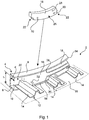
- Fig. 1 shows a part of a fuselage structure 2 of an aircraft.
- a circumferential frame element 4 is illustrated, which has an outer flange 6, an inner flange 8 as well as a web 10 extending therebetween, which connects both flanges 6 and 8 to form a C-like cross-sectional profile.
- the outer flange 6 is at a radial outermost position, which the inner flange 8 is at a radial inward location.
- Longitudinal stiffening elements in the form of stringers 12 extend perpendicular to the web 10 at a distance and parallel to each other.
- the outer flange 6 and outer flanges 14 of the stringers 12 form a supporting surface, onto which a skin 16 rests.
- This arrangement is a typical way of creating a fuselage structure 2, e.g. for a cylindrical fuselage of an aircraft with sufficient mechanical stability.
- a core of the invention lies in providing a fuel cell unit 18 into an available receiving space 20.
- a fuel cell unit 18 is inserted into the receiving space 20 that is delimited by two adjacent stringers 12 and a clearance between the two flanges 6 and 8.
- the fuel cell unit 18 comprises the shape of a segment of a ring with two lateral cut-outs 22 that conform the shape of the stringers 12.
- the thickness of the fuel cell unit 18 is exemplarily limited to a dimension less than the extension d from the web 10 to an outer edge 24 of the inner flange 24.
- the height of the fuel cell unit 18 is adapted to the clearance dimension h between the outer flange 6 and the inner flange 8.
- the fuel cell unit 18 comprises a first axial surface 26, into which a first output pole 28 and a second output pole 30 are integrated, which provide the generated electrical energy from the respective fuel cell unit 18.
- a water extraction port 32 is arranged at a bottom region of the fuel cell unit 18 for extracting water that accumulates during the fuel cell process.
- the water extraction port 32 may be connected to a water extraction duct 34, which runs on an interior side of the skin 16 and may lead to a water collecting device (not shown).
- a plurality of fuel cell units 18 may be distributed in the available space 20 of the structural component 4, such that the generated power can be chosen based on the actual demand at that location.
- Fig. 2 shows a principle setup of a fuel cell unit 18 in a very schematic illustration for a better understanding of its working principle.
- a first casing part 36 is shown, which is manufactured using an additive manufacturing method.
- the first casing part 36 is equipped with a fuel duct 38, which extends from a first lateral side 40 to a second lateral side 42.
- a plurality of distributing branches 44 are placed, which connect to the fuel line 38 and comprise a plurality of openings 46.
- the arrangement of fuel duct 38, branches 44 and openings 46 constitute a fuel distributor 48.
- the fuel distributor 48 is arranged at a region of the first casing part 36, which will be close to the inner flange 8 of the structural component 4.
- an oxidant line 50 extends from the first lateral side 40 to the second lateral side 42.
- a plurality of branching ducts 52 is coupled with the oxidant duct 50 and comprises a plurality of openings 54.
- the oxidant duct 50, the branching ducts 52 and the openings 54 constitute an oxidant distributor 56.
- the first casing part 36 is capable of receiving a plurality of individual fuel cells 58, which are arranged side by side in the first casing part 36.
- each fuel cell 58 comprises an anode 60, a membrane 62 and a cathode 64.
- a first bipolar plate 66 is arranged at a side of the anode 60 and is coupled with the fuel distributor 48, i.e. with the openings 46 of one of the branching ducts 44.
- Fuel e.g. a hydrogen containing gas or pure hydrogen, reaches the anode 60 through a plurality of conduits 68 in the first bipolar plate 66 and provides the positive pole for the generated electrical energy.
- the membrane 62 may be realized as a solid polymer membrane, which is a thin plastic film that is permeable to protons when saturated with water. Through the membrane, a proton exchange is conducted, while electrons can only pass from the anode 60 to the cathode 64 through the electric circuit attached to the respective fuel cell 58.
- a second bipolar plate 70 is arranged, which is coupled with the oxidant distributor 56 and comprises a series of conduits 72 for leading the oxidant to the cathode 64. Further, water that is created during the fuel cell process accumulates at the cathode 64 and reaches the conduits 72, where it needs to be extracted.
- An extraction port 32 may be arranged on the fuel cell unit 18 as shown in Fig. 1 .
- the individual fuel cell 58 is realized with a compact shape that is adapted to the available space inside the first casing part 36. Consequently, it may be feasible to also produce at least the metallic parts of a fuel cell 58 through additive manufacturing methods.
- a plurality of additional fuel cells 58 is to be arranged in the fuel cell unit 18.
- the illustration in Fig. 2 is merely schematic and shows for block-type fuel cells 58. However, it may be feasible to provide a rather high number of fuel cells 58 in a single fuel cell unit 18 to reach a required voltage level. Further, it is advantageous to periodically change the orientation of the individual fuel cells 58, such that a single second bipolar plate 70 can be used by two adjacent fuel cells 58.
- a third bipolar plate 74 may be arranged, which may be similar to the first bipolar plate 66, but contacts a cathode 64.
- fuel may enter the fuel duct 38, e.g. at the first lateral side 40 and flows to the second lateral side 42.
- fuel is distributed through the openings 46 of the branching ducts 44 to several bipolar plates 66 or 72, depending on the order inside the fuel cell unit 18. It may be feasible to put a plug or stopper into the fuel duct 38 at the second lateral side 42 if the fuel cell unit 18 is a single fuel cell unit 18 at a desired installation space. However, if further fuel cell units 18 are to be placed in an adjacent position, its fuel duct 38 may be connected to the fuel duct 38 of the adjacent fuel cell unit 18.
- the oxidant line 50 which may simply pass from the first lateral side 40 to the second lateral side 42.
- it may be connected to another oxidant line 50 of an adjacent fuel cell unit 18 or a plug or stopper may be arranged to close off the oxidant line 50.
- the fuel duct 38, the branching duct 44, the oxidant duct 50 as well as the branching ducts 52 are integrated into the first casing part 36 and the course of these may be more elaborate and compact.
- a second casing part 76 is provided, which is attachable to the first casing part 36.
- Fig. 1 For providing the cut-outs 22 shown in Fig. 1 , either the whole fuel cell unit 18 may be tailored to this available installation space or a further casing or flange may enclose the first and second casing parts 36 and 76 or be attached thereto. As stated above, Fig. 2 is merely schematic and the cut-outs 22 are left out for simplification.
- Fig. 3 shows the basic principle of interconnecting two adjacent fuel cell units 18 through connectors 78 and 80, which securely connect the fuel ducts 38 as well as the oxidant ducts 50 of two adjacent fuel cell units 18.
- the respective fuel duct 38 and oxidant duct 50 are to be closed through plugs 82 and 84.
- each fuel cell unit 18 may comprise two output poles 28 and 30, these may be connected through a serial connection (not shown).
Landscapes
- Engineering & Computer Science (AREA)
- Manufacturing & Machinery (AREA)
- Chemical & Material Sciences (AREA)
- Mechanical Engineering (AREA)
- Aviation & Aerospace Engineering (AREA)
- Sustainable Energy (AREA)
- Sustainable Development (AREA)
- Life Sciences & Earth Sciences (AREA)
- Chemical Kinetics & Catalysis (AREA)
- Electrochemistry (AREA)
- General Chemical & Material Sciences (AREA)
- Materials Engineering (AREA)
- Composite Materials (AREA)
- Fuel Cell (AREA)
Abstract
Description
- The invention relates to a method for integrating a fuel cell unit into a vehicle, a fuel cell system for integration into a vehicle as well as an aircraft comprising such a fuel cell system.
- Fuel cells for providing electrical energy based on a reaction of hydrogen and oxygen particularly in mobile applications are known for many decades. Various concepts for integrating fuel cells into large commercial aircraft exist. Concepts exist that are directed to replacing a common auxiliary power unit by a fuel cell, which also includes the common installation space in a tail section of a fuselage. For example, this is known from
EP 1 817 231 B1 . - Further concepts are known, which are based on the installation of relatively small individual fuel cell units for a more local generation of electrical energy at different places in an aircraft. For example,
EP 3 012 189 A1 shows the integration of fuel cell units in a galley installed in an aircraft cabin. - The installation of a fuel cell system for generating electrical energy in an aircraft requires dedicated installation spaces. Given a tendency to increase the efficiency of use of an interior space in the aircraft, while at the same time to further increase a passenger comfort, dedicated installation spaces for fuel cells for a local generation of electrical power are hard to provide.
- It is an object of the invention to meet the need for local installation spaces for integrating a fuel cell while at the same time the efficiency for using the interior space in a vehicle cabin or the such should not be hindered.
- This object is solved by a method for integrating a fuel cell unit into a structural component of a vehicle having the features of independent claim 1. Advantageous embodiments and further improvements may be gathered from the sub-claims and the following description.
- It is proposed a method for integrating a fuel cell unit into a structural component of a vehicle, the method comprising the steps of determining an available receiving space in an interior structural component of the vehicle, that allows receiving a fuel cell unit through insertion from outside the structural component into the receiving space, providing at least two casing parts that are assembleable to a closed casing, providing at least one fuel cell having an anode, a cathode and an electrolyte, assembling the casing parts and the at least one fuel cell to form the fuel cell unit, and inserting the fuel cell unit into the receiving space of the structural component. At least one of the casing parts is manufactured using an additive manufacturing method such that the fuel cell unit precisely fits into the determined receiving space. One of the casing parts comprises an exterior fuel inlet and an interior fuel distributor for leading fuel from the exterior fuel inlet to at least one fuel outlet couplable with each of the at least one fuel cell. One of the casing parts comprises an exterior oxidant inlet and an interior oxidant distributor for leading an oxidant from the exterior oxidant inlet to at least one oxidant outlet couplable with each of the at least one fuel cell.
- A first core aspect of the invention therefore lies in providing a compact fuel cell unit that is integratable into an already present structural component of a vehicle that has a commonly unused space for accommodating objects. A vehicle usually comprises a vehicle body, which is adapted for receiving passengers. The vehicle body often comprises an outer skin or hull, which surrounds the receiving space for passengers. The skin or hull is often attached to or comprises a certain stiffening structure that allows to maintain a desired shape of the vehicle body throughout the operation of the vehicle. The design of such a stiffening structure depends on the size, the purpose of the vehicle, the intended travelling velocities, expected accelerations and other parameters. A common design principle for larger vehicles is based on a combination of longitudinal stiffening elements and circumferential stiffening elements. In the case of an aircraft, the vehicle body in form of a fuselage may comprise a series of circumferential frame elements distributed at a distance to each other along a longitudinal axis of the fuselage. Further, often a series of longitudinal stiffening elements ("stringers") with a plurality of stringers arranged along a circumferential course at a distance to each other and parallel to the longitudinal axis is used.
- The frame elements often comprise a cross-sectional profile created by a set of flanges, which are curved to assume the respective local circumferential shape of the fuselage at the installation location of the frame element, wherein the flanges are mechanically connected by means of at least one web at a distance to each other. As an example, without limiting the core of the invention, the cross-section of such a frame element may be of an I-shape or a double-T-shape.
- While some frame elements particularly in the case of an aircraft may comprise thermal insulation material wrapped around them, there may some frame elements exist that are integrated in a plain manner. All of these may comprise a certain section, which encloses a certain volume, in which no other installation is present. For example, there may exist a certain volume enclosed by two opposite flanges and delimited by a web therebetween, which is completely empty. Such a volume may be regarded as a receiving space for integrating a device from outside the structural component without further preparing steps.
- By the manufacturing of a compact fuel cell unit with dimensions adapted to the respective receiving space it is possible to provide at least one, but preferably a multitude of local power sources within the vehicle.
- The method according to the invention may therefore start with the step of determining the available receiving space in an interior structural component of the vehicle. This may include measuring or retrieving the geometric parameters of the respective structural component which is intended to be equipped with a precisely fitted fuel cell unit. In this context it is stated that the dimensioning criteria refer to an unobstructed opening contour of the respective structural component, with which internal recesses, undercuts or other volume features are neglected that are only accessible from inside the structural component. It should be clear that the receiving space is to be considered a space that is accessible through inserting the fuel cell unit through an opening contour.
- Providing the casing parts may include an additive manufacturing method, which is also known as generative manufacturing method. Such a manufacturing method may comprise the subsequent local accumulation of particles from a selected material in a predetermined region in fine layers and hardening or curing of the respective layer. This generative manufacturing method may preferably be applied in the form of an ALM or SLM method. The materials characteristics of the manufactured product is equal or superior to a cast component. For hardening or curing in particular a laser is suitable as a heat source, and consequently as a special form of an ALM method an SLM method ("Selective Laser Melting") may be applied. It is advantageous in the method according to the invention to use powdery steel, stainless steel, aluminum alloys, titanium alloys or other meltable materials. For certain application fields the use of cobalt alloys and nickel alloys is also advantageous. For application in vehicles, and in particular in commercial aircraft, in particular powdery AlSilOMg or TiA16V4 is suitable. Further, since the fuel cell unit is not necessarily a load carrying component, also plastic materials may be used. The layer thicknesses realized in the method may depend on several factors such as, among other things, the output of the heat source used, the required accuracy, the materials characteristics and the reworkability. The smallest possible base area of a layer section depends on the geometric extension of the heat source. Thus, with particularly fine heat sources, for example a laser beam, a particularly fine structure may be manufactured. By matching the respective contour to be melted on, the process may be repeated until the desired casing part has been completed.
- The extent of the additive manufacturing depends on the shape and size of the respective structural component as well as of the required power output and hence the size of the fuel cell unit. If a rather complicated receiving space is present, it may be worthwhile to increase the extent of additive manufacturing, such that the fuel cell unit snugly fits into the receiving space without a labor intensive production method.
- The casing parts altogether have to be assembleable to constitute a closed casing with all necessary ports. Assembling the casing parts as well as the at least one fuel cell leads to the creation of a compact fuel cell unit, which is then insertable into the receiving space of the structural component.
- During the manufacturing of the respective casing parts, an integrated fuel distributor should be added, which is particularly required if a plurality of fuel cells is to be installed into the casing. The fuel distributor serves for receiving a fuel cell fuel from outside the fuel cell unit and for distributing it throughout the individual fuel cells.
- Further details and options of the fuel distributor are explained later on.
- In analogy to this, a casing part comprises an integrated oxidant distributor for leading an oxidant from an oxidant inlet to the at least one fuel cell. This is particularly required for a plurality of fuel cells integrated into the casing. Again, further details are explained later on.
- Altogether, the method allows to integrate fuel cells in a vehicle at a plurality of different locations in order to provide local generation of electrical power without having to allocate space in the cabin or other regions of the vehicle, but to use previously unused space in a structural component. By using previously unused space through occupation by fuel cell units, the efficiency of the use of space inside the vehicle is increased. At the same time, the amount of cabling for providing electrical energy to consumers inside the vehicle may be reduced, since local power generating fuel cells are simple to integrate.
- In an advantageous embodiment, the method further comprises providing at least a component of the at least one fuel cell through an additive manufacturing method. The individual receiving space for integration of a fuel cell unit depends on the region in the vehicle, which is to be equipped with fuel cell units. While some regions may provide regular geometrical structures, some may provide more complex shaped receiving spaces. As the shape of the at least one fuel cell unit needs to conform the receiving space it is clear that inside the at least one fuel cell unit also a more or less complex installation space is provided, which is used for holding the at least one fuel cell. The anode, the cathode and other core components of the at least one fuel cell may therefore be manufactured through an additive method, which leads to an optimum adaption of the at least one fuel cell.
- In another advantageous embodiment, providing at least one of the casing parts through using an additive manufacturing method includes integrating the at least one fuel duct having an external fuel input and at least one internal fuel output inside a walling of the respective casing part. The external fuel output may be created through providing an opening in an exterior side of the respective casing part, into which a suitable connection piece may be attached. The external side may be a side on a larger surface between delimiting edges or it may be provided directly into an edge surface of the respective casing part.
- In a still further embodiment, providing at least one of the casing parts through using an additive manufacturing method includes integrating the oxidant distributor through at least one oxidant line with an exterior oxidant input and at least one interior oxidant output into a walling of the respective casing part. Depending on the number of fuel cells integrated into the casing, the number of internal oxidant outlets may be chosen.
- In this regard it may be feasible to provide the respective additively manufactured casing part with a certain ridge or border, into which the fuel inlet and/or the oxidant inlet is integrated. This allows to place the fuel inlet and/or the oxidant inlet into a distance to a contact surface of the fuel cell unit.
- The method may further comprise inserting at least a second fuel cell unit into a respective at least one second receiving space of the structural component. Depending on the available receiving space or spaces it may not be possible to integrate a larger fuel cell unit that delivers the required electrical power alone, but it may be feasible to provide a plurality of individual fuel cell units in the same structural component. Hence, a plurality of independent fuel cell units may be used for generating electrical power and the voltage level of a combination of a plurality of fuel cells may be increased through a suitable electrical connection.
- Preferably, the method according to the invention comprises electrically connecting at least two of the fuel cell units in a serial connection. This increases the total voltage delivered by a plurality of fuel cell units.
- In case a plurality of fuel cell units is used, the method may also comprise connecting the external fuel inlet of one of the fuel cell units to an external fuel outlet of another one of the fuel cell units, which fuel outlet is coupled with the fuel duct of the respective one of the fuel cell units.
- In analogy to this, the method may further comprise connecting the external oxidant inlet of one of the fuel cell units to an external oxidant outlet of another one of the fuel cell units, which oxidant outlet is coupled with the oxidant duct of the respective one of the fuel cell units.
- If a plurality of fuel cell units is used, which are identical or at least very similar it may be advantageous to provide a plug to close an unused fuel and/or oxidant outlet.
- Still further, the method may comprise providing a coolant feed line and a coolant return line to a coolant inlet and a coolant outlet of the at least one fuel cell unit. The coolant may be provided by means of a coolant circuit having a coolant pump, a reservoir and at least one heat exchanger for dissipating heat. The heat exchanger may be arranged in a region of the vehicle that has a constant demand for heat or in a region where a constant flow of heat is absorbable reliably. As an advantageous improvement, the coolant circuit may comprise a plurality of heat exchangers, which are connected to bypass lines through a series of valves, such that each heat exchanger may selectively be bringable in a fluid communication with the coolant circuit or may selectively be deactivatable. For example, if heat consuming devices in a kitchen are to be operated, one of the plurality of heat exchangers may deliver this heat. Further, in case the vehicle is an aircraft, a skin heat exchanger may be used at cruise altitudes in which the ambient temperature is particularly low and suitable for dissipating heat into the environment of the aircraft. For transferring the heat created in the fuel cell units, these may be equipped with components having certain coolant conduits in heat generating components and/or in at least one of the casing parts, which coolant conduits lead fresh and cold coolant into the respective component and transfer heat into the coolant, which then exits the respective fuel cell unit.
- Further, the method may also comprise coupling water extraction outlets of the fuel cell units with a water extraction duct. For this purpose, the water extraction duct may be installed in the vehicle and be coupled with a water receiving device. This may be a device that simply stores in the interior of the vehicle or dissipates it to the surrounding of the aircraft. As an alternative, water consuming devices, such as a galley or a lavatory, may be provided with the extracted water. In the latter case, the installation space of the at least one fuel cell unit may be chosen to be as near as possible to the respective water consuming devices.
- The invention also relates to a fuel cell system for integration into a structural component of a vehicle, the system having at least one fuel cell unit comprising at least one fuel cell having an anode, a cathode and an electrolyte; a closed fuel cell unit casing having at least two casing parts; wherein one of the casing parts comprises an exterior fuel inlet and an interior fuel distributor for leading a fuel from the exterior fuel inlet to at least one fuel outlet couplable with each of the at least one fuel cell, and wherein one of the casing parts comprises an exterior oxidant inlet and an interior oxidant distributor for leading an oxidant from the exterior oxidant inlet to at least one oxidant outlet couplable with each of the at least one fuel cell, and wherein at least one of the casing parts is manufactured using an additive manufacturing method such that the fuel cell unit precisely fits into a receiving space of a structural component of a vehicle.
- In an advantageous embodiment, the system comprises a plurality of fuel cell units, wherein at least a subset of the plurality of the fuel cell units has at least one of a fuel outlet connected to the fuel inlet of the respective fuel cell unit and an oxidant outlet connected to the oxidant inlet of the respective fuel cell unit, wherein the at least one of the fuel outlet and the oxidant outlet is connected to a respective one of a fuel inlet and an oxidant inlet of another fuel cell unit.
- In a still further embodiment, the shape of the fuel cell unit is curved so as to fit into a curved circumferential frame element having at least one flange that is attached to a web preferably, but not exclusively, in a right angle. Such a frame element may be integrated as a circumferential frame element in an aircraft fuselage, wherein the receiving space may have a C-shaped cross-sectional profile.
- Still further, the fuel cell unit may comprise at least one lateral recess or cut-out, which is adapted to fit onto a longitudinal stiffening part that intersects with an outer flange and the web of the circumferential frame element. As stated above, exemplarily an aircraft often comprises circumferential frames as well as longitudinal stringers, which commonly intersect with each other, such that the outer flange of the frame element and the web comprise openings, through which the longitudinal stiffening parts extend. Hence, a fuel cell unit may be designed so as to fit into an available receiving space that is at one side delimited by the longitudinal stiffening element, onto which the at least one recess or cut-out snugly fits.
- Attaching the at least one fuel cell unit may be conducted through a clip-on-connection. By using a clip-on-connection it is simple to replace a fuel cell unit in case of a malfunction or if the power demands are changed. The structural component of the vehicle does not need to be modified or equipped with fasteners, such that they may remain completely unchanged. However, such a clip-on-connection should be stable enough to always ensure maintaining a position of the fuel cell unit under any possible operation condition of the vehicle. In case of the installation in an aircraft, a landing shock, the occurrence of turbulences and the expected accelerations in all spatial directions under consideration of regulated safety factors have to be taken into account.
- In an alternative embodiment, the attaching may be realized through the use of screws or bolts. Hence, a reliable and extremely stable mechanical connection between the fuel cell unit and the respective structural component can be created. This, however, requires a modification of the structural component. As a side effect, this leads to a combination of at least a section of the respective structural component and the fuel cell unit to form an integral component with a required load carrying capability. This means, that on the one hand, the fuel cell unit supports the respective structural component in absorbing certain loads that occur during a normal operation of the vehicle. On the other hand, the structural component may support the mechanical properties of the casing of the fuel cell. Altogether, the thickness of the casing or of the respective structural component in the region of the receiving space may be reduced. This consequently reduces the total weight introduced by the fuel cell unit to a value that would be below the weight of a fuel cell device that is arranged in another region of the vehicle.
- The invention further relates to an aircraft, comprising a fuselage having a series of frame elements arranged at a distance to each other and at least one fuel cell system according to the above description. At least one frame element of the series of frames comprises a first flange and a web connected to the first flange, wherein at least one fuel cell unit of the at least one fuel cell system is arranged in a profile space defined by the first flange and the web.
- In another advantageous embodiment, the at least one frame element comprises a second flange connected to the web, wherein the profile space for integration of the at least one fuel cell is defined between the first flange, the second flange and the web.
- Still further, a plurality of fuel cell units may be arranged in at least one frame element of the series of frames, wherein the plurality of fuel cell units is electrically connected to each other in a series connection.
- As stated further above, the external fuel inlet of one of the fuel cell units may also be connected to an external fuel outlet of another one of the fuel cell units, which fuel outlet is coupled with the fuel duct of the respective one of the fuel cell units.
- In analogy to this, the external oxidant inlet of one of the fuel cell units may be connected to an external oxidant outlet of another one of the fuel cell units, which oxidant outlet is coupled with the oxidant duct of the respective one of the fuel cell units.
- Other characteristics, advantages and potential applications of the present invention result from the following description of the exemplary embodiments illustrated in the figures. In this respect, all described and/or graphically illustrated characteristics also form the object of the invention individually and in arbitrary combination regardless of their composition in the individual claims or their references to other claims. Furthermore, identical or similar objects are identified by the same reference symbols in the figures.
-
Fig. 1 shows a part of a fuselage structure of an aircraft with an integrated fuel cell unit. -
Fig. 2 shows a principle setup of a fuel cell unit. -
Fig. 3 shows a connection of two adjacent fuel cell units. -
Fig. 1 shows a part of afuselage structure 2 of an aircraft. Acircumferential frame element 4 is illustrated, which has anouter flange 6, aninner flange 8 as well as aweb 10 extending therebetween, which connects bothflanges outer flange 6 is at a radial outermost position, which theinner flange 8 is at a radial inward location. - Longitudinal stiffening elements in the form of
stringers 12 extend perpendicular to theweb 10 at a distance and parallel to each other. Theouter flange 6 andouter flanges 14 of thestringers 12 form a supporting surface, onto which askin 16 rests. This arrangement is a typical way of creating afuselage structure 2, e.g. for a cylindrical fuselage of an aircraft with sufficient mechanical stability. - Using an arrangement of two
flanges web 10 leads to a particularly high geometrical moment of inertia. However, in common installations in commercial aircraft, the volume between theouter flange 6 and theinner flange 8 remains substantially unused. - A core of the invention lies in providing a
fuel cell unit 18 into an available receivingspace 20. In this exemplary embodiment, afuel cell unit 18 is inserted into the receivingspace 20 that is delimited by twoadjacent stringers 12 and a clearance between the twoflanges fuel cell unit 18 comprises the shape of a segment of a ring with two lateral cut-outs 22 that conform the shape of thestringers 12. The thickness of thefuel cell unit 18 is exemplarily limited to a dimension less than the extension d from theweb 10 to anouter edge 24 of theinner flange 24. The height of thefuel cell unit 18 is adapted to the clearance dimension h between theouter flange 6 and theinner flange 8. - As explained in the following, at least parts of the
fuel cell unit 18 are manufactured using an additive manufacturing method. Exemplarily, thefuel cell unit 18 comprises a firstaxial surface 26, into which afirst output pole 28 and asecond output pole 30 are integrated, which provide the generated electrical energy from the respectivefuel cell unit 18. Further, awater extraction port 32 is arranged at a bottom region of thefuel cell unit 18 for extracting water that accumulates during the fuel cell process. For example, thewater extraction port 32 may be connected to awater extraction duct 34, which runs on an interior side of theskin 16 and may lead to a water collecting device (not shown). - As apparent in
Fig. 1 , a plurality offuel cell units 18 may be distributed in theavailable space 20 of thestructural component 4, such that the generated power can be chosen based on the actual demand at that location. -
Fig. 2 shows a principle setup of afuel cell unit 18 in a very schematic illustration for a better understanding of its working principle. Here, afirst casing part 36 is shown, which is manufactured using an additive manufacturing method. Thefirst casing part 36 is equipped with afuel duct 38, which extends from a firstlateral side 40 to a secondlateral side 42. On this course, a plurality of distributingbranches 44 are placed, which connect to thefuel line 38 and comprise a plurality ofopenings 46. The arrangement offuel duct 38,branches 44 andopenings 46 constitute afuel distributor 48. In this example, thefuel distributor 48 is arranged at a region of thefirst casing part 36, which will be close to theinner flange 8 of thestructural component 4. - In a region of the
first casing part 36, which extends at a substantially right angle to the before mentioned part, anoxidant line 50 extends from the firstlateral side 40 to the secondlateral side 42. A plurality of branchingducts 52 is coupled with theoxidant duct 50 and comprises a plurality ofopenings 54. Theoxidant duct 50, the branchingducts 52 and theopenings 54 constitute anoxidant distributor 56. - The
first casing part 36 is capable of receiving a plurality ofindividual fuel cells 58, which are arranged side by side in thefirst casing part 36. - Exemplarily, each
fuel cell 58 comprises ananode 60, amembrane 62 and acathode 64. A firstbipolar plate 66 is arranged at a side of theanode 60 and is coupled with thefuel distributor 48, i.e. with theopenings 46 of one of the branchingducts 44. Fuel, e.g. a hydrogen containing gas or pure hydrogen, reaches theanode 60 through a plurality ofconduits 68 in the firstbipolar plate 66 and provides the positive pole for the generated electrical energy. - The
membrane 62 may be realized as a solid polymer membrane, which is a thin plastic film that is permeable to protons when saturated with water. Through the membrane, a proton exchange is conducted, while electrons can only pass from theanode 60 to thecathode 64 through the electric circuit attached to therespective fuel cell 58. - At a side of the
cathode 64, a secondbipolar plate 70 is arranged, which is coupled with theoxidant distributor 56 and comprises a series ofconduits 72 for leading the oxidant to thecathode 64. Further, water that is created during the fuel cell process accumulates at thecathode 64 and reaches theconduits 72, where it needs to be extracted. Anextraction port 32 may be arranged on thefuel cell unit 18 as shown inFig. 1 . - The
individual fuel cell 58 is realized with a compact shape that is adapted to the available space inside thefirst casing part 36. Consequently, it may be feasible to also produce at least the metallic parts of afuel cell 58 through additive manufacturing methods. - If the available installation space inside a
fuel cell unit 18 allows it and in case a certain voltage is required that clearly exceeds a typical PEM voltage of 0.6 V to 0.7 V at full load, a plurality ofadditional fuel cells 58 is to be arranged in thefuel cell unit 18. The illustration inFig. 2 is merely schematic and shows for block-type fuel cells 58. However, it may be feasible to provide a rather high number offuel cells 58 in a singlefuel cell unit 18 to reach a required voltage level. Further, it is advantageous to periodically change the orientation of theindividual fuel cells 58, such that a single secondbipolar plate 70 can be used by twoadjacent fuel cells 58. At a lateral end opposite the firstbipolar plate 66, a thirdbipolar plate 74 may be arranged, which may be similar to the firstbipolar plate 66, but contacts acathode 64. - During operation of the fuel cell unit, fuel may enter the
fuel duct 38, e.g. at the firstlateral side 40 and flows to the secondlateral side 42. On this course, fuel is distributed through theopenings 46 of the branchingducts 44 to severalbipolar plates fuel cell unit 18. It may be feasible to put a plug or stopper into thefuel duct 38 at the secondlateral side 42 if thefuel cell unit 18 is a singlefuel cell unit 18 at a desired installation space. However, if furtherfuel cell units 18 are to be placed in an adjacent position, itsfuel duct 38 may be connected to thefuel duct 38 of the adjacentfuel cell unit 18. The same applies for theoxidant line 50, which may simply pass from the firstlateral side 40 to the secondlateral side 42. Here, it may be connected to anotheroxidant line 50 of an adjacentfuel cell unit 18 or a plug or stopper may be arranged to close off theoxidant line 50. - For increasing the efficiency of using the space available for the
fuel cell unit 18, it is feasible to manufacture at least thefirst casing part 36 with an additive manufacturing method. Hence, thefuel duct 38, the branchingduct 44, theoxidant duct 50 as well as the branchingducts 52 are integrated into thefirst casing part 36 and the course of these may be more elaborate and compact. - For closing off the
first casing part 36 to form a closed casing, asecond casing part 76 is provided, which is attachable to thefirst casing part 36. - For providing the cut-
outs 22 shown inFig. 1 , either the wholefuel cell unit 18 may be tailored to this available installation space or a further casing or flange may enclose the first andsecond casing parts Fig. 2 is merely schematic and the cut-outs 22 are left out for simplification. -
Fig. 3 shows the basic principle of interconnecting two adjacentfuel cell units 18 throughconnectors fuel ducts 38 as well as theoxidant ducts 50 of two adjacentfuel cell units 18. At the end of a chain offuel cell units 18, therespective fuel duct 38 andoxidant duct 50 are to be closed throughplugs fuel cell unit 18 may comprise twooutput poles fuel cell unit 18 to a certain power electronics unit, which may tolerate a failure of individualfuel cell units 18 without a total voltage having a failure. - In addition, it should be pointed out that "comprising" does not exclude other elements or steps, and "a" or "an" does not exclude a plural number. Furthermore, it should be pointed out that characteristics or steps which have been described with reference to one of the above exemplary embodiments may also be used in combination with other characteristics or steps of other exemplary embodiments described above. Reference characters in the claims are not to be interpreted as limitations.
Claims (15)
- Method for integrating at least one fuel cell unit (18) for integration into a structural component of a vehicle, comprising the steps of:- determining an available receiving space (20) in an interior structural component (4) of the vehicle, that allows receiving a fuel cell unit (18) through insertion from outside the structural component (4) into the receiving space (4),- providing at least two casing parts (36, 76) that are assembleable to a closed casing,- providing at least one fuel cell (58) having an anode (60), a cathode (64) and an electrolyte,- assembling the casing parts (36, 76) and the at least one fuel cell (58) to form the fuel cell unit (18), and- inserting the at least one fuel cell unit (18) into the receiving space (4) of the structural component,wherein at least one of the casing parts (36, 76) is manufactured using an additive manufacturing method such that the fuel cell unit (18) precisely fits into the determined receiving space (4),
wherein one of the casing parts (36, 76) comprises an exterior fuel inlet and an interior fuel distributor (48) for leading a fuel from the exterior fuel inlet to at least one fuel outlet couplable with each of the at least one fuel cell (58), and
wherein one of the casing parts (36, 76) comprises an exterior oxidant inlet and an interior oxidant distributor for leading an oxidant from the exterior oxidant inlet to at least one oxidant outlet couplable with each of the at least one fuel cell (58). - Method according to claim 1,
further comprising providing at least a component of the at least one fuel cell (58) through an additive manufacturing method - Method of claim 1 or 2,
wherein providing at least one of the casing parts (36, 76) by manufacturing using an additive manufacturing method includes integrating the at least one fuel duct (38) having an external fuel input and at least one internal fuel output inside a walling of the respective casing part (36, 76). - Method of any of the preceding claims,
wherein providing at least one of the casing parts (36, 76) by manufacturing using an additive manufacturing method includes integrating the at least one oxidant duct (50) having an external oxidant input and at least one internal oxidant output inside a walling of the respective casing part (36, 76). - Method of any of the preceding claims,
further comprising inserting at least a second fuel cell unit (18) into a respective at least one second receiving space (4) of the structural component. - Method of claim 5,
further comprising electrically connecting at least two of the fuel cell units (18) in a serial connection. - Method of claim 5 or 6,
further comprising connecting the external fuel inlet of one of the fuel cell units (18) to an external fuel outlet of another one of the fuel cell units (18), which fuel outlet is coupled with the fuel duct (38) of the respective one of the fuel cell units (18). - Method of any of claims 5 to 7,
further comprising connecting the external oxidant inlet of one of the fuel cell units (18) to an external oxidant outlet of another one of the fuel cell units (18), which oxidant outlet is coupled with the oxidant duct (50) of the respective one of the fuel cell units (18). - Fuel cell system for integration into a structural component of a vehicle, the system having at least one fuel cell unit (18) comprising:- at least one fuel cell (58) having an anode (60), a cathode (64) and an electrolyte,- a closed fuel cell unit (18) casing having at least two casing parts (36, 76), wherein one of the casing parts (36, 76) comprises an exterior fuel inlet and an interior fuel distributor (48) for leading a fuel from the exterior fuel inlet to at least one fuel outlet couplable with each of the at least one fuel cell, and wherein one of the casing parts (36, 76) comprises an exterior oxidant inlet and an interior oxidant distributor for leading an oxidant from the exterior oxidant inlet to at least one oxidant outlet couplable with each of the at least one fuel cell (58),wherein at least one of the casing parts (36, 76) is manufactured using an additive manufacturing method such that the fuel cell unit (18) precisely fits into a receiving space (4) of a structural component of a vehicle.
- Fuel cell system of claim 9,
comprising a plurality of fuel cell units (18), wherein at least a subset of the plurality of the fuel cell units (18) has at least one of a fuel outlet connected to the fuel inlet of the respective fuel cell unit (18) and an oxidant outlet connected to the oxidant inlet of the respective fuel cell unit (18), wherein the at least one of the fuel outlet and the oxidant outlet is connected to a respective one of a fuel inlet and an oxidant inlet of another fuel cell unit (18). - Fuel cell system of claim 9 or 10,
wherein the shape of the at least one fuel cell unit (18) is curved so as to fit into a curved circumferential frame element having at least one flange (6, 8) that is attached to a web (10). - Fuel cell system of claim 11,
wherein the fuel cell unit (18) comprises at least one lateral recess or cut-out, which is adapted to fit onto a longitudinal stiffening part that intersects with an outer flange (6) and the web (10) of the circumferential frame element. - Aircraft, comprising- a fuselage having a series of frames arranged at a distance to each other,- at least one fuel cell system according to claims 1 to 12,wherein at least one frame of the series of frames comprises a first flange (6, 8) and a web (10) connected to the first flange (6, 8),
wherein at least one fuel cell unit (18) of the at least one fuel cell system is arranged in a profile space defined by the first flange (6, 8) and the web (10). - Aircraft of claim 13,
wherein the at least one frame comprises a second flange (6, 8) connected to the web (10), wherein the profile space for integration of the at least one fuel cell (58) is defined between the first flange (6, 8), the second flange (6, 8) and the web (10). - Aircraft of claim 13 or 14,
wherein a plurality of fuel cell units (18) are arranged in at least one frame of the series of frames, wherein the plurality of fuel cell units (18) are electrically connected to each other in a series connection.
Priority Applications (4)
| Application Number | Priority Date | Filing Date | Title |
|---|---|---|---|
| ES16204012T ES2756340T3 (en) | 2016-12-14 | 2016-12-14 | Method for adapting and integrating a fuel cell unit in a vehicle |
| EP16204012.5A EP3336948B1 (en) | 2016-12-14 | 2016-12-14 | Method for tailoring and integrating a fuel cell unit into a vehicle |
| US15/827,248 US10826104B2 (en) | 2016-12-14 | 2017-11-30 | Method for tailoring and integrating a fuel cell unit into a vehicle |
| CN201711317829.4A CN108216648B (en) | 2016-12-14 | 2017-12-12 | Method for adapting and integrating a fuel cell unit into a vehicle |
Applications Claiming Priority (1)
| Application Number | Priority Date | Filing Date | Title |
|---|---|---|---|
| EP16204012.5A EP3336948B1 (en) | 2016-12-14 | 2016-12-14 | Method for tailoring and integrating a fuel cell unit into a vehicle |
Publications (2)
| Publication Number | Publication Date |
|---|---|
| EP3336948A1 true EP3336948A1 (en) | 2018-06-20 |
| EP3336948B1 EP3336948B1 (en) | 2019-09-11 |
Family
ID=57569983
Family Applications (1)
| Application Number | Title | Priority Date | Filing Date |
|---|---|---|---|
| EP16204012.5A Active EP3336948B1 (en) | 2016-12-14 | 2016-12-14 | Method for tailoring and integrating a fuel cell unit into a vehicle |
Country Status (4)
| Country | Link |
|---|---|
| US (1) | US10826104B2 (en) |
| EP (1) | EP3336948B1 (en) |
| CN (1) | CN108216648B (en) |
| ES (1) | ES2756340T3 (en) |
Families Citing this family (32)
| Publication number | Priority date | Publication date | Assignee | Title |
|---|---|---|---|---|
| US11923569B2 (en) | 2021-04-26 | 2024-03-05 | General Electric Company | High performance fuel cells |
| US12202616B2 (en) | 2021-11-04 | 2025-01-21 | General Electric Company | Relight of a propulsion system with a fuel cell |
| CN114147954A (en) * | 2021-12-01 | 2022-03-08 | 深圳市中蓝绿源科技有限公司 | Method for directly printing methanol fuel cell shell by adopting 3D printing technology |
| US11794912B2 (en) | 2022-01-04 | 2023-10-24 | General Electric Company | Systems and methods for reducing emissions with a fuel cell |
| US12037952B2 (en) | 2022-01-04 | 2024-07-16 | General Electric Company | Systems and methods for providing output products to a combustion chamber of a gas turbine engine |
| US11933216B2 (en) | 2022-01-04 | 2024-03-19 | General Electric Company | Systems and methods for providing output products to a combustion chamber of a gas turbine engine |
| US12123361B2 (en) | 2022-01-04 | 2024-10-22 | General Electric Company | Systems and methods for providing output products to a combustion chamber of a gas turbine engine |
| US11719441B2 (en) | 2022-01-04 | 2023-08-08 | General Electric Company | Systems and methods for providing output products to a combustion chamber of a gas turbine engine |
| US11970282B2 (en) | 2022-01-05 | 2024-04-30 | General Electric Company | Aircraft thrust management with a fuel cell |
| US12034298B2 (en) | 2022-01-10 | 2024-07-09 | General Electric Company | Power source for an aircraft |
| US11804607B2 (en) | 2022-01-21 | 2023-10-31 | General Electric Company | Cooling of a fuel cell assembly |
| US12074350B2 (en) | 2022-01-21 | 2024-08-27 | General Electric Company | Solid oxide fuel cell assembly |
| US12037124B2 (en) | 2022-01-21 | 2024-07-16 | General Electric Company | Systems and method of operating a fuel cell assembly |
| US12573647B2 (en) | 2022-01-21 | 2026-03-10 | General Electric Company | Solid oxide fuel cell assembly |
| US12351329B2 (en) | 2022-01-21 | 2025-07-08 | General Electric Company | Systems and method of operating a fuel cell assembly |
| US12129789B2 (en) | 2022-02-21 | 2024-10-29 | General Electric Company | Systems and method of operating a fuel cell assembly, a gas turbine engine, or both |
| US11967743B2 (en) | 2022-02-21 | 2024-04-23 | General Electric Company | Modular fuel cell assembly |
| US12170390B2 (en) | 2022-02-21 | 2024-12-17 | General Electric Company | Systems and method of operating a fuel cell assembly, a gas turbine engine, or both |
| US12025061B2 (en) | 2022-04-04 | 2024-07-02 | General Electric Company | Gas turbine engine with fuel cell assembly |
| US12412914B2 (en) | 2022-05-16 | 2025-09-09 | General Electric Company | Environmental control system having a fuel cell assembly |
| US12428164B2 (en) | 2022-05-16 | 2025-09-30 | General Electric Company | Environmental control system having a fuel cell assembly |
| US12043406B2 (en) | 2022-05-27 | 2024-07-23 | General Electric Company | Method of operating a fuel cell assembly for an aircraft |
| US11817700B1 (en) | 2022-07-20 | 2023-11-14 | General Electric Company | Decentralized electrical power allocation system |
| US12301002B2 (en) | 2022-08-26 | 2025-05-13 | General Electric Company | Power dispatch control system for multiple power generation sources |
| US11859820B1 (en) | 2022-11-10 | 2024-01-02 | General Electric Company | Gas turbine combustion section having an integrated fuel cell assembly |
| US12078350B2 (en) | 2022-11-10 | 2024-09-03 | General Electric Company | Gas turbine combustion section having an integrated fuel cell assembly |
| US12567595B2 (en) | 2022-11-10 | 2026-03-03 | General Electric Company | Gas turbine combustion section having an integrated fuel cell assembly |
| US12240613B2 (en) | 2022-11-10 | 2025-03-04 | General Electric Company | Gas turbine combustion section having an integrated fuel cell assembly |
| US11923586B1 (en) | 2022-11-10 | 2024-03-05 | General Electric Company | Gas turbine combustion section having an integrated fuel cell assembly |
| CN118532265A (en) | 2023-02-23 | 2024-08-23 | 通用电气公司 | Gas turbine engine and fuel cell components |
| CN118532263A (en) | 2023-02-23 | 2024-08-23 | 通用电气公司 | Gas turbine engine and fuel cell components |
| CN118532266A (en) | 2023-02-23 | 2024-08-23 | 通用电气公司 | Gas turbine engine and fuel cell components |
Citations (7)
| Publication number | Priority date | Publication date | Assignee | Title |
|---|---|---|---|---|
| US20070090786A1 (en) * | 2004-07-21 | 2007-04-26 | Angstrom Power Incorporated | Devices powered by conformable fuel cells |
| EP2443035A2 (en) * | 2009-06-17 | 2012-04-25 | Airbus SAS | Aircraft provided with a fuel cell system |
| WO2014021970A2 (en) * | 2012-05-08 | 2014-02-06 | Battelle Memorial Institute | Multifunctional cell for structural applications |
| EP1817231B1 (en) | 2004-12-03 | 2014-02-12 | Airbus Operations GmbH | Supply system for the energy supply in an aircraft, aircraft and method for supplying an aircraft with energy |
| EP2766947A1 (en) * | 2011-10-14 | 2014-08-20 | Topsøe Fuel Cell A/S | Stack assembly |
| EP3012189A1 (en) | 2014-10-22 | 2016-04-27 | Airbus Operations GmbH | Galley system, method for operating electrical galley devices and use of a fuel cell in a galley system |
| GB2537935A (en) * | 2015-05-01 | 2016-11-02 | Intelligent Energy Ltd | Aerial vehicle |
Family Cites Families (10)
| Publication number | Priority date | Publication date | Assignee | Title |
|---|---|---|---|---|
| US7281681B2 (en) * | 2000-04-03 | 2007-10-16 | Aerovironment Inc. | Hydrogen powered aircraft |
| GB0024106D0 (en) * | 2000-10-03 | 2000-11-15 | Rolls Royce Plc | A solid oxide fuel cell stack and a method of manufacturing a solid oxide fuel cell stack |
| JP4135455B2 (en) * | 2002-10-04 | 2008-08-20 | 日産自動車株式会社 | Mobile fuel cell system |
| US6886861B2 (en) * | 2003-02-19 | 2005-05-03 | General Motors Corporation | Trunk mounted fuel tank assembly |
| JP4311428B2 (en) * | 2006-09-19 | 2009-08-12 | カシオ計算機株式会社 | Reactor |
| US20080299423A1 (en) * | 2007-05-30 | 2008-12-04 | Laven Arne | Fuel cell systems with maintenance hydration |
| DE102007061991B4 (en) * | 2007-12-21 | 2009-12-03 | Airbus Deutschland Gmbh | Fuel cell system module, set of fuel cell system modules and use of a fuel cell system module in an aircraft |
| JP5254673B2 (en) * | 2008-06-13 | 2013-08-07 | 本田技研工業株式会社 | Fuel cell stack |
| JP5695220B2 (en) * | 2012-01-26 | 2015-04-01 | 本田技研工業株式会社 | Fuel cell vehicle |
| JP6166203B2 (en) * | 2014-03-26 | 2017-07-19 | 本田技研工業株式会社 | Fuel cell stack |
-
2016
- 2016-12-14 ES ES16204012T patent/ES2756340T3/en active Active
- 2016-12-14 EP EP16204012.5A patent/EP3336948B1/en active Active
-
2017
- 2017-11-30 US US15/827,248 patent/US10826104B2/en active Active
- 2017-12-12 CN CN201711317829.4A patent/CN108216648B/en active Active
Patent Citations (7)
| Publication number | Priority date | Publication date | Assignee | Title |
|---|---|---|---|---|
| US20070090786A1 (en) * | 2004-07-21 | 2007-04-26 | Angstrom Power Incorporated | Devices powered by conformable fuel cells |
| EP1817231B1 (en) | 2004-12-03 | 2014-02-12 | Airbus Operations GmbH | Supply system for the energy supply in an aircraft, aircraft and method for supplying an aircraft with energy |
| EP2443035A2 (en) * | 2009-06-17 | 2012-04-25 | Airbus SAS | Aircraft provided with a fuel cell system |
| EP2766947A1 (en) * | 2011-10-14 | 2014-08-20 | Topsøe Fuel Cell A/S | Stack assembly |
| WO2014021970A2 (en) * | 2012-05-08 | 2014-02-06 | Battelle Memorial Institute | Multifunctional cell for structural applications |
| EP3012189A1 (en) | 2014-10-22 | 2016-04-27 | Airbus Operations GmbH | Galley system, method for operating electrical galley devices and use of a fuel cell in a galley system |
| GB2537935A (en) * | 2015-05-01 | 2016-11-02 | Intelligent Energy Ltd | Aerial vehicle |
Also Published As
| Publication number | Publication date |
|---|---|
| US10826104B2 (en) | 2020-11-03 |
| CN108216648B (en) | 2022-12-16 |
| US20180166734A1 (en) | 2018-06-14 |
| ES2756340T3 (en) | 2020-04-27 |
| CN108216648A (en) | 2018-06-29 |
| EP3336948B1 (en) | 2019-09-11 |
Similar Documents
| Publication | Publication Date | Title |
|---|---|---|
| US10826104B2 (en) | Method for tailoring and integrating a fuel cell unit into a vehicle | |
| EP3525259B1 (en) | Aircraft or spacecraft having a structural component with a battery arrangement integrated therein | |
| US20240234871A1 (en) | Thermal management of a liquid cooled module | |
| US9437905B2 (en) | Traction battery thermal plate manifold | |
| US10293945B2 (en) | Aircraft having a redundant and efficient bleed system | |
| EP2959521B1 (en) | Aircraft including mitigation system for rechargeable batteries | |
| CN105406099B (en) | The standard design and collision protection that fuel-cell stack assembly-fuel cell stacks | |
| EP2979731B1 (en) | Supply system and method for providing electric energy, oxygen depleted air and water as well and aircraft having such a supply system | |
| CN108022727B (en) | Inductor cooling system and method | |
| US11276869B2 (en) | Hydrogen fuel cell stack and method for upgrading a hydrogen fuel cell stack | |
| CN106374128B (en) | Modular Fuel Cell System | |
| EP2767514A1 (en) | Ion exchanger and cooling device equipped with ion exchanger | |
| DE102014226249A1 (en) | Battery system with heat conduction | |
| US12043406B2 (en) | Method of operating a fuel cell assembly for an aircraft | |
| EP4142000B1 (en) | Systems and methods for ventilating a fuel cell enclosure | |
| DE102013208365B4 (en) | ICE RESISTANT VALVE FOR USE IN A FUEL CELL SYSTEM, METHOD OF INHIBITING FREEZE CLOSED BLOCKAGE OF A REACTANT FLOW PATH IN AN AUTOMOTIVE FUEL CELL SYSTEM, AND METHOD OF SUPPORTING COLD CATALYTIC HEATER DURING A FUEL CELL COLD STACK | |
| US11719493B2 (en) | Cooler | |
| CN206388788U (en) | Modular Fuel Cell System | |
| US12119465B2 (en) | Heat exchanger assemblies and cooling systems for evtol aircraft | |
| CN118145023B (en) | Satellite electric propulsion storage unit device and design method | |
| US12571109B2 (en) | Fuel cell system | |
| EP4134986A2 (en) | Electric component for an electric system | |
| EP4160761A1 (en) | Systems and methods for liquid heating balance of plant components of a fuel cell module | |
| DE102023114478A1 (en) | Cooling of traction accumulators with round cell arrays by cooling structures with plates and cooling coils as well as equalization of the internal aging behavior of the traction accumulator | |
| US20250253361A1 (en) | Cooling system for fuel cell onboard a vehicle including auxiliary evaporative cooling |
Legal Events
| Date | Code | Title | Description |
|---|---|---|---|
| PUAI | Public reference made under article 153(3) epc to a published international application that has entered the european phase |
Free format text: ORIGINAL CODE: 0009012 |
|
| STAA | Information on the status of an ep patent application or granted ep patent |
Free format text: STATUS: THE APPLICATION HAS BEEN PUBLISHED |
|
| AK | Designated contracting states |
Kind code of ref document: A1 Designated state(s): AL AT BE BG CH CY CZ DE DK EE ES FI FR GB GR HR HU IE IS IT LI LT LU LV MC MK MT NL NO PL PT RO RS SE SI SK SM TR |
|
| AX | Request for extension of the european patent |
Extension state: BA ME |
|
| STAA | Information on the status of an ep patent application or granted ep patent |
Free format text: STATUS: REQUEST FOR EXAMINATION WAS MADE |
|
| 17P | Request for examination filed |
Effective date: 20181218 |
|
| RBV | Designated contracting states (corrected) |
Designated state(s): AL AT BE BG CH CY CZ DE DK EE ES FI FR GB GR HR HU IE IS IT LI LT LU LV MC MK MT NL NO PL PT RO RS SE SI SK SM TR |
|
| REG | Reference to a national code |
Ref country code: DE Ref legal event code: R079 Ref document number: 602016020315 Country of ref document: DE Free format text: PREVIOUS MAIN CLASS: H01M0008247500 Ipc: B22F0003000000 |
|
| RIC1 | Information provided on ipc code assigned before grant |
Ipc: B33Y 80/00 20150101ALI20190221BHEP Ipc: B29C 64/153 20170101ALI20190221BHEP Ipc: B33Y 10/00 20150101ALI20190221BHEP Ipc: B22F 5/10 20060101ALI20190221BHEP Ipc: H01M 8/2484 20160101ALI20190221BHEP Ipc: B64C 1/06 20060101ALI20190221BHEP Ipc: H01M 8/2475 20160101ALI20190221BHEP Ipc: B22F 3/00 20060101AFI20190221BHEP Ipc: B22F 3/105 20060101ALI20190221BHEP Ipc: H01M 8/2483 20160101ALI20190221BHEP Ipc: B64D 41/00 20060101ALI20190221BHEP Ipc: B64D 11/00 20060101ALI20190221BHEP Ipc: B29C 67/00 20170101ALI20190221BHEP |
|
| GRAP | Despatch of communication of intention to grant a patent |
Free format text: ORIGINAL CODE: EPIDOSNIGR1 |
|
| STAA | Information on the status of an ep patent application or granted ep patent |
Free format text: STATUS: GRANT OF PATENT IS INTENDED |
|
| INTG | Intention to grant announced |
Effective date: 20190402 |
|
| GRAS | Grant fee paid |
Free format text: ORIGINAL CODE: EPIDOSNIGR3 |
|
| GRAA | (expected) grant |
Free format text: ORIGINAL CODE: 0009210 |
|
| STAA | Information on the status of an ep patent application or granted ep patent |
Free format text: STATUS: THE PATENT HAS BEEN GRANTED |
|
| AK | Designated contracting states |
Kind code of ref document: B1 Designated state(s): AL AT BE BG CH CY CZ DE DK EE ES FI FR GB GR HR HU IE IS IT LI LT LU LV MC MK MT NL NO PL PT RO RS SE SI SK SM TR |
|
| REG | Reference to a national code |
Ref country code: GB Ref legal event code: FG4D |
|
| REG | Reference to a national code |
Ref country code: CH Ref legal event code: EP |
|
| REG | Reference to a national code |
Ref country code: AT Ref legal event code: REF Ref document number: 1177793 Country of ref document: AT Kind code of ref document: T Effective date: 20190915 |
|
| REG | Reference to a national code |
Ref country code: DE Ref legal event code: R096 Ref document number: 602016020315 Country of ref document: DE Ref country code: IE Ref legal event code: FG4D |
|
| REG | Reference to a national code |
Ref country code: NL Ref legal event code: MP Effective date: 20190911 |
|
| REG | Reference to a national code |
Ref country code: LT Ref legal event code: MG4D |
|
| PG25 | Lapsed in a contracting state [announced via postgrant information from national office to epo] |
Ref country code: HR Free format text: LAPSE BECAUSE OF FAILURE TO SUBMIT A TRANSLATION OF THE DESCRIPTION OR TO PAY THE FEE WITHIN THE PRESCRIBED TIME-LIMIT Effective date: 20190911 Ref country code: LT Free format text: LAPSE BECAUSE OF FAILURE TO SUBMIT A TRANSLATION OF THE DESCRIPTION OR TO PAY THE FEE WITHIN THE PRESCRIBED TIME-LIMIT Effective date: 20190911 Ref country code: FI Free format text: LAPSE BECAUSE OF FAILURE TO SUBMIT A TRANSLATION OF THE DESCRIPTION OR TO PAY THE FEE WITHIN THE PRESCRIBED TIME-LIMIT Effective date: 20190911 Ref country code: SE Free format text: LAPSE BECAUSE OF FAILURE TO SUBMIT A TRANSLATION OF THE DESCRIPTION OR TO PAY THE FEE WITHIN THE PRESCRIBED TIME-LIMIT Effective date: 20190911 Ref country code: NO Free format text: LAPSE BECAUSE OF FAILURE TO SUBMIT A TRANSLATION OF THE DESCRIPTION OR TO PAY THE FEE WITHIN THE PRESCRIBED TIME-LIMIT Effective date: 20191211 Ref country code: BG Free format text: LAPSE BECAUSE OF FAILURE TO SUBMIT A TRANSLATION OF THE DESCRIPTION OR TO PAY THE FEE WITHIN THE PRESCRIBED TIME-LIMIT Effective date: 20191211 |
|
| PG25 | Lapsed in a contracting state [announced via postgrant information from national office to epo] |
Ref country code: RS Free format text: LAPSE BECAUSE OF FAILURE TO SUBMIT A TRANSLATION OF THE DESCRIPTION OR TO PAY THE FEE WITHIN THE PRESCRIBED TIME-LIMIT Effective date: 20190911 Ref country code: LV Free format text: LAPSE BECAUSE OF FAILURE TO SUBMIT A TRANSLATION OF THE DESCRIPTION OR TO PAY THE FEE WITHIN THE PRESCRIBED TIME-LIMIT Effective date: 20190911 Ref country code: AL Free format text: LAPSE BECAUSE OF FAILURE TO SUBMIT A TRANSLATION OF THE DESCRIPTION OR TO PAY THE FEE WITHIN THE PRESCRIBED TIME-LIMIT Effective date: 20190911 Ref country code: GR Free format text: LAPSE BECAUSE OF FAILURE TO SUBMIT A TRANSLATION OF THE DESCRIPTION OR TO PAY THE FEE WITHIN THE PRESCRIBED TIME-LIMIT Effective date: 20191212 |
|
| REG | Reference to a national code |
Ref country code: AT Ref legal event code: MK05 Ref document number: 1177793 Country of ref document: AT Kind code of ref document: T Effective date: 20190911 |
|
| REG | Reference to a national code |
Ref country code: ES Ref legal event code: FG2A Ref document number: 2756340 Country of ref document: ES Kind code of ref document: T3 Effective date: 20200427 |
|
| PG25 | Lapsed in a contracting state [announced via postgrant information from national office to epo] |
Ref country code: NL Free format text: LAPSE BECAUSE OF FAILURE TO SUBMIT A TRANSLATION OF THE DESCRIPTION OR TO PAY THE FEE WITHIN THE PRESCRIBED TIME-LIMIT Effective date: 20190911 Ref country code: AT Free format text: LAPSE BECAUSE OF FAILURE TO SUBMIT A TRANSLATION OF THE DESCRIPTION OR TO PAY THE FEE WITHIN THE PRESCRIBED TIME-LIMIT Effective date: 20190911 Ref country code: EE Free format text: LAPSE BECAUSE OF FAILURE TO SUBMIT A TRANSLATION OF THE DESCRIPTION OR TO PAY THE FEE WITHIN THE PRESCRIBED TIME-LIMIT Effective date: 20190911 Ref country code: PL Free format text: LAPSE BECAUSE OF FAILURE TO SUBMIT A TRANSLATION OF THE DESCRIPTION OR TO PAY THE FEE WITHIN THE PRESCRIBED TIME-LIMIT Effective date: 20190911 Ref country code: PT Free format text: LAPSE BECAUSE OF FAILURE TO SUBMIT A TRANSLATION OF THE DESCRIPTION OR TO PAY THE FEE WITHIN THE PRESCRIBED TIME-LIMIT Effective date: 20200113 Ref country code: IT Free format text: LAPSE BECAUSE OF FAILURE TO SUBMIT A TRANSLATION OF THE DESCRIPTION OR TO PAY THE FEE WITHIN THE PRESCRIBED TIME-LIMIT Effective date: 20190911 Ref country code: RO Free format text: LAPSE BECAUSE OF FAILURE TO SUBMIT A TRANSLATION OF THE DESCRIPTION OR TO PAY THE FEE WITHIN THE PRESCRIBED TIME-LIMIT Effective date: 20190911 |
|
| PG25 | Lapsed in a contracting state [announced via postgrant information from national office to epo] |
Ref country code: SM Free format text: LAPSE BECAUSE OF FAILURE TO SUBMIT A TRANSLATION OF THE DESCRIPTION OR TO PAY THE FEE WITHIN THE PRESCRIBED TIME-LIMIT Effective date: 20190911 Ref country code: IS Free format text: LAPSE BECAUSE OF FAILURE TO SUBMIT A TRANSLATION OF THE DESCRIPTION OR TO PAY THE FEE WITHIN THE PRESCRIBED TIME-LIMIT Effective date: 20200224 Ref country code: CZ Free format text: LAPSE BECAUSE OF FAILURE TO SUBMIT A TRANSLATION OF THE DESCRIPTION OR TO PAY THE FEE WITHIN THE PRESCRIBED TIME-LIMIT Effective date: 20190911 Ref country code: SK Free format text: LAPSE BECAUSE OF FAILURE TO SUBMIT A TRANSLATION OF THE DESCRIPTION OR TO PAY THE FEE WITHIN THE PRESCRIBED TIME-LIMIT Effective date: 20190911 |
|
| REG | Reference to a national code |
Ref country code: DE Ref legal event code: R097 Ref document number: 602016020315 Country of ref document: DE |
|
| PLBE | No opposition filed within time limit |
Free format text: ORIGINAL CODE: 0009261 |
|
| STAA | Information on the status of an ep patent application or granted ep patent |
Free format text: STATUS: NO OPPOSITION FILED WITHIN TIME LIMIT |
|
| PG2D | Information on lapse in contracting state deleted |
Ref country code: IS |
|
| PG25 | Lapsed in a contracting state [announced via postgrant information from national office to epo] |
Ref country code: DK Free format text: LAPSE BECAUSE OF FAILURE TO SUBMIT A TRANSLATION OF THE DESCRIPTION OR TO PAY THE FEE WITHIN THE PRESCRIBED TIME-LIMIT Effective date: 20190911 Ref country code: IS Free format text: LAPSE BECAUSE OF FAILURE TO SUBMIT A TRANSLATION OF THE DESCRIPTION OR TO PAY THE FEE WITHIN THE PRESCRIBED TIME-LIMIT Effective date: 20200112 |
|
| REG | Reference to a national code |
Ref country code: CH Ref legal event code: PL |
|
| 26N | No opposition filed |
Effective date: 20200615 |
|
| REG | Reference to a national code |
Ref country code: BE Ref legal event code: MM Effective date: 20191231 |
|
| PG25 | Lapsed in a contracting state [announced via postgrant information from national office to epo] |
Ref country code: MC Free format text: LAPSE BECAUSE OF FAILURE TO SUBMIT A TRANSLATION OF THE DESCRIPTION OR TO PAY THE FEE WITHIN THE PRESCRIBED TIME-LIMIT Effective date: 20190911 Ref country code: SI Free format text: LAPSE BECAUSE OF FAILURE TO SUBMIT A TRANSLATION OF THE DESCRIPTION OR TO PAY THE FEE WITHIN THE PRESCRIBED TIME-LIMIT Effective date: 20190911 |
|
| PG25 | Lapsed in a contracting state [announced via postgrant information from national office to epo] |
Ref country code: LU Free format text: LAPSE BECAUSE OF NON-PAYMENT OF DUE FEES Effective date: 20191214 Ref country code: IE Free format text: LAPSE BECAUSE OF NON-PAYMENT OF DUE FEES Effective date: 20191214 |
|
| PG25 | Lapsed in a contracting state [announced via postgrant information from national office to epo] |
Ref country code: BE Free format text: LAPSE BECAUSE OF NON-PAYMENT OF DUE FEES Effective date: 20191231 Ref country code: CH Free format text: LAPSE BECAUSE OF NON-PAYMENT OF DUE FEES Effective date: 20191231 Ref country code: LI Free format text: LAPSE BECAUSE OF NON-PAYMENT OF DUE FEES Effective date: 20191231 |
|
| PG25 | Lapsed in a contracting state [announced via postgrant information from national office to epo] |
Ref country code: CY Free format text: LAPSE BECAUSE OF FAILURE TO SUBMIT A TRANSLATION OF THE DESCRIPTION OR TO PAY THE FEE WITHIN THE PRESCRIBED TIME-LIMIT Effective date: 20190911 |
|
| PG25 | Lapsed in a contracting state [announced via postgrant information from national office to epo] |
Ref country code: MT Free format text: LAPSE BECAUSE OF FAILURE TO SUBMIT A TRANSLATION OF THE DESCRIPTION OR TO PAY THE FEE WITHIN THE PRESCRIBED TIME-LIMIT Effective date: 20190911 Ref country code: HU Free format text: LAPSE BECAUSE OF FAILURE TO SUBMIT A TRANSLATION OF THE DESCRIPTION OR TO PAY THE FEE WITHIN THE PRESCRIBED TIME-LIMIT; INVALID AB INITIO Effective date: 20161214 |
|
| PG25 | Lapsed in a contracting state [announced via postgrant information from national office to epo] |
Ref country code: TR Free format text: LAPSE BECAUSE OF FAILURE TO SUBMIT A TRANSLATION OF THE DESCRIPTION OR TO PAY THE FEE WITHIN THE PRESCRIBED TIME-LIMIT Effective date: 20190911 |
|
| PG25 | Lapsed in a contracting state [announced via postgrant information from national office to epo] |
Ref country code: MK Free format text: LAPSE BECAUSE OF FAILURE TO SUBMIT A TRANSLATION OF THE DESCRIPTION OR TO PAY THE FEE WITHIN THE PRESCRIBED TIME-LIMIT Effective date: 20190911 |
|
| PGFP | Annual fee paid to national office [announced via postgrant information from national office to epo] |
Ref country code: DE Payment date: 20251211 Year of fee payment: 10 |
|
| PGFP | Annual fee paid to national office [announced via postgrant information from national office to epo] |
Ref country code: GB Payment date: 20251219 Year of fee payment: 10 |
|
| PGFP | Annual fee paid to national office [announced via postgrant information from national office to epo] |
Ref country code: FR Payment date: 20251229 Year of fee payment: 10 |
|
| PGFP | Annual fee paid to national office [announced via postgrant information from national office to epo] |
Ref country code: ES Payment date: 20260130 Year of fee payment: 10 |