EP3336762A1 - Method of estimation of histogram-of-oriented gradients - Google Patents
Method of estimation of histogram-of-oriented gradients Download PDFInfo
- Publication number
- EP3336762A1 EP3336762A1 EP16205140.3A EP16205140A EP3336762A1 EP 3336762 A1 EP3336762 A1 EP 3336762A1 EP 16205140 A EP16205140 A EP 16205140A EP 3336762 A1 EP3336762 A1 EP 3336762A1
- Authority
- EP
- European Patent Office
- Prior art keywords
- values
- components
- value
- vector
- hog
- Prior art date
- Legal status (The legal status is an assumption and is not a legal conclusion. Google has not performed a legal analysis and makes no representation as to the accuracy of the status listed.)
- Withdrawn
Links
Images


Classifications
-
- G—PHYSICS
- G06—COMPUTING OR CALCULATING; COUNTING
- G06V—IMAGE OR VIDEO RECOGNITION OR UNDERSTANDING
- G06V10/00—Arrangements for image or video recognition or understanding
- G06V10/40—Extraction of image or video features
- G06V10/44—Local feature extraction by analysis of parts of the pattern, e.g. by detecting edges, contours, loops, corners, strokes or intersections; Connectivity analysis, e.g. of connected components
- G06V10/443—Local feature extraction by analysis of parts of the pattern, e.g. by detecting edges, contours, loops, corners, strokes or intersections; Connectivity analysis, e.g. of connected components by matching or filtering
-
- G—PHYSICS
- G06—COMPUTING OR CALCULATING; COUNTING
- G06V—IMAGE OR VIDEO RECOGNITION OR UNDERSTANDING
- G06V10/00—Arrangements for image or video recognition or understanding
- G06V10/40—Extraction of image or video features
- G06V10/50—Extraction of image or video features by performing operations within image blocks; by using histograms, e.g. histogram of oriented gradients [HoG]; by summing image-intensity values; Projection analysis
Definitions
- the invention relates to a method of detecting and identifying various classes of objects in images, which uses the Histogram-of-Oriented Gradients (HOG) algorithm. It has particular application in automotive applications to detect and identify objects and obstacles such as other vehicles, pedestrians and such like.
- HOG Histogram-of-Oriented Gradients
- Histogram-of-Oriented Gradients is an algorithm commonly used in image processing.
- the role of the algorithm is to detect and identify various classes of objects in images.
- the methodology determines gradient orientation in portions of an image.
- the idea behind the methodology is that local object appearance and shape within an image can be described by the distribution of intensity gradients or edge directions.
- an image is divided into cells, and for pixels within each cell, a histogram of gradient directions is compiled.
- the calculation scheme in this algorithm comprises several steps.
- the image is filtered by the use of high-pass finite impulse response (FIR) gradient filters that return components (in the x and y coordinates) of gradient vectors associated with particular pixels.
- FIR finite impulse response
- the algorithm calculates the length of the vector, as well as its orientation in the 2-dimensional plane. Calculation of the vector length usually is performed using Pythagoras theorem which involves s squaring and rooting operations, while the second operation requires the use of the arctan function [atan( y / x )].
- the square rooting operation which is used to calculate the vector length in case of applying Pythagoras law is a time consuming operation. Depending on the processor and the required calculation precision, it may take up dozens even to a hundred clock cycles. The problem is especially visible in systems with limited computational resources, for example in custom designed digital circuit.
- b 0 , s 1 and s 0 are fixed integer values of 1.
- the values of b i may be either 0 or 1.
- the one or more values of b i and s i may be determined from one or more look-up tables.
- the values of b i and s i may be determined dependent on a slot index value, said slot index value being calculated form the values of
- and a total slot number value Ns, where k log 2 N S .
- the Look-up Table may reference, for a particular total slot number value, the values of s i and b i from slot index value.
- Said pre-calculated components of the vector in x and y coordinates/directions ( x , y ) may be output from finite impulse response (FIR) gradient filters.
- FIR finite impulse response
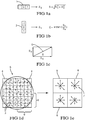
- Figure 1 shows basic operations performed for each pixel in the image to provide a HOG descriptor.
- the most common method is to apply the 1-D centered, point discrete derivative mask in one or both of the horizontal and vertical directions, see figure 1a and 1b , on each pixel of the image. This produces two dimensional components : y component, S y , and x -component S x . So in examples, this method requires filtering the color or intensity data of the image with the filter kernels 1 and 2 shown in figure 1a and 1b .
- the length of the vector is determined via Pythagoras theorem as shown in figure 1c .
- Figure 1d shows image of gradients 3 , with respect to pixels 4 in an area of an image 5 which is divided into a number of blocks 6, in the example 16 pixels per block. For each block 6, the descriptor 7 is shown in figure 1e .
- V A , V B and V C shown in Figure 2 . They are located on a X-Y plane, which is divided into 8 areas, A 1 ... A 8 (45° each). Each area is further divided into slots 9, whose number determines the approximation precision of the vector length; in the example of figure 2 the number of slots is 8 per area A i .
- the signs of the x and the y components determine in which quarter of the X-Y plane a given vector is located. These are denoted as North East NE (for x >0, y >0), North West NW ( x ⁇ 0, y >0), South East SE ( x ⁇ 0, y ⁇ 0) and South West SW ( x >0, y ⁇ 0) . Additionally, if the lengths of the components
- the V A vector is located in the A 1 , S 6 slot, V B vector in A 3 , S 6 slot, while vector V C in the A 4 , S 6 slot.
- the resultant vector is always located in the slot with the same number.
- To determine the length of the vector we only need to know the values of the
- the >> operation means shifting the bits to the right by a given number of positions.
- the shifting of bits to the right, for a binary numbers, is effectively dividing by 2 for each shift operation.
- the values of the b and s variables are constant for particular slot numbers independently on the area A i . However the values of b and s will be dependent on the number of slots and the slot numbers. These values (e.g. of -1, 0 and 1) can be found e.g. by a look up table referenced by the number of slots and the slot number.
- the slot number can be determined by the value of
- M max x y + s 0 ⁇ b 0 ⁇ min x y / 4 + s 1 ⁇ b 1 ⁇ ( min x y / 8 + s 2 ⁇ b 2 ⁇ ( min x y / 16
- equation (1) and (2) we consider only four components and, thus, only three b and three s variables, as it allows to obtain the precision that sufficient in the HOG algorithm. However, this formula can easily be extended to improve the accuracy by additional b and s variables that will further improve the precision.
- the approximation may be regarded as a polynomial type approximation.
- Shifting the bits is also a very simple operation, so the overall procedure described by equations above can be composed of simple logic operations. Particularly (in hardware implementation) it will lead to a very efficient solutions (very fast and consuming low hardware resources).
- signals are known, as they are outputs of simple finite impulse response (FIR) high-pass image filters (coefficients [-1, 0, 1] and [-1, 0, 1] T ).
- FIR finite impulse response
- approximation of the vector length is performed having only access to the
- the slot number As far as determining the slot number from values of
- the ranges may correspond to the particular column or row in the look up tables where the values of s and b are to be found. Preferably it is determined which of the values of
- the slots numbers are assigned to ranges falling between 0 and 1.
- slot 6 may be where the ratio is between 0.5 and 0.62; the number of ranges depends therefore on the number of slots in the methodology.
- the slot number may be regarded as "slot index value" and is determined from the values of
- the slot index number can be regarded as row or column or address of the look-up table.
- the slot number may be found from a floor or ceiling function.
- N S is the number of slots and can be regarded as a total slot number value.
- the div (divide) operation may be division without rest
- Figure 3 shows Tables 1 and 2 are provided example values of the b i and s i variables, for the cases of 8 and 16 slots respectively.
- the tables show/compare the computed vector lengths calculated for two cases: L2 (ideal - Euclidean distance, according to Pythagoras law) and APPR for the vector length calculated i.e. approximated according to methodology of the current invention (3bits /4bits). (approximated), as well as the discrepancies between both methods (an error introduced by the proposed method).
- Tables 1 and 2 present values of the coefficients b i and s i and the results for 8 and 16 slots, respectively.
- the values of the x and the y components have been selected in such a way that one of the components remains constant and is set to maximum value (normalized to 1), while the second one increases monotonically from 0 to 1.
- This scenario allows to cover all slots.
- the number of cases presented in tables 1 and 2 equals 9 (0 - 8) and 17 (0 - 16), respectively, as we perform calculations for such values of the x and y components, as the vectors were located on the borders between adjacent slots.
- the LUT can be simply realized by a combination of switches and logic gates.
- the b and the s coefficients in Tables 1 and 2 are examples only and the values of these coefficients and can be slightly modified if necessary (to obtain a different error spread).
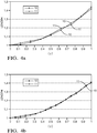
- Figure 4a and 4b shows compares plots of the length of the vector against
- Examples of the invention approximate the vector length with a precision exceeding 98%, which in fully sufficient for the HOG algorithm.
- Examples of the invention require only several basic operations, such as fixed-point summation / subtraction and shifting the bits. In case of a transistor-level implementation all operations required per calculation of a single vector length can be performed asynchronously during the time no greater than a few nanoseconds.
- aspects provide methods for the calculation of the vector length, suitable for fast hardware calculation of the Histogram-of-Oriented Gradients features several advantages over typical calculation methods based on Pythagoras low.
- the computation complexity is substantially smaller, as the squaring and square rooting operations have been omitted in this case. Examples can be implemented on various hardware platforms (also in embedded programmable platforms).
- the number of clock cycles required to calculate the vector length varies in-between 1 (asynchronous approach suitable in specialized chips) and 10 (depending on the required precision of the approximation). In comparison to even hundred clock cycles in typical methods the new method introduces a substantial improvement.
- the proposed method is in particular suitable for the HOG algorithm realized as a specialized chip or as embedded applications used in fast, real-time, processing of camera images in active safety algorithms used in automotive.
- aspects of the invention have particular application in automotive applications to detect and identify objects and obstacles such as other vehicles, pedestrians and such like.
- the method of HOG according to aspects of the invention is particularly useful in processing images from vehicle mounted cameras in order to characterize the vehicle environment.
- the processing of images allows detection of objects in the environment such as pedestrians, other vehicles, road signs, trees and such like.
- detections and identification of one or more classes of objects in images is useful in various automotive applications and systems such as collision avoidance systems, vehicles access and parking systems and such like.
Landscapes
- Engineering & Computer Science (AREA)
- Physics & Mathematics (AREA)
- General Physics & Mathematics (AREA)
- Multimedia (AREA)
- Theoretical Computer Science (AREA)
- Computer Vision & Pattern Recognition (AREA)
- Image Analysis (AREA)
Abstract
An image processing method adapted to detect and identify various classes of objects in images, which uses a Histogram of Gradients (HOG) methodology to determine gradient orientation in portions of an image; wherein in the HOG methodology, the length ( M ) of the gradient vectors associated with particular pixels are determined from pre-calculated components of the vector in x and y coordinates/directions ( x,y ), using the following formula: M = max x y + i = 0 k s i b i min x y / 2 i + 2 where max(| x |, | y |) is the absolute value of either said x or y components, whichever is the larger;
[min(| x |, | y |)/2 is the absolute value of either x or y components, whichever is the smaller; k is an integer value; and s i and b i are integers having values of 0, 1 or -1
Description
- The invention relates to a method of detecting and identifying various classes of objects in images, which uses the Histogram-of-Oriented Gradients (HOG) algorithm. It has particular application in automotive applications to detect and identify objects and obstacles such as other vehicles, pedestrians and such like.
- Histogram-of-Oriented Gradients (HOG) is an algorithm commonly used in image processing. The role of the algorithm is to detect and identify various classes of objects in images. The methodology determines gradient orientation in portions of an image. The idea behind the methodology is that local object appearance and shape within an image can be described by the distribution of intensity gradients or edge directions. In the methodology, an image is divided into cells, and for pixels within each cell, a histogram of gradient directions is compiled.
- The calculation scheme in this algorithm comprises several steps. In one of the initial steps, the image is filtered by the use of high-pass finite impulse response (FIR) gradient filters that return components (in the x and y coordinates) of gradient vectors associated with particular pixels.
- In the following steps, on the basis of the determined x and y components, the algorithm calculates the length of the vector, as well as its orientation in the 2-dimensional plane. Calculation of the vector length usually is performed using Pythagoras theorem which involves s squaring and rooting operations, while the second operation requires the use of the arctan function [atan(y/x)].
- As long as the HOG algorithm is used for an off-line (with no time constrains) analysis of the images there is only a limited concern regarding optimization of the calculations. A quite different situation arises in such cases in which the algorithm has to be used in real-time applications (e.g. implemented in embedded system or at the transistor level). In this situation the calculation time is one of the paramount concerns.
- The square rooting operation which is used to calculate the vector length in case of applying Pythagoras law is a time consuming operation. Depending on the processor and the required calculation precision, it may take up dozens even to a hundred clock cycles. The problem is especially visible in systems with limited computational resources, for example in custom designed digital circuit.
- It is an object of the invention to provide an efficient and very fast alternative method to determine vector length, assuming that the orientation of the vector (in which quarter of the Cartesian plane it is located) is known.
- In one aspect is provided an image processing method adapted to detect and identify various classes of objects in images, which uses a Histogram of Gradients (HOG) methodology to determine gradient orientation in portions of an image; wherein in the HOG methodology, the length (M) of the gradient vectors associated with particular pixels are determined from pre-calculated components of the vector in x and y coordinates/directions (x,y), using the following formula:

- where max(|x|, |y|) is the absolute value of either said x or y components, whichever is the larger;
- [min(|x|, |y|)/2 is the absolute value of either x or y components, whichever is the smaller;
- k is an integer value;
- and si and bi are integers having values of 0, 1 or -1.
- The values of b0, s1 and s0 are fixed integer values of 1.
- The values of bi may be either 0 or 1.
- The one or more values of bi and si may be determined from one or more look-up tables.
- The values of bi and si may be determined dependent on a slot index value, said slot index value being calculated form the values of |x| and |y| and a total slot number value Ns, where k=log2 N S.
- The Look-up Table may reference, for a particular total slot number value, the values of si and bi from slot index value.
- Said pre-calculated components of the vector in x and y coordinates/directions (x,y) may be output from finite impulse response (FIR) gradient filters.
- The present invention is now described by way of example with reference to the accompanying drawings in which:
-
Figure 1 shows basic operations performed for each pixel in the image to provide a HOG; -
Figure 2 illustrates an example of the methodology showing localization of the slots on the X-Y plane; -
Figure 3 shows tables T1 and T2 showing example values of coefficients si and bi , as well as the results and comparison with the idea (Pythagoras case) in the examples of 8 slot and 16 slots respectively; -
Figure 4a and 4b shows and compares plots of the length of the vector against |y| calculated by an ideal method using Pythagoras (L2 - Euclidean) and an approximated method according to examples of the invention, for the case of 8 and 16 slots respectively. -
Figure 1 shows basic operations performed for each pixel in the image to provide a HOG descriptor. The most common method is to apply the 1-D centered, point discrete derivative mask in one or both of the horizontal and vertical directions, seefigure 1a and 1b , on each pixel of the image. This produces two dimensional components : y component, Sy, and x-component Sx . So in examples, this method requires filtering the color or intensity data of the image with thefilter kernels figure 1a and 1b . In prior art methods the length of the vector is determined via Pythagoras theorem as shown infigure 1c . -
Figure 1d shows image ofgradients 3 , with respect topixels 4 in an area of animage 5 which is divided into a number ofblocks 6, in the example 16 pixels per block. For eachblock 6, thedescriptor 7 is shown infigure 1e . - In order to illustrate the methodology according to examples, let us consider example vectors V A, V B and V C, shown in
Figure 2 . They are located on a X-Y plane, which is divided into 8 areas, A 1 ... A 8 (45° each). Each area is further divided intoslots 9, whose number determines the approximation precision of the vector length; in the example offigure 2 the number of slots is 8 per area Ai . - The signs of the x and the y components determine in which quarter of the X-Y plane a given vector is located. These are denoted as North East NE (for x>0, y>0), North West NW (x<0, y>0), South East SE (x<0, y<0) and South West SW (x>0, y<0). Additionally, if the lengths of the components |x| and |y| are compared, it can be determined in which area, Ai , this vector is placed. The V A vector is located in the A 1, S 6 slot, V B vector in A 3, S 6 slot, while vector V C in the A 4, S 6 slot. Note that all three vectors are located in the slots with the same number (6 in this case). This is because |x A|- |y B|- |x C|, and |y A|= |x B|= |y C|. Note that x and y components are mixed in these formula. This is because |x A|> |y A| and |x C|> |y C|, while |y B|> |x B|.
- As can be seen, independently on the sign of the x and the y component, and independently whether |x|>|y| or vice versa, for given lengths of these components, the resultant vector is always located in the slot with the same number. To determine the length of the vector we only need to know the values of the |x| and |y| components, independently on their signs.
- As a result, for given values of the |x| and |y| components, the length M of any V vector can be approximated using the following formula (for the case with 8 slots per area A, shown in
Fig. 2 ):
- So the formula above may be written alternatively as:

- In equation (1) and (2) we consider only four components and, thus, only three b and three s variables, as it allows to obtain the precision that sufficient in the HOG algorithm. However, this formula can easily be extended to improve the accuracy by additional b and s variables that will further improve the precision. For an example case of 16 slots equation (1) would be expressed as:


- In general, every doubling of the number of the slots extends the formula above by one additional component, which is one of the advantages of the proposed algorithm. In general the calculation formula can be expressed as follows:


- Thus the approximation may be regarded as a polynomial type approximation.
- As mentioned values of the si variables have been specified as -1, 0, 1 to facilitate the formal description. In implementation both the s and the b variables may be simply single bits. The table below shows 4 possible states and action in the operation:
bi si Action Complexity 0 0 Do nothing 0 1 Do nothing 1 0 Reverse of the sign (negate and two's complement) of a given [ min(|x|,|y|)>>(i+2) ] term and then add Multiplication by s → negation of the bits 1 1 Add a given min(|x|,|y|)>>(i+2) Multiplication by b → simple logic AND operation - Shifting the bits is also a very simple operation, so the overall procedure described by equations above can be composed of simple logic operations. Particularly (in hardware implementation) it will lead to a very efficient solutions (very fast and consuming low hardware resources).
- The |x| and |y| signals are known, as they are outputs of simple finite impulse response (FIR) high-pass image filters (coefficients [-1, 0, 1] and [-1, 0, 1]T). In methodology as mention, approximation of the vector length is performed having only access to the |x| and the |y| values. If we determine the address of a given slot by means of a look up tables (e.g. see
figure 3 ) the values of the s and b shown are applied to the equation above. - As far as determining the slot number from values of |x| and |y|, this may be done by looking at the ratio of |x| and |y| and determining in which ranges of values the ratio, the range of values correspond to a slot number (index). The ranges may correspond to the particular column or row in the look up tables where the values of s and b are to be found. Preferably it is determined which of the values of |x| and |y| is the smallest and dividing this by the larger one. So if |x| is smaller than |y| the value of |x|/|y| is determined which will give a value between 0 and 1. The slots numbers are assigned to ranges falling between 0 and 1. So for
example slot 6 may be where the ratio is between 0.5 and 0.62; the number of ranges depends therefore on the number of slots in the methodology. In general the slot number may be regarded as "slot index value" and is determined from the values of |x| and |y| and the number of slots i.e. resolution. The slot index number can be regarded as row or column or address of the look-up table. - Thus the slot number may be found from a floor or ceiling function. In one example therefore, the position in the Look-up Table (LUT) (the slot number) from which given values of the si and bi coefficients are taken, may be calculated as follows:

- Again N S is the number of slots and can be regarded as a total slot number value.
- In this example shows calculations of the M value (signal) for number of slots (N S) = 8. If it is assumed that we use 8-bit numbers, and the values of |x| and |y| equal 100 and 35, respectively. The value of the ratio determined to find slot number is 35/100 which corresponds to slot
number 2 in table T1. So for number of slots (N S) = 8 the vector with such coordinates will be located in the 2nd slot (it is rounded to bottom value), so we take the s and b variables from the 3rd row of Table 1 offigure 3 . As a result:
- This can be compared to an ideal value of 105.95 i.e. sqrt(1002 + 352). The div (divide) operation may be division without rest
- Again an example calculations of the M value (signal) for number of slots (N S) = 8). |x| and |y| equal 210 and 170, respectively. This give a ratio of 170/210 and thus this determines we are in the 6th slot, so we take the values from the 7th row from Table 1, and:

- This can be compared to an ideal value of 270.19.
- In general the values in tables 1 and 2 are for the borders between adjacent slots, so for No.=0 we have the line below the first slot. Since we have 8 slots in Table 1 (16 in Table 2), we have 9 (17, respectively) values in the Table 1 (2). The 9th value will be used only if |x| = |y|.
-
Figure 3 shows Tables 1 and 2 are provided example values of the bi and si variables, for the cases of 8 and 16 slots respectively. In addition the tables show/compare the computed vector lengths calculated for two cases: L2 (ideal - Euclidean distance, according to Pythagoras law) and APPR for the vector length calculated i.e. approximated according to methodology of the current invention (3bits /4bits). (approximated), as well as the discrepancies between both methods (an error introduced by the proposed method). Thus Tables 1 and 2 present values of the coefficients bi and si and the results for 8 and 16 slots, respectively. For a better illustration, the values of the x and the y components have been selected in such a way that one of the components remains constant and is set to maximum value (normalized to 1), while the second one increases monotonically from 0 to 1. This scenario allows to cover all slots. The number of cases presented in tables 1 and 2 equals 9 (0 - 8) and 17 (0 - 16), respectively, as we perform calculations for such values of the x and y components, as the vectors were located on the borders between adjacent slots. - A consideration is determination of the values of the bi and si variables. As can be noticed the b 0 and s0 variables are always 1 (the same with s 1 variable), so they can be even omitted in equations above. In the case of remaining b and s variables, these may be determined by formulation. However such a formulation would increase the computational complexity, so in preferred methodology these variables (coefficients) are provided using a Look-up-Table (LUT). In programming languages the simples way is to use tables indexed by the slot number. In hardware implementation the structure of the LUT will depend on the type of the used hardware. In Field Programmable Gate Array (FPGA) again the LUT can be used. In case of transistor level implementation the LUT can be simply realized by a combination of switches and logic gates. The b and the s coefficients in Tables 1 and 2 are examples only and the values of these coefficients and can be slightly modified if necessary (to obtain a different error spread).
- The quality of the resultant approximation is illustrated also in
Figures 4a and 4b for the case of 8 and 16 slots, respectively. Increasing the number of slots from 8 to 16 allowed to improve the precision to the value > 99% (in most cases). This exceeds expectation for the HOG algorithm. -
Figure 4a and 4b shows compares plots of the length of the vector against |y| calculated by an he ideal method 10 (L2 - Euclidean) and an approximatedmethod 11 according to one aspect for the case of 8 and 16 slots respectively. Examples of the invention approximate the vector length with a precision exceeding 98%, which in fully sufficient for the HOG algorithm. Examples of the invention require only several basic operations, such as fixed-point summation / subtraction and shifting the bits. In case of a transistor-level implementation all operations required per calculation of a single vector length can be performed asynchronously during the time no greater than a few nanoseconds. Aspects provide methods for the calculation of the vector length, suitable for fast hardware calculation of the Histogram-of-Oriented Gradients features several advantages over typical calculation methods based on Pythagoras low. The computation complexity is substantially smaller, as the squaring and square rooting operations have been omitted in this case. Examples can be implemented on various hardware platforms (also in embedded programmable platforms). The number of clock cycles required to calculate the vector length varies in-between 1 (asynchronous approach suitable in specialized chips) and 10 (depending on the required precision of the approximation). In comparison to even hundred clock cycles in typical methods the new method introduces a substantial improvement. - The proposed method is in particular suitable for the HOG algorithm realized as a specialized chip or as embedded applications used in fast, real-time, processing of camera images in active safety algorithms used in automotive.
- Aspects of the invention have particular application in automotive applications to detect and identify objects and obstacles such as other vehicles, pedestrians and such like. The method of HOG according to aspects of the invention is particularly useful in processing images from vehicle mounted cameras in order to characterize the vehicle environment. In particular the processing of images allows detection of objects in the environment such as pedestrians, other vehicles, road signs, trees and such like. Such detections and identification of one or more classes of objects in images is useful in various automotive applications and systems such as collision avoidance systems, vehicles access and parking systems and such like.
Claims (7)
- An image processing method adapted to detect and identify various classes of objects in images, which uses a Histogram of Gradients (HOG) methodology to determine gradient orientation in portions of an image; wherein in the HOG methodology, the length (M) of the gradient vectors associated with particular pixels are determined from pre-calculated components of the vector in x and y coordinates/directions (x,y), using the following formula:
 where max(|x|, |y|) is the absolute value of either said x or y components, whichever is the larger;[min(|x|, |y|)/2 is the absolute value of either x or y components, whichever is the smaller;k is an integer value;and si and bi are integers having values of 0, 1 or -1.
 - A method as claimed in claim 1 wherein the values of b0, s1 and s0 are fixed integer values of 1.
- A method as claimed in claims 1 or 2 wherein the values of bi are either 0 or 1.
- A method as claimed in claims 1 to 3 where one or more values of bi and si are determined from one or more look-up tables.
- A method as claimed in claim 4 wherein the values of bi and si are determined dependent on a slot index value, said slot index value being calculated form the values of |x| and |y| and a total slot number value Ns, where k=log2 N S.
- A method as claimed in claim 5 wherein Look-up Table references, for a particular total slot number value, the values of si and bi from slot index value.
- A method as claimed in claims 1 to 6 wherein said pre-calculated components of the vector in x and y coordinates/directions (x,y) are output from finite impulse response (FIR) gradient filters.
Priority Applications (1)
| Application Number | Priority Date | Filing Date | Title |
|---|---|---|---|
| EP16205140.3A EP3336762A1 (en) | 2016-12-19 | 2016-12-19 | Method of estimation of histogram-of-oriented gradients |
Applications Claiming Priority (1)
| Application Number | Priority Date | Filing Date | Title |
|---|---|---|---|
| EP16205140.3A EP3336762A1 (en) | 2016-12-19 | 2016-12-19 | Method of estimation of histogram-of-oriented gradients |
Publications (1)
| Publication Number | Publication Date |
|---|---|
| EP3336762A1 true EP3336762A1 (en) | 2018-06-20 |
Family
ID=57754992
Family Applications (1)
| Application Number | Title | Priority Date | Filing Date |
|---|---|---|---|
| EP16205140.3A Withdrawn EP3336762A1 (en) | 2016-12-19 | 2016-12-19 | Method of estimation of histogram-of-oriented gradients |
Country Status (1)
| Country | Link |
|---|---|
| EP (1) | EP3336762A1 (en) |
Cited By (1)
| Publication number | Priority date | Publication date | Assignee | Title |
|---|---|---|---|---|
| CN110659650A (en) * | 2018-06-29 | 2020-01-07 | 株式会社电装 | Gradient direction calculating device |
Citations (1)
| Publication number | Priority date | Publication date | Assignee | Title |
|---|---|---|---|---|
| US20160203384A1 (en) * | 2015-01-08 | 2016-07-14 | Linear Algebra Technologies Limited | Hardware accelerator for histogram of gradients |
-
2016
- 2016-12-19 EP EP16205140.3A patent/EP3336762A1/en not_active Withdrawn
Patent Citations (1)
| Publication number | Priority date | Publication date | Assignee | Title |
|---|---|---|---|---|
| US20160203384A1 (en) * | 2015-01-08 | 2016-07-14 | Linear Algebra Technologies Limited | Hardware accelerator for histogram of gradients |
Non-Patent Citations (3)
| Title |
|---|
| CLAY S TURNER: "Fast Magnitude Calculation", 27 May 2009 (2009-05-27), XP055378111, Retrieved from the Internet <URL:http://www.claysturner.com/dsp/fastmagnitude.pdf> [retrieved on 20170601] * |
| LEUNG C ET AL: "Detection of edges of noisy images by 1-D and 2-D linear FIR digital filters", COMMUNICATIONS, COMPUTERS AND SIGNAL PROCESSING, 1993., IEEE PACIFIC R IM CONFERENCE ON VICTORIA, BC, CANADA 19-21 MAY 1, NEW YORK, NY, USA,IEEE, vol. 1, 19 May 1993 (1993-05-19), pages 228 - 231, XP010141622, ISBN: 978-0-7803-0971-5, DOI: 10.1109/PACRIM.1993.407182 * |
| MACIEJ CZYZAK ET AL: "FPGA REALIZATION OF AN IMPROVED ALPHA MAX PLUS BETA MIN ALGORITHM", 1 January 2014 (2014-01-01), XP055378076, Retrieved from the Internet <URL:http://www.iee.put.poznan.pl/wydawnictwa/wydawnictwaFiles/\2014\6_Academic Journals Poznan University of Technology_80\!151_19_Czyzak.pdf> [retrieved on 20170601] * |
Cited By (1)
| Publication number | Priority date | Publication date | Assignee | Title |
|---|---|---|---|---|
| CN110659650A (en) * | 2018-06-29 | 2020-01-07 | 株式会社电装 | Gradient direction calculating device |
Similar Documents
| Publication | Publication Date | Title |
|---|---|---|
| US11763568B2 (en) | Ground plane estimation in a computer vision system | |
| Muthalagu et al. | Lane detection technique based on perspective transformation and histogram analysis for self-driving cars | |
| EP2846306B1 (en) | Image processing apparatus for removing haze contained in still image and method thereof | |
| US20190318487A1 (en) | Method and apparatus for detection of false alarm obstacle | |
| EP0686942A2 (en) | Stereo matching method and disparity measuring method | |
| US6810145B2 (en) | Process for detecting a change of shot in a succession of video images | |
| US20110293191A1 (en) | Apparatus and method for extracting edges of image | |
| Mu et al. | Multiscale edge fusion for vehicle detection based on difference of Gaussian | |
| KR101483742B1 (en) | Lane Detection method for Advanced Vehicle | |
| US8823841B2 (en) | Method and apparatus for correcting for vignetting in an imaging system | |
| Wang et al. | An FPGA co-processor for adaptive lane departure warning system | |
| Choi et al. | Fog detection for de-fogging of road driving images | |
| Ijeri et al. | Traffic Control System Using Image Proccesing | |
| Priyanka et al. | Implementation of Sobel Edge Detection with Image Processing on FPGA | |
| Dev et al. | Steering angle estimation for autonomous vehicle | |
| Ozgunalp et al. | Lane detection by estimating and using restricted search space in Hough domain | |
| CN104616317A (en) | Video vehicle tracking validity checking method | |
| da Miranda Neto | Pearson's correlation coefficient: a more realistic threshold for applications on autonomous robotics | |
| Tran et al. | An adaptive method for lane marking detection based on HSI color model | |
| Halmaoui et al. | Contrast restoration of road images taken in foggy weather | |
| Agrawal et al. | Off-road lane detection using superpixel clustering and ransac curve fitting | |
| EP4471451A1 (en) | Method and apparatus for associating radar target with visual target, vehicle, and storage medium | |
| Han et al. | Color lane line detection using the Bhattacharyya distance | |
| US12347184B2 (en) | Method and apparatus for suppressing noise in 3D road surface reconstruction | |
| Raghavendra et al. | Time efficient design and FPGA implementation of distributed canny edge detector algorithm |
Legal Events
| Date | Code | Title | Description |
|---|---|---|---|
| PUAI | Public reference made under article 153(3) epc to a published international application that has entered the european phase |
Free format text: ORIGINAL CODE: 0009012 |
|
| AK | Designated contracting states |
Kind code of ref document: A1 Designated state(s): AL AT BE BG CH CY CZ DE DK EE ES FI FR GB GR HR HU IE IS IT LI LT LU LV MC MK MT NL NO PL PT RO RS SE SI SK SM TR |
|
| AX | Request for extension of the european patent |
Extension state: BA ME |
|
| RAP1 | Party data changed (applicant data changed or rights of an application transferred) |
Owner name: APTIV TECHNOLOGIES LIMITED |
|
| STAA | Information on the status of an ep patent application or granted ep patent |
Free format text: STATUS: THE APPLICATION IS DEEMED TO BE WITHDRAWN |
|
| 18D | Application deemed to be withdrawn |
Effective date: 20181221 |