EP3336609A1 - Powder supply device - Google Patents
Powder supply device Download PDFInfo
- Publication number
- EP3336609A1 EP3336609A1 EP17207950.1A EP17207950A EP3336609A1 EP 3336609 A1 EP3336609 A1 EP 3336609A1 EP 17207950 A EP17207950 A EP 17207950A EP 3336609 A1 EP3336609 A1 EP 3336609A1
- Authority
- EP
- European Patent Office
- Prior art keywords
- powder
- supply
- unit
- air blowing
- supply path
- Prior art date
- Legal status (The legal status is an assumption and is not a legal conclusion. Google has not performed a legal analysis and makes no representation as to the accuracy of the status listed.)
- Granted
Links
Images


Classifications
-
- G—PHYSICS
- G03—PHOTOGRAPHY; CINEMATOGRAPHY; ANALOGOUS TECHNIQUES USING WAVES OTHER THAN OPTICAL WAVES; ELECTROGRAPHY; HOLOGRAPHY
- G03G—ELECTROGRAPHY; ELECTROPHOTOGRAPHY; MAGNETOGRAPHY
- G03G15/00—Apparatus for electrographic processes using a charge pattern
- G03G15/06—Apparatus for electrographic processes using a charge pattern for developing
- G03G15/08—Apparatus for electrographic processes using a charge pattern for developing using a solid developer, e.g. powder developer
- G03G15/0822—Arrangements for preparing, mixing, supplying or dispensing developer
- G03G15/0877—Arrangements for metering and dispensing developer from a developer cartridge into the development unit
-
- G—PHYSICS
- G03—PHOTOGRAPHY; CINEMATOGRAPHY; ANALOGOUS TECHNIQUES USING WAVES OTHER THAN OPTICAL WAVES; ELECTROGRAPHY; HOLOGRAPHY
- G03G—ELECTROGRAPHY; ELECTROPHOTOGRAPHY; MAGNETOGRAPHY
- G03G15/00—Apparatus for electrographic processes using a charge pattern
- G03G15/06—Apparatus for electrographic processes using a charge pattern for developing
- G03G15/08—Apparatus for electrographic processes using a charge pattern for developing using a solid developer, e.g. powder developer
- G03G15/0894—Reconditioning of the developer unit, i.e. reusing or recycling parts of the unit, e.g. resealing of the unit before refilling with toner
-
- B—PERFORMING OPERATIONS; TRANSPORTING
- B65—CONVEYING; PACKING; STORING; HANDLING THIN OR FILAMENTARY MATERIAL
- B65B—MACHINES, APPARATUS OR DEVICES FOR, OR METHODS OF, PACKAGING ARTICLES OR MATERIALS; UNPACKING
- B65B1/00—Packaging fluent solid material, e.g. powders, granular or loose fibrous material, loose masses of small articles, in individual containers or receptacles, e.g. bags, sacks, boxes, cartons, cans, or jars
- B65B1/04—Methods of, or means for, filling the material into the containers or receptacles
- B65B1/16—Methods of, or means for, filling the material into the containers or receptacles by pneumatic means, e.g. by suction
-
- B—PERFORMING OPERATIONS; TRANSPORTING
- B65—CONVEYING; PACKING; STORING; HANDLING THIN OR FILAMENTARY MATERIAL
- B65B—MACHINES, APPARATUS OR DEVICES FOR, OR METHODS OF, PACKAGING ARTICLES OR MATERIALS; UNPACKING
- B65B1/00—Packaging fluent solid material, e.g. powders, granular or loose fibrous material, loose masses of small articles, in individual containers or receptacles, e.g. bags, sacks, boxes, cartons, cans, or jars
- B65B1/30—Devices or methods for controlling or determining the quantity or quality or the material fed or filled
- B65B1/32—Devices or methods for controlling or determining the quantity or quality or the material fed or filled by weighing
- B65B1/34—Adjusting weight by trickle feed
-
- B—PERFORMING OPERATIONS; TRANSPORTING
- B65—CONVEYING; PACKING; STORING; HANDLING THIN OR FILAMENTARY MATERIAL
- B65B—MACHINES, APPARATUS OR DEVICES FOR, OR METHODS OF, PACKAGING ARTICLES OR MATERIALS; UNPACKING
- B65B39/00—Nozzles, funnels or guides for introducing articles or materials into containers or wrappers
- B65B39/007—Guides or funnels for introducing articles into containers or wrappers
Definitions
- the present invention relates to a powder supply device which controls the flow rate of a powder to supply the powder.
- Japanese Patent Application Laid-Open Publication No. 2016-172566 describes a toner filling apparatus which executes toner draw-in filling control for the purpose of improving the filling speed and the filling density while maintaining the toner properties, the toner draw-in filling control being control in which when a control unit fluidizes a toner in a filling tank by a toner fluidizing unit and opens a toner filling path by a filling path opening/closing unit so as to load the fluidized toner from the filling tank to a toner container, the control unit reduces a pressure in the toner container to a negative pressure by a container room sucking unit so as to draw in the toner from the filling tank into the toner container by the negative pressure.
- Japanese Patent Application Laid-Open Publication No. 2016-172566 also describes regulating a powder flow path cross-sectional area to a comparatively small size, opening the powder filling path by the filling path opening/closing unit so as to fill the powder container with the powder through the powder filling path until a measured value by a measuring unit reaches a target value.
- Japanese Patent Application Laid-Open Publication No. 2016-172566 also describes closing the powder filling path by sucking air from a mixture of the powder and air in the powder supply path through a filter member to temporarily aggregate the residual powder, in which the filter member is impermeable to the powder but permeable to air.
- the present invention has been made in consideration of the above problems in the conventional techniques, and an object of the present invention is to accurately control the supplied powder flow rate without depending on the powder flow path cross-sectional area in the powder supply device which controls the powder flow rate to supply the powder.
- a powder supply device reflecting one aspect of the present invention ejects a powder stored in a tank from a predetermined ejection port to supply the powder
- the powder supply device including: a powder fluidizing unit which blows air into the powder in the tank to fluidize the powder; a powder supply path forming member which forms a powder supply path in which one end is the ejection port and the other end is an inflow port connected to the tank, wherein the powder in the tank which is fluidized by the powder fluidizing unit flows into the inflow port so as to be ejected from the ejection port through the powder supply path; an air blowing unit which blows air toward the powder that is about to flow into the inflow port; and a control unit, wherein the control unit is capable of executing supply flow rate control of controlling a powder ejection amount from the ejection port according to an air blowing amount by the air blowing unit by controlling the air blowing amount.
- a powder supply device 100 in the embodiment includes a tank 10, a powder supply path forming member 20, a powder fluidizing unit 30, an air blowing unit 40 and a control unit 1.
- the block diagram of the control system of the powder supply device 100 in the embodiment is shown in FIG. 3 .
- the powder P which is a supply target is stored in the tank 10.
- the powder P is a toner, for example.
- the powder P is replenished to a powder storing space 11 of the tank 10 through a supply port that is disposed in a lateral portion or the like of the tank 10.
- the powder supply path forming member 20 is a cylindrical body which is provided in the lower end of the tank 10.
- the powder supply path forming member 20 forms a powder supply path 21 in which one end is an ejection port 21a and the other end is an inflow port 21b that is connected to the powder storing space 11.
- the powder supply path forming member 20 can have a configuration in which the inflow port 21b is disposed upward in a vertical direction as shown in FIG. 1 , a configuration in which the inflow port 21b is disposed horizontally as shown in FIG. 2 , and such like. Though a general configuration disposes the ejection port 21a downward in the vertical direction, the ejection port 21a may be disposed in an appropriate direction according to the convenience of the receiving side of the supply. Accordingly, there is used a straight powder supply path forming member 20 as shown in FIG. 1 , an L-shaped powder supply path forming member 20 as shown in FIG. 2 , or the like as needed.
- the powder fluidizing unit 30 includes a filter member that is disposed on a wall defining the powder storing space 11, an air supply path for blowing air to the powder P in the tank 10 through the filter member so as to fluidize the powder P, a control valve and such like.
- the filter member is impermeable to the powder P but permeable to air, which is made of a porous material or the like.
- the powder supply device 100 causes the powder P in the tank 10 fluidized by the powder fluidizing unit 30 to flow into the inflow port 21b and ejects the powder P from the ejection port 21a through the powder supply path 21 to supply the powder P.
- the air blowing unit 40 (40A, 40B) is configured by including an air blowing tube 41 (41A, 41B), an air supply path for blowing air toward the powder flowing into the inflow port 21b through the air blowing tube 41 (41A, 41B), a control valve 42 (42A, 42B) and such like.
- One or both of the first type of air blowing unit 40A and the second type of air blowing unit 40B are used.
- the air blowing tube 41A is connected to the powder supply path 21, air reaches the inflow port 21b through a part of the powder supply path 21 including the inflow port 21b, and the air further reaches the immediate anterior region 11a to the inflow port 21b in the powder storing space 11. That is, the powder supply path 21 is used as an air path to the inflow port 21b. Accordingly, in a case of the first type of air blowing unit 40A, air is blown from inside the powder supply path 21 to the inflow port 21b and further to the immediate anterior region 11a.
- connection angle ⁇ of the air blowing tube 41A with respect to the axis direction of the inflow port 21b is arbitrary and sufficient as long as the powder ejection amount is suppressed.
- the air blowing unit 40A has a capacity capable of blowing an air blowing amount which makes the powder ejection amount from the ejection port 21a be zero.
- connection angle ⁇ of the air blowing tube 41A with respect to the axis direction of the inflow port 21b is 180 degrees.
- the powder supply path 21 is a horizontal path from the inflow port 21b to a predetermined dimension.
- the second type of air blowing unit 40B does not use the powder supply path 21 as an air path to the inflow port 21b, and a blowing port 41B1 of the air blowing tube 41B is disposed in the powder storing space 11.
- the blowing port 41B1 is directed toward the immediate anterior region 11a, and an appropriate nozzle shape is applied.
- the blowing angle ⁇ with respect to the axis direction of the inflow port 21b is arbitrary and sufficient as long as the powder ejection amount is suppressed.
- the air blowing unit 40B has a capacity capable of blowing an air blowing amount which makes the powder ejection amount from the ejection port 21a be zero.
- the air blown into the powder storing space 11 from the inflow port 21b also has an action of fluidizing the powder P, and the air blowing unit 40 is also a powder fluidizing unit. Accordingly, there can be an embodiment of using only the air blowing unit 40 as the powder fluidizing unit.
- the control unit 1 controls the powder fluidizing unit 30, the air blowing unit 40 and such like.
- a computer provided with a processor, a storage device and such like is used.
- the processor executes a program stored in the storage device, and thereby achieves a function of executing after-mentioned control contents of powder supply.
- the control unit 1 is capable of setting a target value of the supply amount of the powder P.
- a powder supply device 101 in the embodiment has a configuration similar to that of the powder supply device 100 in the first embodiment except that a supply path opening/closing unit 50 is further added to the configuration of the first embodiment.
- the block diagram of the control system of the powder supply device 101 in the embodiment is shown in FIG. 7 .
- the supply path opening/closing unit 50 (50A, 50B) in the second embodiment of the present invention is configured by including a filter member 51 (51A, 51B), an air intake path, a control valve 52 (52A, 52B) and an air intake tube 53 (53A, 53B).
- the filter member 51 is impermeable to the powder P but permeable to air, which is made of a porous material or the like.
- the supply path opening/closing unit 50 closes the powder filling path 21 by sucking air from a mixture of the powder P and air in the powder supply path 21 through a filter member 51 to temporarily aggregate the residual powder.
- the aggregated powder JP JP1, JP2
- JP1, JP2 is shown in the drawings. Thereafter, the supply path opening/closing unit 50 opens the powder supply path 21 by stopping the suction. By controlling the suction force, it is possible to control the size of the aggregated powder JP, that is, the opening degree of the powder supply path 21.
- the first type of supply path opening/closing unit 50A is provided so as to make the aggregated powder JP1 on a side closer to the ejection port 21a than a junction 21c of the powder supply path 21 and the air flow path by the air blowing unit 40A.
- An air intake tube 53A is connected to the powder supply path forming member 20.
- the second type of supply path opening/closing unit 50B is provided so as to make the aggregated powder JP2 on a side closer to the inflow port 21b than the junction 21c, and an air intake tube 53B is connected to the powder supply path forming member 20.
- One or both of the first type of supply path opening/closing unit 50A and the second type of supply path opening/closing unit 50B are used.
- FIG. 5 shows the second embodiment of the present invention in which a measuring unit 90 is used.
- a measuring unit 90 a digital scale is used.
- the measuring unit 90 measures the weight of the container 91 and the weight of the powder in the container 91.
- the measuring unit 90 measures the powder ejected from the ejection port 21a, and inputs the measurement value to the control unit 1.
- the measuring unit 90 may be also used as needed in the first and third embodiments.
- the connection angle ⁇ of the air blowing tube 41A with respect to the axial direction of the inflow port 21b is 180 degrees.
- the powder supply path 21 is a horizontal path from the inflow port 21b to a predetermined dimension.
- the powder supply path 21 is a rising slope path from the inflow port 21b to a predetermined dimension.
- the powder supply path 21 from the inflow port 21b to an appropriate dimension be a horizontal path as shown in FIGS. 4 and 5 or a rising slope path as shown in FIG. 6 , such a bad influence can be reduced and the powder supply can be stopped by the supply path opening/closing unit 50 accurately.
- the powder supply device 102 in the embodiment has a configuration similar to that of the powder supply device 101 in the second embodiment except that the powder supply device 102 in the third embodiment has the following configuration.
- an air blowing tube 41C is connected to the air intake tube 53A. That is, the air intake path of the first type of supply path opening/closing unit 50A and the air blowing path of the third type of air blowing unit 40C are a common path immediately anterior to the powder supply path 21.
- an air blowing tube 41D is connected to the air intake tube 53B. That is, the air intake path of the second type of supply path opening/closing unit 50B and the air blowing path of the fourth type of air blowing unit 40D are a common path immediately anterior to the powder supply path 21.
- One or both of the third type of air blowing unit 40C and the fourth type of air blowing unit 40D are used.
- the block diagram of a control system of the powder supply device 102 in the embodiment is similar to FIG. 7 .
- control contents of the powder supply by the above-mentioned powder supply devices 100 to 102 will be described with reference to the flowchart of FIG. 9 .
- a target value of the supply amount of the powder P has been already set.
- control unit 1 executes preparation control as in the following manner.
- step S1 the control unit 1 controls the powder fluidizing unit 30 to blow air for fluidizing the powder P into the tank 10 (step S2), and replenishes the powder P to a predetermined level in the tank 10 (step S3).
- the control unit 1 stops the supply by controlling the air blowing unit 40 to blow the air blowing amount which makes the powder ejection amount from the ejection port 21a be zero (The control is also possible in the second and third embodiments).
- the control unit 1 stops the supply by controlling the air blowing amount by the air blowing unit 40 to zero, and at the same time, further controls the supply path opening/closing unit 50 to make the aggregated powder JP.
- the control unit 1 stops the supply by controlling the air blowing amount by the air blowing unit 40 to zero and making the aggregated powder JP with the suction force by the supply path opening/closing unit 50.
- control unit 1 executes the supply control as in the following manner.
- the control unit 1 starts supply of the powder P (step S4).
- the control unit 1 controls the air blowing unit 40 to decelerate the air blowing amount or make the air blowing amount be zero, and thereby starts the supply.
- the control unit 1 controls air blowing by the air blowing unit 40 at the same time as the control of the supply path opening/closing unit 50 to reduce or eliminate the aggregated powder JP, and thereby starts the supply.
- the control unit 1 controls the air blowing amount by the air blowing unit 40 to reduce or eliminate the aggregated powder JP, and thereby starts the supply.
- control unit 1 causes the air blowing unit 40 to blow out strong air and blow off the aggregated powder JP, and thereby starts supply at a full supply flow rate at once.
- the supply is performed at a high supply flow rate for a while from the start of supply (step S5).
- control unit 1 decelerates the powder ejection amount from the ejection port 21a for deceleration stop when it is determined that the measurement value of the measuring unit 90 reaches a predetermined threshold lower than the target value (steps S61 and S62).
- Step S61 can be performed in any of the first to third embodiments.
- the control unit 1 increases the air blowing amount by the air blowing unit 40, and thereby decelerates the powder ejection amount from the ejection port 21a.
- the powder ejection amount may be decelerated in multiple steps or continuously.
- Step S62 can be performed in the second and third embodiments.
- the control unit 1 increases the size of the aggregated powder JP, that is, lowers the opening degree of the powder supply path 21, and thereby decelerates the powder ejection amount from the ejection port 21a.
- the powder ejection amount may be decelerated in multiple steps or continuously.
- step S63 the above-mentioned control of decelerating the powder ejection amount is not performed.
- control unit 1 executes the supply stop control as in a following manner.
- control unit 1 stops the supply (steps S71, S72, S73 and S74).
- step S71 the control unit 1 controls the air blowing unit 40 to blow out the air blowing amount to make the powder ejection amount from the ejection port 21a be zero, and thereby stops the supply.
- Step S71 can also be performed in the second and third embodiments.
- Step S72 can be performed in the second and third embodiments.
- step S72 the control unit 1 controls the supply path opening/closing unit 50 to make the aggregated powder JP, and stops the supply.
- step S72 the control unit 1 controls the air blowing amount by the air blowing unit 40 to zero and makes the aggregated powder JP with a suction force by the supply path opening/closing unit 50, and thereby stops the supply.
- steps S73 and S74 can be performed in the second and third embodiments.
- step S73 the control unit 1 controls the air blowing unit 40 to blow out the air blowing amount to make the powder ejection amount from the ejection port 21a be zero, and thereby stops the supply.
- step S74 the control unit 1 controls the supply path opening/closing unit 50 to make the aggregated powder JP, and thereby stops the supply.
- step S74 the control unit 1 stops air blowing by the air blowing unit 40, starts suction by the supply path opening/closing unit 50 to make the aggregated powder JP at the same time or before the stop of the air blowing, and closes the powder supply path 21, in order to maintain the supply stop state.
- step S73 the control unit 1 controls the air blowing unit 40 to blow out the air blowing amount to make the powder ejection amount from the ejection port 21a be zero, and thereby stops the supply.
- step S74 the control unit 1 stops the air blowing by the air blowing unit 40 to make the aggregated powder JP with a suction force by the supply path opening/closing unit 50, and thereby stops the supply.
- step S61, S62 or S63 is selected to be executed.
- step S71, S72 or S73 is selected to be executed and step S74 is executed after step S73 to stop the supply. Then, the processing can return to step S1.
- the powder P stored in the tank 10 is ejected to be supplied from the ejection port 21a, the inflow amount is suppressed by controlling the blowing amount of the air blown toward the powder P which is about to flow into the inflow port 21b to the powder supply path 21 from the tank 10, and the powder ejection amount from the ejection port 21a is controlled.
- the supplied powder flow rate can be accurately controlled without depending on the powder flow path cross-sectional area.
Landscapes
- Engineering & Computer Science (AREA)
- Mechanical Engineering (AREA)
- Physics & Mathematics (AREA)
- General Physics & Mathematics (AREA)
- Life Sciences & Earth Sciences (AREA)
- Sustainable Development (AREA)
- Quality & Reliability (AREA)
- Filling Or Emptying Of Bunkers, Hoppers, And Tanks (AREA)
- Air Transport Of Granular Materials (AREA)
- Supply Of Fluid Materials To The Packaging Location (AREA)
- Basic Packing Technique (AREA)
Abstract
Description
- The present invention relates to a powder supply device which controls the flow rate of a powder to supply the powder.
- There have been conventionally used powder supply devices which supply predetermined amounts of powders such as toners to the supply destinations such as containers.
- Japanese Patent Application Laid-Open Publication No.
2016-172566 - Japanese Patent Application Laid-Open Publication No.
2016-172566 - Japanese Patent Application Laid-Open Publication No.
2016-172566 - However, in the invention described in Japanese Patent Application Laid-Open Publication No.
2016-172566 - The present invention has been made in consideration of the above problems in the conventional techniques, and an object of the present invention is to accurately control the supplied powder flow rate without depending on the powder flow path cross-sectional area in the powder supply device which controls the powder flow rate to supply the powder.
- To achieve at least one of the abovementioned objects, according to an aspect of the present invention, a powder supply device reflecting one aspect of the present invention ejects a powder stored in a tank from a predetermined ejection port to supply the powder, the powder supply device including: a powder fluidizing unit which blows air into the powder in the tank to fluidize the powder; a powder supply path forming member which forms a powder supply path in which one end is the ejection port and the other end is an inflow port connected to the tank, wherein the powder in the tank which is fluidized by the powder fluidizing unit flows into the inflow port so as to be ejected from the ejection port through the powder supply path; an air blowing unit which blows air toward the powder that is about to flow into the inflow port; and a control unit, wherein the control unit is capable of executing supply flow rate control of controlling a powder ejection amount from the ejection port according to an air blowing amount by the air blowing unit by controlling the air blowing amount.
- The advantages and features provided by one or more embodiments of the invention will become more fully understood from the detailed description given hereinafter and the appended drawings which are given by way of illustration only, and thus are not intended as a definition of the limits of the present invention, and wherein:
-
FIG. 1 is a front schematic view of a powder supply device in a first embodiment of the present invention; -
FIG. 2 is a front schematic view of a powder supply device in the first embodiment of the present invention, showing a modification example ofFIG. 1 ; -
FIG. 3 is a block diagram of a control system of the powder supply device in the first embodiment of the present invention; -
FIG. 4 is a front schematic view of a powder supply device in a second embodiment of the present invention; -
FIG. 5 is a front schematic view of a powder supply device in the second embodiment of the present invention, adding a measuring unit toFIG. 4 ; -
FIG. 6 is a front schematic view of a powder supply device in the second embodiment of the present invention, changing an angle of an inflow port inFIG. 4 ; -
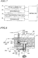
FIG. 7 is a block diagram of a control system of a powder supply device in second and third embodiments of the present invention; -
FIG. 8 is a front schematic view of a powder supply device in the third embodiment of the present invention; and -
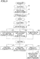
FIG. 9 is a flowchart of powder supply control in the embodiments of the present invention. - Hereinafter, one or more embodiments of the present invention will be described with reference to the drawings. However, the scope of the invention is not limited to the disclosed embodiments.
- First, a powder supply device in a first embodiment of the present invention will be described.
- As shown in
FIGS. 1, 2 and3 , apowder supply device 100 in the embodiment includes atank 10, a powder supplypath forming member 20, a powder fluidizingunit 30, anair blowing unit 40 and a control unit 1. The block diagram of the control system of thepowder supply device 100 in the embodiment is shown inFIG. 3 . - The powder P which is a supply target is stored in the
tank 10. The powder P is a toner, for example. Though not shown in the drawings, the powder P is replenished to apowder storing space 11 of thetank 10 through a supply port that is disposed in a lateral portion or the like of thetank 10. - The powder supply
path forming member 20 is a cylindrical body which is provided in the lower end of thetank 10. The powder supplypath forming member 20 forms apowder supply path 21 in which one end is anejection port 21a and the other end is aninflow port 21b that is connected to thepowder storing space 11. - The powder supply
path forming member 20 can have a configuration in which theinflow port 21b is disposed upward in a vertical direction as shown inFIG. 1 , a configuration in which theinflow port 21b is disposed horizontally as shown inFIG. 2 , and such like. Though a general configuration disposes theejection port 21a downward in the vertical direction, theejection port 21a may be disposed in an appropriate direction according to the convenience of the receiving side of the supply. Accordingly, there is used a straight powder supplypath forming member 20 as shown inFIG. 1 , an L-shaped powder supplypath forming member 20 as shown inFIG. 2 , or the like as needed. - The powder fluidizing
unit 30 includes a filter member that is disposed on a wall defining thepowder storing space 11, an air supply path for blowing air to the powder P in thetank 10 through the filter member so as to fluidize the powder P, a control valve and such like. The filter member is impermeable to the powder P but permeable to air, which is made of a porous material or the like. - The
powder supply device 100 causes the powder P in thetank 10 fluidized by the powder fluidizingunit 30 to flow into theinflow port 21b and ejects the powder P from theejection port 21a through thepowder supply path 21 to supply the powder P. - The air blowing unit 40 (40A, 40B) is configured by including an air blowing tube 41 (41A, 41B), an air supply path for blowing air toward the powder flowing into the
inflow port 21b through the air blowing tube 41 (41A, 41B), a control valve 42 (42A, 42B) and such like. - One or both of the first type of
air blowing unit 40A and the second type ofair blowing unit 40B are used. - In the first type of
air blowing unit 40A, theair blowing tube 41A is connected to thepowder supply path 21, air reaches theinflow port 21b through a part of thepowder supply path 21 including theinflow port 21b, and the air further reaches the immediateanterior region 11a to theinflow port 21b in thepowder storing space 11. That is, thepowder supply path 21 is used as an air path to theinflow port 21b. Accordingly, in a case of the first type ofair blowing unit 40A, air is blown from inside thepowder supply path 21 to theinflow port 21b and further to the immediateanterior region 11a. - By such a configuration, air is blown toward the powder P which is about to flow into the
inflow port 21b. As the air blowing amount increases, the inflow amount of the powder P to theinflow port 21b, that is, the powder ejection amount from theejection port 21a is suppressed. That is, the air blown from theair blowing tube 41A is a resistance to the powder P which is about to flow into theinflow port 21b. - The connection angle α of the
air blowing tube 41A with respect to the axis direction of theinflow port 21b is arbitrary and sufficient as long as the powder ejection amount is suppressed. In the embodiment, the air blowingunit 40A has a capacity capable of blowing an air blowing amount which makes the powder ejection amount from theejection port 21a be zero. - In the configuration shown in
FIG. 2 , the connection angle α of theair blowing tube 41A with respect to the axis direction of theinflow port 21b is 180 degrees. In the configuration shown inFIG. 2 , thepowder supply path 21 is a horizontal path from theinflow port 21b to a predetermined dimension. - The second type of
air blowing unit 40B does not use thepowder supply path 21 as an air path to theinflow port 21b, and a blowing port 41B1 of theair blowing tube 41B is disposed in thepowder storing space 11. In this case, the blowing port 41B1 is directed toward the immediateanterior region 11a, and an appropriate nozzle shape is applied. - By such a configuration, air is blown toward the powder P which is about to flow into the
inflow port 21b. As the air blowing amount increases, the inflow amount of the powder P to theinflow port 21b, that is, the powder ejection amount from theejection port 21a is suppressed. That is, the air blown from theair blowing tube 41B is a resistance to the powder P which is about to flow into theinflow port 21b. - The blowing angle β with respect to the axis direction of the
inflow port 21b is arbitrary and sufficient as long as the powder ejection amount is suppressed. In the embodiment, the air blowingunit 40B has a capacity capable of blowing an air blowing amount which makes the powder ejection amount from theejection port 21a be zero. - The air blown into the
powder storing space 11 from theinflow port 21b also has an action of fluidizing the powder P, and theair blowing unit 40 is also a powder fluidizing unit. Accordingly, there can be an embodiment of using only theair blowing unit 40 as the powder fluidizing unit. - The control unit 1 controls the powder fluidizing
unit 30, theair blowing unit 40 and such like. As the control unit 1, a computer provided with a processor, a storage device and such like is used. The processor executes a program stored in the storage device, and thereby achieves a function of executing after-mentioned control contents of powder supply. The control unit 1 is capable of setting a target value of the supply amount of the powder P. - The control contents of powder supply in the
powder supply device 100 in the embodiment will be described later. - Next, a powder supply device in a second embodiment of the present invention will be described.
- As shown in
FIGS. 4 ,5 ,6 and7 , apowder supply device 101 in the embodiment has a configuration similar to that of thepowder supply device 100 in the first embodiment except that a supply path opening/closing unit 50 is further added to the configuration of the first embodiment. The block diagram of the control system of thepowder supply device 101 in the embodiment is shown inFIG. 7 . - The supply path opening/closing unit 50 (50A, 50B) in the second embodiment of the present invention is configured by including a filter member 51 (51A, 51B), an air intake path, a control valve 52 (52A, 52B) and an air intake tube 53 (53A, 53B).
- The filter member 51 is impermeable to the powder P but permeable to air, which is made of a porous material or the like.
The supply path opening/closing unit 50 closes thepowder filling path 21 by sucking air from a mixture of the powder P and air in thepowder supply path 21 through a filter member 51 to temporarily aggregate the residual powder. The aggregated powder JP (JP1, JP2) is shown in the drawings. Thereafter, the supply path opening/closing unit 50 opens thepowder supply path 21 by stopping the suction. By controlling the suction force, it is possible to control the size of the aggregated powder JP, that is, the opening degree of thepowder supply path 21. - The first type of supply path opening/
closing unit 50A is provided so as to make the aggregated powder JP1 on a side closer to theejection port 21a than ajunction 21c of thepowder supply path 21 and the air flow path by theair blowing unit 40A. Anair intake tube 53A is connected to the powder supplypath forming member 20. - The second type of supply path opening/
closing unit 50B is provided so as to make the aggregated powder JP2 on a side closer to theinflow port 21b than thejunction 21c, and anair intake tube 53B is connected to the powder supplypath forming member 20. One or both of the first type of supply path opening/closing unit 50A and the second type of supply path opening/closing unit 50B are used. -
FIG. 5 shows the second embodiment of the present invention in which a measuringunit 90 is used. As the measuringunit 90, a digital scale is used. The measuringunit 90 measures the weight of thecontainer 91 and the weight of the powder in thecontainer 91. The measuringunit 90 measures the powder ejected from theejection port 21a, and inputs the measurement value to the control unit 1. The measuringunit 90 may be also used as needed in the first and third embodiments. - In the configurations shown in
FIGS. 4 ,5 and 6 , the connection angle α of theair blowing tube 41A with respect to the axial direction of theinflow port 21b is 180 degrees. In the configurations shown inFIGS. 4 and5 , thepowder supply path 21 is a horizontal path from theinflow port 21b to a predetermined dimension. In the configuration shown inFIG. 6 , thepowder supply path 21 is a rising slope path from theinflow port 21b to a predetermined dimension. In a case of closing thepowder supply path 21 by the aggregated powder JP, when theinflow port 21b is directed upward as shown inFIG. 1 , the accuracy of stopping the powder supply by the supply path opening/closing unit 50 is worse due to the influence of the powder's own weight. By making thepowder supply path 21 from theinflow port 21b to an appropriate dimension be a horizontal path as shown inFIGS. 4 and5 or a rising slope path as shown inFIG. 6 , such a bad influence can be reduced and the powder supply can be stopped by the supply path opening/closing unit 50 accurately. - The control contents of the powder supply in the
powder supply device 101 in the embodiment will be described later. - Next, the powder supply device in the third embodiment of the present invention will be described.
- As shown in
FIG. 8 , thepowder supply device 102 in the embodiment has a configuration similar to that of thepowder supply device 101 in the second embodiment except that thepowder supply device 102 in the third embodiment has the following configuration. - In a third type of
air blowing unit 40C, an air blowing tube 41C is connected to theair intake tube 53A. That is, the air intake path of the first type of supply path opening/closing unit 50A and the air blowing path of the third type ofair blowing unit 40C are a common path immediately anterior to thepowder supply path 21. - In a state in which a constant suction force is applied by the first type of supply path opening/
closing unit 50A, by controlling the air blowing amount by the third type ofair blowing unit 40C, it is possible to control the size of the aggregated powder JP1, that is, the opening degree of thepowder supply path 21. By controlling the air blowing amount in a range of remaining after offset of the suction force by the first type of supply path opening/closing unit 50A, air is blown from inside thepowder supply path 21 to theinflow port 21b and further to the immediateanterior region 11a similarly to the first embodiment, and the powder ejection amount from theejection port 21a can be controlled. - In a fourth type of
air blowing unit 40D, anair blowing tube 41D is connected to theair intake tube 53B. That is, the air intake path of the second type of supply path opening/closing unit 50B and the air blowing path of the fourth type ofair blowing unit 40D are a common path immediately anterior to thepowder supply path 21. - In a state in which a constant suction force is applied by the second type of supply path opening/
closing unit 50B, by controlling the air blowing amount by the fourth type ofair blowing unit 40D, it is possible to control the size of the aggregated powder JP2, that is, the opening degree of thepowder supply path 21. By controlling the air blowing amount in a range remaining after offset of the suction force by the second type of supply path opening/closing unit 50B, air is blown from inside thepowder supply path 21 to theinflow port 21b and further to the immediateanterior region 11a similarly to the first embodiment, and the powder ejection amount from theejection port 21a can be controlled. - One or both of the third type of
air blowing unit 40C and the fourth type ofair blowing unit 40D are used. The block diagram of a control system of thepowder supply device 102 in the embodiment is similar toFIG. 7 . - The control contents of powder supply in the
powder supply device 102 in the embodiment will be described later. - Next, the control contents of the powder supply by the above-mentioned
powder supply devices 100 to 102 will be described with reference to the flowchart ofFIG. 9 . In the control unit 1, a target value of the supply amount of the powder P has been already set. - First, the control unit 1 executes preparation control as in the following manner.
- In a state of supply stop (step S1), the control unit 1 controls the
powder fluidizing unit 30 to blow air for fluidizing the powder P into the tank 10 (step S2), and replenishes the powder P to a predetermined level in the tank 10 (step S3). Here, in the first embodiment, the control unit 1 stops the supply by controlling theair blowing unit 40 to blow the air blowing amount which makes the powder ejection amount from theejection port 21a be zero (The control is also possible in the second and third embodiments). In the second embodiment, the control unit 1 stops the supply by controlling the air blowing amount by theair blowing unit 40 to zero, and at the same time, further controls the supply path opening/closing unit 50 to make the aggregated powder JP. In the third embodiment, the control unit 1 stops the supply by controlling the air blowing amount by theair blowing unit 40 to zero and making the aggregated powder JP with the suction force by the supply path opening/closing unit 50. - Next, the control unit 1 executes the supply control as in the following manner.
- The control unit 1 starts supply of the powder P (step S4). Here, in the first embodiment, the control unit 1 controls the
air blowing unit 40 to decelerate the air blowing amount or make the air blowing amount be zero, and thereby starts the supply. In the second embodiment, the control unit 1 controls air blowing by theair blowing unit 40 at the same time as the control of the supply path opening/closing unit 50 to reduce or eliminate the aggregated powder JP, and thereby starts the supply. In the third embodiment, the control unit 1 controls the air blowing amount by theair blowing unit 40 to reduce or eliminate the aggregated powder JP, and thereby starts the supply. - In the second and third embodiments, the control unit 1 causes the
air blowing unit 40 to blow out strong air and blow off the aggregated powder JP, and thereby starts supply at a full supply flow rate at once. - In order to increase the supply speed, the supply is performed at a high supply flow rate for a while from the start of supply (step S5).
- Next, the control unit 1 decelerates the powder ejection amount from the
ejection port 21a for deceleration stop when it is determined that the measurement value of the measuringunit 90 reaches a predetermined threshold lower than the target value (steps S61 and S62). - Step S61 can be performed in any of the first to third embodiments. In step S61, the control unit 1 increases the air blowing amount by the
air blowing unit 40, and thereby decelerates the powder ejection amount from theejection port 21a. The powder ejection amount may be decelerated in multiple steps or continuously. - Step S62 can be performed in the second and third embodiments. In step S62, the control unit 1 increases the size of the aggregated powder JP, that is, lowers the opening degree of the
powder supply path 21, and thereby decelerates the powder ejection amount from theejection port 21a. Similarly, the powder ejection amount may be decelerated in multiple steps or continuously. - In step S63, the above-mentioned control of decelerating the powder ejection amount is not performed.
- Next, the control unit 1 executes the supply stop control as in a following manner.
- When it is determined that the measurement value of the measuring
unit 90 reaches the target value or a predetermined threshold lower than the target value, the control unit 1 stops the supply (steps S71, S72, S73 and S74). - In the first embodiment, the control unit 1 executes step S71. In step S71, the control unit 1 controls the
air blowing unit 40 to blow out the air blowing amount to make the powder ejection amount from theejection port 21a be zero, and thereby stops the supply. Step S71 can also be performed in the second and third embodiments. - Step S72 can be performed in the second and third embodiments.
- In a case of the second embodiment, in step S72, the control unit 1 controls the supply path opening/
closing unit 50 to make the aggregated powder JP, and stops the supply. - In a case of the third embodiment, in step S72, the control unit 1 controls the air blowing amount by the
air blowing unit 40 to zero and makes the aggregated powder JP with a suction force by the supply path opening/closing unit 50, and thereby stops the supply. - Furthermore, steps S73 and S74 can be performed in the second and third embodiments.
- In a case of the second embodiment, in step S73, the control unit 1 controls the
air blowing unit 40 to blow out the air blowing amount to make the powder ejection amount from theejection port 21a be zero, and thereby stops the supply. In step S74, the control unit 1 controls the supply path opening/closing unit 50 to make the aggregated powder JP, and thereby stops the supply. In step S74, the control unit 1 stops air blowing by theair blowing unit 40, starts suction by the supply path opening/closing unit 50 to make the aggregated powder JP at the same time or before the stop of the air blowing, and closes thepowder supply path 21, in order to maintain the supply stop state. - In a case of the third embodiment, in step S73, the control unit 1 controls the
air blowing unit 40 to blow out the air blowing amount to make the powder ejection amount from theejection port 21a be zero, and thereby stops the supply. In step S74, the control unit 1 stops the air blowing by theair blowing unit 40 to make the aggregated powder JP with a suction force by the supply path opening/closing unit 50, and thereby stops the supply. - The above step S61, S62 or S63 is selected to be executed. Next, step S71, S72 or S73 is selected to be executed and step S74 is executed after step S73 to stop the supply. Then, the processing can return to step S1.
- As described above, according to the powder supply device in the embodiments, the powder P stored in the
tank 10 is ejected to be supplied from theejection port 21a, the inflow amount is suppressed by controlling the blowing amount of the air blown toward the powder P which is about to flow into theinflow port 21b to thepowder supply path 21 from thetank 10, and the powder ejection amount from theejection port 21a is controlled. Thus, the supplied powder flow rate can be accurately controlled without depending on the powder flow path cross-sectional area. - Although embodiments of the present invention have been described and illustrated in detail, the disclosed embodiments are made for purposes of illustration and example only and not limitation. The scope of the present invention should be interpreted by terms of the appended claims.
Claims (8)
- A powder supply device which ejects a powder stored in a tank (10) from a predetermined ejection port (21a) to supply the powder, the powder supply device comprising:a powder fluidizing unit (30) which blows air into the powder in the tank (10) to fluidize the powder;a powder supply path forming member (20) which forms a powder supply path (21) in which one end is the ejection port (21a) and the other end is an inflow port (21b) connected to the tank (10), wherein the powder in the tank (10) which is fluidized by the powder fluidizing unit (30) flows into the inflow port (21b) so as to be ejected from the ejection port (21a) through the powder supply path (21);an air blowing unit (40) which blows air toward the powder that is about to flow into the inflow port (21b); anda control unit (1), whereinthe control unit (1) is capable of executing supply flow rate control of controlling a powder ejection amount from the ejection port (21a) according to an air blowing amount by the air blowing unit (40) by controlling the air blowing amount.
- The powder supply device according to claim 1, wherein
the air blowing unit (40) is capable of blowing an air blowing amount which makes the powder ejection amount from the ejection port (21a) be zero, and
the control unit (1) is capable of executing supply stop control of stopping powder supply by controlling the air blowing amount by the air blowing unit (40) to make the powder ejection amount from the ejection port (21a) be zero after the powder is supplied by the supply flow rate control. - The powder supply device according to claim 1, further comprising a supply path opening/closing unit (50) which closes the powder supply path (21) by sucking air from a mixture of the powder and air in the powder supply path (21) through a filter member (51) to temporarily aggregate the residual powder, the filter member (51) being impermeable to the powder and permeable to air.
- The powder supply device according to claim 3, wherein the control unit (1) is capable of executing supply stop control of stopping powder supply by controlling the supply path opening/closing unit (50) to make an opening degree of the powder supply path (21) be zero after the powder is supplied by the supply flow rate control.
- The powder supply device according to claim 3, wherein the control unit (1) is capable of executing supply stop control of stopping powder supply by controlling the supply path opening/closing unit (50) to make an opening degree of the powder supply path (21) be zero after the powder is supplied by controlling the supply path opening/closing unit (50) to control the opening degree of the powder supply path (21).
- The powder supply device according to claim 2, 4 or 5, further comprising a measuring unit (90) which measures the powder ejected from the ejection port (21a) and inputs a measurement value to the control unit (1), wherein the control unit (1) controls a timing of stopping the powder supply based on the measurement value of the measuring unit (90).
- The powder supply device according to claim 6, wherein the control unit is capable of setting a target value of a supply amount of the powder and executing deceleration stop control of decelerating the powder ejection amount as the measurement value of the measuring unit (90) approaches the target value and stopping the powder supply.
- The powder supply device according to any one of claims 1 to 7, wherein the powder supply path (21) is a horizontal path or a rising slope path from the inflow port (21b) to a predetermined dimension.
Applications Claiming Priority (1)
| Application Number | Priority Date | Filing Date | Title |
|---|---|---|---|
| JP2016245326A JP6805799B2 (en) | 2016-12-19 | 2016-12-19 | Powder supply device |
Publications (2)
| Publication Number | Publication Date |
|---|---|
| EP3336609A1 true EP3336609A1 (en) | 2018-06-20 |
| EP3336609B1 EP3336609B1 (en) | 2019-10-16 |
Family
ID=60673790
Family Applications (1)
| Application Number | Title | Priority Date | Filing Date |
|---|---|---|---|
| EP17207950.1A Active EP3336609B1 (en) | 2016-12-19 | 2017-12-18 | Powder supply device |
Country Status (3)
| Country | Link |
|---|---|
| US (1) | US10503100B2 (en) |
| EP (1) | EP3336609B1 (en) |
| JP (1) | JP6805799B2 (en) |
Citations (4)
| Publication number | Priority date | Publication date | Assignee | Title |
|---|---|---|---|---|
| US5727607A (en) * | 1995-01-26 | 1998-03-17 | Ricoh Company, Ltd. | Powder feeding method and apparatus for feeding powders with a fluid with increased precision |
| JP2005075376A (en) * | 2003-08-28 | 2005-03-24 | Ricoh Co Ltd | Fine powder filling equipment |
| US20070157990A1 (en) * | 2003-03-20 | 2007-07-12 | Hirosato Amano | Powder charging device and powder charging method |
| JP2016172566A (en) | 2015-03-17 | 2016-09-29 | コニカミノルタ株式会社 | Toner filling device |
Family Cites Families (4)
| Publication number | Priority date | Publication date | Assignee | Title |
|---|---|---|---|---|
| JP2925262B2 (en) * | 1990-07-25 | 1999-07-28 | 大和製衡株式会社 | Powder filling equipment |
| US6021821A (en) * | 1998-10-15 | 2000-02-08 | Xerox Corporation | Particulate processing apparatus |
| JP4099932B2 (en) * | 1999-06-16 | 2008-06-11 | コニカミノルタホールディングス株式会社 | Toner supply device and toner supply method |
| JP4307975B2 (en) * | 2003-12-12 | 2009-08-05 | 株式会社リコー | Method and apparatus for filling fine powder |
-
2016
- 2016-12-19 JP JP2016245326A patent/JP6805799B2/en active Active
-
2017
- 2017-12-18 US US15/845,024 patent/US10503100B2/en active Active
- 2017-12-18 EP EP17207950.1A patent/EP3336609B1/en active Active
Patent Citations (4)
| Publication number | Priority date | Publication date | Assignee | Title |
|---|---|---|---|---|
| US5727607A (en) * | 1995-01-26 | 1998-03-17 | Ricoh Company, Ltd. | Powder feeding method and apparatus for feeding powders with a fluid with increased precision |
| US20070157990A1 (en) * | 2003-03-20 | 2007-07-12 | Hirosato Amano | Powder charging device and powder charging method |
| JP2005075376A (en) * | 2003-08-28 | 2005-03-24 | Ricoh Co Ltd | Fine powder filling equipment |
| JP2016172566A (en) | 2015-03-17 | 2016-09-29 | コニカミノルタ株式会社 | Toner filling device |
Also Published As
| Publication number | Publication date |
|---|---|
| JP2018100096A (en) | 2018-06-28 |
| US10503100B2 (en) | 2019-12-10 |
| EP3336609B1 (en) | 2019-10-16 |
| US20180173135A1 (en) | 2018-06-21 |
| JP6805799B2 (en) | 2020-12-23 |
Similar Documents
| Publication | Publication Date | Title |
|---|---|---|
| EP1568609B1 (en) | Apparatus and method of filling microscopic powder | |
| JP3621464B2 (en) | Material supply device and material blender system | |
| JP2021181323A5 (en) | ||
| JPH08198202A (en) | Powder filling method and device | |
| EP3375716B1 (en) | Toner filling apparatus | |
| KR20200111613A (en) | Powder type parts supplying apparatus | |
| JP2021501319A (en) | Methods and systems for detecting volume parameters of liquids in containers | |
| EP3336609B1 (en) | Powder supply device | |
| CN105073381A (en) | Method for material replacement in extrusion plants | |
| CN111661657A (en) | Automatic powder conveying system using vacuum conveyor | |
| JP6692999B2 (en) | Method for controlling the filling process of a working fluid container, and working fluid container system | |
| CN107709797A (en) | Fluid pressure type driving device and its control method | |
| US12429371B2 (en) | Weighing and transporting device and method for transporting and detecting mass flow rates of bulk materials | |
| JP6094878B2 (en) | Powder input system | |
| CN114001059A (en) | A V-shaped injection hydraulic oil circuit of an injection molding machine | |
| US10589302B2 (en) | Powder container for a powder coating station | |
| KR20240072244A (en) | Differential dosing scale for liquids and method for dosing liquids | |
| CN208119881U (en) | A kind of discharging device of controlled amounts discharging | |
| JP3207836B2 (en) | A device that weighs fluidizable bulk loads in a gravimetric manner and sucks and transports them in a pneumatic manner. | |
| EP4559655A1 (en) | Hopper comprising at least one rotating hopper body, and calendering system comprising such a hopper | |
| CN208716066U (en) | A kind of Dao Yao mechanism of dispensing machine | |
| JPH0999966A (en) | Container | |
| CN119553541A (en) | A uniform speed spraying device and spraying method for paper deacidification agent | |
| JP2022154061A (en) | Particle supply device, Particle supply method, and Particle mixing system | |
| JP2008120432A (en) | Filling amount control device and filling amount control method |
Legal Events
| Date | Code | Title | Description |
|---|---|---|---|
| PUAI | Public reference made under article 153(3) epc to a published international application that has entered the european phase |
Free format text: ORIGINAL CODE: 0009012 |
|
| STAA | Information on the status of an ep patent application or granted ep patent |
Free format text: STATUS: THE APPLICATION HAS BEEN PUBLISHED |
|
| AK | Designated contracting states |
Kind code of ref document: A1 Designated state(s): AL AT BE BG CH CY CZ DE DK EE ES FI FR GB GR HR HU IE IS IT LI LT LU LV MC MK MT NL NO PL PT RO RS SE SI SK SM TR |
|
| AX | Request for extension of the european patent |
Extension state: BA ME |
|
| STAA | Information on the status of an ep patent application or granted ep patent |
Free format text: STATUS: REQUEST FOR EXAMINATION WAS MADE |
|
| 17P | Request for examination filed |
Effective date: 20181130 |
|
| RBV | Designated contracting states (corrected) |
Designated state(s): AL AT BE BG CH CY CZ DE DK EE ES FI FR GB GR HR HU IE IS IT LI LT LU LV MC MK MT NL NO PL PT RO RS SE SI SK SM TR |
|
| RIC1 | Information provided on ipc code assigned before grant |
Ipc: G03G 15/08 20060101AFI20190201BHEP |
|
| GRAP | Despatch of communication of intention to grant a patent |
Free format text: ORIGINAL CODE: EPIDOSNIGR1 |
|
| STAA | Information on the status of an ep patent application or granted ep patent |
Free format text: STATUS: GRANT OF PATENT IS INTENDED |
|
| INTG | Intention to grant announced |
Effective date: 20190603 |
|
| GRAS | Grant fee paid |
Free format text: ORIGINAL CODE: EPIDOSNIGR3 |
|
| GRAA | (expected) grant |
Free format text: ORIGINAL CODE: 0009210 |
|
| STAA | Information on the status of an ep patent application or granted ep patent |
Free format text: STATUS: THE PATENT HAS BEEN GRANTED |
|
| AK | Designated contracting states |
Kind code of ref document: B1 Designated state(s): AL AT BE BG CH CY CZ DE DK EE ES FI FR GB GR HR HU IE IS IT LI LT LU LV MC MK MT NL NO PL PT RO RS SE SI SK SM TR |
|
| REG | Reference to a national code |
Ref country code: GB Ref legal event code: FG4D |
|
| REG | Reference to a national code |
Ref country code: CH Ref legal event code: EP |
|
| REG | Reference to a national code |
Ref country code: DE Ref legal event code: R096 Ref document number: 602017007867 Country of ref document: DE |
|
| REG | Reference to a national code |
Ref country code: IE Ref legal event code: FG4D |
|
| REG | Reference to a national code |
Ref country code: AT Ref legal event code: REF Ref document number: 1191865 Country of ref document: AT Kind code of ref document: T Effective date: 20191115 |
|
| REG | Reference to a national code |
Ref country code: NL Ref legal event code: MP Effective date: 20191016 |
|
| REG | Reference to a national code |
Ref country code: LT Ref legal event code: MG4D |
|
| REG | Reference to a national code |
Ref country code: AT Ref legal event code: MK05 Ref document number: 1191865 Country of ref document: AT Kind code of ref document: T Effective date: 20191016 |
|
| PG25 | Lapsed in a contracting state [announced via postgrant information from national office to epo] |
Ref country code: GR Free format text: LAPSE BECAUSE OF FAILURE TO SUBMIT A TRANSLATION OF THE DESCRIPTION OR TO PAY THE FEE WITHIN THE PRESCRIBED TIME-LIMIT Effective date: 20200117 Ref country code: NO Free format text: LAPSE BECAUSE OF FAILURE TO SUBMIT A TRANSLATION OF THE DESCRIPTION OR TO PAY THE FEE WITHIN THE PRESCRIBED TIME-LIMIT Effective date: 20200116 Ref country code: PT Free format text: LAPSE BECAUSE OF FAILURE TO SUBMIT A TRANSLATION OF THE DESCRIPTION OR TO PAY THE FEE WITHIN THE PRESCRIBED TIME-LIMIT Effective date: 20200217 Ref country code: FI Free format text: LAPSE BECAUSE OF FAILURE TO SUBMIT A TRANSLATION OF THE DESCRIPTION OR TO PAY THE FEE WITHIN THE PRESCRIBED TIME-LIMIT Effective date: 20191016 Ref country code: BG Free format text: LAPSE BECAUSE OF FAILURE TO SUBMIT A TRANSLATION OF THE DESCRIPTION OR TO PAY THE FEE WITHIN THE PRESCRIBED TIME-LIMIT Effective date: 20200116 Ref country code: LV Free format text: LAPSE BECAUSE OF FAILURE TO SUBMIT A TRANSLATION OF THE DESCRIPTION OR TO PAY THE FEE WITHIN THE PRESCRIBED TIME-LIMIT Effective date: 20191016 Ref country code: SE Free format text: LAPSE BECAUSE OF FAILURE TO SUBMIT A TRANSLATION OF THE DESCRIPTION OR TO PAY THE FEE WITHIN THE PRESCRIBED TIME-LIMIT Effective date: 20191016 Ref country code: AT Free format text: LAPSE BECAUSE OF FAILURE TO SUBMIT A TRANSLATION OF THE DESCRIPTION OR TO PAY THE FEE WITHIN THE PRESCRIBED TIME-LIMIT Effective date: 20191016 Ref country code: PL Free format text: LAPSE BECAUSE OF FAILURE TO SUBMIT A TRANSLATION OF THE DESCRIPTION OR TO PAY THE FEE WITHIN THE PRESCRIBED TIME-LIMIT Effective date: 20191016 Ref country code: LT Free format text: LAPSE BECAUSE OF FAILURE TO SUBMIT A TRANSLATION OF THE DESCRIPTION OR TO PAY THE FEE WITHIN THE PRESCRIBED TIME-LIMIT Effective date: 20191016 Ref country code: NL Free format text: LAPSE BECAUSE OF FAILURE TO SUBMIT A TRANSLATION OF THE DESCRIPTION OR TO PAY THE FEE WITHIN THE PRESCRIBED TIME-LIMIT Effective date: 20191016 |
|
| PG25 | Lapsed in a contracting state [announced via postgrant information from national office to epo] |
Ref country code: RS Free format text: LAPSE BECAUSE OF FAILURE TO SUBMIT A TRANSLATION OF THE DESCRIPTION OR TO PAY THE FEE WITHIN THE PRESCRIBED TIME-LIMIT Effective date: 20191016 Ref country code: HR Free format text: LAPSE BECAUSE OF FAILURE TO SUBMIT A TRANSLATION OF THE DESCRIPTION OR TO PAY THE FEE WITHIN THE PRESCRIBED TIME-LIMIT Effective date: 20191016 Ref country code: IS Free format text: LAPSE BECAUSE OF FAILURE TO SUBMIT A TRANSLATION OF THE DESCRIPTION OR TO PAY THE FEE WITHIN THE PRESCRIBED TIME-LIMIT Effective date: 20200224 |
|
| PG25 | Lapsed in a contracting state [announced via postgrant information from national office to epo] |
Ref country code: AL Free format text: LAPSE BECAUSE OF FAILURE TO SUBMIT A TRANSLATION OF THE DESCRIPTION OR TO PAY THE FEE WITHIN THE PRESCRIBED TIME-LIMIT Effective date: 20191016 |
|
| REG | Reference to a national code |
Ref country code: DE Ref legal event code: R097 Ref document number: 602017007867 Country of ref document: DE |
|
| PG2D | Information on lapse in contracting state deleted |
Ref country code: IS |
|
| PG25 | Lapsed in a contracting state [announced via postgrant information from national office to epo] |
Ref country code: ES Free format text: LAPSE BECAUSE OF FAILURE TO SUBMIT A TRANSLATION OF THE DESCRIPTION OR TO PAY THE FEE WITHIN THE PRESCRIBED TIME-LIMIT Effective date: 20191016 Ref country code: DK Free format text: LAPSE BECAUSE OF FAILURE TO SUBMIT A TRANSLATION OF THE DESCRIPTION OR TO PAY THE FEE WITHIN THE PRESCRIBED TIME-LIMIT Effective date: 20191016 Ref country code: EE Free format text: LAPSE BECAUSE OF FAILURE TO SUBMIT A TRANSLATION OF THE DESCRIPTION OR TO PAY THE FEE WITHIN THE PRESCRIBED TIME-LIMIT Effective date: 20191016 Ref country code: CZ Free format text: LAPSE BECAUSE OF FAILURE TO SUBMIT A TRANSLATION OF THE DESCRIPTION OR TO PAY THE FEE WITHIN THE PRESCRIBED TIME-LIMIT Effective date: 20191016 Ref country code: RO Free format text: LAPSE BECAUSE OF FAILURE TO SUBMIT A TRANSLATION OF THE DESCRIPTION OR TO PAY THE FEE WITHIN THE PRESCRIBED TIME-LIMIT Effective date: 20191016 Ref country code: IS Free format text: LAPSE BECAUSE OF FAILURE TO SUBMIT A TRANSLATION OF THE DESCRIPTION OR TO PAY THE FEE WITHIN THE PRESCRIBED TIME-LIMIT Effective date: 20200216 |
|
| PLBE | No opposition filed within time limit |
Free format text: ORIGINAL CODE: 0009261 |
|
| STAA | Information on the status of an ep patent application or granted ep patent |
Free format text: STATUS: NO OPPOSITION FILED WITHIN TIME LIMIT |
|
| REG | Reference to a national code |
Ref country code: BE Ref legal event code: MM Effective date: 20191231 |
|
| PG25 | Lapsed in a contracting state [announced via postgrant information from national office to epo] |
Ref country code: MC Free format text: LAPSE BECAUSE OF FAILURE TO SUBMIT A TRANSLATION OF THE DESCRIPTION OR TO PAY THE FEE WITHIN THE PRESCRIBED TIME-LIMIT Effective date: 20191016 Ref country code: IT Free format text: LAPSE BECAUSE OF FAILURE TO SUBMIT A TRANSLATION OF THE DESCRIPTION OR TO PAY THE FEE WITHIN THE PRESCRIBED TIME-LIMIT Effective date: 20191016 Ref country code: SM Free format text: LAPSE BECAUSE OF FAILURE TO SUBMIT A TRANSLATION OF THE DESCRIPTION OR TO PAY THE FEE WITHIN THE PRESCRIBED TIME-LIMIT Effective date: 20191016 Ref country code: SK Free format text: LAPSE BECAUSE OF FAILURE TO SUBMIT A TRANSLATION OF THE DESCRIPTION OR TO PAY THE FEE WITHIN THE PRESCRIBED TIME-LIMIT Effective date: 20191016 |
|
| 26N | No opposition filed |
Effective date: 20200717 |
|
| PG25 | Lapsed in a contracting state [announced via postgrant information from national office to epo] |
Ref country code: IE Free format text: LAPSE BECAUSE OF NON-PAYMENT OF DUE FEES Effective date: 20191218 Ref country code: LU Free format text: LAPSE BECAUSE OF NON-PAYMENT OF DUE FEES Effective date: 20191218 |
|
| PG25 | Lapsed in a contracting state [announced via postgrant information from national office to epo] |
Ref country code: SI Free format text: LAPSE BECAUSE OF FAILURE TO SUBMIT A TRANSLATION OF THE DESCRIPTION OR TO PAY THE FEE WITHIN THE PRESCRIBED TIME-LIMIT Effective date: 20191016 Ref country code: BE Free format text: LAPSE BECAUSE OF NON-PAYMENT OF DUE FEES Effective date: 20191231 |
|
| PG25 | Lapsed in a contracting state [announced via postgrant information from national office to epo] |
Ref country code: CY Free format text: LAPSE BECAUSE OF FAILURE TO SUBMIT A TRANSLATION OF THE DESCRIPTION OR TO PAY THE FEE WITHIN THE PRESCRIBED TIME-LIMIT Effective date: 20191016 |
|
| PG25 | Lapsed in a contracting state [announced via postgrant information from national office to epo] |
Ref country code: MT Free format text: LAPSE BECAUSE OF FAILURE TO SUBMIT A TRANSLATION OF THE DESCRIPTION OR TO PAY THE FEE WITHIN THE PRESCRIBED TIME-LIMIT Effective date: 20191016 Ref country code: HU Free format text: LAPSE BECAUSE OF FAILURE TO SUBMIT A TRANSLATION OF THE DESCRIPTION OR TO PAY THE FEE WITHIN THE PRESCRIBED TIME-LIMIT; INVALID AB INITIO Effective date: 20171218 |
|
| REG | Reference to a national code |
Ref country code: CH Ref legal event code: PL |
|
| PG25 | Lapsed in a contracting state [announced via postgrant information from national office to epo] |
Ref country code: CH Free format text: LAPSE BECAUSE OF NON-PAYMENT OF DUE FEES Effective date: 20201231 Ref country code: LI Free format text: LAPSE BECAUSE OF NON-PAYMENT OF DUE FEES Effective date: 20201231 |
|
| PG25 | Lapsed in a contracting state [announced via postgrant information from national office to epo] |
Ref country code: TR Free format text: LAPSE BECAUSE OF FAILURE TO SUBMIT A TRANSLATION OF THE DESCRIPTION OR TO PAY THE FEE WITHIN THE PRESCRIBED TIME-LIMIT Effective date: 20191016 |
|
| PG25 | Lapsed in a contracting state [announced via postgrant information from national office to epo] |
Ref country code: MK Free format text: LAPSE BECAUSE OF FAILURE TO SUBMIT A TRANSLATION OF THE DESCRIPTION OR TO PAY THE FEE WITHIN THE PRESCRIBED TIME-LIMIT Effective date: 20191016 |
|
| P01 | Opt-out of the competence of the unified patent court (upc) registered |
Effective date: 20230510 |
|
| PGFP | Annual fee paid to national office [announced via postgrant information from national office to epo] |
Ref country code: GB Payment date: 20241001 Year of fee payment: 8 |
|
| PGFP | Annual fee paid to national office [announced via postgrant information from national office to epo] |
Ref country code: DE Payment date: 20250930 Year of fee payment: 9 |
|
| PGFP | Annual fee paid to national office [announced via postgrant information from national office to epo] |
Ref country code: FR Payment date: 20251008 Year of fee payment: 9 |