EP3336570A1 - Magnetic resonance fingerprinting (mrf) using echo-planar imaging with spoiling - Google Patents
Magnetic resonance fingerprinting (mrf) using echo-planar imaging with spoiling Download PDFInfo
- Publication number
- EP3336570A1 EP3336570A1 EP16204442.4A EP16204442A EP3336570A1 EP 3336570 A1 EP3336570 A1 EP 3336570A1 EP 16204442 A EP16204442 A EP 16204442A EP 3336570 A1 EP3336570 A1 EP 3336570A1
- Authority
- EP
- European Patent Office
- Prior art keywords
- spoiling
- imaging
- mrf
- acquisition
- magnetization
- Prior art date
- Legal status (The legal status is an assumption and is not a legal conclusion. Google has not performed a legal analysis and makes no representation as to the accuracy of the status listed.)
- Withdrawn
Links
- 238000003384 imaging method Methods 0.000 title claims abstract description 76
- 238000000034 method Methods 0.000 claims abstract description 83
- 230000005415 magnetization Effects 0.000 claims abstract description 57
- 238000001208 nuclear magnetic resonance pulse sequence Methods 0.000 claims abstract description 49
- 230000005284 excitation Effects 0.000 claims abstract description 44
- 238000005481 NMR spectroscopy Methods 0.000 claims abstract description 20
- 238000004590 computer program Methods 0.000 claims abstract description 6
- 230000000779 depleting effect Effects 0.000 claims abstract description 5
- 238000013421 nuclear magnetic resonance imaging Methods 0.000 claims abstract description 5
- 230000001939 inductive effect Effects 0.000 claims abstract description 4
- 238000002360 preparation method Methods 0.000 claims description 25
- 238000012772 sequence design Methods 0.000 claims description 12
- 230000001629 suppression Effects 0.000 claims description 11
- 238000002922 simulated annealing Methods 0.000 claims description 5
- 238000003860 storage Methods 0.000 claims description 3
- 238000011002 quantification Methods 0.000 description 33
- 238000005259 measurement Methods 0.000 description 27
- 238000012937 correction Methods 0.000 description 15
- 238000001727 in vivo Methods 0.000 description 13
- 230000001965 increasing effect Effects 0.000 description 12
- 238000002595 magnetic resonance imaging Methods 0.000 description 12
- 230000035945 sensitivity Effects 0.000 description 12
- 210000001519 tissue Anatomy 0.000 description 11
- 239000011159 matrix material Substances 0.000 description 8
- PCHJSUWPFVWCPO-UHFFFAOYSA-N gold Chemical compound [Au] PCHJSUWPFVWCPO-UHFFFAOYSA-N 0.000 description 7
- 230000008901 benefit Effects 0.000 description 6
- 230000008859 change Effects 0.000 description 6
- 238000010586 diagram Methods 0.000 description 6
- 230000000694 effects Effects 0.000 description 6
- 230000003321 amplification Effects 0.000 description 5
- 238000009826 distribution Methods 0.000 description 5
- 238000002474 experimental method Methods 0.000 description 5
- 230000006870 function Effects 0.000 description 5
- 210000004884 grey matter Anatomy 0.000 description 5
- 238000012623 in vivo measurement Methods 0.000 description 5
- 238000003199 nucleic acid amplification method Methods 0.000 description 5
- 238000012805 post-processing Methods 0.000 description 5
- 238000007430 reference method Methods 0.000 description 5
- 210000004885 white matter Anatomy 0.000 description 5
- 238000013461 design Methods 0.000 description 4
- 238000005457 optimization Methods 0.000 description 4
- 238000011160 research Methods 0.000 description 4
- XLYOFNOQVPJJNP-UHFFFAOYSA-N water Substances O XLYOFNOQVPJJNP-UHFFFAOYSA-N 0.000 description 4
- 241000282414 Homo sapiens Species 0.000 description 3
- 210000004556 brain Anatomy 0.000 description 3
- 230000003247 decreasing effect Effects 0.000 description 3
- 238000013507 mapping Methods 0.000 description 3
- 238000005070 sampling Methods 0.000 description 3
- 230000001235 sensitizing effect Effects 0.000 description 3
- 238000004088 simulation Methods 0.000 description 3
- 241000894007 species Species 0.000 description 3
- 239000000126 substance Substances 0.000 description 3
- XEEYBQQBJWHFJM-UHFFFAOYSA-N Iron Chemical compound [Fe] XEEYBQQBJWHFJM-UHFFFAOYSA-N 0.000 description 2
- 238000007476 Maximum Likelihood Methods 0.000 description 2
- 238000013459 approach Methods 0.000 description 2
- 230000007423 decrease Effects 0.000 description 2
- 230000001934 delay Effects 0.000 description 2
- 230000001627 detrimental effect Effects 0.000 description 2
- 238000000605 extraction Methods 0.000 description 2
- 210000001652 frontal lobe Anatomy 0.000 description 2
- RYHQMKVRYNEBNJ-BMWGJIJESA-K gadoterate meglumine Chemical compound [Gd+3].CNC[C@H](O)[C@@H](O)[C@H](O)[C@H](O)CO.OC(=O)CN1CCN(CC([O-])=O)CCN(CC([O-])=O)CCN(CC([O-])=O)CC1 RYHQMKVRYNEBNJ-BMWGJIJESA-K 0.000 description 2
- 230000010354 integration Effects 0.000 description 2
- 238000012986 modification Methods 0.000 description 2
- 230000004048 modification Effects 0.000 description 2
- 238000011084 recovery Methods 0.000 description 2
- 230000009897 systematic effect Effects 0.000 description 2
- 238000010200 validation analysis Methods 0.000 description 2
- 229920000936 Agarose Polymers 0.000 description 1
- 208000024827 Alzheimer disease Diseases 0.000 description 1
- 101100129500 Caenorhabditis elegans max-2 gene Proteins 0.000 description 1
- 208000031229 Cardiomyopathies Diseases 0.000 description 1
- 241001326189 Gyrodactylus prostae Species 0.000 description 1
- 208000023105 Huntington disease Diseases 0.000 description 1
- 206010048858 Ischaemic cardiomyopathy Diseases 0.000 description 1
- 241001465754 Metazoa Species 0.000 description 1
- 208000001089 Multiple system atrophy Diseases 0.000 description 1
- 208000018737 Parkinson disease Diseases 0.000 description 1
- 206010060862 Prostate cancer Diseases 0.000 description 1
- 208000000236 Prostatic Neoplasms Diseases 0.000 description 1
- 206010070834 Sensitisation Diseases 0.000 description 1
- 230000003187 abdominal effect Effects 0.000 description 1
- 238000009825 accumulation Methods 0.000 description 1
- 230000003044 adaptive effect Effects 0.000 description 1
- 238000004458 analytical method Methods 0.000 description 1
- 230000005540 biological transmission Effects 0.000 description 1
- 239000000090 biomarker Substances 0.000 description 1
- 239000008280 blood Substances 0.000 description 1
- 210000004369 blood Anatomy 0.000 description 1
- 230000000747 cardiac effect Effects 0.000 description 1
- 210000000845 cartilage Anatomy 0.000 description 1
- 230000015556 catabolic process Effects 0.000 description 1
- 230000000295 complement effect Effects 0.000 description 1
- 238000007796 conventional method Methods 0.000 description 1
- 238000013480 data collection Methods 0.000 description 1
- 238000006731 degradation reaction Methods 0.000 description 1
- 230000001419 dependent effect Effects 0.000 description 1
- 238000001514 detection method Methods 0.000 description 1
- 230000006866 deterioration Effects 0.000 description 1
- 238000003745 diagnosis Methods 0.000 description 1
- 201000010099 disease Diseases 0.000 description 1
- 208000037265 diseases, disorders, signs and symptoms Diseases 0.000 description 1
- 238000002592 echocardiography Methods 0.000 description 1
- 230000008030 elimination Effects 0.000 description 1
- 238000003379 elimination reaction Methods 0.000 description 1
- 238000011156 evaluation Methods 0.000 description 1
- 229940016115 gadoterate meglumine Drugs 0.000 description 1
- 238000003780 insertion Methods 0.000 description 1
- 230000037431 insertion Effects 0.000 description 1
- 238000002075 inversion recovery Methods 0.000 description 1
- 229910052742 iron Inorganic materials 0.000 description 1
- 230000000302 ischemic effect Effects 0.000 description 1
- 210000003734 kidney Anatomy 0.000 description 1
- 238000002610 neuroimaging Methods 0.000 description 1
- 238000006213 oxygenation reaction Methods 0.000 description 1
- 210000001152 parietal lobe Anatomy 0.000 description 1
- 230000007170 pathology Effects 0.000 description 1
- 230000000704 physical effect Effects 0.000 description 1
- 239000000047 product Substances 0.000 description 1
- 230000002035 prolonged effect Effects 0.000 description 1
- 210000002307 prostate Anatomy 0.000 description 1
- 230000003252 repetitive effect Effects 0.000 description 1
- 238000012552 review Methods 0.000 description 1
- 230000008313 sensitization Effects 0.000 description 1
- 238000004904 shortening Methods 0.000 description 1
- 239000007787 solid Substances 0.000 description 1
- 230000003595 spectral effect Effects 0.000 description 1
- 238000010561 standard procedure Methods 0.000 description 1
- 230000003068 static effect Effects 0.000 description 1
- 239000013589 supplement Substances 0.000 description 1
- 230000002123 temporal effect Effects 0.000 description 1
- 210000003478 temporal lobe Anatomy 0.000 description 1
- 238000012360 testing method Methods 0.000 description 1
- 230000007704 transition Effects 0.000 description 1
- 230000000007 visual effect Effects 0.000 description 1
Images




Classifications
-
- G—PHYSICS
- G01—MEASURING; TESTING
- G01R—MEASURING ELECTRIC VARIABLES; MEASURING MAGNETIC VARIABLES
- G01R33/00—Arrangements or instruments for measuring magnetic variables
- G01R33/20—Arrangements or instruments for measuring magnetic variables involving magnetic resonance
- G01R33/44—Arrangements or instruments for measuring magnetic variables involving magnetic resonance using nuclear magnetic resonance [NMR]
- G01R33/48—NMR imaging systems
- G01R33/50—NMR imaging systems based on the determination of relaxation times, e.g. T1 measurement by IR sequences; T2 measurement by multiple-echo sequences
-
- G—PHYSICS
- G01—MEASURING; TESTING
- G01R—MEASURING ELECTRIC VARIABLES; MEASURING MAGNETIC VARIABLES
- G01R33/00—Arrangements or instruments for measuring magnetic variables
- G01R33/20—Arrangements or instruments for measuring magnetic variables involving magnetic resonance
- G01R33/44—Arrangements or instruments for measuring magnetic variables involving magnetic resonance using nuclear magnetic resonance [NMR]
- G01R33/48—NMR imaging systems
- G01R33/54—Signal processing systems, e.g. using pulse sequences ; Generation or control of pulse sequences; Operator console
- G01R33/56—Image enhancement or correction, e.g. subtraction or averaging techniques, e.g. improvement of signal-to-noise ratio and resolution
- G01R33/5608—Data processing and visualization specially adapted for MR, e.g. for feature analysis and pattern recognition on the basis of measured MR data, segmentation of measured MR data, edge contour detection on the basis of measured MR data, for enhancing measured MR data in terms of signal-to-noise ratio by means of noise filtering or apodization, for enhancing measured MR data in terms of resolution by means for deblurring, windowing, zero filling, or generation of gray-scaled images, colour-coded images or images displaying vectors instead of pixels
-
- G—PHYSICS
- G01—MEASURING; TESTING
- G01R—MEASURING ELECTRIC VARIABLES; MEASURING MAGNETIC VARIABLES
- G01R33/00—Arrangements or instruments for measuring magnetic variables
- G01R33/20—Arrangements or instruments for measuring magnetic variables involving magnetic resonance
- G01R33/44—Arrangements or instruments for measuring magnetic variables involving magnetic resonance using nuclear magnetic resonance [NMR]
- G01R33/48—NMR imaging systems
- G01R33/54—Signal processing systems, e.g. using pulse sequences ; Generation or control of pulse sequences; Operator console
- G01R33/56—Image enhancement or correction, e.g. subtraction or averaging techniques, e.g. improvement of signal-to-noise ratio and resolution
- G01R33/561—Image enhancement or correction, e.g. subtraction or averaging techniques, e.g. improvement of signal-to-noise ratio and resolution by reduction of the scanning time, i.e. fast acquiring systems, e.g. using echo-planar pulse sequences
- G01R33/5615—Echo train techniques involving acquiring plural, differently encoded, echo signals after one RF excitation, e.g. using gradient refocusing in echo planar imaging [EPI], RF refocusing in rapid acquisition with relaxation enhancement [RARE] or using both RF and gradient refocusing in gradient and spin echo imaging [GRASE]
- G01R33/5616—Echo train techniques involving acquiring plural, differently encoded, echo signals after one RF excitation, e.g. using gradient refocusing in echo planar imaging [EPI], RF refocusing in rapid acquisition with relaxation enhancement [RARE] or using both RF and gradient refocusing in gradient and spin echo imaging [GRASE] using gradient refocusing, e.g. EPI
-
- G—PHYSICS
- G01—MEASURING; TESTING
- G01R—MEASURING ELECTRIC VARIABLES; MEASURING MAGNETIC VARIABLES
- G01R33/00—Arrangements or instruments for measuring magnetic variables
- G01R33/20—Arrangements or instruments for measuring magnetic variables involving magnetic resonance
- G01R33/44—Arrangements or instruments for measuring magnetic variables involving magnetic resonance using nuclear magnetic resonance [NMR]
- G01R33/48—NMR imaging systems
- G01R33/54—Signal processing systems, e.g. using pulse sequences ; Generation or control of pulse sequences; Operator console
- G01R33/56—Image enhancement or correction, e.g. subtraction or averaging techniques, e.g. improvement of signal-to-noise ratio and resolution
- G01R33/565—Correction of image distortions, e.g. due to magnetic field inhomogeneities
- G01R33/5659—Correction of image distortions, e.g. due to magnetic field inhomogeneities caused by a distortion of the RF magnetic field, e.g. spatial inhomogeneities of the RF magnetic field
-
- G—PHYSICS
- G01—MEASURING; TESTING
- G01R—MEASURING ELECTRIC VARIABLES; MEASURING MAGNETIC VARIABLES
- G01R33/00—Arrangements or instruments for measuring magnetic variables
- G01R33/20—Arrangements or instruments for measuring magnetic variables involving magnetic resonance
- G01R33/44—Arrangements or instruments for measuring magnetic variables involving magnetic resonance using nuclear magnetic resonance [NMR]
- G01R33/48—NMR imaging systems
- G01R33/4818—MR characterised by data acquisition along a specific k-space trajectory or by the temporal order of k-space coverage, e.g. centric or segmented coverage of k-space
- G01R33/482—MR characterised by data acquisition along a specific k-space trajectory or by the temporal order of k-space coverage, e.g. centric or segmented coverage of k-space using a Cartesian trajectory
-
- G—PHYSICS
- G01—MEASURING; TESTING
- G01R—MEASURING ELECTRIC VARIABLES; MEASURING MAGNETIC VARIABLES
- G01R33/00—Arrangements or instruments for measuring magnetic variables
- G01R33/20—Arrangements or instruments for measuring magnetic variables involving magnetic resonance
- G01R33/44—Arrangements or instruments for measuring magnetic variables involving magnetic resonance using nuclear magnetic resonance [NMR]
- G01R33/48—NMR imaging systems
- G01R33/483—NMR imaging systems with selection of signals or spectra from particular regions of the volume, e.g. in vivo spectroscopy
- G01R33/4838—NMR imaging systems with selection of signals or spectra from particular regions of the volume, e.g. in vivo spectroscopy using spatially selective suppression or saturation of MR signals
-
- G—PHYSICS
- G01—MEASURING; TESTING
- G01R—MEASURING ELECTRIC VARIABLES; MEASURING MAGNETIC VARIABLES
- G01R33/00—Arrangements or instruments for measuring magnetic variables
- G01R33/20—Arrangements or instruments for measuring magnetic variables involving magnetic resonance
- G01R33/44—Arrangements or instruments for measuring magnetic variables involving magnetic resonance using nuclear magnetic resonance [NMR]
- G01R33/48—NMR imaging systems
- G01R33/54—Signal processing systems, e.g. using pulse sequences ; Generation or control of pulse sequences; Operator console
- G01R33/56—Image enhancement or correction, e.g. subtraction or averaging techniques, e.g. improvement of signal-to-noise ratio and resolution
- G01R33/5607—Image enhancement or correction, e.g. subtraction or averaging techniques, e.g. improvement of signal-to-noise ratio and resolution by reducing the NMR signal of a particular spin species, e.g. of a chemical species for fat suppression, or of a moving spin species for black-blood imaging
Definitions
- the present invention relates to a method for analysing an object by means of nuclear magnetic resonance (NMR) imaging. Further, the present invention relates to a corresponding computer program product, a control apparatus for NMR and to a nuclear magnetic resonance apparatus.
- NMR nuclear magnetic resonance
- T1, T2, and T2* using magnetic resonance imaging (MRI) has long been a major research goal, to facilitate interpatient comparability and quantitative diagnosis.
- the detection and staging of several diseases have been improved by the possibility of quantifying relaxation parameters. Examples include T1 and T2* mapping to investigate the iron content in the brain of patients suffering from Huntington's, Parkinson's, and Alzheimer's disease.
- T2* is used for blood oxygenation imaging of the brain and kidneys, and T1 for multiple system atrophy and diffuse ischemic and non-ischemic cardiomyopathy.
- long acquisition times prevent the integration of relaxation-parameter mapping into clinical brain scan protocols.
- MRF magnetic resonance fingerprinting
- the original implementation of the MRF paradigm is based on a balanced steady-state free precession (bSSFP) sequence design.
- bSSFP steady-state free precession
- the contrast in a bSSFP sequence allows for joint quantification of T1, T2, and off-resonance.
- Non-Cartesian imaging is conventionally employed to facilitate rapid image readout as required in a MRF sequence.
- the conventional sequence design has several drawbacks.
- due to inherent properties of the non-Cartesian image readout there exists a high sensitivity of MRF sequences to gradient deviations.
- spiral trajectories, as used in most MRF sequences can suffer from detrimental effects on the image quality, caused by gradient inaccuracies.
- Implementing a Cartesian readout instead of a conventional non-Cartesian readout may potentially mitigate some of the sensitivities that are inherent to non-Cartesian acquisitions.
- merely replacing the non-Cartesian image readout by a Cartesian readout may suffer from long scan times, far beyond what is clinically acceptable.
- the spin-echo character of a conventionally used sequence can induce sensitivity to the choice of flip angles.
- the quantification based on a balanced sequence design can be sensitive to field inhomogeneities.
- SSFP steadystate free precession
- SNR signal-to-noise ratio
- a method for analysing an object by means of nuclear magnetic resonance imaging comprises:
- the object to be investigated preferably comprises one or more "resonant species", wherein a resonate species refers to an item (e.g. water, fat, tissue) that can be made to resonate using NMR.
- a resonate species refers to an item (e.g. water, fat, tissue) that can be made to resonate using NMR.
- the object may for example be at least a part of a human or an animal.
- a “pulse sequence” in the sense of the present invention is a sequence of pulses, such as excitation or radiofrequency (RF) pulses and/or magnetic field gradients, which are applied to the object to be investigated in order to generate a net magnetization that can be processed to an image by recording a current that is induced in a receiver coil of the NMR apparatus.
- the detected current may be converted using analog-to-digital (ADC) converters, wherein the corresponding events are referred to as ADC events.
- ADC analog-to-digital
- module in the sense of the present description is to be understood such that a certain step or procedure is carried out. Accordingly, the term “module” may be replaced by the term “step” or “procedure”.
- RF pulses and magnetic field gradients can be combined in various ways to induce contrast weighting.
- Common building blocks can be used in pulse-sequences of different types, e.g. to convert contrast encoded in a longitudinal magnetization M z to a signal in a transverse magnetization M t that can be used for imaging.
- the pulse sequence comprises a plurality of acquisition phases.
- the pulse sequence may comprise N sets of acquisition phases, wherein N is an integer > 0 and wherein N is preferably larger than ten.
- a corresponding set of images and/or imaging data is acquired.
- at least one contrast parameter, in particular the longitudinal relaxation time T1 and the transversal relaxation time T2*, of the object is quantified or determined based on the acquired sets of imaging data and simulated data.
- the acquired imaging data is reconstructed to quantitative maps for contrast parameters, e.g. T1 and T2*.
- the step of quantifying at least one contrast parameter of the object based on the acquired sets of imaging data and simulated data may encompass the step of reconstructing quantitative maps for contrast parameters, e.g. T1 and T2*, based on the acquired sets of imaging data and simulated data.
- contrast parameters For the quantification of contrast parameters or for the reconstruction of quantitative maps for contrast parameters, different methods may be used, such as dictionary matching or simulated annealing.
- the contrast parameters may be quantified by comparing the acquired imaging data with the simulated data.
- the simulated data may be pre-processed or pre-computed data.
- the simulated data represent an evolution of the magnetization.
- the simulated data represent signal evolutions for a plurality of different tissues or resonant species.
- the simulated data are preferably simulated or calculated based on mathematical and/or physical models using the Bloch-equations.
- the simulated data may be a dictionary as used by the MRF-technique.
- An acquisition phase i.e. at least one acquisition phase and particularly each acquisition phase, comprises at least an excitation step, an image readout step and a spoiling step.
- a RF-pulse is applied in order to flip a longitudinal magnetization of one or more nuclear spins in the object into a transversal plane by a variable, particularly pseudo-random, flip-angle, thereby inducing a transversal magnetization, i.e. a magnetization component in the transversal plane.
- the longitudinal magnetization is a magnetization in the direction (z-direction) of an applied uniform magnetic field, the polarizing magnetic field Bo.
- the transversal magnetization is a magnetization in the transversal plane (x-y-plane).
- variable flip-angle means within the present invention that the flip-angle can change from one acquisition phase to another. However, during one acquisition phase, the flip-angle is constant, i.e., during each one of the acquisition phases a distinct or predetermined flip-angle is used. Accordingly, the expression “variable” in the sense of the present invention means that the predetermined flip-angle of one acquisition phase may differ from the predetermined flip-angle of another acquisition phase.
- the variable flip angle may be a pseudo-random flip-angle. In other words, the flip-angle may change in a pseudo-random manner from one acquisition phase to the following or next acquisition phase. In other words, the flip-angle may change in a pseudo-random manner between two consecutive acquisition phases.
- gradient pulses may be applied for reading out the corresponding set of imaging data.
- the transversal magnetization is depleted. Spoiling is used in the sequence to make it more robust. While spoiling reduces the overall signal strength throughout the pulse sequence, the sequence is more robust compared to non-spoiled sequences, as with non-spoiled sequences resulting phase errors can accumulate over time. Due to spoiling, the contrast from one acquisition phase to the next is only transferred by the longitudinal magnetization. Spoiling is performed after image readout but before the excitation. There are multiple methods to perform spoiling, e.g. gradient spoiling or RF-spoiling. In particular, spoiling may be performed by applying gradients with variable amplitudes at the end of each cycle.
- the strength of the spoiler gradient may be varied linearly or, more preferably, semi-randomly from view to view.
- RF spoiling involves applying a phase offset to each successive excitation pulse. It is noted that for the pulse sequence design according to the present invention it is not important with which method the spoiling is performed.
- a balanced sequence generally starts out with an RF excitation pulse of 90° or less and the spins in the steady state, by this meaning they are in a stable state. Prior to the next measurement, the gradients are balanced so their net value is zero. In a non-balanced sequence, however, as it is the case according to the present invention, the net value is non-zero at the end of each acquisition step.
- timing particularly encompasses or refers to various characteristic times being crucial for NMR and/or MRI (herein referred to as NMR-times or MRI-times), such as an echo time, a repetition time, a waiting or delay time, and/or a time between the excitation step and the image readout step.
- the method according to the present invention comprises acquiring of N sets of imaging data, using excitation by a flip angle, followed by an image readout and a depletion of the transversal magnetization.
- Each of the N images can differ in contrast as induced by, e.g., varying the flip angle and/or waiting times.
- Quantitative maps for contrast parameters, particularly for T1 and T2*, can then be reconstructed based on the imaging data.
- N images are rapidly acquired with varying contrast.
- the induced contrasts are generated by modifying contrast parameters of the acquired images independently and by depletion of the transverse magnetization (spoiling) at the end of each of the N imaging cycles.
- the method according to the present invention has an increased robustness and an increased usability compared to conventional methods. This is because balanced sequence designs, as conventionally used, need to keep the magnetization in a controlled state to exert the so called "spin-echo character", i.e. the sensitization to a T2 decay. However, within the present invention it turned out that parameter variation can compromise this "spin-echo character" and accordingly the quantification accuracy. Moreover, the first moment of the magnetic field gradients needs to be balanced, which requires exact calibration of the gradient field strength. In commercially available MRI scanners, this cannot be achieved and cancelation of the gradient moments remains incomplete due to imperfections or non-linearities in the gradient fields. Thus, resulting phase errors can accumulate over time.
- a Spoiled sequence design on the other hand, as used according to the present invention, is robust towards the parameter choice, as the contrast is encoded in the longitudinal rather than the transverse magnetization. Furthermore, gradient moments are not to be balanced and, hence, inaccuracies are not affecting the sequence's fidelity. Lastly, thorough depletion of the transverse magnetization prevents any accumulate of such inaccuracies.
- the method can be directly and with no further modification applied to all areas of imaging including neuroimaging, prostate imaging (e.g. prostate cancer), cartilage imaging or imaging of extremities.
- neuroimaging e.g. prostate imaging
- prostate imaging e.g. prostate cancer
- cartilage imaging or imaging of extremities e.g. the insertion of trigger and or gating events, relative to physiological signals, the sequence might be used for abdominal or cardiac applications.
- the image readout step and particularly an Echo Planar Imaging (EPI) is based on a Cartesian readout.
- EPI Echo Planar Imaging
- the collection of imaging data is preferably performed on a Cartesian grid, for example by using Echo Planar Imaging.
- k-Space Magnetic gradient fields are employed to modulate the phase of the magnetization as a function of the spatial location, therefore, varying the sample location in the k-Space.
- a sufficient sampling of the k-Space allows for image generation by converting the spatial frequencies to image information by means of a Fourier-Transform. If the necessary image information in the k-space is sampled on a grid with orthogonal gridlines (i.e. "Cartesian”), the image acquisition is referred to as “Cartesian” imaging. Contrary to a Cartesian imaging, other trajectories are conventionally used to traverse through k-space and collect image data.
- non-Cartesian Acquiring data at sample locations on a spiral trajectory is for example referred to as “spiral imaging”.
- Non-Cartesian imaging, and spiral imaging in particular, as it is conventionally used for the MRF technique is sensitive to the exact sequence trajectory. Deviations are induced by gradient inaccuracies and delays in the gradient switching time. Accurate trajectory calibration is necessary for spiral imaging, and is not available on commercial MRI scanners. Its availability is restricted to few research centers world-wide. For a rapid Cartesian imaging on the other hand robust trajectory and image distortion correction algorithms have been proposed and are widely available, enabling the measurement with Cartesian techniques on every clinical MRI machine. Furthermore, sequences based on Cartesian imaging are more robust against hardware inaccuracies, providing more consistent image quality over a wide range of scan environments.
- the pulse sequence is more robust in comparison to the previously proposed sequence design.
- Both non-Cartesian readout and balanced elements of the pulse sequence make the original MRF technique susceptible to artifacts due to system imperfections in conventional MRIs. Only by replacing both components by a Cartesian readout and spoiling (so no balanced design), the pulse sequence becomes more robust to system imperfections.
- the image readout step comprises or is an Echo Planar Imaging (EPI).
- EPI Echo Planar Imaging
- an ADC event After a net magnetization is formed and excited, an ADC event will eventually be launched. Magnetic gradient fields that are turned on during the ADC event, allow traversing through the k-space during the data collection, thereby enabling the sampling of multiple locations for a single excitation.
- Echo Planar Imaging the duration of the ADC-event is prolonged and magnetic gradient fields are active during the ADC event, in such a way that multiple lines on a Cartesian grid are sampled following a single excitation. This advantageously allows the image generation based on a single RF excitation of the net magnetization.
- spectral and or spatial selective pulses for chemical and/or regional saturation of tissue may be applied for an improved contrast.
- one or more acquisition phases, preferably each acquisition phase, further comprises a fat saturation step or a fat saturation procedure.
- Fat saturation is advantageously used to suppress the off-resonance fat signals, as these cause artifacts in images.
- There are many different methods how to do a fat saturation e.g. using a chemically selective pulse to saturate the fat signal.
- the fat saturation is preferably used before each excitation.
- the pulse sequence further comprises one or more preparation phases before or during the plurality of acquisition phases.
- the one or more preparation phases may comprise an initial magnetization preparation using, e.g., a T1 sensitizing step or module.
- Preparations can be used at the beginning or during the pulse sequence.
- the aim of the preparation is to increase sensitivity of the measurement to a special contrast parameter.
- the preparation is optional, as the quantification of T1 and T2* also works without the preparation, though this module increases the precision of the quantification.
- the preparation can also include depletion of the transversal magnetization and fat suppression.
- the one or more preparation phases comprise one or more inversion pulses, particularly an initial magnetization preparation procedure using, e.g., a T1 sensitizing module. Additionally or alternatively, the one or more preparation phases comprise one or more depletion pulses for depleting the transversal magnetization. Additionally or alternatively, the one or more preparation phases comprise one or more fat suppression pulses. Thereby, the quality, robustness and/or sensitivity of the method can be further increased.
- the step of quantifying at least one contrast parameter of the object comprises jointly or simultaneously quantifying the longitudinal relaxation time T1 and the transversal relaxation time T2*.
- T1 and T2* refer to the well known relaxation times in NMR.
- T1 is also known as the spin-lattice relaxation time
- T2 is also known as the spin-spin relaxation time.
- T2* differs from T2 in that T2* is, contrary to T2, further influenced by a magnetic field inhomogeneity and/or magnetic field gradient irregularities.
- the T2* relaxation time is always shorter than the T2 relaxation time and is typically milliseconds for water samples in imaging magnets.
- T1 and T2 can be quantified simultaneously.
- the pulse sequence used in the method according to the present invention the joint or simultaneous quantification of T1 and T2* is possible.
- the step of quantifying at least one contrast parameter of the object comprises a dictionary matching or a simulated annealing.
- the signal during any of such pulse-sequences can be modeled using experimentally verified physical models, such as the "Bloch equations".
- Dictionary Matching refers to reconstruction of quantitative parameter maps, i.e. finding the contrast parameters that best describe the observed signal, by evaluating the pulse-sequence model at a defined set of parameters. The matching parameters are then chosen as the ones which produce the least deviation from the measured signal. This resembles a grid search minimizing the difference between the pulse-sequence model and the acquired signal. Alternative minimization algorithms are well known and can be applied to this optimization task.
- the main advantages of dictionary matching are the ease of implementation, as well as the robustness against local minima.
- the usage of pre-computed dictionaries also offers computational advantages if the objective function is computationally expensive, i.e. the pulse-sequence model is computationally expensive to evaluate.
- Simulated Annealing is an alternative optimization technique, where the search space (i.e. the parameter space) is evaluated at pseudo-random locations.
- the optimization algorithm starts from a defined point in the search space.
- the next search location is then defined to lie in a neighborhood around the current putative minimum.
- the size of this neighborhood is reduced over time, as the putative minimum gets refined.
- the spoiling step or module is performed directly, i.e. without any further steps or modules in between, after performing the image readout step. Furthermore, the spoiling step is preferably performed before performing a possible next excitation step or an excitation step which belongs to a possible next acquisition phase.
- the spoiling step comprises gradient spoiling or radio frequency spoiling.
- Gradient spoiling is performed by applying gradients with variable amplitudes at the end of each cycle just before the next RF (radio frequency) pulse.
- the strength of the spoiler gradient is varied linearly or semi-randomly from view to view.
- Radio frequency (RF) spoiling involves applying a phase offset to each successive excitation pulse.
- the applied pulse sequence is based on a non-balanced sequence design.
- a pulse sequence which is based on a non-balanced sequence design becomes more robust to system imperfections.
- a computer program product comprising a computer readable storage medium, particularly a non-transitory readable storage medium, having encoded thereon instructions that, when executed on a processor, cause the processor to perform a method according to the present invention.
- control apparatus for NMR comprising a processor or a computer being configured to perform the method according to the present invention.
- a nuclear magnetic resonance apparatus comprising:
- the main magnetic field may be a uniform and/or polarizing magnetic field B 0 , which is particularly directed into the z-direction.
- the gradient system and/or the radio frequency system may generate an excitation field B 1 (RF-field), particularly in the x-y-plane.
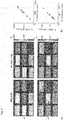
- FIGs. 3 , 4 , 6 and 7 include quantitative diagrams and/or photographs, which are helpful to illustrate and understand the present invention. These figures cannot be presented otherwise, e.g. as mere black and white line drawings.
- Fig. 1 shows a schematic representation of a pulse sequence 1 as used in the method according to a preferred embodiment of the present invention.
- a pulse sequence 1 such as exemplarily shown in Fig. 1 is driven by means of an NMR apparatus (not shown).
- the pulse sequence 1 comprises a preparation phase 2 and a plurality of acquisition phases 3.
- acquisition phases 3 a plurality (i.e. N sets) of imaging data are acquired using excitation by an excitation module 5, followed by an image readout module 6, depletion of the transversal magnetization by means of a spoiling module 7 and fat suppression by means of a fat suppression module 8.
- Acquisition phase 3 acquisition of N sets of imaging data: This phase consists of an excitation module, i.e. an excitation pulse 5, followed by image readout 6, depletion of the transversal magnetization 7 and fat suppression 8. This phase is applied N times after each other.
- an excitation module i.e. an excitation pulse 5, followed by image readout 6, depletion of the transversal magnetization 7 and fat suppression 8.
- This phase is applied N times after each other.
- the flip angle of the excitation pulse 5 and the timing of the blocks or modules within this phase 3 e.g. changing the time between the excitation pulse 5 and the image readout 6
- the contrast of the image data changes.
- the flip angles of the excitation pulse 5 and the timing of the blocks within the acquisition phase 3 have to change throughout the measurement, as by this contrast variation is induced.
- timing does not necessarily need to change with each new acquisition phase 3 over the course of the pulse sequence 1 with N blocks, at least two different timings need to be used.
- the acquisition phase 3 is preferably applied at least 10 times. There is no upper limit how often the phase is applied.
- Inversion pulse 4 Applying an inversion pulse 4 is an exemplary magnetization preparation for T1. The inversion pulse 4 flips the longitudinal magnetization by 180°.
- Excitation module 5 The excitation module 5 comprising an excitation pulse is used to flip some or all of the longitudinal magnetization into the transversal plane.
- Image readout module 6 Collection of image data is performed on a Cartesian grid using Echo Planar Imaging (EPI).
- EPI Echo Planar Imaging
- the advantage of using EPI based on a Cartesian is that robust trajectory and image distortion correction algorithms are widely available, enabling the measurement with Cartesian techniques on every clinical MRI machine.
- sequences based on Cartesian imaging have been shown to be more robust against hardware inaccuracies, providing more consistent image quality over a wide range of scan environments.
- Non-Cartesian imaging on the other hand, and spiral imaging in particular, is sensitive to the exact sequence trajectory. Deviations are induced by gradient inaccuracies and delays in the gradient switching time. Accurate trajectory calibration is necessary for spiral imaging, and is not available on commercial MRI scanners. Its availability is restricted to few research centers world-wide. Generally non-Cartesian imaging can be used in the pulse sequence.
- Spoiling module 7 (depletion of the transversal magnetization): Spoiling is used in the sequence to make it more robust. While spoiling reduces the overall signal strength throughout the pulse sequence 1, the sequence is more robust compared to non-spoiled sequences, as with non-spoiled sequences resulting phase errors can accumulate over time. Due to spoiling, the contrast from one acquisition phase 3 to the next is only transferred by the longitudinal magnetization. Spoiling needs to be performed after an image readout 6 and before an excitation 5. There are multiple methods to perform spoiling, e.g. gradient spoiling or RF-spoiling. For the pulse sequence design, it is not essential with which method the spoiling is performed.
- Fat saturation is used to suppress the off-resonance fat signals, as these cause artifacts in images. Fat suppression can be performed by many different well known methods such as using a chemically selective pulse to saturate the fat signal.
- a pulse sequence 1 is applied, in which the magnetization is initially prepared with a T1 sensitizing module (e.g. inversion or saturation pulse). Subsequently, N images are rapidly acquired with varying contrast. To allow joint quantification of the T1 and T2* time, the induced contrasts are generated by modifying contrast parameters of each image independently and by depletion of the transverse magnetization (spoiling) at the end of each of the N imaging cycles.
- T1 sensitizing module e.g. inversion or saturation pulse
- an MRF strategy as proposed by the present invention according to a preferred embodiment is based on the acquisition of a series of gradient echo-EPI images with varying flip angles (FAs) and echo times (TEs) to enable the joint quantification of T1 and T2*.
- FAs flip angles
- TEs echo times
- minimal TR may be chosen for any given TE.
- Fig. 2A shows a schematic diagram of the MRF-EPI with multiple EPI readouts, each with a different echo time TE and flip angle ⁇ .
- a single nonselective adiabatic hyperbolic secant inversion pulse is applied at the beginning of the sequence followed by multiple EPI readouts 6.
- a fat suppression 5 using spectrally-selective saturation is applied before each excitation 5.
- crusher gradients with equal polarity are performed before and after the saturation pulse 5.
- RF spoiling (not explicitly shown in Fig.
- Fig. 1A is included in the excitation pulse 5, e.g. with a phase increment of 50°. It is noted that in Fig. 2A gradient spoiling and fat saturation are illustrated as only one block or module, while in Fig. 1 the spoiling and fat saturation are shown as separate modules. In the example of Fig. 2 , the number N of imaging data sets or measurements is 160.
- Fig. 2B shows a schematic diagram of pulses applied by a radio frequency (RF) and analog-to-digital (ADC) system as well as a gradient system of an NMR apparatus in order to implement the pulse sequence 1 according to Fig. 2A , the gradient system comprising magnetic field gradients G x , Gy and G z .
- the gradient system comprising magnetic field gradients G x , Gy and G z .
- each EPI excitation module 5 and readout module 6 is preceded by a fat saturation module 8 including gradient spoiling.
- the technical implementation of the sequence shown in Fig. 2A by means of the field gradients G x , Gy and G z is standard in the art and thus not further described herein.
- the flip angles of the baseline images can be chosen in a pseudo-random manner.
- An example is shown in Fig. 2C , where an exemplary profile of the flip angle variation is illustrated.
- the flip angle varies throughout the measurements, i.e. throughout the acquisition phases.
- Fig. 2D shows an exemplary profile of echo time variations that can be used for MRF measurements.
- the echo time (TE) varies throughout the measurements, i.e. throughout the acquisition phases.
- a range of TEs from 14-75ms is preferably chosen, which results in additional T1 and T2* weighting in the proposed sequence design.
- the distribution of TEs, as shown in Fig. 2D may be empirically selected with a majority of short TEs to result in good SNR and short scan-times, a few long TEs to increase sensitivity to tissues with long T2* values, and an alternating pattern to create large contrast variations.
- the acquisition of several images with diverse contrasts is proposed in rapid succession enabled by depletion of the transversal magnetization and ultra-short imaging readout (e.g. EPI) to allow for the extraction of quantitative parameter maps.
- EPI ultra-short imaging readout
- the dictionary may be generated off-line by simulating the evolution of the magnetization m based on Bloch-equation simulations.
- the simulation software MATLAB The MathWorks; Natick, MA
- m l S E l R x k ⁇ l m l ⁇ 1 + Id ⁇ E l 0 0 1 T , where R x ( k ⁇ ) denotes a rotation about the x-axis by the angle ⁇ induced by the excitation pulse.
- R x ( k ⁇ ) denotes a rotation about the x-axis by the angle ⁇ induced by the excitation pulse.
- a B 1 + correction may be implemented. Performing such a correction of the RF-field B 1 can be advantageous for quantification accuracy, as B 1 is generally not homogeneous and thus the flip angle of the excitation pulse can differ from what is expected according to the nominal field strength.
- the dictionary may be extended to allow for a B 1 + amplitude correction using a linear scaling factor k in the range of 0.6-1.4 in steps of 0.1.
- the step size may be set to 0.1 to limit the size of the dictionary, as the dictionary size scales linearly with the number of steps.
- T 2 * dephasing is generally described by a non-exponential signal decay
- the use of a single exponential decay as approximate signal model is the most used method.
- single exponential mapping may be used for T 2 * quantification.
- the SNR may be set to 10, each fingerprint may be matched 10,000 times with different noise, and the remaining sequence parameters may be simulated as described above.
- f m is a continuous function in ⁇ .J fm ( ⁇ ) denotes the corresponding Jacobian Matrix for the parameters ⁇ .
- J fm ( ⁇ ) + denotes the pseudo-inverse of the Jacobian.
- the noise vector n is assumed to be normally distributed with zero mean and standard-deviation ⁇ , n ⁇ N (0 , ⁇ 2 ).
- ) can be neglected and is ignored for the rest of the analysis.
- ⁇ 2 m ⁇ 0 2
- Fig. 3A shows exemplary fingerprints of 40 dictionary elements with varying T 1 (500ms-3000ms) and T 2 * (10ms-100ms) values. Major contrast variations in the fingerprints are observed at various simulated T 1 and T2*.
- Fig. 3B shows the dependency of the precision from TE max .
- a TE pattern with small TE max provides sufficient precision
- TE max 75ms was chosen as a compromise between precision and measurement time which gives sufficient precision in the in-vivo range of T 2 * ( ⁇ 150ms).
- imaging was performed on a 3 T whole-body scanner (Magnetom Trio; Siemens Healthcare, Erlangen, Germany) using the whole body coil for transmission.
- a 32-channel head receiver array was used for in-vivo measurements and a flex coil in combination with the spine coil for phantom scans.
- This study was approved by the local institutional review board (IRB) and all subjects provided written informed consent, prior to examination.
- IR-TSE inversion-recovery turbo spin-echo
- GRE multi-gradient echo
- Reference values for T 1 and T 2 * were determined voxel-wise, fitting a three-parameter model for T 2 * a e ⁇ t / T 2 * + c and two-parameter model for T 1 ( a (1 - e -t / T 1 )) to the image magnitudes using a nonlinear least-squares fitting algorithm.
- Fig. 4A shows T1 and T 2 * maps obtained in phantom measurements using MRF-EPI according to a preferred embodiment of the method according to the present invention and the respective reference method IR-TSE and GRE.
- Visually comparable image quality is observed between MRF-EPI and the gold standard in the T1 maps.
- Slightly decreased homogeneity throughout the phantom compartments is obtained in the T 2 * maps, due to unavoidable field inhomogeneities.
- Fig. 4B shows a comparison of T1 and T 2 * values of MRF-EPI according to a preferred embodiment of the method according to the present invention with the reference methods. The comparison showing good agreement between the average relaxation times in all phantoms.
- the proposed method with B 1 + correction yields homogenous T 1 estimates within the phantoms.
- All T 2 * maps show a higher degree of variation than T 1 maps, due to unavoidable susceptibilities and large field inhomogeneities influencing the T 2 * values.
- B 1 + correction both T 1 and T 2 * times are substantially underestimated using MRF-EPI (T 1 deviation from IR-TSE in the range from -18% to -5%, T 2 * deviations from GRE in the range from -15% to 13%).
- Fig. 5A shows that complex matching results in a 2-fold (2.2 ⁇ 0.7) and 3-fold (3.0 ⁇ 1.0) higher quantification variance than magnitude matching in phantom scans, for T 1 and T 2 * respectively.
- Fig. 5B shows that the quantified relaxation times of the phantoms are nearly identical for magnitude and complex matching (deviation of complex from magnitude matching T 1 /T 2 *: 0 ⁇ 1% / -2 ⁇ 2%).
- MRF-EPI data was successfully acquired in all volunteers. The achieved image quality allowed for further post-processing of all data sets.
- Fig. 6 shows an exemplary fingerprint of a healthy subject.
- MRF baseline images show high image quality with no visible imaging artifacts. Strongly varying T 1 and T 2 * weighting can be observed over the course of the measurement. The signal intensity periodically increases and decreases due to the sinusoidal choice of the FAs.
- Fig. 7 shows representative T 1 and T 2 * maps of the MRF-EPI and the gold standard measurements from one healthy subject.
- the mean T 1 and T 2 * values obtained with MRF-EPI and gold standard sequences measured in manually drawn ROIs were: white matter 831 ⁇ 62ms/50 ⁇ 1 ms (MRF-EPI), 790 ⁇ 56ms/48 ⁇ 3ms (gold standard), gray matter: 1818 ⁇ 175ms/50 ⁇ 4ms (MRF-EPI), 1751 ⁇ 131ms/48 ⁇ 6ms (gold standard).
- T 1 maps are homogenous throughout gray and white matter, respectively.
- T 2 * maps show detailed structures and intracerebral susceptibilities. Strong T 2 * shortening is apparent close to tissue / air interface at the auditory canal or the sinus.
- an EPI based MRF method that allows for rapid quantification of T 1 and T 2 * times in 10 seconds per slice is provided.
- Good quantification accuracy can be achieved in phantom scans, comparable to previously proposed methods.
- In-vivo scans yield robust and artifact free parameter maps, with in-vivo relaxation parameter values that are in good agreement with the reference scans.
- the EPI-MRF single shot acquisition according to an embodiment of the present invention is considerably slower, as it does not allow for the same level of undersampling. Therefore, only a reduced number of frames can be acquired during a 10 second measurement, despite the use of parallel imaging to accelerate data acquisition. However, the fewer frames benefit from higher SNR.
- the proposed method is based on gradient and RF spoiled imaging, which is resilient to banding-artifacts and incomplete gradient refocusing, and potentially allows for arbitrary flip-angles.
- Sequences based on EPI readout suffer from their own set of challenges.
- the most common artifacts are geometric distortions due to mistiming or inaccuracy in the gradient amplitude induced by residual eddy currents. Field inhomogeneities can further lead to blurring, Nyquist ghosting and signal loss, the latter often seen in the temporal and frontal lobes. As these effects have long been target of research, robust algorithms are available for most of the named artifacts, such as acquiring flied maps to correct geometric distortions.
- EPI compatible MRI hard- and software is installed worldwide and supported by commercial vendors throughout the world, providing robust EPI sequences used in clinical routine.
- the proposed implementation might offer a complimentary approach to study and utilize the MRF paradigm.
- the proposed method was used to jointly assess T 1 and T 2 * tissue characteristics. Both have been shown to be of clinical interest as highly specific biomarkers for distinct pathologies.
- the original MRF method proposed the joint quantification of T 1 and T 2 maps. This can also be achieved in MRF-EPI by employing refocused EPI readouts to induce T 2 weighting. Increased SNR can be expected in refocused EPI readouts and the real part of the imaging data, can be readily used in post-processing due to the elimination of off-resonance dependencies. Hence, MRF-EPI also bares promise for robust T 1 and T 2 quantification.
- the proposed method employed a simplified B 1 + correction compared to previous studies, where the inventors proposed to alter the flip-angle scheme in order to increase B 1 + estimation accuracy.
- the original flip-angle scheme was employed, accepting a slight drop in accuracy.
- incorporating B 1 + estimation in the dictionary greatly improved parameter estimation, while the resulting B 1 + map possibly suffers from systematic errors.
- the magnitude data was used for pattern matching. Complex matching of the data can be employed to derive additional off resonance maps.
- the increased number of fit parameters results in lower quantification precision. Therefore, magnitude matching was chosen for MRF-EPI.
- a MRF sequence with spoiled EPI readout is proposed according to a preferred embodiment of the present invention.
- a pulse sequence for acquiring MRF data based on spoiled EPI readouts for joint T 1 and T 2 * quantification is proposed, as an alternative to balanced non-Cartesian imaging, potentially facilitating improved robustness and increased usability. Rapid T 1 and T 2 * quantification can be performed within 10 seconds per slice and yield in-vivo relaxation parameter maps of high quality.
- EPI for MRF fosters its usability and offers a complementary approach to existing MRF sequences.
- the proposed MRF method (MRF-EPI) according to a preferred embodiment is based on the acquisition of a plurality (e.g.
- MRF magnetic resonance fingerprinting
- EPI echo-planar imaging
- the proposed method enables fast and accurate T1 and T 2 * quantification.
- the proposed method offers a rapid supplement to the non-Cartesian MRF portfolio, with potentially increased usability and robustness.
Landscapes
- Physics & Mathematics (AREA)
- General Physics & Mathematics (AREA)
- Engineering & Computer Science (AREA)
- High Energy & Nuclear Physics (AREA)
- Condensed Matter Physics & Semiconductors (AREA)
- Nuclear Medicine, Radiotherapy & Molecular Imaging (AREA)
- Radiology & Medical Imaging (AREA)
- Signal Processing (AREA)
- General Health & Medical Sciences (AREA)
- Health & Medical Sciences (AREA)
- Artificial Intelligence (AREA)
- Computer Vision & Pattern Recognition (AREA)
- Magnetic Resonance Imaging Apparatus (AREA)
Abstract
The present invention relates to a method for analysing an object by means of nuclear magnetic resonance imaging. The method comprising
- issuing a pulse sequence (1) to an NMR apparatus, the pulse sequence (1) comprising a plurality of acquisition phases (3);
- within a respective acquisition phase (3), acquiring a corresponding set of imaging data; and
- quantifying at least one contrast parameter of the object based on the acquired sets of imaging data and simulated data;
wherein the acquisition phase (3) comprises the following steps in the given order:
-- an excitation step (5) for flipping a longitudinal magnetization of one or more nuclear spins in the object into a transversal plane by a variable flip-angle, thereby inducing a transversal magnetization;
-- an image readout step (6) for reading out the corresponding set of imaging data; and
-- a spoiling step (7) for depleting the transversal magnetization;
wherein a timing of the steps and/or the flip-angle is varied between at least two of the plurality of acquisition phases (3).
- issuing a pulse sequence (1) to an NMR apparatus, the pulse sequence (1) comprising a plurality of acquisition phases (3);
- within a respective acquisition phase (3), acquiring a corresponding set of imaging data; and
- quantifying at least one contrast parameter of the object based on the acquired sets of imaging data and simulated data;
wherein the acquisition phase (3) comprises the following steps in the given order:
-- an excitation step (5) for flipping a longitudinal magnetization of one or more nuclear spins in the object into a transversal plane by a variable flip-angle, thereby inducing a transversal magnetization;
-- an image readout step (6) for reading out the corresponding set of imaging data; and
-- a spoiling step (7) for depleting the transversal magnetization;
wherein a timing of the steps and/or the flip-angle is varied between at least two of the plurality of acquisition phases (3).
Further, the present invention relates to a corresponding computer program product, a control apparatus for NMR and to a nuclear magnetic resonance apparatus.
Description
- The present invention relates to a method for analysing an object by means of nuclear magnetic resonance (NMR) imaging. Further, the present invention relates to a corresponding computer program product, a control apparatus for NMR and to a nuclear magnetic resonance apparatus.
- The quantification of tissue properties including the relaxation parameters such as T1, T2, and T2* using magnetic resonance imaging (MRI) has long been a major research goal, to facilitate interpatient comparability and quantitative diagnosis. The detection and staging of several diseases have been improved by the possibility of quantifying relaxation parameters. Examples include T1 and T2* mapping to investigate the iron content in the brain of patients suffering from Huntington's, Parkinson's, and Alzheimer's disease. Furthermore, T2* is used for blood oxygenation imaging of the brain and kidneys, and T1 for multiple system atrophy and diffuse ischemic and non-ischemic cardiomyopathy. However, long acquisition times prevent the integration of relaxation-parameter mapping into clinical brain scan protocols.
- Recently, an emerging technique called magnetic resonance fingerprinting (MRF) and various extensions thereof have been introduced. In MRF, the acquisition of numerous baseline images with varying imaging parameters such as repetition time (TR) or flip angles (FA) yield spatially resolved characteristic signal evolutions which depend on the physical properties of the underlying tissue, such as relaxation times. Matching this "fingerprint" to a pre-computed dictionary that contains simulated signal profiles yields quantitative parameter maps.
- The original implementation of the MRF paradigm is based on a balanced steady-state free precession (bSSFP) sequence design. The contrast in a bSSFP sequence allows for joint quantification of T1, T2, and off-resonance. Non-Cartesian imaging is conventionally employed to facilitate rapid image readout as required in a MRF sequence.
- However, within the present invention, it turned out that the conventional sequence design has several drawbacks. For example, due to inherent properties of the non-Cartesian image readout, there exists a high sensitivity of MRF sequences to gradient deviations. Especially spiral trajectories, as used in most MRF sequences can suffer from detrimental effects on the image quality, caused by gradient inaccuracies. Implementing a Cartesian readout instead of a conventional non-Cartesian readout may potentially mitigate some of the sensitivities that are inherent to non-Cartesian acquisitions. However, merely replacing the non-Cartesian image readout by a Cartesian readout may suffer from long scan times, far beyond what is clinically acceptable.
- Furthermore, within the present invention, it turned out that the spin-echo character of a conventionally used sequence can induce sensitivity to the choice of flip angles. In addition, the quantification based on a balanced sequence design can be sensitive to field inhomogeneities. Although a nonbalanced steadystate free precession (SSFP) imaging readout may be used instead of the conventional balanced sequence design in order to mitigate banding artifacts, this may result in a decreased signal-to-noise ratio (SNR).
- Thus, it is an object of the present invention to overcome the above mentioned drawbacks and to provide an improved method for analysing or investigating an object or specimen by means of nuclear magnetic resonance imaging. In particular, it is an object of the present invention to provide an improved pulse-sequence for acquiring MRF data. The method and/or pulse sequence having an increased robustness and an increased usability. This object is solved by the subject-matter of the independent claims. Preferred embodiments are subject to the dependent claims.
- According to one aspect of the present invention, a method for analysing an object by means of nuclear magnetic resonance imaging is provided. The method comprises:
- driving, by means of an NMR apparatus, a pulse sequence comprising a plurality of acquisition phases;
- within a respective acquisition phase, acquiring a corresponding set of imaging data; and
- quantifying at least one contrast parameter of the object based on the acquired sets of imaging data and simulated data;
- -- an excitation step or module for flipping a longitudinal magnetization of one or more nuclear spins in the object into a transversal plane by a variable flip-angle, thereby inducing a transversal magnetization;
- -- an image readout step or module for reading out the corresponding set of imaging data; and
- -- a spoiling step or module for depleting the transversal magnetization;
- The object to be investigated preferably comprises one or more "resonant species", wherein a resonate species refers to an item (e.g. water, fat, tissue) that can be made to resonate using NMR. The object may for example be at least a part of a human or an animal.
- A "pulse sequence" in the sense of the present invention is a sequence of pulses, such as excitation or radiofrequency (RF) pulses and/or magnetic field gradients, which are applied to the object to be investigated in order to generate a net magnetization that can be processed to an image by recording a current that is induced in a receiver coil of the NMR apparatus. The detected current may be converted using analog-to-digital (ADC) converters, wherein the corresponding events are referred to as ADC events. The totality of all RF pulses and magnetic field gradients and ADC events form the so called "pulse sequence".
- A "module" in the sense of the present description is to be understood such that a certain step or procedure is carried out. Accordingly, the term "module" may be replaced by the term "step" or "procedure".
- In general, RF pulses and magnetic field gradients can be combined in various ways to induce contrast weighting. Common building blocks can be used in pulse-sequences of different types, e.g. to convert contrast encoded in a longitudinal magnetization Mz to a signal in a transverse magnetization Mt that can be used for imaging.
- According to the present invention, the pulse sequence comprises a plurality of acquisition phases. In particular, the pulse sequence may comprise N sets of acquisition phases, wherein N is an integer > 0 and wherein N is preferably larger than ten.
- Within a respective acquisition phase, and particularly within each acquisition phase, a corresponding set of images and/or imaging data is acquired. In a next step, at least one contrast parameter, in particular the longitudinal relaxation time T1 and the transversal relaxation time T2*, of the object is quantified or determined based on the acquired sets of imaging data and simulated data. In particular, the acquired imaging data is reconstructed to quantitative maps for contrast parameters, e.g. T1 and T2*. In other words, the step of quantifying at least one contrast parameter of the object based on the acquired sets of imaging data and simulated data may encompass the step of reconstructing quantitative maps for contrast parameters, e.g. T1 and T2*, based on the acquired sets of imaging data and simulated data.
- For the quantification of contrast parameters or for the reconstruction of quantitative maps for contrast parameters, different methods may be used, such as dictionary matching or simulated annealing. In particular, the contrast parameters may be quantified by comparing the acquired imaging data with the simulated data.
- The simulated data may be pre-processed or pre-computed data. In particular, the simulated data represent an evolution of the magnetization. In particular, the simulated data represent signal evolutions for a plurality of different tissues or resonant species. The simulated data are preferably simulated or calculated based on mathematical and/or physical models using the Bloch-equations. The simulated data may be a dictionary as used by the MRF-technique.
- An acquisition phase, i.e. at least one acquisition phase and particularly each acquisition phase, comprises at least an excitation step, an image readout step and a spoiling step.
- Within the excitation step or excitation procedure, a RF-pulse is applied in order to flip a longitudinal magnetization of one or more nuclear spins in the object into a transversal plane by a variable, particularly pseudo-random, flip-angle, thereby inducing a transversal magnetization, i.e. a magnetization component in the transversal plane. The longitudinal magnetization is a magnetization in the direction (z-direction) of an applied uniform magnetic field, the polarizing magnetic field Bo. The transversal magnetization is a magnetization in the transversal plane (x-y-plane). When a substance such as a human tissue is subjected to the polarizing field Bo, the individual magnetic moments of the nuclear spins in the tissue attempt to align with this polarizing field, but precess about it in random order at their characteristic Larmor frequency. This results in a net magnetic moment Mz in the direction of the polarizing field, while the randomly oriented magnetic components in the perpendicular or transverse plane (x-y plane) cancel each other. If the substance is subjected to an excitation field B1 (RF-field) being applied in the x-y plane and having the Larmor frequency or a frequency near the Larmor frequency, the longitudinal magnetization Mz may be rotated or flipped into the x-y plane, thereby resulting in a net transverse magnetic moment Mt. This net transverse magnetic moment Mt rotates or spins in the x-y plane at the Larmor frequency.
- A "variable" flip-angle means within the present invention that the flip-angle can change from one acquisition phase to another. However, during one acquisition phase, the flip-angle is constant, i.e., during each one of the acquisition phases a distinct or predetermined flip-angle is used. Accordingly, the expression "variable" in the sense of the present invention means that the predetermined flip-angle of one acquisition phase may differ from the predetermined flip-angle of another acquisition phase. In particular, the variable flip angle may be a pseudo-random flip-angle. In other words, the flip-angle may change in a pseudo-random manner from one acquisition phase to the following or next acquisition phase. In other words, the flip-angle may change in a pseudo-random manner between two consecutive acquisition phases.
- Within the image readout step or image readout procedure gradient pulses may be applied for reading out the corresponding set of imaging data.
- By means of the spoiling step or spoiling procedure the transversal magnetization is depleted. Spoiling is used in the sequence to make it more robust. While spoiling reduces the overall signal strength throughout the pulse sequence, the sequence is more robust compared to non-spoiled sequences, as with non-spoiled sequences resulting phase errors can accumulate over time. Due to spoiling, the contrast from one acquisition phase to the next is only transferred by the longitudinal magnetization. Spoiling is performed after image readout but before the excitation. There are multiple methods to perform spoiling, e.g. gradient spoiling or RF-spoiling. In particular, spoiling may be performed by applying gradients with variable amplitudes at the end of each cycle. The strength of the spoiler gradient may be varied linearly or, more preferably, semi-randomly from view to view. RF spoiling involves applying a phase offset to each successive excitation pulse. It is noted that for the pulse sequence design according to the present invention it is not important with which method the spoiling is performed.
- In view of the conventional MRF, it is noted that spoiling cannot be included into the pulse sequence without major changes, since the conventional pulse sequence is based on a balanced sequence design. A balanced sequence generally starts out with an RF excitation pulse of 90° or less and the spins in the steady state, by this meaning they are in a stable state. Prior to the next measurement, the gradients are balanced so their net value is zero. In a non-balanced sequence, however, as it is the case according to the present invention, the net value is non-zero at the end of each acquisition step.
- Between at least two of the plurality of acquisition phases a timing of the steps (modules) and/or the flip-angle is varied. This changes the contrast of the acquired imaging data. The term "timing" particularly encompasses or refers to various characteristic times being crucial for NMR and/or MRI (herein referred to as NMR-times or MRI-times), such as an echo time, a repetition time, a waiting or delay time, and/or a time between the excitation step and the image readout step.
- In other words, the method according to the present invention comprises acquiring of N sets of imaging data, using excitation by a flip angle, followed by an image readout and a depletion of the transversal magnetization. Each of the N images can differ in contrast as induced by, e.g., varying the flip angle and/or waiting times. Quantitative maps for contrast parameters, particularly for T1 and T2*, can then be reconstructed based on the imaging data.
- According to the present invention, N images are rapidly acquired with varying contrast. To allow joint quantification of the T1 and T2* relaxation time the induced contrasts are generated by modifying contrast parameters of the acquired images independently and by depletion of the transverse magnetization (spoiling) at the end of each of the N imaging cycles.
- Thus, by the method according to the present invention, and particularly by the pulse sequence design according to the present invention, it is possible to simultaneously quantify the relaxation parameters T1 and T2*, opposed to T1 and T2 as with the conventional MRF-technique.
- Furthermore, the method according to the present invention has an increased robustness and an increased usability compared to conventional methods. This is because balanced sequence designs, as conventionally used, need to keep the magnetization in a controlled state to exert the so called "spin-echo character", i.e. the sensitization to a T2 decay. However, within the present invention it turned out that parameter variation can compromise this "spin-echo character" and accordingly the quantification accuracy. Moreover, the first moment of the magnetic field gradients needs to be balanced, which requires exact calibration of the gradient field strength. In commercially available MRI scanners, this cannot be achieved and cancelation of the gradient moments remains incomplete due to imperfections or non-linearities in the gradient fields. Thus, resulting phase errors can accumulate over time. A Spoiled sequence design on the other hand, as used according to the present invention, is robust towards the parameter choice, as the contrast is encoded in the longitudinal rather than the transverse magnetization. Furthermore, gradient moments are not to be balanced and, hence, inaccuracies are not affecting the sequence's fidelity. Lastly, thorough depletion of the transverse magnetization prevents any accumulate of such inaccuracies.
- The method can be directly and with no further modification applied to all areas of imaging including neuroimaging, prostate imaging (e.g. prostate cancer), cartilage imaging or imaging of extremities. With minor modifications, e.g. the insertion of trigger and or gating events, relative to physiological signals, the sequence might be used for abdominal or cardiac applications.
- In a preferred embodiment, the image readout step, and particularly an Echo Planar Imaging (EPI), is based on a Cartesian readout. In other words, the collection of imaging data is preferably performed on a Cartesian grid, for example by using Echo Planar Imaging.
- In MRI image data is collected as samples in the space of spatial frequencies, the so called "k-Space". Magnetic gradient fields are employed to modulate the phase of the magnetization as a function of the spatial location, therefore, varying the sample location in the k-Space. A sufficient sampling of the k-Space allows for image generation by converting the spatial frequencies to image information by means of a Fourier-Transform. If the necessary image information in the k-space is sampled on a grid with orthogonal gridlines (i.e. "Cartesian"), the image acquisition is referred to as "Cartesian" imaging. Contrary to a Cartesian imaging, other trajectories are conventionally used to traverse through k-space and collect image data. If the resulting sampling locations on those trajectories do not resemble a "Cartesian" grid, the imaging is called "non-Cartesian". Acquiring data at sample locations on a spiral trajectory is for example referred to as "spiral imaging".
- Non-Cartesian imaging, and spiral imaging in particular, as it is conventionally used for the MRF technique is sensitive to the exact sequence trajectory. Deviations are induced by gradient inaccuracies and delays in the gradient switching time. Accurate trajectory calibration is necessary for spiral imaging, and is not available on commercial MRI scanners. Its availability is restricted to few research centers world-wide. For a rapid Cartesian imaging on the other hand robust trajectory and image distortion correction algorithms have been proposed and are widely available, enabling the measurement with Cartesian techniques on every clinical MRI machine. Furthermore, sequences based on Cartesian imaging are more robust against hardware inaccuracies, providing more consistent image quality over a wide range of scan environments.
- In particular, it has been found out within the present invention that by using spoiling in combination with a Cartesian readout, the pulse sequence is more robust in comparison to the previously proposed sequence design. Both non-Cartesian readout and balanced elements of the pulse sequence make the original MRF technique susceptible to artifacts due to system imperfections in conventional MRIs. Only by replacing both components by a Cartesian readout and spoiling (so no balanced design), the pulse sequence becomes more robust to system imperfections.
- In a further preferred embodiment, the image readout step comprises or is an Echo Planar Imaging (EPI).
- After a net magnetization is formed and excited, an ADC event will eventually be launched. Magnetic gradient fields that are turned on during the ADC event, allow traversing through the k-space during the data collection, thereby enabling the sampling of multiple locations for a single excitation. In Echo Planar Imaging the duration of the ADC-event is prolonged and magnetic gradient fields are active during the ADC event, in such a way that multiple lines on a Cartesian grid are sampled following a single excitation. This advantageously allows the image generation based on a single RF excitation of the net magnetization.
- In a further preferred embodiment, spectral and or spatial selective pulses for chemical and/or regional saturation of tissue may be applied for an improved contrast. In particular, one or more acquisition phases, preferably each acquisition phase, further comprises a fat saturation step or a fat saturation procedure.
- Fat saturation is advantageously used to suppress the off-resonance fat signals, as these cause artifacts in images. There are many different methods how to do a fat saturation, e.g. using a chemically selective pulse to saturate the fat signal. The fat saturation is preferably used before each excitation.
- In a further preferred embodiment, the pulse sequence further comprises one or more preparation phases before or during the plurality of acquisition phases. The one or more preparation phases may comprise an initial magnetization preparation using, e.g., a T1 sensitizing step or module.
- Preparations can be used at the beginning or during the pulse sequence. The aim of the preparation is to increase sensitivity of the measurement to a special contrast parameter. For example, it is possible to increase sensitivity of the relaxation parameter T1 by including an inversion pulse in order to flip the longitudinal magnetization by 180°. The preparation is optional, as the quantification of T1 and T2* also works without the preparation, though this module increases the precision of the quantification. The preparation can also include depletion of the transversal magnetization and fat suppression.
- In a further preferred embodiment, the one or more preparation phases comprise one or more inversion pulses, particularly an initial magnetization preparation procedure using, e.g., a T1 sensitizing module. Additionally or alternatively, the one or more preparation phases comprise one or more depletion pulses for depleting the transversal magnetization. Additionally or alternatively, the one or more preparation phases comprise one or more fat suppression pulses. Thereby, the quality, robustness and/or sensitivity of the method can be further increased.
- In a further preferred embodiment, the step of quantifying at least one contrast parameter of the object comprises jointly or simultaneously quantifying the longitudinal relaxation time T1 and the transversal relaxation time T2*. T1 and T2* refer to the well known relaxation times in NMR. T1 is also known as the spin-lattice relaxation time, while T2 is also known as the spin-spin relaxation time. T2* differs from T2 in that T2* is, contrary to T2, further influenced by a magnetic field inhomogeneity and/or magnetic field gradient irregularities. The T2* relaxation time is always shorter than the T2 relaxation time and is typically milliseconds for water samples in imaging magnets. It is noted that by means of a pulse sequence used in the conventional MRF-technique, only T1 and T2 can be quantified simultaneously. By means of the pulse sequence used in the method according to the present invention, however, the joint or simultaneous quantification of T1 and T2* is possible.
- In a further preferred embodiment, the step of quantifying at least one contrast parameter of the object comprises a dictionary matching or a simulated annealing.
- The signal during any of such pulse-sequences can be modeled using experimentally verified physical models, such as the "Bloch equations". Dictionary Matching refers to reconstruction of quantitative parameter maps, i.e. finding the contrast parameters that best describe the observed signal, by evaluating the pulse-sequence model at a defined set of parameters. The matching parameters are then chosen as the ones which produce the least deviation from the measured signal. This resembles a grid search minimizing the difference between the pulse-sequence model and the acquired signal. Alternative minimization algorithms are well known and can be applied to this optimization task. The main advantages of dictionary matching are the ease of implementation, as well as the robustness against local minima. The usage of pre-computed dictionaries also offers computational advantages if the objective function is computationally expensive, i.e. the pulse-sequence model is computationally expensive to evaluate.
- Simulated Annealing is an alternative optimization technique, where the search space (i.e. the parameter space) is evaluated at pseudo-random locations. The optimization algorithm starts from a defined point in the search space. The next search location is then defined to lie in a neighborhood around the current putative minimum. The size of this neighborhood is reduced over time, as the putative minimum gets refined. This optimization has been shown to be robust to local minima, while providing an ordered search and avoiding unnecessary function evaluations is areas that are not of interest.
- In a further preferred embodiment, the spoiling step or module is performed directly, i.e. without any further steps or modules in between, after performing the image readout step. Furthermore, the spoiling step is preferably performed before performing a possible next excitation step or an excitation step which belongs to a possible next acquisition phase.
- In a further preferred embodiment, the spoiling step comprises gradient spoiling or radio frequency spoiling. Gradient spoiling is performed by applying gradients with variable amplitudes at the end of each cycle just before the next RF (radio frequency) pulse. The strength of the spoiler gradient is varied linearly or semi-randomly from view to view. Radio frequency (RF) spoiling involves applying a phase offset to each successive excitation pulse.
- In a further preferred embodiment, the applied pulse sequence is based on a non-balanced sequence design. As already discussed above, a pulse sequence which is based on a non-balanced sequence design becomes more robust to system imperfections.
- According to a further aspect of the present invention, a computer program product is provided, the computer program product comprising a computer readable storage medium, particularly a non-transitory readable storage medium, having encoded thereon instructions that, when executed on a processor, cause the processor to perform a method according to the present invention.
- According to a further aspect of the present invention, there is provided a control apparatus for NMR comprising a processor or a computer being configured to perform the method according to the present invention.
- According to a further aspect of the present invention, there is provided a nuclear magnetic resonance apparatus comprising:
- a magnet system for generating a main magnetic field;
- a gradient system for generating gradient fields;
- a radio frequency system for generating radio frequency pulses; and
- a control apparatus comprising a processor or a computer being configured to perform the method according to the present invention.
- The main magnetic field may be a uniform and/or polarizing magnetic field B0, which is particularly directed into the z-direction. The gradient system and/or the radio frequency system may generate an excitation field B1 (RF-field), particularly in the x-y-plane.
- For the above mentioned further independent aspect and in particular for preferred embodiments in this regard, the explanations given above or below concerning the embodiments of the first aspect also hold true. In particular, for one independent aspect of the present invention and for preferred embodiments in this regard, the explanations given above and below concerning the embodiments of the respective other aspects also hold true.
- Individual embodiments for solving the problem are described by way of example below with reference to the figures. In this case, the individual embodiments described have in part features which are not absolutely necessary for implementing the claimed subject matter, but which provide desired properties in specific applications. In this regard embodiments which do not have all the features of the embodiments described below are also intended to be regarded as disclosed in a manner coming under the technical teaching described. Furthermore, in order to avoid unnecessary repetitions, specific features are mentioned only with regard to individual embodiments from among the embodiments described below. It is pointed out that the individual embodiments are therefore intended to be considered not only by themselves but also in a joint consideration. On the basis of this joint consideration the person skilled in the art will recognize that individual embodiments can also be modified by inclusion of individual or a plurality of features of other embodiments. It is pointed out that a systematic combination of the individual embodiments with individual or a plurality of features described with regard to other embodiments may be desirable and expedient and is therefore intended to be taken into account and also to be regarded as encompassed by the description.
- The above and other objects, features and advantages of the present invention will become more apparent upon reading of the following description of preferred embodiments and accompanying drawings. Other features and advantages of the subject-matter described herein will be apparent from the description and the drawings and from the claims. It should be understood that even though embodiments are separately described, single features and functionalities thereof may be combined without prejudice to additional embodiments. The present disclosure is illustrated by way of example and not limited by the accompanying figures.
- Preferred embodiments of the present invention are exemplarily described regarding the following figures:
- Fig. 1
- shows a schematic representation of a pulse sequence as used in the method according to a preferred embodiment of the present invention;
- Fig. 2
-
- A) shows a schematic diagram of a pulse sequence according to a preferred embodiment, similar to
Fig. 1 ; - B) shows a schematic diagram of corresponding pulses applied by a radio frequency system and a gradient system of an NMR apparatus;
- C) shows exemplary profiles of the flip angle variations;
- D) shows exemplary profiles of the echo time variations;
- A) shows a schematic diagram of a pulse sequence according to a preferred embodiment, similar to
- Fig. 3
-
- A) shows exemplary fingerprints from a simulated dictionary for a range of T1 and T2* values;
- B) shows the quantification precision in dependence of the maximum TE time of the TE pattern for a variety of T2* values (T1 = 1000ms), wherein for the emphasized curve T2* = 150 ms; For short T2* values a TE pattern with small TEmax provides sufficient precision, this does not hold for long T2* values;
- Fig. 4
-
- A) shows T1 and T2* maps obtained in phantom measurements using MRF-EPI according to a preferred embodiment of the method according to the present invention and the respective reference method IR-TSE and GRE;
- B) shows a comparison of T1 and T2* values of MRF-EPI according to a preferred embodiment of the method according to the present invention with the reference methods, showing good agreement between the average relaxation times in all phantoms;
- Fig. 5
-
- A) shows the quantification variance of the phantoms for complex and magnitude matching. Complex dictionary matching leads to a higher quantification variance than magnitude matching;
- B) shows measurement results illustrating that the quantified relaxation times T1 and T2* of the phantoms are nearly identical for complex and magnitude matching;
- Fig. 6
- shows a fingerprint from one voxel of a healthy object or subject (male, 30 years old) and exemplary images with corresponding TE, TI (scan time since inversion pulse), flip angle α and SNR, reconstructed from individual EPI readouts according to a preferred embodiment of the method according to the present invention. The images showing highly varying contrast over the course of the measurement. Strongly T1 weighted contrast is observed in the beginning of the measurement (#4, #10), while increasing T2* weighting is observed at the end of the sequence (#121, #160);
- Fig. 7
- shows T1, T2* and B1+ maps generated with MRF-EPI according to a preferred embodiment of the method according to the present invention and the reference methods IR-TSE (T1) and GRE (T2*) in a healthy volunteer (female, 25 years old). Good homogeneity is observed within the gray and white matter of the MRF-EPI T1 map. The T2* maps clearly reflect intra-cerebral susceptibilities, and shortened T2* times are observed in the vicinity to tissue air transitions, e.g. at the auditory canal or the sinus.
- It is noted that
Figs. 3 ,4 ,6 and7 include quantitative diagrams and/or photographs, which are helpful to illustrate and understand the present invention. These figures cannot be presented otherwise, e.g. as mere black and white line drawings. - The following detailed description relates to exemplary embodiments of the present invention. Other embodiments of the invention are possible within the scope of the invention as defined by the appended claims. Throughout the figures, same reference signs are used for the same or similar elements.
-
Fig. 1 shows a schematic representation of apulse sequence 1 as used in the method according to a preferred embodiment of the present invention. According to the method of the present invention, apulse sequence 1 such as exemplarily shown inFig. 1 is driven by means of an NMR apparatus (not shown). - The
pulse sequence 1 comprises apreparation phase 2 and a plurality of acquisition phases 3. Within the acquisition phases 3, a plurality (i.e. N sets) of imaging data are acquired using excitation by anexcitation module 5, followed by animage readout module 6, depletion of the transversal magnetization by means of a spoiling module 7 and fat suppression by means of afat suppression module 8. - In the following, the different phases and modules of the
pulse sequence 1 are described: - Preparation phase 2: Preparations can be used at the beginning or during the
pulse sequence 1. The aim of the preparation is to increase sensitivity of the measurement to a special parameter, e.g. it is possible to increase sensitivity of the relaxation parameter T1 by including aninversion pulse 4 which flips the longitudinal magnetization by 180°. The preparation is optional, as the quantification of T1 and T2* also works without the preparation, though this module increases the precision of the quantification. The preparation can also include depletion of the transversal magnetization by means of a spoiling procedure 7 and fat suppression by means of afat suppression procedure 8. - Acquisition phase 3 (acquisition of N sets of imaging data): This phase consists of an excitation module, i.e. an
excitation pulse 5, followed byimage readout 6, depletion of the transversal magnetization 7 andfat suppression 8. This phase is applied N times after each other. By varying the flip angle of theexcitation pulse 5 and the timing of the blocks or modules within this phase 3 (e.g. changing the time between theexcitation pulse 5 and the image readout 6), the contrast of the image data changes. The flip angles of theexcitation pulse 5 and the timing of the blocks within theacquisition phase 3 have to change throughout the measurement, as by this contrast variation is induced. - While timing does not necessarily need to change with each
new acquisition phase 3 over the course of thepulse sequence 1 with N blocks, at least two different timings need to be used. Theacquisition phase 3 is preferably applied at least 10 times. There is no upper limit how often the phase is applied. - Inversion pulse 4: Applying an
inversion pulse 4 is an exemplary magnetization preparation for T1. Theinversion pulse 4 flips the longitudinal magnetization by 180°. - Excitation module 5: The
excitation module 5 comprising an excitation pulse is used to flip some or all of the longitudinal magnetization into the transversal plane. During the pulse sequence 1N excitation pulses 5 are played with various flip angles. While the flip angles do not necessarily need to change with eachnew acquisition phase 3, over the course of thepulse sequence 1 with N excitation, at least two different flip angles need to be used. Generally lower flip angles (< 60 degree) should be used, as the repetitive use of high flip angles will cause the magnetization to decline. Nevertheless, the use of a few high flip angles (>=60 degree) can make the sequence more robust, as by this, e.g., the inhomogeneous magnetic transmit field can be measured. - Image readout module 6: Collection of image data is performed on a Cartesian grid using Echo Planar Imaging (EPI). The advantage of using EPI based on a Cartesian is that robust trajectory and image distortion correction algorithms are widely available, enabling the measurement with Cartesian techniques on every clinical MRI machine. Hence, sequences based on Cartesian imaging have been shown to be more robust against hardware inaccuracies, providing more consistent image quality over a wide range of scan environments. Non-Cartesian imaging on the other hand, and spiral imaging in particular, is sensitive to the exact sequence trajectory. Deviations are induced by gradient inaccuracies and delays in the gradient switching time. Accurate trajectory calibration is necessary for spiral imaging, and is not available on commercial MRI scanners. Its availability is restricted to few research centers world-wide. Generally non-Cartesian imaging can be used in the pulse sequence.
- Spoiling module 7 (depletion of the transversal magnetization): Spoiling is used in the sequence to make it more robust. While spoiling reduces the overall signal strength throughout the
pulse sequence 1, the sequence is more robust compared to non-spoiled sequences, as with non-spoiled sequences resulting phase errors can accumulate over time. Due to spoiling, the contrast from oneacquisition phase 3 to the next is only transferred by the longitudinal magnetization. Spoiling needs to be performed after animage readout 6 and before anexcitation 5. There are multiple methods to perform spoiling, e.g. gradient spoiling or RF-spoiling. For the pulse sequence design, it is not essential with which method the spoiling is performed. - Fat saturation module 8: Fat saturation is used to suppress the off-resonance fat signals, as these cause artifacts in images. Fat suppression can be performed by many different well known methods such as using a chemically selective pulse to saturate the fat signal.
- Thus, in the method according to a preferred embodiment of the present invention, a
pulse sequence 1 is applied, in which the magnetization is initially prepared with a T1 sensitizing module (e.g. inversion or saturation pulse). Subsequently, N images are rapidly acquired with varying contrast. To allow joint quantification of the T1 and T2* time, the induced contrasts are generated by modifying contrast parameters of each image independently and by depletion of the transverse magnetization (spoiling) at the end of each of the N imaging cycles. - In particular, an MRF strategy (MRF-EPI) as proposed by the present invention according to a preferred embodiment is based on the acquisition of a series of gradient echo-EPI images with varying flip angles (FAs) and echo times (TEs) to enable the joint quantification of T1 and T2*. To optimize scan-time, minimal TR may be chosen for any given TE.
-
Fig. 2A shows a schematic diagram of the MRF-EPI with multiple EPI readouts, each with a different echo time TE and flip angle α. As shown in the sequence diagram ofFig. 2A , a single nonselective adiabatic hyperbolic secant inversion pulse is applied at the beginning of the sequence followed bymultiple EPI readouts 6. To suppress chemical-shift artifacts commonly observed with EPI sequences, afat suppression 5 using spectrally-selective saturation is applied before eachexcitation 5. To eliminate residual transverse magnetization from the non-selective excitation, crusher gradients with equal polarity are performed before and after thesaturation pulse 5. Additionally, RF spoiling (not explicitly shown inFig. 1A ) is included in theexcitation pulse 5, e.g. with a phase increment of 50°. It is noted that inFig. 2A gradient spoiling and fat saturation are illustrated as only one block or module, while inFig. 1 the spoiling and fat saturation are shown as separate modules. In the example ofFig. 2 , the number N of imaging data sets or measurements is 160. -
Fig. 2B shows a schematic diagram of pulses applied by a radio frequency (RF) and analog-to-digital (ADC) system as well as a gradient system of an NMR apparatus in order to implement thepulse sequence 1 according toFig. 2A , the gradient system comprising magnetic field gradients Gx, Gy and Gz. As shown inFig. 2B , eachEPI excitation module 5 andreadout module 6 is preceded by afat saturation module 8 including gradient spoiling. The technical implementation of the sequence shown inFig. 2A by means of the field gradients Gx, Gy and Gz is standard in the art and thus not further described herein. - The flip angles of the baseline images can be chosen in a pseudo-random manner. An example is shown in
Fig. 2C , where an exemplary profile of the flip angle variation is illustrated. The flip angle varies throughout the measurements, i.e. throughout the acquisition phases. -
Fig. 2D shows an exemplary profile of echo time variations that can be used for MRF measurements. The echo time (TE) varies throughout the measurements, i.e. throughout the acquisition phases. A range of TEs from 14-75ms is preferably chosen, which results in additional T1 and T2* weighting in the proposed sequence design. The distribution of TEs, as shown inFig. 2D , may be empirically selected with a majority of short TEs to result in good SNR and short scan-times, a few long TEs to increase sensitivity to tissues with long T2* values, and an alternating pattern to create large contrast variations. - Thus, according to the present invention, the acquisition of several images with diverse contrasts is proposed in rapid succession enabled by depletion of the transversal magnetization and ultra-short imaging readout (e.g. EPI) to allow for the extraction of quantitative parameter maps.
- In the following, it is described in detail how the simulated data can be obtained and matched to the acquired image data. Although other methods such as simulated annealing may be used, the following description exemplarily refers to MRF using a dictionary matching. Accordingly, a possible generation of the dictionary as well as details relating to the pattern validation, the pattern matching and the sequence parameters as used exemplarily by the inventors within the present invention are described in the following. Furthermore, phantom experiments and in-vivo experiments that have been performed by the inventors are presented and discussed in order to illustrate the potential and usability of the method according to the present invention.
- The dictionary may be generated off-line by simulating the evolution of the magnetization m based on Bloch-equation simulations. For this purpose, for example the simulation software MATLAB (The MathWorks; Natick, MA) can be used. The magnetization vector




- While T2* dephasing is generally described by a non-exponential signal decay, the use of a single exponential decay as approximate signal model is the most used method. To allow for comparability to this method, single exponential mapping may be used for T2* quantification. According to an example carried out by the inventors, the MRF dictionary consisted of 157,938 entries with the following parameter range: T1=20-2,000ms in steps of 10ms, and 2,000-6,000ms in steps of 500ms; T2*=10-100ms in steps of 2ms, and 100-300ms in steps of 5ms. Unrealistic entries with T1<T2* may be discarded.
- The maximum TE of the TE pattern may be chosen by calculating the quantification precision of T2* in dependence of various TE patterns. Fingerprints in the range of T1=1000ms and T2*=50-250ms may be simulated by linearly scaling the TE pattern so that TEmax is in the range of 14-100ms and matched to the dictionary in the presence of noise. The SNR may be set to 10, each fingerprint may be matched 10,000 times with different noise, and the remaining sequence parameters may be simulated as described above.
- To ensure separability of the dictionary elements in the presence of noise, the stability of the parameter quantification from MRF data was studied, thereby testing the influences of noise on the fingerprints. For this the inverse problem describing the parameter extraction from MRF data f was locally linearized. Two exemplary relaxation constants set in the in-vivo range and the noise amplification, induced by the inverse problem as a function of the overall number of images in the fingerprint, was analyzed. The MRF system was linearized for variable fingerprint length m

- Here


- Where Jfm (θ)+ denotes the pseudo-inverse of the Jacobian. The noise vector n is assumed to be normally distributed with zero mean and standard-deviation σ, n∼N(0,σ 2). For sufficiently large SNR, o(|e|) can be neglected and is ignored for the rest of the analysis. To represent equal scan time, the noise variance σ 2 is normalized by the number of images (σ2 = m σ 0 2), i.e. a lower number of images can be acquired with increased SNR. In the linear approximation, it follows that the components of e are normally distributed, as a sum of normal distributions in the noise input. Specifically, e T
1 ∼N(0, σ T1 2 ) and


amplification 
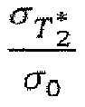
- All dictionaries were computed in approximately 10 minutes using a standard desktop computer.
-
Fig. 3A shows exemplary fingerprints of 40 dictionary elements with varying T1 (500ms-3000ms) and T2* (10ms-100ms) values. Major contrast variations in the fingerprints are observed at various simulated T1 and T2*. -
Fig. 3B shows the dependency of the precision from TEmax. For short T2* values a TE pattern with small TEmax provides sufficient precision, for long T2* values > 200ms, the gradient of the precision curve does not saturate at TEmax=100ms. TEmax=75ms was chosen as a compromise between precision and measurement time which gives sufficient precision in the in-vivo range of T2* (<150ms). - Dictionary matching may be performed by calculating the inner product between the magnitude of the dictionary entries and the magnitude of the measured signal. Dictionary matching based on correlation corresponds to a grid search minimization of the least squares error. This represents a maximum likelihood estimator for Gaussian noise. Hence, the Rician noise distribution, commonly observed in MRI magnitude data, potentially induces inaccuracy in the parameter estimation. To study the effect of Rician noise on the accuracy of the magnitude based dictionary matching, numerical simulations have been performed. Rician in noise was added to a simulated signal with relaxation times the in-vivo range (T1/T2*=1000-2000ms/30-130ms) to generate SNR values between 2 and 10. For each SNR value, 5000 signals with added noise were matched to the dictionary and the average difference between the matched and original relaxation parameters was calculated.
- According to an example, imaging was performed on a 3 T whole-body scanner (Magnetom Trio; Siemens Healthcare, Erlangen, Germany) using the whole body coil for transmission. A 32-channel head receiver array was used for in-vivo measurements and a flex coil in combination with the spine coil for phantom scans. This study was approved by the local institutional review board (IRB) and all subjects provided written informed consent, prior to examination. The following image parameters were used for all MRF-EPI phantom and in-vivo measurements: bipolar k-Space trajectory, TE/TR = 14-75ms/48-109ms, flip angle = 0 - 58°, matrix/FOV = 128x128/220x220mm2, BW = 1395Hz/pixel, slice thickness = 5mm, total gradient moment per spoiler = 69,6mT/m*ms, partial-Fourier = 6/8, parallel imaging factor = 3 with GRAPPA reconstruction, reference lines = 60 acquired in-place for each baseline image, gradient delay correction based on three navigator echoes, acquired prior to each readout, static geometric distortion correction, adaptive reconstruction of phased array, frames = 160, acquisition time per slice = 10s.
- Reference values for T1 were obtained using an inversion-recovery turbo spin-echo (IR-TSE) sequence with the following sequence parameters: 5 images, TI = 50-1600ms, TE/TR = 6ms/15s, turbo factor = 16, matrix/FOV=128x128/220x220mm2, BW = 399Hz/pixel, scan time = 10min 0sec. To estimate T2* times in phantoms, a spoiled gradient echo sequence (GRE) was employed and six images were acquired using the following parameters: TE = 5-80ms, TR = 1000ms, alpha = 15°, matrix/FOV = 128x128/220x220mm2, BW = 391 Hz/pixel, scan time = 12min 48sec.
- For in-vivo measurements, a multi-gradient echo (GRE) sequence was employed due to shorter scan time, twelve images were acquired using the following parameters: TE = 5 - 80ms, TR = 300ms, alpha = 25°, matrix / FOV = 128 x 128 / 220 x 220mm2, BW = 391Hz/pixel, echo spacing: 7ms, scan time = 39sec. Reference values for T1 and T2* were determined voxel-wise, fitting a three-parameter model for T2*

1 )) to the image magnitudes using a nonlinear least-squares fitting algorithm. - In each MRF-EPI acquisition, one slice was acquired as proof of concept. In-vivo measurements consisted of three consecutive single MRF-EPI acquisitions.
- The effectiveness of gradient and RF spoiling of the MRF-EPI was tested in phantoms. The spoiling gradients were played with equal polarity both before and after the fat saturation pulse. In order to validate the thorough suppression of fat and water frequency components, 10 MRF-EPI measurements of a two compartment phantom containing fat and water were obtained. SNR for phantom and in-vivo measurements was calculated as following:


- To validate the quantification accuracy of MRF-EPI, phantom experiments were performed and compared to gold standard sequences. Separate measurements of nine phantoms were preformed, each with a single gadoterate-meglumine (Dotarem; Guerbet, Villepinte, France, concentration: 0.075-0.15µmol/ml) doped agarose compartment (concentration: 0.5-1.5w/w%). The accuracy of MRF-EPI was assessed by comparing the mean relaxation times in manually drawn ROIs delineating each phantom. Average deviations from the reference sequences were evaluated for both MRF data with and without B1 + correction.
- The difference between complex and magnitude matching was tested by acquiring ten complex valued EPI-MRF measurements of each phantom. T1 and T2* were quantified using both complex and magnitude matching. The corresponding precision defined as the variation across the 10 repetitions was calculated for each matching method. For complex matching, the dictionary equation was extended for off resonance by including the factor Rz (ϕl )

-
Fig. 4A shows T1 and T2* maps obtained in phantom measurements using MRF-EPI according to a preferred embodiment of the method according to the present invention and the respective reference method IR-TSE and GRE. Visually comparable image quality is observed between MRF-EPI and the gold standard in the T1 maps. Slightly decreased homogeneity throughout the phantom compartments is obtained in the T2* maps, due to unavoidable field inhomogeneities. -
Fig. 4B shows a comparison of T1 and T2* values of MRF-EPI according to a preferred embodiment of the method according to the present invention with the reference methods. The comparison showing good agreement between the average relaxation times in all phantoms. - In particular, as shown in
Figs. 4A and 4B , the proposed method with B1 + correction yields homogenous T1 estimates within the phantoms. All T2* maps show a higher degree of variation than T1 maps, due to unavoidable susceptibilities and large field inhomogeneities influencing the T2* values. Without B1 + correction, both T1 and T2* times are substantially underestimated using MRF-EPI (T1 deviation from IR-TSE in the range from -18% to -5%, T2* deviations from GRE in the range from -15% to 13%). - This trend is mitigated by including a B1 + correction in the matching of the MRF-EPI sequence, resulting in slight, residual underestimation of T1 values (deviation: -2±3% [min: -5%,
max 2%]), and a decreased deviation from the reference T2* times (deviation: 2±3% [min: -4%,max 4%]). -
Fig. 5A shows that complex matching results in a 2-fold (2.2±0.7) and 3-fold (3.0±1.0) higher quantification variance than magnitude matching in phantom scans, for T1 and T2* respectively.Fig. 5B shows that the quantified relaxation times of the phantoms are nearly identical for magnitude and complex matching (deviation of complex from magnitude matching T1/T2*: 0±1% / -2±2%). - In-vivo images of six volunteers (4 females, 2 males 26±2 years old) were acquired in three imaging slices each. In-vivo parameters maps were obtained with the proposed MRF-EPI and compared with the IR-TSE and the GRE sequence, for T1 and T2* measurements, respectively. To quantitatively compare the accuracy, T1 and T2* values were obtained for white and gray matter by manually placing ROIs in the parietal lobe and in the cortex of the frontal lobe and comparing the mean relaxation times. The images were masked for displaying purpose.
- MRF-EPI data was successfully acquired in all volunteers. The achieved image quality allowed for further post-processing of all data sets.
-
Fig. 6 shows an exemplary fingerprint of a healthy subject. MRF baseline images show high image quality with no visible imaging artifacts. Strongly varying T1 and T2* weighting can be observed over the course of the measurement. The signal intensity periodically increases and decreases due to the sinusoidal choice of the FAs. -
Fig. 7 shows representative T1 and T2* maps of the MRF-EPI and the gold standard measurements from one healthy subject. The mean T1 and T2* values obtained with MRF-EPI and gold standard sequences measured in manually drawn ROIs were: white matter 831±62ms/50±1 ms (MRF-EPI), 790±56ms/48±3ms (gold standard), gray matter: 1818±175ms/50±4ms (MRF-EPI), 1751±131ms/48±6ms (gold standard). T1 maps are homogenous throughout gray and white matter, respectively. T2* maps show detailed structures and intracerebral susceptibilities. Strong T2* shortening is apparent close to tissue / air interface at the auditory canal or the sinus. - Within the present disclosure, an EPI based MRF method that allows for rapid quantification of T1 and T2* times in 10 seconds per slice is provided. Good quantification accuracy can be achieved in phantom scans, comparable to previously proposed methods. In-vivo scans yield robust and artifact free parameter maps, with in-vivo relaxation parameter values that are in good agreement with the reference scans.
- In comparison to a spiral readout of the bSSFP-MRF, the EPI-MRF single shot acquisition according to an embodiment of the present invention is considerably slower, as it does not allow for the same level of undersampling. Therefore, only a reduced number of frames can be acquired during a 10 second measurement, despite the use of parallel imaging to accelerate data acquisition. However, the fewer frames benefit from higher SNR.
- Spiral imaging requires accurate calibration and complex post-processing algorithms to alleviate effects of hardware inaccuracies. Despite excellent readout gradient efficiency and good undersampling properties, spiral imaging has rarely found integration into clinical scan-protocols. This highly restricts the availability of the required calibration and necessary post-processing schemes to a limited number of centers world-wide. EPI and accompanying post-processing techniques to reduce distortion and gradient deviation induced image quality deterioration, on the other hand, are readily available for clinical usage and highly accessible at almost all clinical MRI systems.
- Recent data indicated sensitivity of MRF parameter quantification to system imperfections, due to inherent properties of the non-Cartesian data acquisition, as shown for radial imaging. Spiral imaging is well known to also suffer from substantial image quality degradation in the presence, of gradient deviations and trajectory mismatches, for example caused by eddy current effects. This could potential translate into quantification errors in a MRF acquisition. Bipolar EPI imaging on the other hand, is commonly performed with auto-calibration to compensate for gradient delay errors and eddy current effects, providing a certain degree of robustness to this source of system imperfection.
- Previously proposed realizations of the MRF idea were based on SSFP sequences, which potentially cause additional hardware specific inaccuracies. Firstly, this introduces susceptibility to banding artifacts. Therefore, most recent MRF sequences were based on non-balanced SSFP sequences alleviating off-resonance sensitivity for the trade-off against a drop in SNR. Secondly, to obtain uncompromised signal in a SSFP acquisition, the spin-echo character of the sequence needs to be maintained, despite varying flip-angles. Thirdly, long trains of SSFP sequences are known to suffer from incomplete gradient refocusing, potentially introducing phase accumulation errors. However, especially in the presence of spiral gradients accurate rewinding poses a challenging problem.
- The proposed method is based on gradient and RF spoiled imaging, which is resilient to banding-artifacts and incomplete gradient refocusing, and potentially allows for arbitrary flip-angles. Sequences based on EPI readout suffer from their own set of challenges. The most common artifacts are geometric distortions due to mistiming or inaccuracy in the gradient amplitude induced by residual eddy currents. Field inhomogeneities can further lead to blurring, Nyquist ghosting and signal loss, the latter often seen in the temporal and frontal lobes. As these effects have long been target of research, robust algorithms are available for most of the named artifacts, such as acquiring flied maps to correct geometric distortions. With the presence of solid correction algorithms, EPI compatible MRI hard- and software is installed worldwide and supported by commercial vendors throughout the world, providing robust EPI sequences used in clinical routine. Given the distinct profile of artifacts and sensitivity to hardware inaccuracies compared with spiral SSFP MRF sequences, the proposed implementation might offer a complimentary approach to study and utilize the MRF paradigm.
- The proposed method was used to jointly assess T1 and T2* tissue characteristics. Both have been shown to be of clinical interest as highly specific biomarkers for distinct pathologies. The original MRF method proposed the joint quantification of T1 and T2 maps. This can also be achieved in MRF-EPI by employing refocused EPI readouts to induce T2 weighting. Increased SNR can be expected in refocused EPI readouts and the real part of the imaging data, can be readily used in post-processing due to the elimination of off-resonance dependencies. Hence, MRF-EPI also bares promise for robust T1 and T2 quantification.
- The proposed method employed a simplified B1 + correction compared to previous studies, where the inventors proposed to alter the flip-angle scheme in order to increase B1+ estimation accuracy. However, to demonstrate feasibility in a comparable fashion to the original MRF method, the original flip-angle scheme was employed, accepting a slight drop in accuracy. Nevertheless, incorporating B1 + estimation in the dictionary greatly improved parameter estimation, while the resulting B1 + map possibly suffers from systematic errors. Furthermore, to avoid the susceptibility to off-resonances the magnitude data was used for pattern matching. Complex matching of the data can be employed to derive additional off resonance maps. However, the increased number of fit parameters results in lower quantification precision. Therefore, magnitude matching was chosen for MRF-EPI. As the correlation based pattern matching requires zero mean noise, a violation of this assumption potentially compromises the accuracy. However, due to sufficient base-line SNR, the detrimental effect can be expected to be small. Alternative reconstructions based on a Rician noise maximum likelihood estimation could be used to further mitigate this effect. However, the potential gain in accuracy comes at the cost of greatly increased computational time.
- In summary, a MRF sequence with spoiled EPI readout is proposed according to a preferred embodiment of the present invention. In particular, according to a preferred embodiment, a pulse sequence for acquiring MRF data based on spoiled EPI readouts for joint T1 and T2* quantification is proposed, as an alternative to balanced non-Cartesian imaging, potentially facilitating improved robustness and increased usability. Rapid T1 and T2* quantification can be performed within 10 seconds per slice and yield in-vivo relaxation parameter maps of high quality. Using EPI for MRF fosters its usability and offers a complementary approach to existing MRF sequences. In other words, the proposed MRF method (MRF-EPI) according to a preferred embodiment is based on the acquisition of a plurality (e.g. 160) gradient-spoiled EPI images with rapid, parallel-imaging accelerated, Cartesian readout and a measurement time of 10s per slice. Contrast variation is induced using an initial inversion pulse, and varying the flip-angles, echo-times, and repetition-times throughout the sequence. Joint quantification of T1 and T2* is performed using dictionary matching with integrated B1 + correction.
- Joint T1 and T2* parameter-maps acquired with MRF-EPI in phantoms are in good agreement with reference measurements, showing deviations under 5% and 4% for T1 and T2*, respectively. In-vivo baseline images were visually free of artifacts. In-vivo relaxation times are in good agreement with gold-standard techniques (deviation T1:4±2%, T2*:4±5%). The visual quality is comparable to the in-vivo gold standard, despite substantially shortened scan-times.
- In particular, with the method according to the present invention, an implementation of the magnetic resonance fingerprinting (MRF) paradigm is provided for quantitative imaging, preferably by using echo-planar imaging (EPI) for simultaneous assessment of T1 and T2*.
- The proposed method enables fast and accurate T1 and T2* quantification. In particular, the proposed method offers a rapid supplement to the non-Cartesian MRF portfolio, with potentially increased usability and robustness.
Applicant: Universität Heidelberg
"Method, computer program product and apparatus for analysing an object by means of nuclear magnetic resonance imaging"
Our Ref.: H 3665EU - ds / msc -
- 1
- pulse sequence
- 2
- preparation phase
- 3
- acquisition phase / acquisition of N sets of imaging data
- 4
- inversion pulse
- 5
- excitation step / excitation module / excitation pulse
- 6
- image readout step / image readout module / Echo Planar Imaging (EPI)
- 7
- spoiling step / spoiling module / depletion of the transversal magnetization (spoiling)
- 8
- fat saturation step / fat saturation module
Claims (14)
- Method for analysing an object by means of nuclear magnetic resonance imaging, the method comprising:- issuing a pulse sequence (1) to an NMR apparatus, the pulse sequence (1) comprising a plurality of acquisition phases (3);- within a respective acquisition phase (3), acquiring a corresponding set of imaging data; and- quantifying at least one contrast parameter of the object based on the acquired sets of imaging data and simulated data;wherein the acquisition phase (3) comprises the following steps in the given order:-- an excitation step (5) for flipping a longitudinal magnetization of one or more nuclear spins in the object into a transversal plane by a variable flip-angle, thereby inducing a transversal magnetization;-- an image readout step (6) for reading out the corresponding set of imaging data; and-- a spoiling step (7) for depleting the transversal magnetization;wherein a timing of the steps and/or the flip-angle is varied between at least two of the plurality of acquisition phases (3).
- Method according to claim 1, wherein the image readout step (6) is based on a Cartesian readout.
- Method according to claim 1 or 2, wherein the image readout step (6) comprises an Echo Planar Imaging.
- Method according to any one of the preceding claims, wherein the acquisition phase (3) further comprises-- a fat saturation step (8).
- Method according to any one of the preceding claims, wherein the pulse sequence (1) further comprises one or more preparation phases (2) before or during the plurality of acquisition phases (3).
- Method according to claim 5,
wherein the one or more preparation phases (2) comprise one or more inversion pulses (4), and/or
wherein the one or more preparation phases (2) comprise one or more depletion pulses for depleting the transversal magnetization, and/or
wherein the one or more preparation phases (2) comprise one or more fat suppression pulses. - Method according to any one of the preceding claims, wherein the step of quantifying at least one contrast parameter of the object comprises jointly quantifying the longitudinal relaxation time T1 and the transversal relaxation time T2*.
- Method according to any one of the preceding claims, wherein the step of quantifying at least one contrast parameter of the object comprises a dictionary matching or a simulated annealing.
- Method according to any one of the preceding claims, wherein the spoiling step (7) is performed directly after performing the image readout step (6).
- Method according to any one of the preceding claims, wherein the spoiling step (7) comprises gradient spoiling or radio frequency spoiling.
- Method according to any one of the preceding claims, wherein the applied pulse sequence (1) is based on a non-balanced sequence design.
- Computer program product comprising a computer readable storage medium having encoded thereon instructions that, when executed on a processor, cause the processor to perform a method according to any one of the preceding claims.
- Control apparatus for NMR comprising a processor being configured to perform a method according to any one of claims 1 to 11.
- Nuclear magnetic resonance apparatus comprising:- a magnet system for generating a main magnetic field;- a gradient system for generating gradient fields;- a radio frequency system for generating radio frequency pulses; and- a control apparatus according to claim 13.
Priority Applications (2)
| Application Number | Priority Date | Filing Date | Title |
|---|---|---|---|
| EP16204442.4A EP3336570A1 (en) | 2016-12-15 | 2016-12-15 | Magnetic resonance fingerprinting (mrf) using echo-planar imaging with spoiling |
| PCT/EP2017/082818 WO2018109086A1 (en) | 2016-12-15 | 2017-12-14 | Magnetic resonance fingerprinting (mrf) using echo-planar imaging with spoiling |
Applications Claiming Priority (1)
| Application Number | Priority Date | Filing Date | Title |
|---|---|---|---|
| EP16204442.4A EP3336570A1 (en) | 2016-12-15 | 2016-12-15 | Magnetic resonance fingerprinting (mrf) using echo-planar imaging with spoiling |
Publications (1)
| Publication Number | Publication Date |
|---|---|
| EP3336570A1 true EP3336570A1 (en) | 2018-06-20 |
Family
ID=57570313
Family Applications (1)
| Application Number | Title | Priority Date | Filing Date |
|---|---|---|---|
| EP16204442.4A Withdrawn EP3336570A1 (en) | 2016-12-15 | 2016-12-15 | Magnetic resonance fingerprinting (mrf) using echo-planar imaging with spoiling |
Country Status (2)
| Country | Link |
|---|---|
| EP (1) | EP3336570A1 (en) |
| WO (1) | WO2018109086A1 (en) |
Cited By (3)
| Publication number | Priority date | Publication date | Assignee | Title |
|---|---|---|---|---|
| US20240201302A1 (en) * | 2021-04-16 | 2024-06-20 | Beth Israel Deaconess Medical Center, Inc. | Systems and methods for non-selective stimulated echo multislice diffusion imaging |
| US20240210507A1 (en) * | 2022-12-23 | 2024-06-27 | Siemens Healthcare Gmbh | Method and system for improving image contrast in fast driven equilibrium inversion recovery imaging |
| WO2025116808A1 (en) * | 2023-12-01 | 2025-06-05 | Corsmed Ab | A method intended in the magnetic resonance imaging (mri) field for simulation-based reconstruction (sbr) |
Families Citing this family (6)
| Publication number | Priority date | Publication date | Assignee | Title |
|---|---|---|---|---|
| EP3701278A4 (en) | 2017-10-24 | 2021-08-18 | University of Cincinnati | MAGNETIC RESONANCE IMAGING METHOD AND SYSTEM WITH OPTIMAL VARIABLES FLIP ANGLES |
| GB2603896B (en) * | 2021-02-12 | 2024-01-10 | Perspectum Ltd | Method of analysing medical images |
| CN114159027B (en) * | 2021-11-26 | 2024-04-12 | 浙江大学 | Magnetic resonance fingerprint imaging method capable of changing number of echoes |
| US11982728B2 (en) | 2022-02-16 | 2024-05-14 | Shanghai United Imaging Healthcare Co., Ltd. | Systems and methods for magnetic resonance imaging |
| CN118135096B (en) * | 2024-01-23 | 2025-04-08 | 中国科学院精密测量科学与技术创新研究院 | Ultra-high field T based on magnetic resonance fingerprint1,T2And T1ρQuantitative measurement method |
| WO2025231156A1 (en) * | 2024-04-30 | 2025-11-06 | New York University | System, method, and computer accessible medium for accelerated imaging sequences for intracranial hemorrhage screening |
Citations (4)
| Publication number | Priority date | Publication date | Assignee | Title |
|---|---|---|---|---|
| US20100213938A1 (en) * | 2009-02-24 | 2010-08-26 | Eun-Kee Jeong | Simultaneous acquisitions of spin- and stimulated-echo planar imaging |
| US20120326721A1 (en) * | 2010-03-18 | 2012-12-27 | Koninklijke Philips Electronics N.V. | Simultaneous and dynamic determination of longitudinal and transversal relaxation times of a nuclear spin system |
| US20160282436A1 (en) * | 2013-11-15 | 2016-09-29 | New York University | Parallel transmission by spin dynamic fingerprinting |
| US20160349339A1 (en) * | 2015-05-29 | 2016-12-01 | Case Western Reserve University | System and method for magnetic resonance fingerprinting at high field strengths |
-
2016
- 2016-12-15 EP EP16204442.4A patent/EP3336570A1/en not_active Withdrawn
-
2017
- 2017-12-14 WO PCT/EP2017/082818 patent/WO2018109086A1/en not_active Ceased
Patent Citations (4)
| Publication number | Priority date | Publication date | Assignee | Title |
|---|---|---|---|---|
| US20100213938A1 (en) * | 2009-02-24 | 2010-08-26 | Eun-Kee Jeong | Simultaneous acquisitions of spin- and stimulated-echo planar imaging |
| US20120326721A1 (en) * | 2010-03-18 | 2012-12-27 | Koninklijke Philips Electronics N.V. | Simultaneous and dynamic determination of longitudinal and transversal relaxation times of a nuclear spin system |
| US20160282436A1 (en) * | 2013-11-15 | 2016-09-29 | New York University | Parallel transmission by spin dynamic fingerprinting |
| US20160349339A1 (en) * | 2015-05-29 | 2016-12-01 | Case Western Reserve University | System and method for magnetic resonance fingerprinting at high field strengths |
Non-Patent Citations (3)
| Title |
|---|
| BENEDIKT RIEGER ET AL: "Magnetic resonance fingerprinting using echo-planar imaging: Joint quantification of T 1 and T2* relaxation times", MAGNETIC RESONANCE IN MEDICINE., 16 December 2016 (2016-12-16), US, XP055381118, ISSN: 0740-3194, DOI: 10.1002/mrm.26561 * |
| DAN MA ET AL: "Magnetic resonance fingerprinting", NATURE, vol. 495, no. 7440, 13 March 2013 (2013-03-13), pages 187 - 192, XP055183037, ISSN: 0028-0836, DOI: 10.1038/nature11971 * |
| JOHN D BIGLANDS ET AL: "Cardiovascular magnetic resonance physics for clinicians: part II", JOURNAL OF CARDIOVASCULAR MAGNETIC RESONANCE, BIOMED CENTRAL LTD, LONDON UK, vol. 14, no. 1, 20 September 2012 (2012-09-20), pages 66, XP021134234, ISSN: 1532-429X, DOI: 10.1186/1532-429X-14-66 * |
Cited By (4)
| Publication number | Priority date | Publication date | Assignee | Title |
|---|---|---|---|---|
| US20240201302A1 (en) * | 2021-04-16 | 2024-06-20 | Beth Israel Deaconess Medical Center, Inc. | Systems and methods for non-selective stimulated echo multislice diffusion imaging |
| US20240210507A1 (en) * | 2022-12-23 | 2024-06-27 | Siemens Healthcare Gmbh | Method and system for improving image contrast in fast driven equilibrium inversion recovery imaging |
| US12596164B2 (en) * | 2022-12-23 | 2026-04-07 | Siemens Healthineers Ag | Method and system for improving image contrast in fast driven equilibrium inversion recovery imaging |
| WO2025116808A1 (en) * | 2023-12-01 | 2025-06-05 | Corsmed Ab | A method intended in the magnetic resonance imaging (mri) field for simulation-based reconstruction (sbr) |
Also Published As
| Publication number | Publication date |
|---|---|
| WO2018109086A1 (en) | 2018-06-21 |
Similar Documents
| Publication | Publication Date | Title |
|---|---|---|
| US9513358B2 (en) | Method and apparatus for magnetic resonance imaging | |
| US8854038B2 (en) | Method for R2* quantification with magnetic resonance imaging | |
| CN104204839B (en) | MR Imaging Using APT Contrast Enhancement and Multiecho Time Sampling | |
| WO2018109086A1 (en) | Magnetic resonance fingerprinting (mrf) using echo-planar imaging with spoiling | |
| EP1136836A2 (en) | T2 contrast in magnetic resonance imaging with gradient echoes | |
| US20110140696A1 (en) | System and method for quantitative species signal separation using mr imaging | |
| US9625549B2 (en) | Method for error compensated chemical species signal separation with magnetic resonance imaging | |
| US10788555B2 (en) | System and method for inhomogeneous magnetization transfer magnetic resonance imaging | |
| Hermann et al. | Magnetic resonance fingerprinting for simultaneous renal T1 and T2* mapping in a single breath‐hold | |
| Cronin et al. | Rapid whole-brain quantitative magnetization transfer imaging using 3D selective inversion recovery sequences | |
| US10845446B2 (en) | System and method for determining patient parameters using radio frequency phase increments in magnetic resonance imaging | |
| van Gorkum et al. | Characterization and correction of diffusion gradient‐induced eddy currents in second‐order motion‐compensated echo‐planar and spiral cardiac DTI | |
| WO2004061419A2 (en) | Systems and methods for estimating properties of a sample | |
| EP4314853B1 (en) | Chemical-shift-selective phase-compensated adiabatic 2pi-refocusing pulse pair and spectral editing methods for ultra-high-field magnetic resonance spectroscopy | |
| Sigmund et al. | Diffusion-weighted imaging of the brain at 7 T with echo-planar and turbo spin echo sequences: preliminary results | |
| EP4462147A1 (en) | Mr imaging using cest contrast enhancement | |
| Rieger | Tissue quantification based on Magnetic Resonance Fingerprinting | |
| Lutz | Accurate Magnetic Resonance Fingerprinting-Based B+ 1 Mapping in the Human Body for Ultra-High-Field MRI | |
| Veldmann | Advances in Whole-Brain Diffusion MRI at High and Ultra-High Field | |
| Jamil | Development of a high spatial resolution functional MRI sequence at ultra-high field | |
| Xiaoxi | Advanced High Resolution Diffusion Tensor Magnetic Resonance Imaging | |
| WO2024231143A1 (en) | Magnetic resonance imaging using cest contrast enhancement | |
| Cicolari | Nuclear Magnetic Resonance Relaxation-Clinical MRI Mapping Harmonization and Novel Aspects in Ln-based Contrast Agents | |
| Papp | Robust and Fast Quantitative MRI for Clinical Deployment | |
| Kokorin | Magnetic resonance imaging with spatially-selective pulses using multiple transmission channels |
Legal Events
| Date | Code | Title | Description |
|---|---|---|---|
| PUAI | Public reference made under article 153(3) epc to a published international application that has entered the european phase |
Free format text: ORIGINAL CODE: 0009012 |
|
| AK | Designated contracting states |
Kind code of ref document: A1 Designated state(s): AL AT BE BG CH CY CZ DE DK EE ES FI FR GB GR HR HU IE IS IT LI LT LU LV MC MK MT NL NO PL PT RO RS SE SI SK SM TR |
|
| AX | Request for extension of the european patent |
Extension state: BA ME |
|
| STAA | Information on the status of an ep patent application or granted ep patent |
Free format text: STATUS: THE APPLICATION IS DEEMED TO BE WITHDRAWN |
|
| 18D | Application deemed to be withdrawn |
Effective date: 20181221 |