EP3336042A1 - System and method for lifting with load moving machine - Google Patents
System and method for lifting with load moving machine Download PDFInfo
- Publication number
- EP3336042A1 EP3336042A1 EP16204793.0A EP16204793A EP3336042A1 EP 3336042 A1 EP3336042 A1 EP 3336042A1 EP 16204793 A EP16204793 A EP 16204793A EP 3336042 A1 EP3336042 A1 EP 3336042A1
- Authority
- EP
- European Patent Office
- Prior art keywords
- coupled
- load
- translational
- lift
- spreader bar
- Prior art date
- Legal status (The legal status is an assumption and is not a legal conclusion. Google has not performed a legal analysis and makes no representation as to the accuracy of the status listed.)
- Granted
Links
- 238000000034 method Methods 0.000 title claims description 13
- 230000033001 locomotion Effects 0.000 claims description 68
- 230000000087 stabilizing effect Effects 0.000 claims description 65
- 230000008878 coupling Effects 0.000 claims description 31
- 238000010168 coupling process Methods 0.000 claims description 31
- 238000005859 coupling reaction Methods 0.000 claims description 31
- 230000005540 biological transmission Effects 0.000 description 41
- 239000012530 fluid Substances 0.000 description 19
- 230000000712 assembly Effects 0.000 description 18
- 238000000429 assembly Methods 0.000 description 18
- 238000010586 diagram Methods 0.000 description 7
- 230000004044 response Effects 0.000 description 6
- 230000007246 mechanism Effects 0.000 description 5
- 230000000903 blocking effect Effects 0.000 description 4
- 238000002485 combustion reaction Methods 0.000 description 3
- 239000004519 grease Substances 0.000 description 3
- 239000007788 liquid Substances 0.000 description 3
- XLYOFNOQVPJJNP-UHFFFAOYSA-N water Substances O XLYOFNOQVPJJNP-UHFFFAOYSA-N 0.000 description 3
- 241000239290 Araneae Species 0.000 description 2
- 230000008901 benefit Effects 0.000 description 2
- 238000010276 construction Methods 0.000 description 2
- 238000013461 design Methods 0.000 description 2
- 230000000694 effects Effects 0.000 description 2
- 239000004744 fabric Substances 0.000 description 2
- 230000005484 gravity Effects 0.000 description 2
- 239000000314 lubricant Substances 0.000 description 2
- 238000004519 manufacturing process Methods 0.000 description 2
- 239000002184 metal Substances 0.000 description 2
- 239000004033 plastic Substances 0.000 description 2
- 230000006641 stabilisation Effects 0.000 description 2
- 238000011105 stabilization Methods 0.000 description 2
- 238000005219 brazing Methods 0.000 description 1
- 230000006835 compression Effects 0.000 description 1
- 238000007906 compression Methods 0.000 description 1
- 239000000356 contaminant Substances 0.000 description 1
- 230000001419 dependent effect Effects 0.000 description 1
- 238000001125 extrusion Methods 0.000 description 1
- 238000009434 installation Methods 0.000 description 1
- 238000005461 lubrication Methods 0.000 description 1
- 239000000463 material Substances 0.000 description 1
- 230000013011 mating Effects 0.000 description 1
- 230000008569 process Effects 0.000 description 1
- 239000000126 substance Substances 0.000 description 1
- 230000000007 visual effect Effects 0.000 description 1
- 238000003466 welding Methods 0.000 description 1
Images



Classifications
-
- B—PERFORMING OPERATIONS; TRANSPORTING
- B66—HOISTING; LIFTING; HAULING
- B66C—CRANES; LOAD-ENGAGING ELEMENTS OR DEVICES FOR CRANES, CAPSTANS, WINCHES, OR TACKLES
- B66C13/00—Other constructional features or details
- B66C13/04—Auxiliary devices for controlling movements of suspended loads, or preventing cable slack
- B66C13/08—Auxiliary devices for controlling movements of suspended loads, or preventing cable slack for depositing loads in desired attitudes or positions
Definitions
- the subject matter disclosed herein relates to lifting of loads, such as heavy machinery.
- a variety of industrial and commercial applications may use heavy machinery, such as generators and turbomachinery (e.g., turbines, compressors, and pump).
- the heavy machinery may be moved for many reasons, such as initial installation, servicing, or replacement.
- the heavy machinery may be installed in locations that are difficult to access, moving or instable, and/or lack space for cranes.
- the heavy machinery may be installed in ships.
- the heavy machinery also may be difficult to move due to variations in weight, size, shape, center of gravity, or other characteristics. As a result, the heavy machinery may be difficult to move.
- a system in a first embodiment, includes a load moving machine, including a frame and a movable assembly coupled to the frame.
- the movable assembly includes a lift portion, a rotational portion, a first translational portion, and a second translational portion.
- a system in a second embodiment, includes a load moving machine including a movable assembly coupled to a frame.
- the movable assembly includes a spreader bar coupled having one or more load couplings, a lift portion coupled to the spreader bar, a rotational portion coupled to the lift portion, a first translational portion, and a second translational portion.
- the lift portion includes a first drive configured to raise and lower the spreader bar in a vertical direction.
- the rotational portion includes a second drive configured to rotate the lift portion and the spreader bar.
- the first translational portion includes a third drive configured to translate the rotational portion, the lift portion, and the spreader bar in a first horizontal direction.
- the second translational portion includes a fourth drive configured to translate the rotational portion, the lift portion, and the spreader bar in a second horizontal direction crosswise to the first horizontal direction.
- a method in a third embodiment, includes controlling movement of a lift portion, a rotational portion, a first translational portion, and a second translational portion of a movable assembly coupled to a frame of a load moving machine to move a load.
- the disclosed embodiments are directed toward load moving systems that facilitate movement of a load (e.g., heavy machinery) with at least four degrees of freedom while stabilizing (e.g., balancing) the load.
- the load may include turbomachinery (e.g., a turbine, a compressor, or a pump), a generator, or a reciprocating internal combustion engine.
- turbomachinery e.g., a turbine, a compressor, or a pump
- a generator e.g., a generator
- a reciprocating internal combustion engine e.g., a turbine, a compressor, or a pump
- embodiments of the load moving systems may enable horizontal movement in first and second crosswise directions via respective first and second rail guided structures, vertical movement via a lift portion, and rotational movement via a rotational portion. Altogether, these systems enable four degrees of freedom with controlled movement and stability to ensure protection of the load and the surrounding structures (e.g., deck of a ship).
- the first and second rail guided structures may be movably coupled to first and second pairs of rails disposed in a frame, wherein each rail guided structure may include a plurality of wheels (e.g., horizontal and vertical wheels) disposed in each of the rails.
- the first rail guided structure may be movably mounted in the second rail guided structure.
- the second rail guided structure may include the first rails supporting the wheels of the first rail guided structure.
- the second rail guided structure may be movably mounted in the frame.
- the frame may include the second rails supporting the wheels of the second rail guided structure.
- the first and second rail guided structures may be coupled to a drive system (e.g., electric or fluid drive).
- the drive system may include a liquid or gas driven piston and shaft assembly, an electrical motor driven shaft, a rack and pinion system, a rotary screw system, or any combination thereof.
- the first rail guided structure may also include the rotational portion, the lift portion, and a spreader bar configured to couple to the load.
- the rotational portion may include a drive system (e.g., electric or fluid drive) configured to rotate a first portion relative to a second portion, wherein the first portion is a rotary portion and the second portion is a stationary portion.
- a drive system e.g., electric or fluid drive
- the first and second portions may be coaxial or concentric with one another, and the drive system may be configured to rotate the first portion externally about or internally within the second portion.
- the first portion also may be coupled to the lift portion and/or the spreader bar.
- the lift portion may include a telescopic joint having a plurality of concentric sleeves configured to extend and retract relative to one another in response to a drive system (e.g., electric or fluid drive, winch, cable and pulley, etc.).
- the lift portion may include one or more stabilizing guides, such as first, second, and third stabilizing guides, coupled to a first plate and movable through a second plate.
- first stabilizing guide may be disposed in a slot in the spreader bar, while the second and third stabilizing guides may be disposed on opposite sides of the stabilizing guide.
- FIG. 1 is a schematic view of an embodiment of a load moving system 10 configured to move a load 11 in a plurality of translational/linear directions and a plurality of rotational directions (e.g., horizontal directions, vertical directions, and rotational directions about one or more axes).
- a first horizontal axis or direction 2 a second horizontal axis or direction 4 disposed crosswise (e.g., substantially perpendicular) to the first axis 2, a vertical axis or direction 6, and a rotational or circumferential direction 8 disposed about the vertical axis 6.
- the terms horizontal and vertical may include some degree of deviation (e.g., 5, 10, 15, 20, 25, or 30 degrees) from horizontal and vertical, and the terms may be used for convenience to indicate that the axes, directions, and/or planes are generally crosswise (e.g., substantially perpendicular) to one another.
- the load moving system 10 is configured to move the load 11, in a controlled and stabilized manner, in opposite directions along the first horizontal axis 2, the second horizontal axis 4, the vertical axis 6, and the rotational direction 8.
- the load moving system 10 may be used in a variety of applications, such as moving the load 11 in a vessel at sea, an automotive assembly line, an industrial plant, a power plant, a chemical plant, or any combination thereof.
- the load 11 may include turbomachinery (e.g., a turbine, a compressor, or a pump), a generator, a reciprocating internal combustion engine, other heavy machinery, or any combination thereof.
- the load 11 also may include a vehicle or vehicle components, a vessel, a combustion system, a reactor, or engine support components (e.g., filter units, exhaust stack, lubrication systems, etc.).
- the load 11 may include a gas turbine engine having a compressor section with one or more compression stages, a combustor section with one or more combustors, and a turbine section with one or more turbine stages.
- the load moving system 10 includes a load moving machine 12 having a frame 14 supporting a moveable assembly 16.
- the frame 14 includes a plurality of structural supports extending in the directions 2, 4, and 6, thereby defining a three-dimensional framework around the load 11.
- the moveable assembly 16 is configured to support, lift, and move the load 11 in the various directions 2, 4, 6, and 8 within and beyond the perimeter of the frame 14.
- the load moving system 10 includes a drive system 18 coupled to the moveable assembly 16, wherein the drive system 18 comprises a plurality of drives 17 and transmissions 19 configured to drive movement in the various directions 2, 4, 6, and 8.
- the drives 17 of the drive system 18 may include an electric drive (e.g., an electric motor), a fluid drive (e.g., a liquid or hydraulic drive and/or a gas or pneumatic drive), or a combination thereof.
- the fluid drive may include a piston driven assembly having a piston disposed in a cylinder.
- the transmissions 19 may include a translational or rotational shaft, a gear box or gear assembly, a telescopic assembly having a plurality of concentric sleeves or shafts that extend and retract relative to one another, a cable and pulley system having a winch, a worm gear assembly, a planetary gear assembly, a rack and pinion gear assembly, or any combination thereof.
- the drive system 18 may include an independent drive 17 and transmission 19 for movement in each of the directions 2, 4, 6, and 8, or the drive system 18 may share drives 17 and/or transmissions 19 for movement in two or more of the directions 2, 4, 6, and 8.
- the drive system 18 is coupled to a control system 20, which may include one or more controllers 21 (e.g., electronic controllers) having a processor 22 and memory 23 (e.g., random access memory, read only memory, flash memory, volatile or non-volatile memory, hard drive, etc.).
- the controllers 21 are configured to store instructions in the memory 23 and execute the instructions via the processor 22 to control operation of the drive system 18.
- the controllers 21 may execute instructions to control the drives 17 to balance the load 11 and to provide a stable rate of movement in the directions 2, 4, 6, and 8 based on a size, weight, shape, or other characteristics of the load 11, the stability of the locations (e.g., mounted on a ship), and so forth.
- the controllers 21 are configured to control the movement of the load 11 via the moveable assembly 16, including a lift portion 26, a rotational portion 28, a first translational portion 30, and a second translational portion 32.
- the control system 20 may communicatively couple to various sensors throughout the load moving system 10 and use sensor feedback to help improve the movement of the load 11.
- the sensors may include speed sensors, accelerometers, wind sensors, humidity sensors, vibration sensors, noise or acoustic sensors, force or resistance sensors, load level sensors, load tilt or angle sensors, load weight sensors, location stability sensors (e.g., motion caused by waves), water sensors (e.g., sense rainfall or water in vicinity of lifting area), or any combination thereof.
- the control system 20 also may include a user interface or control panel having a display (e.g., LED, LCD, or touch screen display), user inputs (e.g., buttons, keypad or keyboard, touchpad, mouse, etc.), outputs or alerts (e.g., audio or visual alarms), or any combination thereof.
- a display e.g., LED, LCD, or touch screen display
- user inputs e.g., buttons, keypad or keyboard, touchpad, mouse, etc.
- outputs or alerts e.g., audio or visual alarms
- the moveable assembly 16 may include a spreader bar 24, the lift portion 26, the rotational portion 28, the first translational portion 30, and the second translational portion 32.
- the first translational portion 30 may include a first rail guided structure 34 disposed along one or more first rails 36 (e.g., first and second parallel rails 36), while the second translational portion 32 may include a second rail guided structure 38 disposed along one or more second rails 40 (e.g., first and second parallel rails 40).
- the first and second translational portions 30 and 32 (e.g., first and second rail guided structures 34 and 38) may be independent and separate from one another.
- first and second translational portions 30 and 32 are dependent on one another in a nested arrangement, wherein the first rail guided structure 34 is configured to move along the second rail guided structure 38, while the second rail guided structure 38 is configured to move along the frame 14.
- parts of the second rail guided structure 38 support the first rail guided structure 34.
- the first rail guided structure 34 includes a first framework or support structure 42 (e.g., a spider trolley), while the second rail guided structure 38 includes a second framework or support structure 44.
- the first framework 42 of the first rail guided structure 34 supports the load 11, the spreader bar 24, the lift portion 26, and the rotational portion 28, wherein the elements 11, 24, 26, and 28 may be coupled together in any suitable arrangement.
- the spreader bar 24 may be coupled to the load 11 via one or more load couplings
- the lift portion 26 may be coupled to the spreader bar 24 via one or more lift couplings 27 (as shown in FIG.
- the rotational portion 28 may be coupled to the lift portion 26 via one or more couplings and/or stabilizing guides 76 (as shown in FIG 2 ), and the rotational portion 28 may be coupled to the first framework 42 via one or more couplings 78 (as shown in FIG 2 ).
- the first framework 42 of the first rail guided structure 34 also includes a plurality of wheels 46 (e.g., horizontal and vertical wheels) configured to roll along the first rails 36 and one or more movable lock assemblies 47 to selectively block movement along the first rails 36.
- the control system 20 may be coupled to actuator controlled lock assemblies 47 that rotate and/or extend and retract a lock or stop structure between a locked position and an unlocked position relative to the first rails 36.
- first rails 36 are coupled to, integrated with, and/or part of the second framework 44.
- parallel beams of the second framework 44 may include a C-shaped cross-section to define the first rails 36.
- first rails 36 are oriented along or parallel with the first horizontal axis 2.
- the second framework 44 of the second rail guided structure 38 supports the first rail guided structure 34, and thus supports the load 11, the spreader bar 24, the lift portion 26, the rotational portion 28, and the first framework 42.
- the second framework 44 of the second rail guided structure 38 also includes a plurality of wheels 48 (e.g., vertical wheels 84 and horizontal wheels 86, as shown in FIG.
- the control system 20 may be coupled to actuator controlled lock assemblies 49 that rotate and/or extend and retract a lock or stop structure between a locked position and an unlocked position relative to the second rails 40.
- the second rails 40 are coupled to, integrated with, and/or part of the frame 14.
- parallel beams of the frame 14 may include a C-shaped cross-section to define the second rails 40.
- the second rails 40 are oriented along or parallel with the second horizontal axis 4.
- the first and second rails 36 and 40 are oriented crosswise to one another (e.g., substantially perpendicular to one another) in a horizontal plane.
- control system 20 is configured to simultaneously, sequentially, dependently, and/or independently control movement of the moveable assembly 16 via a first drive 17, 50 and a first transmission 19, 51, a second drive 17, 52 and a second transmission 19, 53, a third drive 17, 54 and a third transmission 19, 55, and a fourth drive 17, 56 and a fourth transmission 19, 57.
- first drive 17, 50 and the first transmission 19, 51 are drivingly coupled to the first rail guided structure 34 to selectively translate (e.g., linearly move) the first rail guided structure 34 along the first rails 36 in opposite first and second directions 58, 59 along the first horizontal axis 2.
- the second drive 17, 52 and the second transmission 19, 53 are drivingly coupled to the second rail guided structure 38 to selectively translate (e.g., linearly move) the second rail guided structure 38 along the second rails 40 in opposite first and second directions 60, 61 along the second horizontal axis 4.
- the third drive 17, 54 and the third transmission 19, 55 are drivingly coupled to the rotational portion 28, the lift portion 26, the spreader bar 24, and/or the load 11 to selectively rotate these components 28, 26, and/or 11 in opposite first and second directions 62, 63 about the vertical axis 6.
- the fourth drive 17, 56 and the fourth transmission 19, 57 are drivingly coupled to the lift portion 26, the spreader bar 24, and/or the load 11 (and optionally the rotational portion 28) to selectively translate (e.g., linearly move) these components 26, 24, and/or 11 (and optionally 28) in opposite first and second directions 64, 65 (as shown in FIG. 2 ) along the vertical axis 6.
- the control system 20 may be configured to control these drives 17 to cause movements simultaneously, sequentially, dependently, and/or independently to provide a desired stable movement of the load 11.
- each of the drives 17 and transmissions 19 may have a variety of structures and components to induce movement of the moveable assembly 16 in the desired directions.
- the first transmission 19, 51 may include an elongated structure 66 (e.g., a threaded shaft) that is threaded into a portion of the first rail guided structure 34 and/or the frame 14, such that rotation of the shaft 66 causes translational motion of the first rail guided structure 34.
- the first transmission 19, 51 may include a variety of mechanisms to move the first rail guided structure 34 in response to the first drive 17, 50.
- the first drive 17, 50 is coupled to a sliding support structure 68, which is slidingly mounted in and moves linearly along a pair of third rails 70 (or sliding guide supports) in opposite first and second directions 67, 69.
- the first drive 17, 50 and the first transmission 19, 51 may be configured to simultaneously translate the first rail guided structure 34 along the first rails 36 while moving the sliding support structure 68 along the third rails 70 (e.g., between a first position 71 shown in dashed lines and a second position 72 shown in solid lines).
- the sliding support structure 68 may first move at least partially or entirely along the length of the third rails 70 from the first position 71 to the second position 72 while the first rail guided structure 34 is locked in position relative to the first rails 36 via the lock assemblies 47.
- the control system 20 may selectively actuate the lock assemblies 47 to engage the first rails 36 (e.g., extension of lock structures), thereby securing the first rail guided structure 34 in position.
- the first drive 17, 50 and the first transmission 19, 51 may be configured to rotate the threaded shaft 66 relative to the first rail guided structure 34, thereby driving the sliding support structure 68 from the first position 71 to the second position 72.
- the control system 20 may selectively actuate the lock assemblies 47 to disengage the first rails 36 (e.g., retraction of lock structures), thereby releasing and allowing free movement of the first rail guided structure 34 along the first rails 36.
- the control system 20 may selectively actuate lock assemblies 73 to engage the third rails 70 (e.g., extension of lock structures), thereby locking and blocking free movement of the sliding support structure 68 along the third rails 70.
- the control system 20 may selectively actuate the first drive 17, 50 to rotate the threaded shaft 66 relative to the first rail guided structure 34, thereby driving movement of the first rail guided structure 34 along the first rails 36 in the first direction 59.
- the control system 20 also may operate the first drive 17, 50, the lock assemblies 47, and the lock assemblies 73 in the reverse order to move the first rail guided structure 34 in the second direction 58. Although a specific controlled procedure has been described for movement of the first rail guided structure 34, any simultaneous or sequential movements of the first rail guided structure 34 and the sliding support structure 68 may be implemented to cause movement of the load 11 coupled to the spreader bar 24.
- the second transmission 19, 53 may include an elongated structure 74 (e.g., a threaded shaft) that is threaded into a portion of the second rail guided structure 38 and/or the frame 14, such that rotation of the shaft 74 causes translational motion of the second rail guided structure 38.
- the control system 20 may selectively actuate lock assemblies 49 to engage the second rails 40 (e.g., extension of lock structures) or disengage the second rails 40 (e.g., retraction of lock structures), thereby selectively blocking or enabling free movement of the second rail guided structure 38 along the second rails 40.
- the lock structures may include a locking peg that selectively moves in and out of a lock housing, thereby extending and retracting the locking peg relative to the respective rails.
- the second transmission 19, 53 may include a variety of mechanisms to move the second rail guided structure 38 in response to the second drive 17, 52.
- the third and fourth transmissions 19, 55, 57 also may include a variety of mechanisms to rotate and lift the spreader bar 24, and thus the load 11. Embodiments of these transmissions 19, 55, 57 are shown and described with reference to FIGS. 2-6 .
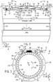
- FIG. 2 is a schematic side view of an embodiment of the moveable assembly 16 of FIG. 1 , illustrating the load 11 supported by the spreader bar 24 (e.g., coupled via load couplings 25), the spreader bar 24 coupled to the lift portion 26 via lift couplings 27, the rotational portion 28 coupled to the lift portion 26 via one or more couplings 76, and first framework 42 coupled to the rotational portion 28 via one or more couplings 78.
- the couplings 25, 27, 76, and 78 may include threaded fasteners (e.g., bolts and/or nuts), brackets, hooks that fit into slots, dovetail joints, threaded flanges, clamps, welded joints, or any combination thereof.
- the rotational portion 28 is disposed vertically above the lift portion 26. In some embodiments, the rotational portion 28 is disposed vertically below the lift portion 26.
- the rotational portion 28 is driven by the drive 17, 54 to cause rotation of the lift portion 26, the spreader bar 24, and the load 11 in opposite directions 62, 63 about the vertical axis 6.
- the lift portion 26 is driven by the drive 17, 56 to cause vertical movement of the lift portion 26, the spreader bar 24, and the load 11 in opposite vertical directions 64, 65 along the vertical axis 6.
- the first rail guided structure 34 (including the first framework 42, the rotational portion 28, the lift portion 26, the spreader bar 24, and the load 11) is driven to move along the first rails 36 via the drive 17, 50 and the transmission 19, 51 (e.g., shaft 66, as shown in FIG. 1 ).
- the shaft 66 may be coupled to a receptacle 80 (e.g., a threaded receptacle), such that rotation of the shaft 66 causes translation of the first rail guided structure 34 in the first horizontal direction 2 along the first rails 36.
- the first rails 36 have a C-shaped cross-section 82 (or C-shaped extrusion) configured to support the plurality of first wheels 46, such as a plurality of vertical wheels 84 and a plurality of horizontal wheels 86.
- the vertical wheels 84 are configured to provide vertical stabilization of the first rail guided structure 34
- the horizontal wheels 86 are configured to provide horizontal stabilization of the first rail guided structure 34.
- FIG. 3 is a perspective view of an embodiment of the rotational portion 28 of the moveable assembly 16 of FIGS. 1-2 .
- the rotational portion 28 may be coupled to a first framework 42.
- the rotational portion 28 may include a first portion 90 and a second portion 92 disposed in a nested arrangement, such as a coaxial or concentric arrangement with the portions 90 and 92 disposed about one another and a central axis 94.
- the first and second portions 90 and 92 may be concentric annular portions, wherein at least one rotates relative to the other.
- the first portion 90 comprises a fixed portion (e.g., a fixed housing or casing) and the second portion 92 comprises a rotational portion.
- the first and second portions 90 and 92 may be coupled together along an annular rail and/or bearing assembly 96, thereby blocking axial movement while allowing rotational movement between the portions 90 and 92.
- the first portion 90 (e.g., fixed portion) may be coupled to the first framework 42 via the plurality of couplings 78, which may include threaded fasteners (e.g., threaded receptacles, bolts, nuts, etc.), clamps, rods, receptacles, welds, or any combination thereof.
- the second portion 92 (e.g., rotational portion) may be coupled to the lift portion 26 via the plurality of couplings 76, which may include threaded fasteners (e.g., threaded receptacles, bolts, nuts, etc.), clamps, rods, receptacles, welds, or any combination thereof.
- the third transmission 19, 55 includes a first or drive gear 98 coupled to or integral with the third drive 17, 54, and a second or driven gear 100 coupled to or integral with the second portion 92 (e.g., rotational portion) of the rotational portion 28.
- the drive gear 98 may include a threaded shaft or worm
- the driven gear 100 may include a worm gear or annular gear having outwardly facing teeth.
- the third drive 17, 54 is controlled by the control system 20 to rotate the drive gear 98, which in turn drives rotation of the driven gear 100.
- the third transmission 19, 55 drives rotation of the lift portion 26, the spreader bar 24, and the load 11.
- the first portion 90 may be coupled to the first framework 42 in a fixed or stationary position, while the second portion 92 rotates in response to the third drive 17, 54 and third transmission 19, 55.
- the second portion 92 of the rotational portion 28 may be driven to rotate in the opposite directions 62 and 63 in a smooth continuous manner, in a stepwise manner (e.g., increments of 0.1, 1, 2, 3, 4, 5, or 10 degrees), or any combination thereof.
- the range of rotation may be 45, 60, 90, 180, 270, or 360 degrees, or any suitable rotational distance.
- the first and/or second portions 90 and 92 may be partially or entirely integrated with, recessed into, or housed by the first framework 42.
- the first portion 90 may include an outer housing wall 102 (e.g., sealed container) configured to contain and protect the second portion 92, the bearing assembly 96, and the gears 98 and 100, thereby blocking any ingress of debris, water, dirt, and/or other external contaminants.
- the first portion 90, the second portion 92, the bearing assembly 96, the wall 102, and/or the third drive 17, 54 may include a lubricant fitting 104 (e.g., a grease fitting) to provide lubricant (e.g., grease) for the rotational components.
- FIGS. 4-6 illustrate features of the lift portion 26 of the movable assembly 16.
- FIG. 4 is a schematic side view of an embodiment of the lift portion 26 of the moveable assembly 16 coupled to the spreader bar 24 of FIGS. 1-2 .
- the lift portion 26 may include a telescopic joint 110 that moves in the vertical direction 6.
- the telescopic joint 110 may be coupled to the lift portion 26 at a first end 106 by welding, brazing, a flange with connecting members, or any other suitable process.
- the telescopic joint 110 may include a plurality of concentric sleeves 112 (e.g., 2, 3, 4, 5, 6, 7, 8, 9, 10, or more) arranged concentrically around a longitudinal axis of the telescopic joint 110.
- Smaller concentric sleeves 112 may be nested within larger concentric sleeves 112 when the telescopic joint 110 is retracted.
- the concentric sleeves 112 may be cylindrical, square, rectangular, or any other suitable geometry.
- the concentric sleeves 112 may axially extend and retract relative to one another to translate the load 11 in the vertical direction 6.
- the concentric sleeves 112 may extend and retract in the vertical direction 6, in opposite directions 64 and 65 to translate the load 11 to various positions in response to the control system 20.
- the concentric sleeves 112 also may be sized (e.g., diameter, wall thickness, etc.) and spaced (e.g., clearance) to improve stability while lifting and lowering the load 11.
- the concentric sleeves 112 may generally block laterally movement of the lift portion 26 and the load 11 in the horizontal directions 2 and 4. Mechanical stops or protrusions may be disposed around the sides of the concentric sleeves 112 to control the extension and retraction of the concentric sleeves when they are translated.
- the inner and outer surfaces of the concentric sleeves 112 may be coated with a material such as grease to reduce the effect of friction between the concentric sleeves 112 when concentric sleeves move relative to one another.
- the fourth drive 17, 56 and fourth transmission 19, 57 may be utilized to translate the telescopic joint 110 in the vertical direction 6.
- the fourth transmission 19, 57 may include a variety lifting assemblies, such as an electrical chain hoist, an electrical wire rope hoist, a hydraulic winch, or other suitable lifting mechanism to lift and/or lower the load 11.
- the fourth transmission 19, 57 may include a hoist or winch system 114 having a spool 116 coupled to the fourth drive 17, 56, and a line 118 coiled around the spool 116 and coupled to the spreader bar 24 at the coupling 27 (e.g., lift coupling).
- the line 118 may include a cable, a chain, a rope, or any combination thereof, made of metal, fabric, plastic, etc.
- the coupling may include a plurality of mounting flanges or plates, such as a first plate 119 coupled to the end 108 of the telescopic joint 110 and a second plate 120 coupled to the spreader bar 24.
- the plates 119, 120 may be coupled together via threaded fasteners, welds, clamps, or any suitable joints.
- FIG. 5 is a schematic side view of an embodiment of the lift portion 26 of the moveable assembly 16 coupled to the spreader bar 24 of FIGS. 1-2 .
- the rotational portion 28 may include the first portion 90 and the second portion 92, wherein the second portion 92 may be coupled to the lift portion 26 via the plurality of couplings 76 (e.g., threaded fasteners, hooks, clamps, welds, etc.).
- the lift portion 26 includes opposite first and second plates 122 and 124 (e.g., upper and lower supports), which are spaced apart from one another in a substantially parallel arrangement and move toward and away from one another via the fourth drive 17, 56 and fourth transmission 19, 57.
- the first plate 122 is coupled to the second portion 92 of the rotation portion 28 via the couplings 76, while the second plate 124 is coupled to the spreader bar 24 via the couplings 27 (e.g., threaded fasteners, hooks, clamps, welds, etc.).
- the couplings 27 e.g., threaded fasteners, hooks, clamps, welds, etc.
- the lift portion 26 also includes a plurality of stabilizing guides 123 (e.g., vertical stabilizing guides), such as first, second, and third stabilizing guides 125, 126, and 127 coupled to the first plate 122.
- the stabilizing guides 123 may be coupled to the first plate 122 via fixed couplings (e.g., welded joints or one-piece construction), removable couplings (e.g., threaded joints, threaded fasteners, clamps, hooks, etc.), or any combination thereof.
- the stabilizing guides 123 may be vertically oriented shafts, rods, or structural supports, which generally extend along the vertical axis 6 in a parallel orientation relative to one another and a crosswise (e.g., perpendicular) orientation relative to the first and second plates 122, 124.
- the stabilizing guides 123 also may be offset from one another in a stabilizing arrangement 121, such as a triangular arrangement (as shown in FIG. 6 ).
- the second plate 124 is configured to move in opposite vertical directions 64, 65 along a length of the stabilizing guides 123.
- the second plate 124 includes a plurality of stabilizing guide supports or receptacles 128 (e.g., annular supports with bores), which are configured to receive the plurality of stabilizing guides 123 (e.g., stabilizing guides 125, 126, and 127).
- the stabilizing guides 123 are configured to slide in the vertical directions 64, 65 through the receptacles 128 during lifting and lowering.
- the stabilizing guides 123 and receptacles 128 may be cylindrical, elliptical, square, rectangular, or any other polygonal shape.
- the stabilizing guide supports or receptacles 128 may be coupled to the second plate 124 via fixed couplings (e.g., welded joints or one-piece construction), removable couplings (e.g., threaded joints, threaded fasteners, clamps, hooks, etc.), or any combination thereof.
- the illustrated stabilizing guide supports or receptacles 128 also protrude from the second plate 124 to provide a greater length and stability for the stabilizing guides 123 received therein.
- the stabilizing guide supports or receptacles 128 may include bushings, sleeves, cylindrical bearings, or any combination thereof.
- the stabilizing guide supports or receptacles 128 also may be offset from one another in a stabilizing arrangement 129 (as shown in FIG. 6 ), such as a triangular arrangement, to match the stabilizing arrangement 121 of the stabilizing guides 123.
- one or more of the stabilizing guides 123 may be disposed in the spreader bar 24 through a spreader bar slot 136, which extends lengthwise along the spreader bar 24 (e.g., along a centerline).
- the spreader bar 24 may include 1, 2, 3, 4, 5, 6, or more spreader bar slots 136 that receive corresponding stabilizing guides 123.
- the first stabilizing guide 123, 125 is disposed in the spreader bar slot 136, while the second stabilizing guide 123, 126 and the third stabilizing guide 123, 127 are disposed on opposite first and second sides 135 and 137 of the spreader bar 24.
- the placement of the stabilizing guides 123 both internally within the slot 136 of the spreader bar 24 and externally along the sides 135, 137 of the spreader bar 24 helps to provide additional stability during lifting and lowering of the spreader bar 24 and the load 11.
- the stabilizing guides 123 may extend a partial depth, a complete depth, or greater than the complete depth of the spreader bar 26 to provide stability.
- the first stabilizing guide 123, 125 and the second stabilizing guide 123, 126 can slide relative to spreader bar slot 136 on axis 4 so that is centered to different loads 11 center of gravity.
- the control system 20 is configured to selectively operate the fourth drive 17, 56 and fourth transmission 19, 57 to raise and lower the second plate 124 with receptacles 128, the spreader bar 24, and the load 11, while the first plate 122 and the stabilizing guides 123 generally remain stationary (e.g., no vertical movement).
- the stabilizing guide supports or receptacles 128 of the second plate 124 slide up and down the stabilizing guides 123, while the spreader bar 24 slides up and down the stabilizing guides 123 at the spreader bar slot 136 and opposite sides 135 and 137 of the spreader bar 24.
- the stabilizing guides 123 provide stability and lateral support, thereby resisting lateral movement, tilt, or pivoting away from the vertical axis 6.
- the fourth transmission 19, 57 may include a variety lifting assemblies, such as an electrical chain hoist, an electrical wire rope hoist, a hydraulic winch, or other suitable lifting mechanism to lift and/or lower the load 11.
- the fourth transmission 19, 57 may include a hoist or winch system 114 having a spool 116 coupled to the fourth drive 17, 56, and a line 118 coiled around the spool 116 and coupled to the spreader bar 24 at the coupling 27 (e.g., lift coupling such as a hook 130 in a receptacle 132).
- the line 118 may include a cable, a chain, a rope, or any combination thereof, made of metal, fabric, plastic, etc.
- the hoist or winch system 114 also may include one or more pulleys 134 to route the line 118 from the spool 116 to the coupling 27.
- FIG. 6 is a partial cutaway schematic view of an embodiment of the lift portion 26 taken within line 6-6 of FIG. 5 , illustrating the first stabilizing guide 123, 125 disposed in the slot 136 of the spreader bar 24 and the second and third stabilizing guides 123, 126, 127 disposed on the opposite sides 135, 137 of the spreader bar 24.
- FIG. 6 illustrates the second plate 124 from a plane between the first and second plates 122, 124, cut through the stabilizing guides 123, and looking downwardly on the second plate 124 and the spreader bar 24.
- the stabilizing guides 123 extend movably through the stabilizing guide supports or receptacles 128 in the triangular arrangements 121, 129, which helps to increase stability of the lift portion 26 during lifting and lowering.
- the first and/or second plates 122, 124 also may have a triangular shape as illustrated, or a rectangular shape, a circular shape, an oval shape, or a combination thereof.
- the first stabilizing guide 123, 125 is disposed on a first end portion (e.g., a tip portion or reduced width portion) of the second plate 124, while the second and third stabilizing guides 123, 126, 127 are both disposed at a longitudinal offset away from the first stabilizing guide 123, 125 on a second end portion (e.g., an enlarged width portion) of the second plate 124.
- the first stabilizing guide 123, 125 may be sized to fit closely within the slot 136 and the guide supports or receptacles 128 to improve stability, while leaving sufficient clearance to enable movement up and down in the vertical directions 64, 65.
- the second and third stabilizing guides 123, 126, 127 may be sized to fit closely within the guide supports or receptacles 128 and spaced closely about a width of the spreader bar spreader bar 24 to improve stability, while leaving sufficient clearance to enable movement up and down in the vertical directions 64, 65.
- the stabilizing guides 123 and the guide supports or receptacles 128 have a circular cross-section or cylindrical shape.
- the stabilizing guides 123 and the guide supports or receptacles 128 may be rectangular, square, triangular, oval, hexagonal, circular, or any combination thereof
- FIG. 7 is a schematic top view of an embodiment of the first rail guided structure 34 taken within line 7-7 of FIG. 2 , illustrating the rotational portion 28, the lift portion 26, and the plurality of wheels 46 disposed along the pair of first rails 36.
- the first framework 42 e.g., spider trolley
- the first framework 42 has a plurality of structural supports 138 diverging outwardly from the rotational portion 28 toward the pair of first rails 36 (e.g., first and second pairs of V-shaped structures defining an X-shaped structure).
- the first framework 42 supports a plurality of sets of wheels 46 on each of the pair of first rails 36, thereby helping to improve stability and movement of the first rail guided structure 34 along the first rails 36.
- each of the structural supports 138 may include a plurality of wheels 46, such as one or more vertical wheels 84 and one or more horizontal wheels 86, disposed in the adjacent first rail 36.
- one or more of the structural supports 138 may include the lock assembly 47, which may have a movable lock structure 139 that selectively extends into the first rail 36 as indicated by dashed lines, and selectively retracts out of the first rail 36 as indicated by solid lines.
- the control system 20 may be communicatively coupled to each of the lock assemblies 47, thereby selectively controlling actuation of the movable lock structures 139 via a drive (e.g., an electric drive, a fluid drive, a solenoid, or any combination thereof).
- a drive e.g., an electric drive, a fluid drive, a solenoid, or any combination thereof.
- the drive 17, 50 may rotate the threaded shaft 66 along a threaded receptacle 140, thereby driving the sliding support structure 68 as shown in FIG. 1 .
- the drive 17, 50 may rotate the threaded shaft 66 along the threaded receptacle 140, thereby driving the first rail guided structure 34 along the first rails 36 as shown by arrows 58, 59.
- FIG. 8 is a partial schematic top view of an embodiment of the second rail guided structure 38 taken within line 8-8 of FIG. 1 , illustrating a plurality of wheels 48 disposed along one of a pair of second rails 40.
- the second framework 44 has a plurality of structural supports 138 that extend to the second rails 40, wherein each support 138 may include a set of wheels 48 (e.g., one or more vertical wheels 84 and one or more horizontal wheels 86) to improve stability and movement of the second rail guided structure 38 along the second rails 40.
- one or more of the structural supports 138 may include the lock assembly 49, which may have a movable lock structure 139 that selectively extends into the second rail 40 as indicated by dashed lines, and selectively retracts out of the second rail 40 as indicated by solid lines.
- the control system 20 may be communicatively coupled to each of the lock assemblies 49, thereby selectively controlling actuation of the movable lock structures 139 via a drive (e.g., an electric drive, a fluid drive, a solenoid, or any combination thereof).
- a drive e.g., an electric drive, a fluid drive, a solenoid, or any combination thereof.
- the drive 17, 52 may rotate the transmission 19, 53 which can be also another threaded shaft 74 along a threaded receptacle 141, thereby driving the second frame or support structure 44 (as shown in FIG. 1 ) to a translational movement as shown with arrows 60, 61.
- FIGS. 9-11 are diagrams of embodiments of the rail guided structure 34, 38, the drive system 18, and the transmission 19 as illustrated in FIGS. 1-8 .
- the drive system 18 e.g., drive 17
- the transmission 19 may include a track, a guide, a rod or shaft, a threaded shaft, a gear, a geared structure, a rack and pinion assembly, a worm and worm gear assembly, a piston and cylinder assembly, a chain, a cable, or any combination thereof.
- the drive system 18 may create rotational or linear motion, which may be used to drive the transmission 19 via rotational motion, axial motion, or a combination thereof.
- the drive 17 may include a fluid drive (e.g., a pneumatic or hydraulic drive), an electric drive or motor, or any combination thereof.
- FIG. 9 is a diagram of an embodiment of the first and/or second rail guided structure 34, 38 and the drive system 18 having the drive 17 coupled to a rack and pinion assembly 142.
- the rack and pinion assembly 142 includes a linear gear or rack 144 and a circular gear or pinion 146 coupled to the drive 17 of the drive system 18.
- the drive 17 is configured to rotate the pinion 146, which in turn causes movement of the rack 144 in opposite first and second directions 147 depending on the direction of rotation.
- the rack 144 is coupled to the rail guided structure 34, 38, and thus movement of the rack 144 causes movement of the rail guided structure 34, 38 in the directions 147.
- FIG. 10 is a diagram of an embodiment of the first and/or second rail guided structure 34, 38 and the drive system 18 having a fluid drive 148 with a motor 150 (e.g., an electric motor) and a pump 152 driven by the motor 150, and the transmission 19 having a fluid driven assembly 153 driven by fluid from the pump 152.
- the fluid driven assembly 153 includes a piston-cylinder assembly 154 fluidly coupled to the pump 152.
- the piston-cylinder assembly 154 includes a piston 156 disposed in a cylinder 158, wherein the piston 156 is further coupled to a shaft 159.
- the controller 21 may control the motor 150 to drive the pump 152, which in turn pumps a fluid (e.g., liquid or gas) into the cylinder 158 of the piston-cylinder assembly 154.
- the fluid then drives the piston 154 to move in one of the directions 147, thereby driving the rail guided structure 34, 38 in one of the directions 147.
- fluid pumped into the right hand side of the cylinder 158 causes the piston 154, the shaft 159, and the rail guided structure 34, 38 to move in the leftward direction 147.
- fluid pumped into the left hand side of the cylinder 158 causes the piston 154, the shaft 159, and the rail guided structure 34, 38 to move in the rightward direction 147.
- the controller 21 may be configured to vary the speed of the motor 150 and pump 152, thereby varying the speed of movement of the piston 154 and rail guided structure 34, 38.
- the controller 21 may operate the fluid drive 148 at a first speed during a first stage of movement, a second speed during a second stage of movement, and a third speed during a third stage of movement, wherein the first, second, and third speeds are progressively greater or lesser than one another.
- FIG. 11 is a diagram of an embodiment of the first and/or second rail guided structure 34, 38 and the drive system 18 having the drive 17 coupled to a rotary screw or threaded shaft 160 of the transmission 19.
- the shaft 160 may be threaded into mating threads 162 (e.g., threaded receptacle) in the rail guided structure 34, 38, such that rotation 161 of the shaft 160 causes axial movement of the rail guided structure 34, 38 in one of the opposite directions 147.
- the drive 17 may include an electric motor, a fluid drive, or any combination thereof, configured to rotate the shaft 160.
- the transmission 19 may include a worm and worm gear assembly.
- the drive system 18 also may include a plurality of bearings 164 disposed about the threaded shaft 160, e.g., in non-threaded portions of the shaft 160.
- a load moving machine 12 having a frame 14 and a movable assembly 16 coupled to the frame 14, wherein the moveable assembly 16 is configured to move the load 11 in a plurality of directions (e.g., first and second horizontal directions, vertical directions, and rotational directions about one or more axes). These four degrees of freedom enable the load 11 to be balanced, be lifted, lowered, moved, or otherwise translated to dynamically move the load 11.
- the load moving machine 12 also includes a plurality of stabilizing structures to help resist undesired movement, rotation, tilting, pivoting, or any combination thereof, during a controlled movement by the drive system 18, the transmission 19, and the control system 20.
Landscapes
- Engineering & Computer Science (AREA)
- Mechanical Engineering (AREA)
- Types And Forms Of Lifts (AREA)
- Transmission Devices (AREA)
Abstract
Description
- The subject matter disclosed herein relates to lifting of loads, such as heavy machinery.
- A variety of industrial and commercial applications may use heavy machinery, such as generators and turbomachinery (e.g., turbines, compressors, and pump). The heavy machinery may be moved for many reasons, such as initial installation, servicing, or replacement. Unfortunately, the heavy machinery may be installed in locations that are difficult to access, moving or instable, and/or lack space for cranes. For example, the heavy machinery may be installed in ships. The heavy machinery also may be difficult to move due to variations in weight, size, shape, center of gravity, or other characteristics. As a result, the heavy machinery may be difficult to move.
- Certain embodiments commensurate in scope with the originally claimed invention are summarized below. These embodiments are not intended to limit the scope of the claimed invention, but rather these embodiments are intended only to provide a brief summary of possible forms of the invention. Indeed, the invention may encompass a variety of forms that may be similar to or different from the embodiments set forth below.
- In a first embodiment, a system includes a load moving machine, including a frame and a movable assembly coupled to the frame. The movable assembly includes a lift portion, a rotational portion, a first translational portion, and a second translational portion.
- In a second embodiment, a system includes a load moving machine including a movable assembly coupled to a frame. The movable assembly includes a spreader bar coupled having one or more load couplings, a lift portion coupled to the spreader bar, a rotational portion coupled to the lift portion, a first translational portion, and a second translational portion. The lift portion includes a first drive configured to raise and lower the spreader bar in a vertical direction. The rotational portion includes a second drive configured to rotate the lift portion and the spreader bar. The first translational portion includes a third drive configured to translate the rotational portion, the lift portion, and the spreader bar in a first horizontal direction. The second translational portion includes a fourth drive configured to translate the rotational portion, the lift portion, and the spreader bar in a second horizontal direction crosswise to the first horizontal direction.
- In a third embodiment, a method includes controlling movement of a lift portion, a rotational portion, a first translational portion, and a second translational portion of a movable assembly coupled to a frame of a load moving machine to move a load.
- These and other features, aspects, and advantages of the present invention will become better understood when the following detailed description is read with reference to the accompanying drawings in which like characters represent like parts throughout the drawings, wherein:
-
FIG. 1 is a schematic view of an embodiment of a load moving system having a load moving machine with a moveable assembly disposed in a frame, wherein the moveable assembly has a lift portion, a rotational portion, a first translational portion with a first rail guided structure, and a second translational portion with a second rail guided structure; -
FIG. 2 is a schematic side view of an embodiment of the load moving system ofFIG. 1 , illustrating the moveable assembly having the rotational portion and the lift portion coupled to a spreader bar, which supports one or more loads; -
FIG. 3 is a schematic cross-sectional top view of an embodiment of the rotational portion of the moveable assembly ofFIGS. 1-2 ; -
FIG. 4 is a schematic side view of an embodiment of the lift portion of the moveable assembly coupled to the spreader bar ofFIGS. 1-2 ; -
FIG. 5 is a schematic side view of an embodiment of the lift portion of the moveable assembly coupled to the spreader bar ofFIGS. 1-2 ; -
FIG. 6 is a partial cutaway schematic view of an embodiment of the lift portion taken within line 6-6 ofFIG. 5 , illustrating a first stabilizing guide disposed in a slot of the spreader bar and second and third stabilizing guides disposed on opposite sides of the spreader bar; -
FIG. 7 is a schematic top view of an embodiment of the first rail guided structure taken within line 7-7 ofFIG. 2 , illustrating the rotational portion, the lift portion, and a plurality of wheels disposed along a pair of first rails; -
FIG. 8 is a partial schematic top view of an embodiment of the second rail guided structure taken within line 8-8 ofFIG. 1 , illustrating a plurality of wheels disposed along one of a pair of second rails; -
FIG. 9 is a diagram of an embodiment of the first and/or second rail guided structure and a drive system having a drive coupled to a rack and pinion; -
FIG. 10 is a diagram of an embodiment of the first and/or second rail guided structure and a drive system having a motor, a pump, and a fluid driven assembly; and -
FIG. 11 is a diagram of an embodiment of the first and/or second rail guided structure and a drive system having a drive coupled to a rotary screw. - One or more specific embodiments of the present invention will be described below. In an effort to provide a concise description of these embodiments, all features of an actual implementation may not be described in the specification. It should be appreciated that in the development of any such actual implementation, as in any engineering or design project, numerous implementation-specific decisions must be made to achieve the developers' specific goals, such as compliance with system-related and business-related constraints, which may vary from one implementation to another. Moreover, it should be appreciated that such a development effort might be complex and time consuming, but would nevertheless be a routine undertaking of design, fabrication, and manufacture for those of ordinary skill having the benefit of this disclosure.
- When introducing elements of various embodiments of the present invention, the articles "a," "an," "the," and "said" are intended to mean that there are one or more of the elements. The terms "comprising," "including," and "having" are intended to be inclusive and mean that there may be additional elements other than the listed elements.
- The disclosed embodiments are directed toward load moving systems that facilitate movement of a load (e.g., heavy machinery) with at least four degrees of freedom while stabilizing (e.g., balancing) the load. For example, the load may include turbomachinery (e.g., a turbine, a compressor, or a pump), a generator, or a reciprocating internal combustion engine. As discussed in detail below, embodiments of the load moving systems may enable horizontal movement in first and second crosswise directions via respective first and second rail guided structures, vertical movement via a lift portion, and rotational movement via a rotational portion. Altogether, these systems enable four degrees of freedom with controlled movement and stability to ensure protection of the load and the surrounding structures (e.g., deck of a ship).
- The first and second rail guided structures may be movably coupled to first and second pairs of rails disposed in a frame, wherein each rail guided structure may include a plurality of wheels (e.g., horizontal and vertical wheels) disposed in each of the rails. In some embodiments, the first rail guided structure may be movably mounted in the second rail guided structure. For example, the second rail guided structure may include the first rails supporting the wheels of the first rail guided structure. The second rail guided structure may be movably mounted in the frame. For example, the frame may include the second rails supporting the wheels of the second rail guided structure. The first and second rail guided structures may be coupled to a drive system (e.g., electric or fluid drive). For example, the drive system may include a liquid or gas driven piston and shaft assembly, an electrical motor driven shaft, a rack and pinion system, a rotary screw system, or any combination thereof. The first rail guided structure may also include the rotational portion, the lift portion, and a spreader bar configured to couple to the load.
- The rotational portion may include a drive system (e.g., electric or fluid drive) configured to rotate a first portion relative to a second portion, wherein the first portion is a rotary portion and the second portion is a stationary portion. For example, the first and second portions may be coaxial or concentric with one another, and the drive system may be configured to rotate the first portion externally about or internally within the second portion. The first portion also may be coupled to the lift portion and/or the spreader bar. The lift portion may include a telescopic joint having a plurality of concentric sleeves configured to extend and retract relative to one another in response to a drive system (e.g., electric or fluid drive, winch, cable and pulley, etc.). The lift portion may include one or more stabilizing guides, such as first, second, and third stabilizing guides, coupled to a first plate and movable through a second plate. For example, the first stabilizing guide may be disposed in a slot in the spreader bar, while the second and third stabilizing guides may be disposed on opposite sides of the stabilizing guide.
- Turning now to the drawings,
FIG. 1 is a schematic view of an embodiment of aload moving system 10 configured to move aload 11 in a plurality of translational/linear directions and a plurality of rotational directions (e.g., horizontal directions, vertical directions, and rotational directions about one or more axes). For purposes of this discussion, reference may be made to a first horizontal axis ordirection 2, a second horizontal axis ordirection 4 disposed crosswise (e.g., substantially perpendicular) to thefirst axis 2, a vertical axis ordirection 6, and a rotational orcircumferential direction 8 disposed about thevertical axis 6. As used herein, the terms horizontal and vertical may include some degree of deviation (e.g., 5, 10, 15, 20, 25, or 30 degrees) from horizontal and vertical, and the terms may be used for convenience to indicate that the axes, directions, and/or planes are generally crosswise (e.g., substantially perpendicular) to one another. Theload moving system 10 is configured to move theload 11, in a controlled and stabilized manner, in opposite directions along the firsthorizontal axis 2, the secondhorizontal axis 4, thevertical axis 6, and therotational direction 8. - The
load moving system 10 may be used in a variety of applications, such as moving theload 11 in a vessel at sea, an automotive assembly line, an industrial plant, a power plant, a chemical plant, or any combination thereof. Theload 11 may include turbomachinery (e.g., a turbine, a compressor, or a pump), a generator, a reciprocating internal combustion engine, other heavy machinery, or any combination thereof. Theload 11 also may include a vehicle or vehicle components, a vessel, a combustion system, a reactor, or engine support components (e.g., filter units, exhaust stack, lubrication systems, etc.). In certain embodiments, theload 11 may include a gas turbine engine having a compressor section with one or more compression stages, a combustor section with one or more combustors, and a turbine section with one or more turbine stages. - The
load moving system 10 includes aload moving machine 12 having aframe 14 supporting amoveable assembly 16. Theframe 14 includes a plurality of structural supports extending in thedirections load 11. Themoveable assembly 16 is configured to support, lift, and move theload 11 in thevarious directions frame 14. Theload moving system 10 includes adrive system 18 coupled to themoveable assembly 16, wherein thedrive system 18 comprises a plurality ofdrives 17 andtransmissions 19 configured to drive movement in thevarious directions - The
drives 17 of thedrive system 18 may include an electric drive (e.g., an electric motor), a fluid drive (e.g., a liquid or hydraulic drive and/or a gas or pneumatic drive), or a combination thereof. The fluid drive may include a piston driven assembly having a piston disposed in a cylinder. Thetransmissions 19 may include a translational or rotational shaft, a gear box or gear assembly, a telescopic assembly having a plurality of concentric sleeves or shafts that extend and retract relative to one another, a cable and pulley system having a winch, a worm gear assembly, a planetary gear assembly, a rack and pinion gear assembly, or any combination thereof. Thedrive system 18 may include anindependent drive 17 andtransmission 19 for movement in each of thedirections drive system 18 may sharedrives 17 and/ortransmissions 19 for movement in two or more of thedirections - The
drive system 18 is coupled to acontrol system 20, which may include one or more controllers 21 (e.g., electronic controllers) having aprocessor 22 and memory 23 (e.g., random access memory, read only memory, flash memory, volatile or non-volatile memory, hard drive, etc.). Thecontrollers 21 are configured to store instructions in thememory 23 and execute the instructions via theprocessor 22 to control operation of thedrive system 18. In particular, thecontrollers 21 may execute instructions to control thedrives 17 to balance theload 11 and to provide a stable rate of movement in thedirections load 11, the stability of the locations (e.g., mounted on a ship), and so forth. For example, thecontrollers 21 are configured to control the movement of theload 11 via themoveable assembly 16, including alift portion 26, arotational portion 28, a firsttranslational portion 30, and a secondtranslational portion 32. Thecontrol system 20 may communicatively couple to various sensors throughout theload moving system 10 and use sensor feedback to help improve the movement of theload 11. The sensors may include speed sensors, accelerometers, wind sensors, humidity sensors, vibration sensors, noise or acoustic sensors, force or resistance sensors, load level sensors, load tilt or angle sensors, load weight sensors, location stability sensors (e.g., motion caused by waves), water sensors (e.g., sense rainfall or water in vicinity of lifting area), or any combination thereof. Thecontrol system 20 also may include a user interface or control panel having a display (e.g., LED, LCD, or touch screen display), user inputs (e.g., buttons, keypad or keyboard, touchpad, mouse, etc.), outputs or alerts (e.g., audio or visual alarms), or any combination thereof. - As described in further detail below, the
moveable assembly 16 may include aspreader bar 24, thelift portion 26, therotational portion 28, the firsttranslational portion 30, and the secondtranslational portion 32. The firsttranslational portion 30 may include a first rail guidedstructure 34 disposed along one or more first rails 36 (e.g., first and second parallel rails 36), while the secondtranslational portion 32 may include a second rail guidedstructure 38 disposed along one or more second rails 40 (e.g., first and second parallel rails 40). In certain embodiments, the first and secondtranslational portions 30 and 32 (e.g., first and second rail guidedstructures 34 and 38) may be independent and separate from one another. In the illustrated embodiment, the first and secondtranslational portions 30 and 32 (e.g., first and second rail guidedstructures 34 and 38) are dependent on one another in a nested arrangement, wherein the first rail guidedstructure 34 is configured to move along the second rail guidedstructure 38, while the second rail guidedstructure 38 is configured to move along theframe 14. As a result, parts of the second rail guidedstructure 38 support the first rail guidedstructure 34. - In the illustrated embodiment, the first rail guided
structure 34 includes a first framework or support structure 42 (e.g., a spider trolley), while the second rail guidedstructure 38 includes a second framework orsupport structure 44. Thefirst framework 42 of the first rail guidedstructure 34 supports theload 11, thespreader bar 24, thelift portion 26, and therotational portion 28, wherein theelements spreader bar 24 may be coupled to theload 11 via one ormore load couplings 25, thelift portion 26 may be coupled to thespreader bar 24 via one or more lift couplings 27 (as shown inFIG. 2 ), therotational portion 28 may be coupled to thelift portion 26 via one or more couplings and/or stabilizing guides 76 (as shown inFIG 2 ), and therotational portion 28 may be coupled to thefirst framework 42 via one or more couplings 78 (as shown inFIG 2 ). Thefirst framework 42 of the first rail guidedstructure 34 also includes a plurality of wheels 46 (e.g., horizontal and vertical wheels) configured to roll along thefirst rails 36 and one or moremovable lock assemblies 47 to selectively block movement along the first rails 36. For example, thecontrol system 20 may be coupled to actuator controlledlock assemblies 47 that rotate and/or extend and retract a lock or stop structure between a locked position and an unlocked position relative to the first rails 36. In the illustrated embodiment, thefirst rails 36 are coupled to, integrated with, and/or part of thesecond framework 44. For example, parallel beams of thesecond framework 44 may include a C-shaped cross-section to define the first rails 36. In the illustrated embodiment, thefirst rails 36 are oriented along or parallel with the firsthorizontal axis 2. Thesecond framework 44 of the second rail guidedstructure 38 supports the first rail guidedstructure 34, and thus supports theload 11, thespreader bar 24, thelift portion 26, therotational portion 28, and thefirst framework 42. Thesecond framework 44 of the second rail guidedstructure 38 also includes a plurality of wheels 48 (e.g.,vertical wheels 84 andhorizontal wheels 86, as shown inFIG. 2 ) configured to roll along thesecond rails 40 and one or moremovable lock assemblies 49 to selectively block movement along the second rails 40. For example, thecontrol system 20 may be coupled to actuator controlledlock assemblies 49 that rotate and/or extend and retract a lock or stop structure between a locked position and an unlocked position relative to the second rails 40. In the illustrated embodiment, thesecond rails 40 are coupled to, integrated with, and/or part of theframe 14. For example, parallel beams of theframe 14 may include a C-shaped cross-section to define the second rails 40. In the illustrated embodiment, thesecond rails 40 are oriented along or parallel with the secondhorizontal axis 4. As a result, the first andsecond rails - In certain embodiments, the
control system 20 is configured to simultaneously, sequentially, dependently, and/or independently control movement of themoveable assembly 16 via afirst drive first transmission second drive second transmission third drive third transmission fourth drive fourth transmission first drive first transmission structure 34 to selectively translate (e.g., linearly move) the first rail guidedstructure 34 along thefirst rails 36 in opposite first andsecond directions horizontal axis 2. By further example, thesecond drive second transmission structure 38 to selectively translate (e.g., linearly move) the second rail guidedstructure 38 along thesecond rails 40 in opposite first andsecond directions horizontal axis 4. By further example, thethird drive third transmission rotational portion 28, thelift portion 26, thespreader bar 24, and/or theload 11 to selectively rotate thesecomponents second directions vertical axis 6. By further example, thefourth drive fourth transmission lift portion 26, thespreader bar 24, and/or the load 11 (and optionally the rotational portion 28) to selectively translate (e.g., linearly move) thesecomponents second directions 64, 65 (as shown inFIG. 2 ) along thevertical axis 6. Again, thecontrol system 20 may be configured to control thesedrives 17 to cause movements simultaneously, sequentially, dependently, and/or independently to provide a desired stable movement of theload 11. - As discussed in detail below, each of the
drives 17 andtransmissions 19 may have a variety of structures and components to induce movement of themoveable assembly 16 in the desired directions. For example, thefirst transmission structure 34 and/or theframe 14, such that rotation of theshaft 66 causes translational motion of the first rail guidedstructure 34. However, as discussed in detail below with reference toFIGS. 9-11 , thefirst transmission structure 34 in response to thefirst drive first drive support structure 68, which is slidingly mounted in and moves linearly along a pair of third rails 70 (or sliding guide supports) in opposite first andsecond directions first drive first transmission structure 34 along thefirst rails 36 while moving the slidingsupport structure 68 along the third rails 70 (e.g., between afirst position 71 shown in dashed lines and asecond position 72 shown in solid lines). In the illustrated embodiment, the slidingsupport structure 68 may first move at least partially or entirely along the length of thethird rails 70 from thefirst position 71 to thesecond position 72 while the first rail guidedstructure 34 is locked in position relative to thefirst rails 36 via thelock assemblies 47. For example, while the slidingsupport structure 68 is disposed in thefirst position 71, thecontrol system 20 may selectively actuate thelock assemblies 47 to engage the first rails 36 (e.g., extension of lock structures), thereby securing the first rail guidedstructure 34 in position. Once thestructure 34 is secured in position, thefirst drive first transmission shaft 66 relative to the first rail guidedstructure 34, thereby driving the slidingsupport structure 68 from thefirst position 71 to thesecond position 72. Once thestructure 68 is in thesecond position 72, thecontrol system 20 may selectively actuate thelock assemblies 47 to disengage the first rails 36 (e.g., retraction of lock structures), thereby releasing and allowing free movement of the first rail guidedstructure 34 along the first rails 36. In addition, thecontrol system 20 may selectively actuatelock assemblies 73 to engage the third rails 70 (e.g., extension of lock structures), thereby locking and blocking free movement of the slidingsupport structure 68 along thethird rails 70. At this point, thecontrol system 20 may selectively actuate thefirst drive shaft 66 relative to the first rail guidedstructure 34, thereby driving movement of the first rail guidedstructure 34 along thefirst rails 36 in thefirst direction 59. Thecontrol system 20 also may operate thefirst drive lock assemblies 47, and thelock assemblies 73 in the reverse order to move the first rail guidedstructure 34 in thesecond direction 58. Although a specific controlled procedure has been described for movement of the first rail guidedstructure 34, any simultaneous or sequential movements of the first rail guidedstructure 34 and the slidingsupport structure 68 may be implemented to cause movement of theload 11 coupled to thespreader bar 24. - In certain embodiments, the
second transmission structure 38 and/or theframe 14, such that rotation of theshaft 74 causes translational motion of the second rail guidedstructure 38. Again, thecontrol system 20 may selectively actuatelock assemblies 49 to engage the second rails 40 (e.g., extension of lock structures) or disengage the second rails 40 (e.g., retraction of lock structures), thereby selectively blocking or enabling free movement of the second rail guidedstructure 38 along the second rails 40. The lock structures may include a locking peg that selectively moves in and out of a lock housing, thereby extending and retracting the locking peg relative to the respective rails. As discussed in detail below with reference toFIGS. 9-11 , thesecond transmission structure 38 in response to thesecond drive fourth transmissions spreader bar 24, and thus theload 11. Embodiments of thesetransmissions FIGS. 2-6 . -
FIG. 2 is a schematic side view of an embodiment of themoveable assembly 16 ofFIG. 1 , illustrating theload 11 supported by the spreader bar 24 (e.g., coupled via load couplings 25), thespreader bar 24 coupled to thelift portion 26 vialift couplings 27, therotational portion 28 coupled to thelift portion 26 via one ormore couplings 76, andfirst framework 42 coupled to therotational portion 28 via one ormore couplings 78. Thecouplings rotational portion 28 is disposed vertically above thelift portion 26. In some embodiments, therotational portion 28 is disposed vertically below thelift portion 26. Therotational portion 28 is driven by thedrive lift portion 26, thespreader bar 24, and theload 11 inopposite directions vertical axis 6. Thelift portion 26 is driven by thedrive lift portion 26, thespreader bar 24, and theload 11 in oppositevertical directions vertical axis 6. The first rail guided structure 34 (including thefirst framework 42, therotational portion 28, thelift portion 26, thespreader bar 24, and the load 11) is driven to move along thefirst rails 36 via thedrive transmission 19, 51 (e.g.,shaft 66, as shown inFIG. 1 ). For example, theshaft 66 may be coupled to a receptacle 80 (e.g., a threaded receptacle), such that rotation of theshaft 66 causes translation of the first rail guidedstructure 34 in the firsthorizontal direction 2 along the first rails 36. The first rails 36 have a C-shaped cross-section 82 (or C-shaped extrusion) configured to support the plurality offirst wheels 46, such as a plurality ofvertical wheels 84 and a plurality ofhorizontal wheels 86. Thevertical wheels 84 are configured to provide vertical stabilization of the first rail guidedstructure 34, while thehorizontal wheels 86 are configured to provide horizontal stabilization of the first rail guidedstructure 34. -
FIG. 3 is a perspective view of an embodiment of therotational portion 28 of themoveable assembly 16 ofFIGS. 1-2 . As described above, therotational portion 28 may be coupled to afirst framework 42. Therotational portion 28 may include afirst portion 90 and asecond portion 92 disposed in a nested arrangement, such as a coaxial or concentric arrangement with theportions central axis 94. For example, the first andsecond portions first portion 90 comprises a fixed portion (e.g., a fixed housing or casing) and thesecond portion 92 comprises a rotational portion. The first andsecond portions assembly 96, thereby blocking axial movement while allowing rotational movement between theportions first framework 42 via the plurality ofcouplings 78, which may include threaded fasteners (e.g., threaded receptacles, bolts, nuts, etc.), clamps, rods, receptacles, welds, or any combination thereof. Likewise, the second portion 92 (e.g., rotational portion) may be coupled to thelift portion 26 via the plurality ofcouplings 76, which may include threaded fasteners (e.g., threaded receptacles, bolts, nuts, etc.), clamps, rods, receptacles, welds, or any combination thereof. In the illustrated embodiment, thethird transmission gear 98 coupled to or integral with thethird drive gear 100 coupled to or integral with the second portion 92 (e.g., rotational portion) of therotational portion 28. For example, thedrive gear 98 may include a threaded shaft or worm, while the drivengear 100 may include a worm gear or annular gear having outwardly facing teeth. In operation, thethird drive control system 20 to rotate thedrive gear 98, which in turn drives rotation of the drivengear 100. As the drivengear 100 rotates, thethird transmission lift portion 26, thespreader bar 24, and theload 11. Thefirst portion 90 may be coupled to thefirst framework 42 in a fixed or stationary position, while thesecond portion 92 rotates in response to thethird drive third transmission control system 20, thesecond portion 92 of therotational portion 28 may be driven to rotate in theopposite directions second portions first framework 42. Thefirst portion 90 may include an outer housing wall 102 (e.g., sealed container) configured to contain and protect thesecond portion 92, the bearingassembly 96, and thegears first portion 90, thesecond portion 92, the bearingassembly 96, thewall 102, and/or thethird drive -
FIGS. 4-6 illustrate features of thelift portion 26 of themovable assembly 16. For example,FIG. 4 is a schematic side view of an embodiment of thelift portion 26 of themoveable assembly 16 coupled to thespreader bar 24 ofFIGS. 1-2 . Thelift portion 26 may include a telescopic joint 110 that moves in thevertical direction 6. The telescopic joint 110 may be coupled to thelift portion 26 at afirst end 106 by welding, brazing, a flange with connecting members, or any other suitable process. The telescopic joint 110 may include a plurality of concentric sleeves 112 (e.g., 2, 3, 4, 5, 6, 7, 8, 9, 10, or more) arranged concentrically around a longitudinal axis of the telescopic joint 110. Smallerconcentric sleeves 112 may be nested within largerconcentric sleeves 112 when the telescopic joint 110 is retracted. Theconcentric sleeves 112 may be cylindrical, square, rectangular, or any other suitable geometry. Theconcentric sleeves 112 may axially extend and retract relative to one another to translate theload 11 in thevertical direction 6. Theconcentric sleeves 112 may extend and retract in thevertical direction 6, inopposite directions load 11 to various positions in response to thecontrol system 20. Theconcentric sleeves 112 also may be sized (e.g., diameter, wall thickness, etc.) and spaced (e.g., clearance) to improve stability while lifting and lowering theload 11. For example, theconcentric sleeves 112 may generally block laterally movement of thelift portion 26 and theload 11 in thehorizontal directions concentric sleeves 112 to control the extension and retraction of the concentric sleeves when they are translated. The inner and outer surfaces of theconcentric sleeves 112 may be coated with a material such as grease to reduce the effect of friction between theconcentric sleeves 112 when concentric sleeves move relative to one another. Thefourth drive fourth transmission vertical direction 6. Thefourth transmission load 11. For example, thefourth transmission winch system 114 having aspool 116 coupled to thefourth drive line 118 coiled around thespool 116 and coupled to thespreader bar 24 at the coupling 27 (e.g., lift coupling). Theline 118 may include a cable, a chain, a rope, or any combination thereof, made of metal, fabric, plastic, etc. The coupling may include a plurality of mounting flanges or plates, such as afirst plate 119 coupled to theend 108 of the telescopic joint 110 and asecond plate 120 coupled to thespreader bar 24. Theplates -
FIG. 5 is a schematic side view of an embodiment of thelift portion 26 of themoveable assembly 16 coupled to thespreader bar 24 ofFIGS. 1-2 . As described above, therotational portion 28 may include thefirst portion 90 and thesecond portion 92, wherein thesecond portion 92 may be coupled to thelift portion 26 via the plurality of couplings 76 (e.g., threaded fasteners, hooks, clamps, welds, etc.). In the illustrated embodiment, thelift portion 26 includes opposite first andsecond plates 122 and 124 (e.g., upper and lower supports), which are spaced apart from one another in a substantially parallel arrangement and move toward and away from one another via thefourth drive fourth transmission first plate 122 is coupled to thesecond portion 92 of therotation portion 28 via thecouplings 76, while thesecond plate 124 is coupled to thespreader bar 24 via the couplings 27 (e.g., threaded fasteners, hooks, clamps, welds, etc.). - The
lift portion 26 also includes a plurality of stabilizing guides 123 (e.g., vertical stabilizing guides), such as first, second, and third stabilizingguides first plate 122. For example, the stabilizingguides 123 may be coupled to thefirst plate 122 via fixed couplings (e.g., welded joints or one-piece construction), removable couplings (e.g., threaded joints, threaded fasteners, clamps, hooks, etc.), or any combination thereof. The stabilizing guides 123 may be vertically oriented shafts, rods, or structural supports, which generally extend along thevertical axis 6 in a parallel orientation relative to one another and a crosswise (e.g., perpendicular) orientation relative to the first andsecond plates arrangement 121, such as a triangular arrangement (as shown inFIG. 6 ). - In the illustrated embodiment, the
second plate 124 is configured to move in oppositevertical directions second plate 124 includes a plurality of stabilizing guide supports or receptacles 128 (e.g., annular supports with bores), which are configured to receive the plurality of stabilizing guides 123 (e.g., stabilizingguides vertical directions receptacles 128 during lifting and lowering. The stabilizing guides 123 andreceptacles 128 may be cylindrical, elliptical, square, rectangular, or any other polygonal shape. In the illustrated embodiment, the stabilizing guide supports orreceptacles 128 may be coupled to thesecond plate 124 via fixed couplings (e.g., welded joints or one-piece construction), removable couplings (e.g., threaded joints, threaded fasteners, clamps, hooks, etc.), or any combination thereof. The illustrated stabilizing guide supports orreceptacles 128 also protrude from thesecond plate 124 to provide a greater length and stability for the stabilizingguides 123 received therein. For example, the stabilizing guide supports orreceptacles 128 may include bushings, sleeves, cylindrical bearings, or any combination thereof. The stabilizing guide supports orreceptacles 128 also may be offset from one another in a stabilizing arrangement 129 (as shown inFIG. 6 ), such as a triangular arrangement, to match the stabilizingarrangement 121 of the stabilizing guides 123. - As depicted, one or more of the stabilizing
guides 123 may be disposed in thespreader bar 24 through aspreader bar slot 136, which extends lengthwise along the spreader bar 24 (e.g., along a centerline). For example, thespreader bar 24 may include 1, 2, 3, 4, 5, 6, or morespreader bar slots 136 that receive corresponding stabilizing guides 123. In the illustrated embodiment, the first stabilizingguide spreader bar slot 136, while the second stabilizingguide guide second sides spreader bar 24. The placement of the stabilizingguides 123 both internally within theslot 136 of thespreader bar 24 and externally along thesides spreader bar 24 helps to provide additional stability during lifting and lowering of thespreader bar 24 and theload 11. The stabilizing guides 123 may extend a partial depth, a complete depth, or greater than the complete depth of thespreader bar 26 to provide stability. Moreover, the first stabilizingguide guide spreader bar slot 136 onaxis 4 so that is centered todifferent loads 11 center of gravity. - In the illustrated embodiment, the
control system 20 is configured to selectively operate thefourth drive fourth transmission second plate 124 withreceptacles 128, thespreader bar 24, and theload 11, while thefirst plate 122 and the stabilizingguides 123 generally remain stationary (e.g., no vertical movement). During this movement, the stabilizing guide supports orreceptacles 128 of thesecond plate 124 slide up and down the stabilizingguides 123, while thespreader bar 24 slides up and down the stabilizingguides 123 at thespreader bar slot 136 andopposite sides spreader bar 24. In this manner, the stabilizingguides 123 provide stability and lateral support, thereby resisting lateral movement, tilt, or pivoting away from thevertical axis 6. Thefourth transmission load 11. For example, thefourth transmission winch system 114 having aspool 116 coupled to thefourth drive line 118 coiled around thespool 116 and coupled to thespreader bar 24 at the coupling 27 (e.g., lift coupling such as ahook 130 in a receptacle 132). Theline 118 may include a cable, a chain, a rope, or any combination thereof, made of metal, fabric, plastic, etc. The hoist orwinch system 114 also may include one ormore pulleys 134 to route theline 118 from thespool 116 to thecoupling 27. - The orientation of the components of the
lift portion 26 and therotational portion 28 may be further understood with respect toFIGS. 6 and 7. FIG. 6 is a partial cutaway schematic view of an embodiment of thelift portion 26 taken within line 6-6 ofFIG. 5 , illustrating the first stabilizingguide slot 136 of thespreader bar 24 and the second and third stabilizingguides opposite sides spreader bar 24. In particular,FIG. 6 illustrates thesecond plate 124 from a plane between the first andsecond plates guides 123, and looking downwardly on thesecond plate 124 and thespreader bar 24. As illustrated, the stabilizing guides 123 (e.g., 125, 126, 127) extend movably through the stabilizing guide supports orreceptacles 128 in thetriangular arrangements lift portion 26 during lifting and lowering. The first and/orsecond plates guide second plate 124, while the second and third stabilizingguides guide second plate 124. The first stabilizingguide slot 136 and the guide supports orreceptacles 128 to improve stability, while leaving sufficient clearance to enable movement up and down in thevertical directions guides receptacles 128 and spaced closely about a width of the spreaderbar spreader bar 24 to improve stability, while leaving sufficient clearance to enable movement up and down in thevertical directions guides 123 and the guide supports orreceptacles 128 have a circular cross-section or cylindrical shape. In some embodiments, the stabilizingguides 123 and the guide supports orreceptacles 128 may be rectangular, square, triangular, oval, hexagonal, circular, or any combination thereof -
FIG. 7 is a schematic top view of an embodiment of the first rail guidedstructure 34 taken within line 7-7 ofFIG. 2 , illustrating therotational portion 28, thelift portion 26, and the plurality ofwheels 46 disposed along the pair of first rails 36. As illustrated, the first framework 42 (e.g., spider trolley) has a plurality ofstructural supports 138 diverging outwardly from therotational portion 28 toward the pair of first rails 36 (e.g., first and second pairs of V-shaped structures defining an X-shaped structure). Thefirst framework 42 supports a plurality of sets ofwheels 46 on each of the pair offirst rails 36, thereby helping to improve stability and movement of the first rail guidedstructure 34 along the first rails 36. For example, each of thestructural supports 138 may include a plurality ofwheels 46, such as one or morevertical wheels 84 and one or morehorizontal wheels 86, disposed in the adjacentfirst rail 36. In addition, one or more of thestructural supports 138 may include thelock assembly 47, which may have amovable lock structure 139 that selectively extends into thefirst rail 36 as indicated by dashed lines, and selectively retracts out of thefirst rail 36 as indicated by solid lines. Thecontrol system 20 may be communicatively coupled to each of thelock assemblies 47, thereby selectively controlling actuation of themovable lock structures 139 via a drive (e.g., an electric drive, a fluid drive, a solenoid, or any combination thereof). As discussed in detail above, when thelock assemblies 47 secure the first rail guidedstructure 34 relative to thefirst rails 36, thedrive shaft 66 along a threadedreceptacle 140, thereby driving the slidingsupport structure 68 as shown inFIG. 1 . When thelock assemblies 47 release the first rail guidedstructure 34 relative to thefirst rails 36, thedrive shaft 66 along the threadedreceptacle 140, thereby driving the first rail guidedstructure 34 along thefirst rails 36 as shown byarrows -
FIG. 8 is a partial schematic top view of an embodiment of the second rail guidedstructure 38 taken within line 8-8 ofFIG. 1 , illustrating a plurality ofwheels 48 disposed along one of a pair of second rails 40. As illustrated, thesecond framework 44 has a plurality ofstructural supports 138 that extend to thesecond rails 40, wherein eachsupport 138 may include a set of wheels 48 (e.g., one or morevertical wheels 84 and one or more horizontal wheels 86) to improve stability and movement of the second rail guidedstructure 38 along the second rails 40. In addition, one or more of thestructural supports 138 may include thelock assembly 49, which may have amovable lock structure 139 that selectively extends into thesecond rail 40 as indicated by dashed lines, and selectively retracts out of thesecond rail 40 as indicated by solid lines. Thecontrol system 20 may be communicatively coupled to each of thelock assemblies 49, thereby selectively controlling actuation of themovable lock structures 139 via a drive (e.g., an electric drive, a fluid drive, a solenoid, or any combination thereof). As discussed in detail above, when thelock assemblies 49 releases the second rail guidedstructure 38 relative to thesecond rails 40, thedrive transmission shaft 74 along a threadedreceptacle 141, thereby driving the second frame or support structure 44 (as shown inFIG. 1 ) to a translational movement as shown witharrows -
FIGS. 9-11 are diagrams of embodiments of the rail guidedstructure drive system 18, and thetransmission 19 as illustrated inFIGS. 1-8 . In each embodiment, the drive system 18 (e.g., drive 17) is configured to selectively move the rail guidedstructure transmission 19. Thetransmission 19 may include a track, a guide, a rod or shaft, a threaded shaft, a gear, a geared structure, a rack and pinion assembly, a worm and worm gear assembly, a piston and cylinder assembly, a chain, a cable, or any combination thereof. The drive system 18 (e.g., drive 17) may create rotational or linear motion, which may be used to drive thetransmission 19 via rotational motion, axial motion, or a combination thereof. Thedrive 17 may include a fluid drive (e.g., a pneumatic or hydraulic drive), an electric drive or motor, or any combination thereof. -
FIG. 9 is a diagram of an embodiment of the first and/or second rail guidedstructure drive system 18 having thedrive 17 coupled to a rack andpinion assembly 142. In the illustrated embodiment, the rack andpinion assembly 142 includes a linear gear orrack 144 and a circular gear orpinion 146 coupled to thedrive 17 of thedrive system 18. In operation, thedrive 17 is configured to rotate thepinion 146, which in turn causes movement of therack 144 in opposite first andsecond directions 147 depending on the direction of rotation. Therack 144 is coupled to the rail guidedstructure rack 144 causes movement of the rail guidedstructure directions 147. -
FIG. 10 is a diagram of an embodiment of the first and/or second rail guidedstructure drive system 18 having afluid drive 148 with a motor 150 (e.g., an electric motor) and apump 152 driven by themotor 150, and thetransmission 19 having a fluid drivenassembly 153 driven by fluid from thepump 152. In the illustrated embodiment, the fluid drivenassembly 153 includes a piston-cylinder assembly 154 fluidly coupled to thepump 152. The piston-cylinder assembly 154 includes apiston 156 disposed in acylinder 158, wherein thepiston 156 is further coupled to ashaft 159. In operation, thecontroller 21 may control themotor 150 to drive thepump 152, which in turn pumps a fluid (e.g., liquid or gas) into thecylinder 158 of the piston-cylinder assembly 154. The fluid then drives thepiston 154 to move in one of thedirections 147, thereby driving the rail guidedstructure directions 147. For example, fluid pumped into the right hand side of thecylinder 158 causes thepiston 154, theshaft 159, and the rail guidedstructure leftward direction 147. Alternatively, fluid pumped into the left hand side of thecylinder 158 causes thepiston 154, theshaft 159, and the rail guidedstructure rightward direction 147. Thecontroller 21 may be configured to vary the speed of themotor 150 and pump 152, thereby varying the speed of movement of thepiston 154 and rail guidedstructure controller 21 may operate thefluid drive 148 at a first speed during a first stage of movement, a second speed during a second stage of movement, and a third speed during a third stage of movement, wherein the first, second, and third speeds are progressively greater or lesser than one another. -
FIG. 11 is a diagram of an embodiment of the first and/or second rail guidedstructure drive system 18 having thedrive 17 coupled to a rotary screw or threadedshaft 160 of thetransmission 19. In the illustrated embodiment, theshaft 160 may be threaded into mating threads 162 (e.g., threaded receptacle) in the rail guidedstructure rotation 161 of theshaft 160 causes axial movement of the rail guidedstructure opposite directions 147. Thedrive 17 may include an electric motor, a fluid drive, or any combination thereof, configured to rotate theshaft 160. In certain embodiments, thetransmission 19 may include a worm and worm gear assembly. Thedrive system 18 also may include a plurality ofbearings 164 disposed about the threadedshaft 160, e.g., in non-threaded portions of theshaft 160. - Technical effects of the disclosed embodiments include a
load moving machine 12 having aframe 14 and amovable assembly 16 coupled to theframe 14, wherein themoveable assembly 16 is configured to move theload 11 in a plurality of directions (e.g., first and second horizontal directions, vertical directions, and rotational directions about one or more axes). These four degrees of freedom enable theload 11 to be balanced, be lifted, lowered, moved, or otherwise translated to dynamically move theload 11. Theload moving machine 12 also includes a plurality of stabilizing structures to help resist undesired movement, rotation, tilting, pivoting, or any combination thereof, during a controlled movement by thedrive system 18, thetransmission 19, and thecontrol system 20. - This written description uses examples to disclose the invention, including the best mode, and also to enable any person skilled in the art to practice the invention, including making and using any devices or systems and performing any incorporated methods. The patentable scope of the invention is defined by the claims, and may include other examples that occur to those skilled in the art. Such other examples are intended to be within the scope of the claims if they have structural elements that do not differ from the literal language of the claims, or if they include equivalent structural elements with insubstantial differences from the literal language of the claims.
- Various aspects and embodiments of the present invention are defined by the following numbered clauses:
- 1. A system, comprising:
- a load moving machine, comprising:
- a frame; and
- a movable assembly coupled to the frame, wherein the movable assembly comprises a lift portion, a rotational portion, a first translational portion, and a second translational portion.
- a load moving machine, comprising:
- 2. The system of clause 1, wherein the movable assembly comprises a spreader bar coupled to the movable assembly, and the spreader bar comprises one or more load couplings.
- 3. The system of any preceding clause, wherein the spreader bar comprises a slot extending lengthwise along the spreader bar, the lift portion comprises a first stabilizing guide disposed in the slot, and the lift portion comprises second and third stabilizing guides disposed outside of the slot on opposite sides of the spreader bar.
- 4. The system of any preceding clause, wherein the lift portion comprises a hoist having a spool, a drive coupled to the spool, and a cable disposed about the spool and coupled to a lift coupling.
- 5. The system of any preceding clause, wherein the lift portion comprises a telescopic joint having a plurality of concentric sleeves configured to extend and retract relative to one another.
- 6. The system of any preceding clause, wherein the lift portion comprises a plurality of stabilizing guides of a first plate movably disposed in a plurality of stabilizing receptacles of a second plate, and the lift portion is configured to move the first and second plates toward and away from one another.
- 7. The system of any preceding clause, wherein the lift portion is coupled to the rotational portion, the lift portion comprises a first drive, and the rotational portion comprises a second drive.
- 8. The system of any preceding clause, wherein the rotational portion comprises first and second portions disposed coaxial relative to one another, the second portion is configured to rotate relative to the first portion, the first portion is coupled to the first translational portion, and the second portion is coupled to the lift portion.
- 9. The system of any preceding clause, wherein the first translational portion comprises a first rail guided structure disposed along one or more first rails and the second translational portion comprises a second rail guided structure disposed along one or more second rails.
- 10. The system of any preceding clause, wherein the first rail guided structure comprises the lift portion, the rotational portion, and one or more first wheels disposed along each of a plurality of the first rails, wherein the second rail guided structure comprises a plurality of the second rails, wherein the second rail guided structure comprises one or more second wheels disposed along each of a plurality of the second rails.
- 11. The system of any preceding clause, wherein the one or more first wheels comprise first and second wheels oriented crosswise to one another, and the one or more second wheels comprise third and fourth wheels oriented crosswise to one another
- 12. The system of any preceding clause, wherein the load moving machine is configured to balance a load while moving the load with the lift portion, the rotational portion, the first translational portion, and the second translational portion.
- 13. The system of any preceding clause, comprising a controller coupled to one or more drives of the lift portion, the rotational portion, the first translational portion, or the second translational portion, wherein the controller is configured to control movement of a turbomachine.
- 14. A system, comprising:
- a load moving machine comprising a movable assembly coupled to a frame, wherein the movable assembly comprises:
- a spreader bar coupled having one or more load couplings;
- a lift portion coupled to the spreader bar, wherein the lift portion comprises a first drive configured to raise and lower the spreader bar in a vertical direction;
- a rotational portion coupled to the lift portion, wherein the rotational portion comprises a second drive configured to rotate the lift portion and the spreader bar;
- a first translational portion comprising a third drive configured to translate the rotational portion, the lift portion, and the spreader bar in a first horizontal direction; and
- a second translational portion comprising a fourth drive configured to translate the rotational portion, the lift portion, and the spreader bar in a second horizontal direction crosswise to the first horizontal direction.
- a load moving machine comprising a movable assembly coupled to a frame, wherein the movable assembly comprises:
- 15. The system of any preceding clause, wherein the second translational portion comprises the fourth drive configured to translate the first translational portion.
- 16. The system of any preceding clause, wherein the load moving machine is configured to balance a load on the spreader bar.
- 17. A method, comprising:
- controlling movement of a load with a first degree of freedom in a first translational direction;
- controlling movement of the load with a second degree of freedom in a second translational direction;
- controlling movement of the load with a third degree of freedom in a third translational direction, wherein the first, second, and third translational directions are crosswise to one another; and
- controlling movement of the load with a fourth degree of freedom in a first rotation direction.
- 18. The method of any preceding clause, wherein the first and second degrees of freedom are disposed in a first plane, the third degree of freedom is disposed in a second plane, and the first and second planes are crosswise to one another.
- 19. The method of any preceding clause, wherein an axis of rotation of the fourth degree of freedom is crosswise to the first plane.
- 20. The method of any preceding clause, comprising controlling balancing of the load while controlling movement of the load with the first, second, third, and fourth degrees of freedom.
Claims (15)
- A system, comprising:a load moving machine, comprising:a frame; anda movable assembly coupled to the frame, wherein the movable assembly comprises a lift portion, a rotational portion, a first translational portion, and a second translational portion.
- The system of claim 1, wherein the movable assembly comprises a spreader bar coupled to the movable assembly, and the spreader bar comprises one or more load couplings.
- The system of claim 2, wherein the spreader bar comprises a slot extending lengthwise along the spreader bar, the lift portion comprises a first stabilizing guide disposed in the slot, and the lift portion comprises second and third stabilizing guides disposed outside of the slot on opposite sides of the spreader bar.
- The system of claim 1, 2 or 3, wherein the lift portion comprises a hoist having a spool, a drive coupled to the spool, and a cable disposed about the spool and coupled to a lift coupling.
- The system of claim 1, 2 or 3, wherein the lift portion comprises a telescopic joint having a plurality of concentric sleeves configured to extend and retract relative to one another.
- The system of claim 1, 2 or 3, wherein the lift portion comprises a plurality of stabilizing guides of a first plate movably disposed in a plurality of stabilizing receptacles of a second plate, and the lift portion is configured to move the first and second plates toward and away from one another.
- The system of claim 1, 2 or 3, wherein the lift portion is coupled to the rotational portion, the lift portion comprises a first drive, and the rotational portion comprises a second drive.
- The system of any preceding claim wherein the rotational portion comprises first and second portions disposed coaxial relative to one another, the second portion is configured to rotate relative to the first portion, the first portion is coupled to the first translational portion, and the second portion is coupled to the lift portion.
- The system of any preceding claim, wherein the first translational portion comprises a first rail guided structure disposed along one or more first rails and the second translational portion comprises a second rail guided structure disposed along one or more second rails.
- The system of any preceding claim, comprising a controller coupled to one or more drives of the lift portion, the rotational portion, the first translational portion, or the second translational portion, wherein the controller is configured to control movement of a turbomachine.
- A system, comprising:a load moving machine comprising a movable assembly coupled to a frame, wherein the movable assembly comprises:a spreader bar coupled having one or more load couplings;a lift portion coupled to the spreader bar, wherein the lift portion comprises a first drive configured to raise and lower the spreader bar in a vertical direction;a rotational portion coupled to the lift portion, wherein the rotational portion comprises a second drive configured to rotate the lift portion and the spreader bar;a first translational portion comprising a third drive configured to translate the rotational portion, the lift portion, and the spreader bar in a first horizontal direction; anda second translational portion comprising a fourth drive configured to translate the rotational portion, the lift portion, and the spreader bar in a second horizontal direction crosswise to the first horizontal direction.
- A method, comprising:controlling movement of a load with a first degree of freedom in a first translational direction;controlling movement of the load with a second degree of freedom in a second translational direction;controlling movement of the load with a third degree of freedom in a third translational direction, wherein the first, second, and third translational directions are crosswise to one another; andcontrolling movement of the load with a fourth degree of freedom in a first rotation direction.
- The method of claim 12, wherein the first and second degrees of freedom are disposed in a first plane, the third degree of freedom is disposed in a second plane, and the first and second planes are crosswise to one another.
- The method of claim 12 or 13, wherein an axis of rotation of the fourth degree of freedom is crosswise to the first plane.
- The method of claim 12, 13 or 14, comprising controlling balancing of the load while controlling movement of the load with the first, second, third, and fourth degrees of freedom.
Priority Applications (1)
| Application Number | Priority Date | Filing Date | Title |
|---|---|---|---|
| EP16204793.0A EP3336042B1 (en) | 2016-12-16 | 2016-12-16 | System and method for lifting with load moving machine |
Applications Claiming Priority (1)
| Application Number | Priority Date | Filing Date | Title |
|---|---|---|---|
| EP16204793.0A EP3336042B1 (en) | 2016-12-16 | 2016-12-16 | System and method for lifting with load moving machine |
Publications (2)
| Publication Number | Publication Date |
|---|---|
| EP3336042A1 true EP3336042A1 (en) | 2018-06-20 |
| EP3336042B1 EP3336042B1 (en) | 2020-02-26 |
Family
ID=57570509
Family Applications (1)
| Application Number | Title | Priority Date | Filing Date |
|---|---|---|---|
| EP16204793.0A Active EP3336042B1 (en) | 2016-12-16 | 2016-12-16 | System and method for lifting with load moving machine |
Country Status (1)
| Country | Link |
|---|---|
| EP (1) | EP3336042B1 (en) |
Citations (5)
| Publication number | Priority date | Publication date | Assignee | Title |
|---|---|---|---|---|
| WO2000034100A1 (en) * | 1998-12-04 | 2000-06-15 | Thomson Industries, Inc. | Method and apparatus for transferring a carriage assembly between rails |
| EP1930289A2 (en) * | 2006-12-01 | 2008-06-11 | Lockheed Martin Corporation | Center of gravity sensing and adjusting load bar, program product, and related methods |
| US20090283490A1 (en) * | 2008-05-15 | 2009-11-19 | Ray Givens | Compound-arm manipulator |
| US20110127229A1 (en) * | 2009-11-30 | 2011-06-02 | Gm Global Technology Operations, Inc. | Actuation system configured for moving a payload |
| EP3034450A1 (en) * | 2014-12-19 | 2016-06-22 | Airbus Defence and Space, S.A. | Device for hoisting and controlling loads |
-
2016
- 2016-12-16 EP EP16204793.0A patent/EP3336042B1/en active Active
Patent Citations (5)
| Publication number | Priority date | Publication date | Assignee | Title |
|---|---|---|---|---|
| WO2000034100A1 (en) * | 1998-12-04 | 2000-06-15 | Thomson Industries, Inc. | Method and apparatus for transferring a carriage assembly between rails |
| EP1930289A2 (en) * | 2006-12-01 | 2008-06-11 | Lockheed Martin Corporation | Center of gravity sensing and adjusting load bar, program product, and related methods |
| US20090283490A1 (en) * | 2008-05-15 | 2009-11-19 | Ray Givens | Compound-arm manipulator |
| US20110127229A1 (en) * | 2009-11-30 | 2011-06-02 | Gm Global Technology Operations, Inc. | Actuation system configured for moving a payload |
| EP3034450A1 (en) * | 2014-12-19 | 2016-06-22 | Airbus Defence and Space, S.A. | Device for hoisting and controlling loads |
Also Published As
| Publication number | Publication date |
|---|---|
| EP3336042B1 (en) | 2020-02-26 |
Similar Documents
| Publication | Publication Date | Title |
|---|---|---|
| US10662816B2 (en) | System and method to move turbomachinery | |
| JP4831847B1 (en) | Damping device, wind power generator and damping method | |
| JP6351659B2 (en) | Wind turbine nacelle, wind turbine generator, and method for lifting components of wind turbine generator | |
| US10106378B2 (en) | System and method for lifting with load moving machine | |
| EP3425136B1 (en) | Transportation systems, elevator systems, kits, tower sections and methods for performing assembly or maintenance operations in towers | |
| CN101483966A (en) | X-ray device including C-arm rotatably mounted on robotic arm | |
| US20130091784A1 (en) | Fluid-actuated telescoping tower for supporting heavy loads | |
| CN104627899A (en) | Shear type lifting platform | |
| WO2010098232A1 (en) | Lifting mechanism and medical bed device | |
| CN102654278B (en) | A kind of elevating lever and lighting device | |
| EP3336042B1 (en) | System and method for lifting with load moving machine | |
| EP3219658A1 (en) | A hoist tool for handling a shrink element of a gear system | |
| KR20010098394A (en) | Loading/unloading method, a crane rotating apparatus, and a hoisting apparatus | |
| KR101431374B1 (en) | apparatus for jack-up platform | |
| CN207259092U (en) | A kind of jacking system | |
| JP2018095456A (en) | System and method for lifting with load moving machine | |
| JP2009209623A (en) | Base isolation method and base isolation device for living quarter of construction | |
| CN1919715A (en) | Pull and draw drive-type additive frame combined scissor fork flex lifting gearing | |
| RU200243U1 (en) | MANUAL LIFTING DEVICE | |
| KR101220332B1 (en) | support device | |
| CN222290156U (en) | A four-degree-of-freedom motion platform | |
| US11268611B2 (en) | Driving machine module | |
| CN110126994B (en) | The pitching mechanism and the gantry of the gantry | |
| RU242000U1 (en) | Hydraulic drive of radial thickener | |
| CN224063448U (en) | Temporary shelving platform for hoisting reinforcement cage |
Legal Events
| Date | Code | Title | Description |
|---|---|---|---|
| PUAI | Public reference made under article 153(3) epc to a published international application that has entered the european phase |
Free format text: ORIGINAL CODE: 0009012 |
|
| STAA | Information on the status of an ep patent application or granted ep patent |
Free format text: STATUS: THE APPLICATION HAS BEEN PUBLISHED |
|
| AK | Designated contracting states |
Kind code of ref document: A1 Designated state(s): AL AT BE BG CH CY CZ DE DK EE ES FI FR GB GR HR HU IE IS IT LI LT LU LV MC MK MT NL NO PL PT RO RS SE SI SK SM TR |
|
| AX | Request for extension of the european patent |
Extension state: BA ME |
|
| STAA | Information on the status of an ep patent application or granted ep patent |
Free format text: STATUS: REQUEST FOR EXAMINATION WAS MADE |
|
| 17P | Request for examination filed |
Effective date: 20181220 |
|
| RBV | Designated contracting states (corrected) |
Designated state(s): AL AT BE BG CH CY CZ DE DK EE ES FI FR GB GR HR HU IE IS IT LI LT LU LV MC MK MT NL NO PL PT RO RS SE SI SK SM TR |
|
| RIC1 | Information provided on ipc code assigned before grant |
Ipc: B66C 13/08 20060101AFI20190708BHEP |
|
| GRAP | Despatch of communication of intention to grant a patent |
Free format text: ORIGINAL CODE: EPIDOSNIGR1 |
|
| STAA | Information on the status of an ep patent application or granted ep patent |
Free format text: STATUS: GRANT OF PATENT IS INTENDED |
|
| INTG | Intention to grant announced |
Effective date: 20190918 |
|
| GRAS | Grant fee paid |
Free format text: ORIGINAL CODE: EPIDOSNIGR3 |
|
| GRAA | (expected) grant |
Free format text: ORIGINAL CODE: 0009210 |
|
| STAA | Information on the status of an ep patent application or granted ep patent |
Free format text: STATUS: THE PATENT HAS BEEN GRANTED |
|
| AK | Designated contracting states |
Kind code of ref document: B1 Designated state(s): AL AT BE BG CH CY CZ DE DK EE ES FI FR GB GR HR HU IE IS IT LI LT LU LV MC MK MT NL NO PL PT RO RS SE SI SK SM TR |
|
| REG | Reference to a national code |
Ref country code: GB Ref legal event code: FG4D |
|
| REG | Reference to a national code |
Ref country code: CH Ref legal event code: EP |
|
| REG | Reference to a national code |
Ref country code: AT Ref legal event code: REF Ref document number: 1237406 Country of ref document: AT Kind code of ref document: T Effective date: 20200315 |
|
| REG | Reference to a national code |
Ref country code: IE Ref legal event code: FG4D |
|
| REG | Reference to a national code |
Ref country code: DE Ref legal event code: R096 Ref document number: 602016030484 Country of ref document: DE |
|
| PG25 | Lapsed in a contracting state [announced via postgrant information from national office to epo] |
Ref country code: NO Free format text: LAPSE BECAUSE OF FAILURE TO SUBMIT A TRANSLATION OF THE DESCRIPTION OR TO PAY THE FEE WITHIN THE PRESCRIBED TIME-LIMIT Effective date: 20200526 Ref country code: FI Free format text: LAPSE BECAUSE OF FAILURE TO SUBMIT A TRANSLATION OF THE DESCRIPTION OR TO PAY THE FEE WITHIN THE PRESCRIBED TIME-LIMIT Effective date: 20200226 Ref country code: RS Free format text: LAPSE BECAUSE OF FAILURE TO SUBMIT A TRANSLATION OF THE DESCRIPTION OR TO PAY THE FEE WITHIN THE PRESCRIBED TIME-LIMIT Effective date: 20200226 |
|
| REG | Reference to a national code |
Ref country code: NL Ref legal event code: MP Effective date: 20200226 |
|
| REG | Reference to a national code |
Ref country code: LT Ref legal event code: MG4D |
|
| PG25 | Lapsed in a contracting state [announced via postgrant information from national office to epo] |
Ref country code: GR Free format text: LAPSE BECAUSE OF FAILURE TO SUBMIT A TRANSLATION OF THE DESCRIPTION OR TO PAY THE FEE WITHIN THE PRESCRIBED TIME-LIMIT Effective date: 20200527 Ref country code: BG Free format text: LAPSE BECAUSE OF FAILURE TO SUBMIT A TRANSLATION OF THE DESCRIPTION OR TO PAY THE FEE WITHIN THE PRESCRIBED TIME-LIMIT Effective date: 20200526 Ref country code: IS Free format text: LAPSE BECAUSE OF FAILURE TO SUBMIT A TRANSLATION OF THE DESCRIPTION OR TO PAY THE FEE WITHIN THE PRESCRIBED TIME-LIMIT Effective date: 20200626 Ref country code: HR Free format text: LAPSE BECAUSE OF FAILURE TO SUBMIT A TRANSLATION OF THE DESCRIPTION OR TO PAY THE FEE WITHIN THE PRESCRIBED TIME-LIMIT Effective date: 20200226 Ref country code: LV Free format text: LAPSE BECAUSE OF FAILURE TO SUBMIT A TRANSLATION OF THE DESCRIPTION OR TO PAY THE FEE WITHIN THE PRESCRIBED TIME-LIMIT Effective date: 20200226 Ref country code: SE Free format text: LAPSE BECAUSE OF FAILURE TO SUBMIT A TRANSLATION OF THE DESCRIPTION OR TO PAY THE FEE WITHIN THE PRESCRIBED TIME-LIMIT Effective date: 20200226 |
|
| PG25 | Lapsed in a contracting state [announced via postgrant information from national office to epo] |
Ref country code: NL Free format text: LAPSE BECAUSE OF FAILURE TO SUBMIT A TRANSLATION OF THE DESCRIPTION OR TO PAY THE FEE WITHIN THE PRESCRIBED TIME-LIMIT Effective date: 20200226 |
|
| PG25 | Lapsed in a contracting state [announced via postgrant information from national office to epo] |
Ref country code: SM Free format text: LAPSE BECAUSE OF FAILURE TO SUBMIT A TRANSLATION OF THE DESCRIPTION OR TO PAY THE FEE WITHIN THE PRESCRIBED TIME-LIMIT Effective date: 20200226 Ref country code: EE Free format text: LAPSE BECAUSE OF FAILURE TO SUBMIT A TRANSLATION OF THE DESCRIPTION OR TO PAY THE FEE WITHIN THE PRESCRIBED TIME-LIMIT Effective date: 20200226 Ref country code: ES Free format text: LAPSE BECAUSE OF FAILURE TO SUBMIT A TRANSLATION OF THE DESCRIPTION OR TO PAY THE FEE WITHIN THE PRESCRIBED TIME-LIMIT Effective date: 20200226 Ref country code: LT Free format text: LAPSE BECAUSE OF FAILURE TO SUBMIT A TRANSLATION OF THE DESCRIPTION OR TO PAY THE FEE WITHIN THE PRESCRIBED TIME-LIMIT Effective date: 20200226 Ref country code: DK Free format text: LAPSE BECAUSE OF FAILURE TO SUBMIT A TRANSLATION OF THE DESCRIPTION OR TO PAY THE FEE WITHIN THE PRESCRIBED TIME-LIMIT Effective date: 20200226 Ref country code: PT Free format text: LAPSE BECAUSE OF FAILURE TO SUBMIT A TRANSLATION OF THE DESCRIPTION OR TO PAY THE FEE WITHIN THE PRESCRIBED TIME-LIMIT Effective date: 20200719 Ref country code: CZ Free format text: LAPSE BECAUSE OF FAILURE TO SUBMIT A TRANSLATION OF THE DESCRIPTION OR TO PAY THE FEE WITHIN THE PRESCRIBED TIME-LIMIT Effective date: 20200226 Ref country code: RO Free format text: LAPSE BECAUSE OF FAILURE TO SUBMIT A TRANSLATION OF THE DESCRIPTION OR TO PAY THE FEE WITHIN THE PRESCRIBED TIME-LIMIT Effective date: 20200226 Ref country code: SK Free format text: LAPSE BECAUSE OF FAILURE TO SUBMIT A TRANSLATION OF THE DESCRIPTION OR TO PAY THE FEE WITHIN THE PRESCRIBED TIME-LIMIT Effective date: 20200226 |
|
| REG | Reference to a national code |
Ref country code: AT Ref legal event code: MK05 Ref document number: 1237406 Country of ref document: AT Kind code of ref document: T Effective date: 20200226 |
|
| REG | Reference to a national code |
Ref country code: DE Ref legal event code: R097 Ref document number: 602016030484 Country of ref document: DE |
|
| PLBE | No opposition filed within time limit |
Free format text: ORIGINAL CODE: 0009261 |
|
| STAA | Information on the status of an ep patent application or granted ep patent |
Free format text: STATUS: NO OPPOSITION FILED WITHIN TIME LIMIT |
|
| PG25 | Lapsed in a contracting state [announced via postgrant information from national office to epo] |
Ref country code: AT Free format text: LAPSE BECAUSE OF FAILURE TO SUBMIT A TRANSLATION OF THE DESCRIPTION OR TO PAY THE FEE WITHIN THE PRESCRIBED TIME-LIMIT Effective date: 20200226 |
|
| PGFP | Annual fee paid to national office [announced via postgrant information from national office to epo] |
Ref country code: DE Payment date: 20201119 Year of fee payment: 5 Ref country code: IT Payment date: 20201123 Year of fee payment: 5 Ref country code: GB Payment date: 20201123 Year of fee payment: 5 |
|
| 26N | No opposition filed |
Effective date: 20201127 |
|
| PG25 | Lapsed in a contracting state [announced via postgrant information from national office to epo] |
Ref country code: PL Free format text: LAPSE BECAUSE OF FAILURE TO SUBMIT A TRANSLATION OF THE DESCRIPTION OR TO PAY THE FEE WITHIN THE PRESCRIBED TIME-LIMIT Effective date: 20200226 Ref country code: SI Free format text: LAPSE BECAUSE OF FAILURE TO SUBMIT A TRANSLATION OF THE DESCRIPTION OR TO PAY THE FEE WITHIN THE PRESCRIBED TIME-LIMIT Effective date: 20200226 |
|
| REG | Reference to a national code |
Ref country code: CH Ref legal event code: PL |
|
| PG25 | Lapsed in a contracting state [announced via postgrant information from national office to epo] |
Ref country code: MC Free format text: LAPSE BECAUSE OF FAILURE TO SUBMIT A TRANSLATION OF THE DESCRIPTION OR TO PAY THE FEE WITHIN THE PRESCRIBED TIME-LIMIT Effective date: 20200226 |
|
| REG | Reference to a national code |
Ref country code: BE Ref legal event code: MM Effective date: 20201231 |
|
| PG25 | Lapsed in a contracting state [announced via postgrant information from national office to epo] |
Ref country code: IE Free format text: LAPSE BECAUSE OF NON-PAYMENT OF DUE FEES Effective date: 20201216 Ref country code: FR Free format text: LAPSE BECAUSE OF NON-PAYMENT OF DUE FEES Effective date: 20201231 Ref country code: LU Free format text: LAPSE BECAUSE OF NON-PAYMENT OF DUE FEES Effective date: 20201216 |
|
| PG25 | Lapsed in a contracting state [announced via postgrant information from national office to epo] |
Ref country code: CH Free format text: LAPSE BECAUSE OF NON-PAYMENT OF DUE FEES Effective date: 20201231 Ref country code: LI Free format text: LAPSE BECAUSE OF NON-PAYMENT OF DUE FEES Effective date: 20201231 |
|
| PG25 | Lapsed in a contracting state [announced via postgrant information from national office to epo] |
Ref country code: TR Free format text: LAPSE BECAUSE OF FAILURE TO SUBMIT A TRANSLATION OF THE DESCRIPTION OR TO PAY THE FEE WITHIN THE PRESCRIBED TIME-LIMIT Effective date: 20200226 Ref country code: MT Free format text: LAPSE BECAUSE OF FAILURE TO SUBMIT A TRANSLATION OF THE DESCRIPTION OR TO PAY THE FEE WITHIN THE PRESCRIBED TIME-LIMIT Effective date: 20200226 Ref country code: CY Free format text: LAPSE BECAUSE OF FAILURE TO SUBMIT A TRANSLATION OF THE DESCRIPTION OR TO PAY THE FEE WITHIN THE PRESCRIBED TIME-LIMIT Effective date: 20200226 |
|
| PG25 | Lapsed in a contracting state [announced via postgrant information from national office to epo] |
Ref country code: MK Free format text: LAPSE BECAUSE OF FAILURE TO SUBMIT A TRANSLATION OF THE DESCRIPTION OR TO PAY THE FEE WITHIN THE PRESCRIBED TIME-LIMIT Effective date: 20200226 Ref country code: AL Free format text: LAPSE BECAUSE OF FAILURE TO SUBMIT A TRANSLATION OF THE DESCRIPTION OR TO PAY THE FEE WITHIN THE PRESCRIBED TIME-LIMIT Effective date: 20200226 |
|
| REG | Reference to a national code |
Ref country code: DE Ref legal event code: R119 Ref document number: 602016030484 Country of ref document: DE |
|
| PG25 | Lapsed in a contracting state [announced via postgrant information from national office to epo] |
Ref country code: BE Free format text: LAPSE BECAUSE OF NON-PAYMENT OF DUE FEES Effective date: 20201231 |
|
| GBPC | Gb: european patent ceased through non-payment of renewal fee |
Effective date: 20211216 |
|
| PG25 | Lapsed in a contracting state [announced via postgrant information from national office to epo] |
Ref country code: GB Free format text: LAPSE BECAUSE OF NON-PAYMENT OF DUE FEES Effective date: 20211216 Ref country code: DE Free format text: LAPSE BECAUSE OF NON-PAYMENT OF DUE FEES Effective date: 20220701 |
|
| PG25 | Lapsed in a contracting state [announced via postgrant information from national office to epo] |
Ref country code: IT Free format text: LAPSE BECAUSE OF NON-PAYMENT OF DUE FEES Effective date: 20211216 |