EP3336030A1 - Optical standoff sensor - Google Patents
Optical standoff sensor Download PDFInfo
- Publication number
- EP3336030A1 EP3336030A1 EP17208268.7A EP17208268A EP3336030A1 EP 3336030 A1 EP3336030 A1 EP 3336030A1 EP 17208268 A EP17208268 A EP 17208268A EP 3336030 A1 EP3336030 A1 EP 3336030A1
- Authority
- EP
- European Patent Office
- Prior art keywords
- light
- data set
- light source
- sensing device
- scattering surface
- Prior art date
- Legal status (The legal status is an assumption and is not a legal conclusion. Google has not performed a legal analysis and makes no representation as to the accuracy of the status listed.)
- Withdrawn
Links
- 230000003287 optical effect Effects 0.000 title description 2
- 230000004044 response Effects 0.000 claims abstract description 50
- 238000000034 method Methods 0.000 claims abstract description 45
- 238000012544 monitoring process Methods 0.000 claims abstract description 15
- 238000005259 measurement Methods 0.000 claims description 12
- 239000008186 active pharmaceutical agent Substances 0.000 description 50
- 238000004590 computer program Methods 0.000 description 5
- 230000033001 locomotion Effects 0.000 description 4
- 230000005540 biological transmission Effects 0.000 description 2
- 238000012545 processing Methods 0.000 description 2
- 239000003990 capacitor Substances 0.000 description 1
- 238000004891 communication Methods 0.000 description 1
- 230000000694 effects Effects 0.000 description 1
- 238000009429 electrical wiring Methods 0.000 description 1
- 230000005670 electromagnetic radiation Effects 0.000 description 1
- 239000000835 fiber Substances 0.000 description 1
- 239000000463 material Substances 0.000 description 1
- 238000012986 modification Methods 0.000 description 1
- 230000004048 modification Effects 0.000 description 1
- 238000010248 power generation Methods 0.000 description 1
- 230000001172 regenerating effect Effects 0.000 description 1
- 230000035945 sensitivity Effects 0.000 description 1
Images




Classifications
-
- G—PHYSICS
- G01—MEASURING; TESTING
- G01P—MEASURING LINEAR OR ANGULAR SPEED, ACCELERATION, DECELERATION, OR SHOCK; INDICATING PRESENCE, ABSENCE, OR DIRECTION, OF MOVEMENT
- G01P3/00—Measuring linear or angular speed; Measuring differences of linear or angular speeds
- G01P3/36—Devices characterised by the use of optical means, e.g. using infrared, visible, or ultraviolet light
-
- B—PERFORMING OPERATIONS; TRANSPORTING
- B66—HOISTING; LIFTING; HAULING
- B66B—ELEVATORS; ESCALATORS OR MOVING WALKWAYS
- B66B5/00—Applications of checking, fault-correcting, or safety devices in elevators
- B66B5/0006—Monitoring devices or performance analysers
- B66B5/0018—Devices monitoring the operating condition of the elevator system
-
- B—PERFORMING OPERATIONS; TRANSPORTING
- B66—HOISTING; LIFTING; HAULING
- B66B—ELEVATORS; ESCALATORS OR MOVING WALKWAYS
- B66B1/00—Control systems of elevators in general
- B66B1/34—Details, e.g. call counting devices, data transmission from car to control system, devices giving information to the control system
- B66B1/3492—Position or motion detectors or driving means for the detector
-
- B—PERFORMING OPERATIONS; TRANSPORTING
- B66—HOISTING; LIFTING; HAULING
- B66B—ELEVATORS; ESCALATORS OR MOVING WALKWAYS
- B66B1/00—Control systems of elevators in general
- B66B1/34—Details, e.g. call counting devices, data transmission from car to control system, devices giving information to the control system
- B66B1/3415—Control system configuration and the data transmission or communication within the control system
- B66B1/3423—Control system configuration, i.e. lay-out
-
- B—PERFORMING OPERATIONS; TRANSPORTING
- B66—HOISTING; LIFTING; HAULING
- B66B—ELEVATORS; ESCALATORS OR MOVING WALKWAYS
- B66B1/00—Control systems of elevators in general
- B66B1/34—Details, e.g. call counting devices, data transmission from car to control system, devices giving information to the control system
- B66B1/3415—Control system configuration and the data transmission or communication within the control system
- B66B1/3446—Data transmission or communication within the control system
-
- G—PHYSICS
- G01—MEASURING; TESTING
- G01P—MEASURING LINEAR OR ANGULAR SPEED, ACCELERATION, DECELERATION, OR SHOCK; INDICATING PRESENCE, ABSENCE, OR DIRECTION, OF MOVEMENT
- G01P21/00—Testing or calibrating of apparatus or devices covered by the preceding groups
- G01P21/02—Testing or calibrating of apparatus or devices covered by the preceding groups of speedometers
-
- B—PERFORMING OPERATIONS; TRANSPORTING
- B66—HOISTING; LIFTING; HAULING
- B66B—ELEVATORS; ESCALATORS OR MOVING WALKWAYS
- B66B9/00—Kinds or types of lifts in, or associated with, buildings or other structures
Definitions
- the subject matter disclosed herein relates generally to the field velocity monitoring, and specifically to a method and apparatus for monitoring the velocity (and position) of an elevator car.
- the velocity of an elevator car is determined indirectly by monitoring the cable drive system and/or directly by installing additional encoding tape that can be read via a sensor on the elevator car.
- An efficient method of directly monitoring the velocity of the elevator car without the need to install encoding tape is desired.
- a method of monitoring an elevator car comprising: moving the elevator car through a route segment in a first direction; moving a sensing system integrally connected to the elevator car over a segment of a scattering surface, the sensing system comprising a first light source and a first light sensing device; emitting a plurality of first light impulses onto the scattering surface using the first light source at a first impulse rate; measuring a first data set comprising light scattered off the scattering surface for each of the first light impulses using the first light sensing device; and determining a first velocity of the elevator car in response to the first data set and a baseline data set.
- further embodiments of the method may include determining the baseline data through a baseline run conducted while moving the elevator through the route segment, the baseline run comprising: emitting a plurality of second light impulses onto the scattering surface using a second light source at a second selected impulse rate; measuring scattered light from the second light source reflected off the scattering surface for each of the second light impulses using a second light sensing device, the second light detecting device being located at a first distance away from the first light detecting device towards the first direction; and logging the measured scattered light from the second light source for each of the second light impulses as a baseline data set.
- further embodiments of the method may include determining a first correlation in response to the first data set and the baseline data set, the first correlation includes a first offset time period between the first data set and baseline data set; wherein the first velocity of the elevator car is determined based upon the first offset time period and the first distance.
- further embodiments of the method may include determining the baseline data through a baseline run conducted while moving the elevator through the route segment, the baseline run comprising: measuring scattered light from the first light source reflected off the scattering surface for each of the first light impulses using a second light sensing device, wherein the second light sensing device is located perpendicular to the first light source towards the first direction and the first light sensing device is located perpendicular to the first light source towards a second direction opposite the first direction; and logging the measured scattered light from the second light source for each of the first light impulses as a baseline data set.
- further embodiments of the method may include determining a first correlation in response to the first data set and the baseline data set, the first correlation includes a first offset time period between the first data set and baseline data set; wherein the first velocity of the elevator car is determined based upon the first offset time period and the first distance.
- further embodiments of the method may include determining the baseline data through a positional learn run conducted prior to moving the elevator through the route segment, the positional learn run comprising: moving the sensing system over the scattering surface at a selected velocity; emitting a plurality of third light impulses onto the scattering surface using a first light source at a third selected impulse rate; measuring scattered light from the first light source reflected off the scattering surface for each of the third light impulses using the first light sensing device; logging the measured scattered light from the first light source for each of the third light impulses as the baseline data set; and determining a relative position on the scattering surface for each of the third light impulses in the baseline data set in response to the selected velocity.
- further embodiments of the method may include determining a first actual position of the elevator car during the route segment in response to the first data set, the baseline data set, and each relative position of the baseline data set; and determining a second actual position of the elevator car during the route segment in response to the first data set, the baseline data set, and each relative position of the baseline data set; wherein the first velocity is determined in response to the first actual position, the second actual position, and an elapsed time between the first actual position and the second actual position.
- further embodiments of the method may include: emitting a plurality of fourth light impulses onto the scattering surface using a third light source at a fourth selected impulse rate, the third light source being located at a second distance away from the second light source towards a second direction opposite the first direction; measuring scattered light from the third light source reflected off the scattering surface for each of the fourth light impulses using a third light sensing device; logging the measured scattered light from the third light source for each of the fourth light impulses as a second data set; determining a second correlation in response to the baseline data set and the second data set, the second correlation includes a second offset time period between the baseline data set and the second data set; determining a second velocity based upon the second offset time period and the second distance; and determining a final velocity based upon the first velocity and the second velocity.
- further embodiments of the method may include that the scattering surface is an elevator car guide rail.
- a sensing system for monitoring an elevator car comprising: a first light source configured to emit a plurality of first light impulses onto a scattering surface at a first impulse rate as the elevator car moves through a route segment in a first direction; a first light sensing device configured to measure a first data set comprising light scattered off the scattering surface for each of the first light impulses; and a controller configured to determine a first velocity of the elevator car in response to the first data set and a baseline data set.
- further embodiments of the sensing system may include: a second light source configured to emit a plurality of second light impulses onto the scattering surface at a second impulse rate as the elevator car moves through a route segment in a first direction; and a second light sensing device configured to measure light scattered off the scattering surface for each of the second light impulses and log the measurements as the baseline dataset, the second light sensing device being located at a first distance away from the first light sensing device towards the first direction.
- further embodiments of the sensing system may include that the controller is configured to determine a first correlation in response to the first data set and the baseline data set, the first correlation includes a first offset time period between the first data set and baseline data set; wherein the first velocity of the elevator car is determined based upon the first offset time period and the first distance.
- further embodiments of the sensing system may include a second light sensing device configured to measure light scattered off the scattering surface for each of the first light impulses and log the measurements as the baseline dataset, the second light sensing device being located perpendicular to the first light source towards the first direction and the first light sensing device is located perpendicular to the first light source towards a second direction opposite the first direction; wherein the second light sensing device is located at a first distance away from the first light sensing device.
- further embodiments of the sensing system may include that the controller is configured to determine a first correlation in response to the first data set and the baseline data set, the first correlation includes a first offset time period between the first data set and baseline data set; wherein the first velocity of the elevator car is determined based upon the first offset time period and the first distance.
- further embodiments of the sensing system may include that the baseline data is determined through a positional learn run conducted prior to moving the elevator through the route segment, the positional learn run having operations comprising: moving the sensing system over the scattering surface at a selected velocity; emitting a plurality of third light impulses onto the scattering surface using a first light source at a third selected impulse rate; measuring scattered light from the first light source reflected off the scattering surface for each of the third light impulses using the first light sensing device; logging the measured scattered light from the first light source for each of the third light impulses as the baseline data set; and determining a relative position on the scattering surface for each of the third light impulses in the baseline data set in response to the selected velocity.
- further embodiments of the sensing system may include that the controller is configured to determine: a first actual position of the elevator car during the route segment in response to the first data set, the baseline data set, and each relative position of the baseline data set; and a second actual position of the elevator car during the route segment in response to the first data set, the baseline data set, and each relative position of the baseline data set; wherein the first velocity is determined in response to the first actual position, the second actual position, and an elapsed time between the first actual position and the second actual position.
- further embodiments of the sensing system may include that the scattering surface is an elevator car guide rail.
- further embodiments of the sensing system may include that the first light source and the first light sensing device are located on the elevator car.
- further embodiments of the sensing system may include that the first light source, the first light sensing device, the second light source, and the second light sensing device are each oriented in a perpendicular orientation with the scattering surface.
- further embodiments of the sensing system may include that a first angle of coincidence between the first light source and the first light sensing device is greater than 0 degrees and less than or equal to about 180 degrees; and a second angle of coincidence between the second light source and the second light sensing device is about equal to the first angle of coincidence.
- inventions of the present disclosure include the ability to determine the velocity of an elevator car through measuring, logging and comparing the light scatter off of a scattering surface as the elevator car moves through an elevator shaft.
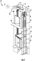
- FIG. 1 shows a schematic view of an elevator system 10, in accordance with an embodiment of the disclosure.
- the elevator system 10 includes an elevator car 23 configured to move vertically upward and downward within a hoistway 50 along a plurality of car guide rails 60.
- the elevator system 10 also includes a counterweight 28 operably connected to the elevator car 23 via a pulley system 26.
- the counterweight 28 is configured to move vertically upward and downward within the hoistway 50.
- the counterweight 28 moves in a direction generally opposite the movement of the elevator car 23, as is known in conventional elevator systems. Movement of the counterweight 28 is guided by counterweight guide rails 70 mounted within the hoistway 50.
- the elevator car 23 also has doors 27 that open and close, allowing passengers to enter and exit the elevator car 23.
- the elevator system 10 also includes a power source 12.
- the power is provided from the power source 12 to a switch panel 14, which may include circuit breakers, meters, etc. From the switch panel 14, the power may be provided directly to the drive unit 20 through a controller 30 or to an internal power source charger 16, which converts AC power to direct current (DC) power to charge an internal power source 18 that requires charging.
- an internal power source 18 that requires charging may be a battery, capacitor, or any other type of power storage device known to one of ordinary skill in the art.
- the internal power source 18 may not require charging from the AC external power source 12 and may be a device such as, for example a gas powered generator, solar cells, hydroelectric generator, wind turbine generator or similar power generation device.
- the internal power source 18 may power various components of the elevator system 10 when an external power source is unavailable.
- the drive unit 20 drives a machine 22 to impart motion to the elevator car 23 via a traction sheave of the machine 22.
- the machine 22 also includes a brake 24 that can be activated to stop the machine 22 and elevator car 23.
- FIG. 1 depicts a machine room-less elevator system 10, however the embodiments disclosed herein may be incorporated with other elevator systems that are not machine room-less or that include any other known elevator configuration.
- elevator systems having more than one independently operating elevator car in each elevator shaft and/or ropeless elevator systems may also be used.
- the elevator car may have two or more compartments.
- the elevator system 10 also includes a sensing system 100 located on the elevator car 23. The sensing system 100 will be discussed further below.
- the controller 30 is responsible for controlling the operation of the elevator system 10.
- the controller 30 may also determine a mode (motoring, regenerative, near balance) of the elevator car 23.
- the controller 30 may use the car direction and the weight distribution between the elevator car 23 and the counterweight 28 to determine the mode of the elevator car.
- the controller 30 may adjust the velocity of the elevator car 23 to reach a target floor.
- the controller 30 may include a processor and an associated memory.
- the processor may be, but is not limited to, a single-processor or multi-processor system of any of a wide array of possible architectures, including field programmable gate array (FPGA), central processing unit (CPU), application specific integrated circuits (ASIC), digital signal processor (DSP) or graphics processing unit (GPU) hardware arranged homogenously or heterogeneously.
- the memory may be but is not limited to a random access memory (RAM), read only memory (ROM), or other electronic, optical, magnetic or any other computer readable medium.
- FIG. 2 shows an illustrated view of a sensing system 100, in accordance with an embodiment of the disclosure.
- the sensing system 100 is in operative communication with the controller 30.
- the sensing system 100 may contain individual controllers that could communicate with the controller 30.
- the sensing system 100 is located on a side of the elevator car 23 opposite a scattering surface 60a.
- the sensing system 100 is located on a side of the elevator car 23 opposite the car guide rail 60 and thus the guide rail 60 is the scattering surface 60a.
- the sensing system 100 may be located in various other locations having various other scattering surfaces 60a, such as, for example on the counterweight 28 opposite the counterweight guide rail 70 (the counterweight guide rail 70 being the scattering surface) and/or on the side of the elevator car 23 opposite a wall of the hoistway 50 (the wall of the hoistway 50 being the scattering surface).
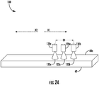
- the sensing system 100 includes a first light source 120a and a first light sensing device 130a.
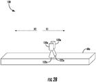
- the first light source 120a and the first light sensing device 130a may be in line with each other as shown in FIG. 2 , perpendicular to each other as shown in FIG. 2A , or any other orientations that may be appreciated by one of skill in the art. In an embodiment, in line may be defined as perpendicular to the direction of motion X1 of the elevator car 23, as shown in FIG. 2.
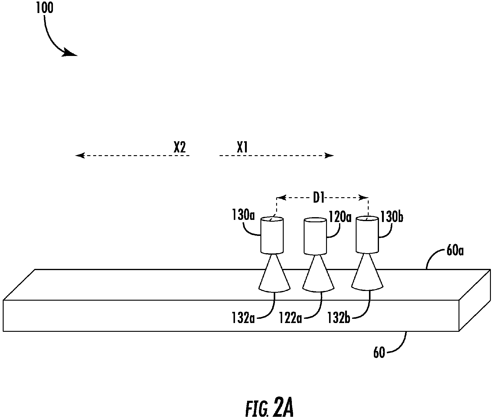
- FIGs. 2 , 2A , and 2B display various configurations for the sensing system 100 that may alter the way the sensing system 100 operates.
- the sensing system 100 may also include a second light source 120b and a second light sensing device 130b.
- the second light source 120b and the second light sensing device 130b may be in line with each other as shown in FIG. 2 .
- the second light sensing device 130b may be located at a first distance D1 away from the first light sensing device 130a towards the first direction X1, thus the second light sensing device 130b will be ahead of the first light sensing device 130a as they travel over the scattering surface 60a.
- the second light sensing device 130b may be located at a first distance D1 away from the first light sensing device 130a away from the first direction X1, thus the second light sensing device 130b will be behind of the first light sensing device 130a as they travel over the scattering surface 60a.
- the size of the first distance D1 may be as small as possible given the geometrical constraints of the light sources and detectors and likely on the order of millimeters.
- first distance D1 may be 10 millimeters. In one embodiment, first distance D1 may be greater than or less than 10 millimeters.
- the second light source 120b is configured to emit a plurality of second light impulses onto the scattering surface 60a at a second impulse rate as the elevator car 23 moves through a route segment in a first direction X1.
- the second light sensing device 130b configured to measure light scattered off the scattering surface 60a for each of the second light impulses and log the measurements as the baseline dataset DS o .
- the first light source 120a is configured to emit a plurality of first light impulses onto a scattering surface 60a at a first impulse rate as the elevator car 23 moves through a route segment in a first direction X1.
- the first light sensing device 130a is configured to measure a first data set DS1 comprising light scattered off the scattering surface 60a for each of the first light impulses.
- a first data set DS1 of scattered light captured by the first light sensing device 130a may be compared to the baseline data set DS o of scattered light captured by the second light sensing device 130b, as seen in FIG. 3 . Then a first correlation is determined between the first data set DS1 and the baseline data set DS o , meaning that the two data sets DS1, DS o should show similar trends in measured scattered light but offset by a first offset time period T1, as shown in FIG. 3 .
- the velocity of the sensing system 100 (and ultimately the elevator car on which the velocity system 100 is located) may be determined in response to the first distance D1 and the first offset time period T1.
- velocity of the sensing system may be determined by dividing the first distance D1 by the first offset time period T1.
- the controller 30 is configured to determine a first correlation in response to the first data set DS1 and the baseline data set DS o .
- the first correlation includes a first offset time period T1 between the first data set DS1 and the baseline dataset DS o .
- the controller 30 is then configured to determine a first velocity in response to the first offset time period T1 and the first distance D1.
- the sensing system 100 may include additional light sources and light sensing devices.
- additional light sources may be able to provide increased accuracy and/or redundancy by being able to compare the determined velocity, as will be discussed further below.
- FIG. 2 shows a third light source 120c and a third light sensing device 130c.
- the third light source 120c and the third light sensing device 130c may be in line with each other as shown in FIG. 2 .
- the third light sensing device 130c may be located at a second distance D2 away from the second light sensing device 130b.
- the second D2 would be optimized for maximum velocity and would likely be on the order of centimeters.
- second distance D2 may be 10 centimeters.
- second distance D2 may be greater than or less than 10 centimeters.
- a second data set DS2 of scattered light captured by the third light sensing device 130c may be compared to the baseline data set DS o of scattered light captured by the second light sensing device 130b, as seen in FIG. 3 . Then a second correlation is determined between the second data set DS2 and the baseline data set DS o , meaning that the two data sets DS2, DS o should show similar trends in measured scattered light but offset by a second offset time period T2, as shown in FIG. 4 .
- the velocity of the sensing system 100 (and ultimately the elevator car on which the velocity system 100 is located) may be determined in response to the second distance D2 and the second offset time period T2.
- velocity of the sensing system may be determined by dividing the first distance D2 by the second offset time period T2.
- the controller 30 is configured to determine a second correlation in response to the second data set DS2 and the baseline data set DS o .
- the second correlation includes a second offset time period T2 between the second data set DS2 and the baseline dataset DS o .
- the controller 30 is then configured to determine a second velocity in response to the second offset time period T2 and the second distance D2.
- the controller 30 is configured to determine a final velocity in response to the first velocity and the second velocity.
- the final velocity may be determined by taking an average of the first velocity and the second velocity.
- the controller 30 may determine the velocity of the elevator car 23 utilizing the distance between any pair of light sources/light sensing devices and the time offset in the data set from those corresponding light sources/light sensing devices.
- the velocity can be determined by comparing the position of the light sensing device 130a-130c on the rail 60 at different times/locations by cross correlating the signal of a light sensing device 130a-130c over a given sample window to that of a learn run, as discussed further below.
- the method of operation associated with the sensor system 100 configuration of FIG. 2 is discussed further below in method 700 and 700a of FIGs. 7 and 7a .
- the sensing system 100 comprises a first light source 120a, a first light sensing device 130a, and a second light sensing device 130b.
- additional light sensing devices may be installed at different locations and at different angles relative to the first light source 130a.
- the second light sensing device 130b is located perpendicular to the first light source 120a towards the first direction X1 and the first light sensing device 130a is located perpendicular to the first light source 120a towards a second direction X2 opposite the first direction X1, as seen in FIG. 2 .
- the first light source 120a is configured to emit a plurality of first light impulses onto the scattering surface 60a at a first impulse rate as the elevator car 23 moves through a route segment in a first direction X1.
- the second light sensing device 130b is configured to measure light scattered off the scattering surface 60a for each of the first light impulses and log the measurements as the baseline dataset DS o .
- the first light sensing device 130a is configured to measure light scattered off the scattering surface 60a for each of the first light impulses as a first data set DS1 and then the first data set DS1 to the baseline dataset DS o .
- the first data set DS1 of scattered light captured by the first light sensing device 130a may be compared to the baseline data set DS o of scattered light captured by the second light sensing device 130b, as seen in FIG. 3 . Then a first correlation is determined between the first data set DS1 and the baseline data set DS o , meaning that the two data sets DS1, DS o should show similar trends in measured scattered light but offset by a first offset time period T1, as shown in FIG. 3 .
- the velocity of the sensing system 100 (and ultimately the elevator car on which the velocity system 100 is located) may be determined in response to the first distance D1 and the first offset time period T1.
- velocity of the sensing system may be determined by dividing the first distance D1 by the first offset time period T1.
- the controller 30 is configured to determine a first correlation in response to the first data set DS1 and the baseline data set DS o .
- the first correlation includes a first offset time period T1 between the first data set DS1 and the baseline dataset DS o .
- the controller 30 is then configured to determine a first velocity in response to the first offset time period T1 and the first distance D1.
- multiple velocity measurements can be used and averaged together to improve accuracy of the measurement and provide additional robustness.
- additional light sensing devices would also enhance sensitivity to surfaces of varying roughness.
- the light sources and the light sensing devices could in principle be swapped. The method of operation associated with the sensor system 100 configuration of FIG. 2A is discussed further below in method 800 of FIG. 8 .
- the sensing system 100 includes a first light source 120a and a first light sensing device 130a.
- the sensor system 100 of FIG. 2B is configured to first conduct a positional learn run prior to moving the elevator car 23 through the route segment. During the learn run, the sensor system 100 is moved over the scattering surface 60a at a selected velocity.
- the first light source 120a is configured to emit a plurality of third light impulses onto the scattering surface 60a at a first impulse rate as the sensor system 100 moves through the learn run in a first direction X1.
- the first light sensing device 130a is configured to measure light scattered off the scattering surface 60a for each of the third light impulses and log the measurements as the baseline data set DS o .
- a relative position on the scattering surface 60a is determined for each of the third light impulses in the baseline data set DS o in response to the selected velocity.
- the first data set DS1 of scattered light captured by the first light sensing device 130a may be compared to the baseline data set DS o captured during the learn run, as seen in FIG. 3 . Then a first correlation is determined between the first data set DS1 and the baseline data set DS o , meaning that the two data sets DS1, DS o should show similar trends in measured scattered light.
- the velocity of the sensing system 100 (and ultimately the elevator car on which the velocity system 100 is located) may be calculated by determining the actual position of the elevator 23 car during the route segment by correlating the first data set DS1 to the baseline data set DS o , for two consecutive measurements. The method of operation associated with the sensor system 100 configuration of FIG. 2B is discussed further below in method 900 of FIG. 9 .
- the light sources 120a-120c may include a light emitting diode (LED) and/or a laser diode.
- the light sources 120a-120c may include other light sources such, as for example an incandescent light bulb, arc lamp, gas discharge lamp, or any other light source known to one of skill in the art.
- the light sources 120a-120c each emit light 122a-122c onto the scattering surface 60a.
- the light sources 120a-120c may each emit light 122a-122c at a selected impulse rate, which would strobe the light 122a-122c on the scattering surface 60a.
- the selected impulse rate may vary between 1 kHz to 100 kHz.
- the selected impulse rate may be less than 1 kHz or greater than 100 kHz.
- the light sources 120a-120c may emit light at one or more wavelengths, such as, for example, infrared light or blue visible light.
- the light sensing devices 130a-130c are configured to measure scattered light signals from their respective light source 120a-120c. Scattered light is light 122a-122c from the light sources 120a-120c that hits the scattering surface 60a and is scattered off in various directions (i.e. scatters).
- light will scatter differently in different areas of the scattering surface 60a.
- the location along the scattering surface 60a may be determined by measuring and logging the light scatter off the scattering surface 60a over a given sensing region and then comparing a current measurement to baseline data.
- the light sensing devices 130a-130c are configured to measure scattered light from their respective light sources 120a-120c reflected off the scattering surface 60a within their respective sensing region 132a-132c.
- the emitted light may completely overlap with the sensing region. In one embodiment, the sensing region 132a-132c may not completely overlap with the respective emitted light 122a-122c.
- the sensing region 132a-132c may not completely overlap with the respective emitted light 122a-122c because light will scatter in various directions and not just where the light is directed by the light source.
- the sensing region 132a-132c may completely overlap with the respective emitted light 122a-122c to detect light scatter.
- the first light sensing device 130a is configured to measure scattered light from the first light source 120a with the first sensing region 132a.
- the light sensing devices 130a-130c may include photodiodes phototransistors, photo resistors, phototubes, and other light sensing sensors known to one of skill in the art.
- the light sources 120a-120c may be oriented at various angles relative to the scattering surface 60a to detect different types of light scatter.
- the first light source 120a and the first light sensing device 130a are oriented in a perpendicular orientation with the scattering surface 60a, which is meant to detect back scatter of light.
- a perpendicular orientation means that a first angle A1 between the scattering surface 60 and a first axis L1 of the first light source 120a is equal to about 90 degrees and a second angle A2 between the scattering surface 60a and a second axis L2 of the first light sensing device 130a is equal to about 90 degrees.
- the perpendicular to the scattering surface 60 the emitted light 122a may overlap with the sensing region 132a.
- the first light source 120a and the first light sensing device 130a are oriented in a non-perpendicular orientation having a first angle of coincidence A3 greater than 90 degrees with the scattering surface 60a, which is meant to capture forward scatter of light.
- a non-perpendicular orientation means that a first angle A1 between the scattering surface 60a and a first axis L1 of the first light source 120a is not equal to 90 degrees and a second angle A2 between the scattering surface 60 and a second axis L2 of the first light sensing device 130a is not equal to 90 degrees.
- a non-perpendicular orientation also means that a first angle of coincidence A3 between the first light source 120a and the first light sensing device 130a is not equal to zero.
- the first angle of coincidence A3 In a perpendicular orientation, the first angle of coincidence A3 would be about zero.
- the first angle of coincidence A3 may be defined as the angle between the first axis L1 and the second axis L2.
- a first angle of coincidence A3 of 180 degrees would mean that the first light source 120a is pointing directly at the first light sensing device 130a.
- Each set of light sources and light sensing devices have their own angle of coincidences.
- a first angle of coincidence A3 between the first light source 120a and the first light sensing device 130a is greater than 0 degrees and less than or equal to about 180 degrees; and a second angle of coincidence between the second light source 120b and the second light sensing device 130b is about equal to the first angle of coincidence A3.
- the second and third light sources 120b, 120c are orientated at the same angle A1 with respect to the scattering surface 60a as the first light source 120a.
- the second and third light sensing devices 130b, 130c are orientated at the same angle A2 with respect to the scattering surface 60a as the first light sensing device 130a.
- the second light source 120b and the second light sensing device 130b have the same angle of coincidences as the first light source 120a and the first light sensing device 130a.
- the third light source 120c and the third light sensing device 130c have the same angle of coincidences as the first light source 120a and the first light sensing device 130a.
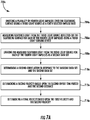
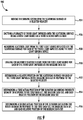
- FIG. 6 shows a flow chart of method 600 of monitoring an elevator car 23, in accordance with an embodiment of the disclosure.
- the elevator car 23 through a route segment in a first direction X1.
- the sensing system 100 integrally connected to the elevator car 23 is moved over a segment of a scattering surface.
- the sensing system 100 comprises a first light source 120a and a first light sensing device 130a.
- a plurality of first light impulses are emitted onto the scattering surface 60a using the first light source 120a at a first impulse rate.
- a first data set DS1 is measured.
- the first set of data DS1 comprises light scattered off the scattering surface 60a for each of the first light impulses using the first light sensing device 120a.
- a first velocity of the elevator car 23 is determined in response to the first data set DS1 and a baseline data set DS o .
- the method of collection of the baseline data set DS o will vary based on the configured of the sensor system 100, as illustrated in FIGs. 6, 6A, and 6B .
- FIG. 7 shows the method 700 of collection of the baseline data set DS o using the sensor system 100 configuration of FIG. 2 .
- the baseline data set DS o is determined while the elevator 23 is moved through the route segment.
- a plurality of second light impulses are emitted onto the scattering surface 60a using a second light source 120b at a second selected impulse rate.
- scattered light from the second light source 120b reflected off the scattering surface 60a is measured for each of the second light impulses using a second light sensing device 130b.
- the second light detecting device 130b is located at a first distance D1 away from the first light detecting device towards the first direction X1.
- the measured scattered light from the second light source 120b for each of the second light impulses is logged as a baseline data set DS o .
- the baseline data set DS o may be logged in the memory of the controller 30 or in the sensor system 100.
- a first correlation is determined in response to the first data set DS1 and the baseline data set DS o .
- the first correlation includes a first offset time period T1 between the first data set DS1 and baseline data set DS o .
- the first velocity from block 612 of the elevator car 23 is determined based upon the first offset time period T1 and the first distance D 1.
- the additional steps of method 700a in FIG. 7A may be added onto method 700.
- a plurality of fourth light impulses are emitted onto the scattering surface 60a using a third light source 120c at a fourth selected impulse rate.
- scattered light from the third light source 120c is reflected off the scattering surface 60a is measured for each of the fourth light impulses using a third light sensing device 130c.
- the third light detecting device 130c is located at a first distance D2 away from the first light detecting device 120a towards the second direction X2.
- the measured scattered light from the third light source 120b for each of the second light impulses is logged as a second data set DS2.
- the second dataset DS1 may be compared to the baseline data set DS o .
- a second correlation is determined in response to the second data set DS2 and the baseline data set DS o .
- the first correlation includes a second offset time period T2 between the second data set DS2 and baseline data set DS o .
- a second velocity based upon the second offset time period T2 and the second distance D2 is determined.
- a final velocity is determined based upon the first velocity determined in block 612 and the second velocity determined in block 710a.
- FIG. 8 shows the method 800 of collection of the baseline data set DS o using the sensor system 100 configuration of FIG. 2A .
- the baseline data set DS o is determined while the elevator 23 is moved through the route segment.
- scattered light from the first light source 120a reflected off the scattering surface 60a is measured for each of the first light impulses using a second light sensing device 130a.
- the second light sensing device 130b is located perpendicular to the first light source 120a towards the first direction X1 and the first light sensing device 130a is located perpendicular to the first light source 120a towards a second direction X2 opposite the first direction X1.
- the measured scattered light from the second light source 120b is logged for each of the first light impulses as a baseline data set DS o .
- the baseline data set DS o may be logged in the memory of the controller 30 or in the sensor system 100.
- a first correlation in response to the first data set DS1 and the baseline data set DS o .
- the first correlation includes a first offset time period T1 between the first data set DS1 and baseline data set DS o .
- the first velocity from block 612 of the elevator car 23 is determined based upon the first offset time period T1 and the first distance D1.
- FIG. 9 shows the method 900 of collection of the baseline data set DS o using the sensor system 100 configuration of FIG. 2B .
- the baseline data set DS o is determined through a positional learn run conducted prior to the elevator 23 moving through the route segment.
- the sensing system 100 of FIG. 2B is moved over the scattering surface 60a at a selected velocity.
- a plurality of third light impulses is emitted onto the scattering surface 60a using a first light source 120a at a third selected impulse rate.
- the scattered light from the first light source 120a reflected off the scattering surface 60a is measured for each of the third light impulses using the first light sensing device 130a.
- the measured scattered light from the first light source 120a for each of the third light impulses is logged as the baseline data set DS o .
- the baseline data set DS o may be logged in the memory of the controller 30 or in the sensor system 100.
- a first actual position of the elevator car 23a during the route segment is determined in response to the first data set DS1, the baseline data set DS o , and each relative position of the baseline data set DS o .
- a second actual position of the elevator car 23a during the route segment is determined in response to the first data set DS1, the baseline data set DS o , and each relative position of the baseline data set DS o .
- the first velocity from block 612 is determined in response to the first actual position, the second actual position, and an elapsed time between the first actual position and the second actual position.
- embodiments can be in the form of processor-implemented processes and devices for practicing those processes, such as processor.
- Embodiments can also be in the form of computer program code containing instructions embodied in tangible media, such as network cloud storage, SD cards, flash drives, floppy diskettes, CD ROMs, hard drives, or any other computer-readable storage medium, wherein, when the computer program code is loaded into and executed by a computer, the computer becomes a device for practicing the embodiments.
- Embodiments can also be in the form of computer program code, for example, whether stored in a storage medium, loaded into and/or executed by a computer, or transmitted over some transmission medium, loaded into and/or executed by a computer, or transmitted over some transmission medium, such as over electrical wiring or cabling, through fiber optics, or via electromagnetic radiation, wherein, when the computer program code is loaded into an executed by a computer, the computer becomes an device for practicing the embodiments.
- the computer program code segments configure the microprocessor to create specific logic circuits.
Landscapes
- Engineering & Computer Science (AREA)
- Automation & Control Theory (AREA)
- Computer Networks & Wireless Communication (AREA)
- Physics & Mathematics (AREA)
- General Physics & Mathematics (AREA)
- Electromagnetism (AREA)
- Power Engineering (AREA)
- Indicating And Signalling Devices For Elevators (AREA)
- Length Measuring Devices By Optical Means (AREA)
Abstract
A method of monitoring an elevator car is provided. The method comprising: moving the elevator car (27) through a route segment in a first direction; moving a sensing system (100) integrally connected to the elevator car (27) over a segment of a scattering surface, the sensing system (100) comprising a first light source and a first light sensing device; emitting a plurality of first light impulses onto the scattering surface using the first light source at a first impulse rate; measuring a first data set comprising light scattered off the scattering surface for each of the first light impulses using the first light sensing device; and determining a first velocity of the elevator car in response to the first data set and a baseline data set.

Description
- The subject matter disclosed herein relates generally to the field velocity monitoring, and specifically to a method and apparatus for monitoring the velocity (and position) of an elevator car.
- Commonly, the velocity of an elevator car is determined indirectly by monitoring the cable drive system and/or directly by installing additional encoding tape that can be read via a sensor on the elevator car. An efficient method of directly monitoring the velocity of the elevator car without the need to install encoding tape is desired.
- According to one embodiment, a method of monitoring an elevator car is provided. The method comprising: moving the elevator car through a route segment in a first direction; moving a sensing system integrally connected to the elevator car over a segment of a scattering surface, the sensing system comprising a first light source and a first light sensing device; emitting a plurality of first light impulses onto the scattering surface using the first light source at a first impulse rate; measuring a first data set comprising light scattered off the scattering surface for each of the first light impulses using the first light sensing device; and determining a first velocity of the elevator car in response to the first data set and a baseline data set.
- In addition to one or more of the features described above, or as an alternative, further embodiments of the method may include determining the baseline data through a baseline run conducted while moving the elevator through the route segment, the baseline run comprising: emitting a plurality of second light impulses onto the scattering surface using a second light source at a second selected impulse rate; measuring scattered light from the second light source reflected off the scattering surface for each of the second light impulses using a second light sensing device, the second light detecting device being located at a first distance away from the first light detecting device towards the first direction; and logging the measured scattered light from the second light source for each of the second light impulses as a baseline data set.
- In addition to one or more of the features described above, or as an alternative, further embodiments of the method may include determining a first correlation in response to the first data set and the baseline data set, the first correlation includes a first offset time period between the first data set and baseline data set; wherein the first velocity of the elevator car is determined based upon the first offset time period and the first distance.
- In addition to one or more of the features described above, or as an alternative, further embodiments of the method may include determining the baseline data through a baseline run conducted while moving the elevator through the route segment, the baseline run comprising: measuring scattered light from the first light source reflected off the scattering surface for each of the first light impulses using a second light sensing device, wherein the second light sensing device is located perpendicular to the first light source towards the first direction and the first light sensing device is located perpendicular to the first light source towards a second direction opposite the first direction; and logging the measured scattered light from the second light source for each of the first light impulses as a baseline data set.
- In addition to one or more of the features described above, or as an alternative, further embodiments of the method may include determining a first correlation in response to the first data set and the baseline data set, the first correlation includes a first offset time period between the first data set and baseline data set; wherein the first velocity of the elevator car is determined based upon the first offset time period and the first distance.
- In addition to one or more of the features described above, or as an alternative, further embodiments of the method may include determining the baseline data through a positional learn run conducted prior to moving the elevator through the route segment, the positional learn run comprising: moving the sensing system over the scattering surface at a selected velocity; emitting a plurality of third light impulses onto the scattering surface using a first light source at a third selected impulse rate; measuring scattered light from the first light source reflected off the scattering surface for each of the third light impulses using the first light sensing device; logging the measured scattered light from the first light source for each of the third light impulses as the baseline data set; and determining a relative position on the scattering surface for each of the third light impulses in the baseline data set in response to the selected velocity.
- In addition to one or more of the features described above, or as an alternative, further embodiments of the method may include determining a first actual position of the elevator car during the route segment in response to the first data set, the baseline data set, and each relative position of the baseline data set; and determining a second actual position of the elevator car during the route segment in response to the first data set, the baseline data set, and each relative position of the baseline data set; wherein the first velocity is determined in response to the first actual position, the second actual position, and an elapsed time between the first actual position and the second actual position.
- In addition to one or more of the features described above, or as an alternative, further embodiments of the method may include: emitting a plurality of fourth light impulses onto the scattering surface using a third light source at a fourth selected impulse rate, the third light source being located at a second distance away from the second light source towards a second direction opposite the first direction; measuring scattered light from the third light source reflected off the scattering surface for each of the fourth light impulses using a third light sensing device; logging the measured scattered light from the third light source for each of the fourth light impulses as a second data set; determining a second correlation in response to the baseline data set and the second data set, the second correlation includes a second offset time period between the baseline data set and the second data set; determining a second velocity based upon the second offset time period and the second distance; and determining a final velocity based upon the first velocity and the second velocity.
- In addition to one or more of the features described above, or as an alternative, further embodiments of the method may include that the scattering surface is an elevator car guide rail.
- According to another embodiment, a sensing system for monitoring an elevator car is provided. The sensor system comprising: a first light source configured to emit a plurality of first light impulses onto a scattering surface at a first impulse rate as the elevator car moves through a route segment in a first direction; a first light sensing device configured to measure a first data set comprising light scattered off the scattering surface for each of the first light impulses; and a controller configured to determine a first velocity of the elevator car in response to the first data set and a baseline data set.
- In addition to one or more of the features described above, or as an alternative, further embodiments of the sensing system may include: a second light source configured to emit a plurality of second light impulses onto the scattering surface at a second impulse rate as the elevator car moves through a route segment in a first direction; and a second light sensing device configured to measure light scattered off the scattering surface for each of the second light impulses and log the measurements as the baseline dataset, the second light sensing device being located at a first distance away from the first light sensing device towards the first direction.
- In addition to one or more of the features described above, or as an alternative, further embodiments of the sensing system may include that the controller is configured to determine a first correlation in response to the first data set and the baseline data set, the first correlation includes a first offset time period between the first data set and baseline data set; wherein the first velocity of the elevator car is determined based upon the first offset time period and the first distance.
- In addition to one or more of the features described above, or as an alternative, further embodiments of the sensing system may include a second light sensing device configured to measure light scattered off the scattering surface for each of the first light impulses and log the measurements as the baseline dataset, the second light sensing device being located perpendicular to the first light source towards the first direction and the first light sensing device is located perpendicular to the first light source towards a second direction opposite the first direction; wherein the second light sensing device is located at a first distance away from the first light sensing device.
- In addition to one or more of the features described above, or as an alternative, further embodiments of the sensing system may include that the controller is configured to determine a first correlation in response to the first data set and the baseline data set, the first correlation includes a first offset time period between the first data set and baseline data set; wherein the first velocity of the elevator car is determined based upon the first offset time period and the first distance.
- In addition to one or more of the features described above, or as an alternative, further embodiments of the sensing system may include that the baseline data is determined through a positional learn run conducted prior to moving the elevator through the route segment, the positional learn run having operations comprising: moving the sensing system over the scattering surface at a selected velocity; emitting a plurality of third light impulses onto the scattering surface using a first light source at a third selected impulse rate; measuring scattered light from the first light source reflected off the scattering surface for each of the third light impulses using the first light sensing device; logging the measured scattered light from the first light source for each of the third light impulses as the baseline data set; and determining a relative position on the scattering surface for each of the third light impulses in the baseline data set in response to the selected velocity.
- In addition to one or more of the features described above, or as an alternative, further embodiments of the sensing system may include that the controller is configured to determine: a first actual position of the elevator car during the route segment in response to the first data set, the baseline data set, and each relative position of the baseline data set; and a second actual position of the elevator car during the route segment in response to the first data set, the baseline data set, and each relative position of the baseline data set; wherein the first velocity is determined in response to the first actual position, the second actual position, and an elapsed time between the first actual position and the second actual position.
- In addition to one or more of the features described above, or as an alternative, further embodiments of the sensing system may include that the scattering surface is an elevator car guide rail.
- In addition to one or more of the features described above, or as an alternative, further embodiments of the sensing system may include that the first light source and the first light sensing device are located on the elevator car.
- In addition to one or more of the features described above, or as an alternative, further embodiments of the sensing system may include that the first light source, the first light sensing device, the second light source, and the second light sensing device are each oriented in a perpendicular orientation with the scattering surface.
- In addition to one or more of the features described above, or as an alternative, further embodiments of the sensing system may include that a first angle of coincidence between the first light source and the first light sensing device is greater than 0 degrees and less than or equal to about 180 degrees; and a second angle of coincidence between the second light source and the second light sensing device is about equal to the first angle of coincidence.
- Technical effects of embodiments of the present disclosure include the ability to determine the velocity of an elevator car through measuring, logging and comparing the light scatter off of a scattering surface as the elevator car moves through an elevator shaft.
- The foregoing features and elements may be combined in various combinations without exclusivity, unless expressly indicated otherwise. These features and elements as well as the operation thereof will become more apparent in light of the following description and the accompanying drawings. It should be understood, however, that the following description and drawings are intended to be illustrative and explanatory in nature and non-limiting.
- The foregoing and other features, and advantages of the disclosure are apparent from the following detailed description taken in conjunction with the accompanying drawings in which like elements are numbered alike in the several FIGURES:
-
FIG. 1 illustrates a schematic view of an elevator system, in accordance with an embodiment of the disclosure; -
FIG. 2 illustrates a schematic view of a configuration of a sensing system that may be incorporated on the elevator systems ofFIG. 1 , in accordance with an embodiment of the disclosure; -
FIG. 2A illustrates a schematic view of an alternate configuration of a sensing system that may be incorporated on the elevator systems ofFIG. 1 , in accordance with an embodiment of the disclosure; -
FIG. 2B illustrates a schematic view of an alternate configuration of a sensing system that may be incorporated on the elevator systems ofFIG. 1 , in accordance with an embodiment of the disclosure; -
FIG. 3 illustrates a schematic view of the data output from the sensing system ofFIG. 2 , in accordance with an embodiment of the disclosure; -
FIG. 4 illustrates a schematic view of the relative orientation of a light source, a light sensing device, and a scattering surface within the sensing system, in accordance with an embodiment of the disclosure; -
FIG. 5 illustrates a schematic view of the relative orientation of a light source, a light sensing device, and a scattering surface within the sensing system, in accordance with an embodiment of the disclosure; -
FIG. 6 is a flow chart of a method of monitoring an elevator car, in accordance with an embodiment of the disclosure; -
FIG. 7 is a flow chart of additional steps in the method ofFIG. 6 for monitoring an elevator car, in accordance with an embodiment of the disclosure; -
FIG. 7A is a flow chart of additional steps in the method ofFIG. 7 for monitoring an elevator car, in accordance with an embodiment of the disclosure; -
FIG. 8 is a flow chart of additional steps in the method ofFIG. 6 for monitoring an elevator car, in accordance with an embodiment of the disclosure; and -
FIG. 9 is a flow chart of additional steps in the method ofFIG. 8 for monitoring an elevator car, in accordance with an embodiment of the disclosure. -
FIG. 1 shows a schematic view of anelevator system 10, in accordance with an embodiment of the disclosure. With reference toFIG. 1 , theelevator system 10 includes anelevator car 23 configured to move vertically upward and downward within ahoistway 50 along a plurality ofcar guide rails 60. Theelevator system 10 also includes acounterweight 28 operably connected to theelevator car 23 via apulley system 26. Thecounterweight 28 is configured to move vertically upward and downward within thehoistway 50. Thecounterweight 28 moves in a direction generally opposite the movement of theelevator car 23, as is known in conventional elevator systems. Movement of thecounterweight 28 is guided bycounterweight guide rails 70 mounted within thehoistway 50. Theelevator car 23 also hasdoors 27 that open and close, allowing passengers to enter and exit theelevator car 23. - The
elevator system 10 also includes apower source 12. The power is provided from thepower source 12 to aswitch panel 14, which may include circuit breakers, meters, etc. From theswitch panel 14, the power may be provided directly to thedrive unit 20 through acontroller 30 or to an internalpower source charger 16, which converts AC power to direct current (DC) power to charge aninternal power source 18 that requires charging. For instance, aninternal power source 18 that requires charging may be a battery, capacitor, or any other type of power storage device known to one of ordinary skill in the art. Alternatively, theinternal power source 18 may not require charging from the ACexternal power source 12 and may be a device such as, for example a gas powered generator, solar cells, hydroelectric generator, wind turbine generator or similar power generation device. Theinternal power source 18 may power various components of theelevator system 10 when an external power source is unavailable. Thedrive unit 20 drives amachine 22 to impart motion to theelevator car 23 via a traction sheave of themachine 22. Themachine 22 also includes abrake 24 that can be activated to stop themachine 22 andelevator car 23. As will be appreciated by those of skill in the art,FIG. 1 depicts a machineroom-less elevator system 10, however the embodiments disclosed herein may be incorporated with other elevator systems that are not machine room-less or that include any other known elevator configuration. In addition, elevator systems having more than one independently operating elevator car in each elevator shaft and/or ropeless elevator systems may also be used. In one embodiment, the elevator car may have two or more compartments. Theelevator system 10 also includes asensing system 100 located on theelevator car 23. Thesensing system 100 will be discussed further below. - The
controller 30 is responsible for controlling the operation of theelevator system 10. Thecontroller 30 may also determine a mode (motoring, regenerative, near balance) of theelevator car 23. Thecontroller 30 may use the car direction and the weight distribution between theelevator car 23 and thecounterweight 28 to determine the mode of the elevator car. Thecontroller 30 may adjust the velocity of theelevator car 23 to reach a target floor. Thecontroller 30 may include a processor and an associated memory. The processor may be, but is not limited to, a single-processor or multi-processor system of any of a wide array of possible architectures, including field programmable gate array (FPGA), central processing unit (CPU), application specific integrated circuits (ASIC), digital signal processor (DSP) or graphics processing unit (GPU) hardware arranged homogenously or heterogeneously. The memory may be but is not limited to a random access memory (RAM), read only memory (ROM), or other electronic, optical, magnetic or any other computer readable medium. - Referring now to
FIGs. 2-5 ,FIG. 2 shows an illustrated view of asensing system 100, in accordance with an embodiment of the disclosure. Thesensing system 100 is in operative communication with thecontroller 30. Alternatively, thesensing system 100 may contain individual controllers that could communicate with thecontroller 30. As shown inFIGs. 1 and2 , thesensing system 100 is located on a side of theelevator car 23 opposite ascattering surface 60a. In the illustrated embodiment ofFIG. 2 , thesensing system 100 is located on a side of theelevator car 23 opposite thecar guide rail 60 and thus theguide rail 60 is thescattering surface 60a. As may be appreciated by one of skill in the art, thesensing system 100 may be located in various other locations having variousother scattering surfaces 60a, such as, for example on thecounterweight 28 opposite the counterweight guide rail 70 (thecounterweight guide rail 70 being the scattering surface) and/or on the side of theelevator car 23 opposite a wall of the hoistway 50 (the wall of thehoistway 50 being the scattering surface). - As shown in
FIG. 2 , thesensing system 100 includes afirst light source 120a and a firstlight sensing device 130a. Thefirst light source 120a and the firstlight sensing device 130a may be in line with each other as shown inFIG. 2 , perpendicular to each other as shown inFIG. 2A , or any other orientations that may be appreciated by one of skill in the art. In an embodiment, in line may be defined as perpendicular to the direction of motion X1 of theelevator car 23, as shown inFIG. 2. FIGs. 2 ,2A , and2B display various configurations for thesensing system 100 that may alter the way thesensing system 100 operates. - As shown in
FIG. 2 , thesensing system 100 may also include a secondlight source 120b and a secondlight sensing device 130b. The secondlight source 120b and the secondlight sensing device 130b may be in line with each other as shown inFIG. 2 . In the embodiment ofFIG. 2 , the secondlight sensing device 130b may be located at a first distance D1 away from the firstlight sensing device 130a towards the first direction X1, thus the secondlight sensing device 130b will be ahead of the firstlight sensing device 130a as they travel over thescattering surface 60a. In an alternate embodiment, the secondlight sensing device 130b may be located at a first distance D1 away from the firstlight sensing device 130a away from the first direction X1, thus the secondlight sensing device 130b will be behind of the firstlight sensing device 130a as they travel over thescattering surface 60a. Advantageously, the size of the first distance D1 may be as small as possible given the geometrical constraints of the light sources and detectors and likely on the order of millimeters. In one embodiment, first distance D1 may be 10 millimeters. In one embodiment, first distance D1 may be greater than or less than 10 millimeters. - In the configuration shown in
FIG. 2 , the secondlight source 120b is configured to emit a plurality of second light impulses onto thescattering surface 60a at a second impulse rate as theelevator car 23 moves through a route segment in a first direction X1. The secondlight sensing device 130b configured to measure light scattered off thescattering surface 60a for each of the second light impulses and log the measurements as the baseline dataset DSo. Meanwhile, thefirst light source 120a is configured to emit a plurality of first light impulses onto ascattering surface 60a at a first impulse rate as theelevator car 23 moves through a route segment in a first direction X1. The firstlight sensing device 130a is configured to measure a first data set DS1 comprising light scattered off thescattering surface 60a for each of the first light impulses. - As
sensing system 100 moves in a first direction X1, a first data set DS1 of scattered light captured by the firstlight sensing device 130a may be compared to the baseline data set DSo of scattered light captured by the secondlight sensing device 130b, as seen inFIG. 3 . Then a first correlation is determined between the first data set DS1 and the baseline data set DSo, meaning that the two data sets DS1, DSo should show similar trends in measured scattered light but offset by a first offset time period T1, as shown inFIG. 3 . The velocity of the sensing system 100 (and ultimately the elevator car on which thevelocity system 100 is located) may be determined in response to the first distance D1 and the first offset time period T1. Specifically, velocity of the sensing system may be determined by dividing the first distance D1 by the first offset time period T1. In an embodiment, thecontroller 30 is configured to determine a first correlation in response to the first data set DS1 and the baseline data set DSo. The first correlation includes a first offset time period T1 between the first data set DS1 and the baseline dataset DSo. Thecontroller 30 is then configured to determine a first velocity in response to the first offset time period T1 and the first distance D1. - The
sensing system 100 may include additional light sources and light sensing devices. Advantageously, additional light sources may be able to provide increased accuracy and/or redundancy by being able to compare the determined velocity, as will be discussed further below. For instance,FIG. 2 shows a thirdlight source 120c and a thirdlight sensing device 130c. The thirdlight source 120c and the thirdlight sensing device 130c may be in line with each other as shown inFIG. 2 . The thirdlight sensing device 130c may be located at a second distance D2 away from the secondlight sensing device 130b. Advantageously, the second D2 would be optimized for maximum velocity and would likely be on the order of centimeters. In one embodiment, second distance D2 may be 10 centimeters. In one embodiment, second distance D2 may be greater than or less than 10 centimeters. - As
sensing system 100 moves in a first direction X1, a second data set DS2 of scattered light captured by the thirdlight sensing device 130c may be compared to the baseline data set DSo of scattered light captured by the secondlight sensing device 130b, as seen inFIG. 3 . Then a second correlation is determined between the second data set DS2 and the baseline data set DSo, meaning that the two data sets DS2, DSo should show similar trends in measured scattered light but offset by a second offset time period T2, as shown inFIG. 4 . The velocity of the sensing system 100 (and ultimately the elevator car on which thevelocity system 100 is located) may be determined in response to the second distance D2 and the second offset time period T2. Specifically, velocity of the sensing system may be determined by dividing the first distance D2 by the second offset time period T2. In an embodiment, thecontroller 30 is configured to determine a second correlation in response to the second data set DS2 and the baseline data set DSo. The second correlation includes a second offset time period T2 between the second data set DS2 and the baseline dataset DSo. Thecontroller 30 is then configured to determine a second velocity in response to the second offset time period T2 and the second distance D2. - The
controller 30 is configured to determine a final velocity in response to the first velocity and the second velocity. In one embodiment, the final velocity may be determined by taking an average of the first velocity and the second velocity. In one embodiment, thecontroller 30 may determine the velocity of theelevator car 23 utilizing the distance between any pair of light sources/light sensing devices and the time offset in the data set from those corresponding light sources/light sensing devices. In another embodiment, the velocity can be determined by comparing the position of thelight sensing device 130a-130c on therail 60 at different times/locations by cross correlating the signal of alight sensing device 130a-130c over a given sample window to that of a learn run, as discussed further below. The method of operation associated with thesensor system 100 configuration ofFIG. 2 is discussed further below inmethod FIGs. 7 and7a . - In the configuration shown in
FIG. 2A , thesensing system 100 comprises afirst light source 120a, a firstlight sensing device 130a, and a secondlight sensing device 130b. In alternate embodiments, additional light sensing devices may be installed at different locations and at different angles relative to thefirst light source 130a. The secondlight sensing device 130b is located perpendicular to thefirst light source 120a towards the first direction X1 and the firstlight sensing device 130a is located perpendicular to thefirst light source 120a towards a second direction X2 opposite the first direction X1, as seen inFIG. 2 . - The
first light source 120a is configured to emit a plurality of first light impulses onto thescattering surface 60a at a first impulse rate as theelevator car 23 moves through a route segment in a first direction X1. The secondlight sensing device 130b is configured to measure light scattered off thescattering surface 60a for each of the first light impulses and log the measurements as the baseline dataset DSo. Then the firstlight sensing device 130a is configured to measure light scattered off thescattering surface 60a for each of the first light impulses as a first data set DS1 and then the first data set DS1 to the baseline dataset DSo. - As
sensing system 100 moves in a first direction X1, the first data set DS1 of scattered light captured by the firstlight sensing device 130a may be compared to the baseline data set DSo of scattered light captured by the secondlight sensing device 130b, as seen inFIG. 3 . Then a first correlation is determined between the first data set DS1 and the baseline data set DSo, meaning that the two data sets DS1, DSo should show similar trends in measured scattered light but offset by a first offset time period T1, as shown inFIG. 3 . The velocity of the sensing system 100 (and ultimately the elevator car on which thevelocity system 100 is located) may be determined in response to the first distance D1 and the first offset time period T1. Specifically, velocity of the sensing system may be determined by dividing the first distance D1 by the first offset time period T1. In an embodiment, thecontroller 30 is configured to determine a first correlation in response to the first data set DS1 and the baseline data set DSo. The first correlation includes a first offset time period T1 between the first data set DS1 and the baseline dataset DSo. Thecontroller 30 is then configured to determine a first velocity in response to the first offset time period T1 and the first distance D1. In alternate embodiments with additional light sensing devices, multiple velocity measurements can be used and averaged together to improve accuracy of the measurement and provide additional robustness. Advantageously, additional light sensing devices would also enhance sensitivity to surfaces of varying roughness. Additionally, the light sources and the light sensing devices could in principle be swapped. The method of operation associated with thesensor system 100 configuration ofFIG. 2A is discussed further below inmethod 800 ofFIG. 8 . - In the configuration shown in
FIG. 2B , thesensing system 100 includes afirst light source 120a and a firstlight sensing device 130a. Thesensor system 100 ofFIG. 2B is configured to first conduct a positional learn run prior to moving theelevator car 23 through the route segment. During the learn run, thesensor system 100 is moved over thescattering surface 60a at a selected velocity. Thefirst light source 120a is configured to emit a plurality of third light impulses onto thescattering surface 60a at a first impulse rate as thesensor system 100 moves through the learn run in a first direction X1. The firstlight sensing device 130a is configured to measure light scattered off thescattering surface 60a for each of the third light impulses and log the measurements as the baseline data set DSo. A relative position on thescattering surface 60a is determined for each of the third light impulses in the baseline data set DSo in response to the selected velocity. Once the learn run is complete, theelevator car 23 may be moved through the route segment in the first direction X1. - As
sensing system 100 moves in a first direction X1, the first data set DS1 of scattered light captured by the firstlight sensing device 130a may be compared to the baseline data set DSo captured during the learn run, as seen inFIG. 3 . Then a first correlation is determined between the first data set DS1 and the baseline data set DSo, meaning that the two data sets DS1, DSo should show similar trends in measured scattered light. The velocity of the sensing system 100 (and ultimately the elevator car on which thevelocity system 100 is located) may be calculated by determining the actual position of theelevator 23 car during the route segment by correlating the first data set DS1 to the baseline data set DSo, for two consecutive measurements. The method of operation associated with thesensor system 100 configuration ofFIG. 2B is discussed further below inmethod 900 ofFIG. 9 . - In an embodiment, the
light sources 120a-120c may include a light emitting diode (LED) and/or a laser diode. Thelight sources 120a-120c may include other light sources such, as for example an incandescent light bulb, arc lamp, gas discharge lamp, or any other light source known to one of skill in the art. Thelight sources 120a-120c each emit light 122a-122c onto thescattering surface 60a. Thelight sources 120a-120c may each emit light 122a-122c at a selected impulse rate, which would strobe the light 122a-122c on thescattering surface 60a. For example, the selected impulse rate may vary between 1 kHz to 100 kHz. In one embodiment, the selected impulse rate may be less than 1 kHz or greater than 100 kHz. Thelight sources 120a-120c may emit light at one or more wavelengths, such as, for example, infrared light or blue visible light. Thelight sensing devices 130a-130c are configured to measure scattered light signals from their respectivelight source 120a-120c. Scattered light is light 122a-122c from thelight sources 120a-120c that hits thescattering surface 60a and is scattered off in various directions (i.e. scatters). Advantageously, light will scatter differently in different areas of thescattering surface 60a. The location along thescattering surface 60a may be determined by measuring and logging the light scatter off thescattering surface 60a over a given sensing region and then comparing a current measurement to baseline data. Thelight sensing devices 130a-130c are configured to measure scattered light from theirrespective light sources 120a-120c reflected off thescattering surface 60a within theirrespective sensing region 132a-132c. As may be appreciated by one of skill in the art, the emitted light may completely overlap with the sensing region. In one embodiment, thesensing region 132a-132c may not completely overlap with the respective emitted light 122a-122c. For example, on a rough surface, thesensing region 132a-132c may not completely overlap with the respective emitted light 122a-122c because light will scatter in various directions and not just where the light is directed by the light source. In another example, on a smooth highly reflective scattering surface, thesensing region 132a-132c may completely overlap with the respective emitted light 122a-122c to detect light scatter. For example, the firstlight sensing device 130a is configured to measure scattered light from thefirst light source 120a with thefirst sensing region 132a. Thelight sensing devices 130a-130c may include photodiodes phototransistors, photo resistors, phototubes, and other light sensing sensors known to one of skill in the art. - The
light sources 120a-120c may be oriented at various angles relative to thescattering surface 60a to detect different types of light scatter. In the example ofFIG. 4 , thefirst light source 120a and the firstlight sensing device 130a are oriented in a perpendicular orientation with thescattering surface 60a, which is meant to detect back scatter of light. A perpendicular orientation means that a first angle A1 between the scatteringsurface 60 and a first axis L1 of thefirst light source 120a is equal to about 90 degrees and a second angle A2 between the scatteringsurface 60a and a second axis L2 of the firstlight sensing device 130a is equal to about 90 degrees. As may be appreciated by one of skill in the art, although the perpendicular to thescattering surface 60, the emitted light 122a may overlap with thesensing region 132a. - In the example of
FIG. 5 , thefirst light source 120a and the firstlight sensing device 130a are oriented in a non-perpendicular orientation having a first angle of coincidence A3 greater than 90 degrees with thescattering surface 60a, which is meant to capture forward scatter of light. A non-perpendicular orientation means that a first angle A1 between the scatteringsurface 60a and a first axis L1 of thefirst light source 120a is not equal to 90 degrees and a second angle A2 between the scatteringsurface 60 and a second axis L2 of the firstlight sensing device 130a is not equal to 90 degrees. A non-perpendicular orientation also means that a first angle of coincidence A3 between thefirst light source 120a and the firstlight sensing device 130a is not equal to zero. In a perpendicular orientation, the first angle of coincidence A3 would be about zero. The first angle of coincidence A3 may be defined as the angle between the first axis L1 and the second axis L2. A first angle of coincidence A3 of 180 degrees would mean that thefirst light source 120a is pointing directly at the firstlight sensing device 130a. Each set of light sources and light sensing devices have their own angle of coincidences. In an embodiment, a first angle of coincidence A3 between thefirst light source 120a and the firstlight sensing device 130a is greater than 0 degrees and less than or equal to about 180 degrees; and a second angle of coincidence between the secondlight source 120b and the secondlight sensing device 130b is about equal to the first angle of coincidence A3. - In an embodiment, the second and third
light sources scattering surface 60a as thefirst light source 120a. In another embodiment, the second and thirdlight sensing devices scattering surface 60a as the firstlight sensing device 130a. In another embodiment, the secondlight source 120b and the secondlight sensing device 130b have the same angle of coincidences as thefirst light source 120a and the firstlight sensing device 130a. In another embodiment, the thirdlight source 120c and the thirdlight sensing device 130c have the same angle of coincidences as thefirst light source 120a and the firstlight sensing device 130a. - Referring now to
FIGs. 6-9 , while referencing components ofFIGs. 1-5 .FIG. 6 shows a flow chart ofmethod 600 of monitoring anelevator car 23, in accordance with an embodiment of the disclosure. Atblock 604, theelevator car 23 through a route segment in a first direction X1. Atblock 606, thesensing system 100 integrally connected to theelevator car 23 is moved over a segment of a scattering surface. As mentioned above, thesensing system 100 comprises afirst light source 120a and a firstlight sensing device 130a. Atblock 608, a plurality of first light impulses are emitted onto thescattering surface 60a using thefirst light source 120a at a first impulse rate. Atblock 610, a first data set DS1 is measured. The first set of data DS1 comprises light scattered off thescattering surface 60a for each of the first light impulses using the firstlight sensing device 120a. Atblock 612, a first velocity of theelevator car 23 is determined in response to the first data set DS1 and a baseline data set DSo. The method of collection of the baseline data set DSo will vary based on the configured of thesensor system 100, as illustrated inFIGs. 6, 6A, and 6B . -
FIG. 7 shows themethod 700 of collection of the baseline data set DSo using thesensor system 100 configuration ofFIG. 2 . Inmethod 700, the baseline data set DSo is determined while theelevator 23 is moved through the route segment. Atblock 704, a plurality of second light impulses are emitted onto thescattering surface 60a using a secondlight source 120b at a second selected impulse rate. Atblock 706, scattered light from the secondlight source 120b reflected off thescattering surface 60a is measured for each of the second light impulses using a secondlight sensing device 130b. As mentioned above, in the configuration ofFIG. 2 , the secondlight detecting device 130b is located at a first distance D1 away from the first light detecting device towards the first direction X1. Atblock 708, the measured scattered light from the secondlight source 120b for each of the second light impulses is logged as a baseline data set DSo. The baseline data set DSo may be logged in the memory of thecontroller 30 or in thesensor system 100. Atblock 710, a first correlation is determined in response to the first data set DS1 and the baseline data set DSo. The first correlation includes a first offset time period T1 between the first data set DS1 and baseline data set DSo. The first velocity fromblock 612 of theelevator car 23 is determined based upon the first offset time period T1 and thefirst distance D 1. - If the
sensor system 100 comprises a thirdlight source 120c and a thirdlight sensing device 130c, then the additional steps ofmethod 700a inFIG. 7A may be added ontomethod 700. Atblock 704a, a plurality of fourth light impulses are emitted onto thescattering surface 60a using a thirdlight source 120c at a fourth selected impulse rate. Atblock 706a, scattered light from the thirdlight source 120c is reflected off thescattering surface 60a is measured for each of the fourth light impulses using a thirdlight sensing device 130c. As mentioned above, in the configuration ofFIG. 2 , the thirdlight detecting device 130c is located at a first distance D2 away from the firstlight detecting device 120a towards the second direction X2. Atblock 708a, the measured scattered light from the thirdlight source 120b for each of the second light impulses is logged as a second data set DS2. The second dataset DS1 may be compared to the baseline data set DSo. Atblock 710a, a second correlation is determined in response to the second data set DS2 and the baseline data set DSo. The first correlation includes a second offset time period T2 between the second data set DS2 and baseline data set DSo. Atblock 712a, a second velocity based upon the second offset time period T2 and the second distance D2 is determined. Atblock 714a, a final velocity is determined based upon the first velocity determined inblock 612 and the second velocity determined inblock 710a. -
FIG. 8 shows themethod 800 of collection of the baseline data set DSo using thesensor system 100 configuration ofFIG. 2A . Inmethod 800, the baseline data set DSo is determined while theelevator 23 is moved through the route segment. Atblock 804, scattered light from thefirst light source 120a reflected off thescattering surface 60a is measured for each of the first light impulses using a secondlight sensing device 130a. As mentioned above, in the configuration ofFIG. 2A , the secondlight sensing device 130b is located perpendicular to thefirst light source 120a towards the first direction X1 and the firstlight sensing device 130a is located perpendicular to thefirst light source 120a towards a second direction X2 opposite the first direction X1. At block 806, the measured scattered light from the secondlight source 120b is logged for each of the first light impulses as a baseline data set DSo. The baseline data set DSo may be logged in the memory of thecontroller 30 or in thesensor system 100. Atblock 808, a first correlation in response to the first data set DS1 and the baseline data set DSo. The first correlation includes a first offset time period T1 between the first data set DS1 and baseline data set DSo. The first velocity fromblock 612 of theelevator car 23 is determined based upon the first offset time period T1 and the first distance D1. -
FIG. 9 shows themethod 900 of collection of the baseline data set DSo using thesensor system 100 configuration ofFIG. 2B . Inmethod 900, the baseline data set DSo is determined through a positional learn run conducted prior to theelevator 23 moving through the route segment. Atblock 904, thesensing system 100 ofFIG. 2B is moved over thescattering surface 60a at a selected velocity. Atblock 906, a plurality of third light impulses is emitted onto thescattering surface 60a using afirst light source 120a at a third selected impulse rate. Atblock 908, the scattered light from thefirst light source 120a reflected off thescattering surface 60a is measured for each of the third light impulses using the firstlight sensing device 130a. Atblock 910, the measured scattered light from thefirst light source 120a for each of the third light impulses is logged as the baseline data set DSo. The baseline data set DSo may be logged in the memory of thecontroller 30 or in thesensor system 100. Atblock 912, a relative position on thescattering surface 60a for each of the third light impulses in the baseline data set DSo in response to the selected velocity. Atblock 914, a first actual position of the elevator car 23a during the route segment is determined in response to the first data set DS1, the baseline data set DSo, and each relative position of the baseline data set DSo. Atblock 916, a second actual position of the elevator car 23a during the route segment is determined in response to the first data set DS1, the baseline data set DSo, and each relative position of the baseline data set DSo. The first velocity fromblock 612 is determined in response to the first actual position, the second actual position, and an elapsed time between the first actual position and the second actual position. - While the above description has described the flow process of
FIGs. 6-9 in a particular order, it should be appreciated that unless otherwise specifically required in the attached claims that the ordering of the steps may be varied. - As described above, embodiments can be in the form of processor-implemented processes and devices for practicing those processes, such as processor. Embodiments can also be in the form of computer program code containing instructions embodied in tangible media, such as network cloud storage, SD cards, flash drives, floppy diskettes, CD ROMs, hard drives, or any other computer-readable storage medium, wherein, when the computer program code is loaded into and executed by a computer, the computer becomes a device for practicing the embodiments. Embodiments can also be in the form of computer program code, for example, whether stored in a storage medium, loaded into and/or executed by a computer, or transmitted over some transmission medium, loaded into and/or executed by a computer, or transmitted over some transmission medium, such as over electrical wiring or cabling, through fiber optics, or via electromagnetic radiation, wherein, when the computer program code is loaded into an executed by a computer, the computer becomes an device for practicing the embodiments. When implemented on a general-purpose microprocessor, the computer program code segments configure the microprocessor to create specific logic circuits.
- The term "about" is intended to include the degree of error associated with measurement of the particular quantity based upon the equipment available at the time of filing the application. For example, "about" can include a range of ± 8% or 5%, or 2% of a given value.
- The terminology used herein is for the purpose of describing particular embodiments only and is not intended to be limiting of the present disclosure. As used herein, the singular forms "a", "an" and "the" are intended to include the plural forms as well, unless the context clearly indicates otherwise. It will be further understood that the terms "comprises" and/or "comprising," when used in this specification, specify the presence of stated features, integers, steps, operations, elements, and/or components, but do not preclude the presence or addition of one or more other features, integers, steps, operations, element components, and/or groups thereof.
- While the present disclosure has been described with reference to an exemplary embodiment or embodiments, it will be understood by those skilled in the art that various changes may be made and equivalents may be substituted for elements thereof without departing from the scope of the present disclosure. In addition, many modifications may be made to adapt a particular situation or material to the teachings of the present disclosure without departing from the essential scope thereof. Therefore, it is intended that the present disclosure not be limited to the particular embodiment disclosed as the best mode contemplated for carrying out this present disclosure, but that the present disclosure will include all embodiments falling within the scope of the claims.
Claims (14)
- A method of monitoring an elevator car, the method comprising:moving the elevator car through a route segment in a first direction;moving a sensing system integrally connected to the elevator car over a segment of a scattering surface, the sensing system comprising a first light source and a first light sensing device;emitting a plurality of first light impulses onto the scattering surface using the first light source at a first impulse rate;measuring a first data set comprising light scattered off the scattering surface for each of the first light impulses using the first light sensing device; anddetermining a first velocity of the elevator car in response to the first data set and a baseline data set.
- The method of claim 1, further comprising:determining the baseline data through a baseline run conducted while moving the elevator through the route segment, the baseline run comprising:emitting a plurality of second light impulses onto the scattering surface using a second light source at a second selected impulse rate;measuring scattered light from the second light source reflected off the scattering surface for each of the second light impulses using a second light sensing device, the second light detecting device being located at a first distance away from the first light detecting device towards the first direction; andlogging the measured scattered light from the second light source for each of the second light impulses as a baseline data set;and optionally further comprising:determining a first correlation in response to the first data set and the baseline data set, the first correlation includes a first offset time period between the first data set and baseline data set;wherein the first velocity of the elevator car is determined based upon the first offset time period and the first distance.
- The method of claim 1 or 2, further comprising:determining the baseline data through a baseline run conducted while moving the elevator through the route segment, the baseline run comprising:measuring scattered light from the first light source reflected off the scattering surface for each of the first light impulses using a second light sensing device, wherein the second light sensing device is located perpendicular to the first light source towards the first direction and the first light sensing device is located perpendicular to the first light source towards a second direction opposite the first direction; andlogging the measured scattered light from the second light source for each of the first light impulses as a baseline data set;and optionally, further comprising:determining a first correlation in response to the first data set and the baseline data set, the first correlation includes a first offset time period between the first data set and baseline data set;wherein the first velocity of the elevator car is determined based upon the first offset time period and the first distance.
- The method of any preceding claim, further comprising:determining the baseline data through a positional learn run conducted prior to moving the elevator through the route segment, the positional learn run comprising:moving the sensing system over the scattering surface at a selected velocity;emitting a plurality of third light impulses onto the scattering surface using a first light source at a third selected impulse rate;measuring scattered light from the first light source reflected off the scattering surface for each of the third light impulses using the first light sensing device;logging the measured scattered light from the first light source for each of the third light impulses as the baseline data set; anddetermining a relative position on the scattering surface for each of the third light impulses in the baseline data set in response to the selected velocity;and optionally, further comprising:determining a first actual position of the elevator car during the route segment in response to the first data set, the baseline data set, and each relative position of the baseline data set; anddetermining a second actual position of the elevator car during the route segment in response to the first data set, the baseline data set, and each relative position of the baseline data set;wherein the first velocity is determined in response to the first actual position, the second actual position, and an elapsed time between the first actual position and the second actual position.
- The method of any preceding claim, further comprising:emitting a plurality of fourth light impulses onto the scattering surface using a third light source at a fourth selected impulse rate, the third light source being located at a second distance away from the second light source towards a second direction opposite the first direction;measuring scattered light from the third light source reflected off the scattering surface for each of the fourth light impulses using a third light sensing device;logging the measured scattered light from the third light source for each of the fourth light impulses as a second data set;determining a second correlation in response to the baseline data set and the second data set, the second correlation includes a second offset time period between the baseline data set and the second data set;determining a second velocity based upon the second offset time period and the second distance; and determining a final velocity based upon the first velocity and the second velocity.
- The method of any preceding claim, wherein:the scattering surface is an elevator car guide rail.
- A sensing system for monitoring an elevator car, the sensor system comprising:a first light source configured to emit a plurality of first light impulses onto a scattering surface at a first impulse rate as the elevator car moves through a route segment in a first direction;a first light sensing device configured to measure a first data set comprising light scattered off the scattering surface for each of the first light impulses; anda controller configured to determine a first velocity of the elevator car in response to the first data set and a baseline data set.
- The sensing system of claim 7, further comprising:a second light source configured to emit a plurality of second light impulses onto the scattering surface at a second impulse rate as the elevator car moves through a route segment in a first direction; anda second light sensing device configured to measure light scattered off the scattering surface for each of the second light impulses and log the measurements as the baseline dataset, the second light sensing device being located at a first distance away from the first light sensing device towards the first direction;and optionally wherein:the controller is configured to determine a first correlation in response to the first data set and the baseline data set, the first correlation includes a first offset time period between the first data set and baseline data set;wherein the first velocity of the elevator car is determined based upon the first offset time period and the first distance.
- The sensing system of claim 7 or 8, further comprising:a second light sensing device configured to measure light scattered off the scattering surface for each of the first light impulses and log the measurements as the baseline dataset, the second light sensing device being located perpendicular to the first light source towards the first direction and the first light sensing device is located perpendicular to the first light source towards a second direction opposite the first direction;wherein the second light sensing device is located at a first distance away from the first light sensing device;and optionally wherein:the controller is configured to determine a first correlation in response to the first data set and the baseline data set, the first correlation includes a first offset time period between the first data set and baseline data set;wherein the first velocity of the elevator car is determined based upon the first offset time period and the first distance.
- The sensing system of claim 7, 8 or 9 wherein:the baseline data is determined through a positional learn run conducted prior to moving the elevator through the route segment, the positional learn run having operations comprising:moving the sensing system over the scattering surface at a selected velocity;emitting a plurality of third light impulses onto the scattering surface using a first light source at a third selected impulse rate;measuring scattered light from the first light source reflected off the scattering surface for each of the third light impulses using the first light sensing device;logging the measured scattered light from the first light source for each of the third light impulses as the baseline data set; anddetermining a relative position on the scattering surface for each of the third light impulses in the baseline data set in response to the selected velocity;and optionally wherein:the controller is configured to determine:a first actual position of the elevator car during the route segment in response to the first data set, the baseline data set, and each relative position of the baseline data set; anda second actual position of the elevator car during the route segment in response to the first data set, the baseline data set, and each relative position of the baseline data set;wherein the first velocity is determined in response to the first actual position, the second actual position, and an elapsed time between the first actual position and the second actual position.
- The sensing system of any of claims 7-10, wherein:the scattering surface is an elevator car guide rail.
- The sensing system of any of claims 7-11, wherein:the first light source and the first light sensing device are located on the elevator car.
- The sensing system of claim 8, wherein:the first light source, the first light sensing device, the second light source, and the second light sensing device are each oriented in a perpendicular orientation with the scattering surface.
- The sensing system of claim 8, wherein:a first angle of coincidence between the first light source and the first light sensing device is greater than 0 degrees and less than or equal to about 180 degrees; anda second angle of coincidence between the second light source and the second light sensing device is about equal to the first angle of coincidence.
Applications Claiming Priority (1)
| Application Number | Priority Date | Filing Date | Title |
|---|---|---|---|
| US15/381,874 US20180172718A1 (en) | 2016-12-16 | 2016-12-16 | Optical standoff sensor |
Publications (1)
| Publication Number | Publication Date |
|---|---|
| EP3336030A1 true EP3336030A1 (en) | 2018-06-20 |
Family
ID=60673901
Family Applications (1)
| Application Number | Title | Priority Date | Filing Date |
|---|---|---|---|
| EP17208268.7A Withdrawn EP3336030A1 (en) | 2016-12-16 | 2017-12-18 | Optical standoff sensor |
Country Status (3)
| Country | Link |
|---|---|
| US (1) | US20180172718A1 (en) |
| EP (1) | EP3336030A1 (en) |
| CN (1) | CN108203036A (en) |
Families Citing this family (4)
| Publication number | Priority date | Publication date | Assignee | Title |
|---|---|---|---|---|
| CN106348115B (en) * | 2016-10-09 | 2019-06-25 | 广东省特种设备检测研究院珠海检测院 | A kind of compression of Elevator hydraulic buffer and reseting performance detection device and method |
| CN109987470B (en) * | 2019-04-17 | 2021-06-29 | 日立楼宇技术(广州)有限公司 | Method, device, system and medium for determining position of elevator car |
| JP7312129B2 (en) * | 2020-02-27 | 2023-07-20 | 株式会社日立製作所 | Measuring device, elevator system, and measuring method |
| CN112623893B (en) * | 2020-12-03 | 2023-04-14 | 深圳市普渡科技有限公司 | A method, device, computer equipment and storage medium for determining an elevator floor |
Citations (4)
| Publication number | Priority date | Publication date | Assignee | Title |
|---|---|---|---|---|
| EP1232988A1 (en) * | 2001-02-20 | 2002-08-21 | Inventio Ag | Method to obtain shaft information for an elevator controller |
| JP2011073885A (en) * | 2005-01-04 | 2011-04-14 | Mitsubishi Electric Corp | Mover position/speed detecting device |
| WO2012008944A1 (en) * | 2010-07-12 | 2012-01-19 | Otis Elevator Company | Speed and position detection system |
| WO2016096697A1 (en) * | 2014-12-16 | 2016-06-23 | Inventio Ag | Position-determining system for an elevator |
Family Cites Families (4)
| Publication number | Priority date | Publication date | Assignee | Title |
|---|---|---|---|---|
| US6484849B2 (en) * | 2001-02-28 | 2002-11-26 | Otis Elevator Company | Elevator speed measurement system including reflective signal technology for making speed determinations |
| US6554107B2 (en) * | 2001-09-27 | 2003-04-29 | Mitsubishi Denki Kabushiki Kaisha | Elevator system |
| WO2005062734A2 (en) * | 2003-11-26 | 2005-07-14 | Otis Elevator Company | Device and method for self-aligning position reference system |
| JP4994837B2 (en) * | 2004-05-31 | 2012-08-08 | 三菱電機株式会社 | Elevator equipment |
-
2016
- 2016-12-16 US US15/381,874 patent/US20180172718A1/en not_active Abandoned
-
2017
- 2017-12-15 CN CN201711360641.8A patent/CN108203036A/en active Pending
- 2017-12-18 EP EP17208268.7A patent/EP3336030A1/en not_active Withdrawn
Patent Citations (4)
| Publication number | Priority date | Publication date | Assignee | Title |
|---|---|---|---|---|
| EP1232988A1 (en) * | 2001-02-20 | 2002-08-21 | Inventio Ag | Method to obtain shaft information for an elevator controller |
| JP2011073885A (en) * | 2005-01-04 | 2011-04-14 | Mitsubishi Electric Corp | Mover position/speed detecting device |
| WO2012008944A1 (en) * | 2010-07-12 | 2012-01-19 | Otis Elevator Company | Speed and position detection system |
| WO2016096697A1 (en) * | 2014-12-16 | 2016-06-23 | Inventio Ag | Position-determining system for an elevator |
Also Published As
| Publication number | Publication date |
|---|---|
| CN108203036A (en) | 2018-06-26 |
| US20180172718A1 (en) | 2018-06-21 |
Similar Documents
| Publication | Publication Date | Title |
|---|---|---|
| ES3050111T3 (en) | Method for elevator health status ranking out of acceleration maximum values | |
| US8256582B2 (en) | Methods and devices for surveying elevator hoistways | |
| US10315885B2 (en) | Method for the position detection of an elevator car using an accelerometer and a door sensor | |
| EP3450375B1 (en) | Work area technician warning system | |
| US20180172718A1 (en) | Optical standoff sensor | |
| WO2006073015A1 (en) | Elevator bolt detecting device, elevator system, and mover position/speed detecting device | |
| BR102016022142B1 (en) | Device and method for monitoring a state of a moving object and system for rapid inspection of a vehicle | |
| CN101323411A (en) | Safety device and safety control method of passenger conveying equipment | |
| BRPI0622243B1 (en) | METHOD AND SYSTEM FOR INSPECTING A MOBILE OBJECT BY FORMING RADIATION IMAGES | |
| JPH10139299A (en) | Accuracy improved elevator level monitoring method | |
| CN106980315B (en) | Cruise alarm method and system for automatic guided vehicle | |
| JP6317621B2 (en) | Method for measuring three-dimensional shape of wheel mounted on vehicle and three-dimensional shape measuring device for wheel mounted on vehicle | |
| EP3647248A1 (en) | Elevator car leveling sensor | |
| CN109668515A (en) | Detector for train wheel pair size dynamic detection system and detection method | |
| CN110937481B (en) | Water detection inside elevator pit | |
| ITBO960082A1 (en) | ELECTRICAL LINES CONTROL EQUIPMENT | |
| CN103253587A (en) | Passenger transferring device | |
| JP5309659B2 (en) | Passenger conveyor equipment | |
| US20240092610A1 (en) | Method and controller for determining information about a current location of a car in a shaft of an elevator | |
| KR101571938B1 (en) | System for controlling train | |
| JP7074215B1 (en) | How to detect the status of the exit of the passenger conveyor | |
| US20240409366A1 (en) | Light based alignment for installation of person detection device | |
| KR102300987B1 (en) | Device for obtaining distance information | |
| CN120812802A (en) | Bracket lamp installation angle control method | |
| BR112018004055B1 (en) | PASSENGER TRANSPORTATION SYSTEM AND PROCESS FOR DETERMINING OPERATIONAL STATUS |
Legal Events
| Date | Code | Title | Description |
|---|---|---|---|
| PUAI | Public reference made under article 153(3) epc to a published international application that has entered the european phase |
Free format text: ORIGINAL CODE: 0009012 |
|
| STAA | Information on the status of an ep patent application or granted ep patent |
Free format text: STATUS: THE APPLICATION HAS BEEN PUBLISHED |
|
| AK | Designated contracting states |
Kind code of ref document: A1 Designated state(s): AL AT BE BG CH CY CZ DE DK EE ES FI FR GB GR HR HU IE IS IT LI LT LU LV MC MK MT NL NO PL PT RO RS SE SI SK SM TR |
|
| AX | Request for extension of the european patent |
Extension state: BA ME |
|
| STAA | Information on the status of an ep patent application or granted ep patent |
Free format text: STATUS: THE APPLICATION IS DEEMED TO BE WITHDRAWN |
|
| 18D | Application deemed to be withdrawn |
Effective date: 20181221 |