EP3335990A1 - Side roller assembly for cargo handling system - Google Patents
Side roller assembly for cargo handling system Download PDFInfo
- Publication number
- EP3335990A1 EP3335990A1 EP17207801.6A EP17207801A EP3335990A1 EP 3335990 A1 EP3335990 A1 EP 3335990A1 EP 17207801 A EP17207801 A EP 17207801A EP 3335990 A1 EP3335990 A1 EP 3335990A1
- Authority
- EP
- European Patent Office
- Prior art keywords
- side roller
- handling system
- cargo handling
- structural channel
- roller assembly
- Prior art date
- Legal status (The legal status is an assumption and is not a legal conclusion. Google has not performed a legal analysis and makes no representation as to the accuracy of the status listed.)
- Granted
Links
Images


Classifications
-
- B—PERFORMING OPERATIONS; TRANSPORTING
- B64—AIRCRAFT; AVIATION; COSMONAUTICS
- B64C—AEROPLANES; HELICOPTERS
- B64C1/00—Fuselages; Constructional features common to fuselages, wings, stabilising surfaces or the like
- B64C1/22—Other structures integral with fuselages to facilitate loading, e.g. cargo bays, cranes
-
- B—PERFORMING OPERATIONS; TRANSPORTING
- B64—AIRCRAFT; AVIATION; COSMONAUTICS
- B64D—EQUIPMENT FOR FITTING IN OR TO AIRCRAFT; FLIGHT SUITS; PARACHUTES; ARRANGEMENT OR MOUNTING OF POWER PLANTS OR PROPULSION TRANSMISSIONS IN AIRCRAFT
- B64D9/00—Equipment for handling freight; Equipment for facilitating passenger embarkation or the like
-
- B—PERFORMING OPERATIONS; TRANSPORTING
- B60—VEHICLES IN GENERAL
- B60P—VEHICLES ADAPTED FOR LOAD TRANSPORTATION OR TO TRANSPORT, TO CARRY, OR TO COMPRISE SPECIAL LOADS OR OBJECTS
- B60P7/00—Securing or covering of load on vehicles
- B60P7/06—Securing of load
- B60P7/08—Securing to the vehicle floor or sides
- B60P7/10—Securing to the vehicle floor or sides the load being plates, cases, or boxes
-
- B—PERFORMING OPERATIONS; TRANSPORTING
- B60—VEHICLES IN GENERAL
- B60P—VEHICLES ADAPTED FOR LOAD TRANSPORTATION OR TO TRANSPORT, TO CARRY, OR TO COMPRISE SPECIAL LOADS OR OBJECTS
- B60P7/00—Securing or covering of load on vehicles
- B60P7/06—Securing of load
- B60P7/13—Securing freight containers or forwarding containers on vehicles
-
- B—PERFORMING OPERATIONS; TRANSPORTING
- B60—VEHICLES IN GENERAL
- B60P—VEHICLES ADAPTED FOR LOAD TRANSPORTATION OR TO TRANSPORT, TO CARRY, OR TO COMPRISE SPECIAL LOADS OR OBJECTS
- B60P7/00—Securing or covering of load on vehicles
- B60P7/06—Securing of load
- B60P7/16—Protecting against shocks
-
- B—PERFORMING OPERATIONS; TRANSPORTING
- B60—VEHICLES IN GENERAL
- B60P—VEHICLES ADAPTED FOR LOAD TRANSPORTATION OR TO TRANSPORT, TO CARRY, OR TO COMPRISE SPECIAL LOADS OR OBJECTS
- B60P7/00—Securing or covering of load on vehicles
- B60P7/06—Securing of load
- B60P7/16—Protecting against shocks
- B60P7/18—Protecting freight containers or forwarding containers
-
- B—PERFORMING OPERATIONS; TRANSPORTING
- B60—VEHICLES IN GENERAL
- B60P—VEHICLES ADAPTED FOR LOAD TRANSPORTATION OR TO TRANSPORT, TO CARRY, OR TO COMPRISE SPECIAL LOADS OR OBJECTS
- B60P9/00—Other vehicles predominantly for carrying loads, e.g. load carrying vehicles convertible for an intended purpose
-
- B—PERFORMING OPERATIONS; TRANSPORTING
- B64—AIRCRAFT; AVIATION; COSMONAUTICS
- B64C—AEROPLANES; HELICOPTERS
- B64C1/00—Fuselages; Constructional features common to fuselages, wings, stabilising surfaces or the like
- B64C1/18—Floors
- B64C1/20—Floors specially adapted for freight
-
- B—PERFORMING OPERATIONS; TRANSPORTING
- B64—AIRCRAFT; AVIATION; COSMONAUTICS
- B64D—EQUIPMENT FOR FITTING IN OR TO AIRCRAFT; FLIGHT SUITS; PARACHUTES; ARRANGEMENT OR MOUNTING OF POWER PLANTS OR PROPULSION TRANSMISSIONS IN AIRCRAFT
- B64D9/00—Equipment for handling freight; Equipment for facilitating passenger embarkation or the like
- B64D9/003—Devices for retaining pallets or freight containers
-
- B—PERFORMING OPERATIONS; TRANSPORTING
- B64—AIRCRAFT; AVIATION; COSMONAUTICS
- B64D—EQUIPMENT FOR FITTING IN OR TO AIRCRAFT; FLIGHT SUITS; PARACHUTES; ARRANGEMENT OR MOUNTING OF POWER PLANTS OR PROPULSION TRANSMISSIONS IN AIRCRAFT
- B64D9/00—Equipment for handling freight; Equipment for facilitating passenger embarkation or the like
- B64D2009/006—Rollers or drives for pallets of freight containers, e.g. PDU
Definitions
- Embodiments of the present disclosure relate to mounting cargo in a cargo compartment of an aircraft, and more particularly, to a roller assembly for a cargo mounting system used in the cargo compartment.
- Cargo handling systems are typically used in a variety of applications to move or situate cargo in a particular area of a vehicle, such as a ship, truck, or aircraft.
- An aircraft cargo handling system typically includes a roller conveyor system mounted to a cross beam of the aircraft which enables pallets or containers to be moved easily in and out of the aircraft cargo compartment.
- a unit load device (ULD) is a pallet or container used to load luggage, freight, and mail on a wide-body aircraft.
- the cargo handling system includes locking mechanisms capable of locking adjacent ULDs in place longitudinally along the roller conveyor.
- a cargo handling system for restraining a unit load device includes a structural channel having a hollow interior and at least one roller rotatably mounted within said hollow interior. At least one locking mechanism associated with said structural channel is movable to engage the unit load device. At least one side roller assembly is operably coupled to an exterior surface of said structural channel. The at least one side roller assembly includes a side roller positioned such that said an upper surface of said at least one roller and an upper surface of said side roller are disposed within a plane for supporting said unit load device.
- the cargo handling system 20 is intended to mount to the cross beam of an aircraft cargo compartment, which is typically supported by an aircraft substructure.
- the cargo handling system 20 includes a plurality of structural channels 22, also referred to as roller channels or trays, an example of which is illustrated in FIGS. 1 and 2 .
- the structural channel 22 is generally C-shaped (see FIG. 5 ) and is oriented such that the hollow interior 24 of the structural channel 22 faces vertically upward.
- Each structural channel 22 includes one or more locking mechanisms 26 for locking one or more unit load devices (ULDs) in place relative to the system 20.
- one or more locking mechanisms 26 are generally positioned at a central portion of the structural channel 22; however, locking mechanisms 26 arranged at another location relative to the structural channel 22 are also contemplated herein.
- a locking mechanism 26 includes both a first pawl 28 and a second pawl 30. The first pawl 28 is configured to rotate about a first pin 31 relative to the structural channel 22 between a first retracted position ( FIG. 1 ) and a second engaged position ( FIG. 2 ).
- the second pawl 30 is configured to rotate about a second pin 32 relative to the structural channel 22 between a first retracted position and a second engaged position.
- the first and the second pawl 28, 30 extend generally vertically in the retracted position and extend generally horizontally when in the engaged position.
- the first pin 31 and the second pin 32 are separated from one another by a horizontal distance such that the first pawl 28 and the second pawl 30 are independently rotatable.
- the pawls 28, 30 are coupled by at least one spring ZZ to maintain contact between the pawls 28, 30 during rotation.
- Each pawl 28, 30 may include a lip 34 configured to secure an adjacent cargo pallet (not shown) to the cargo handling system 20 when rotated to the engaged position.
- the pawls 28, 30 are generally aligned with the lip 34 of the first pawl 28 extending in a first direction, and the lip 34 of the second pawl 30 extending in a second direction, such as opposite the first direction for example.
- the pawls 28, 30 are configured to interlock with one another.
- a feature formed on the first pawl 28 engages a complementary feature on the second pawl 30 to limit unintended movement of the pawls 28, 30 beyond the engaged position.
- a stopper such as a shaft or protrusion extending from a lock base plate 33 of the lock mechanism 26 may restrict rotation of the pawls 28 and 30 beyond the retracted position.
- the first pawl 28 and the second pawl 30 are configured to contact stoppers 35 and 37, respectively, to prevent rotation beyond a desired position when rotated towards the retracted position.
- the locking mechanisms 26 illustrated and described herein are intended as an example only and that any suitable connector for securing cargo pallets to the structural channel is contemplated herein.
- At least one roller 38 is mounted within the hollow interior 24 of the structural channel 22. As shown, each of a plurality of rollers 38 is mounted about a shaft or pin 40 extending horizontally between opposing sides of the channel 22. In an embodiment, the rotational axes of the plurality of rollers 38, defined by the supporting shafts 40, are generally parallel. Further the rotational axes of the rollers 38 may be parallel to a rotational axis of an adjacent locking mechanism 26.
- An upper surface 42 of the plurality of rollers 38 mounted to the structural channel 22 define a conveyor plane P ( FIG. 1 ) along which one or more ULDs are moved. The rollers 38 are configured to support the ULDs as they move within the plane P.
- the plane P is generally parallel to and vertically offset from an upper surface 44 of the structural channel 22. If the rollers 38 are substantially identical, the rollers 38 are generally mounted at a similar height relative to the structural channel 22. However, embodiments where one or more of the rollers 38 has a varied configuration, such as different diameter for example, are also contemplated herein, and the mounting position of the rollers 38 relative to structural channel 22 may vary accordingly.
- a roller such as roller 38 for example, near a locking mechanism 26 helps maintain the position of a ULD adjacent the locking mechanism 26, and reducing the risk of the locking mechanism 26 decoupling from the ULD.
- the horizontal distance between adjacent rollers 38 should be less than about 12 inches (about 30.48 cm).
- two locking mechanisms 26 are positioned relatively close to one another, such as less than 12 inches apart, and more specifically, between about 5 inches (about 12.7 cm) and about 7 inches (about 17.8cm) apart for example, a roller 38 cannot be located within the hollow channel 24 between the locking mechanisms 26 due to the operational interference that would occur therewith.
- one or more side roller assemblies 50 may be mounted to an exterior surface of the structural channel 22 at a horizontal position disposed between the first and second locking mechanisms 26.
- a first side roller assembly 50 is mounted adjacent a first side 46 of the structural channel 22 and a second side roller assembly 50 is mounted adjacent a second, opposite side 48 of the structural channel 22.
- the side roller assemblies may be substantially identical, or alternatively may be different.
- the side roller assembly 50 includes a side roller 52 rotatably coupled to a housing or bracket 54.
- the housing 54 defines a hollow interior 56 within which the side roller 52 is located.
- the side roller 52 may be supported by a shaft or pin 58 extending through one or more portions of the housing 54.
- the pin 58 may extend through two portions of the housing 54 arranged on opposite sides of the hollow interior 56.
- a clip or other retention mechanism 60 may be coupled to an end of the pin 58, generally adjacent a surface of the housing 54 to restrict lateral movement of the pin 58 relative to the housing 54.
- the housing 54 includes one or more flanges 62 for mounting to a surface of the structural channel 22, such as the first side 46 or second side 48 thereof for example.
- the flanges 62 are generally offset from the portion of the housing 54 supporting the side roller 52.
- the at least one flange 62 may include a generally planar surface having an orientation generally complementary to the structural channel 22.
- the at least one flange 62 is configured such that when the side roller assembly 50 is mounted to the structural channel 22, the axis of rotation defined by the pin 58 is generally parallel to the axis of rotation of the rollers 38 mounted within the hollow interior 24 of the structural channel 22.
- the side roller assembly 50 includes a side roller 52 rotatably coupled to a housing or bracket 54.
- the side roller 52 is supported within a hollow interior of the bracket 54 by a shaft or pin 58 extending there through, and a retention mechanism 60 may be coupled to the pin 58 to restrict lateral movement of the pin 58 relative to the housing 54.
- the hollow interior 56 of the portion of the housing 54 that receives the pin 58 is narrower than other portions of the housing 54 to restrict lateral movement of the side roller 52 along the axis defined by the pin 58.
- At least one surface 68 of the housing 54 is configured to contact a surface 46, 48 of the structural channel 22 when mounted thereto.
- the one or more fasteners 64 are positioned within the hollow interior 56 and extend through the housing 54, including the at least one surface 68, and a portion of the structural channel 22 to mount the housing 54 to the structural channel 22.
- the housing 54 may include at least one hole 70 formed in a sidewall thereof to allow a tool to be inserted into the hollow interior 56 to access the one or more fasteners 64.
- a spacer 72 is positioned within the hollow interior 24 of the structural channel 22, adjacent the side roller assembly.
- the spacer 72 may be a separate component, or may be integrally formed with the structural channel 22.
- the spacer is sized and shaped such that the one or more fasteners 64 are received within the spacer 72.
- the side roller assemblies 50 may, but need not be, horizontally aligned.
- the side roller assembly 50 should be positioned about the structural channel 22 such that a distance between an adjacent pawl 28, 30 in the retraced position and a rotational axis of the side roller 52 is less than or equal to about 2.5 inches.
- the housing 54 should be positioned relative to the structural channel 22 such that an upper surface 66 of the side roller 52 is aligned with the conveyor plane P defined by the other rollers 38.
- At least one side roller assembly 50 at a position between adjacent locking mechanisms 26 provides added support for cargo located there between. As a result, the cargo is less likely to deflect below the conveyor plane P defined by the plurality of rollers and cause one of the locking mechanisms 26 to disengage from an adjacent ULD.
Landscapes
- Engineering & Computer Science (AREA)
- Mechanical Engineering (AREA)
- Aviation & Aerospace Engineering (AREA)
- Transportation (AREA)
- Rollers For Roller Conveyors For Transfer (AREA)
Abstract

Description
- Embodiments of the present disclosure relate to mounting cargo in a cargo compartment of an aircraft, and more particularly, to a roller assembly for a cargo mounting system used in the cargo compartment.
- Cargo handling systems are typically used in a variety of applications to move or situate cargo in a particular area of a vehicle, such as a ship, truck, or aircraft. An aircraft cargo handling system typically includes a roller conveyor system mounted to a cross beam of the aircraft which enables pallets or containers to be moved easily in and out of the aircraft cargo compartment. A unit load device (ULD) is a pallet or container used to load luggage, freight, and mail on a wide-body aircraft. The cargo handling system includes locking mechanisms capable of locking adjacent ULDs in place longitudinally along the roller conveyor.
- While current aircraft cargo handling systems or methods have generally proven to be satisfactory for their applications, each is associated with its share of limitations. Inclusion of a roller near each locking mechanism is intended to support the ULD and prevent deflection of the cargo pallet. However, in systems having multiple locking mechanisms located near one another, it is difficult to position a roller within the roller tray there between. As a result, the ULD adjacent these locking mechanisms is more susceptible to deflection and may result in the unintentional release of the locking mechanism from the cargo.
- According to an embodiment, a cargo handling system for restraining a unit load device includes a structural channel having a hollow interior and at least one roller rotatably mounted within said hollow interior. At least one locking mechanism associated with said structural channel is movable to engage the unit load device. At least one side roller assembly is operably coupled to an exterior surface of said structural channel. The at least one side roller assembly includes a side roller positioned such that said an upper surface of said at least one roller and an upper surface of said side roller are disposed within a plane for supporting said unit load device.
- The subject matter which is regarded as the present disclosure is particularly pointed out and distinctly claimed in the claims at the conclusion of the specification. The foregoing and other features, and advantages of the present disclosure are apparent from the following detailed description taken in conjunction with the accompanying drawings in which:
-
FIG. 1 is a side view of an example of a cargo handling system; -
FIG. 2 is a cross-sectional view of the example of a cargo handling system ofFIG. 1 ; -
FIG. 3 is a perspective view of a cargo handling system including a side roller assembly according to an embodiment; -
FIG. 4 is a side view of a cargo handling system including a side roller assembly according to an embodiment; -
FIG. 5 is an end view of a portion of a cargo handling system including a side roller assembly according to an embodiment; and -
FIGS. 6A-6C are various view of a side roller assembly according to an embodiment; and -
FIGS. 7A-7C are various view of a side roller assembly according to another embodiment. - Referring now to
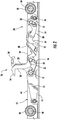
FIGS. 1 and2 , an example of acargo handling system 20 for use in an aircraft is illustrated. Thecargo handling system 20 is intended to mount to the cross beam of an aircraft cargo compartment, which is typically supported by an aircraft substructure. Thecargo handling system 20 includes a plurality ofstructural channels 22, also referred to as roller channels or trays, an example of which is illustrated inFIGS. 1 and2 . In the illustrated, non-limiting embodiment, thestructural channel 22 is generally C-shaped (seeFIG. 5 ) and is oriented such that thehollow interior 24 of thestructural channel 22 faces vertically upward. - Each
structural channel 22 includes one ormore locking mechanisms 26 for locking one or more unit load devices (ULDs) in place relative to thesystem 20. As shown, one ormore locking mechanisms 26 are generally positioned at a central portion of thestructural channel 22; however,locking mechanisms 26 arranged at another location relative to thestructural channel 22 are also contemplated herein. In the illustrated, non-limiting embodiment, alocking mechanism 26 includes both afirst pawl 28 and asecond pawl 30. Thefirst pawl 28 is configured to rotate about afirst pin 31 relative to thestructural channel 22 between a first retracted position (FIG. 1 ) and a second engaged position (FIG. 2 ). Similarly, thesecond pawl 30 is configured to rotate about asecond pin 32 relative to thestructural channel 22 between a first retracted position and a second engaged position. In an embodiment, the first and thesecond pawl first pin 31 and thesecond pin 32 are separated from one another by a horizontal distance such that thefirst pawl 28 and thesecond pawl 30 are independently rotatable. In an embodiment, however, thepawls pawls - Each
pawl lip 34 configured to secure an adjacent cargo pallet (not shown) to thecargo handling system 20 when rotated to the engaged position. When the first andsecond pawl pawls lip 34 of thefirst pawl 28 extending in a first direction, and thelip 34 of thesecond pawl 30 extending in a second direction, such as opposite the first direction for example. In the engaged position, thepawls first pawl 28 engages a complementary feature on thesecond pawl 30 to limit unintended movement of thepawls lock base plate 33 of thelock mechanism 26 may restrict rotation of thepawls first pawl 28 and thesecond pawl 30 are configured to contactstoppers 35 and 37, respectively, to prevent rotation beyond a desired position when rotated towards the retracted position. It should be understood that thelocking mechanisms 26 illustrated and described herein are intended as an example only and that any suitable connector for securing cargo pallets to the structural channel is contemplated herein. - At least one
roller 38 is mounted within thehollow interior 24 of thestructural channel 22. As shown, each of a plurality ofrollers 38 is mounted about a shaft orpin 40 extending horizontally between opposing sides of thechannel 22. In an embodiment, the rotational axes of the plurality ofrollers 38, defined by the supportingshafts 40, are generally parallel. Further the rotational axes of therollers 38 may be parallel to a rotational axis of anadjacent locking mechanism 26. Anupper surface 42 of the plurality ofrollers 38 mounted to thestructural channel 22 define a conveyor plane P (FIG. 1 ) along which one or more ULDs are moved. Therollers 38 are configured to support the ULDs as they move within the plane P. In an embodiment, the plane P is generally parallel to and vertically offset from anupper surface 44 of thestructural channel 22. If therollers 38 are substantially identical, therollers 38 are generally mounted at a similar height relative to thestructural channel 22. However, embodiments where one or more of therollers 38 has a varied configuration, such as different diameter for example, are also contemplated herein, and the mounting position of therollers 38 relative tostructural channel 22 may vary accordingly. - Inclusion of a roller, such as
roller 38 for example, near alocking mechanism 26 helps maintain the position of a ULD adjacent thelocking mechanism 26, and reducing the risk of thelocking mechanism 26 decoupling from the ULD. As a result, the horizontal distance betweenadjacent rollers 38 should be less than about 12 inches (about 30.48 cm). In embodiments where twolocking mechanisms 26 are positioned relatively close to one another, such as less than 12 inches apart, and more specifically, between about 5 inches (about 12.7 cm) and about 7 inches (about 17.8cm) apart for example, aroller 38 cannot be located within thehollow channel 24 between thelocking mechanisms 26 due to the operational interference that would occur therewith. - With reference now to
FIGS. 3-5 , one or moreside roller assemblies 50 may be mounted to an exterior surface of thestructural channel 22 at a horizontal position disposed between the first andsecond locking mechanisms 26. In the illustrated, non-limiting embodiment, a firstside roller assembly 50 is mounted adjacent afirst side 46 of thestructural channel 22 and a secondside roller assembly 50 is mounted adjacent a second,opposite side 48 of thestructural channel 22. In embodiments including multipleside roller assemblies 50, the side roller assemblies may be substantially identical, or alternatively may be different. - An example of a
side roller assembly 50 is illustrated in more detail inFIGS. 6a-6c . Theside roller assembly 50 includes aside roller 52 rotatably coupled to a housing orbracket 54. In an embodiment, thehousing 54 defines ahollow interior 56 within which theside roller 52 is located. Theside roller 52 may be supported by a shaft or pin 58 extending through one or more portions of thehousing 54. For example, thepin 58 may extend through two portions of thehousing 54 arranged on opposite sides of thehollow interior 56. A clip orother retention mechanism 60 may be coupled to an end of thepin 58, generally adjacent a surface of thehousing 54 to restrict lateral movement of thepin 58 relative to thehousing 54. - In the non-limiting embodiment of
FIGS. 6A-6C , thehousing 54 includes one ormore flanges 62 for mounting to a surface of thestructural channel 22, such as thefirst side 46 orsecond side 48 thereof for example. In an embodiment, theflanges 62 are generally offset from the portion of thehousing 54 supporting theside roller 52. As a result, when theside roller assembly 50 is mounted to thestructural channel 22, such as via a bolt orother fastener 64 extending through theflange 62, a clearance exists between the side of thestructural channel 22 and the portion of thehousing 54 supporting theside roller 52. The at least oneflange 62 may include a generally planar surface having an orientation generally complementary to thestructural channel 22. In an embodiment, the at least oneflange 62 is configured such that when theside roller assembly 50 is mounted to thestructural channel 22, the axis of rotation defined by thepin 58 is generally parallel to the axis of rotation of therollers 38 mounted within thehollow interior 24 of thestructural channel 22. - Another embodiment of the
side roller assembly 50 is illustrated in inFIGS. 7A-7C . As previously described, theside roller assembly 50 includes aside roller 52 rotatably coupled to a housing orbracket 54. Theside roller 52 is supported within a hollow interior of thebracket 54 by a shaft or pin 58 extending there through, and aretention mechanism 60 may be coupled to thepin 58 to restrict lateral movement of thepin 58 relative to thehousing 54. In an embodiment, thehollow interior 56 of the portion of thehousing 54 that receives thepin 58 is narrower than other portions of thehousing 54 to restrict lateral movement of theside roller 52 along the axis defined by thepin 58. - At least one
surface 68 of thehousing 54, arranged within a plane, is configured to contact asurface structural channel 22 when mounted thereto. In the configuration of thehousing 54 ofFIGS. 7A-7C , the one ormore fasteners 64 are positioned within thehollow interior 56 and extend through thehousing 54, including the at least onesurface 68, and a portion of thestructural channel 22 to mount thehousing 54 to thestructural channel 22. Thehousing 54 may include at least onehole 70 formed in a sidewall thereof to allow a tool to be inserted into thehollow interior 56 to access the one ormore fasteners 64. - In an embodiment, a
spacer 72 is positioned within thehollow interior 24 of thestructural channel 22, adjacent the side roller assembly. Thespacer 72 may be a separate component, or may be integrally formed with thestructural channel 22. The spacer is sized and shaped such that the one ormore fasteners 64 are received within thespacer 72. - Regardless of the configuration of the
side roller assembly 50, in embodiments whereside roller assemblies 50 are mounted on opposing sides of thestructural channel 22, theside roller assemblies 50 may, but need not be, horizontally aligned. In general, theside roller assembly 50 should be positioned about thestructural channel 22 such that a distance between anadjacent pawl side roller 52 is less than or equal to about 2.5 inches. In addition, thehousing 54 should be positioned relative to thestructural channel 22 such that anupper surface 66 of theside roller 52 is aligned with the conveyor plane P defined by theother rollers 38. - Inclusion of at least one
side roller assembly 50 at a position between adjacent lockingmechanisms 26 provides added support for cargo located there between. As a result, the cargo is less likely to deflect below the conveyor plane P defined by the plurality of rollers and cause one of the lockingmechanisms 26 to disengage from an adjacent ULD. - While the present disclosure has been described in detail in connection with only a limited number of embodiments, it should be readily understood that the present disclosure is not limited to such disclosed embodiments. Rather, the present disclosure can be modified to incorporate any number of variations, alterations, substitutions or equivalent arrangements not heretofore described, but which are commensurate with the spirit and scope of the present disclosure. Additionally, while various embodiments of the present disclosure have been described, it is to be understood that aspects of the present disclosure may include only some of the described embodiments. Accordingly, the present disclosure is not to be seen as limited by the foregoing description, but is only limited by the scope of the appended claims.
Claims (15)
- A cargo handling system for restraining a unit load device comprising:a structural channel having a hollow interior;at least one roller rotatably mounted within said hollow interior;at least one locking mechanism associated with said structural channel, said at least one locking mechanism being movable to engage the unit load device; andat least one side roller assembly operably coupled to an exterior surface of said structural channel, said at least one side roller assembly including a side roller, said side roller being positioned such that said an upper surface of said at least one roller and an upper surface of said side roller are disposed within a plane for supporting said unit load device.
- The cargo handling system according to claim 1, wherein said plane defined by said at least one roller and said side roller is vertically offset from an upper surface of said structural channel.
- The cargo handling system according to claim 1 or 2, wherein said plane defined by said at least one roller and said side roller is generally parallel to an upper surface of said structural channel.
- The cargo handling system according to claim 1, 2 or 3, wherein said at least one locking mechanism includes a first locking mechanism and a second locking mechanism, and said side roller assembly is mounted to said structural channel at a position between said first locking mechanism and said second locking mechanism.
- The cargo handling system according to claim 4, wherein said at least one side roller assembly is separated from at least one of said first locking mechanism and said second locking mechanism by a distance less than or equal to about 2.5 inches.
- The cargo handling system according to any preceding claim, wherein said at least one side roller assembly includes a first side roller assembly mounted to a first side of said structural channel and a second side roller assembly mounted to a second, opposite side of said structural channel.
- The cargo handling system according to claim 6, wherein said first side roller assembly and said second side roller assembly are generally horizontally aligned.
- The cargo handling system according to any preceding claim, wherein said at least one side roller assembly further comprises a housing associated with said side roller, said housing defines a hollow interior within which said side roller is located.
- The cargo handling system according to claim 8, wherein a clearance exists between said external surface of said structural channel and said side roller.
- The cargo handling system according to claim 8 or 9, wherein said side roller assembly further comprises:a shaft for rotatably mounting said side roller to said housing; anda retention mechanism mounted to said shaft adjacent said housing to restrict lateral movement of said shaft relative to said housing.
- The cargo handling system according to claim 8, 9 or 10, wherein said housing further comprises a flange for mounting said housing to said exterior surface of said structural channel.
- The cargo handling system according to claim 11, wherein said flange is mounted to said structural channel with at least one fastener.
- The cargo handling system according to any of claims 8 to 12, wherein at least one fastener positioned within said hollow interior mounts said housing to said structural channel.
- The cargo handling system according to claim 13, wherein said housing includes at least one hole formed therein for accessing said at least one fastener with a tool.
- The cargo handling system according to claim 13 or 14, wherein said structural channel further comprises a spacer arranged within an interior thereof, said spacer positioned to receive said at least one fastener.
Applications Claiming Priority (1)
| Application Number | Priority Date | Filing Date | Title |
|---|---|---|---|
| IN201611043061 | 2016-12-16 |
Publications (2)
| Publication Number | Publication Date |
|---|---|
| EP3335990A1 true EP3335990A1 (en) | 2018-06-20 |
| EP3335990B1 EP3335990B1 (en) | 2020-09-02 |
Family
ID=60673723
Family Applications (1)
| Application Number | Title | Priority Date | Filing Date |
|---|---|---|---|
| EP17207801.6A Active EP3335990B1 (en) | 2016-12-16 | 2017-12-15 | Side roller assembly for cargo handling system |
Country Status (2)
| Country | Link |
|---|---|
| US (1) | US20180170546A1 (en) |
| EP (1) | EP3335990B1 (en) |
Citations (5)
| Publication number | Priority date | Publication date | Assignee | Title |
|---|---|---|---|---|
| US20050224645A1 (en) * | 2004-03-22 | 2005-10-13 | Telair International Gmbh | Cargo deck |
| WO2008091287A2 (en) * | 2006-08-22 | 2008-07-31 | The Boeing Company | Cargo transport system and method |
| US20100230230A1 (en) * | 2009-03-10 | 2010-09-16 | Telair International Gmbh | Roller Conveyor |
| US20100264267A1 (en) * | 2006-12-21 | 2010-10-21 | Christoph Barauke | Fixing rail for attaching loading devices to the loading deck of an aircraft |
| US20130166063A1 (en) * | 2010-08-23 | 2013-06-27 | Airbus Operations Gmbh | Fully automated cargo loading system |
-
2017
- 2017-02-23 US US15/440,770 patent/US20180170546A1/en not_active Abandoned
- 2017-12-15 EP EP17207801.6A patent/EP3335990B1/en active Active
Patent Citations (5)
| Publication number | Priority date | Publication date | Assignee | Title |
|---|---|---|---|---|
| US20050224645A1 (en) * | 2004-03-22 | 2005-10-13 | Telair International Gmbh | Cargo deck |
| WO2008091287A2 (en) * | 2006-08-22 | 2008-07-31 | The Boeing Company | Cargo transport system and method |
| US20100264267A1 (en) * | 2006-12-21 | 2010-10-21 | Christoph Barauke | Fixing rail for attaching loading devices to the loading deck of an aircraft |
| US20100230230A1 (en) * | 2009-03-10 | 2010-09-16 | Telair International Gmbh | Roller Conveyor |
| US20130166063A1 (en) * | 2010-08-23 | 2013-06-27 | Airbus Operations Gmbh | Fully automated cargo loading system |
Also Published As
| Publication number | Publication date |
|---|---|
| EP3335990B1 (en) | 2020-09-02 |
| US20180170546A1 (en) | 2018-06-21 |
Similar Documents
| Publication | Publication Date | Title |
|---|---|---|
| US11117645B2 (en) | Cargo hold component system for convertible cargo hold | |
| US9376210B2 (en) | Cargo handling system | |
| US9242730B2 (en) | Sequential latch for palletized cargo | |
| US4077590A (en) | Integrated treadway cargo handling system | |
| US8757944B2 (en) | Adjustable decking system for supporting freight | |
| US5011348A (en) | Automatically retractable centerline restraint | |
| US20030031523A1 (en) | Method for vertically restraining aircargo pallets within an aircraft | |
| US8979450B2 (en) | Function element, method for producing a function element | |
| EP1499543B1 (en) | Device for adapting a cargo container to directly interface with an aircraft cargo bay | |
| JP6523341B2 (en) | Device, system and method for limiting movement of cargo containers in a cargo area | |
| US10494142B2 (en) | Pallet adapter | |
| JP2004359227A (en) | Holding device for holding anchor device for cargo loading system of conveyance means, especially aeroplane | |
| WO2018034865A1 (en) | Captive beam sytem with rotating latch | |
| US8925861B2 (en) | Locking element | |
| JP2022547160A (en) | transport vehicle | |
| US8337127B2 (en) | Latch arrangement for cargo restraint | |
| EP3335990A1 (en) | Side roller assembly for cargo handling system | |
| EP2566738B1 (en) | Dual pivot pallet type cargo load restraint | |
| US6315141B1 (en) | Shipping box lockdown | |
| US9796324B2 (en) | Multi-use panel for bulkhead | |
| US12600287B2 (en) | Systems and methods for restraining carts and other cargo using forward and rearward brackets | |
| CN210504013U (en) | Integral self-loading and unloading transportation square bin of 4560 soft oil tank of air-drop oil equipment | |
| US12497171B2 (en) | System consisting of catch elements and freight carriers | |
| US10000149B2 (en) | Container-securing device | |
| GB2446816A (en) | An assembly for engaging a tie-down ring |
Legal Events
| Date | Code | Title | Description |
|---|---|---|---|
| PUAI | Public reference made under article 153(3) epc to a published international application that has entered the european phase |
Free format text: ORIGINAL CODE: 0009012 |
|
| STAA | Information on the status of an ep patent application or granted ep patent |
Free format text: STATUS: THE APPLICATION HAS BEEN PUBLISHED |
|
| AK | Designated contracting states |
Kind code of ref document: A1 Designated state(s): AL AT BE BG CH CY CZ DE DK EE ES FI FR GB GR HR HU IE IS IT LI LT LU LV MC MK MT NL NO PL PT RO RS SE SI SK SM TR |
|
| AX | Request for extension of the european patent |
Extension state: BA ME |
|
| STAA | Information on the status of an ep patent application or granted ep patent |
Free format text: STATUS: REQUEST FOR EXAMINATION WAS MADE |
|
| 17P | Request for examination filed |
Effective date: 20181220 |
|
| RBV | Designated contracting states (corrected) |
Designated state(s): AL AT BE BG CH CY CZ DE DK EE ES FI FR GB GR HR HU IE IS IT LI LT LU LV MC MK MT NL NO PL PT RO RS SE SI SK SM TR |
|
| STAA | Information on the status of an ep patent application or granted ep patent |
Free format text: STATUS: EXAMINATION IS IN PROGRESS |
|
| 17Q | First examination report despatched |
Effective date: 20190521 |
|
| GRAP | Despatch of communication of intention to grant a patent |
Free format text: ORIGINAL CODE: EPIDOSNIGR1 |
|
| STAA | Information on the status of an ep patent application or granted ep patent |
Free format text: STATUS: GRANT OF PATENT IS INTENDED |
|
| INTG | Intention to grant announced |
Effective date: 20200323 |
|
| GRAS | Grant fee paid |
Free format text: ORIGINAL CODE: EPIDOSNIGR3 |
|
| GRAA | (expected) grant |
Free format text: ORIGINAL CODE: 0009210 |
|
| STAA | Information on the status of an ep patent application or granted ep patent |
Free format text: STATUS: THE PATENT HAS BEEN GRANTED |
|
| AK | Designated contracting states |
Kind code of ref document: B1 Designated state(s): AL AT BE BG CH CY CZ DE DK EE ES FI FR GB GR HR HU IE IS IT LI LT LU LV MC MK MT NL NO PL PT RO RS SE SI SK SM TR |
|
| REG | Reference to a national code |
Ref country code: GB Ref legal event code: FG4D |
|
| REG | Reference to a national code |
Ref country code: AT Ref legal event code: REF Ref document number: 1308540 Country of ref document: AT Kind code of ref document: T Effective date: 20200915 Ref country code: CH Ref legal event code: EP |
|
| REG | Reference to a national code |
Ref country code: DE Ref legal event code: R096 Ref document number: 602017022718 Country of ref document: DE |
|
| REG | Reference to a national code |
Ref country code: IE Ref legal event code: FG4D |
|
| REG | Reference to a national code |
Ref country code: LT Ref legal event code: MG4D |
|
| PG25 | Lapsed in a contracting state [announced via postgrant information from national office to epo] |
Ref country code: SE Free format text: LAPSE BECAUSE OF FAILURE TO SUBMIT A TRANSLATION OF THE DESCRIPTION OR TO PAY THE FEE WITHIN THE PRESCRIBED TIME-LIMIT Effective date: 20200902 Ref country code: BG Free format text: LAPSE BECAUSE OF FAILURE TO SUBMIT A TRANSLATION OF THE DESCRIPTION OR TO PAY THE FEE WITHIN THE PRESCRIBED TIME-LIMIT Effective date: 20201202 Ref country code: NO Free format text: LAPSE BECAUSE OF FAILURE TO SUBMIT A TRANSLATION OF THE DESCRIPTION OR TO PAY THE FEE WITHIN THE PRESCRIBED TIME-LIMIT Effective date: 20201202 Ref country code: LT Free format text: LAPSE BECAUSE OF FAILURE TO SUBMIT A TRANSLATION OF THE DESCRIPTION OR TO PAY THE FEE WITHIN THE PRESCRIBED TIME-LIMIT Effective date: 20200902 Ref country code: HR Free format text: LAPSE BECAUSE OF FAILURE TO SUBMIT A TRANSLATION OF THE DESCRIPTION OR TO PAY THE FEE WITHIN THE PRESCRIBED TIME-LIMIT Effective date: 20200902 Ref country code: FI Free format text: LAPSE BECAUSE OF FAILURE TO SUBMIT A TRANSLATION OF THE DESCRIPTION OR TO PAY THE FEE WITHIN THE PRESCRIBED TIME-LIMIT Effective date: 20200902 |
|
| REG | Reference to a national code |
Ref country code: NL Ref legal event code: MP Effective date: 20200902 |
|
| REG | Reference to a national code |
Ref country code: AT Ref legal event code: MK05 Ref document number: 1308540 Country of ref document: AT Kind code of ref document: T Effective date: 20200902 |
|
| PG25 | Lapsed in a contracting state [announced via postgrant information from national office to epo] |
Ref country code: PL Free format text: LAPSE BECAUSE OF FAILURE TO SUBMIT A TRANSLATION OF THE DESCRIPTION OR TO PAY THE FEE WITHIN THE PRESCRIBED TIME-LIMIT Effective date: 20200902 Ref country code: LV Free format text: LAPSE BECAUSE OF FAILURE TO SUBMIT A TRANSLATION OF THE DESCRIPTION OR TO PAY THE FEE WITHIN THE PRESCRIBED TIME-LIMIT Effective date: 20200902 Ref country code: RS Free format text: LAPSE BECAUSE OF FAILURE TO SUBMIT A TRANSLATION OF THE DESCRIPTION OR TO PAY THE FEE WITHIN THE PRESCRIBED TIME-LIMIT Effective date: 20200902 |
|
| PG25 | Lapsed in a contracting state [announced via postgrant information from national office to epo] |
Ref country code: CZ Free format text: LAPSE BECAUSE OF FAILURE TO SUBMIT A TRANSLATION OF THE DESCRIPTION OR TO PAY THE FEE WITHIN THE PRESCRIBED TIME-LIMIT Effective date: 20200902 Ref country code: RO Free format text: LAPSE BECAUSE OF FAILURE TO SUBMIT A TRANSLATION OF THE DESCRIPTION OR TO PAY THE FEE WITHIN THE PRESCRIBED TIME-LIMIT Effective date: 20200902 Ref country code: PT Free format text: LAPSE BECAUSE OF FAILURE TO SUBMIT A TRANSLATION OF THE DESCRIPTION OR TO PAY THE FEE WITHIN THE PRESCRIBED TIME-LIMIT Effective date: 20210104 Ref country code: SM Free format text: LAPSE BECAUSE OF FAILURE TO SUBMIT A TRANSLATION OF THE DESCRIPTION OR TO PAY THE FEE WITHIN THE PRESCRIBED TIME-LIMIT Effective date: 20200902 Ref country code: EE Free format text: LAPSE BECAUSE OF FAILURE TO SUBMIT A TRANSLATION OF THE DESCRIPTION OR TO PAY THE FEE WITHIN THE PRESCRIBED TIME-LIMIT Effective date: 20200902 |
|
| PG25 | Lapsed in a contracting state [announced via postgrant information from national office to epo] |
Ref country code: IS Free format text: LAPSE BECAUSE OF FAILURE TO SUBMIT A TRANSLATION OF THE DESCRIPTION OR TO PAY THE FEE WITHIN THE PRESCRIBED TIME-LIMIT Effective date: 20210102 Ref country code: AL Free format text: LAPSE BECAUSE OF FAILURE TO SUBMIT A TRANSLATION OF THE DESCRIPTION OR TO PAY THE FEE WITHIN THE PRESCRIBED TIME-LIMIT Effective date: 20200902 Ref country code: AT Free format text: LAPSE BECAUSE OF FAILURE TO SUBMIT A TRANSLATION OF THE DESCRIPTION OR TO PAY THE FEE WITHIN THE PRESCRIBED TIME-LIMIT Effective date: 20200902 Ref country code: ES Free format text: LAPSE BECAUSE OF FAILURE TO SUBMIT A TRANSLATION OF THE DESCRIPTION OR TO PAY THE FEE WITHIN THE PRESCRIBED TIME-LIMIT Effective date: 20200902 |
|
| REG | Reference to a national code |
Ref country code: DE Ref legal event code: R097 Ref document number: 602017022718 Country of ref document: DE |
|
| PG25 | Lapsed in a contracting state [announced via postgrant information from national office to epo] |
Ref country code: SK Free format text: LAPSE BECAUSE OF FAILURE TO SUBMIT A TRANSLATION OF THE DESCRIPTION OR TO PAY THE FEE WITHIN THE PRESCRIBED TIME-LIMIT Effective date: 20200902 |
|
| PLBE | No opposition filed within time limit |
Free format text: ORIGINAL CODE: 0009261 |
|
| STAA | Information on the status of an ep patent application or granted ep patent |
Free format text: STATUS: NO OPPOSITION FILED WITHIN TIME LIMIT |
|
| REG | Reference to a national code |
Ref country code: CH Ref legal event code: PL |
|
| 26N | No opposition filed |
Effective date: 20210603 |
|
| PG25 | Lapsed in a contracting state [announced via postgrant information from national office to epo] |
Ref country code: MC Free format text: LAPSE BECAUSE OF FAILURE TO SUBMIT A TRANSLATION OF THE DESCRIPTION OR TO PAY THE FEE WITHIN THE PRESCRIBED TIME-LIMIT Effective date: 20200902 Ref country code: DK Free format text: LAPSE BECAUSE OF FAILURE TO SUBMIT A TRANSLATION OF THE DESCRIPTION OR TO PAY THE FEE WITHIN THE PRESCRIBED TIME-LIMIT Effective date: 20200902 Ref country code: SI Free format text: LAPSE BECAUSE OF FAILURE TO SUBMIT A TRANSLATION OF THE DESCRIPTION OR TO PAY THE FEE WITHIN THE PRESCRIBED TIME-LIMIT Effective date: 20200902 |
|
| REG | Reference to a national code |
Ref country code: BE Ref legal event code: MM Effective date: 20201231 |
|
| PG25 | Lapsed in a contracting state [announced via postgrant information from national office to epo] |
Ref country code: IT Free format text: LAPSE BECAUSE OF FAILURE TO SUBMIT A TRANSLATION OF THE DESCRIPTION OR TO PAY THE FEE WITHIN THE PRESCRIBED TIME-LIMIT Effective date: 20200902 Ref country code: LU Free format text: LAPSE BECAUSE OF NON-PAYMENT OF DUE FEES Effective date: 20201215 Ref country code: IE Free format text: LAPSE BECAUSE OF NON-PAYMENT OF DUE FEES Effective date: 20201215 |
|
| PG25 | Lapsed in a contracting state [announced via postgrant information from national office to epo] |
Ref country code: CH Free format text: LAPSE BECAUSE OF NON-PAYMENT OF DUE FEES Effective date: 20201231 Ref country code: LI Free format text: LAPSE BECAUSE OF NON-PAYMENT OF DUE FEES Effective date: 20201231 |
|
| PG25 | Lapsed in a contracting state [announced via postgrant information from national office to epo] |
Ref country code: TR Free format text: LAPSE BECAUSE OF FAILURE TO SUBMIT A TRANSLATION OF THE DESCRIPTION OR TO PAY THE FEE WITHIN THE PRESCRIBED TIME-LIMIT Effective date: 20200902 Ref country code: MT Free format text: LAPSE BECAUSE OF FAILURE TO SUBMIT A TRANSLATION OF THE DESCRIPTION OR TO PAY THE FEE WITHIN THE PRESCRIBED TIME-LIMIT Effective date: 20200902 Ref country code: CY Free format text: LAPSE BECAUSE OF FAILURE TO SUBMIT A TRANSLATION OF THE DESCRIPTION OR TO PAY THE FEE WITHIN THE PRESCRIBED TIME-LIMIT Effective date: 20200902 |
|
| PG25 | Lapsed in a contracting state [announced via postgrant information from national office to epo] |
Ref country code: MK Free format text: LAPSE BECAUSE OF FAILURE TO SUBMIT A TRANSLATION OF THE DESCRIPTION OR TO PAY THE FEE WITHIN THE PRESCRIBED TIME-LIMIT Effective date: 20200902 |
|
| PG25 | Lapsed in a contracting state [announced via postgrant information from national office to epo] |
Ref country code: GR Free format text: LAPSE BECAUSE OF FAILURE TO SUBMIT A TRANSLATION OF THE DESCRIPTION OR TO PAY THE FEE WITHIN THE PRESCRIBED TIME-LIMIT Effective date: 20200902 Ref country code: BE Free format text: LAPSE BECAUSE OF NON-PAYMENT OF DUE FEES Effective date: 20201231 |
|
| P01 | Opt-out of the competence of the unified patent court (upc) registered |
Effective date: 20230522 |
|
| PG25 | Lapsed in a contracting state [announced via postgrant information from national office to epo] |
Ref country code: NL Free format text: LAPSE BECAUSE OF NON-PAYMENT OF DUE FEES Effective date: 20200923 |
|
| PGFP | Annual fee paid to national office [announced via postgrant information from national office to epo] |
Ref country code: DE Payment date: 20251126 Year of fee payment: 9 |
|
| PGFP | Annual fee paid to national office [announced via postgrant information from national office to epo] |
Ref country code: GB Payment date: 20251120 Year of fee payment: 9 |
|
| PGFP | Annual fee paid to national office [announced via postgrant information from national office to epo] |
Ref country code: FR Payment date: 20251120 Year of fee payment: 9 |