EP3335970A1 - Folding personal mobility vehicle - Google Patents
Folding personal mobility vehicle Download PDFInfo
- Publication number
- EP3335970A1 EP3335970A1 EP17205317.5A EP17205317A EP3335970A1 EP 3335970 A1 EP3335970 A1 EP 3335970A1 EP 17205317 A EP17205317 A EP 17205317A EP 3335970 A1 EP3335970 A1 EP 3335970A1
- Authority
- EP
- European Patent Office
- Prior art keywords
- foothold
- handle
- locking
- folded
- hinge
- Prior art date
- Legal status (The legal status is an assumption and is not a legal conclusion. Google has not performed a legal analysis and makes no representation as to the accuracy of the status listed.)
- Granted
Links
Images

Classifications
-
- B—PERFORMING OPERATIONS; TRANSPORTING
- B62—LAND VEHICLES FOR TRAVELLING OTHERWISE THAN ON RAILS
- B62K—CYCLES; CYCLE FRAMES; CYCLE STEERING DEVICES; RIDER-OPERATED TERMINAL CONTROLS SPECIALLY ADAPTED FOR CYCLES; CYCLE AXLE SUSPENSIONS; CYCLE SIDECARS, FORECARS, OR THE LIKE
- B62K3/00—Bicycles
- B62K3/002—Bicycles without a seat, i.e. the rider operating the vehicle in a standing position, e.g. non-motorized scooters; non-motorized scooters with skis or runners
-
- B—PERFORMING OPERATIONS; TRANSPORTING
- B62—LAND VEHICLES FOR TRAVELLING OTHERWISE THAN ON RAILS
- B62J—CYCLE SADDLES OR SEATS; AUXILIARY DEVICES OR ACCESSORIES SPECIALLY ADAPTED TO CYCLES AND NOT OTHERWISE PROVIDED FOR, e.g. ARTICLE CARRIERS OR CYCLE PROTECTORS
- B62J50/00—Arrangements specially adapted for use on cycles not provided for in main groups B62J1/00 - B62J45/00
- B62J50/10—Means for carrying cycles by hand
-
- B—PERFORMING OPERATIONS; TRANSPORTING
- B62—LAND VEHICLES FOR TRAVELLING OTHERWISE THAN ON RAILS
- B62K—CYCLES; CYCLE FRAMES; CYCLE STEERING DEVICES; RIDER-OPERATED TERMINAL CONTROLS SPECIALLY ADAPTED FOR CYCLES; CYCLE AXLE SUSPENSIONS; CYCLE SIDECARS, FORECARS, OR THE LIKE
- B62K15/00—Collapsible or foldable cycles
- B62K15/006—Collapsible or foldable cycles the frame being foldable
-
- B—PERFORMING OPERATIONS; TRANSPORTING
- B62—LAND VEHICLES FOR TRAVELLING OTHERWISE THAN ON RAILS
- B62K—CYCLES; CYCLE FRAMES; CYCLE STEERING DEVICES; RIDER-OPERATED TERMINAL CONTROLS SPECIALLY ADAPTED FOR CYCLES; CYCLE AXLE SUSPENSIONS; CYCLE SIDECARS, FORECARS, OR THE LIKE
- B62K15/00—Collapsible or foldable cycles
- B62K15/006—Collapsible or foldable cycles the frame being foldable
- B62K15/008—Collapsible or foldable cycles the frame being foldable foldable about 2 or more axes
-
- B—PERFORMING OPERATIONS; TRANSPORTING
- B62—LAND VEHICLES FOR TRAVELLING OTHERWISE THAN ON RAILS
- B62K—CYCLES; CYCLE FRAMES; CYCLE STEERING DEVICES; RIDER-OPERATED TERMINAL CONTROLS SPECIALLY ADAPTED FOR CYCLES; CYCLE AXLE SUSPENSIONS; CYCLE SIDECARS, FORECARS, OR THE LIKE
- B62K21/00—Steering devices
- B62K21/12—Handlebars; Handlebar stems
- B62K21/16—Handlebars; Handlebar stems having adjustable parts therein
-
- B—PERFORMING OPERATIONS; TRANSPORTING
- B60—VEHICLES IN GENERAL
- B60Y—INDEXING SCHEME RELATING TO ASPECTS CROSS-CUTTING VEHICLE TECHNOLOGY
- B60Y2200/00—Type of vehicle
- B60Y2200/10—Road Vehicles
- B60Y2200/12—Motorcycles, Trikes; Quads; Scooters
- B60Y2200/126—Scooters
Definitions
- the present invention relates to a folding personal mobility vehicle, more particularly, to a technology for folding personal mobility vehicle which may be easily carried and stored even in a narrow space.
- the kick board largely includes a foothold part provided with a wheel and a handle part provided with a handle and a length of the handle part is generally longer than that of the foothold part.
- a personal mobility vehicle having a length-varying structure like a sliding type has a minimum overlapping section along a longitudinal direction in which it is slid in order to secure rigidity. Therefore, as the length is not reduced to the maximum due to the overlapping section, there is still a disadvantage in that the personal mobility vehicle takes up a lot of space for storage.
- a folding structure of a general hinge type has an empty space present between components that are folded to overlap. Therefore, as a volume is not reduced to the minimum even in the folded state due to the empty space, there is still a disadvantage in that the personal mobility vehicle also takes up a lot of space for storage.
- Embodiments of the present invention relate to a folding personal mobility vehicle and particular embodiments relate to a folding personal mobility vehicle that may be easily carried and stored even in a narrow space.
- Embodiments of the present invention provide a folding personal mobility vehicle having a hinge structure capable of preventing an empty space from being present between components overlapping in a folded state to minimize a volume of the folded state, thereby being effectively stored even in a narrow space and easily carried.
- folding personal mobility vehicle includes: : a foothold part provided with a wheel and having a front foothold part and a rear foothold part, with the front foothold part 110 and the rear foothold part being connected to each other by a hinge structure to be folded against each other; and a handle part provided with a handle and folded by the hinge structure, wherein the rear foothold part is folded on the front foothold part by the hinge structure and the handle part is folded on the rear foothold part by the hinge structure, such that the rear foothold part is positioned between the handle part and the front foothold part while being folded.
- the handle part and the rear foothold part, and the rear foothold part and the front foothold part may be stacked side by side and adhere to each other.
- the handle In the state in which the rear foothold part is folded to be positioned between the handle part and the front foothold part, the handle may be folded to adhere to a side of the handle part.
- folding personal mobility vehicle includes: a foothold part having a front foothold part whose front portion is provided with a wheel carrier provided with a front wheel and the rear foothold part whose rear portion is provided with a rear wheel, the front foothold part and the rear foothold part being rotatably coupled to each other with respect to a hinge shaft; and a handle part provided with a handle and coupled to a wheel carrier by the hinge locking mechanism, in which the rear foothold part rotates with respect to the hinge shaft to be folded on the front foothold part and the handle part may rotate with respect to the hinge locking mechanism to be folded on the rear foothold part, such that the rear foothold part is positioned between the handle part and the front foothold part while being folded.
- the folding personal mobility vehicle may further include: a foothold locking mechanism provided on the foothold part to fix an unfolded state of the front foothold part and the rear foothold part.
- the handle part may include a lower handle part coupled with the wheel carrier by a hinge locking mechanism, a middle handle part coupled with the lower handle part by the hinge locking mechanism, and an upper handle part coupled with the middle handle part by the hinge locking mechanism, and the rear foothold part may be folded on the front foothold part, the lower handle part may be folded on the rear foothold part, and the middle handle part may be folded to be positioned at a rear of the front foothold part and the rear foothold part, and the upper handle part may be folded on a lower portion of the front foothold part.
- the middle handle part may be provided with a carrying handle, and the carrying handle may protrude rearward outward while being folded so that the middle handle part is positioned at positioned at the rear of the front foothold part and the rear foothold part.
- An upper front of the front foothold part may be provided with a wheel groove into which a rear wheel is inserted when the rear foothold part is folded on the front foothold part.
- the upper handle part may be coupled to the handle by the hinge locking mechanism and the handle may be folded on both sides of the upper handle part.
- the lower handle part, the middle handle part, the upper handle part, and the handles that are in the folded state may be maintained in a folded state by the hinge locking mechanism.
- the handle part may be connected to the wheel carrier by the hinge part, the hinge part may have a left flange and a right flange provided at left and right sides thereof, with an inner flange interposed therebetween, the left flange and the right flange may be connected to each other and may be separated from the inner flange, and an overlapping portion of the inner flange and the left flange and the right flange may be provided with the hinge locking mechanism.
- the lower handle part, the middle handle part, the upper handle part, and the handle may be provided with the hinge part
- the hinge part may have a left flange and a right flange provided at left and right sides thereof, with an inner flange interposed therebetween, the left flange and the right flange may be connected to each other and may be separated from the inner flange, and an overlapping portion of the inner flange and the left flange and the right flange may be provided with the hinge locking mechanism.
- the hinge locking mechanism may include a locking pin having a pressing part of one end and a locking part of the other end and a rod part connecting between the pressing part and the locking part and a locking spring for elastically supporting the locking part of the locking pin, in which the pressing part may be installed to be movable along a longitudinal direction of the rod part while being inserted into an operating groove formed at the right flange, the locking part may be installed to be separated from the locking groove at the time of pressing the pressing part while being installed to be simultaneously inserted into the locking groove formed at the inner flange and a release groove formed at the left flange, the rod part may be installed to connect between the pressing part and the locking part by penetrating through the right flange and the inner flange, and the locking spring may have one end supported to the locking part and the other end supported into the release groove and thus may be a compression spring for pressing the locking part toward the pressing part by the accumulated elastic force.
- the left flange and the right flange may relatively rotate with respect to the inner flange based on the rod part, and the folding operation of the handle part may be enabled by the relative rotation of the left flange and the right flange.
- a rear upper edge part of the front foothold part and a front upper edge part of the rear foothold part may be rotatably coupled with each other with respect to the hinge shaft while overlapping with each other.
- the foothold locking mechanism may include a locking lever rotatably installed at a rear lower edge part of the front foothold part with respect to a lever shaft, a locking protruding groove formed at a front lower edge part of the rear foothold part so that a locking protrusion formed at one end of the locking lever is inserted into the locking protruding groove and locked, and a lever spring having one end fixed to the front foothold part and the other end fixed to the lever shaft while being wound around the lever shaft and applying an elastic force so that the locking lever rotates in a direction in which the locking protrusion is inserted into the locking protruding groove.
- the upper handle part may be unfolded to extend in a longitudinal direction of the front foothold part while not being folded downward of the front foothold part.
- folding personal mobility vehicle includes: a foothold part 100 provided with a wheel 10 and having a front foothold part 110 and a rear foothold part 120, with the front foothold part 110 and the rear foothold part 120 being connected to each other by a hinge structure to be folded against each other; and a handle part 200 provided with a handle 20 and folded by the hinge structure, in which the rear foothold part 130 is folded on the front foothold part 110 by the hinge structure and the handle part 200 is folded on the rear foothold part 130 by the hinge structure, such that the rear foothold part 130 is positioned between the handle part 200 and the front foothold part 110 while being the folded.
- the handle part 200 and the rear foothold part 130, and the rear foothold part 130 and the front foothold part 110 are stacked side by side and adhere to each other to prevent an empty space from being formed. That is, in the state in which the rear foothold part 130 is folded to be positioned between the handle part 200 and the front foothold part 110, the handle 20 is folded to adhere to a side of the handle part 200
- the folding personal mobility vehicle includes: a foothold part 100 having the front foothold part 110 whose front portion is provided with the wheel carrier 30 provided with a front wheel 11 and the rear foothold part 130 whose rear portion is provided with a rear wheel 12, the front foothold part 110 and the rear foothold part 130 being rotatably coupled to each other with respect to a hinge shaft 120; and the handle part 200 provided with the handle 20 and coupled to the wheel carrier 30 by a hinge locking mechanism 40, in which the rear foothold part 130 rotates with respect to the hinge shaft 120 to be folded on the front foothold part 110 and the handle part 200 rotates with respect to the hinge locking mechanism 40 to be folded on the rear foothold part 130, such that the rear foothold part 130 is positioned between the handle part 200 and the front foothold part 110 while being folded.
- the handle part 200 includes a lower handle part 210 coupled to the wheel carrier 30 by the hinge locking mechanism 40, a middle handle part 220 coupled to the lower handle part 210 by the hinge locking mechanism 40, and an upper handle part 230 coupled to the middle handle part 220 by the hinge locking mechanism 40, in which the rear foothold part 130 is folded on the front foothold part 110, the lower handle part 210 is folded on the rear foothold part 310, and the middle handle part 220 is folded to be positioned at a rear of the front foothold part 110 and the rear foothold part 130, and the upper handle part 230 is folded on a lower portion of the front foothold part 110.
- the handle 20 is provided on both sides of the upper handle part 230 by the hinge locking mechanism 40.
- the handle 20 is folded on both sides of the upper handle part 230.
- the folding personal mobility vehicle further includes a foothold locking mechanism 50 provided on the foothold part 100 to fix the unfolded state of the front foothold part 110 and the rear foothold part 130 and has a structure in which the middle handle part 220 is coupled with a carrying handle 300.
- the carrying handle 300 protrudes rearward outward while being folded so that the middle handle part 220 is positioned at the rear of the front foothold part 110 and the rear foothold part 130.
- a wheel groove 111 opened upward is formed at the front of the front foothold part 110 and the wheel groove 111 is inserted with the rear wheel 12 when the rear foothold part 130 is folded so that the rear foothold part 130 adheres to the front foothold part 110.
- the folding personal mobility vehicle according to the exemplary embodiment of the present invention has a structure in which the folding personal mobility vehicle may be in the unfolded state (used state) as illustrated in FIG. 1 and may be in the folded state (carried and stored state) as illustrated in FIG. 4 . In the state in which the folding personal mobility vehicle is unfolded as illustrated in FIG.
- the folding personal mobility vehicle is in an overlapping state by being completely folded as illustrated in FIG. 6 , and in the state in which the folding personal mobility vehicle is folded as illustrated in FIG.
- the lower handle part 210 and the rear foothold part 130 completely adhere to each other
- the rear foothold part 130 and the front foothold part 110 completely adhere to each other
- the front foothold part 110 and the upper handle part 230 completely adhere to each other to prevent an empty space from being present between the lower handle part 210 and the rear foothold part 130, between the rear foothold part 130 and the front foothold part 110, and between the front foothold part 110 and the upper handle part 230 to minimize the volume of the folded state, such that the folding personal mobility vehicle may be effectively stored even in the narrow space and easily carried.
- the lower handle part 210 and the middle handle part 220 and the upper handle part 230 and the handle 20 that are in the folded state as described above are each maintained in a folded state by the hinge locking mechanism 40.
- the handle part 200 is connected to the wheel carrier 30 by the hinge part 400.
- the hinge part 400 has a left flange 420 and a right flange 430 provided at left and right sides thereof, with an inner flange 410 interposed therebetween.
- the left flange 420 and the right flange 430 are connected to each other and are separated from the inner flange 410.
- the overlapping portion of the inner flange 410 and the left flange 420 and the right flange 430 are provided with the hinge locking mechanism 40.
- an upper end of the wheel carrier 30 and a lower end of the lower handle part 210, an upper end of the lower handle part 210 and a lower end of the middle handle part 220, an upper end of the middle handle part 220 and a lower end of the upper handle part 230, and an upper end of the upper handle part 230 and one end of the handle 20 each are a hinge part 400 that may implement the folding operation and the unfolding operation of the handle part 200
- the hinge part 400 is configured so that a left flange 420 and a right flange 430 overlap with each other at left and right sides, having an inner flange 410 disposed therebetween, the left flange 420 and the right flange 430 are configured to be separated from the inner flange 410 while having an integrated structure in which they are connected to each other like a yoke shape
- the hinge locking mechanism 40 is installed at a part where the inner flange 410, the left flange 420, and the right flange 430 overlap with each other.
- the hinge locking mechanism 40 includes a locking pin 41 having a pressing part 41a of one end and a locking part 41b of the other end and a rod part 41c connecting between the pressing part 41a and the locking part 41b and a locking spring 42 for elastically supporting the locking part 41b of the locking pin 41.
- the pressing part 41a is installed to be movable along a longitudinal direction of the rod part 41c while being inserted into an operating groove 431 formed at the right flange 430
- the locking part 41b is installed to be separated from the locking groove 411 at the time of pressing the pressing part 41a while being installed to be simultaneously inserted into the locking groove 411 formed at the inner flange 410 and a release groove 421 formed at the left flange 420
- the rod part 41c is installed to connect between the pressing part 41a and the locking part 41b by penetrating through the right flange 430 and the inner flange 410.
- the locking spring 42 has one end supported to the locking part 41b and the other end supported into the release groove 421 and thus is a compression spring for pressing the locking part 41b toward the pressing part 41a by the accumulated elastic force.
- the inner flange 410 and the left flange 420 and the right flange 430 may relatively rotate with respect to the rod part 41c.
- the folding operation of the handle part 200 may be implemented by the relative rotation between the inner flange 410 and the left flange 420 and the right flange 430.
- the locking part 41b and the locking groove 411 have an outer circumference having a quadrangular cross section and thus the locking part 41b rotates by 90° when the inner flange 410 and the left flange 420 and the right flange 430 relatively rotate with respect to the rod part 41c and then are maintained in the locked state again, that is, the locking part 41b rotates by 90° in the state in which it is released from the locking groove 411 and then the locking part 41b is inserted into the locking groove 411 again, such that they may be maintained in the locked state again.
- a rear upper edge part of the front foothold part 110 and a front upper edge part of the rear foothold part 130 are rotatably coupled with each other via the hinge shaft 120 while overlapping with each other and the foothold locking mechanism 50 is installed under the hinge shaft 120.
- the foothold locking mechanism 50 includes a locking lever 52 rotatably installed at a rear lower edge part of the front foothold part 110 via a lever shaft 51, a locking protruding groove 53 formed at a front lower edge part of the rear foothold part 130 so that a locking protrusion 52a formed at one end of the locking lever 52 is inserted into the locking protruding groove 53 and locked, and a lever spring 54 having one end fixed to the front foothold part 110 and the other end fixed to the lever shaft 52 while being wound around the lever shaft 52 and applying an elastic force so that the locking lever 52 may rotate in a direction in which the locking protrusion 52a is inserted into the locking protruding groove 53, such that the lever spring 54 is the torsion spring.
- the rear foothold part 130 rotates upward with respect to the hinge shaft 120 so that the rear foothold part 130 adheres to the front foothold part 110.
- the foothold part 100 is folded as the rear wheel 12 is inserted into the wheel groove 111.
- the folding personal mobility vehicle As illustrated in FIG. 5 , when the rear foothold part 130 is folded to adhere to the front foothold part 110, the lower handle part 210 is folded to adhere to the rear foothold part 130, the middle handle part 220 is folded to be positioned at one side of the front foothold part 110 and the rear foothold part 130, and the upper handle part 230 is unfolded to extend along the longitudinal direction of the front foothold part 110, the user holds the handle 20 to bring the front wheel 11 into contact with a ground surface and then drag the folding personal mobility vehicle.
- the middle handle part 220 is folded to be positioned at one side of the front foothold part 110 and the rear foothold part 130, the upper handle part 230 is folded to adhere to the bottom surface of the front foothold part 110, the handle 20 is in the overlapping state by being completely folded to adhere to both side surfaces of the upper handle part 230, the user uses a carrying handle 300 provided at the middle handle part 220 to carry the folding personal mobility vehicle or store it in a luggage room or a trunk room of the vehicle.
- the upper handle part 230 is unfolded to extend in a longitudinal direction of the front foothold part 110 while not being folded downward of the front foothold part 110.
- the folding personal mobility vehicle according to the exemplary embodiment of the present invention including the foothold part 100 provided with the wheel 10 and the handle part 200 provided with the handle 20 like a kick board may prevent the empty space from being present between the lower handle part 210 and the rear foothold part 130, between the rear foothold part 130 and the front foothold part 110, and between the front foothold part 110 and the upper handle part 230 when being completely folded for carrying and storage to minimize the volume of the completely folded state, such that the folding personal mobility vehicle may be effectively stored even in the narrow space and easily carried.
- the folding personal mobility vehicle that includes the foothold part provided with the wheel and the handle part provided with the handle may prevent the empty space from being present between the lower handle part and the rear foothold part, between the rear foothold part and the front foothold part, and between the front foothold part and the upper handle part when being completely folded for carrying or storage to minimize the volume of the completely folded state, such that the folding personal mobility vehicle may be effectively stored even in the narrow space and easily carried.
Landscapes
- Engineering & Computer Science (AREA)
- Mechanical Engineering (AREA)
- Motorcycle And Bicycle Frame (AREA)
- Handcart (AREA)
- Braking Elements And Transmission Devices (AREA)
Abstract
Description
- The present invention relates to a folding personal mobility vehicle, more particularly, to a technology for folding personal mobility vehicle which may be easily carried and stored even in a narrow space.
- Recently, the development of single-person vehicles called personal mobility is on the rise to cope with a problem of environmental pollution and an increasing demand due to a fun to use.
- As an example of a personal mobility vehicle, a carrying device called a kick board has been widely used. The kick board largely includes a foothold part provided with a wheel and a handle part provided with a handle and a length of the handle part is generally longer than that of the foothold part.
- Most of the existing personal mobility vehicles including the foothold part and the handle part like the kick board do not have a folding structure, and therefore has a difficulty in carrying and take up a lot of space for storage.
- As another example, a personal mobility vehicle having a length-varying structure like a sliding type has a minimum overlapping section along a longitudinal direction in which it is slid in order to secure rigidity. Therefore, as the length is not reduced to the maximum due to the overlapping section, there is still a disadvantage in that the personal mobility vehicle takes up a lot of space for storage.
- As another example, a folding structure of a general hinge type has an empty space present between components that are folded to overlap. Therefore, as a volume is not reduced to the minimum even in the folded state due to the empty space, there is still a disadvantage in that the personal mobility vehicle also takes up a lot of space for storage.
- The contents described as the related art have been provided only for assisting in the understanding for the background of the present invention and should not be considered as corresponding to the related art known to those skilled in the art.
- Embodiments of the present invention relate to a folding personal mobility vehicle and particular embodiments relate to a folding personal mobility vehicle that may be easily carried and stored even in a narrow space.
- Embodiments of the present invention provide a folding personal mobility vehicle having a hinge structure capable of preventing an empty space from being present between components overlapping in a folded state to minimize a volume of the folded state, thereby being effectively stored even in a narrow space and easily carried.
- According to an exemplary embodiment of the present invention, folding personal mobility vehicle includes: : a foothold part provided with a wheel and having a front foothold part and a rear foothold part, with the
front foothold part 110 and the rear foothold part being connected to each other by a hinge structure to be folded against each other; and a handle part provided with a handle and folded by the hinge structure, wherein the rear foothold part is folded on the front foothold part by the hinge structure and the handle part is folded on the rear foothold part by the hinge structure, such that the rear foothold part is positioned between the handle part and the front foothold part while being folded. - In the state in which the rear foothold part is folded to be positioned between the handle part and the front foothold part, the handle part and the rear foothold part, and the rear foothold part and the front foothold part may be stacked side by side and adhere to each other.
- In the state in which the rear foothold part is folded to be positioned between the handle part and the front foothold part, the handle may be folded to adhere to a side of the handle part.
- According to another exemplary embodiment of the present invention, folding personal mobility vehicle includes: a foothold part having a front foothold part whose front portion is provided with a wheel carrier provided with a front wheel and the rear foothold part whose rear portion is provided with a rear wheel, the front foothold part and the rear foothold part being rotatably coupled to each other with respect to a hinge shaft; and a handle part provided with a handle and coupled to a wheel carrier by the hinge locking mechanism, in which the rear foothold part rotates with respect to the hinge shaft to be folded on the front foothold part and the handle part may rotate with respect to the hinge locking mechanism to be folded on the rear foothold part, such that the rear foothold part is positioned between the handle part and the front foothold part while being folded.
- The folding personal mobility vehicle may further include: a foothold locking mechanism provided on the foothold part to fix an unfolded state of the front foothold part and the rear foothold part.
- The handle part may include a lower handle part coupled with the wheel carrier by a hinge locking mechanism, a middle handle part coupled with the lower handle part by the hinge locking mechanism, and an upper handle part coupled with the middle handle part by the hinge locking mechanism, and the rear foothold part may be folded on the front foothold part, the lower handle part may be folded on the rear foothold part, and the middle handle part may be folded to be positioned at a rear of the front foothold part and the rear foothold part, and the upper handle part may be folded on a lower portion of the front foothold part.
- The middle handle part may be provided with a carrying handle, and the carrying handle may protrude rearward outward while being folded so that the middle handle part is positioned at positioned at the rear of the front foothold part and the rear foothold part.
- An upper front of the front foothold part may be provided with a wheel groove into which a rear wheel is inserted when the rear foothold part is folded on the front foothold part.
- The upper handle part may be coupled to the handle by the hinge locking mechanism and the handle may be folded on both sides of the upper handle part.
- The lower handle part, the middle handle part, the upper handle part, and the handles that are in the folded state may be maintained in a folded state by the hinge locking mechanism.
- The handle part may be connected to the wheel carrier by the hinge part, the hinge part may have a left flange and a right flange provided at left and right sides thereof, with an inner flange interposed therebetween, the left flange and the right flange may be connected to each other and may be separated from the inner flange, and an overlapping portion of the inner flange and the left flange and the right flange may be provided with the hinge locking mechanism.
- The lower handle part, the middle handle part, the upper handle part, and the handle may be provided with the hinge part, the hinge part may have a left flange and a right flange provided at left and right sides thereof, with an inner flange interposed therebetween, the left flange and the right flange may be connected to each other and may be separated from the inner flange, and an overlapping portion of the inner flange and the left flange and the right flange may be provided with the hinge locking mechanism.
- The hinge locking mechanism may include a locking pin having a pressing part of one end and a locking part of the other end and a rod part connecting between the pressing part and the locking part and a locking spring for elastically supporting the locking part of the locking pin, in which the pressing part may be installed to be movable along a longitudinal direction of the rod part while being inserted into an operating groove formed at the right flange, the locking part may be installed to be separated from the locking groove at the time of pressing the pressing part while being installed to be simultaneously inserted into the locking groove formed at the inner flange and a release groove formed at the left flange, the rod part may be installed to connect between the pressing part and the locking part by penetrating through the right flange and the inner flange, and the locking spring may have one end supported to the locking part and the other end supported into the release groove and thus may be a compression spring for pressing the locking part toward the pressing part by the accumulated elastic force.
- If a user presses the pressing part and thus the
locking part 41b is separated from the locking groove, the left flange and the right flange may relatively rotate with respect to the inner flange based on the rod part, and the folding operation of the handle part may be enabled by the relative rotation of the left flange and the right flange. - A rear upper edge part of the front foothold part and a front upper edge part of the rear foothold part may be rotatably coupled with each other with respect to the hinge shaft while overlapping with each other.
- The foothold locking mechanism may include a locking lever rotatably installed at a rear lower edge part of the front foothold part with respect to a lever shaft, a locking protruding groove formed at a front lower edge part of the rear foothold part so that a locking protrusion formed at one end of the locking lever is inserted into the locking protruding groove and locked, and a lever spring having one end fixed to the front foothold part and the other end fixed to the lever shaft while being wound around the lever shaft and applying an elastic force so that the locking lever rotates in a direction in which the locking protrusion is inserted into the locking protruding groove.
- The upper handle part may be unfolded to extend in a longitudinal direction of the front foothold part while not being folded downward of the front foothold part.
-
-
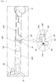
FIG. 1 is a perspective view of a folding personal mobility vehicle according to an exemplary embodiment of the present invention. -
FIG. 2 is a view for explaining a foothold part and a foothold locking mechanism ofFIG. 1 . -
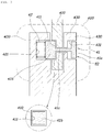
FIG. 3 is a view for explaining a hinge locking mechanism of a folding personal mobility vehicle according to an exemplary embodiment of the present invention. -
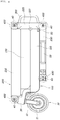
FIG. 4 is a view for explaining a folded state of the folding personal mobility vehicle according to the exemplary embodiment of the present invention. -
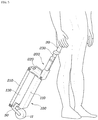
FIG. 5 is a view showing an example in which the personal mobility vehicle in the folded state is dragged. -
FIG. 6 is an example in which the personal mobility vehicle in the folded state is carried. - Hereinafter, a folding personal mobility vehicle according to an exemplary embodiment of the present invention will be described with reference to the accompanying drawings.
- Referring to
FIGS. 1 to 6 , folding personal mobility vehicle according to an exemplary embodiment of the present invention includes: afoothold part 100 provided with awheel 10 and having afront foothold part 110 and arear foothold part 120, with thefront foothold part 110 and therear foothold part 120 being connected to each other by a hinge structure to be folded against each other; and ahandle part 200 provided with ahandle 20 and folded by the hinge structure, in which therear foothold part 130 is folded on thefront foothold part 110 by the hinge structure and thehandle part 200 is folded on therear foothold part 130 by the hinge structure, such that therear foothold part 130 is positioned between thehandle part 200 and thefront foothold part 110 while being the folded. - In the state in which the
rear foothold part 130 is folded to be positioned between thehandle part 200 and thefront foothold part 110, thehandle part 200 and therear foothold part 130, and therear foothold part 130 and thefront foothold part 110 are stacked side by side and adhere to each other to prevent an empty space from being formed. That is, in the state in which therear foothold part 130 is folded to be positioned between thehandle part 200 and thefront foothold part 110, thehandle 20 is folded to adhere to a side of thehandle part 200 - Describing in more detail to the exemplary embodiment of the present invention, the folding personal mobility vehicle includes: a
foothold part 100 having thefront foothold part 110 whose front portion is provided with thewheel carrier 30 provided with afront wheel 11 and therear foothold part 130 whose rear portion is provided with arear wheel 12, thefront foothold part 110 and therear foothold part 130 being rotatably coupled to each other with respect to ahinge shaft 120; and thehandle part 200 provided with thehandle 20 and coupled to thewheel carrier 30 by ahinge locking mechanism 40, in which therear foothold part 130 rotates with respect to thehinge shaft 120 to be folded on thefront foothold part 110 and thehandle part 200 rotates with respect to thehinge locking mechanism 40 to be folded on therear foothold part 130, such that therear foothold part 130 is positioned between thehandle part 200 and thefront foothold part 110 while being folded. - The
handle part 200 includes alower handle part 210 coupled to thewheel carrier 30 by thehinge locking mechanism 40, amiddle handle part 220 coupled to thelower handle part 210 by thehinge locking mechanism 40, and anupper handle part 230 coupled to themiddle handle part 220 by thehinge locking mechanism 40, in which therear foothold part 130 is folded on thefront foothold part 110, thelower handle part 210 is folded on the rear foothold part 310, and themiddle handle part 220 is folded to be positioned at a rear of thefront foothold part 110 and therear foothold part 130, and theupper handle part 230 is folded on a lower portion of thefront foothold part 110. - The
handle 20 is provided on both sides of theupper handle part 230 by thehinge locking mechanism 40. Thehandle 20 is folded on both sides of theupper handle part 230. - Further, the folding personal mobility vehicle according to an exemplary embodiment of the present invention further includes a
foothold locking mechanism 50 provided on thefoothold part 100 to fix the unfolded state of thefront foothold part 110 and therear foothold part 130 and has a structure in which themiddle handle part 220 is coupled with acarrying handle 300. Thecarrying handle 300 protrudes rearward outward while being folded so that themiddle handle part 220 is positioned at the rear of thefront foothold part 110 and therear foothold part 130. - A
wheel groove 111 opened upward is formed at the front of thefront foothold part 110 and thewheel groove 111 is inserted with therear wheel 12 when therear foothold part 130 is folded so that therear foothold part 130 adheres to thefront foothold part 110. - The folding personal mobility vehicle according to the exemplary embodiment of the present invention has a structure in which the folding personal mobility vehicle may be in the unfolded state (used state) as illustrated in
FIG. 1 and may be in the folded state (carried and stored state) as illustrated inFIG. 4 . In the state in which the folding personal mobility vehicle is unfolded as illustrated inFIG. 1 , if therear foothold part 130 is folded to adhere to thefront foothold part 110, thelower handle part 210 is folded to adhere to therear foothold part 130, themiddle handle part 220 is folded to be positioned at one side of thefront foothold part 110 and one side of therear foothold part 130, theupper handle part 230 is folded to adhere to a bottom surface of thefront foothold part 110, and thehandle 20 is folded to adhere to both side surfaces of theupper handle part 230, the folding personal mobility vehicle is in an overlapping state by being completely folded as illustrated inFIG. 6 , and in the state in which the folding personal mobility vehicle is folded as illustrated inFIG. 6 , thelower handle part 210 and therear foothold part 130 completely adhere to each other, therear foothold part 130 and thefront foothold part 110 completely adhere to each other, and thefront foothold part 110 and theupper handle part 230 completely adhere to each other to prevent an empty space from being present between thelower handle part 210 and therear foothold part 130, between therear foothold part 130 and thefront foothold part 110, and between thefront foothold part 110 and theupper handle part 230 to minimize the volume of the folded state, such that the folding personal mobility vehicle may be effectively stored even in the narrow space and easily carried. - The
lower handle part 210 and themiddle handle part 220 and theupper handle part 230 and thehandle 20 that are in the folded state as described above are each maintained in a folded state by thehinge locking mechanism 40. Thehandle part 200 is connected to thewheel carrier 30 by thehinge part 400. Thehinge part 400 has aleft flange 420 and aright flange 430 provided at left and right sides thereof, with aninner flange 410 interposed therebetween. Theleft flange 420 and theright flange 430 are connected to each other and are separated from theinner flange 410. The overlapping portion of theinner flange 410 and theleft flange 420 and theright flange 430 are provided with thehinge locking mechanism 40. - That is, an upper end of the
wheel carrier 30 and a lower end of thelower handle part 210, an upper end of thelower handle part 210 and a lower end of themiddle handle part 220, an upper end of themiddle handle part 220 and a lower end of theupper handle part 230, and an upper end of theupper handle part 230 and one end of thehandle 20 each are ahinge part 400 that may implement the folding operation and the unfolding operation of thehandle part 200, thehinge part 400 is configured so that aleft flange 420 and aright flange 430 overlap with each other at left and right sides, having aninner flange 410 disposed therebetween, theleft flange 420 and theright flange 430 are configured to be separated from theinner flange 410 while having an integrated structure in which they are connected to each other like a yoke shape, and thehinge locking mechanism 40 is installed at a part where theinner flange 410, theleft flange 420, and theright flange 430 overlap with each other. - The
hinge locking mechanism 40 includes alocking pin 41 having apressing part 41a of one end and alocking part 41b of the other end and arod part 41c connecting between thepressing part 41a and thelocking part 41b and alocking spring 42 for elastically supporting thelocking part 41b of thelocking pin 41. - The
pressing part 41a is installed to be movable along a longitudinal direction of therod part 41c while being inserted into anoperating groove 431 formed at theright flange 430, thelocking part 41b is installed to be separated from thelocking groove 411 at the time of pressing thepressing part 41a while being installed to be simultaneously inserted into thelocking groove 411 formed at theinner flange 410 and arelease groove 421 formed at theleft flange 420, and therod part 41c is installed to connect between thepressing part 41a and thelocking part 41b by penetrating through theright flange 430 and theinner flange 410. - The
locking spring 42 has one end supported to thelocking part 41b and the other end supported into therelease groove 421 and thus is a compression spring for pressing thelocking part 41b toward thepressing part 41a by the accumulated elastic force. - If a user presses the
pressing part 41a and thus thelocking part 41b is separated from thelocking groove 411, theinner flange 410 and theleft flange 420 and theright flange 430 may relatively rotate with respect to therod part 41c. In this case, the folding operation of thehandle part 200 may be implemented by the relative rotation between theinner flange 410 and theleft flange 420 and theright flange 430. - Meanwhile, the
locking part 41b and thelocking groove 411 have an outer circumference having a quadrangular cross section and thus thelocking part 41b rotates by 90° when theinner flange 410 and theleft flange 420 and theright flange 430 relatively rotate with respect to therod part 41c and then are maintained in the locked state again, that is, thelocking part 41b rotates by 90° in the state in which it is released from thelocking groove 411 and then thelocking part 41b is inserted into thelocking groove 411 again, such that they may be maintained in the locked state again. - A rear upper edge part of the
front foothold part 110 and a front upper edge part of therear foothold part 130 are rotatably coupled with each other via thehinge shaft 120 while overlapping with each other and thefoothold locking mechanism 50 is installed under thehinge shaft 120. - The
foothold locking mechanism 50 includes a lockinglever 52 rotatably installed at a rear lower edge part of thefront foothold part 110 via alever shaft 51, alocking protruding groove 53 formed at a front lower edge part of therear foothold part 130 so that a lockingprotrusion 52a formed at one end of the lockinglever 52 is inserted into thelocking protruding groove 53 and locked, and alever spring 54 having one end fixed to thefront foothold part 110 and the other end fixed to thelever shaft 52 while being wound around thelever shaft 52 and applying an elastic force so that the lockinglever 52 may rotate in a direction in which the lockingprotrusion 52a is inserted into thelocking protruding groove 53, such that thelever spring 54 is the torsion spring. - Therefore, as illustrated in
FIG. 2 , even if the user boards thefoothold part 100 in the state in which thefront foothold part 110 and therear foothold part 130 are coupled with each other by thefoothold locking mechanism 50 in the state in which thefront foothold part 110 and therear foothold part 130 are unfolded straightly, thefront foothold part 110 and therear foothold part 130 are kept on being unfolded straightly by the adhesion of thefoothold locking mechanism 50. - Further, after the user releases the locking of the
foothold locking mechanism 50, therear foothold part 130 rotates upward with respect to thehinge shaft 120 so that therear foothold part 130 adheres to thefront foothold part 110. In this case, thefoothold part 100 is folded as therear wheel 12 is inserted into thewheel groove 111. - In the folding personal mobility vehicle according to the exemplary embodiment of the present invention, as illustrated in
FIG. 5 , when therear foothold part 130 is folded to adhere to thefront foothold part 110, thelower handle part 210 is folded to adhere to therear foothold part 130, themiddle handle part 220 is folded to be positioned at one side of thefront foothold part 110 and therear foothold part 130, and theupper handle part 230 is unfolded to extend along the longitudinal direction of thefront foothold part 110, the user holds thehandle 20 to bring thefront wheel 11 into contact with a ground surface and then drag the folding personal mobility vehicle. - Further, as illustrated in
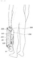
FIG. 6 , when thelower handle part 210 is folded to adhere to therear foothold part 130, themiddle handle part 220 is folded to be positioned at one side of thefront foothold part 110 and therear foothold part 130, theupper handle part 230 is folded to adhere to the bottom surface of thefront foothold part 110, thehandle 20 is in the overlapping state by being completely folded to adhere to both side surfaces of theupper handle part 230, the user uses a carryinghandle 300 provided at themiddle handle part 220 to carry the folding personal mobility vehicle or store it in a luggage room or a trunk room of the vehicle. On the other hand, theupper handle part 230 is unfolded to extend in a longitudinal direction of thefront foothold part 110 while not being folded downward of thefront foothold part 110. - As described above, the folding personal mobility vehicle according to the exemplary embodiment of the present invention including the
foothold part 100 provided with thewheel 10 and thehandle part 200 provided with thehandle 20 like a kick board may prevent the empty space from being present between thelower handle part 210 and therear foothold part 130, between therear foothold part 130 and thefront foothold part 110, and between thefront foothold part 110 and theupper handle part 230 when being completely folded for carrying and storage to minimize the volume of the completely folded state, such that the folding personal mobility vehicle may be effectively stored even in the narrow space and easily carried. - According to the exemplary embodiment of the present invention, the folding personal mobility vehicle that includes the foothold part provided with the wheel and the handle part provided with the handle may prevent the empty space from being present between the lower handle part and the rear foothold part, between the rear foothold part and the front foothold part, and between the front foothold part and the upper handle part when being completely folded for carrying or storage to minimize the volume of the completely folded state, such that the folding personal mobility vehicle may be effectively stored even in the narrow space and easily carried.
- Although the present invention has been shown and described with respect to specific exemplary embodiments, it will be obvious to those skilled in the art that the present invention may be variously modified and altered without departing from the spirit and scope of the present invention as defined by the following claims.
Claims (18)
- A folding personal mobility comprising:a foothold part provided with a wheel and having a front foothold part and a rear foothold part, with the front foothold part and the rear foothold part being connected to each other by a hinge structure to be folded against each other;and a handle part provided with a handle and foldable by the hinge structure,wherein the rear foothold part is folded on the front foothold part by the hinge structure and the handle part is folded on the rear foothold part by the hinge structure, such that the rear foothold part is positioned between the handle part and the front foothold part while being folded.
- The folding personal mobility of claim 1, wherein in the state in which the rear foothold part is folded to be positioned between the handle part and the front foothold part, the handle part and the rear foothold part, and the rear foothold part and the front foothold part are stacked side by side and adjacent to each other.
- The folding personal mobility of claim 1, wherein in the state in which the rear foothold part is folded to be positioned between the handle part and the front foothold part, the handle is folded to adhere to a side of the handle part.
- A folding personal mobility comprising:a foothold part having a front foothold part whose front portion is provided with a wheel carrier provided with a front wheel and a rear foothold part whose rear portion is provided with a rear wheel, the front foothold part and the rear foothold part being rotatably coupled to each other with respect to a hinge shaft; anda handle part provided with a handle and coupled to the wheel carrier by a hinge locking mechanism;wherein the rear foothold part rotates with respect to the hinge shaft to be folded on the front foothold part and the handle part rotates with respect to the hinge locking mechanism to be folded on the rear foothold part, such that the rear foothold part is positioned between the handle part and the front foothold part while being folded.
- The folding personal mobility of claim 4, further comprising: a foothold locking mechanism provided on the foothold part to fix an unfolded state of the front foothold part and the rear foothold part.
- The folding personal mobility of claim 4, wherein the handle part includes a lower handle part coupled with the wheel carrier by a hinge locking mechanism, a middle handle part coupled with the lower handle part by the hinge locking mechanism, and an upper handle part coupled with the middle handle part by the hinge locking mechanism, and
the rear foothold part is folded on the front foothold part, the lower handle part is folded on the rear foothold part, and the middle handle part is folded to be positioned at a rear of the front foothold part and the rear foothold part, and the upper handle part is folded on a lower portion of the front foothold part. - The folding personal mobility of claim 4, wherein the middle handle part is provided with a carrying handle, and the carrying handle protrudes rearward outward while being folded so that the middle handle part is positioned at positioned at the rear of the front foothold part and the rear foothold part.
- The folding personal mobility of claim 4, wherein an upper front of the front foothold part is provided with a wheel groove into which the rear wheel is inserted when the rear foothold part is folded on the front foothold part.
- The folding personal mobility of claim 4, wherein the upper handle part is coupled to the handle by the hinge locking mechanism and the handle is folded on both sides of the upper handle part.
- The folding personal mobility of claim 9, wherein the lower handle part, the middle handle part, the upper handle part, and the handles are maintained in the folded state by the hinge locking mechanism.
- The folding personal mobility of claim 4, wherein the handle part is connected to the wheel carrier by a hinge part, the hinge part has a left flange and a right flange provided at left and right sides thereof, with an inner flange interposed therebetween, the left flange and the right flange are connected to each other and are separated from the inner flange, and an overlapping portion of the inner flange and the left flange and the right flange are provided with the hinge locking mechanism.
- The folding personal mobility of claim 10, wherein the lower handle part, the middle handle part, the upper handle part, and the handle are provided with a hinge part, and the hinge part has a left flange and a right flange provided at left and right sides thereof, with an inner flange interposed therebetween, the left flange and the right flange are connected to each other and are separated from the inner flange, and an overlapping portion of the inner flange and the left flange and the right flange are provided with the hinge locking mechanism.
- The folding personal mobility of claim 11, wherein the hinge locking mechanism includes a locking pin having a pressing part of one end and a locking part of the other end and a rod part connecting between the pressing part and the locking part and a locking spring for elastically supporting the locking part of the locking pin, the pressing part is installed to be movable along a longitudinal direction of the rod part while being inserted into an operating groove formed at the right flange, the locking part is installed to be separated from a locking groove at the time of pressing the pressing part while being installed to be simultaneously inserted into the locking groove formed at the inner flange and a release groove formed at the left flange, the rod part is installed to connect between the pressing part and the locking part by penetrating through the right flange and the inner flange, and the locking spring has one end supported to the locking part and the other end supported into the release groove and thus presses the locking part toward the pressing part by the accumulated elastic force.
- The folding personal mobility of claim 13, wherein if a user presses the pressing part and thus the locking part is separated from the locking groove, the left flange and the right flange relatively rotate with respect to the inner flange based on the rod part, and the folding operation of the handle part is enabled by the relative rotation of the left flange and the right flange.
- The folding personal mobility of claim 13, wherein an outer circumference of the locking part and the locking groove has a rectangular cross section, such that the left flange and the right flange maintain a locked state after rotating by 90° when relatively rotating with respect to the inner flange based on the rod part.
- The folding personal mobility of claim 5, wherein a rear upper edge part of the front foothold part and a front upper edge part of the rear foothold part are rotatably coupled with each other with respect to the hinge shaft while overlapping with each other.
- The folding personal mobility of claim 16, wherein a foothold locking mechanism includes a locking lever rotatably installed at a rear lower edge part of the front foothold part via a lever shaft, a locking protruding groove formed at a front lower edge part of the rear foothold part so that a locking protrusion formed at one end of the locking lever is inserted into the locking protruding groove and locked, and a lever spring having one end fixed to the front foothold part and the other end fixed to the lever shaft while being wound around the lever shaft and applying an elastic force so that the locking lever rotates in a direction in which the locking protrusion is inserted into the locking protruding groove.
- The folding personal mobility of claim 6, wherein the upper handle part is unfolded to extend in a longitudinal direction of the front foothold part while not being folded downward of the front foothold part.
Applications Claiming Priority (1)
| Application Number | Priority Date | Filing Date | Title |
|---|---|---|---|
| KR1020160172246A KR101918368B1 (en) | 2016-12-16 | 2016-12-16 | Folding personal mobility |
Publications (2)
| Publication Number | Publication Date |
|---|---|
| EP3335970A1 true EP3335970A1 (en) | 2018-06-20 |
| EP3335970B1 EP3335970B1 (en) | 2019-08-21 |
Family
ID=60661760
Family Applications (1)
| Application Number | Title | Priority Date | Filing Date |
|---|---|---|---|
| EP17205317.5A Active EP3335970B1 (en) | 2016-12-16 | 2017-12-05 | Folding personal mobility vehicle |
Country Status (6)
| Country | Link |
|---|---|
| US (1) | US10328986B2 (en) |
| EP (1) | EP3335970B1 (en) |
| KR (1) | KR101918368B1 (en) |
| CN (2) | CN207644546U (en) |
| DE (1) | DE102017214951A1 (en) |
| ES (1) | ES2745898T3 (en) |
Cited By (1)
| Publication number | Priority date | Publication date | Assignee | Title |
|---|---|---|---|---|
| FR3101604A1 (en) * | 2019-10-07 | 2021-04-09 | Celerifere Sas | FOLDABLE SCOOTER |
Families Citing this family (19)
| Publication number | Priority date | Publication date | Assignee | Title |
|---|---|---|---|---|
| KR101918368B1 (en) * | 2016-12-16 | 2018-11-13 | 현대자동차주식회사 | Folding personal mobility |
| WO2020033599A1 (en) * | 2018-08-07 | 2020-02-13 | Trio Motors, Inc. | Tri-mode collapsible scooter |
| US11345429B2 (en) * | 2018-08-07 | 2022-05-31 | Trio Motors, Inc. | Articulating, self-centering truck for personal mobility vehicles |
| JP6837463B2 (en) * | 2018-11-22 | 2021-03-03 | 本田技研工業株式会社 | Saddle-type vehicle |
| GB2581787B (en) * | 2019-02-22 | 2021-12-29 | Aer Electric Company Ltd | A foldable scooter |
| KR102541038B1 (en) * | 2019-04-17 | 2023-06-08 | 현대자동차주식회사 | Folding structure of personal mobility device and personal mobility device including the same |
| KR102079902B1 (en) * | 2019-08-30 | 2020-04-07 | (주)크로스오버존 | Foldable electric kick board |
| CN111661216A (en) * | 2020-06-19 | 2020-09-15 | 王尼甫 | An intelligent sports and leisure folding scooter |
| CN111907633A (en) * | 2020-07-09 | 2020-11-10 | 刘思尧 | Folding electric scooter |
| CN111891281B (en) * | 2020-08-07 | 2024-12-27 | 广州宝乐实业发展有限公司 | Four-link efficient folding structure and folding scooter |
| KR102585658B1 (en) * | 2021-08-20 | 2023-10-10 | 주식회사 서진오토모티브 | Foldable structure of electric kickboard with excellent portability |
| KR102534254B1 (en) * | 2021-12-10 | 2023-05-26 | (주)씨에스이 | Multi-stage folding kickboard |
| CN114132420A (en) * | 2022-01-06 | 2022-03-04 | 吴剑斌 | A folding electric vehicle |
| KR102575758B1 (en) | 2022-02-25 | 2023-09-06 | 주식회사 라오닉스 | Folding last-mile mobility |
| CN114670964A (en) * | 2022-03-29 | 2022-06-28 | 杭州久高科技有限公司 | A portable folding vehicle |
| KR20240054688A (en) | 2022-10-19 | 2024-04-26 | 주식회사 라오닉스 | Folding last-mile mobility |
| US12397873B2 (en) * | 2022-10-25 | 2025-08-26 | Anita Wu | Foldable scooter |
| CN116022277B (en) * | 2023-02-06 | 2025-08-29 | 深圳市爱斯特高新科技有限公司 | A folding scooter |
| TW202542038A (en) * | 2024-04-15 | 2025-11-01 | 江尚峰 | Folding mechanism and frame with folding mechanism |
Citations (4)
| Publication number | Priority date | Publication date | Assignee | Title |
|---|---|---|---|---|
| DE10045821A1 (en) * | 2000-09-15 | 2002-03-28 | Harald Kutzke | Folding scooter has tread-plate, links, rocker arms as mountings for front and rear wheels, steering-head or tube, and handles. |
| US20100044137A1 (en) * | 2006-05-08 | 2010-02-25 | Lakehead University | Powered foldable scooter |
| EP2780219A1 (en) * | 2010-12-02 | 2014-09-24 | Jacques Benarrouch | Three-part foldable scooter having retractable wheels |
| CN104743033A (en) * | 2015-04-17 | 2015-07-01 | 胡振宇 | Novel foldable scooter and use method thereof |
Family Cites Families (11)
| Publication number | Priority date | Publication date | Assignee | Title |
|---|---|---|---|---|
| GB0809278D0 (en) * | 2008-05-22 | 2008-06-25 | Re Creation Group Plc | Scooter and method of use thereof |
| WO2010140143A1 (en) * | 2009-06-02 | 2010-12-09 | Riccardo Nimrod Sapir | Folding wheel mechanism for vehicle |
| KR101152580B1 (en) * | 2010-06-30 | 2012-06-01 | 삼성모바일디스플레이주식회사 | Pixel and Organic Light Emitting Display Device Using the Same |
| US8487489B2 (en) * | 2010-07-30 | 2013-07-16 | General Electric Company | Apparatus for cooling an electric machine |
| NL2008301C2 (en) * | 2012-02-16 | 2013-08-19 | Leev Mobility B V | Foldable scooter. |
| CN203032849U (en) * | 2012-10-29 | 2013-07-03 | 吴结华 | Portable reverse-three-wheel rapid-folding electric vehicle |
| US20150008431A1 (en) * | 2013-07-04 | 2015-01-08 | Nanya Technology Corporation | Method and layout for detecting die cracks |
| KR20160033582A (en) * | 2014-09-18 | 2016-03-28 | 고영승 | Foldable Kick Board |
| US9718512B2 (en) * | 2015-09-14 | 2017-08-01 | Chengzhai Mei | Foldable scooter and method of folding same |
| CN106564550B (en) * | 2016-10-27 | 2020-01-14 | 芦慧 | Foldable personal vehicle |
| KR101918368B1 (en) * | 2016-12-16 | 2018-11-13 | 현대자동차주식회사 | Folding personal mobility |
-
2016
- 2016-12-16 KR KR1020160172246A patent/KR101918368B1/en active Active
-
2017
- 2017-07-07 US US15/643,689 patent/US10328986B2/en active Active
- 2017-08-28 DE DE102017214951.5A patent/DE102017214951A1/en not_active Withdrawn
- 2017-12-05 EP EP17205317.5A patent/EP3335970B1/en active Active
- 2017-12-05 ES ES17205317T patent/ES2745898T3/en active Active
- 2017-12-07 CN CN201721691910.4U patent/CN207644546U/en active Active
- 2017-12-07 CN CN201711286340.5A patent/CN108202810B/en active Active
Patent Citations (4)
| Publication number | Priority date | Publication date | Assignee | Title |
|---|---|---|---|---|
| DE10045821A1 (en) * | 2000-09-15 | 2002-03-28 | Harald Kutzke | Folding scooter has tread-plate, links, rocker arms as mountings for front and rear wheels, steering-head or tube, and handles. |
| US20100044137A1 (en) * | 2006-05-08 | 2010-02-25 | Lakehead University | Powered foldable scooter |
| EP2780219A1 (en) * | 2010-12-02 | 2014-09-24 | Jacques Benarrouch | Three-part foldable scooter having retractable wheels |
| CN104743033A (en) * | 2015-04-17 | 2015-07-01 | 胡振宇 | Novel foldable scooter and use method thereof |
Cited By (1)
| Publication number | Priority date | Publication date | Assignee | Title |
|---|---|---|---|---|
| FR3101604A1 (en) * | 2019-10-07 | 2021-04-09 | Celerifere Sas | FOLDABLE SCOOTER |
Also Published As
| Publication number | Publication date |
|---|---|
| KR101918368B1 (en) | 2018-11-13 |
| US20180170473A1 (en) | 2018-06-21 |
| KR20180001995A (en) | 2018-01-05 |
| CN207644546U (en) | 2018-07-24 |
| DE102017214951A1 (en) | 2018-06-21 |
| EP3335970B1 (en) | 2019-08-21 |
| US10328986B2 (en) | 2019-06-25 |
| CN108202810A (en) | 2018-06-26 |
| ES2745898T3 (en) | 2020-03-04 |
| CN108202810B (en) | 2021-05-28 |
Similar Documents
| Publication | Publication Date | Title |
|---|---|---|
| EP3335970A1 (en) | Folding personal mobility vehicle | |
| US10589771B2 (en) | Cart with wheel that is easily lockable and unlockable | |
| CN111746605B (en) | Folding four-wheel flat car | |
| US8857299B2 (en) | Hand tool | |
| CN111376958B (en) | Folding pull-rod vehicle | |
| US7311323B1 (en) | Stroller having a foldable handle frame capable of being automatically locked in a folded state | |
| US9475516B1 (en) | Folding device for baby carriage | |
| US9718512B2 (en) | Foldable scooter and method of folding same | |
| US20060226617A1 (en) | Easily detached and assembled golf cart with auxiliary wheel | |
| US20060273553A1 (en) | Foldable stroller with a control cable operable to allow for folding of the stroller | |
| US20080174081A1 (en) | Pushcart | |
| WO2016045507A1 (en) | Steering system and folding vehicle | |
| CN101736938A (en) | Cargo floor handle | |
| CN202681052U (en) | Foldable trolley | |
| US8844402B2 (en) | Crank handle apparatus with fold-away handle | |
| CN102616326A (en) | Handle folding mechanism | |
| TW201233582A (en) | Foldable scooter and operation method thereof | |
| CN207208328U (en) | A kind of fold mechanism of scooter footboard | |
| EP2868558A1 (en) | Concealed folding mechanism for a kick scooter | |
| CN203901303U (en) | Jackknife capable of popping up after being unlocked | |
| CN103419822B (en) | A kind of folded bicycle | |
| KR100692237B1 (en) | Folding tail boom | |
| CN206155693U (en) | Folding scooter | |
| CN104627295A (en) | Hidden folding mechanism for scooter | |
| CN202557585U (en) | Foldable trolley |
Legal Events
| Date | Code | Title | Description |
|---|---|---|---|
| PUAI | Public reference made under article 153(3) epc to a published international application that has entered the european phase |
Free format text: ORIGINAL CODE: 0009012 |
|
| STAA | Information on the status of an ep patent application or granted ep patent |
Free format text: STATUS: THE APPLICATION HAS BEEN PUBLISHED |
|
| AK | Designated contracting states |
Kind code of ref document: A1 Designated state(s): AL AT BE BG CH CY CZ DE DK EE ES FI FR GB GR HR HU IE IS IT LI LT LU LV MC MK MT NL NO PL PT RO RS SE SI SK SM TR |
|
| AX | Request for extension of the european patent |
Extension state: BA ME |
|
| STAA | Information on the status of an ep patent application or granted ep patent |
Free format text: STATUS: REQUEST FOR EXAMINATION WAS MADE |
|
| 17P | Request for examination filed |
Effective date: 20181206 |
|
| RBV | Designated contracting states (corrected) |
Designated state(s): AL AT BE BG CH CY CZ DE DK EE ES FI FR GB GR HR HU IE IS IT LI LT LU LV MC MK MT NL NO PL PT RO RS SE SI SK SM TR |
|
| RIC1 | Information provided on ipc code assigned before grant |
Ipc: B62K 15/00 20060101ALI20190221BHEP Ipc: B62K 3/00 20060101AFI20190221BHEP |
|
| GRAP | Despatch of communication of intention to grant a patent |
Free format text: ORIGINAL CODE: EPIDOSNIGR1 |
|
| STAA | Information on the status of an ep patent application or granted ep patent |
Free format text: STATUS: GRANT OF PATENT IS INTENDED |
|
| INTG | Intention to grant announced |
Effective date: 20190403 |
|
| GRAS | Grant fee paid |
Free format text: ORIGINAL CODE: EPIDOSNIGR3 |
|
| GRAA | (expected) grant |
Free format text: ORIGINAL CODE: 0009210 |
|
| STAA | Information on the status of an ep patent application or granted ep patent |
Free format text: STATUS: THE PATENT HAS BEEN GRANTED |
|
| AK | Designated contracting states |
Kind code of ref document: B1 Designated state(s): AL AT BE BG CH CY CZ DE DK EE ES FI FR GB GR HR HU IE IS IT LI LT LU LV MC MK MT NL NO PL PT RO RS SE SI SK SM TR |
|
| REG | Reference to a national code |
Ref country code: GB Ref legal event code: FG4D |
|
| REG | Reference to a national code |
Ref country code: CH Ref legal event code: EP |
|
| REG | Reference to a national code |
Ref country code: DE Ref legal event code: R096 Ref document number: 602017006347 Country of ref document: DE |
|
| REG | Reference to a national code |
Ref country code: AT Ref legal event code: REF Ref document number: 1169427 Country of ref document: AT Kind code of ref document: T Effective date: 20190915 |
|
| REG | Reference to a national code |
Ref country code: IE Ref legal event code: FG4D |
|
| REG | Reference to a national code |
Ref country code: NL Ref legal event code: FP |
|
| REG | Reference to a national code |
Ref country code: SE Ref legal event code: TRGR |
|
| REG | Reference to a national code |
Ref country code: NO Ref legal event code: T2 Effective date: 20190821 |
|
| REG | Reference to a national code |
Ref country code: LT Ref legal event code: MG4D |
|
| PG25 | Lapsed in a contracting state [announced via postgrant information from national office to epo] |
Ref country code: BG Free format text: LAPSE BECAUSE OF FAILURE TO SUBMIT A TRANSLATION OF THE DESCRIPTION OR TO PAY THE FEE WITHIN THE PRESCRIBED TIME-LIMIT Effective date: 20191121 Ref country code: FI Free format text: LAPSE BECAUSE OF FAILURE TO SUBMIT A TRANSLATION OF THE DESCRIPTION OR TO PAY THE FEE WITHIN THE PRESCRIBED TIME-LIMIT Effective date: 20190821 Ref country code: LT Free format text: LAPSE BECAUSE OF FAILURE TO SUBMIT A TRANSLATION OF THE DESCRIPTION OR TO PAY THE FEE WITHIN THE PRESCRIBED TIME-LIMIT Effective date: 20190821 Ref country code: PT Free format text: LAPSE BECAUSE OF FAILURE TO SUBMIT A TRANSLATION OF THE DESCRIPTION OR TO PAY THE FEE WITHIN THE PRESCRIBED TIME-LIMIT Effective date: 20191223 Ref country code: HR Free format text: LAPSE BECAUSE OF FAILURE TO SUBMIT A TRANSLATION OF THE DESCRIPTION OR TO PAY THE FEE WITHIN THE PRESCRIBED TIME-LIMIT Effective date: 20190821 |
|
| PG25 | Lapsed in a contracting state [announced via postgrant information from national office to epo] |
Ref country code: AL Free format text: LAPSE BECAUSE OF FAILURE TO SUBMIT A TRANSLATION OF THE DESCRIPTION OR TO PAY THE FEE WITHIN THE PRESCRIBED TIME-LIMIT Effective date: 20190821 Ref country code: GR Free format text: LAPSE BECAUSE OF FAILURE TO SUBMIT A TRANSLATION OF THE DESCRIPTION OR TO PAY THE FEE WITHIN THE PRESCRIBED TIME-LIMIT Effective date: 20191122 Ref country code: RS Free format text: LAPSE BECAUSE OF FAILURE TO SUBMIT A TRANSLATION OF THE DESCRIPTION OR TO PAY THE FEE WITHIN THE PRESCRIBED TIME-LIMIT Effective date: 20190821 Ref country code: IS Free format text: LAPSE BECAUSE OF FAILURE TO SUBMIT A TRANSLATION OF THE DESCRIPTION OR TO PAY THE FEE WITHIN THE PRESCRIBED TIME-LIMIT Effective date: 20191221 Ref country code: LV Free format text: LAPSE BECAUSE OF FAILURE TO SUBMIT A TRANSLATION OF THE DESCRIPTION OR TO PAY THE FEE WITHIN THE PRESCRIBED TIME-LIMIT Effective date: 20190821 |
|
| REG | Reference to a national code |
Ref country code: ES Ref legal event code: FG2A Ref document number: 2745898 Country of ref document: ES Kind code of ref document: T3 Effective date: 20200304 |
|
| REG | Reference to a national code |
Ref country code: AT Ref legal event code: MK05 Ref document number: 1169427 Country of ref document: AT Kind code of ref document: T Effective date: 20190821 |
|
| PG25 | Lapsed in a contracting state [announced via postgrant information from national office to epo] |
Ref country code: TR Free format text: LAPSE BECAUSE OF FAILURE TO SUBMIT A TRANSLATION OF THE DESCRIPTION OR TO PAY THE FEE WITHIN THE PRESCRIBED TIME-LIMIT Effective date: 20190821 |
|
| PG25 | Lapsed in a contracting state [announced via postgrant information from national office to epo] |
Ref country code: RO Free format text: LAPSE BECAUSE OF FAILURE TO SUBMIT A TRANSLATION OF THE DESCRIPTION OR TO PAY THE FEE WITHIN THE PRESCRIBED TIME-LIMIT Effective date: 20190821 Ref country code: AT Free format text: LAPSE BECAUSE OF FAILURE TO SUBMIT A TRANSLATION OF THE DESCRIPTION OR TO PAY THE FEE WITHIN THE PRESCRIBED TIME-LIMIT Effective date: 20190821 Ref country code: DK Free format text: LAPSE BECAUSE OF FAILURE TO SUBMIT A TRANSLATION OF THE DESCRIPTION OR TO PAY THE FEE WITHIN THE PRESCRIBED TIME-LIMIT Effective date: 20190821 Ref country code: PL Free format text: LAPSE BECAUSE OF FAILURE TO SUBMIT A TRANSLATION OF THE DESCRIPTION OR TO PAY THE FEE WITHIN THE PRESCRIBED TIME-LIMIT Effective date: 20190821 Ref country code: EE Free format text: LAPSE BECAUSE OF FAILURE TO SUBMIT A TRANSLATION OF THE DESCRIPTION OR TO PAY THE FEE WITHIN THE PRESCRIBED TIME-LIMIT Effective date: 20190821 |
|
| PG25 | Lapsed in a contracting state [announced via postgrant information from national office to epo] |
Ref country code: CZ Free format text: LAPSE BECAUSE OF FAILURE TO SUBMIT A TRANSLATION OF THE DESCRIPTION OR TO PAY THE FEE WITHIN THE PRESCRIBED TIME-LIMIT Effective date: 20190821 Ref country code: IS Free format text: LAPSE BECAUSE OF FAILURE TO SUBMIT A TRANSLATION OF THE DESCRIPTION OR TO PAY THE FEE WITHIN THE PRESCRIBED TIME-LIMIT Effective date: 20200224 Ref country code: SM Free format text: LAPSE BECAUSE OF FAILURE TO SUBMIT A TRANSLATION OF THE DESCRIPTION OR TO PAY THE FEE WITHIN THE PRESCRIBED TIME-LIMIT Effective date: 20190821 Ref country code: SK Free format text: LAPSE BECAUSE OF FAILURE TO SUBMIT A TRANSLATION OF THE DESCRIPTION OR TO PAY THE FEE WITHIN THE PRESCRIBED TIME-LIMIT Effective date: 20190821 |
|
| REG | Reference to a national code |
Ref country code: DE Ref legal event code: R097 Ref document number: 602017006347 Country of ref document: DE |
|
| PLBE | No opposition filed within time limit |
Free format text: ORIGINAL CODE: 0009261 |
|
| STAA | Information on the status of an ep patent application or granted ep patent |
Free format text: STATUS: NO OPPOSITION FILED WITHIN TIME LIMIT |
|
| PG2D | Information on lapse in contracting state deleted |
Ref country code: IS |
|
| 26N | No opposition filed |
Effective date: 20200603 |
|
| REG | Reference to a national code |
Ref country code: BE Ref legal event code: MM Effective date: 20191231 |
|
| PG25 | Lapsed in a contracting state [announced via postgrant information from national office to epo] |
Ref country code: SI Free format text: LAPSE BECAUSE OF FAILURE TO SUBMIT A TRANSLATION OF THE DESCRIPTION OR TO PAY THE FEE WITHIN THE PRESCRIBED TIME-LIMIT Effective date: 20190821 Ref country code: MC Free format text: LAPSE BECAUSE OF FAILURE TO SUBMIT A TRANSLATION OF THE DESCRIPTION OR TO PAY THE FEE WITHIN THE PRESCRIBED TIME-LIMIT Effective date: 20190821 |
|
| PG25 | Lapsed in a contracting state [announced via postgrant information from national office to epo] |
Ref country code: LU Free format text: LAPSE BECAUSE OF NON-PAYMENT OF DUE FEES Effective date: 20191205 Ref country code: IE Free format text: LAPSE BECAUSE OF NON-PAYMENT OF DUE FEES Effective date: 20191205 |
|
| PG25 | Lapsed in a contracting state [announced via postgrant information from national office to epo] |
Ref country code: BE Free format text: LAPSE BECAUSE OF NON-PAYMENT OF DUE FEES Effective date: 20191231 |
|
| PG25 | Lapsed in a contracting state [announced via postgrant information from national office to epo] |
Ref country code: CY Free format text: LAPSE BECAUSE OF FAILURE TO SUBMIT A TRANSLATION OF THE DESCRIPTION OR TO PAY THE FEE WITHIN THE PRESCRIBED TIME-LIMIT Effective date: 20190821 |
|
| PG25 | Lapsed in a contracting state [announced via postgrant information from national office to epo] |
Ref country code: HU Free format text: LAPSE BECAUSE OF FAILURE TO SUBMIT A TRANSLATION OF THE DESCRIPTION OR TO PAY THE FEE WITHIN THE PRESCRIBED TIME-LIMIT; INVALID AB INITIO Effective date: 20171205 Ref country code: MT Free format text: LAPSE BECAUSE OF FAILURE TO SUBMIT A TRANSLATION OF THE DESCRIPTION OR TO PAY THE FEE WITHIN THE PRESCRIBED TIME-LIMIT Effective date: 20190821 |
|
| REG | Reference to a national code |
Ref country code: CH Ref legal event code: PL |
|
| PG25 | Lapsed in a contracting state [announced via postgrant information from national office to epo] |
Ref country code: LI Free format text: LAPSE BECAUSE OF NON-PAYMENT OF DUE FEES Effective date: 20201231 Ref country code: CH Free format text: LAPSE BECAUSE OF NON-PAYMENT OF DUE FEES Effective date: 20201231 |
|
| PG25 | Lapsed in a contracting state [announced via postgrant information from national office to epo] |
Ref country code: MK Free format text: LAPSE BECAUSE OF FAILURE TO SUBMIT A TRANSLATION OF THE DESCRIPTION OR TO PAY THE FEE WITHIN THE PRESCRIBED TIME-LIMIT Effective date: 20190821 |
|
| P01 | Opt-out of the competence of the unified patent court (upc) registered |
Effective date: 20230511 |
|
| PGFP | Annual fee paid to national office [announced via postgrant information from national office to epo] |
Ref country code: NL Payment date: 20241120 Year of fee payment: 8 |
|
| PGFP | Annual fee paid to national office [announced via postgrant information from national office to epo] |
Ref country code: NO Payment date: 20241122 Year of fee payment: 8 |
|
| PGFP | Annual fee paid to national office [announced via postgrant information from national office to epo] |
Ref country code: GB Payment date: 20241121 Year of fee payment: 8 |
|
| PGFP | Annual fee paid to national office [announced via postgrant information from national office to epo] |
Ref country code: FR Payment date: 20241121 Year of fee payment: 8 |
|
| PGFP | Annual fee paid to national office [announced via postgrant information from national office to epo] |
Ref country code: IT Payment date: 20241125 Year of fee payment: 8 |
|
| PGFP | Annual fee paid to national office [announced via postgrant information from national office to epo] |
Ref country code: SE Payment date: 20241121 Year of fee payment: 8 |
|
| PGFP | Annual fee paid to national office [announced via postgrant information from national office to epo] |
Ref country code: ES Payment date: 20250113 Year of fee payment: 8 |
|
| PGFP | Annual fee paid to national office [announced via postgrant information from national office to epo] |
Ref country code: DE Payment date: 20251120 Year of fee payment: 9 |