EP3335944A1 - Work vehicle - Google Patents
Work vehicle Download PDFInfo
- Publication number
- EP3335944A1 EP3335944A1 EP17000886.6A EP17000886A EP3335944A1 EP 3335944 A1 EP3335944 A1 EP 3335944A1 EP 17000886 A EP17000886 A EP 17000886A EP 3335944 A1 EP3335944 A1 EP 3335944A1
- Authority
- EP
- European Patent Office
- Prior art keywords
- peripheral
- synthesizing
- work
- vehicle body
- image
- Prior art date
- Legal status (The legal status is an assumption and is not a legal conclusion. Google has not performed a legal analysis and makes no representation as to the accuracy of the status listed.)
- Granted
Links
Images


Classifications
-
- H—ELECTRICITY
- H04—ELECTRIC COMMUNICATION TECHNIQUE
- H04N—PICTORIAL COMMUNICATION, e.g. TELEVISION
- H04N23/00—Cameras or camera modules comprising electronic image sensors; Control thereof
- H04N23/60—Control of cameras or camera modules
- H04N23/64—Computer-aided capture of images, e.g. transfer from script file into camera, check of taken image quality, advice or proposal for image composition or decision on when to take image
-
- B—PERFORMING OPERATIONS; TRANSPORTING
- B60—VEHICLES IN GENERAL
- B60R—VEHICLES, VEHICLE FITTINGS, OR VEHICLE PARTS, NOT OTHERWISE PROVIDED FOR
- B60R1/00—Optical viewing arrangements; Real-time viewing arrangements for drivers or passengers using optical image capturing systems, e.g. cameras or video systems specially adapted for use in or on vehicles
- B60R1/20—Real-time viewing arrangements for drivers or passengers using optical image capturing systems, e.g. cameras or video systems specially adapted for use in or on vehicles
- B60R1/22—Real-time viewing arrangements for drivers or passengers using optical image capturing systems, e.g. cameras or video systems specially adapted for use in or on vehicles for viewing an area outside the vehicle, e.g. the exterior of the vehicle
- B60R1/23—Real-time viewing arrangements for drivers or passengers using optical image capturing systems, e.g. cameras or video systems specially adapted for use in or on vehicles for viewing an area outside the vehicle, e.g. the exterior of the vehicle with a predetermined field of view
- B60R1/27—Real-time viewing arrangements for drivers or passengers using optical image capturing systems, e.g. cameras or video systems specially adapted for use in or on vehicles for viewing an area outside the vehicle, e.g. the exterior of the vehicle with a predetermined field of view providing all-round vision, e.g. using omnidirectional cameras
-
- A—HUMAN NECESSITIES
- A01—AGRICULTURE; FORESTRY; ANIMAL HUSBANDRY; HUNTING; TRAPPING; FISHING
- A01B—SOIL WORKING IN AGRICULTURE OR FORESTRY; PARTS, DETAILS, OR ACCESSORIES OF AGRICULTURAL MACHINES OR IMPLEMENTS, IN GENERAL
- A01B69/00—Steering of agricultural machines or implements; Guiding agricultural machines or implements on a desired track
- A01B69/001—Steering by means of optical assistance, e.g. television cameras
-
- A—HUMAN NECESSITIES
- A01—AGRICULTURE; FORESTRY; ANIMAL HUSBANDRY; HUNTING; TRAPPING; FISHING
- A01B—SOIL WORKING IN AGRICULTURE OR FORESTRY; PARTS, DETAILS, OR ACCESSORIES OF AGRICULTURAL MACHINES OR IMPLEMENTS, IN GENERAL
- A01B76/00—Parts, details or accessories of agricultural machines or implements, not provided for in groups A01B51/00 - A01B75/00
-
- A—HUMAN NECESSITIES
- A01—AGRICULTURE; FORESTRY; ANIMAL HUSBANDRY; HUNTING; TRAPPING; FISHING
- A01D—HARVESTING; MOWING
- A01D41/00—Combines, i.e. harvesters or mowers combined with threshing devices
- A01D41/12—Details of combines
-
- B—PERFORMING OPERATIONS; TRANSPORTING
- B60—VEHICLES IN GENERAL
- B60R—VEHICLES, VEHICLE FITTINGS, OR VEHICLE PARTS, NOT OTHERWISE PROVIDED FOR
- B60R1/00—Optical viewing arrangements; Real-time viewing arrangements for drivers or passengers using optical image capturing systems, e.g. cameras or video systems specially adapted for use in or on vehicles
- B60R1/20—Real-time viewing arrangements for drivers or passengers using optical image capturing systems, e.g. cameras or video systems specially adapted for use in or on vehicles
- B60R1/22—Real-time viewing arrangements for drivers or passengers using optical image capturing systems, e.g. cameras or video systems specially adapted for use in or on vehicles for viewing an area outside the vehicle, e.g. the exterior of the vehicle
- B60R1/28—Real-time viewing arrangements for drivers or passengers using optical image capturing systems, e.g. cameras or video systems specially adapted for use in or on vehicles for viewing an area outside the vehicle, e.g. the exterior of the vehicle with an adjustable field of view
-
- E—FIXED CONSTRUCTIONS
- E02—HYDRAULIC ENGINEERING; FOUNDATIONS; SOIL SHIFTING
- E02F—DREDGING; SOIL-SHIFTING
- E02F9/00—Component parts of dredgers or soil-shifting machines, not restricted to one of the kinds covered by groups E02F3/00 - E02F7/00
- E02F9/26—Indicating devices
- E02F9/261—Surveying the work-site to be treated
-
- E—FIXED CONSTRUCTIONS
- E02—HYDRAULIC ENGINEERING; FOUNDATIONS; SOIL SHIFTING
- E02F—DREDGING; SOIL-SHIFTING
- E02F9/00—Component parts of dredgers or soil-shifting machines, not restricted to one of the kinds covered by groups E02F3/00 - E02F7/00
- E02F9/26—Indicating devices
- E02F9/264—Sensors and their calibration for indicating the position of the work tool
-
- G—PHYSICS
- G06—COMPUTING OR CALCULATING; COUNTING
- G06F—ELECTRIC DIGITAL DATA PROCESSING
- G06F3/00—Input arrangements for transferring data to be processed into a form capable of being handled by the computer; Output arrangements for transferring data from processing unit to output unit, e.g. interface arrangements
- G06F3/01—Input arrangements or combined input and output arrangements for interaction between user and computer
- G06F3/048—Interaction techniques based on graphical user interfaces [GUI]
- G06F3/0484—Interaction techniques based on graphical user interfaces [GUI] for the control of specific functions or operations, e.g. selecting or manipulating an object, an image or a displayed text element, setting a parameter value or selecting a range
- G06F3/04845—Interaction techniques based on graphical user interfaces [GUI] for the control of specific functions or operations, e.g. selecting or manipulating an object, an image or a displayed text element, setting a parameter value or selecting a range for image manipulation, e.g. dragging, rotation, expansion or change of colour
-
- G—PHYSICS
- G06—COMPUTING OR CALCULATING; COUNTING
- G06T—IMAGE DATA PROCESSING OR GENERATION, IN GENERAL
- G06T11/00—Two-dimensional [2D] image generation
- G06T11/60—Creating or editing images; Combining images with text
-
- H—ELECTRICITY
- H04—ELECTRIC COMMUNICATION TECHNIQUE
- H04N—PICTORIAL COMMUNICATION, e.g. TELEVISION
- H04N23/00—Cameras or camera modules comprising electronic image sensors; Control thereof
- H04N23/90—Arrangement of cameras or camera modules, e.g. multiple cameras in TV studios or sports stadiums
-
- H—ELECTRICITY
- H04—ELECTRIC COMMUNICATION TECHNIQUE
- H04N—PICTORIAL COMMUNICATION, e.g. TELEVISION
- H04N7/00—Television systems
- H04N7/18—Closed-circuit television [CCTV] systems, i.e. systems in which the video signal is not broadcast
- H04N7/181—Closed-circuit television [CCTV] systems, i.e. systems in which the video signal is not broadcast for receiving images from a plurality of remote sources
-
- B—PERFORMING OPERATIONS; TRANSPORTING
- B60—VEHICLES IN GENERAL
- B60R—VEHICLES, VEHICLE FITTINGS, OR VEHICLE PARTS, NOT OTHERWISE PROVIDED FOR
- B60R2300/00—Details of viewing arrangements using cameras and displays, specially adapted for use in a vehicle
- B60R2300/10—Details of viewing arrangements using cameras and displays, specially adapted for use in a vehicle characterised by the type of camera system used
- B60R2300/105—Details of viewing arrangements using cameras and displays, specially adapted for use in a vehicle characterised by the type of camera system used using multiple cameras
-
- B—PERFORMING OPERATIONS; TRANSPORTING
- B60—VEHICLES IN GENERAL
- B60R—VEHICLES, VEHICLE FITTINGS, OR VEHICLE PARTS, NOT OTHERWISE PROVIDED FOR
- B60R2300/00—Details of viewing arrangements using cameras and displays, specially adapted for use in a vehicle
- B60R2300/20—Details of viewing arrangements using cameras and displays, specially adapted for use in a vehicle characterised by the type of display used
-
- B—PERFORMING OPERATIONS; TRANSPORTING
- B60—VEHICLES IN GENERAL
- B60R—VEHICLES, VEHICLE FITTINGS, OR VEHICLE PARTS, NOT OTHERWISE PROVIDED FOR
- B60R2300/00—Details of viewing arrangements using cameras and displays, specially adapted for use in a vehicle
- B60R2300/30—Details of viewing arrangements using cameras and displays, specially adapted for use in a vehicle characterised by the type of image processing
- B60R2300/303—Details of viewing arrangements using cameras and displays, specially adapted for use in a vehicle characterised by the type of image processing using joined images, e.g. multiple camera images
-
- B—PERFORMING OPERATIONS; TRANSPORTING
- B60—VEHICLES IN GENERAL
- B60R—VEHICLES, VEHICLE FITTINGS, OR VEHICLE PARTS, NOT OTHERWISE PROVIDED FOR
- B60R2300/00—Details of viewing arrangements using cameras and displays, specially adapted for use in a vehicle
- B60R2300/30—Details of viewing arrangements using cameras and displays, specially adapted for use in a vehicle characterised by the type of image processing
- B60R2300/304—Details of viewing arrangements using cameras and displays, specially adapted for use in a vehicle characterised by the type of image processing using merged images, e.g. merging camera image with stored images
-
- B—PERFORMING OPERATIONS; TRANSPORTING
- B60—VEHICLES IN GENERAL
- B60R—VEHICLES, VEHICLE FITTINGS, OR VEHICLE PARTS, NOT OTHERWISE PROVIDED FOR
- B60R2300/00—Details of viewing arrangements using cameras and displays, specially adapted for use in a vehicle
- B60R2300/60—Details of viewing arrangements using cameras and displays, specially adapted for use in a vehicle characterised by monitoring and displaying vehicle exterior scenes from a transformed perspective
- B60R2300/607—Details of viewing arrangements using cameras and displays, specially adapted for use in a vehicle characterised by monitoring and displaying vehicle exterior scenes from a transformed perspective from a bird's eye viewpoint
-
- B—PERFORMING OPERATIONS; TRANSPORTING
- B60—VEHICLES IN GENERAL
- B60Y—INDEXING SCHEME RELATING TO ASPECTS CROSS-CUTTING VEHICLE TECHNOLOGY
- B60Y2400/00—Special features of vehicle units
- B60Y2400/30—Sensors
-
- G—PHYSICS
- G06—COMPUTING OR CALCULATING; COUNTING
- G06F—ELECTRIC DIGITAL DATA PROCESSING
- G06F3/00—Input arrangements for transferring data to be processed into a form capable of being handled by the computer; Output arrangements for transferring data from processing unit to output unit, e.g. interface arrangements
- G06F3/01—Input arrangements or combined input and output arrangements for interaction between user and computer
- G06F3/03—Arrangements for converting the position or the displacement of a member into a coded form
- G06F3/041—Digitisers, e.g. for touch screens or touch pads, characterised by the transducing means
Definitions
- the present invention relates to a work vehicle that is able to display a periphery of the work vehicle including a vehicle body and work equipment attached to the vehicle body on a display unit as an overhead image.
- a combine according to JP 2015-104375 A generates, from peripheral images of the vehicle obtained by four cameras, an overhead image that is a pseudo-image viewed from above the vehicle and synthesizes the overhead image with a plan view image of the vehicle stored in a storage unit and an image showing a position of a crawler unit stored in the storage unit, as well as with crawler virtual extensions that are lines extending forward from left and right ends of the crawler unit.
- the synthesized image is then displayed.
- the crawler virtual extensions are displayed to be extending forward.
- the crawler virtual extensions are displayed to be extending backward.
- a periphery of the crawler unit can be grasped intuitively via the displayed overhead image.
- the overhead image being a synthesized image of images captured by the cameras can only cover an area with relatively short distances from the vehicle body and the overhead image is distorted by changes in the vantage point.
- specific components on the periphery of the originally captured images can be difficult to be seen in the overhead image.
- a work vehicle includes a vehicle body and work equipment of different sizes to be attached to the vehicle body. If the overhead image is adapted to small work equipment, in case large work equipment is attached to the vehicle body, the work equipment cannot be fully included in the overhead image and, thus, peripheral monitoring will be inadequate. Conversely, if the overhead image is adapted to large work equipment, in case small work equipment is attached to the vehicle body, an area that requires no monitoring will be large and a display area of the display unit will be wasted.
- a work vehicle comprising a vehicle body and work equipment attached to the vehicle body.
- the work vehicle may further comprise: a plurality of cameras configured to image partial peripheral areas allocated from a peripheral area of the vehicle body and the work equipment; a monitoring image generating module configured to synthesize partial overhead images from each camera on the basis of a modifiable synthesizing pattern, thereby generating a peripheral overhead image overlooking the peripheral area, the partial overhead images being generated by changing vantage points of captured images of the partial peripheral areas from each camera; a synthesizing pattern modifying unit configured to modify the synthesizing pattern; and a display unit configured to display the peripheral overhead image.
- the "peripheral area" of the vehicle body and the work equipment may be understood as indicating an area at least partially surrounding the vehicle body and/or the work equipment.
- the "peripheral area" of the vehicle body and the work equipment may include an area proximate to the vehicle body and/or the work equipment.
- a "partial peripheral area" may be understood as indicating a part of the "peripheral area”.
- an overhead image conforming to the orientation and/or size of the work equipment attached to the vehicle body can be generated by modifying the synthesizing pattern.
- the periphery of the work vehicle including the work equipment can be monitored properly, which may lead to appropriate operation of the work vehicle.
- the driver of the work vehicle can operate the work vehicle more appropriately (e.g. more easily avoiding contact of the work vehicle with an obstacle in the field, more accurately following a desired travel course etc.).
- displaying an overhead image as defined by the above-stated aspect may provide an improved, continued man-machine interaction.
- the synthesizing pattern may be configured so as to specify occupied areas of the partial overhead images in the peripheral overhead image.
- the occupied area of the partial overhead image including the work equipment can be modified on the basis of the size of the work equipment to ensure the work equipment and its periphery to be included in the partial overhead image. Work can then be performed while viewing an appropriate peripheral overhead image conforming to the orientation and/or size of the work equipment.
- the synthesizing pattern modifying unit may be configured to modify the synthesizing pattern on the basis of one or more modification commands received from an input operation device. In this way, an overhead image that is appropriate and easy for a user (such as a driver) to view can be displayed on the display unit.
- the modification operation environment may be desired to be user-friendly. Therefore, in some examples, the input operation device may be a touch panel, and said one or more modification commands may be generated by changing positions of image boundary lines between the partial overhead images in the peripheral overhead image displayed on the touch panel. In this configuration, the user can change the image boundary lines displayed on the touch panel by a drag-and-drop operation so that desired modifications can be made to the synthesizing pattern, which may result in achieving desired proportions of the partial overhead images in the peripheral overhead image.
- the work vehicle may also include a recognition unit configured to recognize a type of the work equipment, and the synthesizing pattern modifying unit may be configured to modify the synthesizing pattern on the basis of one or more recognition results from the recognition unit.
- the size of the work equipment in the overhead image may depend on a state of use.
- the width of planting equipment in a rice transplanter may depend on the number of units being used in the planting equipment.
- the size of the equipment and/or positional relationship with respect to the vehicle body in the overhead image may depend on a lifting position of the equipment.
- the synthesizing pattern may be preferably changed automatically also during operation.
- the work vehicle may also include a usage state detecting sensor configured to detect a usage state of the work equipment, and the synthesizing pattern modifying unit may be configured to modify the synthesizing pattern on the basis of one or more detection results from the usage state detecting sensor.
- the work vehicle may be displayed schematically in the center of the peripheral overhead image displayed on the display unit.
- a work vehicle schematic may be provided in a center of the peripheral overhead image
- the work vehicle schematic may include a vehicle body schematic showing the vehicle body and a work equipment schematic showing the work equipment, and a size of the work equipment schematic may be modified as the synthesizing pattern is modified. In this way, the user can accurately monitor the periphery of the work equipment from the peripheral overhead image displayed on the display unit.
- a method for generating a peripheral overhead image overlooking a peripheral area of a vehicle body and work equipment attached to the vehicle body is provided.
- the method may comprise the following:
- a system for generating a peripheral overhead image overlooking a peripheral area of a vehicle body and work equipment attached to the vehicle body may comprise: a control unit configured to perform the method according to any of the above-stated aspect and examples; and a display unit configured to display the peripheral overhead image.
- a computer program product comprising computer-readable instructions that, when loaded and run on a computer, cause the computer to perform the method according to any of the above-stated aspect and examples.
- the subject matter described in the application can be implemented as a method or as a system, possibly in the form of one or more computer program products.
- the subject matter described in the application can be implemented in a data signal or on a machine readable medium, where the medium is embodied in one or more information carriers, such as a CD-ROM, a DVD-ROM, a semiconductor memory, or a hard disk.
- Such computer program products may cause a data processing apparatus to perform one or more operations described in the application.
- subject matter described in the application can also be implemented as a system including a processor, and a memory coupled to the processor.
- the memory may encode one or more programs to cause the processor to perform one or more of the methods described in the application. Further subject matter described in the application can be implemented using various machines.
- the work vehicle may be a tractor which performs work using work equipment while traveling through a field (work site).
- the exemplary tractor is provided with a steering unit 20 in the center of a vehicle body 1 supported by front wheels 11 and rear wheels 12.
- Work equipment 30, which in this example is rotary tilling equipment, is attached to the rear of the vehicle body 1 via a hydraulic lifting mechanism 31.
- the front wheels 11 function as the steering control wheels, and the traveling direction of the tractor is changed by changing the steering angle.
- the steering angle of the front wheels 11 is changed by operating a steering mechanism 13.
- a steering motor 14 is included in the steering mechanism 13 for automatic steering.
- the front wheels 11 can be steered by turning the steering wheel 22 arranged inside the steering unit 20.
- a touch panel 73 (one example of a display unit) is provided, the touch panel 73 having a function of a notification device that provides information to the driver and a function of an input operation device that is operated by the driver.
- a satellite positioning module 70 in the form of a global navigation satellite system (GNSS) module is provided in a cabin 21 of the tractor.
- GNSS global navigation satellite system
- a satellite antenna is mounted in a ceiling area of the cabin 21 to receive GNSS signals (including GPS signals).
- the satellite positioning module 70 can also include an inertial navigation module incorporating a gyro acceleration sensor and/or a magnetic direction sensor to complement satellite navigation.
- the inertial navigation module can of course be provided in a separate location from the satellite positioning module 70.
- the "periphery" of the vehicle body may be understood as indicating an area proximate to the vehicle body and/or an area at least partially surrounding the vehicle body.
- the first camera 4 is arranged in the center of a front portion (hood) of the vehicle body
- the second camera 4 and the third camera 4 are arranged on left and right sides (rear wheel fenders) of the vehicle body
- the fourth camera 4 is arranged in the center of a rear portion (rear end of the cabin) of the vehicle body.
- Each camera 4 may capture, using an imaging element such as a charge-coupled device (CCD) and/or CMOS image sensor (CIS), two-dimensional images in chronological order at a speed of 15 to 30 frames per second, convert the images to digital images, and output the captured images in real time.
- the imaging optical axis of each camera 4 may face downward so that a part of the vehicle body 1 and/or the work equipment 30 as well as a field surface can be included in the field of view, and a wide-angle lens may be attached so that captured images of partial peripheral areas obtained by the four cameras 4 can cover the entire periphery near the vehicle body.
- the tractor may be equipped with traveling state detecting sensors 81 for detecting one or more states of the engine, transmission and/or steering mechanism 13 etc., with working state detecting sensors 82 for detecting one or more states such as the orientation and/or position of the lifting mechanism 31 and/or work equipment 30, and with a recognition unit 83 for recognizing a type of the work equipment 30 attached to the vehicle body 1.
- the working state detecting sensors 82 may include, but are not limited to, usage state detecting sensors for detecting one or more usage states such as orientation, ground clearance, and/or utilized width of the work equipment 30.
- the recognition unit 83 may have a function to mechanically or electronically read an identification code of the work equipment 30 and derive, from the read identification code, one or more work equipment attribute values such as the type and/or size of the work equipment as recognition results.
- FIG. 2 shows an exemplary control system that may be built into the tractor.
- technology is incorporated to display a peripheral overhead image created from captured images of a peripheral area of the work vehicle (e.g. the vehicle body 1 and the work equipment 30) captured by the plurality of cameras 4 (four cameras in the present embodiment), on a touch panel 73 serving as the display unit.
- a control unit 5 which may be the main component of the exemplary control system, an input/output signal processing unit 7 is provided, which functions as an input/output interface.
- Output signal ports of the input/output signal processing unit 7 may be connected to vehicle travel devices 71, work equipment devices 72, the touch panel 73, and one or more notification devices such as a lamp and/or speaker used to call attention of the driver and/or observer during operation.
- vehicle travel devices 71 may include, but are not limited to, the steering motor 14 and one or more other devices such as a transmission mechanism and/or engine unit which are not shown in the drawing but are controlled for vehicle operation.
- the work equipment devices 72 may include, but are not limited to, a drive mechanism for the work equipment 30 and/or a lifting mechanism 31 used to raise and lower the work equipment 30, etc.
- Input signal ports of the input/output signal processing unit 7 may be connected to the above-stated cameras 4, the satellite positioning module 70, work vehicle sensors 8, and an automatic/manual switching operation tool 74.
- the work vehicle sensors 8 may include, but are not limited to, the traveling state detecting sensors 81 and/or the working state detecting sensors 82, and may further include the recognition unit 83 which has the function to read an identification code of the attached work equipment 30.
- the traveling state detecting sensors 81 may include, but are not limited to, sensors for detecting the traveling state such as the steering angle, the engine speed, and/or the transmission state.
- the working state detecting sensors 82 may include, but are not limited to, sensors such as sensors for detecting the orientation and/or position of the work equipment 30.
- the automatic/manual switching operation tool 74 may be a switch allowing the user to switch between an automatic traveling mode for traveling with automatic steering and a manual traveling mode for traveling with manual steering. For example, by operating the automatic/manual switching operation tool 74 during the automatic steering mode, the traveling mode can be switched to the manual steering mode. Further, for example, by operating the automatic/manual switching operation tool 74 during the manual steering mode, the traveling mode can be switched to the automatic steering mode.
- a communication unit may also be connected to the input/output signal processing unit 7.
- the communication unit may be configured to exchange data with one or more external computers via a wireless communication standard and/or a wired communication standard.
- the one or more external computers may include, but are not limited to, a management computer installed at a remote management center or the like as well as a tablet and/or smartphone (e.g. mobile phone) carried by the driver and/or observer.
- a traveling control unit 50 that controls the vehicle travel devices 71 includes a manual travel control unit 51 and an automatic travel control unit 52, since in this example the tractor is configured to be operable to travel either in the automatic travel (e.g. automatic steering) mode or the manual travel (e.g. manual steering) mode.
- the manual travel control unit 51 may control the vehicle travel devices 71 based on operations performed by the driver.
- the automatic travel control unit 52 may generate one or more automatic steering commands based on deviations between vehicle positions and a travel course, and output these commands via the input/output signal processing unit 7 to the steering motor 14.
- a work control unit 53 may output one or more control signals to the work equipment devices 72 to control the operation of the work equipment 30.
- the traveling control unit 50 may perform different control procedures during automatic travel and manual travel.
- the traveling control unit 50 may achieve a function to compare and evaluate a vehicle position calculated by a vehicle position calculating unit 54 and the travel course generated by a course generating unit 58.
- steering change data may be generated and outputted to the automatic travel control unit 52 so that the vehicle body 1 travels along the travel course.
- the vehicle position calculating unit 54 may calculate the vehicle position on the basis of satellite positioning data sent from the satellite positioning module 70.
- operation travel may be performed by operations of the steering wheel 22 and/or the brakes etc. by the driver.
- the travel course and the vehicle position can be displayed on the touch panel 73 and/or one or more external displays as travel guidance.
- a work site management unit 57 may manage field information (e.g. work site information) which is information related to the field in which the work is performed.
- the field information may include, but is not limited to, data such as a map location, shape, and/or size of the field, as well as a type of crop in the field.
- the field information can be provided to the work site management unit 57, for example, by downloading from one or more computers installed at a remote management site and/or at a farmer's residence, by downloading from a portable device carried by the driver, and/or by reading from storage medium such as a USB memory.
- the course generating unit 58 may read outline data of the field from the field information and generates a travel course suitable for the field.
- the travel course can be generated automatically based on basic initial parameters inputted by the driver or can be generated by another computer and downloaded.
- the travel course obtained by the course generating unit 58 can be developed in the memory and used by the work vehicle, regardless of whether the travel is performed under automatic steering or manual steering, in order for the work vehicle to travel along the travel course.
- the control unit 5 may include a monitoring image generating module 6 that generates a peripheral overhead image, as a control function particularly related to the present invention.
- the monitoring image generating module 6 may include an overhead image generating unit 60, a synthesizing pattern modifying unit 61, and an image synthesizing unit 62. In the example shown in FIG. 2 , the synthesizing pattern modifying unit 61 is incorporated into the monitoring image generating module 6.
- the monitoring image generating module 6 may have basic image processing functions, an overhead image generating function, and/or an overhead image synthesizing functions.
- the synthesizing pattern modifying unit 61 may be a functional unit that performs adjustments of the synthesizing process, and the synthesizing pattern modifying unit 61 may be configured separately from the monitoring image generating module 6.
- the overhead image generating unit 60 may change vantage points of the images captured by the four cameras 4 to a vantage point above the center of the vehicle body, and generate a partial overhead image for each camera 4. These partial overhead images may have image regions which overlap with each other, and, by synthesizing these partial overhead images to join together, a peripheral overhead image which is an overhead image of the entire periphery of the tractor can be generated.
- the four partial overhead images can be joined together in different ways, and, depending on the manner in which these images are synthesized to join together, an area in the peripheral overhead image occupied by each of the partial overhead images can change.
- the way in which these images are synthesized to join together is referred to herein as a synthesizing pattern.
- the synthesizing pattern may determine the area of the peripheral overhead image occupied by each of the partial overhead images.
- the proportion of each partial overhead image in the peripheral overhead image can be changed by altering the synthesizing pattern.
- the image synthesizing unit 62 may synthesize the four partial overhead images based on the synthesizing pattern set by the synthesizing pattern modifying unit 61 and generate a peripheral overhead image.
- the synthesizing pattern modifying unit 61 may prepare a plurality of synthesizing patterns beforehand, select an appropriate synthesizing pattern from among the plurality of synthesizing patterns and input the selected synthesizing pattern to the image synthesizing unit 62. Alternatively or additionally, the synthesizing pattern modifying unit 61 may adjust one or more existing basic synthesizing patterns to generate an appropriate synthesizing pattern and input the appropriate synthesizing pattern to the image synthesizing unit 62.
- the control unit 5 may be implemented by a computer comprising a processor and a memory coupled to the processor.
- the memory may store information and/or instructions to cause the processor to function as one or more functional units as stated above with reference to FIG. 2 .
- the processor may perform arithmetic, logic and/or control operations by accessing the memory.
- Captured images obtained by the four cameras 4 may be sent to the overhead image generating unit 60.
- the captured images from each of the cameras 4 are denoted by reference signs A to D in order to distinguish the captured images from each of the cameras 4.
- the camera 4 for generating the captured image denoted by reference sign C has the peripheral area of the work equipment 30 as its field of view, and is configured to appropriately include the peripheral area of the work equipment 30 in its field of view, with regards to every size of the work equipment 30 that can be attached to the vehicle body 1.
- the four partial overhead images outputted from the overhead image generating unit 60 may be synthesized to join together by the image synthesizing unit 62 to form a peripheral overhead image. In the synthesis process, it may be important to use a synthesizing pattern with which a peripheral overhead image can be obtained such that the peripheral overhead image properly encompasses the peripheral area of the work equipment 30 attached to the vehicle body 1.
- the image synthesizing unit 62 may further apply, in a central portion of the generated peripheral overhead image, a work vehicle schematic including a vehicle body schematic prepared beforehand and a work equipment schematic corresponding to the work equipment 30 attached to the vehicle body.
- the peripheral overhead image with the work vehicle schematic outputted from the image synthesizing unit 62 may be sent to a display image generating unit 56, converted to display image signals and sent to the touch panel 73 and/or one or more external displays.
- the following is a list of examples in which the synthesizing pattern is modified by the synthesizing pattern modifying unit 61.
- mapping table may be an effective way of performing image processing to generate a peripheral overhead image from captured images of a plurality of cameras 4 as stated above.
- the mapping table may be a table that associates pixels in each captured image with pixels in a peripheral overhead image. Further, if a mapping table has been prepared beforehand for each of the synthesizing patterns that are used, a peripheral overhead image can be promptly obtained even when the synthesizing pattern is modified.
- the present invention can be applied to a work vehicle displaying an overhead image on a monitor using a plurality of cameras.
Landscapes
- Engineering & Computer Science (AREA)
- Multimedia (AREA)
- Mechanical Engineering (AREA)
- Life Sciences & Earth Sciences (AREA)
- Theoretical Computer Science (AREA)
- General Engineering & Computer Science (AREA)
- Physics & Mathematics (AREA)
- General Physics & Mathematics (AREA)
- Environmental Sciences (AREA)
- Structural Engineering (AREA)
- Civil Engineering (AREA)
- Mining & Mineral Resources (AREA)
- Signal Processing (AREA)
- Soil Sciences (AREA)
- Human Computer Interaction (AREA)
- Guiding Agricultural Machines (AREA)
- Image Processing (AREA)
- Closed-Circuit Television Systems (AREA)
- Soil Working Implements (AREA)
- Lifting Devices For Agricultural Implements (AREA)
- Image Analysis (AREA)
Abstract
Description
- The present invention relates to a work vehicle that is able to display a periphery of the work vehicle including a vehicle body and work equipment attached to the vehicle body on a display unit as an overhead image.
- In a combine according to
JP 2015-104375 A - In the work vehicle (e.g. combine) as described above, a periphery of the crawler unit can be grasped intuitively via the displayed overhead image. However, the overhead image being a synthesized image of images captured by the cameras can only cover an area with relatively short distances from the vehicle body and the overhead image is distorted by changes in the vantage point. As a result, specific components on the periphery of the originally captured images can be difficult to be seen in the overhead image. In particular, assume that a work vehicle includes a vehicle body and work equipment of different sizes to be attached to the vehicle body. If the overhead image is adapted to small work equipment, in case large work equipment is attached to the vehicle body, the work equipment cannot be fully included in the overhead image and, thus, peripheral monitoring will be inadequate. Conversely, if the overhead image is adapted to large work equipment, in case small work equipment is attached to the vehicle body, an area that requires no monitoring will be large and a display area of the display unit will be wasted.
- Given this situation, a technology is desired which enables a driver and/or an observer to visually well recognize work equipment using an appropriate overhead image of a periphery of a work vehicle including the work equipment.
- According to one aspect, a work vehicle comprising a vehicle body and work equipment attached to the vehicle body is provided. The work vehicle may further comprise: a plurality of cameras configured to image partial peripheral areas allocated from a peripheral area of the vehicle body and the work equipment; a monitoring image generating module configured to synthesize partial overhead images from each camera on the basis of a modifiable synthesizing pattern, thereby generating a peripheral overhead image overlooking the peripheral area, the partial overhead images being generated by changing vantage points of captured images of the partial peripheral areas from each camera; a synthesizing pattern modifying unit configured to modify the synthesizing pattern; and a display unit configured to display the peripheral overhead image.
- In various embodiments and examples described herein, the "peripheral area" of the vehicle body and the work equipment may be understood as indicating an area at least partially surrounding the vehicle body and/or the work equipment. In other words, the "peripheral area" of the vehicle body and the work equipment may include an area proximate to the vehicle body and/or the work equipment.
- Further, in various embodiments and examples described herein, a "partial peripheral area" may be understood as indicating a part of the "peripheral area".
- In this configuration, an overhead image conforming to the orientation and/or size of the work equipment attached to the vehicle body can be generated by modifying the synthesizing pattern. In this way, the periphery of the work vehicle including the work equipment can be monitored properly, which may lead to appropriate operation of the work vehicle. For example, in some circumstances, by taking the overhead image displayed on the display unit into consideration, the driver of the work vehicle can operate the work vehicle more appropriately (e.g. more easily avoiding contact of the work vehicle with an obstacle in the field, more accurately following a desired travel course etc.). Accordingly, in some circumstances, displaying an overhead image as defined by the above-stated aspect may provide an improved, continued man-machine interaction.
- The synthesizing pattern may be configured so as to specify occupied areas of the partial overhead images in the peripheral overhead image. In this way, when large work equipment is attached to the vehicle body, the occupied area of the partial overhead image including the work equipment can be modified on the basis of the size of the work equipment to ensure the work equipment and its periphery to be included in the partial overhead image. Work can then be performed while viewing an appropriate peripheral overhead image conforming to the orientation and/or size of the work equipment.
- The appropriate proportion of the partial overhead images in the peripheral overhead image may vary depending also on user preferences. Therefore, in some examples, the synthesizing pattern modifying unit may be configured to modify the synthesizing pattern on the basis of one or more modification commands received from an input operation device. In this way, an overhead image that is appropriate and easy for a user (such as a driver) to view can be displayed on the display unit.
- When modification operation on the synthesizing pattern is performed by the user from a narrow driver's seat or the like, the modification operation environment may be desired to be user-friendly. Therefore, in some examples, the input operation device may be a touch panel, and said one or more modification commands may be generated by changing positions of image boundary lines between the partial overhead images in the peripheral overhead image displayed on the touch panel. In this configuration, the user can change the image boundary lines displayed on the touch panel by a drag-and-drop operation so that desired modifications can be made to the synthesizing pattern, which may result in achieving desired proportions of the partial overhead images in the peripheral overhead image.
- It may be convenient if appropriate modifications to the synthesizing pattern were made automatically and not manually by the user in response to the work equipment attached to the vehicle body. In order to achieve this purpose, in some examples, the work vehicle may also include a recognition unit configured to recognize a type of the work equipment, and the synthesizing pattern modifying unit may be configured to modify the synthesizing pattern on the basis of one or more recognition results from the recognition unit.
- In case of some special work equipment, the size of the work equipment in the overhead image may depend on a state of use. For example, the width of planting equipment in a rice transplanter may depend on the number of units being used in the planting equipment. Further, with tilling equipment or bucket equipment or the like attached to a tractor, the size of the equipment and/or positional relationship with respect to the vehicle body in the overhead image may depend on a lifting position of the equipment. In case of such work equipment, the synthesizing pattern may be preferably changed automatically also during operation. Therefore, in some examples, the work vehicle may also include a usage state detecting sensor configured to detect a usage state of the work equipment, and the synthesizing pattern modifying unit may be configured to modify the synthesizing pattern on the basis of one or more detection results from the usage state detecting sensor.
- The work vehicle may be displayed schematically in the center of the peripheral overhead image displayed on the display unit. In this case, it may be desirable that, from the work equipment that is displayed, the work equipment actually attached to the vehicle body can be visually recognized as realistically as possible and at least the size of the work equipment can be recognized. Therefore, in some examples, a work vehicle schematic may be provided in a center of the peripheral overhead image, the work vehicle schematic may include a vehicle body schematic showing the vehicle body and a work equipment schematic showing the work equipment, and a size of the work equipment schematic may be modified as the synthesizing pattern is modified. In this way, the user can accurately monitor the periphery of the work equipment from the peripheral overhead image displayed on the display unit.
- According to another aspect, a method for generating a peripheral overhead image overlooking a peripheral area of a vehicle body and work equipment attached to the vehicle body is provided. The method may comprise the following:
- receiving, by a control unit from a plurality of cameras attached to the vehicle body, captured images of partial peripheral areas allocated from the peripheral area of the vehicle body and the work equipment;
- generating, by the control unit, partial overhead images from each camera by changing vantage points of the captured images of the partial peripheral areas from each camera;
- synthesizing, by the control unit, the partial overhead images from each camera on the basis of a modifiable synthesizing pattern, thereby generating a peripheral overhead image overlooking the peripheral area; and
- providing the peripheral overhead image from the control unit to a display unit for displaying the peripheral overhead image on the display unit.
- modifying the synthesizing pattern by the control unit; and
- generating, by the control unit, a modified peripheral overhead image overlooking the peripheral area by synthesizing the partial overhead images from each camera on the basis of the modified synthesizing pattern.
- According to yet another aspect, a system for generating a peripheral overhead image overlooking a peripheral area of a vehicle body and work equipment attached to the vehicle body is provided. The system may comprise: a control unit configured to perform the method according to any of the above-stated aspect and examples; and a display unit configured to display the peripheral overhead image.
- According to yet another aspect, a computer program product comprising computer-readable instructions that, when loaded and run on a computer, cause the computer to perform the method according to any of the above-stated aspect and examples.
- The subject matter described in the application can be implemented as a method or as a system, possibly in the form of one or more computer program products. The subject matter described in the application can be implemented in a data signal or on a machine readable medium, where the medium is embodied in one or more information carriers, such as a CD-ROM, a DVD-ROM, a semiconductor memory, or a hard disk. Such computer program products may cause a data processing apparatus to perform one or more operations described in the application.
- In addition, subject matter described in the application can also be implemented as a system including a processor, and a memory coupled to the processor. The memory may encode one or more programs to cause the processor to perform one or more of the methods described in the application. Further subject matter described in the application can be implemented using various machines.
- Details of one or more implementations are set forth in the exemplary drawings and description below. Other features will be apparent from the description, the drawings, and from the claims. It should be understood, however, that even though embodiments are separately described, single features of different embodiments may be combined to further embodiments.
-
FIG. 1 is a side view of a tractor with tilling equipment attached thereto, which is an example of a work vehicle with work equipment attached thereto. -
FIG. 2 is a functional block diagram of a control system of the tractor. -
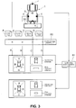
FIG. 3 is an explanatory diagram showing a flow of control to generate a peripheral overhead image, using a synthesizing pattern, based on captured images of a peripheral of a vehicle obtained by four cameras in which the controls are generated. -
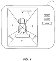
FIG. 4 is a schematic diagram showing modifications to a synthesizing pattern using a touch panel. - In the following text, a detailed description of examples will be given with reference to the drawings. It should be understood that various modifications to the examples may be made. In particular, elements of one example may be combined and used in other examples to form new examples.
- Next, a specific embodiment of a work vehicle of the present invention is described with reference to the drawings. In the present embodiment, the work vehicle may be a tractor which performs work using work equipment while traveling through a field (work site). As shown in
FIG. 1 , the exemplary tractor is provided with asteering unit 20 in the center of avehicle body 1 supported byfront wheels 11 andrear wheels 12.Work equipment 30, which in this example is rotary tilling equipment, is attached to the rear of thevehicle body 1 via ahydraulic lifting mechanism 31. Thefront wheels 11 function as the steering control wheels, and the traveling direction of the tractor is changed by changing the steering angle. The steering angle of thefront wheels 11 is changed by operating asteering mechanism 13. Asteering motor 14 is included in thesteering mechanism 13 for automatic steering. During manual operation, thefront wheels 11 can be steered by turning thesteering wheel 22 arranged inside thesteering unit 20. In thesteering unit 20, a touch panel 73 (one example of a display unit) is provided, thetouch panel 73 having a function of a notification device that provides information to the driver and a function of an input operation device that is operated by the driver. - A
satellite positioning module 70 in the form of a global navigation satellite system (GNSS) module is provided in a cabin 21 of the tractor. As a constituent element of thesatellite positioning module 70, a satellite antenna is mounted in a ceiling area of the cabin 21 to receive GNSS signals (including GPS signals). Thesatellite positioning module 70 can also include an inertial navigation module incorporating a gyro acceleration sensor and/or a magnetic direction sensor to complement satellite navigation. The inertial navigation module can of course be provided in a separate location from thesatellite positioning module 70. - In the example shown in
FIG. 1 , fourcameras 4 for imaging the periphery of the vehicle body are mounted on thevehicle body 1. In various embodiments and examples described herein, the "periphery" of the vehicle body may be understood as indicating an area proximate to the vehicle body and/or an area at least partially surrounding the vehicle body. In the example shown inFIG. 1 , thefirst camera 4 is arranged in the center of a front portion (hood) of the vehicle body, thesecond camera 4 and thethird camera 4 are arranged on left and right sides (rear wheel fenders) of the vehicle body, and thefourth camera 4 is arranged in the center of a rear portion (rear end of the cabin) of the vehicle body. Eachcamera 4 may capture, using an imaging element such as a charge-coupled device (CCD) and/or CMOS image sensor (CIS), two-dimensional images in chronological order at a speed of 15 to 30 frames per second, convert the images to digital images, and output the captured images in real time. The imaging optical axis of eachcamera 4 may face downward so that a part of thevehicle body 1 and/or thework equipment 30 as well as a field surface can be included in the field of view, and a wide-angle lens may be attached so that captured images of partial peripheral areas obtained by the fourcameras 4 can cover the entire periphery near the vehicle body. - Further, the tractor may be equipped with traveling
state detecting sensors 81 for detecting one or more states of the engine, transmission and/orsteering mechanism 13 etc., with workingstate detecting sensors 82 for detecting one or more states such as the orientation and/or position of thelifting mechanism 31 and/orwork equipment 30, and with arecognition unit 83 for recognizing a type of thework equipment 30 attached to thevehicle body 1. The workingstate detecting sensors 82 may include, but are not limited to, usage state detecting sensors for detecting one or more usage states such as orientation, ground clearance, and/or utilized width of thework equipment 30. Therecognition unit 83 may have a function to mechanically or electronically read an identification code of thework equipment 30 and derive, from the read identification code, one or more work equipment attribute values such as the type and/or size of the work equipment as recognition results. -
FIG. 2 shows an exemplary control system that may be built into the tractor. In the exemplary control system, technology is incorporated to display a peripheral overhead image created from captured images of a peripheral area of the work vehicle (e.g. thevehicle body 1 and the work equipment 30) captured by the plurality of cameras 4 (four cameras in the present embodiment), on atouch panel 73 serving as the display unit. In acontrol unit 5 which may be the main component of the exemplary control system, an input/outputsignal processing unit 7 is provided, which functions as an input/output interface. Output signal ports of the input/outputsignal processing unit 7 may be connected tovehicle travel devices 71,work equipment devices 72, thetouch panel 73, and one or more notification devices such as a lamp and/or speaker used to call attention of the driver and/or observer during operation. Thevehicle travel devices 71 may include, but are not limited to, thesteering motor 14 and one or more other devices such as a transmission mechanism and/or engine unit which are not shown in the drawing but are controlled for vehicle operation. Thework equipment devices 72 may include, but are not limited to, a drive mechanism for thework equipment 30 and/or alifting mechanism 31 used to raise and lower thework equipment 30, etc. - Input signal ports of the input/output
signal processing unit 7 may be connected to the above-statedcameras 4, thesatellite positioning module 70,work vehicle sensors 8, and an automatic/manualswitching operation tool 74. Thework vehicle sensors 8 may include, but are not limited to, the travelingstate detecting sensors 81 and/or the workingstate detecting sensors 82, and may further include therecognition unit 83 which has the function to read an identification code of the attachedwork equipment 30. The travelingstate detecting sensors 81 may include, but are not limited to, sensors for detecting the traveling state such as the steering angle, the engine speed, and/or the transmission state. The workingstate detecting sensors 82 may include, but are not limited to, sensors such as sensors for detecting the orientation and/or position of thework equipment 30. The automatic/manualswitching operation tool 74 may be a switch allowing the user to switch between an automatic traveling mode for traveling with automatic steering and a manual traveling mode for traveling with manual steering. For example, by operating the automatic/manualswitching operation tool 74 during the automatic steering mode, the traveling mode can be switched to the manual steering mode. Further, for example, by operating the automatic/manualswitching operation tool 74 during the manual steering mode, the traveling mode can be switched to the automatic steering mode. - While not shown in the drawings, a communication unit may also be connected to the input/output
signal processing unit 7. The communication unit may be configured to exchange data with one or more external computers via a wireless communication standard and/or a wired communication standard. The one or more external computers may include, but are not limited to, a management computer installed at a remote management center or the like as well as a tablet and/or smartphone (e.g. mobile phone) carried by the driver and/or observer. - In the exemplary configuration shown in
FIG. 2 , a travelingcontrol unit 50 that controls thevehicle travel devices 71 includes a manualtravel control unit 51 and an automatictravel control unit 52, since in this example the tractor is configured to be operable to travel either in the automatic travel (e.g. automatic steering) mode or the manual travel (e.g. manual steering) mode. The manualtravel control unit 51 may control thevehicle travel devices 71 based on operations performed by the driver. The automatictravel control unit 52 may generate one or more automatic steering commands based on deviations between vehicle positions and a travel course, and output these commands via the input/outputsignal processing unit 7 to thesteering motor 14. Awork control unit 53 may output one or more control signals to thework equipment devices 72 to control the operation of thework equipment 30. - The traveling
control unit 50 may perform different control procedures during automatic travel and manual travel. During automatic travel, the travelingcontrol unit 50 may achieve a function to compare and evaluate a vehicle position calculated by a vehicleposition calculating unit 54 and the travel course generated by acourse generating unit 58. When the vehicle position has deviated from the travel course, steering change data may be generated and outputted to the automatictravel control unit 52 so that thevehicle body 1 travels along the travel course. The vehicleposition calculating unit 54 may calculate the vehicle position on the basis of satellite positioning data sent from thesatellite positioning module 70. During manual travel, operation travel may be performed by operations of thesteering wheel 22 and/or the brakes etc. by the driver. At this time, the travel course and the vehicle position can be displayed on thetouch panel 73 and/or one or more external displays as travel guidance. - A work
site management unit 57 may manage field information (e.g. work site information) which is information related to the field in which the work is performed. The field information may include, but is not limited to, data such as a map location, shape, and/or size of the field, as well as a type of crop in the field. The field information can be provided to the worksite management unit 57, for example, by downloading from one or more computers installed at a remote management site and/or at a farmer's residence, by downloading from a portable device carried by the driver, and/or by reading from storage medium such as a USB memory. - The
course generating unit 58 may read outline data of the field from the field information and generates a travel course suitable for the field. The travel course can be generated automatically based on basic initial parameters inputted by the driver or can be generated by another computer and downloaded. In any case, the travel course obtained by thecourse generating unit 58 can be developed in the memory and used by the work vehicle, regardless of whether the travel is performed under automatic steering or manual steering, in order for the work vehicle to travel along the travel course. - The
control unit 5 may include a monitoringimage generating module 6 that generates a peripheral overhead image, as a control function particularly related to the present invention. The monitoringimage generating module 6 may include an overheadimage generating unit 60, a synthesizingpattern modifying unit 61, and animage synthesizing unit 62. In the example shown inFIG. 2 , the synthesizingpattern modifying unit 61 is incorporated into the monitoringimage generating module 6. The monitoringimage generating module 6 may have basic image processing functions, an overhead image generating function, and/or an overhead image synthesizing functions. The synthesizingpattern modifying unit 61 may be a functional unit that performs adjustments of the synthesizing process, and the synthesizingpattern modifying unit 61 may be configured separately from the monitoringimage generating module 6. The overheadimage generating unit 60 may change vantage points of the images captured by the fourcameras 4 to a vantage point above the center of the vehicle body, and generate a partial overhead image for eachcamera 4. These partial overhead images may have image regions which overlap with each other, and, by synthesizing these partial overhead images to join together, a peripheral overhead image which is an overhead image of the entire periphery of the tractor can be generated. These four partial overhead images can be joined together in different ways, and, depending on the manner in which these images are synthesized to join together, an area in the peripheral overhead image occupied by each of the partial overhead images can change. The way in which these images are synthesized to join together is referred to herein as a synthesizing pattern. The synthesizing pattern may determine the area of the peripheral overhead image occupied by each of the partial overhead images. The proportion of each partial overhead image in the peripheral overhead image can be changed by altering the synthesizing pattern. Theimage synthesizing unit 62 may synthesize the four partial overhead images based on the synthesizing pattern set by the synthesizingpattern modifying unit 61 and generate a peripheral overhead image. The synthesizingpattern modifying unit 61 may prepare a plurality of synthesizing patterns beforehand, select an appropriate synthesizing pattern from among the plurality of synthesizing patterns and input the selected synthesizing pattern to theimage synthesizing unit 62. Alternatively or additionally, the synthesizingpattern modifying unit 61 may adjust one or more existing basic synthesizing patterns to generate an appropriate synthesizing pattern and input the appropriate synthesizing pattern to theimage synthesizing unit 62. - The
control unit 5 may be implemented by a computer comprising a processor and a memory coupled to the processor. For example, the memory may store information and/or instructions to cause the processor to function as one or more functional units as stated above with reference toFIG. 2 . The processor may perform arithmetic, logic and/or control operations by accessing the memory. - Next, an example of a flow of control for generating a peripheral overhead image from the four partial overhead images using a synthesizing pattern is described with reference to
FIG. 3 . - Captured images obtained by the four
cameras 4 may be sent to the overheadimage generating unit 60. InFIG. 3 , the captured images from each of thecameras 4 are denoted by reference signs A to D in order to distinguish the captured images from each of thecameras 4. In the example shown inFIG. 3 , thecamera 4 for generating the captured image denoted by reference sign C has the peripheral area of thework equipment 30 as its field of view, and is configured to appropriately include the peripheral area of thework equipment 30 in its field of view, with regards to every size of thework equipment 30 that can be attached to thevehicle body 1. The four partial overhead images outputted from the overheadimage generating unit 60 may be synthesized to join together by theimage synthesizing unit 62 to form a peripheral overhead image. In the synthesis process, it may be important to use a synthesizing pattern with which a peripheral overhead image can be obtained such that the peripheral overhead image properly encompasses the peripheral area of thework equipment 30 attached to thevehicle body 1. - The
image synthesizing unit 62 may further apply, in a central portion of the generated peripheral overhead image, a work vehicle schematic including a vehicle body schematic prepared beforehand and a work equipment schematic corresponding to thework equipment 30 attached to the vehicle body. The peripheral overhead image with the work vehicle schematic outputted from theimage synthesizing unit 62 may be sent to a displayimage generating unit 56, converted to display image signals and sent to thetouch panel 73 and/or one or more external displays. - The following is a list of examples in which the synthesizing pattern is modified by the synthesizing
pattern modifying unit 61. - (1) The driver selects, using the
touch panel 73,work equipment 30 attached to the vehicle body, and the synthesizingpattern modifying unit 61 selects a synthesizing pattern most suitable for the selectedwork equipment 30 and sends the selected synthesizing pattern to theimage synthesizing unit 62. - (2) The driver selects an optimum peripheral overhead image from among peripheral overhead images displayed in order on the
touch panel 73, and the synthesizingpattern modifying unit 61 selects a synthesizing pattern that generates the selected peripheral overhead image and sends the selected synthesizing pattern to theimage synthesizing unit 62. - (3)
FIG. 4 shows modification of a synthesizing pattern in an exemplary case where, in a peripheral overhead image displayed on thetouch panel 73, both ends of thework equipment 30 are cut off in an area (denoted by the reference sign C) of the partial overhead image from thecamera 4 that has, as its field of view, a peripheral area of thework equipment 30 with a width. By pressing a modify button of thetouch panel 73, image boundary lines between the partial overhead images in the peripheral overhead image are displayed. When the driver moves the image boundary lines with a drag- and-drop operation, appropriate proportions of areas occupied by the partial overhead images are adjusted. When a complete button is pressed, the final positions of the image boundary lines are sent to the synthesizingpattern modifying unit 61 as modification commands. The synthesizingpattern modifying unit 61 then provides theimage synthesizing unit 62 with a synthesizing pattern based on the positions of the adjusted image boundary lines. - (4) The synthesizing
pattern modifying unit 61 selects an optimum synthesizing pattern based on the identification code of thework equipment 30 recognized by therecognition unit 83, and sends the pattern to theimage synthesizing unit 62. - (5) When
work equipment 30 in which the orientation and/or size thereof changes during the work operation is attached, for example, in case planting equipment of a foldable rice transplanter, tilling equipment and bucket equipment that is raised and lowered, and/or backhoe equipment that is raised, lowered, and rotated, is attached, the synthesizingpattern modifying unit 61 selects an optimum synthesizing pattern based on detection results of sensors (included in the working state detecting sensors 82) that detect changes in the orientation and/or size of thework equipment 30, and sends the selected synthesizing pattern to theimage synthesizing unit 62. - One or more of these examples can be used in combination.
- Use of a mapping table may be an effective way of performing image processing to generate a peripheral overhead image from captured images of a plurality of
cameras 4 as stated above. The mapping table may be a table that associates pixels in each captured image with pixels in a peripheral overhead image. Further, if a mapping table has been prepared beforehand for each of the synthesizing patterns that are used, a peripheral overhead image can be promptly obtained even when the synthesizing pattern is modified. -
- (1) In the embodiment described above, four
cameras 4 are used for imaging the periphery of the work vehicle. However, in some examples, more than fourcameras 4 may be used. Further, in some examples, a combination of one ormore cameras 4 capturing at least the periphery of thework equipment 30 and one ormore cameras 4 capturing something else may be used. - (2) In the embodiment described above, the peripheral overhead image generated by the monitoring
image generating module 6 is displayed on atouch panel 73 in the vehicle and/or one or more other displays. However, in case the vehicle is traveling unmanned, the generated peripheral overhead image can be sent using wireless communication to a communication terminal (e.g. tablet or smartphone) carried by an observer and/or another work vehicle monitoring the unmanned work vehicle and can be displayed on a display (an example of a display unit) provided thereof. In this case, not only the peripheral overhead image but also the captured images and the partial overhead images may be sent. Further, when a tablet computer and/or management computer that is (are) able to exchange data with the control system of the work vehicle via the input/outputsignal processing unit 7 is used, a configuration can be adopted where the tablet computer and/or management computer is used for modifying the synthesizing patterns in the manner described above, in addition to displaying a monitoring image such as the peripheral overhead image. In this way, the synthesizing pattern can be modified as necessary to display a desired monitoring image such as a desired peripheral overhead image at a place distant from the work vehicle and a remote management center and/or a farmer's residence. - (3) Each of the functional units in the functional block diagram shown in
FIG. 2 is differentiated for explanatory purposes. In reality, each of these functional units may be integrated with one or more other functional units or may be divided into a plurality of functional units. For example, the displayimage generating unit 56 may be integrated with the monitoringimage generating module 6, and/or the synthesizingpattern modifying unit 61 may be separated from the monitoringimage generating module 6. - (4) In the embodiment described above, the work vehicle is a tractor attached to work
equipment 30 in the form of rotary tilling equipment. However, various other work vehicles may be employed as embodiments, for example, an agricultural vehicle such as a rice transplanter, fertilizer, or combine, or a construction vehicle equipped with a dozer and/or roller etc. as thework equipment 30, or the like. - The present invention can be applied to a work vehicle displaying an overhead image on a monitor using a plurality of cameras.
-
- 1:
- Vehicle body
- 4:
- Camera
- 30:
- Work equipment
- 31:
- Lifting mechanism
- 5:
- Control unit
- 50:
- Traveling control unit
- 53:
- Work control unit
- 54:
- Vehicle position calculating unit
- 56:
- Display image generating unit
- 57:
- Work site management unit
- 58:
- Course generating unit
- 6:
- Monitoring image generating module
- 60:
- Overhead image generating unit
- 61:
- Synthesizing pattern modifying unit
- 62:
- Image synthesizing unit
- 70:
- Satellite positioning module
- 73:
- Touch panel (display unit, input operation device)
- 74:
- Manual switching operation tool
- 8:
- Work vehicle sensors
- 81:
- Traveling state detecting sensors
- 82:
- Working state detecting sensors (usage state detecting sensors)
- 83:
- Recognition unit
Claims (11)
- A work vehicle comprising a vehicle body (1) and work equipment (30) attached to the vehicle body (1), the work vehicle further comprising:a plurality of cameras (4) configured to image partial peripheral areas allocated from a peripheral area of the vehicle body (1) and the work equipment (30);a monitoring image generating module (6) configured to synthesize partial overhead images from each camera (4) on the basis of a modifiable synthesizing pattern, thereby generating a peripheral overhead image overlooking the peripheral area, the partial overhead images being generated by changing vantage points of captured images of the partial peripheral areas from each camera (4);a synthesizing pattern modifying unit (61) configured to modify the synthesizing pattern; anda display unit (73) configured to display the peripheral overhead image.
- A work vehicle according to claim 1, wherein the synthesizing pattern specifies occupied areas of the partial overhead images in the peripheral overhead image.
- A work vehicle according to claim 1 or 2, wherein the synthesizing pattern modifying unit (61) is configured to modify the synthesizing pattern on the basis of one or more modification commands received from an input operation device (73).
- A work vehicle according to claim 3, wherein the input operation device is a touch panel (73), and said one or more modification commands are generated by changing positions of image boundary lines between the partial overhead images in the peripheral overhead image displayed on the touch panel (73).
- A work vehicle according to any one of claims 1 to 4, further comprising a recognition unit (83) configured to recognize a type of the work equipment (30),
wherein the synthesizing pattern modifying unit (61) is configured to modify the synthesizing pattern on the basis of one or more recognition results from the recognition unit (83). - A work vehicle according to any one of claims 1 to 5, further comprising a usage state detecting sensor (81) configured to detect a usage state of the work equipment (30),
wherein the synthesizing pattern modifying unit (61) is configured to modify the synthesizing pattern on the basis of one or more detection results from the usage state detecting sensor (81). - A work vehicle according to any one of claims 1 to 6, wherein a work vehicle schematic is provided in a center of the peripheral overhead image, the work vehicle schematic including a vehicle body schematic showing the vehicle body (1) and a work equipment schematic showing the work equipment (30), and wherein a size of the work equipment schematic is modified as the synthesizing pattern is modified.
- A method for generating a peripheral overhead image overlooking a peripheral area of a vehicle body (1) and work equipment (30) attached to the vehicle body, the method comprising:receiving, by a control unit (5) from a plurality of cameras (4) attached to the vehicle body (1), captured images of partial peripheral areas allocated from the peripheral area of the vehicle body (1) and the work equipment (30);generating, by the control unit (5), partial overhead images from each camera (4) by changing vantage points of the captured images of the partial peripheral areas from each camera (4);synthesizing, by the control unit (5), the partial overhead images from each camera (4) on the basis of a modifiable synthesizing pattern, thereby generating a peripheral overhead image overlooking the peripheral area; andproviding the peripheral overhead image from the control unit (5) to a display unit (73) for displaying the peripheral overhead image on the display unit (73).
- The method according to claim 8, the method further comprising:modifying the synthesizing pattern by the control unit (5); andgenerating, by the control unit (5), a modified peripheral overhead image overlooking the peripheral area by synthesizing the partial overhead images from each camera on the basis of the modified synthesizing pattern.
- A system for generating a peripheral overhead image overlooking a peripheral area of a vehicle body (1) and work equipment (30) attached to the vehicle body, the system comprising:a control unit (5) configured to perform the method according to any one of claim 8 or 9; anda display unit (73) configured to display the peripheral overhead image.
- A computer program product comprising computer-readable instructions that, when loaded and run on a computer, cause the computer to perform the method according to claim 8 or 9.
Applications Claiming Priority (1)
| Application Number | Priority Date | Filing Date | Title |
|---|---|---|---|
| JP2016245943A JP6662762B2 (en) | 2016-12-19 | 2016-12-19 | Work vehicle |
Publications (2)
| Publication Number | Publication Date |
|---|---|
| EP3335944A1 true EP3335944A1 (en) | 2018-06-20 |
| EP3335944B1 EP3335944B1 (en) | 2021-08-11 |
Family
ID=58992594
Family Applications (1)
| Application Number | Title | Priority Date | Filing Date |
|---|---|---|---|
| EP17000886.6A Active EP3335944B1 (en) | 2016-12-19 | 2017-05-23 | Work vehicle |
Country Status (5)
| Country | Link |
|---|---|
| US (1) | US10538200B2 (en) |
| EP (1) | EP3335944B1 (en) |
| JP (1) | JP6662762B2 (en) |
| KR (1) | KR102262871B1 (en) |
| CN (1) | CN108202667B (en) |
Cited By (3)
| Publication number | Priority date | Publication date | Assignee | Title |
|---|---|---|---|---|
| WO2019091725A1 (en) * | 2017-11-10 | 2019-05-16 | Zf Friedrichshafen Ag | Method and display device for guiding a working machine |
| CN109982039A (en) * | 2019-03-20 | 2019-07-05 | 西安鸣士机电开发有限公司 | A kind of remote visualization remote control device for rice transplanter |
| WO2025024091A1 (en) * | 2023-07-24 | 2025-01-30 | Caterpillar Inc. | Surround view monitoring method for a work machine and the work machine |
Families Citing this family (15)
| Publication number | Priority date | Publication date | Assignee | Title |
|---|---|---|---|---|
| JP2019032682A (en) * | 2017-08-08 | 2019-02-28 | ヤンマー株式会社 | Automated driving system |
| US10820508B2 (en) * | 2018-08-20 | 2020-11-03 | Cnh Industrial America Llc | System and method for operating an agricultural harvester |
| US11772556B2 (en) * | 2018-10-31 | 2023-10-03 | Komatsu Ltd. | Display control system and display control method |
| JP7038643B2 (en) * | 2018-11-26 | 2022-03-18 | 本田技研工業株式会社 | Video display device |
| JP7283059B2 (en) * | 2018-11-28 | 2023-05-30 | 株式会社アイシン | Perimeter monitoring device |
| WO2020134236A1 (en) * | 2018-12-29 | 2020-07-02 | 丰疆智能科技股份有限公司 | Harvester and automatic driving method thereof |
| US12513263B2 (en) | 2019-01-30 | 2025-12-30 | Roosevelt Roberson | Vehicle camera and record system |
| JP7271218B2 (en) * | 2019-02-22 | 2023-05-11 | 株式会社加藤製作所 | construction machinery |
| JP7174485B2 (en) * | 2019-03-20 | 2022-11-17 | 株式会社クボタ | harvester |
| CN113795140A (en) * | 2019-03-20 | 2021-12-14 | 株式会社久保田 | Harvesting machine |
| JP7317533B2 (en) * | 2019-03-20 | 2023-07-31 | 株式会社クボタ | harvester |
| JP7391604B2 (en) * | 2019-10-23 | 2023-12-05 | 株式会社加藤製作所 | construction machinery |
| US11653587B2 (en) * | 2020-09-17 | 2023-05-23 | Deere & Company | System and method for presenting the surroundings of an agricultural implement |
| US20260051180A1 (en) | 2022-09-22 | 2026-02-19 | Sony Semiconductor Solutions Corporation | Information processing device and information processing method |
| KR102759186B1 (en) | 2024-05-22 | 2025-01-22 | 남영우 | Work Area Guidance Device for Work Vehicle Installation |
Citations (5)
| Publication number | Priority date | Publication date | Assignee | Title |
|---|---|---|---|---|
| US20110074916A1 (en) * | 2009-09-29 | 2011-03-31 | Toyota Motor Engin. & Manufact. N.A. (TEMA) | Electronic control system, electronic control unit and associated methodology of adapting 3d panoramic views of vehicle surroundings by predicting driver intent |
| US20130147958A1 (en) * | 2011-06-07 | 2013-06-13 | Komatsu Ltd. | Perimeter monitoring device for work vehicle |
| JP2015104375A (en) | 2013-12-02 | 2015-06-08 | ヤンマー株式会社 | Combine |
| US20160200252A1 (en) * | 2014-01-23 | 2016-07-14 | Hitachi Construction Machinery Co., Ltd. | Surroundings monitoring device for work machine |
| US20160301864A1 (en) * | 2015-04-10 | 2016-10-13 | Caterpillar Inc. | Imaging processing system for generating a surround-view image |
Family Cites Families (20)
| Publication number | Priority date | Publication date | Assignee | Title |
|---|---|---|---|---|
| JP4179262B2 (en) * | 2004-10-06 | 2008-11-12 | ソニー株式会社 | Information processing apparatus and method, and program |
| JP4639753B2 (en) * | 2004-10-25 | 2011-02-23 | 日産自動車株式会社 | Driving assistance device |
| JP4863347B2 (en) * | 2005-11-02 | 2012-01-25 | ヤンマー株式会社 | Attitude control device |
| JP4606322B2 (en) * | 2005-12-27 | 2011-01-05 | アルパイン株式会社 | Vehicle driving support device |
| JP2009100342A (en) * | 2007-10-18 | 2009-05-07 | Sanyo Electric Co Ltd | Camera calibration device, method and vehicle |
| JP5112998B2 (en) * | 2008-09-16 | 2013-01-09 | 本田技研工業株式会社 | Vehicle perimeter monitoring device |
| JP5066198B2 (en) * | 2010-02-09 | 2012-11-07 | 住友建機株式会社 | Work machine monitoring device |
| JP5269026B2 (en) * | 2010-09-29 | 2013-08-21 | 日立建機株式会社 | Work machine ambient monitoring device |
| JP2012105158A (en) * | 2010-11-11 | 2012-05-31 | Mitsubishi Fuso Truck & Bus Corp | Combination vehicle birds-eye-view display system |
| WO2012157379A1 (en) * | 2011-05-13 | 2012-11-22 | 日立建機株式会社 | Device for monitoring area around working machine |
| US20140111648A1 (en) * | 2011-06-02 | 2014-04-24 | Hitachi Contruction Machinery Co., Ltd. | Device For Monitoring Area Around Working Machine |
| JP5506864B2 (en) * | 2011-06-20 | 2014-05-28 | 富士フイルム株式会社 | Image processing apparatus, image processing method, and image processing program |
| AU2013208525A1 (en) * | 2012-01-12 | 2014-08-14 | Hitachi Construction Machinery Co., Ltd. | Periphery monitoring device for self-propelled industrial machine |
| JP5529943B2 (en) * | 2012-09-21 | 2014-06-25 | 株式会社小松製作所 | Work vehicle periphery monitoring system and work vehicle |
| CN105682446B (en) * | 2013-10-01 | 2018-06-08 | 洋马株式会社 | Combine harvester |
| KR102123127B1 (en) * | 2013-12-06 | 2020-06-15 | 두산인프라코어 주식회사 | Apparatus for selecting screen mode and method |
| US9530086B1 (en) * | 2015-10-27 | 2016-12-27 | Cnh Industrial America Llc | Scanned software activation codes in agricultural and contruction work equipment systems |
| DE112016000037B4 (en) * | 2016-03-28 | 2020-04-02 | Komatsu Ltd. | Evaluation device and evaluation method |
| JP6802008B2 (en) * | 2016-08-25 | 2020-12-16 | キャタピラー エス エー アール エル | Construction machinery |
| AU2017331287A1 (en) * | 2016-09-23 | 2019-05-02 | Esco Group Llc | Asset management system |
-
2016
- 2016-12-19 JP JP2016245943A patent/JP6662762B2/en active Active
-
2017
- 2017-05-23 EP EP17000886.6A patent/EP3335944B1/en active Active
- 2017-05-31 CN CN201710398227.XA patent/CN108202667B/en active Active
- 2017-05-31 KR KR1020170067882A patent/KR102262871B1/en active Active
- 2017-06-19 US US15/626,185 patent/US10538200B2/en active Active
Patent Citations (5)
| Publication number | Priority date | Publication date | Assignee | Title |
|---|---|---|---|---|
| US20110074916A1 (en) * | 2009-09-29 | 2011-03-31 | Toyota Motor Engin. & Manufact. N.A. (TEMA) | Electronic control system, electronic control unit and associated methodology of adapting 3d panoramic views of vehicle surroundings by predicting driver intent |
| US20130147958A1 (en) * | 2011-06-07 | 2013-06-13 | Komatsu Ltd. | Perimeter monitoring device for work vehicle |
| JP2015104375A (en) | 2013-12-02 | 2015-06-08 | ヤンマー株式会社 | Combine |
| US20160200252A1 (en) * | 2014-01-23 | 2016-07-14 | Hitachi Construction Machinery Co., Ltd. | Surroundings monitoring device for work machine |
| US20160301864A1 (en) * | 2015-04-10 | 2016-10-13 | Caterpillar Inc. | Imaging processing system for generating a surround-view image |
Cited By (3)
| Publication number | Priority date | Publication date | Assignee | Title |
|---|---|---|---|---|
| WO2019091725A1 (en) * | 2017-11-10 | 2019-05-16 | Zf Friedrichshafen Ag | Method and display device for guiding a working machine |
| CN109982039A (en) * | 2019-03-20 | 2019-07-05 | 西安鸣士机电开发有限公司 | A kind of remote visualization remote control device for rice transplanter |
| WO2025024091A1 (en) * | 2023-07-24 | 2025-01-30 | Caterpillar Inc. | Surround view monitoring method for a work machine and the work machine |
Also Published As
| Publication number | Publication date |
|---|---|
| KR20180071152A (en) | 2018-06-27 |
| US10538200B2 (en) | 2020-01-21 |
| US20180170258A1 (en) | 2018-06-21 |
| JP6662762B2 (en) | 2020-03-11 |
| CN108202667A (en) | 2018-06-26 |
| EP3335944B1 (en) | 2021-08-11 |
| CN108202667B (en) | 2022-05-03 |
| JP2018101860A (en) | 2018-06-28 |
| KR102262871B1 (en) | 2021-06-09 |
Similar Documents
| Publication | Publication Date | Title |
|---|---|---|
| EP3335944B1 (en) | Work vehicle | |
| US10491818B2 (en) | Work vehicle with monitor to display overhead image of work vehicle, and image displaying method for displaying overhead image of work vehicle | |
| US9990543B2 (en) | Vehicle exterior moving object detection system | |
| US10324461B2 (en) | Remote control apparatus | |
| JP7283059B2 (en) | Perimeter monitoring device | |
| US10598505B2 (en) | Travel route generation apparatus and method for generating travel route | |
| US9335545B2 (en) | Head mountable display system | |
| JP7287262B2 (en) | Remote control system and remote control server | |
| JP6253565B2 (en) | Operation terminal | |
| JP7797546B2 (en) | Display control system and display control method | |
| JP2018116608A (en) | Travel route generation device and travel route generation program | |
| JP7076501B2 (en) | Work vehicle | |
| CN108432234B (en) | Terminal device, control device, data integration device, work vehicle, imaging system, and imaging method | |
| JP2021119649A (en) | Server and system for work support | |
| WO2024143437A1 (en) | Remote control apparatus and remote manipulation system | |
| JP2019024383A (en) | Field management system | |
| EP4455821B1 (en) | Working robot system | |
| JP7055158B2 (en) | Work vehicle | |
| CN118614057A (en) | Remote operation support system and remote operation support method | |
| KR20230156220A (en) | Around view monitoring system for construction machinary and around view image generating method using the same | |
| JP2018203090A (en) | Parking support device, parking support system, parking support method and program | |
| JP2007088577A (en) | Vehicle periphery image processing system | |
| JP7720727B2 (en) | Information processing device and control program for information processing device | |
| JP2025174357A (en) | Display control method and display control system | |
| JP2020095420A (en) | Vehicle accompanying system and vehicle accompanying method |
Legal Events
| Date | Code | Title | Description |
|---|---|---|---|
| PUAI | Public reference made under article 153(3) epc to a published international application that has entered the european phase |
Free format text: ORIGINAL CODE: 0009012 |
|
| STAA | Information on the status of an ep patent application or granted ep patent |
Free format text: STATUS: THE APPLICATION HAS BEEN PUBLISHED |
|
| AK | Designated contracting states |
Kind code of ref document: A1 Designated state(s): AL AT BE BG CH CY CZ DE DK EE ES FI FR GB GR HR HU IE IS IT LI LT LU LV MC MK MT NL NO PL PT RO RS SE SI SK SM TR |
|
| AX | Request for extension of the european patent |
Extension state: BA ME |
|
| STAA | Information on the status of an ep patent application or granted ep patent |
Free format text: STATUS: REQUEST FOR EXAMINATION WAS MADE |
|
| 17P | Request for examination filed |
Effective date: 20181220 |
|
| RBV | Designated contracting states (corrected) |
Designated state(s): AL AT BE BG CH CY CZ DE DK EE ES FI FR GB GR HR HU IE IS IT LI LT LU LV MC MK MT NL NO PL PT RO RS SE SI SK SM TR |
|
| STAA | Information on the status of an ep patent application or granted ep patent |
Free format text: STATUS: EXAMINATION IS IN PROGRESS |
|
| 17Q | First examination report despatched |
Effective date: 20200903 |
|
| GRAP | Despatch of communication of intention to grant a patent |
Free format text: ORIGINAL CODE: EPIDOSNIGR1 |
|
| STAA | Information on the status of an ep patent application or granted ep patent |
Free format text: STATUS: GRANT OF PATENT IS INTENDED |
|
| INTG | Intention to grant announced |
Effective date: 20210514 |
|
| GRAS | Grant fee paid |
Free format text: ORIGINAL CODE: EPIDOSNIGR3 |
|
| GRAA | (expected) grant |
Free format text: ORIGINAL CODE: 0009210 |
|
| STAA | Information on the status of an ep patent application or granted ep patent |
Free format text: STATUS: THE PATENT HAS BEEN GRANTED |
|
| AK | Designated contracting states |
Kind code of ref document: B1 Designated state(s): AL AT BE BG CH CY CZ DE DK EE ES FI FR GB GR HR HU IE IS IT LI LT LU LV MC MK MT NL NO PL PT RO RS SE SI SK SM TR |
|
| REG | Reference to a national code |
Ref country code: CH Ref legal event code: EP |
|
| REG | Reference to a national code |
Ref country code: DE Ref legal event code: R096 Ref document number: 602017043677 Country of ref document: DE |
|
| REG | Reference to a national code |
Ref country code: IE Ref legal event code: FG4D Ref country code: AT Ref legal event code: REF Ref document number: 1419081 Country of ref document: AT Kind code of ref document: T Effective date: 20210915 |
|
| REG | Reference to a national code |
Ref country code: LT Ref legal event code: MG9D |
|
| REG | Reference to a national code |
Ref country code: NL Ref legal event code: MP Effective date: 20210811 |
|
| REG | Reference to a national code |
Ref country code: AT Ref legal event code: MK05 Ref document number: 1419081 Country of ref document: AT Kind code of ref document: T Effective date: 20210811 |
|
| PG25 | Lapsed in a contracting state [announced via postgrant information from national office to epo] |
Ref country code: RS Free format text: LAPSE BECAUSE OF FAILURE TO SUBMIT A TRANSLATION OF THE DESCRIPTION OR TO PAY THE FEE WITHIN THE PRESCRIBED TIME-LIMIT Effective date: 20210811 Ref country code: SE Free format text: LAPSE BECAUSE OF FAILURE TO SUBMIT A TRANSLATION OF THE DESCRIPTION OR TO PAY THE FEE WITHIN THE PRESCRIBED TIME-LIMIT Effective date: 20210811 Ref country code: PT Free format text: LAPSE BECAUSE OF FAILURE TO SUBMIT A TRANSLATION OF THE DESCRIPTION OR TO PAY THE FEE WITHIN THE PRESCRIBED TIME-LIMIT Effective date: 20211213 Ref country code: NO Free format text: LAPSE BECAUSE OF FAILURE TO SUBMIT A TRANSLATION OF THE DESCRIPTION OR TO PAY THE FEE WITHIN THE PRESCRIBED TIME-LIMIT Effective date: 20211111 Ref country code: FI Free format text: LAPSE BECAUSE OF FAILURE TO SUBMIT A TRANSLATION OF THE DESCRIPTION OR TO PAY THE FEE WITHIN THE PRESCRIBED TIME-LIMIT Effective date: 20210811 Ref country code: ES Free format text: LAPSE BECAUSE OF FAILURE TO SUBMIT A TRANSLATION OF THE DESCRIPTION OR TO PAY THE FEE WITHIN THE PRESCRIBED TIME-LIMIT Effective date: 20210811 Ref country code: HR Free format text: LAPSE BECAUSE OF FAILURE TO SUBMIT A TRANSLATION OF THE DESCRIPTION OR TO PAY THE FEE WITHIN THE PRESCRIBED TIME-LIMIT Effective date: 20210811 Ref country code: AT Free format text: LAPSE BECAUSE OF FAILURE TO SUBMIT A TRANSLATION OF THE DESCRIPTION OR TO PAY THE FEE WITHIN THE PRESCRIBED TIME-LIMIT Effective date: 20210811 Ref country code: BG Free format text: LAPSE BECAUSE OF FAILURE TO SUBMIT A TRANSLATION OF THE DESCRIPTION OR TO PAY THE FEE WITHIN THE PRESCRIBED TIME-LIMIT Effective date: 20211111 Ref country code: LT Free format text: LAPSE BECAUSE OF FAILURE TO SUBMIT A TRANSLATION OF THE DESCRIPTION OR TO PAY THE FEE WITHIN THE PRESCRIBED TIME-LIMIT Effective date: 20210811 |
|
| PG25 | Lapsed in a contracting state [announced via postgrant information from national office to epo] |
Ref country code: PL Free format text: LAPSE BECAUSE OF FAILURE TO SUBMIT A TRANSLATION OF THE DESCRIPTION OR TO PAY THE FEE WITHIN THE PRESCRIBED TIME-LIMIT Effective date: 20210811 Ref country code: LV Free format text: LAPSE BECAUSE OF FAILURE TO SUBMIT A TRANSLATION OF THE DESCRIPTION OR TO PAY THE FEE WITHIN THE PRESCRIBED TIME-LIMIT Effective date: 20210811 Ref country code: GR Free format text: LAPSE BECAUSE OF FAILURE TO SUBMIT A TRANSLATION OF THE DESCRIPTION OR TO PAY THE FEE WITHIN THE PRESCRIBED TIME-LIMIT Effective date: 20211112 |
|
| PG25 | Lapsed in a contracting state [announced via postgrant information from national office to epo] |
Ref country code: NL Free format text: LAPSE BECAUSE OF FAILURE TO SUBMIT A TRANSLATION OF THE DESCRIPTION OR TO PAY THE FEE WITHIN THE PRESCRIBED TIME-LIMIT Effective date: 20210811 |
|
| PG25 | Lapsed in a contracting state [announced via postgrant information from national office to epo] |
Ref country code: DK Free format text: LAPSE BECAUSE OF FAILURE TO SUBMIT A TRANSLATION OF THE DESCRIPTION OR TO PAY THE FEE WITHIN THE PRESCRIBED TIME-LIMIT Effective date: 20210811 |
|
| REG | Reference to a national code |
Ref country code: DE Ref legal event code: R097 Ref document number: 602017043677 Country of ref document: DE |
|
| PG25 | Lapsed in a contracting state [announced via postgrant information from national office to epo] |
Ref country code: SM Free format text: LAPSE BECAUSE OF FAILURE TO SUBMIT A TRANSLATION OF THE DESCRIPTION OR TO PAY THE FEE WITHIN THE PRESCRIBED TIME-LIMIT Effective date: 20210811 Ref country code: SK Free format text: LAPSE BECAUSE OF FAILURE TO SUBMIT A TRANSLATION OF THE DESCRIPTION OR TO PAY THE FEE WITHIN THE PRESCRIBED TIME-LIMIT Effective date: 20210811 Ref country code: RO Free format text: LAPSE BECAUSE OF FAILURE TO SUBMIT A TRANSLATION OF THE DESCRIPTION OR TO PAY THE FEE WITHIN THE PRESCRIBED TIME-LIMIT Effective date: 20210811 Ref country code: EE Free format text: LAPSE BECAUSE OF FAILURE TO SUBMIT A TRANSLATION OF THE DESCRIPTION OR TO PAY THE FEE WITHIN THE PRESCRIBED TIME-LIMIT Effective date: 20210811 Ref country code: CZ Free format text: LAPSE BECAUSE OF FAILURE TO SUBMIT A TRANSLATION OF THE DESCRIPTION OR TO PAY THE FEE WITHIN THE PRESCRIBED TIME-LIMIT Effective date: 20210811 Ref country code: AL Free format text: LAPSE BECAUSE OF FAILURE TO SUBMIT A TRANSLATION OF THE DESCRIPTION OR TO PAY THE FEE WITHIN THE PRESCRIBED TIME-LIMIT Effective date: 20210811 |
|
| PLBE | No opposition filed within time limit |
Free format text: ORIGINAL CODE: 0009261 |
|
| STAA | Information on the status of an ep patent application or granted ep patent |
Free format text: STATUS: NO OPPOSITION FILED WITHIN TIME LIMIT |
|
| 26N | No opposition filed |
Effective date: 20220512 |
|
| PG25 | Lapsed in a contracting state [announced via postgrant information from national office to epo] |
Ref country code: IT Free format text: LAPSE BECAUSE OF FAILURE TO SUBMIT A TRANSLATION OF THE DESCRIPTION OR TO PAY THE FEE WITHIN THE PRESCRIBED TIME-LIMIT Effective date: 20210811 |
|
| PG25 | Lapsed in a contracting state [announced via postgrant information from national office to epo] |
Ref country code: SI Free format text: LAPSE BECAUSE OF FAILURE TO SUBMIT A TRANSLATION OF THE DESCRIPTION OR TO PAY THE FEE WITHIN THE PRESCRIBED TIME-LIMIT Effective date: 20210811 |
|
| REG | Reference to a national code |
Ref country code: CH Ref legal event code: PL |
|
| REG | Reference to a national code |
Ref country code: BE Ref legal event code: MM Effective date: 20220531 |
|
| GBPC | Gb: european patent ceased through non-payment of renewal fee |
Effective date: 20220523 |
|
| PG25 | Lapsed in a contracting state [announced via postgrant information from national office to epo] |
Ref country code: MC Free format text: LAPSE BECAUSE OF FAILURE TO SUBMIT A TRANSLATION OF THE DESCRIPTION OR TO PAY THE FEE WITHIN THE PRESCRIBED TIME-LIMIT Effective date: 20210811 Ref country code: LU Free format text: LAPSE BECAUSE OF NON-PAYMENT OF DUE FEES Effective date: 20220523 Ref country code: LI Free format text: LAPSE BECAUSE OF NON-PAYMENT OF DUE FEES Effective date: 20220531 Ref country code: CH Free format text: LAPSE BECAUSE OF NON-PAYMENT OF DUE FEES Effective date: 20220531 |
|
| PG25 | Lapsed in a contracting state [announced via postgrant information from national office to epo] |
Ref country code: IE Free format text: LAPSE BECAUSE OF NON-PAYMENT OF DUE FEES Effective date: 20220523 |
|
| PG25 | Lapsed in a contracting state [announced via postgrant information from national office to epo] |
Ref country code: GB Free format text: LAPSE BECAUSE OF NON-PAYMENT OF DUE FEES Effective date: 20220523 Ref country code: BE Free format text: LAPSE BECAUSE OF NON-PAYMENT OF DUE FEES Effective date: 20220531 |
|
| PG25 | Lapsed in a contracting state [announced via postgrant information from national office to epo] |
Ref country code: HU Free format text: LAPSE BECAUSE OF FAILURE TO SUBMIT A TRANSLATION OF THE DESCRIPTION OR TO PAY THE FEE WITHIN THE PRESCRIBED TIME-LIMIT; INVALID AB INITIO Effective date: 20170523 |
|
| PG25 | Lapsed in a contracting state [announced via postgrant information from national office to epo] |
Ref country code: MK Free format text: LAPSE BECAUSE OF FAILURE TO SUBMIT A TRANSLATION OF THE DESCRIPTION OR TO PAY THE FEE WITHIN THE PRESCRIBED TIME-LIMIT Effective date: 20210811 Ref country code: CY Free format text: LAPSE BECAUSE OF FAILURE TO SUBMIT A TRANSLATION OF THE DESCRIPTION OR TO PAY THE FEE WITHIN THE PRESCRIBED TIME-LIMIT Effective date: 20210811 |
|
| PG25 | Lapsed in a contracting state [announced via postgrant information from national office to epo] |
Ref country code: TR Free format text: LAPSE BECAUSE OF FAILURE TO SUBMIT A TRANSLATION OF THE DESCRIPTION OR TO PAY THE FEE WITHIN THE PRESCRIBED TIME-LIMIT Effective date: 20210811 |
|
| PG25 | Lapsed in a contracting state [announced via postgrant information from national office to epo] |
Ref country code: MT Free format text: LAPSE BECAUSE OF FAILURE TO SUBMIT A TRANSLATION OF THE DESCRIPTION OR TO PAY THE FEE WITHIN THE PRESCRIBED TIME-LIMIT Effective date: 20210811 |
|
| PGFP | Annual fee paid to national office [announced via postgrant information from national office to epo] |
Ref country code: DE Payment date: 20250402 Year of fee payment: 9 |
|
| PGFP | Annual fee paid to national office [announced via postgrant information from national office to epo] |
Ref country code: FR Payment date: 20250401 Year of fee payment: 9 |