EP3335894B1 - Printer with image inspection device - Google Patents
Printer with image inspection device Download PDFInfo
- Publication number
- EP3335894B1 EP3335894B1 EP17206380.2A EP17206380A EP3335894B1 EP 3335894 B1 EP3335894 B1 EP 3335894B1 EP 17206380 A EP17206380 A EP 17206380A EP 3335894 B1 EP3335894 B1 EP 3335894B1
- Authority
- EP
- European Patent Office
- Prior art keywords
- media
- transport path
- switch
- image
- printed
- Prior art date
- Legal status (The legal status is an assumption and is not a legal conclusion. Google has not performed a legal analysis and makes no representation as to the accuracy of the status listed.)
- Not-in-force
Links
Images

Classifications
-
- B—PERFORMING OPERATIONS; TRANSPORTING
- B41—PRINTING; LINING MACHINES; TYPEWRITERS; STAMPS
- B41J—TYPEWRITERS; SELECTIVE PRINTING MECHANISMS, i.e. MECHANISMS PRINTING OTHERWISE THAN FROM A FORME; CORRECTION OF TYPOGRAPHICAL ERRORS
- B41J13/00—Devices or arrangements of selective printing mechanisms, e.g. ink-jet printers or thermal printers, specially adapted for supporting or handling copy material in short lengths, e.g. sheets
- B41J13/0009—Devices or arrangements of selective printing mechanisms, e.g. ink-jet printers or thermal printers, specially adapted for supporting or handling copy material in short lengths, e.g. sheets control of the transport of the copy material
-
- B—PERFORMING OPERATIONS; TRANSPORTING
- B41—PRINTING; LINING MACHINES; TYPEWRITERS; STAMPS
- B41J—TYPEWRITERS; SELECTIVE PRINTING MECHANISMS, i.e. MECHANISMS PRINTING OTHERWISE THAN FROM A FORME; CORRECTION OF TYPOGRAPHICAL ERRORS
- B41J2/00—Typewriters or selective printing mechanisms characterised by the printing or marking process for which they are designed
- B41J2/005—Typewriters or selective printing mechanisms characterised by the printing or marking process for which they are designed characterised by bringing liquid or particles selectively into contact with a printing material
- B41J2/01—Ink jet
- B41J2/21—Ink jet for multi-colour printing
- B41J2/2132—Print quality control characterised by dot disposition, e.g. for reducing white stripes or banding
- B41J2/2142—Detection of malfunctioning nozzles
-
- B—PERFORMING OPERATIONS; TRANSPORTING
- B02—CRUSHING, PULVERISING, OR DISINTEGRATING; PREPARATORY TREATMENT OF GRAIN FOR MILLING
- B02C—CRUSHING, PULVERISING, OR DISINTEGRATING IN GENERAL; MILLING GRAIN
- B02C18/00—Disintegrating by knives or other cutting or tearing members which chop material into fragments
-
- B—PERFORMING OPERATIONS; TRANSPORTING
- B41—PRINTING; LINING MACHINES; TYPEWRITERS; STAMPS
- B41J—TYPEWRITERS; SELECTIVE PRINTING MECHANISMS, i.e. MECHANISMS PRINTING OTHERWISE THAN FROM A FORME; CORRECTION OF TYPOGRAPHICAL ERRORS
- B41J11/00—Devices or arrangements of selective printing mechanisms, e.g. ink-jet printers or thermal printers, for supporting or handling copy material in sheet or web form
- B41J11/66—Applications of cutting devices
- B41J11/663—Controlling cutting, cutting resulting in special shapes of the cutting line, e.g. controlling cutting positions, e.g. for cutting in the immediate vicinity of a printed image
-
- B—PERFORMING OPERATIONS; TRANSPORTING
- B41—PRINTING; LINING MACHINES; TYPEWRITERS; STAMPS
- B41J—TYPEWRITERS; SELECTIVE PRINTING MECHANISMS, i.e. MECHANISMS PRINTING OTHERWISE THAN FROM A FORME; CORRECTION OF TYPOGRAPHICAL ERRORS
- B41J11/00—Devices or arrangements of selective printing mechanisms, e.g. ink-jet printers or thermal printers, for supporting or handling copy material in sheet or web form
- B41J11/66—Applications of cutting devices
- B41J11/70—Applications of cutting devices cutting perpendicular to the direction of paper feed
-
- B—PERFORMING OPERATIONS; TRANSPORTING
- B41—PRINTING; LINING MACHINES; TYPEWRITERS; STAMPS
- B41J—TYPEWRITERS; SELECTIVE PRINTING MECHANISMS, i.e. MECHANISMS PRINTING OTHERWISE THAN FROM A FORME; CORRECTION OF TYPOGRAPHICAL ERRORS
- B41J13/00—Devices or arrangements of selective printing mechanisms, e.g. ink-jet printers or thermal printers, specially adapted for supporting or handling copy material in short lengths, e.g. sheets
- B41J13/009—Diverting sheets at a section where at least two sheet conveying paths converge, e.g. by a movable switching guide that blocks access to one conveying path and guides the sheet to another path, e.g. when a sheet conveying direction is reversed after printing on the front of the sheet has been finished and the sheet is guided to a sheet turning path for printing on the back
-
- B—PERFORMING OPERATIONS; TRANSPORTING
- B41—PRINTING; LINING MACHINES; TYPEWRITERS; STAMPS
- B41J—TYPEWRITERS; SELECTIVE PRINTING MECHANISMS, i.e. MECHANISMS PRINTING OTHERWISE THAN FROM A FORME; CORRECTION OF TYPOGRAPHICAL ERRORS
- B41J15/00—Devices or arrangements of selective printing mechanisms, e.g. ink-jet printers or thermal printers, specially adapted for supporting or handling copy material in continuous form, e.g. webs
- B41J15/04—Supporting, feeding, or guiding devices; Mountings for web rolls or spindles
-
- B—PERFORMING OPERATIONS; TRANSPORTING
- B41—PRINTING; LINING MACHINES; TYPEWRITERS; STAMPS
- B41J—TYPEWRITERS; SELECTIVE PRINTING MECHANISMS, i.e. MECHANISMS PRINTING OTHERWISE THAN FROM A FORME; CORRECTION OF TYPOGRAPHICAL ERRORS
- B41J29/00—Details of, or accessories for, typewriters or selective printing mechanisms not otherwise provided for
- B41J29/38—Drives, motors, controls or automatic cut-off devices for the entire printing mechanism
- B41J29/393—Devices for controlling or analysing the entire machine ; Controlling or analysing mechanical parameters involving printing of test patterns
-
- B—PERFORMING OPERATIONS; TRANSPORTING
- B65—CONVEYING; PACKING; STORING; HANDLING THIN OR FILAMENTARY MATERIAL
- B65H—HANDLING THIN OR FILAMENTARY MATERIAL, e.g. SHEETS, WEBS, CABLES
- B65H29/00—Delivering or advancing articles from machines; Advancing articles to or into piles
- B65H29/12—Delivering or advancing articles from machines; Advancing articles to or into piles by means of the nip between two, or between two sets of, moving tapes or bands or rollers
-
- B—PERFORMING OPERATIONS; TRANSPORTING
- B65—CONVEYING; PACKING; STORING; HANDLING THIN OR FILAMENTARY MATERIAL
- B65H—HANDLING THIN OR FILAMENTARY MATERIAL, e.g. SHEETS, WEBS, CABLES
- B65H29/00—Delivering or advancing articles from machines; Advancing articles to or into piles
- B65H29/58—Article switches or diverters
- B65H29/62—Article switches or diverters diverting faulty articles from the main streams
-
- B—PERFORMING OPERATIONS; TRANSPORTING
- B65—CONVEYING; PACKING; STORING; HANDLING THIN OR FILAMENTARY MATERIAL
- B65H—HANDLING THIN OR FILAMENTARY MATERIAL, e.g. SHEETS, WEBS, CABLES
- B65H43/00—Use of control, checking, or safety devices, e.g. automatic devices comprising an element for sensing a variable
- B65H43/04—Use of control, checking, or safety devices, e.g. automatic devices comprising an element for sensing a variable detecting, or responding to, presence of faulty articles
-
- G—PHYSICS
- G03—PHOTOGRAPHY; CINEMATOGRAPHY; ANALOGOUS TECHNIQUES USING WAVES OTHER THAN OPTICAL WAVES; ELECTROGRAPHY; HOLOGRAPHY
- G03G—ELECTROGRAPHY; ELECTROPHOTOGRAPHY; MAGNETOGRAPHY
- G03G15/00—Apparatus for electrographic processes using a charge pattern
- G03G15/50—Machine control of apparatus for electrographic processes using a charge pattern, e.g. regulating differents parts of the machine, multimode copiers, microprocessor control
- G03G15/5062—Machine control of apparatus for electrographic processes using a charge pattern, e.g. regulating differents parts of the machine, multimode copiers, microprocessor control by measuring the characteristics of an image on the copy material
-
- G—PHYSICS
- G03—PHOTOGRAPHY; CINEMATOGRAPHY; ANALOGOUS TECHNIQUES USING WAVES OTHER THAN OPTICAL WAVES; ELECTROGRAPHY; HOLOGRAPHY
- G03G—ELECTROGRAPHY; ELECTROPHOTOGRAPHY; MAGNETOGRAPHY
- G03G15/00—Apparatus for electrographic processes using a charge pattern
- G03G15/65—Apparatus which relate to the handling of copy material
- G03G15/6517—Apparatus for continuous web copy material of plain paper, e.g. supply rolls; Roll holders therefor
-
- G—PHYSICS
- G03—PHOTOGRAPHY; CINEMATOGRAPHY; ANALOGOUS TECHNIQUES USING WAVES OTHER THAN OPTICAL WAVES; ELECTROGRAPHY; HOLOGRAPHY
- G03G—ELECTROGRAPHY; ELECTROPHOTOGRAPHY; MAGNETOGRAPHY
- G03G15/00—Apparatus for electrographic processes using a charge pattern
- G03G15/65—Apparatus which relate to the handling of copy material
- G03G15/6582—Special processing for irreversibly adding or changing the sheet copy material characteristics or its appearance, e.g. stamping, annotation printing, punching
-
- B—PERFORMING OPERATIONS; TRANSPORTING
- B65—CONVEYING; PACKING; STORING; HANDLING THIN OR FILAMENTARY MATERIAL
- B65H—HANDLING THIN OR FILAMENTARY MATERIAL, e.g. SHEETS, WEBS, CABLES
- B65H2403/00—Power transmission; Driving means
- B65H2403/90—Machine drive
- B65H2403/94—Other features of machine drive
- B65H2403/942—Bidirectional powered handling device
-
- B—PERFORMING OPERATIONS; TRANSPORTING
- B65—CONVEYING; PACKING; STORING; HANDLING THIN OR FILAMENTARY MATERIAL
- B65H—HANDLING THIN OR FILAMENTARY MATERIAL, e.g. SHEETS, WEBS, CABLES
- B65H2404/00—Parts for transporting or guiding the handled material
- B65H2404/10—Rollers
- B65H2404/14—Roller pairs
-
- B—PERFORMING OPERATIONS; TRANSPORTING
- B65—CONVEYING; PACKING; STORING; HANDLING THIN OR FILAMENTARY MATERIAL
- B65H—HANDLING THIN OR FILAMENTARY MATERIAL, e.g. SHEETS, WEBS, CABLES
- B65H2404/00—Parts for transporting or guiding the handled material
- B65H2404/60—Other elements in face contact with handled material
- B65H2404/63—Oscillating, pivoting around an axis parallel to face of material, e.g. diverting means
- B65H2404/632—Wedge member
-
- B—PERFORMING OPERATIONS; TRANSPORTING
- B65—CONVEYING; PACKING; STORING; HANDLING THIN OR FILAMENTARY MATERIAL
- B65H—HANDLING THIN OR FILAMENTARY MATERIAL, e.g. SHEETS, WEBS, CABLES
- B65H26/00—Warning or safety devices, e.g. automatic fault detectors, stop-motions, for web-advancing mechanisms
- B65H26/02—Warning or safety devices, e.g. automatic fault detectors, stop-motions, for web-advancing mechanisms responsive to presence of irregularities in running webs
Definitions
- the invention relates to a printer comprising:
- US 2011/075 193 A1 discloses a cut-sheet printer which has the features listed above.
- US2004/0165928 A1 discloses a roll-to-sheet printer with sensors to detect a state of a document in the printing system and a delivery device to direct document not retrieved in a timely manner to a waste receptacle.
- the printer according to the invention is characterized in that:
- the problem with roll-to-sheet printers is that the printed images, since they are printed on an endless web, may have considerably large dimensions in the media transport direction. Since a decision whether or not a printed image shall be rejected because of artefacts contained in the image can be taken only after the last pixel line of the image has been inspected, a conventional design would require that the switch is disposed at a sufficiently large distance from the image inspection device so that the web carrying the printed image or, if the web has been cut already, the sheet carrying the printed image can still be directed into the second media transport path at the switch.
- the invention solves this problem by reversing the transport direction of the media in the first media transport path.
- the present invention may be applied to any type of roll-to-sheet printer, regardless of the type image forming station applied, as artifacts in the print media occur for any type of image forming station, for example print artifacts, transport artifacts, alignments artifacts, specifically wrinkles, tears, banding of the printed image or swaths thereof, and/or misalignment of the printed image on the media.
- the printing system is an inkjet roll-to-sheet printing system, but the present invention may be applied to roll-to-sheet printing systems with other image forming stations such as toner-based systems.
- the switch is arranged to deflect media that move in the first media transport path in a reverse direction into the second media transport path after a trailing edge of said media has passed the switch in the transport direction.
- the media is directed to the output port onto the output tray.
- the media may be reversed into the second transport path with the former trailing edge as the present leading edge of the media.
- the output tray is utilized for temporarily holding or supporting the media while the media is sensed by the image inspection device.
- the length of the transport path of the printing system may thus be relatively compact.
- the image inspection device is arranged downstream of the image forming station and upstream of the switch. This allows for an even more compact embodiment.
- the switch is arranged downstream of the image forming station and upstream of the output port.
- the media may thus be reversed from the output tray onto the second transport path. Both the image inspection device and the switch may thus be positioned relatively near the image forming station.
- the printing system according to the present invention further comprises a controller configured for:
- the switch may be arranged to deflect the media into the second media transport path when the media moves in reverse direction. In that case the part of the web carrying the printed image is cut when a defect in the printed image has been detected. Thereafter, the cut sheet is moved in the reverse direction and the switch will direct it into the reject port.
- the switch may be arranged to deflect the media into the second media transport path when the media moves in the regular transport direction. In that case, when a defect is detected, the web or sheet is at first moved in the reverse direction until the leading edge of the web or sheet has reached again a position upstream of the switch. Then, when the media is again moved in forward direction, the switch will deflect it towards the reject port.
- the cutting device for cutting the web may be arranged upstream or downstream of the image forming station. It is preferred that the cutting device is disposed downstream of the image forming station so as to cut the web only after an image has been printed. In that case, when it is decided that a print shall be rejected, the print process may be stopped immediately and the cutting device may be used to cut-off only the length of the web on which a part of the image had been printed until the defect was detected. This will reduce the amount of waste produced when images are rejected.
- the cutting device may provided upstream of the image forming unit, e.g. in or near a web feeding unit holding the roll.
- the second media transport path may contain a shredder for immediately shredding the rejected images.
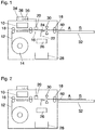
- a printer according to the invention comprises an image forming station 10 arranged to form an image on a media that takes the form of an endless web 12 and is withdrawn from a roll 14.
- a first media transport path 16 is arranged to transport the web past the image forming station 10 and comprises pairs of feed rollers 18 which may be driven to move the web 12 either in a forward direction A or a rearward direction B.
- An image inspection device 20 comprises a camera that is disposed at the media transport path 16 in a position downstream of the image forming station 10 so as to inspect an image that has just been printed onto the web in the image forming station 10.
- a second media transport path 22 is arranged to branch off from the first media transport path 16 at a switch 24 and contains a shredder 26 and a reject bin 28 constituting a reject port of the printer.
- a cutting device 30 is arranged at the first media transport path 16 in a position downstream of the switch 24 and serves for cutting the web 12 into separate sheets.
- the web 12 In a normal mode of operation of the printer the web 12 is moved in the forward direction A and images are printed on successive portions of the web by means of the image forming station 10.
- the web 12 When a trailing edge of a printed image reaches the position of the cutting device 30, the web 12 is cut (possibly with temporary interruption of the movement of the web), and then the cut sheet carrying the printed image is conveyed to an output port 32 of the printer, the output port being constituted by a tray, for example.
- the image forming station 10 has a page-wide print head which extends over the entire width of the web 12 (in the direction normal to the plane of the drawing in Fig. 1 ). This permits to operate the printer in a highly productive single-pass mode in which each portion of the web 12 is moved past the image forming station 10 only once.
- the image forming station 10 may be an ink jet printer, and a malfunction may consist in one or more nozzles of the print head becoming clogged. The resulting artefact will be a number of missing lines (in lengthwise direction of the web) in the printed image.
- the web 12 is conveyed further in the forward direction A until the trailing edge of the printed part 40 of the image reaches the position of the cutting device 30, as has been shown in Fig. 2 .
- the feed rollers 18 may be controlled to convey the web 12 over that known distance.
- the image inspection device 20 may be used for checking the advance of the web by detecting the time at which the trailing edge of the printed part 40 of the image passes the inspection device.
- the cutting device 30 is actuated for cutting the sheet. Then, the upstream part of the web 12 is transported in reverse direction until the new leading edge of the web which has just been produced by the cutting device reaches again the print position at the image forming station 10. This condition of the web 12 has been illustrated in Fig. 3 .
- the controller 34 will command a maintenance cycle to be performed for the image forming station 10 in order to clean the print head and thereby to remove the cause for the artefacts.
- the maintenance cycle has been completed and the rejected sheet has been shredded completely and therefore has left the first media transport path 16, the print process may be resumed with printing a new copy of the image that has been rejected.
- the cutting device 30 might also be provided on the upstream side of the image forming station 10 in a modified embodiment. In that case, the images would be printed on sheets that have already been cut from the web 12. However, the length of the cut sheet would then be fixed already at the time when an artefact is detected by the inspection device 20. Consequently, the entire cut sheet would have to be rejected and the waste could not be reduced by stopping the print process immediately when the artefact is detected. It is therefore preferred that the cutting device 30 is provided on the downstream side of the image forming station 10.
- the image inspection device 20 is disposed as closely as possible to the image forming station 10 so that artefacts can be detected with only a little delay and the print process can be aborted early.
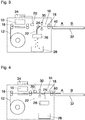
- Figs. 4 to 6 illustrate a modified embodiment in which the orientation of the switch 24 and the sequence of the cutting device 30 and the switch 24 have been reversed.
- Fig. 4 illustrates again the moment at which the artefact is detected and the print process is aborted.
- the direction of transport of the web 12 is reversed and the web is withdrawn to the position shown in Fig. 5 , i.e. a position where the leading edge of the web (in forward direction) is upstream of the switch 24.
- the switch 24 is actuated and the direction of transport of the web 12 is reversed again so that the web will be deflected into the second media transport part 22 and the leading portion of the web will be shredded, as shown in Fig. 6 .
- the cutting device When the trailing edge of the printed part 40 has reached the position of the cutting device 30, the cutting device is actuated for cutting the web. While the rest of the cut sheet will be shredded, the main part of the web 12 will be withdrawn until the leading edge has again reached the print position at the image forming station 10, so that a new print process may start for recovering the rejected image.
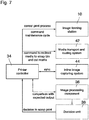
- Fig. 7 is a block diagram showing the essential components of a printer according to the invention and its control system.
- the controller 34 controls the operation of the image forming station 10 as well as the operations of a media transport and routing system 42 which comprises among others the feed rollers 18, the cutting device 30, the switch 24 and the shredder 26.
- An inline image capturing system 44 (camera) constitutes the sensor part of the image inspection device 20 and operates in synchronism with the operations of the printer as controlled by the controller 34.
- image processing component 36 and the decision unit 38 have been shown here as separate blocks, although these components may in practice be integrated in the controller 34.
- the decision unit 38 When, by comparing the captured image with the expected output, the image processing component 36 detects an artefact, the decision unit 38 is activated to decide whether the artefact is tolerable or leads to a rejection of the print. In the latter case, a signal that the print shall be rejected and scrapped is sent to the controller 34, which thereupon cancels the print process and then controls the media transport and routing system 42 so as to redirect the media to be scrapped into the second media transport path 22 and to separate it from the main web appropriately. Further, the controller 34 commands a maintenance cycle for the image forming station, so that the printer will be ready for printing again without producing artefacts.
Landscapes
- Engineering & Computer Science (AREA)
- Physics & Mathematics (AREA)
- General Physics & Mathematics (AREA)
- Mechanical Engineering (AREA)
- Microelectronics & Electronic Packaging (AREA)
- Food Science & Technology (AREA)
- Quality & Reliability (AREA)
- Handling Of Sheets (AREA)
- Separation, Sorting, Adjustment, Or Bending Of Sheets To Be Conveyed (AREA)
- Controlling Sheets Or Webs (AREA)
Description
- The invention relates to a printer comprising:
- an image forming station;
- a first media transport path arranged to convey printed media from the image forming station to an output port;
- a second media transport path branching off from the first media transport path and arranged to convey printed media to a reject port;
- a switch for directing printed media into the second media transport path;
- an image inspection device for inspecting images printed onto the media; and
- a decision unit arranged to decide, on the basis of an inspection result obtained from the image inspection device, whether a printed image shall be rejected, and arranged to control the switch.
-
US 2011/075 193 A1 discloses a cut-sheet printer which has the features listed above.US2004/0165928 A1 discloses a roll-to-sheet printer with sensors to detect a state of a document in the printing system and a delivery device to direct document not retrieved in a timely manner to a waste receptacle. - It is an object of the invention to provide a roll-to-sheet printer which is capable of automatically separating defective prints from acceptable prints and which has a compact design.
- In order to achieve this object, the printer according to the invention is characterized in that:
- the printer is a roll-to-sheet printer having a roll from which the media are supplied into the first media transport path in the form of an endless web, the printer comprising a cutting device for cutting the web;
- the decision unit is arranged to cause a reversal of the transport direction of the media in the first media transport path, thereby to move an edge of the printed media to the position of the switch; and wherein:
- the image inspection device is arranged downstream of the image forming station and upstream of the output port; and
- the switch is arranged to deflect media that move in the first media transport path in a reverse direction into the second media transport path.
- The problem with roll-to-sheet printers is that the printed images, since they are printed on an endless web, may have considerably large dimensions in the media transport direction. Since a decision whether or not a printed image shall be rejected because of artefacts contained in the image can be taken only after the last pixel line of the image has been inspected, a conventional design would require that the switch is disposed at a sufficiently large distance from the image inspection device so that the web carrying the printed image or, if the web has been cut already, the sheet carrying the printed image can still be directed into the second media transport path at the switch. The invention solves this problem by reversing the transport direction of the media in the first media transport path. This permits to arrange the switch in close proximity to the image inspection device and to allow for situations in which a leading edge of the web or sheet has passed the switch already when an artefact is detected and is decided that the print should be discarded. In such a situation, the web or sheet will be moved in the direction opposite to the original transport direction until an edge of the web or sheet has been returned to the position of the switch, so that the switch may direct to the web or sheet into the second media transport path leading to the reject port.
- More specific optional features of the invention are indicated in the dependent claims.
- It will be appreciated that the present invention may be applied to any type of roll-to-sheet printer, regardless of the type image forming station applied, as artifacts in the print media occur for any type of image forming station, for example print artifacts, transport artifacts, alignments artifacts, specifically wrinkles, tears, banding of the printed image or swaths thereof, and/or misalignment of the printed image on the media. Preferably, the printing system is an inkjet roll-to-sheet printing system, but the present invention may be applied to roll-to-sheet printing systems with other image forming stations such as toner-based systems.
- In an embodiment, the switch is arranged to deflect media that move in the first media transport path in a reverse direction into the second media transport path after a trailing edge of said media has passed the switch in the transport direction. Thereby, the media is directed to the output port onto the output tray. From the output tray, the media may be reversed into the second transport path with the former trailing edge as the present leading edge of the media. As such, the output tray is utilized for temporarily holding or supporting the media while the media is sensed by the image inspection device. The length of the transport path of the printing system may thus be relatively compact.
- In an embodiment, the image inspection device is arranged downstream of the image forming station and upstream of the switch. This allows for an even more compact embodiment.
- In a further embodiment, the switch is arranged downstream of the image forming station and upstream of the output port. The media may thus be reversed from the output tray onto the second transport path. Both the image inspection device and the switch may thus be positioned relatively near the image forming station.
- In another embodiment, the printing system according to the present invention further comprises a controller configured for:
- transporting printed media in the transport direction over the first media transport path until a trailing edge of the media passes the switch;
- when the decision unit causes a reversal of the transport direction of the media in the first media transport path, controlling the switch to direct said edge of the media in the reverse direction via the switch onto the second media transport path. The controller first transports the media in the transport direction over the first transport path until the trailing edge passes the switch. The trailing edge also passes the image inspection device, such that the printed image may be inspected in full or completely (though the inspection may be terminated earlier when a critical artifact has been detected). The decision unit then decides on the quality of the printed image. If deemed unsuitable, the switch is controlled to direct the media from the output tray into the second transport path by reversing the direction of the media. The trailing edge therein becomes the leading edge which leads the media past the switch into the second transport path.
- In one embodiment the switch may be arranged to deflect the media into the second media transport path when the media moves in reverse direction. In that case the part of the web carrying the printed image is cut when a defect in the printed image has been detected. Thereafter, the cut sheet is moved in the reverse direction and the switch will direct it into the reject port.
- In another embodiment the switch may be arranged to deflect the media into the second media transport path when the media moves in the regular transport direction. In that case, when a defect is detected, the web or sheet is at first moved in the reverse direction until the leading edge of the web or sheet has reached again a position upstream of the switch. Then, when the media is again moved in forward direction, the switch will deflect it towards the reject port.
- The cutting device for cutting the web may be arranged upstream or downstream of the image forming station. It is preferred that the cutting device is disposed downstream of the image forming station so as to cut the web only after an image has been printed. In that case, when it is decided that a print shall be rejected, the print process may be stopped immediately and the cutting device may be used to cut-off only the length of the web on which a part of the image had been printed until the defect was detected. This will reduce the amount of waste produced when images are rejected. In another embodiment, the cutting device may provided upstream of the image forming unit, e.g. in or near a web feeding unit holding the roll.
- The second media transport path may contain a shredder for immediately shredding the rejected images.
- Embodiment examples will now be described in conjunction with the drawings, wherein:
- Figs. 1 to 3
- are schematic views of a printer according to the invention in different operational states;
- Figs. 4 to 6
- are views analogous to
Figs. 1 to 3 and show another embodiment of the invention; and - Fig. 7
- is a block diagram illustrating the operation of a printer according to the invention.
- As is shown in
Fig. 1 , a printer according to the invention comprises animage forming station 10 arranged to form an image on a media that takes the form of anendless web 12 and is withdrawn from aroll 14. A firstmedia transport path 16 is arranged to transport the web past theimage forming station 10 and comprises pairs offeed rollers 18 which may be driven to move theweb 12 either in a forward direction A or a rearward direction B. - An
image inspection device 20 comprises a camera that is disposed at themedia transport path 16 in a position downstream of theimage forming station 10 so as to inspect an image that has just been printed onto the web in theimage forming station 10. - A second
media transport path 22 is arranged to branch off from the firstmedia transport path 16 at aswitch 24 and contains ashredder 26 and areject bin 28 constituting a reject port of the printer. - A
cutting device 30 is arranged at the firstmedia transport path 16 in a position downstream of theswitch 24 and serves for cutting theweb 12 into separate sheets. - In a normal mode of operation of the printer the
web 12 is moved in the forward direction A and images are printed on successive portions of the web by means of theimage forming station 10. When a trailing edge of a printed image reaches the position of the cuttingdevice 30, theweb 12 is cut (possibly with temporary interruption of the movement of the web), and then the cut sheet carrying the printed image is conveyed to anoutput port 32 of the printer, the output port being constituted by a tray, for example. - In this example, the
image forming station 10 has a page-wide print head which extends over the entire width of the web 12 (in the direction normal to the plane of the drawing inFig. 1 ). This permits to operate the printer in a highly productive single-pass mode in which each portion of theweb 12 is moved past theimage forming station 10 only once. However, in case of a malfunction of theimage forming station 10, there is no possibility to correct any artefacts that the malfunction may have produced in the printed image. For example, theimage forming station 10 may be an ink jet printer, and a malfunction may consist in one or more nozzles of the print head becoming clogged. The resulting artefact will be a number of missing lines (in lengthwise direction of the web) in the printed image. - The
inspection device 20 is provided for automatically detecting such artefacts by comparing an image captured from theweb 12 by means of the camera to a reference image that is stored in acontroller 34 of the printer and from which the print instructions for theimage forming station 10 have been derived. To that end, thecontroller 34 comprises animage processing component 36 and adecision unit 38 which decides whether the detected artefacts are still acceptable or whether they are so severe that the printed image should be rejected. - In
Fig. 1 , a portion of aweb 12 on which apart 40 of an image has already been printed is designated by a broken line. Thepart 40 of the image extends from a leading edge of the web 12 (already on the tray forming the output port 32) to the position of theimage forming station 10. It shall now be assumed that, in the very moment that has been depicted inFig. 1 , theinspection device 20 detects a severe artefact and thedecision unit 38 decides that the image shall be rejected. Thereupon thecontroller 34 immediately aborts the print process, although the printed image is not jet complete. Since the part of the web that carries the rejected image will be discarded, the immediate abortion of the print process avoids the production of unnecessary waste. - Then, under the control of the
controller 34, theweb 12 is conveyed further in the forward direction A until the trailing edge of the printedpart 40 of the image reaches the position of the cuttingdevice 30, as has been shown inFig. 2 . Since the distance between the print position of theimage forming station 10 and the position of the cuttingdevice 30 is known, thefeed rollers 18 may be controlled to convey theweb 12 over that known distance. Optionally, theimage inspection device 20 may be used for checking the advance of the web by detecting the time at which the trailing edge of the printedpart 40 of the image passes the inspection device. - In the situation shown in
Fig. 2 , the cuttingdevice 30 is actuated for cutting the sheet. Then, the upstream part of theweb 12 is transported in reverse direction until the new leading edge of the web which has just been produced by the cutting device reaches again the print position at theimage forming station 10. This condition of theweb 12 has been illustrated inFig. 3 . - The withdrawal of the web has produced a gap between the
web 12 and the cut sheet bearing thepart 40 of the printed image. This gap exists in particular at the position of theswitch 24 which can therefore be pivoted into the position shown inFig. 3 . Then, thefeed rollers 18 at the downstream side of the firstmedia transport path 16 are driven to move the cut sheet in the reverse direction B. Consequently, the edge of the cut sheet which is now the leading edge (due to the reversal of the direction of movement) will be deflected at theswitch 24 into the secondmedia transport path 22 where the sheet is shredded with theshredder 26 and the shreds are collected in thereject bin 28. - Meanwhile, the
controller 34 will command a maintenance cycle to be performed for theimage forming station 10 in order to clean the print head and thereby to remove the cause for the artefacts. When the maintenance cycle has been completed and the rejected sheet has been shredded completely and therefore has left the firstmedia transport path 16, the print process may be resumed with printing a new copy of the image that has been rejected. - Since information about the length of an image to be printed is available in the
controller 34, the cuttingdevice 30 might also be provided on the upstream side of theimage forming station 10 in a modified embodiment. In that case, the images would be printed on sheets that have already been cut from theweb 12. However, the length of the cut sheet would then be fixed already at the time when an artefact is detected by theinspection device 20. Consequently, the entire cut sheet would have to be rejected and the waste could not be reduced by stopping the print process immediately when the artefact is detected. It is therefore preferred that the cuttingdevice 30 is provided on the downstream side of theimage forming station 10. - For the same reason, it is preferred that the
image inspection device 20 is disposed as closely as possible to theimage forming station 10 so that artefacts can be detected with only a little delay and the print process can be aborted early. In principle, it would also be possible, however, to arrange theinspection device 20 downstream of theswitch 24 or even downstream of the cuttingdevice 30. -
Figs. 4 to 6 illustrate a modified embodiment in which the orientation of theswitch 24 and the sequence of the cuttingdevice 30 and theswitch 24 have been reversed. -
Fig. 4 illustrates again the moment at which the artefact is detected and the print process is aborted. At this instant, the direction of transport of theweb 12 is reversed and the web is withdrawn to the position shown inFig. 5 , i.e. a position where the leading edge of the web (in forward direction) is upstream of theswitch 24. Then, theswitch 24 is actuated and the direction of transport of theweb 12 is reversed again so that the web will be deflected into the secondmedia transport part 22 and the leading portion of the web will be shredded, as shown inFig. 6 . - When the trailing edge of the printed
part 40 has reached the position of the cuttingdevice 30, the cutting device is actuated for cutting the web. While the rest of the cut sheet will be shredded, the main part of theweb 12 will be withdrawn until the leading edge has again reached the print position at theimage forming station 10, so that a new print process may start for recovering the rejected image. -
Fig. 7 is a block diagram showing the essential components of a printer according to the invention and its control system. Thecontroller 34 controls the operation of theimage forming station 10 as well as the operations of a media transport androuting system 42 which comprises among others thefeed rollers 18, the cuttingdevice 30, theswitch 24 and theshredder 26. An inline image capturing system 44 (camera) constitutes the sensor part of theimage inspection device 20 and operates in synchronism with the operations of the printer as controlled by thecontroller 34. - For the sake of clarity, the
image processing component 36 and thedecision unit 38 have been shown here as separate blocks, although these components may in practice be integrated in thecontroller 34. - When, by comparing the captured image with the expected output, the
image processing component 36 detects an artefact, thedecision unit 38 is activated to decide whether the artefact is tolerable or leads to a rejection of the print. In the latter case, a signal that the print shall be rejected and scrapped is sent to thecontroller 34, which thereupon cancels the print process and then controls the media transport androuting system 42 so as to redirect the media to be scrapped into the secondmedia transport path 22 and to separate it from the main web appropriately. Further, thecontroller 34 commands a maintenance cycle for the image forming station, so that the printer will be ready for printing again without producing artefacts.
Claims (8)
- A printer comprising:- an image forming station (10);- a first media transport path (16) arranged to convey printed media from the image forming station (10) to an output port (32);- a second media transport path (22) branching off from the first media transport path (16) and arranged to convey printed media to a reject port (26, 28);- a switch (24) for directing printed media into the second media transport path (22);- an image inspection device (20) for inspecting images printed onto the media; and- a decision unit (38) arranged to decide, on the basis of an inspection result obtained from the image inspection device, whether a printed image shall be rejected, and arranged to control the switch (24);- the printer is a roll-to-sheet printer having a roll (14) from which the media are supplied into the first media support path (16) in the form of an endless web (12), the printer comprising a cutting device (30) for cutting the web; and- the decision unit (38) is arranged to cause a reversal of the transport direction (A, B) of the media in the first media transport path (16), thereby to move an edge of the printed media to the position of the switch (24);characterized in that:the image inspection device (20) is arranged downstream of the image forming station (10) and upstream of the output port (32); andthe switch (24) is arranged to deflect media that move in the first media transport path in a reverse direction (B) into the second media transport path (22).
- The printer according to claim 1, wherein the image inspection device (20) is arranged downstream of the image forming station (10) and upstream of the switch (24).
- The printer according to any of the previous claims, wherein the switch (24) is arranged to deflect media that move in the first media transport path in a reverse direction (B) into the second media transport path (22) after a trailing edge of said media has passed the switch (24) in the transport direction (A).
- The printer according to any of the previous claims, wherein the switch (24) is arranged downstream of the image forming station (10) and upstream of the output port (32).
- The printer according to any of the previous claims, wherein a shredder (26) is arranged in the second media transport path (22).
- The printer according to any of the previous claims, wherein the cutting device (30) is arranged downstream of the image forming station (10).
- The printer according to any of the previous claims, wherein the switch (24) is arranged to deflect media that move in the first media transport path (16) in a forward direction (A) into the second media transport path (22), and the cutting device (30) is disposed upstream of the switch (24).
- The printer according to any of the previous claims, further comprising a controller (34) configured for:- transporting printed media in the transport direction (A) over the first media transport path (16) until a trailing edge of the media passes the switch (24);- when the decision unit (38) causes a reversal of the transport direction (A) of the media in the first media transport path (16), controlling the switch (24) to direct said edge of the media in the reverse direction (B) via the switch (24) onto the second media transport path (22).
Applications Claiming Priority (1)
| Application Number | Priority Date | Filing Date | Title |
|---|---|---|---|
| EP16204625 | 2016-12-16 |
Publications (2)
| Publication Number | Publication Date |
|---|---|
| EP3335894A1 EP3335894A1 (en) | 2018-06-20 |
| EP3335894B1 true EP3335894B1 (en) | 2019-10-16 |
Family
ID=57570367
Family Applications (1)
| Application Number | Title | Priority Date | Filing Date |
|---|---|---|---|
| EP17206380.2A Not-in-force EP3335894B1 (en) | 2016-12-16 | 2017-12-11 | Printer with image inspection device |
Country Status (2)
| Country | Link |
|---|---|
| US (1) | US20180170077A1 (en) |
| EP (1) | EP3335894B1 (en) |
Families Citing this family (9)
| Publication number | Priority date | Publication date | Assignee | Title |
|---|---|---|---|---|
| EP3441872B1 (en) * | 2017-08-09 | 2023-02-22 | Canon Production Printing Holding B.V. | Roll-fed printing apparatus, software medium, and method for controlling a roll-fed printing apparatus |
| WO2019117897A1 (en) * | 2017-12-13 | 2019-06-20 | Hewlett-Packard Development Company, L.P. | Buffer unit |
| JP7102293B2 (en) * | 2018-08-30 | 2022-07-19 | 理想科学工業株式会社 | Image inspection equipment |
| DE102019103156A1 (en) * | 2019-02-08 | 2020-08-13 | Bundesdruckerei Gmbh | Device and method for printing on a print substrate |
| JP7549465B2 (en) * | 2020-06-04 | 2024-09-11 | キヤノン株式会社 | Printing system, inspection method, and program |
| NL2026664B1 (en) | 2020-10-13 | 2022-06-08 | Canon Production Printing Holding Bv | A method of handling and inspecting sheets in a sheet processing system |
| JP7562462B2 (en) * | 2021-03-24 | 2024-10-07 | 株式会社Screenホールディングス | Printing device and printing system |
| JP7729176B2 (en) * | 2021-10-27 | 2025-08-26 | 株式会社リコー | Conveying device, printing device, liquid ejecting device |
| CN122230852A (en) * | 2024-12-18 | 2026-06-19 | 金宝电子工业股份有限公司 | Multifunctional Transaction Machine and its Operating Method |
Family Cites Families (10)
| Publication number | Priority date | Publication date | Assignee | Title |
|---|---|---|---|---|
| US5745217A (en) * | 1996-03-29 | 1998-04-28 | Eastman Kodak Company | System for detecting, coding, avoiding, and removing defects on a photosensitive web |
| US7048457B2 (en) * | 2003-02-24 | 2006-05-23 | International Business Machines Corporation | Document delivery system apparatus and method |
| CH696527A5 (en) * | 2003-05-16 | 2007-07-31 | Bobst Sa | A method of quality control of flat elements and device for implementing this method. |
| JP4540471B2 (en) * | 2004-12-27 | 2010-09-08 | 株式会社サトー | Tag printer with stacker |
| US20080232827A1 (en) * | 2007-03-22 | 2008-09-25 | Kabushiki Kaisha Toshiba | Image forming apparatus and image forming method |
| JP2010091652A (en) * | 2008-10-06 | 2010-04-22 | Konica Minolta Business Technologies Inc | Image forming apparatus |
| US8384963B2 (en) | 2009-09-29 | 2013-02-26 | Konica Minolta Laboratory U.S.A., Inc. | System and method for monitoring output of printing devices |
| US8791971B2 (en) * | 2012-07-12 | 2014-07-29 | Eastman Kodak Company | Large-particle inkjet dual-sign development printing |
| JP6217329B2 (en) * | 2013-11-11 | 2017-10-25 | 株式会社リコー | Inspection apparatus, image forming apparatus, inspection method, and program |
| DE102015203931A1 (en) * | 2015-03-05 | 2016-09-08 | Heidelberger Druckmaschinen Ag | Method for register correction of a flatbed punching machine |
-
2017
- 2017-12-06 US US15/833,657 patent/US20180170077A1/en not_active Abandoned
- 2017-12-11 EP EP17206380.2A patent/EP3335894B1/en not_active Not-in-force
Non-Patent Citations (1)
| Title |
|---|
| None * |
Also Published As
| Publication number | Publication date |
|---|---|
| US20180170077A1 (en) | 2018-06-21 |
| EP3335894A1 (en) | 2018-06-20 |
Similar Documents
| Publication | Publication Date | Title |
|---|---|---|
| EP3335894A1 (en) | Printer with image inspection device | |
| JP4999962B2 (en) | Printing apparatus and printing method | |
| CN1278867C (en) | Printing apparatus and control method thereof | |
| JP4979785B2 (en) | Printing apparatus and jam recovery method in printing apparatus | |
| CN102673187B (en) | Recording medium cutting apparatus | |
| US9102143B2 (en) | Method of setting maintenance regions posterior to unavailable printing regions in duplex printer | |
| JP5911256B2 (en) | Printing apparatus and inspection method | |
| JP5312639B2 (en) | Printing apparatus and control method thereof | |
| JP5225907B2 (en) | Printing system and printing apparatus | |
| US10594883B2 (en) | Image forming system | |
| EP2112112B1 (en) | Paper Folding Device And Image Forming Apparatus | |
| JP6376775B2 (en) | Sheet conveying apparatus, sheet cutting apparatus, and image forming apparatus | |
| JP2015139891A (en) | Printing control apparatus, printing apparatus, and printing method | |
| JP2008110554A (en) | Printer | |
| US20220321732A1 (en) | Image Recording Device, Method of Controlling Image Recording Device, and Non-Transitory Computer-Readable Recording Medium Therefor | |
| JP2006282349A (en) | Image forming apparatus | |
| JP6249823B2 (en) | Sheet conveying apparatus, sheet cutting apparatus, and image forming apparatus | |
| JP7340074B2 (en) | Recording device and its control method | |
| JP4789633B2 (en) | Feeding and conveying control method and image forming apparatus | |
| JP4781134B2 (en) | Printing device | |
| JP6615278B2 (en) | Printing device | |
| JP2002036671A (en) | Serial printer | |
| JP6004813B2 (en) | Control method of printing apparatus, continuous sheet and printing apparatus | |
| JP6408782B2 (en) | Recording apparatus and recording method | |
| JP4905236B2 (en) | Image reading apparatus and image forming apparatus |
Legal Events
| Date | Code | Title | Description |
|---|---|---|---|
| PUAI | Public reference made under article 153(3) epc to a published international application that has entered the european phase |
Free format text: ORIGINAL CODE: 0009012 |
|
| STAA | Information on the status of an ep patent application or granted ep patent |
Free format text: STATUS: THE APPLICATION HAS BEEN PUBLISHED |
|
| AK | Designated contracting states |
Kind code of ref document: A1 Designated state(s): AL AT BE BG CH CY CZ DE DK EE ES FI FR GB GR HR HU IE IS IT LI LT LU LV MC MK MT NL NO PL PT RO RS SE SI SK SM TR |
|
| AX | Request for extension of the european patent |
Extension state: BA ME |
|
| STAA | Information on the status of an ep patent application or granted ep patent |
Free format text: STATUS: REQUEST FOR EXAMINATION WAS MADE |
|
| 17P | Request for examination filed |
Effective date: 20181220 |
|
| RBV | Designated contracting states (corrected) |
Designated state(s): AL AT BE BG CH CY CZ DE DK EE ES FI FR GB GR HR HU IE IS IT LI LT LU LV MC MK MT NL NO PL PT RO RS SE SI SK SM TR |
|
| GRAP | Despatch of communication of intention to grant a patent |
Free format text: ORIGINAL CODE: EPIDOSNIGR1 |
|
| STAA | Information on the status of an ep patent application or granted ep patent |
Free format text: STATUS: GRANT OF PATENT IS INTENDED |
|
| INTG | Intention to grant announced |
Effective date: 20190522 |
|
| GRAS | Grant fee paid |
Free format text: ORIGINAL CODE: EPIDOSNIGR3 |
|
| GRAA | (expected) grant |
Free format text: ORIGINAL CODE: 0009210 |
|
| STAA | Information on the status of an ep patent application or granted ep patent |
Free format text: STATUS: THE PATENT HAS BEEN GRANTED |
|
| AK | Designated contracting states |
Kind code of ref document: B1 Designated state(s): AL AT BE BG CH CY CZ DE DK EE ES FI FR GB GR HR HU IE IS IT LI LT LU LV MC MK MT NL NO PL PT RO RS SE SI SK SM TR |
|
| REG | Reference to a national code |
Ref country code: GB Ref legal event code: FG4D |
|
| REG | Reference to a national code |
Ref country code: CH Ref legal event code: EP |
|
| REG | Reference to a national code |
Ref country code: IE Ref legal event code: FG4D |
|
| REG | Reference to a national code |
Ref country code: DE Ref legal event code: R096 Ref document number: 602017007860 Country of ref document: DE |
|
| REG | Reference to a national code |
Ref country code: AT Ref legal event code: REF Ref document number: 1190907 Country of ref document: AT Kind code of ref document: T Effective date: 20191115 |
|
| REG | Reference to a national code |
Ref country code: NL Ref legal event code: FP |
|
| REG | Reference to a national code |
Ref country code: LT Ref legal event code: MG4D |
|
| REG | Reference to a national code |
Ref country code: AT Ref legal event code: MK05 Ref document number: 1190907 Country of ref document: AT Kind code of ref document: T Effective date: 20191016 |
|
| PG25 | Lapsed in a contracting state [announced via postgrant information from national office to epo] |
Ref country code: LV Free format text: LAPSE BECAUSE OF FAILURE TO SUBMIT A TRANSLATION OF THE DESCRIPTION OR TO PAY THE FEE WITHIN THE PRESCRIBED TIME-LIMIT Effective date: 20191016 Ref country code: SE Free format text: LAPSE BECAUSE OF FAILURE TO SUBMIT A TRANSLATION OF THE DESCRIPTION OR TO PAY THE FEE WITHIN THE PRESCRIBED TIME-LIMIT Effective date: 20191016 Ref country code: AT Free format text: LAPSE BECAUSE OF FAILURE TO SUBMIT A TRANSLATION OF THE DESCRIPTION OR TO PAY THE FEE WITHIN THE PRESCRIBED TIME-LIMIT Effective date: 20191016 Ref country code: FI Free format text: LAPSE BECAUSE OF FAILURE TO SUBMIT A TRANSLATION OF THE DESCRIPTION OR TO PAY THE FEE WITHIN THE PRESCRIBED TIME-LIMIT Effective date: 20191016 Ref country code: PT Free format text: LAPSE BECAUSE OF FAILURE TO SUBMIT A TRANSLATION OF THE DESCRIPTION OR TO PAY THE FEE WITHIN THE PRESCRIBED TIME-LIMIT Effective date: 20200217 Ref country code: BG Free format text: LAPSE BECAUSE OF FAILURE TO SUBMIT A TRANSLATION OF THE DESCRIPTION OR TO PAY THE FEE WITHIN THE PRESCRIBED TIME-LIMIT Effective date: 20200116 Ref country code: LT Free format text: LAPSE BECAUSE OF FAILURE TO SUBMIT A TRANSLATION OF THE DESCRIPTION OR TO PAY THE FEE WITHIN THE PRESCRIBED TIME-LIMIT Effective date: 20191016 Ref country code: GR Free format text: LAPSE BECAUSE OF FAILURE TO SUBMIT A TRANSLATION OF THE DESCRIPTION OR TO PAY THE FEE WITHIN THE PRESCRIBED TIME-LIMIT Effective date: 20200117 Ref country code: PL Free format text: LAPSE BECAUSE OF FAILURE TO SUBMIT A TRANSLATION OF THE DESCRIPTION OR TO PAY THE FEE WITHIN THE PRESCRIBED TIME-LIMIT Effective date: 20191016 Ref country code: NO Free format text: LAPSE BECAUSE OF FAILURE TO SUBMIT A TRANSLATION OF THE DESCRIPTION OR TO PAY THE FEE WITHIN THE PRESCRIBED TIME-LIMIT Effective date: 20200116 |
|
| PG25 | Lapsed in a contracting state [announced via postgrant information from national office to epo] |
Ref country code: HR Free format text: LAPSE BECAUSE OF FAILURE TO SUBMIT A TRANSLATION OF THE DESCRIPTION OR TO PAY THE FEE WITHIN THE PRESCRIBED TIME-LIMIT Effective date: 20191016 Ref country code: RS Free format text: LAPSE BECAUSE OF FAILURE TO SUBMIT A TRANSLATION OF THE DESCRIPTION OR TO PAY THE FEE WITHIN THE PRESCRIBED TIME-LIMIT Effective date: 20191016 Ref country code: IS Free format text: LAPSE BECAUSE OF FAILURE TO SUBMIT A TRANSLATION OF THE DESCRIPTION OR TO PAY THE FEE WITHIN THE PRESCRIBED TIME-LIMIT Effective date: 20200224 |
|
| PG25 | Lapsed in a contracting state [announced via postgrant information from national office to epo] |
Ref country code: AL Free format text: LAPSE BECAUSE OF FAILURE TO SUBMIT A TRANSLATION OF THE DESCRIPTION OR TO PAY THE FEE WITHIN THE PRESCRIBED TIME-LIMIT Effective date: 20191016 |
|
| REG | Reference to a national code |
Ref country code: DE Ref legal event code: R097 Ref document number: 602017007860 Country of ref document: DE |
|
| PG2D | Information on lapse in contracting state deleted |
Ref country code: IS |
|
| PG25 | Lapsed in a contracting state [announced via postgrant information from national office to epo] |
Ref country code: RO Free format text: LAPSE BECAUSE OF FAILURE TO SUBMIT A TRANSLATION OF THE DESCRIPTION OR TO PAY THE FEE WITHIN THE PRESCRIBED TIME-LIMIT Effective date: 20191016 Ref country code: CZ Free format text: LAPSE BECAUSE OF FAILURE TO SUBMIT A TRANSLATION OF THE DESCRIPTION OR TO PAY THE FEE WITHIN THE PRESCRIBED TIME-LIMIT Effective date: 20191016 Ref country code: ES Free format text: LAPSE BECAUSE OF FAILURE TO SUBMIT A TRANSLATION OF THE DESCRIPTION OR TO PAY THE FEE WITHIN THE PRESCRIBED TIME-LIMIT Effective date: 20191016 Ref country code: EE Free format text: LAPSE BECAUSE OF FAILURE TO SUBMIT A TRANSLATION OF THE DESCRIPTION OR TO PAY THE FEE WITHIN THE PRESCRIBED TIME-LIMIT Effective date: 20191016 Ref country code: DK Free format text: LAPSE BECAUSE OF FAILURE TO SUBMIT A TRANSLATION OF THE DESCRIPTION OR TO PAY THE FEE WITHIN THE PRESCRIBED TIME-LIMIT Effective date: 20191016 Ref country code: IS Free format text: LAPSE BECAUSE OF FAILURE TO SUBMIT A TRANSLATION OF THE DESCRIPTION OR TO PAY THE FEE WITHIN THE PRESCRIBED TIME-LIMIT Effective date: 20200216 |
|
| PLBE | No opposition filed within time limit |
Free format text: ORIGINAL CODE: 0009261 |
|
| STAA | Information on the status of an ep patent application or granted ep patent |
Free format text: STATUS: NO OPPOSITION FILED WITHIN TIME LIMIT |
|
| REG | Reference to a national code |
Ref country code: BE Ref legal event code: MM Effective date: 20191231 |
|
| PG25 | Lapsed in a contracting state [announced via postgrant information from national office to epo] |
Ref country code: SK Free format text: LAPSE BECAUSE OF FAILURE TO SUBMIT A TRANSLATION OF THE DESCRIPTION OR TO PAY THE FEE WITHIN THE PRESCRIBED TIME-LIMIT Effective date: 20191016 Ref country code: MC Free format text: LAPSE BECAUSE OF FAILURE TO SUBMIT A TRANSLATION OF THE DESCRIPTION OR TO PAY THE FEE WITHIN THE PRESCRIBED TIME-LIMIT Effective date: 20191016 Ref country code: SM Free format text: LAPSE BECAUSE OF FAILURE TO SUBMIT A TRANSLATION OF THE DESCRIPTION OR TO PAY THE FEE WITHIN THE PRESCRIBED TIME-LIMIT Effective date: 20191016 Ref country code: IT Free format text: LAPSE BECAUSE OF FAILURE TO SUBMIT A TRANSLATION OF THE DESCRIPTION OR TO PAY THE FEE WITHIN THE PRESCRIBED TIME-LIMIT Effective date: 20191016 |
|
| 26N | No opposition filed |
Effective date: 20200717 |
|
| PG25 | Lapsed in a contracting state [announced via postgrant information from national office to epo] |
Ref country code: LU Free format text: LAPSE BECAUSE OF NON-PAYMENT OF DUE FEES Effective date: 20191211 Ref country code: FR Free format text: LAPSE BECAUSE OF NON-PAYMENT OF DUE FEES Effective date: 20191216 Ref country code: IE Free format text: LAPSE BECAUSE OF NON-PAYMENT OF DUE FEES Effective date: 20191211 |
|
| PG25 | Lapsed in a contracting state [announced via postgrant information from national office to epo] |
Ref country code: SI Free format text: LAPSE BECAUSE OF FAILURE TO SUBMIT A TRANSLATION OF THE DESCRIPTION OR TO PAY THE FEE WITHIN THE PRESCRIBED TIME-LIMIT Effective date: 20191016 Ref country code: BE Free format text: LAPSE BECAUSE OF NON-PAYMENT OF DUE FEES Effective date: 20191231 |
|
| PG25 | Lapsed in a contracting state [announced via postgrant information from national office to epo] |
Ref country code: CY Free format text: LAPSE BECAUSE OF FAILURE TO SUBMIT A TRANSLATION OF THE DESCRIPTION OR TO PAY THE FEE WITHIN THE PRESCRIBED TIME-LIMIT Effective date: 20191016 |
|
| PG25 | Lapsed in a contracting state [announced via postgrant information from national office to epo] |
Ref country code: MT Free format text: LAPSE BECAUSE OF FAILURE TO SUBMIT A TRANSLATION OF THE DESCRIPTION OR TO PAY THE FEE WITHIN THE PRESCRIBED TIME-LIMIT Effective date: 20191016 Ref country code: HU Free format text: LAPSE BECAUSE OF FAILURE TO SUBMIT A TRANSLATION OF THE DESCRIPTION OR TO PAY THE FEE WITHIN THE PRESCRIBED TIME-LIMIT; INVALID AB INITIO Effective date: 20171211 |
|
| REG | Reference to a national code |
Ref country code: CH Ref legal event code: PL |
|
| PG25 | Lapsed in a contracting state [announced via postgrant information from national office to epo] |
Ref country code: CH Free format text: LAPSE BECAUSE OF NON-PAYMENT OF DUE FEES Effective date: 20201231 Ref country code: LI Free format text: LAPSE BECAUSE OF NON-PAYMENT OF DUE FEES Effective date: 20201231 |
|
| PG25 | Lapsed in a contracting state [announced via postgrant information from national office to epo] |
Ref country code: TR Free format text: LAPSE BECAUSE OF FAILURE TO SUBMIT A TRANSLATION OF THE DESCRIPTION OR TO PAY THE FEE WITHIN THE PRESCRIBED TIME-LIMIT Effective date: 20191016 |
|
| PG25 | Lapsed in a contracting state [announced via postgrant information from national office to epo] |
Ref country code: MK Free format text: LAPSE BECAUSE OF FAILURE TO SUBMIT A TRANSLATION OF THE DESCRIPTION OR TO PAY THE FEE WITHIN THE PRESCRIBED TIME-LIMIT Effective date: 20191016 |
|
| GBPC | Gb: european patent ceased through non-payment of renewal fee |
Effective date: 20211211 |
|
| PG25 | Lapsed in a contracting state [announced via postgrant information from national office to epo] |
Ref country code: GB Free format text: LAPSE BECAUSE OF NON-PAYMENT OF DUE FEES Effective date: 20211211 |
|
| PGFP | Annual fee paid to national office [announced via postgrant information from national office to epo] |
Ref country code: NL Payment date: 20231123 Year of fee payment: 7 |
|
| PGFP | Annual fee paid to national office [announced via postgrant information from national office to epo] |
Ref country code: DE Payment date: 20231214 Year of fee payment: 7 |
|
| REG | Reference to a national code |
Ref country code: DE Ref legal event code: R119 Ref document number: 602017007860 Country of ref document: DE |
|
| REG | Reference to a national code |
Ref country code: NL Ref legal event code: MM Effective date: 20250101 |
|
| PG25 | Lapsed in a contracting state [announced via postgrant information from national office to epo] |
Ref country code: NL Free format text: LAPSE BECAUSE OF NON-PAYMENT OF DUE FEES Effective date: 20250101 |
|
| PG25 | Lapsed in a contracting state [announced via postgrant information from national office to epo] |
Ref country code: DE Free format text: LAPSE BECAUSE OF NON-PAYMENT OF DUE FEES Effective date: 20250701 |