EP3335637A1 - Ultrasonic probe - Google Patents
Ultrasonic probe Download PDFInfo
- Publication number
- EP3335637A1 EP3335637A1 EP17160511.6A EP17160511A EP3335637A1 EP 3335637 A1 EP3335637 A1 EP 3335637A1 EP 17160511 A EP17160511 A EP 17160511A EP 3335637 A1 EP3335637 A1 EP 3335637A1
- Authority
- EP
- European Patent Office
- Prior art keywords
- ultrasonic probe
- case
- probe according
- reacting
- indicator
- Prior art date
- Legal status (The legal status is an assumption and is not a legal conclusion. Google has not performed a legal analysis and makes no representation as to the accuracy of the status listed.)
- Granted
Links
Images



Classifications
-
- A—HUMAN NECESSITIES
- A61—MEDICAL OR VETERINARY SCIENCE; HYGIENE
- A61B—DIAGNOSIS; SURGERY; IDENTIFICATION
- A61B8/00—Diagnosis using ultrasonic, sonic or infrasonic waves
- A61B8/44—Constructional features of the ultrasonic, sonic or infrasonic diagnostic device
- A61B8/4422—Constructional features of the ultrasonic, sonic or infrasonic diagnostic device related to hygiene or sterilisation
-
- A—HUMAN NECESSITIES
- A61—MEDICAL OR VETERINARY SCIENCE; HYGIENE
- A61B—DIAGNOSIS; SURGERY; IDENTIFICATION
- A61B8/00—Diagnosis using ultrasonic, sonic or infrasonic waves
- A61B8/44—Constructional features of the ultrasonic, sonic or infrasonic diagnostic device
- A61B8/4477—Constructional features of the ultrasonic, sonic or infrasonic diagnostic device using several separate ultrasound transducers or probes
-
- A—HUMAN NECESSITIES
- A61—MEDICAL OR VETERINARY SCIENCE; HYGIENE
- A61B—DIAGNOSIS; SURGERY; IDENTIFICATION
- A61B8/00—Diagnosis using ultrasonic, sonic or infrasonic waves
- A61B8/44—Constructional features of the ultrasonic, sonic or infrasonic diagnostic device
- A61B8/4411—Device being modular
-
- A—HUMAN NECESSITIES
- A61—MEDICAL OR VETERINARY SCIENCE; HYGIENE
- A61B—DIAGNOSIS; SURGERY; IDENTIFICATION
- A61B8/00—Diagnosis using ultrasonic, sonic or infrasonic waves
- A61B8/44—Constructional features of the ultrasonic, sonic or infrasonic diagnostic device
- A61B8/4444—Constructional features of the ultrasonic, sonic or infrasonic diagnostic device related to the probe
-
- A—HUMAN NECESSITIES
- A61—MEDICAL OR VETERINARY SCIENCE; HYGIENE
- A61B—DIAGNOSIS; SURGERY; IDENTIFICATION
- A61B8/00—Diagnosis using ultrasonic, sonic or infrasonic waves
- A61B8/44—Constructional features of the ultrasonic, sonic or infrasonic diagnostic device
- A61B8/4444—Constructional features of the ultrasonic, sonic or infrasonic diagnostic device related to the probe
- A61B8/4455—Features of the external shape of the probe, e.g. ergonomic aspects
-
- A—HUMAN NECESSITIES
- A61—MEDICAL OR VETERINARY SCIENCE; HYGIENE
- A61L—METHODS OR APPARATUS FOR STERILISING MATERIALS OR OBJECTS IN GENERAL; DISINFECTION, STERILISATION OR DEODORISATION OF AIR; CHEMICAL ASPECTS OF BANDAGES, DRESSINGS, ABSORBENT PADS OR SURGICAL ARTICLES; MATERIALS FOR BANDAGES, DRESSINGS, ABSORBENT PADS OR SURGICAL ARTICLES
- A61L2/00—Disinfection or sterilisation of materials or objects, in general; Accessories therefor
- A61L2/26—Accessories
-
- G—PHYSICS
- G01—MEASURING; TESTING
- G01N—INVESTIGATING OR ANALYSING MATERIALS BY DETERMINING THEIR CHEMICAL OR PHYSICAL PROPERTIES
- G01N21/00—Investigating or analysing materials by the use of optical means, i.e. using sub-millimetre waves, infrared, visible or ultraviolet light
- G01N21/75—Systems in which material is subjected to a chemical reaction, the progress or the result of the reaction being investigated
- G01N21/77—Systems in which material is subjected to a chemical reaction, the progress or the result of the reaction being investigated by observing the effect on a chemical indicator
- G01N21/78—Systems in which material is subjected to a chemical reaction, the progress or the result of the reaction being investigated by observing the effect on a chemical indicator producing a change of colour
-
- G—PHYSICS
- G01—MEASURING; TESTING
- G01N—INVESTIGATING OR ANALYSING MATERIALS BY DETERMINING THEIR CHEMICAL OR PHYSICAL PROPERTIES
- G01N29/00—Investigating or analysing materials by the use of ultrasonic, sonic or infrasonic waves; Visualisation of the interior of objects by transmitting ultrasonic or sonic waves through the object
- G01N29/22—Details, e.g. general constructional or apparatus details
- G01N29/24—Probes
-
- G—PHYSICS
- G01—MEASURING; TESTING
- G01N—INVESTIGATING OR ANALYSING MATERIALS BY DETERMINING THEIR CHEMICAL OR PHYSICAL PROPERTIES
- G01N31/00—Investigating or analysing non-biological materials by the use of the chemical methods specified in the subgroup; Apparatus specially adapted for such methods
- G01N31/22—Investigating or analysing non-biological materials by the use of the chemical methods specified in the subgroup; Apparatus specially adapted for such methods using chemical indicators
-
- A—HUMAN NECESSITIES
- A61—MEDICAL OR VETERINARY SCIENCE; HYGIENE
- A61B—DIAGNOSIS; SURGERY; IDENTIFICATION
- A61B2560/00—Constructional details of operational features of apparatus; Accessories for medical measuring apparatus
- A61B2560/06—Accessories for medical measuring apparatus
-
- A—HUMAN NECESSITIES
- A61—MEDICAL OR VETERINARY SCIENCE; HYGIENE
- A61B—DIAGNOSIS; SURGERY; IDENTIFICATION
- A61B8/00—Diagnosis using ultrasonic, sonic or infrasonic waves
- A61B8/44—Constructional features of the ultrasonic, sonic or infrasonic diagnostic device
- A61B8/4405—Device being mounted on a trolley
-
- A—HUMAN NECESSITIES
- A61—MEDICAL OR VETERINARY SCIENCE; HYGIENE
- A61L—METHODS OR APPARATUS FOR STERILISING MATERIALS OR OBJECTS IN GENERAL; DISINFECTION, STERILISATION OR DEODORISATION OF AIR; CHEMICAL ASPECTS OF BANDAGES, DRESSINGS, ABSORBENT PADS OR SURGICAL ARTICLES; MATERIALS FOR BANDAGES, DRESSINGS, ABSORBENT PADS OR SURGICAL ARTICLES
- A61L2103/00—Materials or objects being the target of disinfection or sterilisation
- A61L2103/15—Laboratory, medical or dentistry appliances, e.g. catheters or sharps
Definitions
- Embodiments of the present disclosure relate to an ultrasonic probe for obtaining an ultrasonic image.
- an ultrasonic imaging apparatus is an apparatus in which an ultrasonic signal is emitted from a surface of an object body toward a target part therein and a tomographic image of soft tissue or an image of a blood flow is obtained without invasiveness using information of a reflected ultrasonic signal (an ultrasonic echo signal).
- the ultrasonic imaging system is smaller and cheaper than other image diagnostic apparatuses such as an X-ray diagnostic apparatus, an X-ray computerized tomography (CT) scanner, a magnetic resonance image (MRI) apparatus and a nuclear medicine diagnostic apparatus, allows an image to be displayed in real time and also has high safety without radiation exposure, it is widely used in a diagnosis of a heart or abdominal area, an urinary system and obstetrical/gynecological diseases.
- CT computerized tomography
- MRI magnetic resonance image
- nuclear medicine diagnostic apparatus allows an image to be displayed in real time and also has high safety without radiation exposure, it is widely used in a diagnosis of a heart or abdominal area, an urinary system and obstetrical/gynecological diseases.
- Such an ultrasonic imaging system includes a probe for emitting the ultrasonic signal and receiving the reflected ultrasonic signal (the ultrasonic echo signal) and a main body for controlling the ultrasonic signal emitted through the probe or generating a necessary image using the received ultrasonic signal.
- an ultrasonic probe including an indicator for previously checking whether a disinfectant or a cleaner is allowed to be used.
- an ultrasonic probe includes a case in which an ultrasonic wave transmitting and receiving device is accommodated; a lens provided at one end of the case; and an indicator attached to an outer surface of the case and including a reacting part configured to react with a certain chemical component.
- the indicator may be disposed adjacent to the lens.
- the indicator may include a plurality of reacting parts, and the plurality of reacting parts may react with chemical components different from each other, respectively.
- the reacting part may include a material of which a color is changed when reacting with a certain chemical component.
- the reacting part may include a material of which the color is changed in stages according to a concentration of the certain chemical material or changed into different color according to the concentration of the certain chemical material.
- the reacting part may include a material disappeared by reacting with a certain chemical component.
- the reacting part may be configured so that a background of a color different from that of the material is exposed when the material is disappeared.
- the indicator may be replaceably attached to the case.
- the indicator may further include an information provider providing information for checking whether the reacting part reacts.
- the information provider may be configured to provide information of a name or a concentration of the certain chemical component with which the reacting part reacts.
- the indicator may include a plurality of reacting parts, and each of the plurality of reacting parts may react according to a concentration of the certain chemical component.
- an ultrasonic probe includes a case in which an ultrasonic wave transmitting and receiving device is accommodated; a lens provided at one end of the case; a cap separably coupled to the case to protect the lens; and an indicator including a reacting part configured to react with a certain chemical component.
- the cap may include a hole or a mesh provided to allow a disinfectant or a cleaner to pass therethrough.
- the indicator may be attached to an outer surface of the cap.
- the indicator may be attached to an outer surface of the case adjacent to the lens.
- the case may include a groove for checking left and right directions of the lens, and the cap includes a hook coupled to the groove.
- the cap may be configured to be spaced apart from the lens at a predetermined distance when being coupled with the case.
- first a first component
- second a second component
- first component a first component without departing from the scope of rights of the disclosure.
- and/or encompasses combinations of a plurality of items or any one of the plurality of items.
- FIG. 1 is a perspective view illustrating a medical apparatus in which an ultrasonic probe according to one embodiment of the present disclosure is allowed to be used.
- a medical apparatus 1 includes a main body 10 and an ultrasonic probe 100 for transmitting an ultrasonic signal to an object to be diagnosed and receiving a signal reflected from the object.
- the ultrasonic probe 100 may be connected to the main body 10 by a cable.
- the ultrasonic probe 100 may be supported at the main body 10 by a holder 22.
- a user may keep the ultrasonic probe 100 in the holder 22 when not using the medical apparatus 1.
- FIG. 1 illustrates a state in which the holder 22 for supporting the ultrasonic probe 100 is provided at a control panel 20.
- the holder 22 may be provided at the main body 10 for the user's convenience.
- the holder 22 may be provided at both of the main body 10 and the control panel 20.
- a moving device 12 for moving the medical apparatus 1 may be provided at the main body 10.
- the moving device 12 may be a plurality of casters provided at a lower surface of the main body 10.
- the casters may be aligned to allow the main body 10 to be moved in a certain direction, may be provided to be freely movable, thereby being movable in any directions or may be locked to be stopped at a certain position.
- the ultrasonic probe 100 includes an ultrasonic wave transmitting and receiving device provided in a case 110.
- the ultrasonic wave transmitting and receiving device may be configured with a transducer module for emitting an ultrasonic wave to the object, receiving an echo ultrasonic wave reflected from the object and mutually converting an electric signal and the ultrasonic wave.
- the ultrasonic probe 100 includes a male connector 130 physically coupled with a female connector 14 of the main body 10 to transmit and receive a signal to/from the main body 10 and a cable 120 for connecting the male connector 130 and the transducer module.
- the object may be a living body of a human being or an animal, or tissues in the living body thereof such as blood vessels, bones and muscles.
- the object is not limited thereto, as long as an image of an internal structure thereof may be taken by the medical apparatus 1, i.e., an ultrasonic imaging system.
- the echo ultrasonic wave is an ultrasonic wave reflected from the object to which the ultrasonic wave is emitted and has a variety of frequency bands or energy intensity for generating various ultrasonic images according to a diagnosis mode.
- the transducer module may generate the ultrasonic wave according to AC power applied thereto.
- the transducer module may receive the AC power from an external power supply or an internal electric condenser, e.g., a battery or the like.
- a vibrator of the transducer module is vibrated according to the applied AC power, and thus the ultrasonic wave may be generated.
- the male connector 130 may be physically coupled to the female connector 14 of the main body 10.
- the male connector 130 serves to transmit an electric signal generated by the transducer module to the female connector 14 physically coupled thereto or to receive a control signal generated by the main body 10 from the female connector 14.
- FIG. 1 illustrates a state in which the male connector 130 and the cable 120 are exposed to an outside.
- the male connector 130 and the cable 120 may be built in a housing forming the main body 10.
- a display 30 and the control panel 20 may be provided at the main body 10 of the medical apparatus 1.
- An input part 24 for allowing the user to control the medical apparatus 1 may be provided at the control panel 20.
- the input part 24 may receive not only setup information about the ultrasonic probe 100 but also various control commands from the user.
- the setup information about the ultrasonic probe 100 includes gain information, zoom information, focus information, time gain compensation (TGC) information, depth information, frequency information, power information, frame average information, dynamic range information and so on.
- TGC time gain compensation
- the setup information about the ultrasonic probe 100 is not limited to one embodiment and may include a variety of information set to take the ultrasonic image.
- the information may be transmitted to the ultrasonic probe 100 through the cable 120, and the ultrasonic probe 100 may be set according to the received information. Furthermore, the main body 10 may receive various control commands like a transmitting command of the ultrasonic signal from the user through the input part 24 and then may transmit the control commands to the ultrasonic probe 100.
- the input part 24 may be realized in a keyboard, foot switch or foot pedal method.
- the keyboard may be realized hardware-wise.
- Such a keyboard may include at least one of a switch, a key, a joystick and a trackball.
- the keyboard may be realized software-wise like a graphic user interface. In this case, the keyboard may be displayed through the display 30.
- the foot switch or the foot pedal may be provided at a lower portion of the main body 10, and the user may control an operation of the medical apparatus 1 using the foot pedal.
- the display 30 may be realized in various well-known methods such as a cathode ray tube (CRT), a liquid crystal display (LCD), a light emitting diode (LED), a plasma display panel (PDP) and an organic light emitting diode (OLED) but is not limited thereto.
- CTR cathode ray tube
- LCD liquid crystal display
- LED light emitting diode
- PDP plasma display panel
- OLED organic light emitting diode
- the display 30 may display the ultrasonic image of a target region in the object.
- the ultrasonic image displayed on the display 30 may be a two-dimensional ultrasonic image or a three-dimensional ultrasonic image, and various ultrasonic images may be displayed according to an operation mode of the medical apparatus 1.
- the display 30 may display not only a menu or guide information required for an ultrasonic diagnosis but also information about an operation state of the ultrasonic probe 100.
- the ultrasonic image includes an A-mode (amplitude mode) image, a B-mode (brightness mode) image and an M-mode (motion mode) image and also includes a C-mode (color mode) image and a D-mode (Doppler mode) image.
- A-mode amplitude mode
- B-mode brightness mode
- M-mode motion mode
- C-mode color mode
- D-mode Doppler mode
- the A-mode image is an ultrasonic image indicating an intensity of an ultrasonic signal corresponding to an echo ultrasonic signal
- the B-mode image is an ultrasonic image indicating the intensity of the ultrasonic signal corresponding to the echo ultrasonic signal into brightness
- the M-mode image is an ultrasonic image indicating a movement of an object at a certain position according to a time.
- the D-mode image is an ultrasonic image indicating the moving object into a waveform using the Doppler effect
- the C-mode image is an ultrasonic image indicating the moving object in the form of a color spectrum.
- a subsidiary display 26 may be provided at the control panel 20.
- the subsidiary display 26 may provide relevant information like a menu or an auxiliary image for optimizing the ultrasonic image, or a graphic interface to the user.
- the subsidiary display 26 when the subsidiary display 26 is realized in a touchscreen type, the display 30 may also perform a function of the input part 24. That is, the main body 10 may receive various commands from the user through at least one of the display 30 and the input part 24. Further, although not shown in the drawings, a voice recognition sensor may be provided at the main body 10 and may receive a voice command from the user.
- FIG. 2 is a perspective view of the ultrasonic probe according to one embodiment of the present disclosure
- FIG. 3 is a view illustrating an indicator attached to the ultrasonic probe illustrated in FIG. 2 .
- the ultrasonic probe 100 includes the case 110 in which the ultrasonic wave transmitting and receiving device, i.e., the transducer module is accommodated and the cable 120 for connecting the ultrasonic wave transmitting and receiving device with the main body 10 of the medical apparatus 1.
- the cable 120 When an inspector uses the ultrasonic probe 100, the cable 120 may be sharply bent or twisted at an end of the case 110 of the ultrasonic probe 100. When the cable 120 is sharply bent or twisted, the cable 120 may be disconnected, or a jacket of the cable 120 may be damaged.
- the ultrasonic probe 100 may include a strain relief 150 provided at the end of the case 110, to which the cable 120 is connected, to cover the cable 120. That is, the strain relief 150 is provided outside one end of the case 110 to prevent a damage of the cable 120.
- the strain relief 150 may be formed of a soft material to allow the cable 120 to be gently curved. Although the strain relief 150 is formed of the soft material, the strain relief 150 should have a predetermined degree of hardness to prevent the cable 120 from being sharply bent. Therefore, the strain relief 150 may have a structure which is easily bent to one side while having the predetermined degree of hardness or a structure which may be bent in multi-stages.
- a lens 140 is disposed at the other end of the case 110 to which the cable 120 is not connected.
- the transducer module disposed inside the case 110 may emit the generated ultrasonic wave to the object through the lens 140. Therefore, in the ultrasonic probe 100, the lens 140 is one of very important components. However, in the ultrasonic probe 100, since the lens 140 is exposed to the outside, it is easy to be damaged due to the user's carelessness.
- the case in which the lens 140 of the ultrasonic probe 100 is damaged includes a case in which the user drops the lens 140 and thus the lens 140 is damaged or scratched, a case in which the lens 140 is neglected while being stained with an ultrasonic diagnosis gel and the ultrasonic diagnosis gel is dried thereon, a case in which the lens 140 is chemically deformed by an unauthorized disinfectant or cleaner, and so on.
- a performance degradation of the ultrasonic probe 100 such as a degradation of resolution, may occur, or a problem such as discoloration and heating may be caused.
- the ultrasonic probe 100 may include an indicator 200 for checking whether the lens 140 is chemically deformed by an unauthorized disinfectant or cleaner.
- the lens 140 When the ultrasonic probe 100 is disinfected or cleaned with the unauthorized disinfectant or cleaner, the lens 140 may be deformed, a separation may occur at a bonded portion, or performance of the transducer module may be degraded due to an internal moisture intrusion.
- the indicator 200 may be attached to one outer surface of the case 110 and may include a reacting part 210 reacting with a certain chemical component.
- the reacting part 210 may be disposed adjacent to the lens 140.
- the reacting part 210 of the indicator 200 may be provided to indicate whether it reacts by a change in a color thereof. That is, the reacting part 210 of the indicator 200 may include a material of which the color is changed by reacting with an unauthorized certain chemical component. Also, the reacting part 210 of the indicator 200 may include a material of which the color is changed in stages or changed into another color according to a concentration of an unauthorized certain chemical material included in the disinfectant, or may include a material of which the color is changed in stages or changed into another color according to a pH concentration of the unauthorized certain chemical material included in the disinfectant.
- the reacting part 210 of the indicator 200 may be provided to indicate whether it reacts by disappearance of the reacting part 210. That is, the reacting part 210 may include a material disappeared by reacting with the unauthorized certain chemical component.
- the reacting part 210 including the material to be disappeared may be configured so that the material to be disappeared is coated on a background having a color different from that of the material to be disappeared and the color of the background is exposed when the material is disappeared.
- an iodine component of povidone as an unauthorized disinfectant is discolored into purple when reacting with starch as a glucose polymer, and a peroxide reacts with catalase, zinc thiophophate and mercaptan, and an ethylene oxide used in the cleaner reacts with ether.
- a kind of acid causing the separation of a layered part in the transducer module reacts with thymol blue, methyl orange, bromothymol blue, phenolphthalein or the like according to a pH concentration thereof and is then discolored.
- the indicator 200 may include a plurality of reacting parts 210 to detect a plurality of unauthorized chemical components.
- Each of the plurality of reacting parts 210 may be provided to react with each of chemical components different from each other. Meanwhile, each of the plurality of reacting parts 210 may be provided to react according to a concentration of a certain chemical component.
- the indicator 200 may include an information provider 220 providing information for checking whether each of the reacting parts 210 reacts. That is, the information provider 220 may provide information for determining or checking whether each of the reacting parts 210 reacts with the certain chemical component.
- the information provider 220 may be configured to provide information of a name or a concentration of the certain chemical component with which each of the reacting parts 210 reacts.
- the information provider 220 may be configured to provide information of a chemical component with which the reacting part 210 among the plurality of reacting parts 210 in which a reactant is discolored or disappeared reacts and the name or the concentration of the reacting chemical component.
- the indicator 200 may be replaceably attached to the case 110 so that the reacting part 210 is replaced after a reaction with the certain chemical component. Meanwhile, when the indicator 200 includes the plurality of reacting parts 210, the indicator 200 may be configured so that only the reacting part 210 reacted with the certain chemical component is replaced.
- FIG. 4 is a perspective view of an ultrasonic probe according to another embodiment of the present disclosure
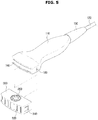
- FIG. 5 is a perspective view illustrating a state in which a cap is separated from the ultrasonic probe illustrated in FIG. 4
- FIG. 6 is a view schematically illustrating a cross section of the ultrasonic probe illustrated in FIG. 4 .
- an ultrasonic probe 101 may include a case 110, a cable 120, a lens 140 and a strain relief 150. Since the case 110, the cable 120, the lens 140 and the strain relief 150 are the same as those described above and illustrated in FIG. 2 , detailed descriptions thereof will be omitted.
- the ultrasonic probe 101 may include a configuration for allowing the inspector to check left and right directions of the lens 140.
- the case 110 may include a groove 160 for checking the left and right directions of the lens 140.
- the groove 160 may be provided at one side surface of the case 110 and may be disposed adjacent to the lens 140.
- the inspector may check a position of the groove 160 when gripping the ultrasonic probe 101 and may confirm the left and right directions of the lens 140.
- the lens 140 of the ultrasonic probe 101 may be damaged. Also, the lens 140 may be scratched by a sharp tool.
- the ultrasonic probe 101 may include a cap 300 separably coupled with the case 110 to protect the lens 140.
- the user may take off the cap 300 when using the ultrasonic probe 101 and may couple the cap 300 to the case 110 when storing the ultrasonic probe 101.
- the cap 300 may be coupled to an end of the case 110, at which the lens 140 is disposed, to protect the lens 140 of the ultrasonic probe 101.
- the cap 300 may be formed to have a shape similar to that of the end of the case 110 at which the lens 140 is disposed.
- the cap 300 When an inner side surface of the cap 300 comes in contact with the lens 140 while the cap 300 is coupled to the case 110, the lens 140 may be damaged. Therefore, the cap 300 may be formed to be spaced apart from the lens 140 at a predetermined distance when being coupled to the case 110.
- the cap 300 may include a hook 310 allowed to be coupled to the groove 160 provided at the case 110 to confirm the left and right directions of the lens 140.
- the hook 310 may be coupled to the groove 160 provided at the case 110, and thus the cap 300 may be prevented from being undesirably separated from the case 110.
- the configuration for checking the left and right directions of the lens 140 may be formed into a protrusion.
- the protrusion may be provided at one side surface of the case 110 and may be disposed adjacent to the lens 140.
- the cap 300 may include a groove for accommodating the protrusion provided at the case 110 and thus may be coupled to the case 110.
- the cap 300 may include a hole 320 provided to allow a disinfectant or a cleaner to pass therethrough.
- a hole 320 provided to allow a disinfectant or a cleaner to pass therethrough.
- one surface of the cap 300, preferably, that corresponding to the lens 140 may be formed into a mesh to allow the disinfectant or the cleaner to pass therethrough.
- An indicator 200 may be attached to one outer surface of the cap 300. Since the indicator 200 is the same as that described above and illustrated in FIG. 3 , detailed description thereof will be omitted.
- the indicator 200 may be attached to one outer surface of the case 110.
- the cap 300 may be formed as a transparent member, and the indicator 200 may be attached to an outer surface of the case 110 to be adjacent to the lens 140.
- the indicator 200 according to the present disclosure may be attached to not only the case 110 of the ultrasonic probe 101 or the cap 300 but also the main body 10 of the medical apparatus 1, the control panel 20 and so on, to which the disinfectant or the cleaner may be applied, to detect an unusable disinfectant or cleaner.
- the ultrasonic probe according to the spirit of the present disclosure can check whether the disinfectant or the cleaner is usable and thus can prevent the ultrasonic probe from being chemically deformed or damaged.
Landscapes
- Health & Medical Sciences (AREA)
- Life Sciences & Earth Sciences (AREA)
- General Health & Medical Sciences (AREA)
- Physics & Mathematics (AREA)
- Pathology (AREA)
- Molecular Biology (AREA)
- Biophysics (AREA)
- Veterinary Medicine (AREA)
- Public Health (AREA)
- Animal Behavior & Ethology (AREA)
- Engineering & Computer Science (AREA)
- Surgery (AREA)
- Medical Informatics (AREA)
- Heart & Thoracic Surgery (AREA)
- Biomedical Technology (AREA)
- Radiology & Medical Imaging (AREA)
- Nuclear Medicine, Radiotherapy & Molecular Imaging (AREA)
- Chemical & Material Sciences (AREA)
- Analytical Chemistry (AREA)
- Biochemistry (AREA)
- General Physics & Mathematics (AREA)
- Immunology (AREA)
- Epidemiology (AREA)
- Gynecology & Obstetrics (AREA)
- Chemical Kinetics & Catalysis (AREA)
- Plasma & Fusion (AREA)
- Ultra Sonic Daignosis Equipment (AREA)
Abstract
Description
- Embodiments of the present disclosure relate to an ultrasonic probe for obtaining an ultrasonic image.
- As an example of a medical apparatus, an ultrasonic imaging apparatus is an apparatus in which an ultrasonic signal is emitted from a surface of an object body toward a target part therein and a tomographic image of soft tissue or an image of a blood flow is obtained without invasiveness using information of a reflected ultrasonic signal (an ultrasonic echo signal).
- Since the ultrasonic imaging system is smaller and cheaper than other image diagnostic apparatuses such as an X-ray diagnostic apparatus, an X-ray computerized tomography (CT) scanner, a magnetic resonance image (MRI) apparatus and a nuclear medicine diagnostic apparatus, allows an image to be displayed in real time and also has high safety without radiation exposure, it is widely used in a diagnosis of a heart or abdominal area, an urinary system and obstetrical/gynecological diseases.
- Such an ultrasonic imaging system includes a probe for emitting the ultrasonic signal and receiving the reflected ultrasonic signal (the ultrasonic echo signal) and a main body for controlling the ultrasonic signal emitted through the probe or generating a necessary image using the received ultrasonic signal.
- Therefore, it is an aspect of the present disclosure to provide an ultrasonic probe including an indicator for previously checking whether a disinfectant or a cleaner is allowed to be used.
- Additional aspects of the disclosure will be set forth in part in the description which follows and, in part, will be obvious from the description, or may be learned by practice of the disclosure.
- In accordance with one aspect of the present disclosure, an ultrasonic probe includes a case in which an ultrasonic wave transmitting and receiving device is accommodated; a lens provided at one end of the case; and an indicator attached to an outer surface of the case and including a reacting part configured to react with a certain chemical component.
- The indicator may be disposed adjacent to the lens.
- The indicator may include a plurality of reacting parts, and the plurality of reacting parts may react with chemical components different from each other, respectively.
- The reacting part may include a material of which a color is changed when reacting with a certain chemical component.
- The reacting part may include a material of which the color is changed in stages according to a concentration of the certain chemical material or changed into different color according to the concentration of the certain chemical material.
- The reacting part may include a material disappeared by reacting with a certain chemical component.
- The reacting part may be configured so that a background of a color different from that of the material is exposed when the material is disappeared.
- The indicator may be replaceably attached to the case.
- The indicator may further include an information provider providing information for checking whether the reacting part reacts.
- The information provider may be configured to provide information of a name or a concentration of the certain chemical component with which the reacting part reacts.
- The indicator may include a plurality of reacting parts, and each of the plurality of reacting parts may react according to a concentration of the certain chemical component.
- In accordance with another aspect of the present disclosure, an ultrasonic probe includes a case in which an ultrasonic wave transmitting and receiving device is accommodated; a lens provided at one end of the case; a cap separably coupled to the case to protect the lens; and an indicator including a reacting part configured to react with a certain chemical component. The cap may include a hole or a mesh provided to allow a disinfectant or a cleaner to pass therethrough.
- The indicator may be attached to an outer surface of the cap.
- The indicator may be attached to an outer surface of the case adjacent to the lens.
- The case may include a groove for checking left and right directions of the lens, and the cap includes a hook coupled to the groove.
- The cap may be configured to be spaced apart from the lens at a predetermined distance when being coupled with the case.
- These and/or other aspects of the disclosure will become apparent and more readily appreciated from the following description of the embodiments, taken in conjunction with the accompanying drawings of which:
-
FIG. 1 is a perspective view illustrating a medical apparatus in which an ultrasonic probe according to one embodiment of the present disclosure is allowed to be used. -
FIG. 2 is a perspective view of the ultrasonic probe according to one embodiment of the present disclosure. -
FIG. 3 is a view illustrating an indicator attached to the ultrasonic probe illustrated inFIG. 2 . -
FIG. 4 is a perspective view of an ultrasonic probe according to another embodiment of the present disclosure. -
FIG. 5 is a perspective view illustrating a state in which a cap is separated from the ultrasonic probe illustrated inFIG. 4 . -
FIG. 6 is a view schematically illustrating a cross section of the ultrasonic probe illustrated inFIG. 4 . - Exemplary embodiments described in the specification and configurations illustrated in the drawings are simply the most preferable embodiments of the present disclosure, and thus it should be understood that various modified examples which can replace them are present at the time when the present disclosure is filed.
- In the specification, the same reference numerals or symbols provided in each of the drawings denote components or elements that perform substantially the same functions.
- Also, the terms used herein are merely to describe a specific embodiment, and do not limit the present disclosure. Further, unless the context clearly indicates otherwise, singular expressions should be interpreted to include plural expressions. It is understood that terms "comprises," "includes" or "has" are intended to indicate the presence of features, numerals, steps, operations, elements and components described in the specification or the presence of combinations of these, and do not preclude the presence of one or more other features, numerals, steps, operations, elements and components, the presence of combinations of these, or additional possibilities.
- Also, the terms including ordinal numbers such as "first," "second," etc. can be used to describe various components, but the components are not limited by those terms. The terms are used merely for the purpose of distinguishing one component from another. For example, a first component may be called a second component, and similarly, a second component may be called a first component without departing from the scope of rights of the disclosure. The term "and/or" encompasses combinations of a plurality of items or any one of the plurality of items.
- Meanwhile, the terms such as "front end", "rear end", "upper portion", "lower portion", "upper end" and "lower end" used in the following descriptions are defined on the basis of drawings, and a shape and a position of each element should not be limited by the terminology.
- Hereinafter, exemplary embodiments of the present disclosure will be described in detail with reference to the attached drawings.
-
FIG. 1 is a perspective view illustrating a medical apparatus in which an ultrasonic probe according to one embodiment of the present disclosure is allowed to be used. - Referring to
FIG. 1 , amedical apparatus 1 according to one embodiment includes amain body 10 and anultrasonic probe 100 for transmitting an ultrasonic signal to an object to be diagnosed and receiving a signal reflected from the object. Theultrasonic probe 100 may be connected to themain body 10 by a cable. - The
ultrasonic probe 100 may be supported at themain body 10 by aholder 22. A user may keep theultrasonic probe 100 in theholder 22 when not using themedical apparatus 1.FIG. 1 illustrates a state in which theholder 22 for supporting theultrasonic probe 100 is provided at acontrol panel 20. However, theholder 22 may be provided at themain body 10 for the user's convenience. Also, theholder 22 may be provided at both of themain body 10 and thecontrol panel 20. - A moving
device 12 for moving themedical apparatus 1 may be provided at themain body 10. Themoving device 12 may be a plurality of casters provided at a lower surface of themain body 10. The casters may be aligned to allow themain body 10 to be moved in a certain direction, may be provided to be freely movable, thereby being movable in any directions or may be locked to be stopped at a certain position. - The
ultrasonic probe 100 includes an ultrasonic wave transmitting and receiving device provided in acase 110. The ultrasonic wave transmitting and receiving device may be configured with a transducer module for emitting an ultrasonic wave to the object, receiving an echo ultrasonic wave reflected from the object and mutually converting an electric signal and the ultrasonic wave. Theultrasonic probe 100 includes amale connector 130 physically coupled with afemale connector 14 of themain body 10 to transmit and receive a signal to/from themain body 10 and acable 120 for connecting themale connector 130 and the transducer module. - Here, the object may be a living body of a human being or an animal, or tissues in the living body thereof such as blood vessels, bones and muscles. However, the object is not limited thereto, as long as an image of an internal structure thereof may be taken by the
medical apparatus 1, i.e., an ultrasonic imaging system. - The echo ultrasonic wave is an ultrasonic wave reflected from the object to which the ultrasonic wave is emitted and has a variety of frequency bands or energy intensity for generating various ultrasonic images according to a diagnosis mode.
- The transducer module may generate the ultrasonic wave according to AC power applied thereto. Specifically, the transducer module may receive the AC power from an external power supply or an internal electric condenser, e.g., a battery or the like. A vibrator of the transducer module is vibrated according to the applied AC power, and thus the ultrasonic wave may be generated.
- One end of the
cable 120 is connected to the transducer module and the other end thereof is connected to themale connector 130, and thus the transducer module and themale connector 130 are connected with each other. Themale connector 130 may be physically coupled to thefemale connector 14 of themain body 10. Themale connector 130 serves to transmit an electric signal generated by the transducer module to thefemale connector 14 physically coupled thereto or to receive a control signal generated by themain body 10 from thefemale connector 14. -
FIG. 1 illustrates a state in which themale connector 130 and thecable 120 are exposed to an outside. However, themale connector 130 and thecable 120 may be built in a housing forming themain body 10. - Meanwhile, a
display 30 and thecontrol panel 20 may be provided at themain body 10 of themedical apparatus 1. Aninput part 24 for allowing the user to control themedical apparatus 1 may be provided at thecontrol panel 20. Theinput part 24 may receive not only setup information about theultrasonic probe 100 but also various control commands from the user. - According to one embodiment, the setup information about the
ultrasonic probe 100 includes gain information, zoom information, focus information, time gain compensation (TGC) information, depth information, frequency information, power information, frame average information, dynamic range information and so on. However, the setup information about theultrasonic probe 100 is not limited to one embodiment and may include a variety of information set to take the ultrasonic image. - The information may be transmitted to the
ultrasonic probe 100 through thecable 120, and theultrasonic probe 100 may be set according to the received information. Furthermore, themain body 10 may receive various control commands like a transmitting command of the ultrasonic signal from the user through theinput part 24 and then may transmit the control commands to theultrasonic probe 100. - Meanwhile, the
input part 24 may be realized in a keyboard, foot switch or foot pedal method. For example, the keyboard may be realized hardware-wise. Such a keyboard may include at least one of a switch, a key, a joystick and a trackball. As another example, the keyboard may be realized software-wise like a graphic user interface. In this case, the keyboard may be displayed through thedisplay 30. The foot switch or the foot pedal may be provided at a lower portion of themain body 10, and the user may control an operation of themedical apparatus 1 using the foot pedal. - The
display 30 may be realized in various well-known methods such as a cathode ray tube (CRT), a liquid crystal display (LCD), a light emitting diode (LED), a plasma display panel (PDP) and an organic light emitting diode (OLED) but is not limited thereto. - The
display 30 may display the ultrasonic image of a target region in the object. The ultrasonic image displayed on thedisplay 30 may be a two-dimensional ultrasonic image or a three-dimensional ultrasonic image, and various ultrasonic images may be displayed according to an operation mode of themedical apparatus 1. Also, thedisplay 30 may display not only a menu or guide information required for an ultrasonic diagnosis but also information about an operation state of theultrasonic probe 100. - According to one embodiment, the ultrasonic image includes an A-mode (amplitude mode) image, a B-mode (brightness mode) image and an M-mode (motion mode) image and also includes a C-mode (color mode) image and a D-mode (Doppler mode) image.
- Hereinafter, the A-mode image is an ultrasonic image indicating an intensity of an ultrasonic signal corresponding to an echo ultrasonic signal, the B-mode image is an ultrasonic image indicating the intensity of the ultrasonic signal corresponding to the echo ultrasonic signal into brightness, and the M-mode image is an ultrasonic image indicating a movement of an object at a certain position according to a time. The D-mode image is an ultrasonic image indicating the moving object into a waveform using the Doppler effect, and the C-mode image is an ultrasonic image indicating the moving object in the form of a color spectrum.
- Meanwhile, a
subsidiary display 26 may be provided at thecontrol panel 20. Thesubsidiary display 26 may provide relevant information like a menu or an auxiliary image for optimizing the ultrasonic image, or a graphic interface to the user. - Also, when the
subsidiary display 26 is realized in a touchscreen type, thedisplay 30 may also perform a function of theinput part 24. That is, themain body 10 may receive various commands from the user through at least one of thedisplay 30 and theinput part 24. Further, although not shown in the drawings, a voice recognition sensor may be provided at themain body 10 and may receive a voice command from the user. - Hereinafter, a configuration of the ultrasonic probe will be more specifically described.
-
FIG. 2 is a perspective view of the ultrasonic probe according to one embodiment of the present disclosure, andFIG. 3 is a view illustrating an indicator attached to the ultrasonic probe illustrated inFIG. 2 . - Referring to
FIG. 2 , theultrasonic probe 100 according to one embodiment of the present disclosure includes thecase 110 in which the ultrasonic wave transmitting and receiving device, i.e., the transducer module is accommodated and thecable 120 for connecting the ultrasonic wave transmitting and receiving device with themain body 10 of themedical apparatus 1. - When an inspector uses the
ultrasonic probe 100, thecable 120 may be sharply bent or twisted at an end of thecase 110 of theultrasonic probe 100. When thecable 120 is sharply bent or twisted, thecable 120 may be disconnected, or a jacket of thecable 120 may be damaged. In order to prevent thecable 120 from being sharply bent or twisted at the end of thecase 110 of theultrasonic probe 100, theultrasonic probe 100 may include astrain relief 150 provided at the end of thecase 110, to which thecable 120 is connected, to cover thecable 120. That is, thestrain relief 150 is provided outside one end of thecase 110 to prevent a damage of thecable 120. - The
strain relief 150 may be formed of a soft material to allow thecable 120 to be gently curved. Although thestrain relief 150 is formed of the soft material, thestrain relief 150 should have a predetermined degree of hardness to prevent thecable 120 from being sharply bent. Therefore, thestrain relief 150 may have a structure which is easily bent to one side while having the predetermined degree of hardness or a structure which may be bent in multi-stages. - A
lens 140 is disposed at the other end of thecase 110 to which thecable 120 is not connected. The transducer module disposed inside thecase 110 may emit the generated ultrasonic wave to the object through thelens 140. Therefore, in theultrasonic probe 100, thelens 140 is one of very important components. However, in theultrasonic probe 100, since thelens 140 is exposed to the outside, it is easy to be damaged due to the user's carelessness. - The case in which the
lens 140 of theultrasonic probe 100 is damaged includes a case in which the user drops thelens 140 and thus thelens 140 is damaged or scratched, a case in which thelens 140 is neglected while being stained with an ultrasonic diagnosis gel and the ultrasonic diagnosis gel is dried thereon, a case in which thelens 140 is chemically deformed by an unauthorized disinfectant or cleaner, and so on. When thelens 140 of theultrasonic probe 100 is damaged, a performance degradation of theultrasonic probe 100, such as a degradation of resolution, may occur, or a problem such as discoloration and heating may be caused. - The
ultrasonic probe 100 according to the present disclosure may include anindicator 200 for checking whether thelens 140 is chemically deformed by an unauthorized disinfectant or cleaner. - When the
ultrasonic probe 100 is disinfected or cleaned with the unauthorized disinfectant or cleaner, thelens 140 may be deformed, a separation may occur at a bonded portion, or performance of the transducer module may be degraded due to an internal moisture intrusion. However, in various user environments, it is difficult for the user to previously recognize a chemical composition of various disinfectants and cleaners and to determine whether it is usable, and it is also difficult to obtain information about whether it is usable. - The
indicator 200 according to the present disclosure may be attached to one outer surface of thecase 110 and may include a reactingpart 210 reacting with a certain chemical component. The reactingpart 210 may be disposed adjacent to thelens 140. - The reacting
part 210 of theindicator 200 may be provided to indicate whether it reacts by a change in a color thereof. That is, the reactingpart 210 of theindicator 200 may include a material of which the color is changed by reacting with an unauthorized certain chemical component. Also, the reactingpart 210 of theindicator 200 may include a material of which the color is changed in stages or changed into another color according to a concentration of an unauthorized certain chemical material included in the disinfectant, or may include a material of which the color is changed in stages or changed into another color according to a pH concentration of the unauthorized certain chemical material included in the disinfectant. - Also, the reacting
part 210 of theindicator 200 may be provided to indicate whether it reacts by disappearance of the reactingpart 210. That is, the reactingpart 210 may include a material disappeared by reacting with the unauthorized certain chemical component. The reactingpart 210 including the material to be disappeared may be configured so that the material to be disappeared is coated on a background having a color different from that of the material to be disappeared and the color of the background is exposed when the material is disappeared. - For example, an iodine component of povidone as an unauthorized disinfectant is discolored into purple when reacting with starch as a glucose polymer, and a peroxide reacts with catalase, zinc thiophophate and mercaptan, and an ethylene oxide used in the cleaner reacts with ether. Also, a kind of acid causing the separation of a layered part in the transducer module reacts with thymol blue, methyl orange, bromothymol blue, phenolphthalein or the like according to a pH concentration thereof and is then discolored.
- The
indicator 200 may include a plurality of reactingparts 210 to detect a plurality of unauthorized chemical components. Each of the plurality of reactingparts 210 may be provided to react with each of chemical components different from each other. Meanwhile, each of the plurality of reactingparts 210 may be provided to react according to a concentration of a certain chemical component. - The
indicator 200 may include aninformation provider 220 providing information for checking whether each of the reactingparts 210 reacts. That is, theinformation provider 220 may provide information for determining or checking whether each of the reactingparts 210 reacts with the certain chemical component. Theinformation provider 220 may be configured to provide information of a name or a concentration of the certain chemical component with which each of the reactingparts 210 reacts. - In particular, when the
indicator 200 includes the plurality of reactingparts 210, theinformation provider 220 may be configured to provide information of a chemical component with which the reactingpart 210 among the plurality of reactingparts 210 in which a reactant is discolored or disappeared reacts and the name or the concentration of the reacting chemical component. - The
indicator 200 may be replaceably attached to thecase 110 so that the reactingpart 210 is replaced after a reaction with the certain chemical component. Meanwhile, when theindicator 200 includes the plurality of reactingparts 210, theindicator 200 may be configured so that only the reactingpart 210 reacted with the certain chemical component is replaced. -
FIG. 4 is a perspective view of an ultrasonic probe according to another embodiment of the present disclosure,FIG. 5 is a perspective view illustrating a state in which a cap is separated from the ultrasonic probe illustrated inFIG. 4 , andFIG. 6 is a view schematically illustrating a cross section of the ultrasonic probe illustrated inFIG. 4 . - Referring to
FIGS. 4 to 6 , anultrasonic probe 101 may include acase 110, acable 120, alens 140 and astrain relief 150. Since thecase 110, thecable 120, thelens 140 and thestrain relief 150 are the same as those described above and illustrated inFIG. 2 , detailed descriptions thereof will be omitted. - The
ultrasonic probe 101 may include a configuration for allowing the inspector to check left and right directions of thelens 140. Specifically, thecase 110 may include agroove 160 for checking the left and right directions of thelens 140. Thegroove 160 may be provided at one side surface of thecase 110 and may be disposed adjacent to thelens 140. - Since the
groove 160 is formed at only one side surface of thecase 110, the inspector may check a position of thegroove 160 when gripping theultrasonic probe 101 and may confirm the left and right directions of thelens 140. - When the
ultrasonic probe 101 is dropped on a floor or collides with equipment therearound due to the user's carelessness, thelens 140 of theultrasonic probe 101 may be damaged. Also, thelens 140 may be scratched by a sharp tool. - The
ultrasonic probe 101 according to the present disclosure may include acap 300 separably coupled with thecase 110 to protect thelens 140. The user may take off thecap 300 when using theultrasonic probe 101 and may couple thecap 300 to thecase 110 when storing theultrasonic probe 101. - The
cap 300 may be coupled to an end of thecase 110, at which thelens 140 is disposed, to protect thelens 140 of theultrasonic probe 101. Thecap 300 may be formed to have a shape similar to that of the end of thecase 110 at which thelens 140 is disposed. - When an inner side surface of the
cap 300 comes in contact with thelens 140 while thecap 300 is coupled to thecase 110, thelens 140 may be damaged. Therefore, thecap 300 may be formed to be spaced apart from thelens 140 at a predetermined distance when being coupled to thecase 110. - The
cap 300 may include ahook 310 allowed to be coupled to thegroove 160 provided at thecase 110 to confirm the left and right directions of thelens 140. When thecap 300 is coupled to thecase 110, thehook 310 may be coupled to thegroove 160 provided at thecase 110, and thus thecap 300 may be prevented from being undesirably separated from thecase 110. - Although not illustrated in the drawings, the configuration for checking the left and right directions of the
lens 140 may be formed into a protrusion. The protrusion may be provided at one side surface of thecase 110 and may be disposed adjacent to thelens 140. - When the configuration for checking the left and right directions of the
lens 140 is formed into the protrusion, thecap 300 may include a groove for accommodating the protrusion provided at thecase 110 and thus may be coupled to thecase 110. - To allow the
ultrasonic probe 101 to be cleaned or disinfected while thecap 300 is coupled to thecase 110, thecap 300 may include ahole 320 provided to allow a disinfectant or a cleaner to pass therethrough. Although not illustrated in the drawings, one surface of thecap 300, preferably, that corresponding to thelens 140 may be formed into a mesh to allow the disinfectant or the cleaner to pass therethrough. - An
indicator 200 may be attached to one outer surface of thecap 300. Since theindicator 200 is the same as that described above and illustrated inFIG. 3 , detailed description thereof will be omitted. - Although not illustrated in the drawings, the
indicator 200 may be attached to one outer surface of thecase 110. Specifically, thecap 300 may be formed as a transparent member, and theindicator 200 may be attached to an outer surface of thecase 110 to be adjacent to thelens 140. Theindicator 200 according to the present disclosure may be attached to not only thecase 110 of theultrasonic probe 101 or thecap 300 but also themain body 10 of themedical apparatus 1, thecontrol panel 20 and so on, to which the disinfectant or the cleaner may be applied, to detect an unusable disinfectant or cleaner. - The ultrasonic probe according to the spirit of the present disclosure can check whether the disinfectant or the cleaner is usable and thus can prevent the ultrasonic probe from being chemically deformed or damaged.
- The above-mentioned detailed description exemplifies the inventive concept. Furthermore, the above-mentioned contents describe the exemplary embodiment of the inventive concept, and the inventive concept may be used in various other combinations, changes, and environments. That is, the inventive concept can be modified and corrected without departing from the scope of the inventive concept that is disclosed in the specification, the equivalent scope to the written disclosures, and/or the technical or knowledge range of those skilled in the art. The written embodiment describes the best state for implementing the technical spirit of the inventive concept, and various changes required in the detailed application fields and purposes of the inventive concept can be made. Accordingly, the detailed description of the inventive concept is not intended to restrict the inventive concept in the disclosed embodiment state. Furthermore, it should be construed that the attached claims include other embodiments.
Claims (17)
- An ultrasonic probe comprising:a case in which an ultrasonic wave transmitting and receiving device is accommodated;a lens provided at one end of the case; andan indicator attached to an outer surface of the case and including a reacting part configured to react with a certain chemical component.
- The ultrasonic probe according to claim 1, wherein the indicator is disposed adjacent to the lens.
- The ultrasonic probe according to claim 1, wherein the indicator includes a plurality of reacting parts, and the plurality of reacting parts react with chemical components different from each other, respectively.
- The ultrasonic probe according to claim 1, wherein the reacting part includes a material of which a color is changed when reacting with a certain chemical component.
- The ultrasonic probe according to claim 4, wherein the reacting part includes a material of which the color is changed in stages according to a concentration of the certain chemical material or changed into different color according to the concentration of the certain chemical material.
- The ultrasonic probe according to claim 1, wherein the reacting part includes a material disappeared by reacting with a certain chemical component.
- The ultrasonic probe according to claim 6, wherein the reacting part is configured so that a background of a color different from that of the material is exposed when the material is disappeared.
- The ultrasonic probe according to claim 1, wherein the indicator is replaceably attached to the case.
- The ultrasonic probe according to claim 1, wherein the indicator further includes an information provider providing information for checking whether the reacting part reacts.
- The ultrasonic probe according to claim 9, wherein the information provider is configured to provide information of a name or a concentration of the certain chemical component with which the reacting part reacts.
- The ultrasonic probe according to claim 1, wherein the indicator includes a plurality of reacting parts, and each of the plurality of reacting parts reacts according to a concentration of the certain chemical component.
- An ultrasonic probe comprising:a case in which an ultrasonic wave transmitting and receiving device is accommodated;a lens provided at one end of the case;a cap separably coupled to the case to protect the lens; andan indicator including a reacting part configured to react with a certain chemical component.
- The ultrasonic probe according to claim 12, wherein the cap includes a hole or a mesh provided to allow a disinfectant or a cleaner to pass therethrough.
- The ultrasonic probe according to claim 12, wherein the indicator is attached to an outer surface of the cap.
- The ultrasonic probe according to claim 12, wherein the indicator is attached to an outer surface of the case adjacent to the lens.
- The ultrasonic probe according to claim 12, wherein the case includes a groove for checking left and right directions of the lens, and the cap includes a hook coupled to the groove.
- The ultrasonic probe according to claim 12, wherein the cap is configured to be spaced apart from the lens at a predetermined distance when being coupled with the case.
Applications Claiming Priority (1)
| Application Number | Priority Date | Filing Date | Title |
|---|---|---|---|
| KR1020160170186A KR102694163B1 (en) | 2016-12-14 | 2016-12-14 | Ultrasonic probe |
Publications (2)
| Publication Number | Publication Date |
|---|---|
| EP3335637A1 true EP3335637A1 (en) | 2018-06-20 |
| EP3335637B1 EP3335637B1 (en) | 2023-05-17 |
Family
ID=58267004
Family Applications (1)
| Application Number | Title | Priority Date | Filing Date |
|---|---|---|---|
| EP17160511.6A Active EP3335637B1 (en) | 2016-12-14 | 2017-03-13 | Ultrasonic probe |
Country Status (4)
| Country | Link |
|---|---|
| US (1) | US10820886B2 (en) |
| EP (1) | EP3335637B1 (en) |
| KR (1) | KR102694163B1 (en) |
| CN (1) | CN108209963B (en) |
Families Citing this family (7)
| Publication number | Priority date | Publication date | Assignee | Title |
|---|---|---|---|---|
| ES2833934T3 (en) | 2017-03-27 | 2021-06-16 | Echosens | Device and procedure for measuring the viscoelastic properties of a viscoelastic medium |
| US10932754B2 (en) * | 2018-08-28 | 2021-03-02 | General Electric Company | Systems for a water collection assembly for an imaging cable |
| US12121400B2 (en) * | 2019-04-10 | 2024-10-22 | Clarius Mobile Health Corp. | Ultrasound imaging apparatus with an add-on vibration inducing device for ultrasound elastography |
| KR102830354B1 (en) * | 2020-02-03 | 2025-07-04 | 삼성메디슨 주식회사 | The ultrasonic probe |
| CN111631623A (en) * | 2020-05-19 | 2020-09-08 | 张宏春 | B ultrasonic detection and cleaning integrated device |
| JP1703783S (en) * | 2021-04-23 | 2022-01-04 | Ultrasound diagnostic machine | |
| KR20240126444A (en) * | 2022-01-12 | 2024-08-20 | 엑소 이미징, 인크. | Multilayer housing seals for ultrasonic transducers |
Citations (7)
| Publication number | Priority date | Publication date | Assignee | Title |
|---|---|---|---|---|
| EP1165151A1 (en) * | 1999-04-13 | 2002-01-02 | Gordhanbhai N. Patel | Indicators for monitoring sterilization with plasma |
| US20070167810A1 (en) * | 2005-12-28 | 2007-07-19 | Hiroki Ito | Ultrasonic probe protection bracket and ultrasonic probe |
| US20090266289A1 (en) * | 2008-04-29 | 2009-10-29 | Jack Greene | Reprocessing indicator for single patient use medical instruments |
| US20100292575A1 (en) * | 2009-05-15 | 2010-11-18 | General Electric Company | Device and method for identifying tampering of an ultrasound probe |
| US20110316696A1 (en) * | 2010-06-23 | 2011-12-29 | Min Yao | Multi-Stage Color Activated System to Detect Unauthorized Processing of Medical Devices |
| US20150050196A1 (en) * | 2013-08-14 | 2015-02-19 | General Electric Company | Colorimetric indicators for use in medical devices |
| US20150245822A1 (en) * | 2014-02-28 | 2015-09-03 | Samsung Medison Co., Ltd. | Gel patch for probe and ultrasonic diagnosis apparatus including the same |
Family Cites Families (10)
| Publication number | Priority date | Publication date | Assignee | Title |
|---|---|---|---|---|
| US5518927A (en) * | 1994-08-17 | 1996-05-21 | Steris Corporation | Instrument sterilation life-span indicator |
| US5795632A (en) | 1996-02-06 | 1998-08-18 | Parker Laboratories | Protective cover set for a medical probe |
| JP2005340903A (en) * | 2004-05-24 | 2005-12-08 | Olympus Corp | Ultrasonic wave transducer and its manufacturing method |
| US7642067B2 (en) * | 2005-06-30 | 2010-01-05 | Ethicon, Inc. | Device and method for rapidly determining the effectiveness of sterilization or disinfection processes |
| US20080139944A1 (en) | 2006-12-08 | 2008-06-12 | Weymer Raymond F | Devices for covering ultrasound probes of ultrasound machines |
| JP2009034212A (en) | 2007-07-31 | 2009-02-19 | Honda Electronic Co Ltd | Protection cover of ultrasonic probe |
| US9218452B2 (en) * | 2010-12-27 | 2015-12-22 | General Electric Company | Method and system to automatically load user settings to wireless ultrasound probe |
| KR20120118261A (en) * | 2011-04-18 | 2012-10-26 | 삼성메디슨 주식회사 | Ultrasonic diagnostic apparatus |
| JP2014023914A (en) | 2012-06-20 | 2014-02-06 | Fujifilm Corp | Probe and protective cover therefor |
| KR101482996B1 (en) | 2014-10-24 | 2015-01-21 | 이다운 | sterile ultrasound probe cover and sterile cover packing method |
-
2016
- 2016-12-14 KR KR1020160170186A patent/KR102694163B1/en active Active
-
2017
- 2017-03-13 EP EP17160511.6A patent/EP3335637B1/en active Active
- 2017-03-24 US US15/468,869 patent/US10820886B2/en active Active
- 2017-05-08 CN CN201710316229.XA patent/CN108209963B/en active Active
Patent Citations (7)
| Publication number | Priority date | Publication date | Assignee | Title |
|---|---|---|---|---|
| EP1165151A1 (en) * | 1999-04-13 | 2002-01-02 | Gordhanbhai N. Patel | Indicators for monitoring sterilization with plasma |
| US20070167810A1 (en) * | 2005-12-28 | 2007-07-19 | Hiroki Ito | Ultrasonic probe protection bracket and ultrasonic probe |
| US20090266289A1 (en) * | 2008-04-29 | 2009-10-29 | Jack Greene | Reprocessing indicator for single patient use medical instruments |
| US20100292575A1 (en) * | 2009-05-15 | 2010-11-18 | General Electric Company | Device and method for identifying tampering of an ultrasound probe |
| US20110316696A1 (en) * | 2010-06-23 | 2011-12-29 | Min Yao | Multi-Stage Color Activated System to Detect Unauthorized Processing of Medical Devices |
| US20150050196A1 (en) * | 2013-08-14 | 2015-02-19 | General Electric Company | Colorimetric indicators for use in medical devices |
| US20150245822A1 (en) * | 2014-02-28 | 2015-09-03 | Samsung Medison Co., Ltd. | Gel patch for probe and ultrasonic diagnosis apparatus including the same |
Also Published As
| Publication number | Publication date |
|---|---|
| EP3335637B1 (en) | 2023-05-17 |
| US20180161004A1 (en) | 2018-06-14 |
| KR20180068468A (en) | 2018-06-22 |
| CN108209963A (en) | 2018-06-29 |
| US10820886B2 (en) | 2020-11-03 |
| KR102694163B1 (en) | 2024-08-13 |
| CN108209963B (en) | 2022-07-22 |
Similar Documents
| Publication | Publication Date | Title |
|---|---|---|
| US10820886B2 (en) | Ultrasonic probe | |
| US6248072B1 (en) | Hand controlled scanning device | |
| US8351666B2 (en) | Portable imaging system having a seamless form factor | |
| US7074185B2 (en) | Ultrasonic diagnostic apparatus, ultrasonic probe and navigation method for acquisition of ultrasonic image | |
| US8414495B2 (en) | Ultrasound patch probe with micro-motor | |
| EP4101391B1 (en) | Ultrasonic probe | |
| EP3195807B1 (en) | Ultrasonic imaging apparatus | |
| EP3302288A1 (en) | 3d ultrasound imaging, associated methods, devices, and systems | |
| US20160220325A1 (en) | Ultrasonic probe and ultrasonic apparatus having the same | |
| KR102578072B1 (en) | Ultrasound diagnositic apparatus and controlling mehtod of the same | |
| EP1890605B1 (en) | Ultrasound probe having an operational indicator assembly | |
| CN214956033U (en) | Data acquisition module, data acquisition equipment and medical device monitoring system | |
| US11076826B2 (en) | Ultrasound imaging apparatus and control method thereof | |
| EP3031398A1 (en) | Ultrasound diagnostic apparatus and control method for the same | |
| US20190110775A1 (en) | Ultrasonic probe | |
| US20170209223A1 (en) | Instrument Annular Location Sensor |
Legal Events
| Date | Code | Title | Description |
|---|---|---|---|
| PUAI | Public reference made under article 153(3) epc to a published international application that has entered the european phase |
Free format text: ORIGINAL CODE: 0009012 |
|
| STAA | Information on the status of an ep patent application or granted ep patent |
Free format text: STATUS: THE APPLICATION HAS BEEN PUBLISHED |
|
| STAA | Information on the status of an ep patent application or granted ep patent |
Free format text: STATUS: REQUEST FOR EXAMINATION WAS MADE |
|
| AK | Designated contracting states |
Kind code of ref document: A1 Designated state(s): AL AT BE BG CH CY CZ DE DK EE ES FI FR GB GR HR HU IE IS IT LI LT LU LV MC MK MT NL NO PL PT RO RS SE SI SK SM TR |
|
| AX | Request for extension of the european patent |
Extension state: BA ME |
|
| 17P | Request for examination filed |
Effective date: 20180524 |
|
| RBV | Designated contracting states (corrected) |
Designated state(s): AL AT BE BG CH CY CZ DE DK EE ES FI FR GB GR HR HU IE IS IT LI LT LU LV MC MK MT NL NO PL PT RO RS SE SI SK SM TR |
|
| STAA | Information on the status of an ep patent application or granted ep patent |
Free format text: STATUS: EXAMINATION IS IN PROGRESS |
|
| 17Q | First examination report despatched |
Effective date: 20210422 |
|
| GRAP | Despatch of communication of intention to grant a patent |
Free format text: ORIGINAL CODE: EPIDOSNIGR1 |
|
| STAA | Information on the status of an ep patent application or granted ep patent |
Free format text: STATUS: GRANT OF PATENT IS INTENDED |
|
| INTG | Intention to grant announced |
Effective date: 20230223 |
|
| GRAS | Grant fee paid |
Free format text: ORIGINAL CODE: EPIDOSNIGR3 |
|
| GRAA | (expected) grant |
Free format text: ORIGINAL CODE: 0009210 |
|
| STAA | Information on the status of an ep patent application or granted ep patent |
Free format text: STATUS: THE PATENT HAS BEEN GRANTED |
|
| AK | Designated contracting states |
Kind code of ref document: B1 Designated state(s): AL AT BE BG CH CY CZ DE DK EE ES FI FR GB GR HR HU IE IS IT LI LT LU LV MC MK MT NL NO PL PT RO RS SE SI SK SM TR |
|
| REG | Reference to a national code |
Ref country code: GB Ref legal event code: FG4D |
|
| REG | Reference to a national code |
Ref country code: CH Ref legal event code: EP |
|
| REG | Reference to a national code |
Ref country code: DE Ref legal event code: R096 Ref document number: 602017068819 Country of ref document: DE |
|
| REG | Reference to a national code |
Ref country code: IE Ref legal event code: FG4D |
|
| REG | Reference to a national code |
Ref country code: AT Ref legal event code: REF Ref document number: 1568114 Country of ref document: AT Kind code of ref document: T Effective date: 20230615 |
|
| REG | Reference to a national code |
Ref country code: LT Ref legal event code: MG9D |
|
| REG | Reference to a national code |
Ref country code: NL Ref legal event code: MP Effective date: 20230517 |
|
| REG | Reference to a national code |
Ref country code: AT Ref legal event code: MK05 Ref document number: 1568114 Country of ref document: AT Kind code of ref document: T Effective date: 20230517 |
|
| PG25 | Lapsed in a contracting state [announced via postgrant information from national office to epo] |
Ref country code: SE Free format text: LAPSE BECAUSE OF FAILURE TO SUBMIT A TRANSLATION OF THE DESCRIPTION OR TO PAY THE FEE WITHIN THE PRESCRIBED TIME-LIMIT Effective date: 20230517 Ref country code: PT Free format text: LAPSE BECAUSE OF FAILURE TO SUBMIT A TRANSLATION OF THE DESCRIPTION OR TO PAY THE FEE WITHIN THE PRESCRIBED TIME-LIMIT Effective date: 20230918 Ref country code: NO Free format text: LAPSE BECAUSE OF FAILURE TO SUBMIT A TRANSLATION OF THE DESCRIPTION OR TO PAY THE FEE WITHIN THE PRESCRIBED TIME-LIMIT Effective date: 20230817 Ref country code: NL Free format text: LAPSE BECAUSE OF FAILURE TO SUBMIT A TRANSLATION OF THE DESCRIPTION OR TO PAY THE FEE WITHIN THE PRESCRIBED TIME-LIMIT Effective date: 20230517 Ref country code: ES Free format text: LAPSE BECAUSE OF FAILURE TO SUBMIT A TRANSLATION OF THE DESCRIPTION OR TO PAY THE FEE WITHIN THE PRESCRIBED TIME-LIMIT Effective date: 20230517 Ref country code: AT Free format text: LAPSE BECAUSE OF FAILURE TO SUBMIT A TRANSLATION OF THE DESCRIPTION OR TO PAY THE FEE WITHIN THE PRESCRIBED TIME-LIMIT Effective date: 20230517 |
|
| PG25 | Lapsed in a contracting state [announced via postgrant information from national office to epo] |
Ref country code: RS Free format text: LAPSE BECAUSE OF FAILURE TO SUBMIT A TRANSLATION OF THE DESCRIPTION OR TO PAY THE FEE WITHIN THE PRESCRIBED TIME-LIMIT Effective date: 20230517 Ref country code: PL Free format text: LAPSE BECAUSE OF FAILURE TO SUBMIT A TRANSLATION OF THE DESCRIPTION OR TO PAY THE FEE WITHIN THE PRESCRIBED TIME-LIMIT Effective date: 20230517 Ref country code: LV Free format text: LAPSE BECAUSE OF FAILURE TO SUBMIT A TRANSLATION OF THE DESCRIPTION OR TO PAY THE FEE WITHIN THE PRESCRIBED TIME-LIMIT Effective date: 20230517 Ref country code: LT Free format text: LAPSE BECAUSE OF FAILURE TO SUBMIT A TRANSLATION OF THE DESCRIPTION OR TO PAY THE FEE WITHIN THE PRESCRIBED TIME-LIMIT Effective date: 20230517 Ref country code: IS Free format text: LAPSE BECAUSE OF FAILURE TO SUBMIT A TRANSLATION OF THE DESCRIPTION OR TO PAY THE FEE WITHIN THE PRESCRIBED TIME-LIMIT Effective date: 20230917 Ref country code: HR Free format text: LAPSE BECAUSE OF FAILURE TO SUBMIT A TRANSLATION OF THE DESCRIPTION OR TO PAY THE FEE WITHIN THE PRESCRIBED TIME-LIMIT Effective date: 20230517 Ref country code: GR Free format text: LAPSE BECAUSE OF FAILURE TO SUBMIT A TRANSLATION OF THE DESCRIPTION OR TO PAY THE FEE WITHIN THE PRESCRIBED TIME-LIMIT Effective date: 20230818 |
|
| PG25 | Lapsed in a contracting state [announced via postgrant information from national office to epo] |
Ref country code: FI Free format text: LAPSE BECAUSE OF FAILURE TO SUBMIT A TRANSLATION OF THE DESCRIPTION OR TO PAY THE FEE WITHIN THE PRESCRIBED TIME-LIMIT Effective date: 20230517 |
|
| PG25 | Lapsed in a contracting state [announced via postgrant information from national office to epo] |
Ref country code: SK Free format text: LAPSE BECAUSE OF FAILURE TO SUBMIT A TRANSLATION OF THE DESCRIPTION OR TO PAY THE FEE WITHIN THE PRESCRIBED TIME-LIMIT Effective date: 20230517 |
|
| PG25 | Lapsed in a contracting state [announced via postgrant information from national office to epo] |
Ref country code: SM Free format text: LAPSE BECAUSE OF FAILURE TO SUBMIT A TRANSLATION OF THE DESCRIPTION OR TO PAY THE FEE WITHIN THE PRESCRIBED TIME-LIMIT Effective date: 20230517 Ref country code: SK Free format text: LAPSE BECAUSE OF FAILURE TO SUBMIT A TRANSLATION OF THE DESCRIPTION OR TO PAY THE FEE WITHIN THE PRESCRIBED TIME-LIMIT Effective date: 20230517 Ref country code: RO Free format text: LAPSE BECAUSE OF FAILURE TO SUBMIT A TRANSLATION OF THE DESCRIPTION OR TO PAY THE FEE WITHIN THE PRESCRIBED TIME-LIMIT Effective date: 20230517 Ref country code: EE Free format text: LAPSE BECAUSE OF FAILURE TO SUBMIT A TRANSLATION OF THE DESCRIPTION OR TO PAY THE FEE WITHIN THE PRESCRIBED TIME-LIMIT Effective date: 20230517 Ref country code: DK Free format text: LAPSE BECAUSE OF FAILURE TO SUBMIT A TRANSLATION OF THE DESCRIPTION OR TO PAY THE FEE WITHIN THE PRESCRIBED TIME-LIMIT Effective date: 20230517 Ref country code: CZ Free format text: LAPSE BECAUSE OF FAILURE TO SUBMIT A TRANSLATION OF THE DESCRIPTION OR TO PAY THE FEE WITHIN THE PRESCRIBED TIME-LIMIT Effective date: 20230517 |
|
| REG | Reference to a national code |
Ref country code: DE Ref legal event code: R097 Ref document number: 602017068819 Country of ref document: DE |
|
| PLBE | No opposition filed within time limit |
Free format text: ORIGINAL CODE: 0009261 |
|
| STAA | Information on the status of an ep patent application or granted ep patent |
Free format text: STATUS: NO OPPOSITION FILED WITHIN TIME LIMIT |
|
| 26N | No opposition filed |
Effective date: 20240220 |
|
| PG25 | Lapsed in a contracting state [announced via postgrant information from national office to epo] |
Ref country code: SI Free format text: LAPSE BECAUSE OF FAILURE TO SUBMIT A TRANSLATION OF THE DESCRIPTION OR TO PAY THE FEE WITHIN THE PRESCRIBED TIME-LIMIT Effective date: 20230517 |
|
| PG25 | Lapsed in a contracting state [announced via postgrant information from national office to epo] |
Ref country code: SI Free format text: LAPSE BECAUSE OF FAILURE TO SUBMIT A TRANSLATION OF THE DESCRIPTION OR TO PAY THE FEE WITHIN THE PRESCRIBED TIME-LIMIT Effective date: 20230517 |
|
| REG | Reference to a national code |
Ref country code: CH Ref legal event code: PL |
|
| PG25 | Lapsed in a contracting state [announced via postgrant information from national office to epo] |
Ref country code: BG Free format text: LAPSE BECAUSE OF FAILURE TO SUBMIT A TRANSLATION OF THE DESCRIPTION OR TO PAY THE FEE WITHIN THE PRESCRIBED TIME-LIMIT Effective date: 20230517 |
|
| PG25 | Lapsed in a contracting state [announced via postgrant information from national office to epo] |
Ref country code: LU Free format text: LAPSE BECAUSE OF NON-PAYMENT OF DUE FEES Effective date: 20240313 |
|
| PG25 | Lapsed in a contracting state [announced via postgrant information from national office to epo] |
Ref country code: MC Free format text: LAPSE BECAUSE OF FAILURE TO SUBMIT A TRANSLATION OF THE DESCRIPTION OR TO PAY THE FEE WITHIN THE PRESCRIBED TIME-LIMIT Effective date: 20230517 |
|
| GBPC | Gb: european patent ceased through non-payment of renewal fee |
Effective date: 20240313 |
|
| PG25 | Lapsed in a contracting state [announced via postgrant information from national office to epo] |
Ref country code: MC Free format text: LAPSE BECAUSE OF FAILURE TO SUBMIT A TRANSLATION OF THE DESCRIPTION OR TO PAY THE FEE WITHIN THE PRESCRIBED TIME-LIMIT Effective date: 20230517 Ref country code: LU Free format text: LAPSE BECAUSE OF NON-PAYMENT OF DUE FEES Effective date: 20240313 Ref country code: BG Free format text: LAPSE BECAUSE OF FAILURE TO SUBMIT A TRANSLATION OF THE DESCRIPTION OR TO PAY THE FEE WITHIN THE PRESCRIBED TIME-LIMIT Effective date: 20230517 |
|
| REG | Reference to a national code |
Ref country code: BE Ref legal event code: MM Effective date: 20240331 |
|
| PG25 | Lapsed in a contracting state [announced via postgrant information from national office to epo] |
Ref country code: BE Free format text: LAPSE BECAUSE OF NON-PAYMENT OF DUE FEES Effective date: 20240331 |
|
| PG25 | Lapsed in a contracting state [announced via postgrant information from national office to epo] |
Ref country code: GB Free format text: LAPSE BECAUSE OF NON-PAYMENT OF DUE FEES Effective date: 20240313 |
|
| PG25 | Lapsed in a contracting state [announced via postgrant information from national office to epo] |
Ref country code: IE Free format text: LAPSE BECAUSE OF NON-PAYMENT OF DUE FEES Effective date: 20240313 |
|
| PG25 | Lapsed in a contracting state [announced via postgrant information from national office to epo] |
Ref country code: IE Free format text: LAPSE BECAUSE OF NON-PAYMENT OF DUE FEES Effective date: 20240313 Ref country code: GB Free format text: LAPSE BECAUSE OF NON-PAYMENT OF DUE FEES Effective date: 20240313 Ref country code: BE Free format text: LAPSE BECAUSE OF NON-PAYMENT OF DUE FEES Effective date: 20240331 Ref country code: CH Free format text: LAPSE BECAUSE OF NON-PAYMENT OF DUE FEES Effective date: 20240331 |
|
| PG25 | Lapsed in a contracting state [announced via postgrant information from national office to epo] |
Ref country code: CY Free format text: LAPSE BECAUSE OF FAILURE TO SUBMIT A TRANSLATION OF THE DESCRIPTION OR TO PAY THE FEE WITHIN THE PRESCRIBED TIME-LIMIT; INVALID AB INITIO Effective date: 20170313 |
|
| PG25 | Lapsed in a contracting state [announced via postgrant information from national office to epo] |
Ref country code: HU Free format text: LAPSE BECAUSE OF FAILURE TO SUBMIT A TRANSLATION OF THE DESCRIPTION OR TO PAY THE FEE WITHIN THE PRESCRIBED TIME-LIMIT; INVALID AB INITIO Effective date: 20170313 |
|
| PG25 | Lapsed in a contracting state [announced via postgrant information from national office to epo] |
Ref country code: TR Free format text: LAPSE BECAUSE OF FAILURE TO SUBMIT A TRANSLATION OF THE DESCRIPTION OR TO PAY THE FEE WITHIN THE PRESCRIBED TIME-LIMIT Effective date: 20230517 |
|
| PGFP | Annual fee paid to national office [announced via postgrant information from national office to epo] |
Ref country code: DE Payment date: 20260320 Year of fee payment: 10 |
|
| PGFP | Annual fee paid to national office [announced via postgrant information from national office to epo] |
Ref country code: FR Payment date: 20260324 Year of fee payment: 10 |
|
| PGFP | Annual fee paid to national office [announced via postgrant information from national office to epo] |
Ref country code: IT Payment date: 20260331 Year of fee payment: 10 |