EP3335441B1 - Detecting presences inside vehicles of passengers using smart personal communication devices, in particular smartphones, with regard to a method, a digital tool, the device, a gateway and a bibo-system used therefore - Google Patents
Detecting presences inside vehicles of passengers using smart personal communication devices, in particular smartphones, with regard to a method, a digital tool, the device, a gateway and a bibo-system used therefore Download PDFInfo
- Publication number
- EP3335441B1 EP3335441B1 EP15756878.3A EP15756878A EP3335441B1 EP 3335441 B1 EP3335441 B1 EP 3335441B1 EP 15756878 A EP15756878 A EP 15756878A EP 3335441 B1 EP3335441 B1 EP 3335441B1
- Authority
- EP
- European Patent Office
- Prior art keywords
- vehicle
- signal
- sensor
- metric
- idv
- Prior art date
- Legal status (The legal status is an assumption and is not a legal conclusion. Google has not performed a legal analysis and makes no representation as to the accuracy of the status listed.)
- Active
Links
- 238000004891 communication Methods 0.000 title claims description 59
- 238000000034 method Methods 0.000 title claims description 25
- 230000001133 acceleration Effects 0.000 claims description 83
- 238000001514 detection method Methods 0.000 claims description 76
- 238000005259 measurement Methods 0.000 claims description 52
- 238000007781 pre-processing Methods 0.000 claims description 49
- 238000004364 calculation method Methods 0.000 claims description 44
- 238000005070 sampling Methods 0.000 claims description 27
- 238000005314 correlation function Methods 0.000 claims description 21
- 238000012545 processing Methods 0.000 claims description 6
- 208000033897 Systemic primary carnitine deficiency Diseases 0.000 description 20
- 208000016505 systemic primary carnitine deficiency disease Diseases 0.000 description 20
- 108010004034 stable plasma protein solution Proteins 0.000 description 13
- 101150105694 ACS1 gene Proteins 0.000 description 12
- 101100330294 Arabidopsis thaliana OASC gene Proteins 0.000 description 12
- IWBBKLMHAILHAR-UHFFFAOYSA-N chembl402341 Chemical compound C1=CC(O)=CC=C1C1=CC(=S)SS1 IWBBKLMHAILHAR-UHFFFAOYSA-N 0.000 description 12
- 101000803172 Solanum lycopersicum 1-aminocyclopropane-1-carboxylate synthase 2 Proteins 0.000 description 11
- WREBYPQOSZWUKP-UHFFFAOYSA-N [4-(5-sulfanylidenedithiol-3-yl)phenyl] 2-propylpentanoate Chemical compound C1=CC(OC(=O)C(CCC)CCC)=CC=C1C1=CC(=S)SS1 WREBYPQOSZWUKP-UHFFFAOYSA-N 0.000 description 11
- 238000004422 calculation algorithm Methods 0.000 description 10
- 238000012937 correction Methods 0.000 description 8
- 239000013598 vector Substances 0.000 description 8
- 238000013459 approach Methods 0.000 description 7
- 101710116852 Molybdenum cofactor sulfurase 1 Proteins 0.000 description 6
- 101710116850 Molybdenum cofactor sulfurase 2 Proteins 0.000 description 6
- 230000005484 gravity Effects 0.000 description 5
- 230000003993 interaction Effects 0.000 description 5
- XLYOFNOQVPJJNP-UHFFFAOYSA-N water Chemical compound O XLYOFNOQVPJJNP-UHFFFAOYSA-N 0.000 description 5
- 239000003570 air Substances 0.000 description 4
- 230000008901 benefit Effects 0.000 description 4
- 230000008569 process Effects 0.000 description 4
- 230000008878 coupling Effects 0.000 description 3
- 238000010168 coupling process Methods 0.000 description 3
- 238000005859 coupling reaction Methods 0.000 description 3
- 230000006870 function Effects 0.000 description 3
- 238000011160 research Methods 0.000 description 3
- 238000005311 autocorrelation function Methods 0.000 description 2
- 238000006243 chemical reaction Methods 0.000 description 2
- 238000010586 diagram Methods 0.000 description 2
- 238000013551 empirical research Methods 0.000 description 2
- 230000007613 environmental effect Effects 0.000 description 2
- 238000010295 mobile communication Methods 0.000 description 2
- 238000012986 modification Methods 0.000 description 2
- 230000004048 modification Effects 0.000 description 2
- 239000012080 ambient air Substances 0.000 description 1
- 230000008859 change Effects 0.000 description 1
- 238000004590 computer program Methods 0.000 description 1
- 239000012141 concentrate Substances 0.000 description 1
- 230000001934 delay Effects 0.000 description 1
- 230000001419 dependent effect Effects 0.000 description 1
- 238000013461 design Methods 0.000 description 1
- 238000011161 development Methods 0.000 description 1
- 230000018109 developmental process Effects 0.000 description 1
- 230000005358 geomagnetic field Effects 0.000 description 1
- 238000009434 installation Methods 0.000 description 1
- 239000002184 metal Substances 0.000 description 1
- 239000000203 mixture Substances 0.000 description 1
- 230000000737 periodic effect Effects 0.000 description 1
- 238000002360 preparation method Methods 0.000 description 1
- 238000012552 review Methods 0.000 description 1
- 229920006395 saturated elastomer Polymers 0.000 description 1
- 230000002269 spontaneous effect Effects 0.000 description 1
- 230000001360 synchronised effect Effects 0.000 description 1
Images


Classifications
-
- H—ELECTRICITY
- H04—ELECTRIC COMMUNICATION TECHNIQUE
- H04W—WIRELESS COMMUNICATION NETWORKS
- H04W4/00—Services specially adapted for wireless communication networks; Facilities therefor
- H04W4/30—Services specially adapted for particular environments, situations or purposes
- H04W4/40—Services specially adapted for particular environments, situations or purposes for vehicles, e.g. vehicle-to-pedestrians [V2P]
- H04W4/42—Services specially adapted for particular environments, situations or purposes for vehicles, e.g. vehicle-to-pedestrians [V2P] for mass transport vehicles, e.g. buses, trains or aircraft
-
- G—PHYSICS
- G07—CHECKING-DEVICES
- G07B—TICKET-ISSUING APPARATUS; FARE-REGISTERING APPARATUS; FRANKING APPARATUS
- G07B15/00—Arrangements or apparatus for collecting fares, tolls or entrance fees at one or more control points
- G07B15/02—Arrangements or apparatus for collecting fares, tolls or entrance fees at one or more control points taking into account a variable factor such as distance or time, e.g. for passenger transport, parking systems or car rental systems
-
- H—ELECTRICITY
- H04—ELECTRIC COMMUNICATION TECHNIQUE
- H04L—TRANSMISSION OF DIGITAL INFORMATION, e.g. TELEGRAPHIC COMMUNICATION
- H04L67/00—Network arrangements or protocols for supporting network services or applications
- H04L67/01—Protocols
- H04L67/12—Protocols specially adapted for proprietary or special-purpose networking environments, e.g. medical networks, sensor networks, networks in vehicles or remote metering networks
-
- H—ELECTRICITY
- H04—ELECTRIC COMMUNICATION TECHNIQUE
- H04W—WIRELESS COMMUNICATION NETWORKS
- H04W4/00—Services specially adapted for wireless communication networks; Facilities therefor
- H04W4/02—Services making use of location information
- H04W4/025—Services making use of location information using location based information parameters
- H04W4/027—Services making use of location information using location based information parameters using movement velocity, acceleration information
-
- H—ELECTRICITY
- H04—ELECTRIC COMMUNICATION TECHNIQUE
- H04W—WIRELESS COMMUNICATION NETWORKS
- H04W4/00—Services specially adapted for wireless communication networks; Facilities therefor
- H04W4/02—Services making use of location information
- H04W4/029—Location-based management or tracking services
Definitions
- the invention refers to a Method for presence detection inside a vehicle of a passenger using a Smart Personal Communication Device according to the preamble of claim 1, a Digital Tool for presence detection inside a vehicle of a passenger using a Smart Personal Communication Device according to the preamble of claim 9, a Smart Personal Communication Device for presence detection inside a vehicle of a passenger using a Smart Personal Communication Device according to the preamble of claim 19, a Vehicular Gateway for presence detection inside a vehicle of a passenger using a Smart Personal Communication Device according to the preamble of claim 27 and a BIBO-System according to the preamble of claim 35.
- a variety of sensors measuring the presence can be used as there are a light sensor, a proximity sensor, an accelerometer, a gyroscope, a pressure sensor, a relative humidity sensor and temperature sensor, a magnetic field sensor or an "Inertial Measurement Unit [IMU]".
- the advantage of the given sensor types is that they are mostly implemented or realized in nowadays modern smartphones, e.g. those with Android operating system.
- the modern smartphones include multiple sensors to enable programmers to develop more sophisticated apps and games for smartphones, where users do not only tab on the screen for interacting with their smartphones, but e.g. rotate and shake it, or use their smartphone as a compass.
- smartphones don't necessarily include sensors of every single type.
- many devices already have an accelerometer and a compass built-in, but, today, few have barometers.
- a device can have more than one sensor of the same type. Sensor availability doesn't only vary from device to device; it can also vary between versions of the Android on the same device.
- Some of the sensors are hardware-based, some software-based.
- Hardware-based sensors are physical components built into the devices. They gather their data by measuring specific environmental properties.
- Software-based or virtual sensors deliver information after applying signal processing on data from one or multiple hardware-based sensors.
- the microphone as an example could be used to listen to specific sound patterns outside of the human hearing range generated by a gateway in a specific vehicle such as a bus in order to clearly relate the smartphone to the vehicle respectively the bus.
- a gateway in a specific vehicle such as a bus
- using the microphone or the camera were excluded as part of the presence detection in a vehicle environment.
- a smartphone will be an appropriate candidate for detecting accurately the presence of a passenger inside a vehicle.
- the presence detection in a vehicle environment especially when the vehicle is a public transport vehicle such as bus, train, city-/urban railway, underground/subway, tramway, taxi cab or airplane etc., opens up diverse application perspectives with regard to electronic ticketing.
- a public transport vehicle such as bus, train, city-/urban railway, underground/subway, tramway, taxi cab or airplane etc.
- the CICO-concept implies manually checking into a vehicle or station, travelling, and then manually checking out. This checking in and out may be done by moving an identification card close to a reader in the vehicle/station, or other methods like clicking on a smartphone screen.
- the BIBO-concept goes beyond and even removes the necessity for checking in and out of the vehicle/station manually, achieving a detection and identification of the passenger through automatic means.
- the BIBO-approach allows travelers to hop on and off vehicles, meanwhile automatically booking the proper ticket.
- the most difficult problem to be solved by a BIBO-system is to accurately detect the presence of a passenger inside a vehicle.
- BIBO-systems The way most BIBO-systems are working is to include a wireless transceiver inside a credit card sized dedicated BIBO-ticket. This ticket will either actively send beacons, which may be read by a bus (or any other public transport vehicle) in the direct vicinity. Another option is for the BIBO-ticket to receive beacons sent by the vehicle, as to know inside which vehicle it is located. Usually, a communications protocol will take care of securely exchanging ID information, to authenticate and eventually bill the customer.
- the coupling between vehicle and passenger is thus made just by observing which vehicle can be seen by the passenger's BIBO-device (or which BIBO-device can be seen by the vehicle) during the travel from one station to the next.
- the wireless range will thus be the defining factor for this coupling, and a constant polling will make sure that the passenger is still inside the vehicle.
- Such systems may be effective for long range train travel as well as air travel, but important problems arise with shorter distances.
- a person has a BIBO-ticket and drives with his or her car next to a BIBO-enabled bus during a traffic jam, it is very probable that the BIBO-ticket will be in wireless range of the bus, and thus the person would be detected as being inside the bus.
- Such a scenario leads to "false positives” and hence, customer complaints.
- a similar example leading to "false positives” would be a bicycle driver behind a bus during rush hour.
- BIBO-ticket contains active component and a battery
- power management techniques must ensure than said battery can live for a long time.
- the method/device enables acquiring and billing of the service fees with less installation and circuitry effort while ensuring enhanced riding of the passenger and recognition of the passenger in the vehicle.
- Smartphones come with many built in sensors, e.g. accelerometer, pressure sensor and a compass, which can be used to create a specific profile. This profile will be unique to the vehicle in which it was recorded and will be compared to the vehicle's profile.
- sensors e.g. accelerometer, pressure sensor and a compass
- a Smartphone-based BIBO-system includes not only the smartphone but consists of all the following components:
- a smartphone being carried by a passenger will be subjected to the same environment than that of the vehicle it is being carried on.
- acceleration as an example of a possible sensor measurement
- the smartphone's and the bus's sensor will be exposed to the same forces. Differences in the acceleration experienced by the smartphone and the vehicle will typically come from usage of the phone (e.g. web surfing, making a call) or because of the means of propagation of the acceleration to the smartphone (e.g. a passenger holding a rail of the bus will have a delay between the propagation of the acceleration to the smartphone).
- the light sensor and the proximity sensor offer no reasonable possibility of determining presence inside a specific bus or public transport vehicle, since the smartphone can be in a bag the whole time.
- the pressure sensor measures the ambient air pressure in hPa or mbar. Relative changes in height can be determined quite well (based on our measurements changes in height of 1 meter can be identified), whereas absolute values differ strongly from smartphone device to device (two smartphones next to each other can present absolute height differences of 10 meters). Due to the low sampling rate ( ⁇ 4 measurements per second) and the relatively high noise in the raw measurements, important delays can present themselves when measuring. For this reason, those relative changes (for example when driving downhill) will not significantly differ between two closely spaced vehicles driving along the same path.
- Relative humidity is the ratio of the partial pressure of water vapor in an air-water mixture to the saturated vapor pressure of water at a prescribed temperature. Relative humidity, expressed as a percent, measures the current absolute humidity relative to the maximum for that temperature. The relative ambient humidity is measured in percent (%) and the temperature is measured in degrees Celsius (°C). Absolute humidity is the water content of air.
- the noise and value offset present in the smartphones' sensors for relative humidity is very low, which could make it feasible to use this sensors to find out if two sensors are located in the same vehicle.
- the water content of air will be directly affected by the specific amount of people inside a vehicle, it may be used for obtaining a fingerprint of the vehicle.
- the relative humidity can change very fast as the temperature of the sensor (in this case the phone) changes. As the temperature of the sensor is known by the temperature sensor in the phone, one can compensate this to obtain the absolute humidity.
- This sensor measures the ambient geomagnetic field for all three physical axes ⁇ "x, y, z"> in ⁇ T. Changes in direction can be determined in a very rough fashion. As long as the smartphone is not exposed to magnets or metal objects, the magnetic field sensor could be used to determine how the orientation of the smartphone is in relation to the bus's orientation.
- the acceleration force is measured in m/s2 on all three physical axes ⁇ "x, y, z"> including the force of gravity.
- the gyroscope measures a device's rate of rotation in rad/s around each of the three physical axes ⁇ "x, y, z">.
- the accelerometer also is sensitive enough to allow a distinction between two closely spaced vehicles following the same path.
- the gyroscope can barely support to answer the question in which position the smartphone resides and much less the gyroscope offer a distinct pattern to determine the presence of a smartphone inside a vehicle.
- the gyroscope as a stand-alone sensor is not sufficient.
- IMU Inertial Measurement Unit
- IMU inertial measurement unit
- An inertial measurement unit is a device that embeds usually an accelerometers and gyroscopes, sometimes also magnetometers.
- Highly expensive IMUs are usually used as an inertial navigation system used in airplanes, spacecraft or even vessels. Data collected from the IMU's sensors allows a computer to track a craft's position, using a method known as dead reckoning.
- the usage within a smartphone BIBO system is not to determine the position, but the movement pattern of a public transport vehicle, e.g. a bus. Inside each public transport vehicle, at least one IMU will be installed, recording the movement of the bus. This measurement will serve as a reference measurement to which all measurements recorded from smartphones potentially inside the bus need to be compared to.
- the idea underlying the invention is to detect the presence inside a vehicle of a passenger using a Smart Personal Communication Device, in particular a smartphone, by
- sui generis design the subject matter of the invention is preferably on one side either a Method or a Digital Tool and on the other either a Device, a Gateway or a System.
- the Digital Tool according to the claim 9 includes a program module running on a processor, whereby the program module is preferably downloadable from a server or cloud ( cf. claim 17) or is uploadable via a "Universal Serial Bus [USB]"-stick ( cf. claim 18 ) or in addition is stored, uploadable or downloadable into a storage media being inserted or insertable into the Device or the Gateway including a processor ( cf. claim 19 respectively claim 27 ).
- the Digital Tool is preferably an "App” (Application Software) running on processors of different radio devices, which could be a desktop PC or an "All-In-One" PC incorporating each a radio interface, a smartphone, a notebook, a tablet etc.
- the Digital Tool is preferably a purpose-designed computer program product.
- the Digital Tool can be sold or distributed separately or in common with the Device, the Gateway or the System for presence detection.
- Such a Device, Gateway or System could be for example a telecommunication appliance, a vehicular controlling system, etc.
- FIGURES 1 to 12b show:
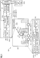
- FIGURE 1 depicts a scenario for detecting inside a vehicle VEH such as a bus the presence of a passenger PAS using a Smart Personal Communication Device SPCD, preferably a smartphone.
- vehicle VEH is preferably a public transport vehicle such as - besides the bus - train, city-/urban railway, underground/subway, tramway, taxi cab or airplane etc.
- the depicted scenario is based on a BIBO-system BSY formed by the vehicle VEH with a Vehicular Gateway VGW located therein and the passenger PAS with the Smart Personal Communication Device SPCD entering the vehicle VEH respectively the bus and thereby communicating with the Vehicular Gateway VGW via a communication link COL.
- the BIBO-system BSY is used for a BIBO-based electronic ticketing.
- the Vehicular Gateway VGW is connected with a Ticketing Service and Control Center TSCC.
- the electronic ticketing as a use case using presence detection of the passenger PAS inside the vehicle VEH is well known and thus not the subject matter of the present invention respectively the patent application.
- the use case of electronic ticketing is an appropriate example of a targeted deployment of the presence detection.
- the Smart Personal Communication Device SPCD and in particular well known components located therein are used, which are appropriate for this purpose. These components are a sensor SE, a processor PRC with a processor-assigned storage media STM and a transceiver unit TRU forming a Functional Unit FTU, whereby the processor PRC is connected each with the sensor SE and the transceiver unit TRU.
- the same Functional Unit FTU comprising the sensor SE, the processor PRC and the transceiver unit TRU is implemented in the Vehicular Gateway VGW.
- the Vehicular Gateway VGW includes a communication interface CIF connected also to the processor PRC which establishes the connection between the Vehicular Gateway VGW and the Ticketing Service and Control Center TSCC.
- each the sensor SE in the Smart Personal Communication Device SPCD generates a first sensor signal SS-1
- the sensor SE in the Vehicular Gateway VGW generates a second sensor signal SS-2, which could be regarded to some extent as a "reference signal” or simply "reference” to the first sensor signal SS-1.
- the first sensor signal SS-1 is depicted in the FIGURE 1 as a modified triangle (triangle with one curved triangle side)
- the second sensor signal SS-2 is depicted in the FIGURE 1 as a normal triangle (triangle with three straight triangle sides).
- the first sensor signal SS-1 is preferably a first acceleration signal ACS-1 or alternatively a first pressure signal PRS-1, a first humidity and temperature signal HTS-1, a first magnetic field signal MFS-1 or a first "Inertial Measurement Unit”-signal IMUS-1.
- the second sensor signal SS-2 is preferably a second acceleration signal ACS-2 or alternatively a second pressure signal PRS-2, a second humidity and temperature signal HTS-2, a second magnetic field signal MFS-2 or a second "Inertial Measurement Unit"-signal IMUS-2.
- the presence detection of the passenger PAS in the vehicle VEH is carried out. This presence detection can be done either in the Smart Personal Communication Device SPCD or alternatively in the Vehicular Gateway VHW.
- the second sensor signal SS-2 respectively the preferred or alternate modifications thereof must be transmitted from the Vehicular Gateway VGW via the communication link COL to the Smart Personal Communication Device SPCD.
- the way taken by this second sensor signal SS-2 starts at the sensor SE in the Vehicular Gateway VGW which generates and forwards it subsequently to the processor PRC which processes and forwards it then to the transceiver unit TRU, where the second sensor signal SS-2 is transmitted via the communication link COL to the transceiver unit TRU of the Smart Personal Communication Device SPCD, which forwards the second sensor signal SS-2 to the processor PRC of the Smart Personal Communication Device SPCD.
- the processor PRC carries out the cited presence detection of the passenger PAS in the vehicle VEH, because both sensor signals, the first sensor signal SS-1 and the second sensor signal SS-2, are preferably stored in the storage media STM and thus available in the processor PRC.
- the triangles of sensor signals are depicted in triangles with solid lines. How this presence detection is carried out will be described (further) below with regard to FIGURES 2 , 4 , 5 and 8 .
- the same signal way will be used in the case that the presence detection is done similarly in the Vehicular Gateway VGW, however, in the opposite direction which means that now the first sensor signal SS-1 respectively the preferred or alternate modifications thereof, is transmitted via the communication link COL from the Smart Personal Communication Device SPCD to the Vehicular Gateway VGW, where the presence detection is done in the processor PRC of the vehicular gateway VGW again according to FIGURES 2 , 4 , 5 and 8 .
- the triangles depicting the sensor signals are triangles with dashed lines.
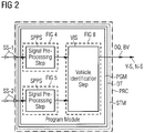
- FIGURE 2 shows a layout of a Digital Tool DT with a program module PGM for data processing being executable on a processor PRC, in particular the processor PRC of the Smart Personal Communication Device SPCD or the Vehicular Gateway VGW in the vehicle VEH for detecting the presence of the passenger PAS using the Smart Personal Communication Device SPCD, preferably the smart phone, according to the FIGURE 1 .
- the program module PGM is preferably downloadable from a server or cloud or is uploadable e.g. via a "Universal Serial Bus [USB]"-stick.
- the Digital Tool DT respectively the program module PGM is stored, uploadable or downloadable into a computer-readable storage media STM being inserted or insertable into or integrated in the Smart Personal Communication Device SPCD or the Vehicular Gateway VGW with the processor PRC.
- the computer-readable storage media STM is assigned to the processor PRC and forms with the processor PRC a common functional unit such that the processor PRC executes the program module PGM stored in the storage media STM.
- the program module PGM designed preferably as an algorithm uses as input quantities for the presence detection at least one first sensor signal SS-1 and at least one second sensor signal SS-2 generated by the sensors SE of the Smart Personal Communication Device SPCD and the Vehicular Gateway VHW according to the FIGURE 1 .
- the program module PGM respectively the algorithm is able to generate an output quantity OQ which indicates whether due to the two sensor signals SS-1, SS-2 being generated the presence of the passenger in the vehicle is detected or not.
- the program module PGM respectively the algorithm returns preferably a Boolean value BV indicating whether the passenger is inside the vehicle ("YES") or not ("NO").
- the program module PGM of the Digital Tool DT processes the first sensor signal SS-1 and the second sensor signal SS-2 independently in each a Signal Pre-Processing Step SPPS. After that both the pre-processed first sensor signal SS-1 and the pre-processed second sensor signal SS-2 are further processed in a Vehicle Identification Step VIS, before a "YES"-Statement Y-S or a "NO"-Statement N-S is made and the corresponding output quantity OQ respectively the Boolean value BV is provided or outputted.
- FIGURE 3a shows an exemplary record of preferred passenger-related first acceleration signals ACS-1 generated preferably by an accelerometer or an accelerometer and a gyroscope due to measuring acceleration forces on all three physical axes ⁇ "X, Y, Z"> being exerted on the Smart Personal Communication Device SPCD used by the passenger PAS according to the FIGURE 1 used as the at least one passenger-related first sensor signal SS-1.
- the passenger-related signal is superimposed by acceleration resulting from the passenger interacting with the smartphone that was used for signal recording.
- the first acceleration signals ACS-1 relating to the three physical axes ⁇ "X, Y, Z"> are marked with "X", "Y", "Z".
- FIGURE 3b shows an exemplary record of preferred vehicle-related second acceleration signals ACS-2 generated preferably by an accelerometer or an accelerometer and a gyroscope due to measuring acceleration forces on all three physical axes ⁇ "x, y, z"> being exerted on the vehicle VEH respectively the Vehicular Gateway VGW in the vehicle VEH according to the FIGURE 1 used as the at least one vehicle-related second sensor signal SS-2.
- the second acceleration signals ACS-2 relating to the three physical axes ⁇ "X, Y, Z"> are marked with "X", "Y", "Z".
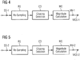
- FIGURE 4 shows a layout of the Signal Pre-Processing Step SPPS of the Digital Tool DT according to the FIGURE 2 for pre-processing the at least one passenger-related first sensor signal SS-1 of the Smart Personal Communication Device SPCD.
- Goal of the pre-processing is the conversion of the device-dependant input signals to signals with specified properties, e.g. specified sampling rate. Furthermore several checks are performed to identify invalid signals that violate minimum standards, e.g. minimum signal length.
- the Signal Pre-Processing Step SPPS of the algorithm consists of three sub-steps a first pre-processing sub-step performing a Re-Sampling RS, a second pre-processing sub-step performing a Clipping Detection CD and a third pre-processing sub-step performing a Magnitude Calculation MC as shown in the FIGURE 4 . From these sub-steps the first pre-processing sub-step performing the Re-Sampling RS and the third pre-processing sub-step performing the Magnitude Calculation MC are mandatory for the presence detection, whereas the second pre-processing sub-step performing the Clipping Detection CD is optional.
- the Re-Sampling RS is performed, because the recorded data included the passenger-related first sensor signals SS-1 respectively the preferred passenger-related first acceleration signals ACS-1 has/have a non-uniformly distributed sampling rate of approximately 100 Hz.
- the Re-Sampling of the signal at a constant sampling rate of 200 Hz is necessary, because some of the following sub-steps of the Signal Pre-Processing Step SPPS and the Vehicle Identification Step VIS rely on a discrete time signal with a constant sampling rate.
- the first pre-processing sub-step is followed by the optional second pre-processing sub-step performing the Clipping Detection CD.
- Acceleration sensors such as a preferred accelerometer measure the acceleration in m/s 2 in all three axes or an accelerometer and a gyroscope measuring the the acceleration in m/s 2 and the angular velocity in °/s in all three axes.
- Clipping occurs at approximately ⁇ 2 g (with 1 g ⁇ 9.81 m/s 2 ) for all smartphones used during the project. Clipping changes the time series in a way that cannot be reconstructed. In the frequency domain, clipping usually introduces harmonics that cannot be removed without loss of information, therefore clipping needs to be avoided.
- Clipping usually occurs in the axis pointing towards earth first, because it has an offset of 1 g that is more easily brought to clipping by adding a mere 1 g. This can happen easily by smashing the device onto a hard surface. Therefore clipping detection uses an "OR"-operation to concatenate the clipping indicators of all three axes.
- Clipping detection serves three functions:
- FIGURE 6a shows a record of the passenger-related first acceleration signals ACS-1 after a Clipping Detection with a heavy signal clipping according to the FIGURE 4 .
- the first acceleration signals ACS-1 after the Clipping Detection and the parts thereof relating each to the three physical axes ⁇ "X, Y, Z"> are marked with "X", "Y", "Z”.
- the passenger-related first acceleration signals ACS-1 would be marked as invalid by clipping detection, because the longest unclipped signal portion is shorter than 40 seconds.
- the second pre-processing sub-step is followed by the mandatory third pre-processing sub-step performing the Magnitude Calculation MC.
- the 3-component acceleration vectors from the measurements of both, the passenger-related first sensor signals SS-1 respectively the preferred passenger-related first acceleration signals ACS-1 and the vehicle-related second sensor signals SS-2 respectively the preferred vehicle-related second acceleration signals ACS-2 have to be reduced to single-component vectors.
- This demand results from the freedom of rotation around all axes that a smartphone usually has during normal user interaction.
- the reference measurement unit can be installed at pre-defined orientation (e.g. x axis pointing towards the direction of travel and z axis pointing towards earth), the user might rotate his or her smartphone freely around all axes.
- the typical and well-known coordinate system definition used for smartphones is depicted.
- * is the result of the Signal Pre-Processing Step SPPS in the program module PGM. According to the FIGURE 4 the calculation of
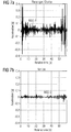
- FIGURE 7a shows based on the exemplary record shown in FIGURE 3a a record of a first Magnitude Calculation Signal MCS-1 including the first signal-specific magnitude values MV-1 after the Magnitude Calculation MC according to the FIGURE 4 .
- FIGURE 5 shows a layout of a Signal Pre-Processing Step SPPS of the Digital Tool DT according to the FIGURE 2 for pre-processing the at least one vehicle-related second sensor signal SS-2 of the vehicle VEH respectively the Vehicular Gateway VGW in the vehicle VEH.
- the goal of the pre-processing is the conversion of the device-dependant input signals to signals with specified properties, e.g. specified sampling rate.
- several checks are performed to identify invalid signals that violate minimum standards, e.g. minimum signal length.
- the Signal Pre-Processing Step SPPS of the algorithm comprises again the three sub-steps the first pre-processing sub-step performing the Re-Sampling RS, the second pre-processing sub-step performing the Clipping Detection CD and the third pre-processing sub-step performing the Magnitude Calculation MC as shown in the FIGURE 5 .
- the first pre-processing sub-step performing the Re-Sampling RS and the third pre-processing sub-step performing the Magnitude Calculation MC are mandatory for the presence detection, whereas the second pre-processing sub-step performing the Clipping Detection CD is optional.
- the Re-Sampling RS is performed, because the recorded data included the vehicle-related second sensor signals SS-2 respectively the preferred vehicle-related second acceleration signals ACS-2 has/have a non-uniformly distributed sampling rate of approximately 100 Hz.
- the Re-Sampling of the signal at a constant sampling rate of 200 Hz is necessary, because some of the following sub-steps of the Signal Pre-Processing Step SPPS and the Vehicle Identification Step VIS rely on a discrete time signal with a constant sampling rate.
- the first pre-processing sub-step is followed by the optional second pre-processing sub-step performing the Clipping Detection CD.
- Acceleration sensors such as a preferred accelerometer measure the acceleration in m/s 2 in all three axes or an accelerometer and a gyroscope measuring the acceleration in m/s 2 and the angular velocity in °/s in all three axes.
- Clipping occurs at approximately ⁇ 2 g (with 1 g ⁇ 9.81 m/s 2 ) for all smartphones used during the project. Clipping changes the time series in a way that cannot be reconstructed. In the frequency domain, clipping usually introduces harmonics that cannot be removed without loss of information, therefore clipping needs to be avoided.
- Clipping usually occurs in the axis pointing towards earth first, because it has an offset of 1 g that is more easily brought to clipping by adding a mere 1 g. This can happen easily by smashing the device onto a hard surface. Therefore clipping detection uses an "OR"-operation to concatenate the clipping indicators of all three axes.
- Clipping detection serves three functions:
- FIGURE 6b shows a record of the vehicle-related second acceleration signals ACS-2 after a Clipping Detection with a heavy signal clipping according to the FIGURE 5 .
- the second acceleration signals ACS-2 after the Clipping Detection and the parts thereof relating each to the three physical axes ⁇ "X, Y, Z"> are marked with "X", "Y", "Z”.
- the second pre-processing sub-step is followed by the mandatory third pre-processing sub-step performing the Magnitude Calculation MC.
- the 3-component acceleration vectors from the measurements of both, the passenger-related first sensor signals SS-1 respectively the preferred passenger-related first acceleration signals ACS-1 and the vehicle-related second sensor signals SS-2 respectively the preferred vehicle-related second acceleration signals ACS-2 have to be reduced to single-component vectors.
- This demand results from the freedom of rotation around all axes that a smartphone usually has during normal user interaction.
- the reference measurement unit can be installed at pre-defined orientation (e.g. x axis pointing towards the direction of travel and z axis pointing towards earth), the user might rotate his or her smartphone freely around all axes.
- the typical and well-known coordinate system definition used for smartphones is depicted.
- FIGURE 7b shows based on the exemplary record shown in FIGURE 3b a record of a second Magnitude Calculation Signal MCS-2 including the second signal-specific magnitude values MV-2 after the Magnitude Calculation MC according to the FIGURE 5 .
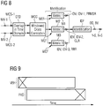
- FIGURE 8 shows a layout of the Vehicle Identification Step VIS of the Digital Tool DT according to the FIGURE 2 for the pre-processed first and second sensor signals SS-1, SS-2 according to the FIGURES 4 and 5 .
- the Vehicle Identification Step VIS of the algorithm compares the passenger-related first sensor signal SS-1 with the vehicle-related second sensor signal SS-2 using a "Cross-Correlation Function [CCF]". Further three metrics are applied to identify if the passenger PAS was travelling inside the vehicle VEH or not.
- CCF Cross-Correlation Function
- the Vehicle Identification Step VIS of the algorithm consists of four sub-steps a first identification sub-step performing an "Overlap in Time Domain" OTD, a second identification sub-step performing a "Windowed Cross Correlation" WCC, a third identification sub-step performing a Metrification MEF and a fourth identification sub-step performing a Identification IDF as shown in the FIGURE 8 . All these sub-steps are mandatory for the presence detection.
- the "Overlap in Time Domain" OTD is performed, where both signals, the first Magnitude Calculation Signal MCS-1 and the second Magnitude Calculation Signal MCS-2, are checked for sufficient overlap in the time domain.
- FIGURE 9 shows according to a principle diagram when the pre-processed passenger-related first sensor signal SS-1 and the vehicle-related second sensor signals SS-2 according to the FIGURES 4 and 5 in the form of the first Magnitude Calculation Signal MCS-1 and the second Magnitude Calculation Signal MCS-2 are overlapped in the time domain.
- the remaining part (the non-overlapped part) has to be long enough for identification (e.g. 40 seconds); otherwise the measurement is marked invalid and cannot be processed.
- the first identification sub-step is followed by the second identification sub-step performing the "Windowed Cross Correlation" WCC.
- the actual correlation is calculated by a "Windowed Cross Correlation"-function which is represented by a series of correlation functions applied on a "Sliding Window” over each entire valid Magnitude Calculation Signal MCS-1, MCS-2.
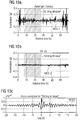
- FIGURE 10a shows the pre-processed passenger-related first sensor signal SS-1 according to the FIGURE 4 in the form of the first Magnitude Calculation Signal MCS-1 according to the FIGURE 7a with a "Sliding Window", which is depicted by the grey rectangle in the FIGURE.
- FIGURE 10b shows the pre-processed vehicle-related second sensor signal SS-2 according to the FIGURE 5 in the form of the second Magnitude Calculation Signal MCS-2 according to the FIGURE 7b with a "Sliding Window", which is depicted by the grey rectangle in the FIGURE.
- FIGURE 10c shows based on the exemplary record shown in the FIGURES 10a and 10b the illustrative application of the "Windowed Cross-Correlation” (WCC).
- WCC Windowed Cross-Correlation
- the first one is the window width, which is set to 20 seconds.
- the second parameter is the step size for the window movement, which is set to 1 second.
- the peak value and the peak position (which comply with a lag) of the "Cross-Correlation Functions [CCF]" are recorded for all “Cross-Correlation Windows” independently.
- the "Cross-Correlation Functions [CCF]” themselves are furthermore summarized over all “Cross-Correlation Windows” resulting in an averaged “Cross-Correlation Function [CCF]". Those values are used by the identification metrics for vehicle identification, but only, if the peak lag is within +/- 2 seconds of lag (0). Vehicle-related and passenger-related measurements have to be synchronized better than 2 seconds in time domain for a valid measurement pair.
- the second identification sub-step is followed by the third identification sub-step performing the Metrification MEF.
- Goal of the Metrification MEF is to induce at least one metrification-based identification value IDV.
- the Metrification MEF is constituted by at least one of three different metrics, a first metric M1 defining a "Peak-to-Root Mean Square [RMS]"-Ratio PRMSR of the "Windowed Cross-Correlation [WCC]"-function ( cf.
- FIGURE 10c whereby the "Root Mean Square [RMS]" of the WCC-function is called “Cross-Correlation Energy [CCE]", a second metric M2 defining a "Peak Lag Value with the highest percentage of all Peak Lag Values over all Cross-Correlation Windows” called as “Correlation Lag Ratio” CLR and a third metric M3 defining a "ratio of a largest part of "Cross-Correlation Energy [CCE]” to a remainder of the “Cross-Correlation Energy [CCE]” over all “Cross-Correlation Windows”” called as "RMS-to-RMS ratio" RRR.
- RRR Root Mean Square
- the first metric M1 generates a first metrification-based identification value IDV-1, which corresponds to the "Peak-to-Root Mean Square [RMS]"-Ratio PRMSR
- the second metric M2 generates a second metrification-based identification value IDV-2, which corresponds to the "Correlation Lag Ratio” CLR
- the third metric M3 generates a third metrification-based identification value IDV-3", which corresponds to the "RMS-to-RMS ratio" RRR.
- All metrification-based identification values IDV, IDV-1, IDV-2, IDV-3 are transferred as input quantities for the fourth identification sub-step performing the Identification IDF.
- the third identification sub-step Vehicle Identification Step VIS performing the Metrification MEF is mandatory for the presence detection this does not mean inevitable that all three metrics are mandatory too. It is sufficient that at least one must be processed, whereas the two other can be processed optionally.
- the at least one metrification-based identification value IDV, IDV-1, IDV-2, IDV-3 is compared each with an overall threshold value THV, which is preferably at least one of arbitrary and determined experimentally or automatically, such that, if one of the at least one metrification-based identification value IDV, IDV-1, IDV-2, IDV-3 is below or below and equal to the threshold value THV, the "NO"-statement N-S regarding the presence of the passenger PAS in the vehicle VEH is made otherwise the "YES"-statement Y-S regarding the presence of the passenger PAS in the vehicle VEH is made, whereby in particular the output quantity OQ is provided correspondingly, which is preferably the Boolean value BV.
- THV which is preferably at least one of arbitrary and determined experimentally or automatically
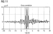
- FIGURE 11 shows based on the exemplary record shown in the FIGURE 10c the illustrative application of the Metrification MEF according to the Vehicle Identification Step VIS shown in the FIGURE 8 using the first metric M1 defining of a "Windowed cross-correlation [WCC]"-function shown in the FIGURE 10c an exemplary, illustrative "Peak-to-Root Mean Square [RMS]"-Ratio PRMSR calculation with the "Root Mean Square [RMS]" of the WCC-function called as "Cross-Correlation Energy [CCE]".
- WCC Vehicle Identification Step VIS
- the "lag" of the correlation function peak is +50 ms and its magnitude is 8.5e-5.
- a region centered on the "peak” is cut out with 4 seconds width. This region is used for the "Peak-to-Root Mean Square [RMS]"-Ratio PRMSR calculation.
- the "Peak-to-Root Mean Square [RMS]"-Ratio PRMSR is above the threshold value while the measurements have not been recorded in the same vehicle.
- the reason might be nearly identical acceleration profiles for a short period of time, but not for the entire signal duration. This might lead to an averaged "Cross-Correlation Function [CCF]” with a high “Peak-to-Root Mean Square [RMS] "-Ratio, although the maximum peak position differs from window to window; the "Cross-Correlation Functions [CCF]” do not cohere from signal start to signal end.
- the second metric M2 is used.
- the percentage or the “Correlation Lag Ratio” CLR is calculated.
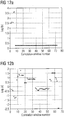
- FIGURE 12a shows based on the application of the Metrification MEF according to the Vehicle Identification Step VIS shown in the FIGURE 8 using the second metric M2 defining the "Peak Lag Value with the highest percentage of all Peak Lag Values over all cross-correlation windows” M2 called as the “Correlation Lag Ratio" CLR the "lags" of individual "Cross-Correlation Windows” for signal pairs with a high (e.g. 90.3%) "Correlation Lag Ratio" CLR.
- FIGURE 12b shows based on the application of the Metrification MEF according to the Vehicle Identification Step VIS shown in the FIGURE 8 using the second metric M2 defining the "Peak Lag Value with the highest percentage of all Peak Lag Values over all cross-correlation windows” called as the “Correlation Lag Ratio" CLR the "lags" of individual "Cross-Correlation Windows” for signal pairs with a low (e.g. 13.9%) "Correlation Lag Ratio" CLR.
- the introduced first and second metrics M1, M2 above are not strong enough in some cases used with low accelerated vehicles VEH such as suburban trains (called S-Bru in German). This is expressed in the fact that the form of the resulted correlation differs from those other vehicles.
- the correlation peak is much smaller.
- this peak is also much wider.
- the largest part of the correlation energy (“Root Mean Square [RMS]"
- RMS Root Mean Square
- the third metric M3 is used.
- this metric defining a "ratio of a largest part of "Cross-Correlation Energy [CCE]” to a remainder of the “Cross-Correlation Energy [CCE]”over all “Cross-Correlation Windows”" called as the "RMS-to-RMS Ratio” RRR the ratio or the “RMS-to-RMS Ratio” RRR is calculated.
- This process is similar to the first metric and the threshold for it is about 3.
- This third metric works reliably with respect to acceleration data measured in suburban trains.
- each vehicle-related measurement should be assigned to a vehicle classification (e.g. bus, tram, suburban train, etc.). Therefore, the corresponding third metric can be applied depending on this classification.
- the first and the second metrics M1, M2 of the three metrics M1, M2, M3 are used in the Vehicle Identification Step VIS.
- the statement being made is positive (or true), if the first and the second metrics M1, M2 are above their respective threshold values.
- the vehicle is a suburban train (S-Bru) then according to a further preferred embodiment only the third metric M3 of the three metrics M1, M2, M3 is used in the Vehicle Identification Step VIS. With respect to this metric M3 the statement being made is positive (or true), if the third metric is above its threshold value.
- the metrics M1, M2 respectively the metric M3 of the preferred embodiments, being used in the Vehicle Identification Step VIS is below its threshold value, the statement being made is negative (or false).
Landscapes
- Engineering & Computer Science (AREA)
- Computer Networks & Wireless Communication (AREA)
- Signal Processing (AREA)
- Aviation & Aerospace Engineering (AREA)
- Physics & Mathematics (AREA)
- Finance (AREA)
- Business, Economics & Management (AREA)
- General Physics & Mathematics (AREA)
- Health & Medical Sciences (AREA)
- Computing Systems (AREA)
- General Health & Medical Sciences (AREA)
- Medical Informatics (AREA)
- Traffic Control Systems (AREA)
- Electric Propulsion And Braking For Vehicles (AREA)
Description
- The invention refers to a Method for presence detection inside a vehicle of a passenger using a Smart Personal Communication Device according to the preamble of
claim 1, a Digital Tool for presence detection inside a vehicle of a passenger using a Smart Personal Communication Device according to the preamble of claim 9, a Smart Personal Communication Device for presence detection inside a vehicle of a passenger using a Smart Personal Communication Device according to the preamble of claim 19, a Vehicular Gateway for presence detection inside a vehicle of a passenger using a Smart Personal Communication Device according to the preamble of claim 27 and a BIBO-System according to the preamble of claim 35. - To detect accurately the presence inside a vehicle of a passenger in general a variety of sensors measuring the presence can be used as there are a light sensor, a proximity sensor, an accelerometer, a gyroscope, a pressure sensor, a relative humidity sensor and temperature sensor, a magnetic field sensor or an "Inertial Measurement Unit [IMU]".
- The advantage of the given sensor types is that they are mostly implemented or realized in nowadays modern smartphones, e.g. those with Android operating system. The modern smartphones include multiple sensors to enable programmers to develop more sophisticated apps and games for smartphones, where users do not only tab on the screen for interacting with their smartphones, but e.g. rotate and shake it, or use their smartphone as a compass.
- Of course, smartphones don't necessarily include sensors of every single type. In general, many devices already have an accelerometer and a compass built-in, but, today, few have barometers. Moreover, a device can have more than one sensor of the same type. Sensor availability doesn't only vary from device to device; it can also vary between versions of the Android on the same device.
- Some of the sensors are hardware-based, some software-based. Hardware-based sensors are physical components built into the devices. They gather their data by measuring specific environmental properties. Software-based or virtual sensors deliver information after applying signal processing on data from one or multiple hardware-based sensors.
- Besides the sensors listed above, more components inside smartphones exist which could be used for environmental pattern recording. The microphone as an example could be used to listen to specific sound patterns outside of the human hearing range generated by a gateway in a specific vehicle such as a bus in order to clearly relate the smartphone to the vehicle respectively the bus. However due to privacy concerns, using the microphone or the camera were excluded as part of the presence detection in a vehicle environment.
- Nevertheless a smartphone will be an appropriate candidate for detecting accurately the presence of a passenger inside a vehicle.
- The presence detection in a vehicle environment, especially when the vehicle is a public transport vehicle such as bus, train, city-/urban railway, underground/subway, tramway, taxi cab or airplane etc., opens up diverse application perspectives with regard to electronic ticketing.
- Electronic ticketing has been with us for quite a while. Tickets for air travel are already mainly electronic, and a similar case can be seen with long distance train travel. Such tickets are usually bought in advance, for example through electronic means.
- Even more convenient travel experiences for passengers can be achieved by removing the need for booking tickets in advance. In order to achieve this, two concepts exist: "Check In/Check Out [CICO]" and "Be In/Be Out [BIBO]".
- The CICO-concept implies manually checking into a vehicle or station, travelling, and then manually checking out. This checking in and out may be done by moving an identification card close to a reader in the vehicle/station, or other methods like clicking on a smartphone screen. An advantage of the CICO-systems over the regular electronic booking is that no preparation has to be taken in advance, allowing for spontaneous travel. Another advantage is that the traveler only has to pay for the travel segments that were actually used.
- The BIBO-concept goes beyond and even removes the necessity for checking in and out of the vehicle/station manually, achieving a detection and identification of the passenger through automatic means. The BIBO-approach allows travelers to hop on and off vehicles, meanwhile automatically booking the proper ticket.
- The most difficult problem to be solved by a BIBO-system is to accurately detect the presence of a passenger inside a vehicle.
- The way most BIBO-systems are working is to include a wireless transceiver inside a credit card sized dedicated BIBO-ticket. This ticket will either actively send beacons, which may be read by a bus (or any other public transport vehicle) in the direct vicinity. Another option is for the BIBO-ticket to receive beacons sent by the vehicle, as to know inside which vehicle it is located. Usually, a communications protocol will take care of securely exchanging ID information, to authenticate and eventually bill the customer.
- The coupling between vehicle and passenger is thus made just by observing which vehicle can be seen by the passenger's BIBO-device (or which BIBO-device can be seen by the vehicle) during the travel from one station to the next. The wireless range will thus be the defining factor for this coupling, and a constant polling will make sure that the passenger is still inside the vehicle.
- Such systems may be effective for long range train travel as well as air travel, but important problems arise with shorter distances. As an example, if a person has a BIBO-ticket and drives with his or her car next to a BIBO-enabled bus during a traffic jam, it is very probable that the BIBO-ticket will be in wireless range of the bus, and thus the person would be detected as being inside the bus. Such a scenario leads to "false positives" and hence, customer complaints. A similar example leading to "false positives" would be a bicycle driver behind a bus during rush hour.
- Some solutions have been proposed in the state-of-the-art to reduce these "false positives", which typically lead to additional infrastructure making the system more costly and complicated.
- Another important challenge is low power usage. If the BIBO-ticket contains active component and a battery, power management techniques must ensure than said battery can live for a long time.
- From the prior published German Patent Application (
DE 10 2012 009 610 A1 - The method/device enables acquiring and billing of the service fees with less installation and circuitry effort while ensuring enhanced riding of the passenger and recognition of the passenger in the vehicle.
- As smartphones are wide spread and many people use them in their daily life, the idea is to turn smartphones into BIBO-devices. Smartphones come with many built in sensors, e.g. accelerometer, pressure sensor and a compass, which can be used to create a specific profile. This profile will be unique to the vehicle in which it was recorded and will be compared to the vehicle's profile.
- A Smartphone-based BIBO-system includes not only the smartphone but consists of all the following components:
- Vehicle: e.g. bus or tram,
- BIBO Gateway (BGW): BIBO communication gateway (WLAN, Bluetooth and/or mobile communication) including a sensor unit,
- Smartphone: Customer's device including sensors and wireless communication (WLAN, Bluetooth and/or mobile communication),
- App: Software application running on the customer's smartphone.
- A smartphone being carried by a passenger will be subjected to the same environment than that of the vehicle it is being carried on. Using acceleration as an example of a possible sensor measurement, the smartphone's and the bus's sensor will be exposed to the same forces. Differences in the acceleration experienced by the smartphone and the vehicle will typically come from usage of the phone (e.g. web surfing, making a call) or because of the means of propagation of the acceleration to the smartphone (e.g. a passenger holding a rail of the bus will have a delay between the propagation of the acceleration to the smartphone).
- Comparing the pattern obtained between the smartphone and the vehicle, one can identify if they are in the same vehicle. This comparison will be typically done on a BIBO-Gateway due to security reasons and power consumption, but for privacy reasons it may as well be done on the smartphone. Time stamp synchronization will be performed before recording and transmitting data in order to enhance the presence detection.
- The light sensor and the proximity sensor offer no reasonable possibility of determining presence inside a specific bus or public transport vehicle, since the smartphone can be in a bag the whole time.
- Another important challenge is as already mentioned low power usage. So the goal is to use as few sensors as possible. Low power usage of each sensor will also be preferred.
- The pressure sensor measures the ambient air pressure in hPa or mbar. Relative changes in height can be determined quite well (based on our measurements changes in height of 1 meter can be identified), whereas absolute values differ strongly from smartphone device to device (two smartphones next to each other can present absolute height differences of 10 meters). Due to the low sampling rate (∼4 measurements per second) and the relatively high noise in the raw measurements, important delays can present themselves when measuring. For this reason, those relative changes (for example when driving downhill) will not significantly differ between two closely spaced vehicles driving along the same path.
- Relative humidity is the ratio of the partial pressure of water vapor in an air-water mixture to the saturated vapor pressure of water at a prescribed temperature. Relative humidity, expressed as a percent, measures the current absolute humidity relative to the maximum for that temperature. The relative ambient humidity is measured in percent (%) and the temperature is measured in degrees Celsius (°C). Absolute humidity is the water content of air.
- The noise and value offset present in the smartphones' sensors for relative humidity is very low, which could make it feasible to use this sensors to find out if two sensors are located in the same vehicle. As the water content of air will be directly affected by the specific amount of people inside a vehicle, it may be used for obtaining a fingerprint of the vehicle.
- One important factor to take into account is that the relative humidity can change very fast as the temperature of the sensor (in this case the phone) changes. As the temperature of the sensor is known by the temperature sensor in the phone, one can compensate this to obtain the absolute humidity.
- This sensor measures the ambient geomagnetic field for all three physical axes <"x, y, z"> in µT. Changes in direction can be determined in a very rough fashion. As long as the smartphone is not exposed to magnets or metal objects, the magnetic field sensor could be used to determine how the orientation of the smartphone is in relation to the bus's orientation.
- The acceleration force is measured in m/s2 on all three physical axes <"x, y, z"> including the force of gravity. The gyroscope measures a device's rate of rotation in rad/s around each of the three physical axes <"x, y, z">. The accelerometer also is sensitive enough to allow a distinction between two closely spaced vehicles following the same path.
- Since bus movement, user movement and smartphone usage have individual impact to the axis rotation of a smartphone, the gyroscope can barely support to answer the question in which position the smartphone resides and much less the gyroscope offer a distinct pattern to determine the presence of a smartphone inside a vehicle. The gyroscope as a stand-alone sensor is not sufficient.
- An inertial measurement unit (IMU) is a device that embeds usually an accelerometers and gyroscopes, sometimes also magnetometers. Highly expensive IMUs are usually used as an inertial navigation system used in airplanes, spacecraft or even vessels. Data collected from the IMU's sensors allows a computer to track a craft's position, using a method known as dead reckoning.
- The usage within a smartphone BIBO system is not to determine the position, but the movement pattern of a public transport vehicle, e.g. a bus. Inside each public transport vehicle, at least one IMU will be installed, recording the movement of the bus. This measurement will serve as a reference measurement to which all measurements recorded from smartphones potentially inside the bus need to be compared to.
- It is an object of the invention to detect presences inside vehicles of passengers using Smart Personal Communication Devices, in particular smartphones, and propose a Method, a Digital Tool, the Device, a Gateway and a BIBO-System used therefore, which each enables easily with a minimum of hardware complexity an automated accurate detection of the coupling between the passenger and the vehicle.
- This object is solved based on a Method for presence detection defined in the preamble of
claim 1 by the features in the characterizing part ofclaim 1. - This object is further solved based on a Digital Tool for presence detection defined in the preamble of claim 9 by the features in the characterizing part of claim 9.
- Furthermore the object is solved based on a Smart Personal Communication Device for presence detection defined in the preamble of claim 19 by the features in the characterizing part of claim 19.
- Moreover the object is solved based on a Vehicular Gateway for presence detection defined in the preamble of claim 27 by the features in the characterizing part of claim 27.
- All after the object is also solved based on a BIBO-System for presence detection defined in the preamble of claim 35 by the features in the characterizing part of claim 35.
- The idea underlying the invention is to detect the presence inside a vehicle of a passenger using a Smart Personal Communication Device, in particular a smartphone, by
- (a) executing in a Signal Pre-Processing Step of independently pre-processing at least one passenger-related first sensor signal of the Smart Personal Communication Device and at least one vehicle-related second sensor signal of the vehicle for each of the first and second signals at least a Re-Sampling and a Magnitude Calculation to induce signal-specific magnitude values, which could be complemented each by executing a Clipping Detection being executed preferably between the Re-Sampling and the Magnitude Calculation,
- (b) applying in a Vehicle Identification Step for comparing the signal-specific magnitude values a "Cross-Correlation Function [CCF]" such that the signal-specific magnitude values are executed in the order of "Overlapping in Time Domain", "Windowed Cross-Correlation" and Metrification, in particular by at least one of three different metrics, to induce due to the Metrification at least one metric-based identification value and
- (c) comparing in the Vehicle Identification Step the at least one metrification-based identification value each with an overall threshold value such that, if one of the at least one metrification-based identification value is below or below and equal to the threshold value, a "NO"-statement regarding the presence of the passenger in the vehicle is made otherwise a "YES"-statement regarding the presence of the passenger in the vehicle is made, whereby in particular an output quantity is provided correspondingly, which is preferably a Boolean value.
- This idea is realized in a Method for presence detection (cf. claim 1), a Digital Tool for presence detection (cf. claim 9), a Smart Personal Communication Device for presence detection (cf. claim 19), a Vehicular Gateway for presence detection (cf. claim 27) and a BIBO-System for presence detection (cf. claim 35).
- Of a sui generis design the subject matter of the invention is preferably on one side either a Method or a Digital Tool and on the other either a Device, a Gateway or a System.
- The Digital Tool according to the claim 9 includes a program module running on a processor, whereby the program module is preferably downloadable from a server or cloud (cf. claim 17) or is uploadable via a "Universal Serial Bus [USB]"-stick (cf. claim 18) or in addition is stored, uploadable or downloadable into a storage media being inserted or insertable into the Device or the Gateway including a processor (cf. claim 19 respectively claim 27). Regarding the cited options (alternatives) the Digital Tool is preferably an "App" (Application Software) running on processors of different radio devices, which could be a desktop PC or an "All-In-One" PC incorporating each a radio interface, a smartphone, a notebook, a tablet etc. In other words the Digital Tool is preferably a purpose-designed computer program product. The Digital Tool can be sold or distributed separately or in common with the Device, the Gateway or the System for presence detection. Such a Device, Gateway or System could be for example a telecommunication appliance, a vehicular controlling system, etc.
- Further expedient improvements of the invention associated with corresponding advantages are stated in the other dependent claims.
- Moreover other advantageous developments of the invention arise out of the following description of a preferred embodiment of the invention according to the
FIGURES 1 to 12b . They show: -
FIGURE 1 a scenario for detecting inside a vehicle, preferably a bus, the presence of a passenger using a Smart Personal Communication Device, preferably a smartphone, -
FIGURE 2 a layout of a Digital Tool with a program module for data processing being executable on a processor, in particular a processor of the Smart Personal Communication Device or a Vehicular Gateway in the vehicle for detecting the presence of the passenger using the Smart Personal Communication Device, preferably the smartphone, according to theFIGURE 1 , -
FIGURE 3a an exemplary record of first acceleration signals generated by an accelerometer or an accelerometer and a gyroscope due to measuring acceleration forces on all three physical axes <"x, y, z"> being exerted on the Smart Personal Communication Device used by the passenger according to theFIGURE 1 used as at least one passenger-related first sensor signal, -
FIGURE 3b an exemplary record of second acceleration signals generated by an accelerometer or an accelerometer and a gyroscope due to measuring acceleration forces on all three physical axes <"x, y, z"> being exerted on the vehicle respectively the Vehicular Gateway in the vehicle according to theFIGURE 1 used as at least one vehicle-related second sensor signal, -
FIGURE 4 a layout of a Signal Pre-Processing Step of the Digital Tool according to theFIGURE 2 for pre-processing the passenger-related first sensor signal of the Smart Personal Communication Device, -
FIGURE 5 a layout of a Signal Pre-Processing Step of the Digital Tool according to theFIGURE 2 for pre-processing the vehicle-related second sensor signal of the vehicle respectively the Vehicular gateway in the vehicle, -
FIGURE 6a a record of the pre-processed passenger-related acceleration signals after a Clipping Detection with a heavy signal clipping according to theFIGURE 4 , -
FIGURE 6b a record of the pre-processed vehicle-related second acceleration signals after a Clipping Detection according to theFIGURE 5 , -
FIGURE 7a based on the exemplary record shown inFIGURE 3a a record of a first Magnitude Calculation Signal after a Magnitude Calculation according to theFIGURE 4 , -
FIGURE 7b based on the exemplary record shown inFIGURE 3b a record of a second Magnitude Calculation Signal after a Magnitude Calculation according to theFIGURE 5 , -
FIGURE 8 a layout of a Vehicle Identification Step of the Digital Tool according to theFIGURE 2 for the pre-processed first and second sensor signals according to theFIGURES 4 and 5 , -
FIGURE 9 a principle diagram showing when the pre-processed first and second sensor signals according to theFIGURES 4 and 5 are overlapped in the time domain, -
FIGURE 10a based on the pre-processed passenger-related first sensor signal according to theFIGURE 4 a first Magnitude Calculation Signal according to theFIGURE 7a with a "Sliding Window", -
FIGURE 10b based on the pre-processed vehicle-related second sensor signal according to theFIGURE 5 a second Magnitude Calculation Signal according to theFIGURE 7b with a "Sliding Window", -
FIGURE 10c based on the exemplary record shown in theFIGURES 10a and 10b the illustrative application of the "Windowed Cross-Correlation [WCC]", -
FIGURE 11 based on the exemplary record shown in theFIGURE 10c the illustrative application of a Metrification according to the Vehicle Identification Step shown in theFIGURE 8 using a first metric defining of a "Windowed cross-correlation [WCC]"-function shown in theFIGURE 10c an exemplary, illustrative "Peak-to-Root Mean Square [RMS]"-Ratio calculation with the "Root Mean Square [RMS]" of the WCC-function called as "Cross-Correlation Energy [CCE]", -
FIGURE 12a based on the application of a Metrification according to the Vehicle Identification Step shown in theFIGURE 8 using a second metric defining a "Peak Lag Value with the highest percentage of all Peak Lag Values over all cross-correlation windows" called as "Correlation Lag Ratio" (CLR) the lags of individual correlation windows for signal pairs with a high (e.g. 90.3%) "Correlation Lag Ratio", -
FIGURE 12b based on the application of a Metrification according to the Vehicle Identification Step shown in theFIGURE 8 using a second metric defining a "Peak Lag Value with the highest percentage of all Peak Lag Values over all cross-correlation windows" called as "Correlation Lag Ratio" (CLR) the lags of individual correlation windows for signal pairs with a low (e.g. 13.9%) "Correlation Lag Ratio". -
FIGURE 1 depicts a scenario for detecting inside a vehicle VEH such as a bus the presence of a passenger PAS using a Smart Personal Communication Device SPCD, preferably a smartphone. However, the vehicle VEH is preferably a public transport vehicle such as - besides the bus - train, city-/urban railway, underground/subway, tramway, taxi cab or airplane etc. - The depicted scenario is based on a BIBO-system BSY formed by the vehicle VEH with a Vehicular Gateway VGW located therein and the passenger PAS with the Smart Personal Communication Device SPCD entering the vehicle VEH respectively the bus and thereby communicating with the Vehicular Gateway VGW via a communication link COL. In this context the BIBO-system BSY is used for a BIBO-based electronic ticketing. For this purpose the Vehicular Gateway VGW is connected with a Ticketing Service and Control Center TSCC. The electronic ticketing as a use case using presence detection of the passenger PAS inside the vehicle VEH is well known and thus not the subject matter of the present invention respectively the patent application.
- Nevertheless, the use case of electronic ticketing is an appropriate example of a targeted deployment of the presence detection. To carry out the cited presence detection the Smart Personal Communication Device SPCD and in particular well known components located therein are used, which are appropriate for this purpose. These components are a sensor SE, a processor PRC with a processor-assigned storage media STM and a transceiver unit TRU forming a Functional Unit FTU, whereby the processor PRC is connected each with the sensor SE and the transceiver unit TRU. The same Functional Unit FTU comprising the sensor SE, the processor PRC and the transceiver unit TRU is implemented in the Vehicular Gateway VGW. In addition for the electronic ticketing the Vehicular Gateway VGW includes a communication interface CIF connected also to the processor PRC which establishes the connection between the Vehicular Gateway VGW and the Ticketing Service and Control Center TSCC.
- Due to the usage of the sensor SE in both the Smart Personal Communication Device SPCD and the Vehicular Gateway VGW and its initial operation each the sensor SE in the Smart Personal Communication Device SPCD generates a first sensor signal SS-1, while the sensor SE in the Vehicular Gateway VGW generates a second sensor signal SS-2, which could be regarded to some extent as a "reference signal" or simply "reference" to the first sensor signal SS-1. The first sensor signal SS-1 is depicted in the
FIGURE 1 as a modified triangle (triangle with one curved triangle side), whereas the second sensor signal SS-2 is depicted in theFIGURE 1 as a normal triangle (triangle with three straight triangle sides). - Depending on whether the sensor SE in the Smart Personal Communication Device SPCD is preferably designed as an accelerometer or an accelerometer and a gyroscope or alternatively designed as a pressure sensor, a relative humidity sensor and temperature sensor, a magnetic field sensor or an "Inertial Measurement Unit"-sensor the first sensor signal SS-1 is preferably a first acceleration signal ACS-1 or alternatively a first pressure signal PRS-1, a first humidity and temperature signal HTS-1, a first magnetic field signal MFS-1 or a first "Inertial Measurement Unit"-signal IMUS-1.
- Correspondingly, depending on whether the sensor SE in the Vehicular Gateway VGW is preferably designed as an accelerometer or an accelerometer and a gyroscope or alternatively designed as a pressure sensor, a relative humidity sensor and temperature sensor, a magnetic field sensor or an "Inertial Measurement Unit"-sensor the second sensor signal SS-2 is preferably a second acceleration signal ACS-2 or alternatively a second pressure signal PRS-2, a second humidity and temperature signal HTS-2, a second magnetic field signal MFS-2 or a second "Inertial Measurement Unit"-signal IMUS-2.
- Based on the first sensor signal SS-1 and the second sensor signal SS-2 respectively each the preferred manifestation ACS-1, ACS-2 or the alternate manifestation PRS-1, PRS-2, ATS-1, ATS-2, MFS-1, MFS-2, IMUS-1, IMUS-2 the presence detection of the passenger PAS in the vehicle VEH is carried out. This presence detection can be done either in the Smart Personal Communication Device SPCD or alternatively in the Vehicular Gateway VHW.
- When the presence detection is done in the Smart Personal Communication Device SPCD the second sensor signal SS-2 respectively the preferred or alternate modifications thereof must be transmitted from the Vehicular Gateway VGW via the communication link COL to the Smart Personal Communication Device SPCD. The way taken by this second sensor signal SS-2 starts at the sensor SE in the Vehicular Gateway VGW which generates and forwards it subsequently to the processor PRC which processes and forwards it then to the transceiver unit TRU, where the second sensor signal SS-2 is transmitted via the communication link COL to the transceiver unit TRU of the Smart Personal Communication Device SPCD, which forwards the second sensor signal SS-2 to the processor PRC of the Smart Personal Communication Device SPCD. Being reached at the processor PRC of the Smart Personal Communication Device SPCD the processor PRC carries out the cited presence detection of the passenger PAS in the vehicle VEH, because both sensor signals, the first sensor signal SS-1 and the second sensor signal SS-2, are preferably stored in the storage media STM and thus available in the processor PRC. According to this option of presence detection in the Smart Personal Communication Device SPCD the triangles of sensor signals are depicted in triangles with solid lines. How this presence detection is carried out will be described (further) below with regard to
FIGURES 2 ,4 ,5 and8 . - The same signal way will be used in the case that the presence detection is done similarly in the Vehicular Gateway VGW, however, in the opposite direction which means that now the first sensor signal SS-1 respectively the preferred or alternate modifications thereof, is transmitted via the communication link COL from the Smart Personal Communication Device SPCD to the Vehicular Gateway VGW, where the presence detection is done in the processor PRC of the vehicular gateway VGW again according to
FIGURES 2 ,4 ,5 and8 . With regard to this option of presence detection in Vehicular Gateway VGW the triangles depicting the sensor signals are triangles with dashed lines. -
FIGURE 2 shows a layout of a Digital Tool DT with a program module PGM for data processing being executable on a processor PRC, in particular the processor PRC of the Smart Personal Communication Device SPCD or the Vehicular Gateway VGW in the vehicle VEH for detecting the presence of the passenger PAS using the Smart Personal Communication Device SPCD, preferably the smart phone, according to theFIGURE 1 . Thereby the program module PGM is preferably downloadable from a server or cloud or is uploadable e.g. via a "Universal Serial Bus [USB]"-stick. - Furthermore it is possible that the Digital Tool DT respectively the program module PGM is stored, uploadable or downloadable into a computer-readable storage media STM being inserted or insertable into or integrated in the Smart Personal Communication Device SPCD or the Vehicular Gateway VGW with the processor PRC. The computer-readable storage media STM is assigned to the processor PRC and forms with the processor PRC a common functional unit such that the processor PRC executes the program module PGM stored in the storage media STM.
- The program module PGM designed preferably as an algorithm uses as input quantities for the presence detection at least one first sensor signal SS-1 and at least one second sensor signal SS-2 generated by the sensors SE of the Smart Personal Communication Device SPCD and the Vehicular Gateway VHW according to the
FIGURE 1 . By inputting these two sensor signals SS-1, SS-2 the program module PGM respectively the algorithm is able to generate an output quantity OQ which indicates whether due to the two sensor signals SS-1, SS-2 being generated the presence of the passenger in the vehicle is detected or not. In other words the program module PGM respectively the algorithm returns preferably a Boolean value BV indicating whether the passenger is inside the vehicle ("YES") or not ("NO"). - For doing this kind of presence detection the program module PGM of the Digital Tool DT processes the first sensor signal SS-1 and the second sensor signal SS-2 independently in each a Signal Pre-Processing Step SPPS. After that both the pre-processed first sensor signal SS-1 and the pre-processed second sensor signal SS-2 are further processed in a Vehicle Identification Step VIS, before a "YES"-Statement Y-S or a "NO"-Statement N-S is made and the corresponding output quantity OQ respectively the Boolean value BV is provided or outputted. What happens in each of the Signal Pre-Processing Step SPPS for the first sensor signal SS-1 respectively the second sensor signal SS-2 is shown and described in more detail in respectively with respect to
FIGURE 4 or in respectively with regard toFIGURE 5 . InFIGURE 8 it is shown and respectively described in more detail the process carried out in the Vehicle Identification step VIS. -
FIGURE 3a shows an exemplary record of preferred passenger-related first acceleration signals ACS-1 generated preferably by an accelerometer or an accelerometer and a gyroscope due to measuring acceleration forces on all three physical axes <"X, Y, Z"> being exerted on the Smart Personal Communication Device SPCD used by the passenger PAS according to theFIGURE 1 used as the at least one passenger-related first sensor signal SS-1. The passenger-related signal is superimposed by acceleration resulting from the passenger interacting with the smartphone that was used for signal recording. The first acceleration signals ACS-1 relating to the three physical axes <"X, Y, Z"> are marked with "X", "Y", "Z". -
FIGURE 3b shows an exemplary record of preferred vehicle-related second acceleration signals ACS-2 generated preferably by an accelerometer or an accelerometer and a gyroscope due to measuring acceleration forces on all three physical axes <"x, y, z"> being exerted on the vehicle VEH respectively the Vehicular Gateway VGW in the vehicle VEH according to theFIGURE 1 used as the at least one vehicle-related second sensor signal SS-2. The second acceleration signals ACS-2 relating to the three physical axes <"X, Y, Z"> are marked with "X", "Y", "Z". -
FIGURE 4 shows a layout of the Signal Pre-Processing Step SPPS of the Digital Tool DT according to theFIGURE 2 for pre-processing the at least one passenger-related first sensor signal SS-1 of the Smart Personal Communication Device SPCD. Goal of the pre-processing is the conversion of the device-dependant input signals to signals with specified properties, e.g. specified sampling rate. Furthermore several checks are performed to identify invalid signals that violate minimum standards, e.g. minimum signal length. - The Signal Pre-Processing Step SPPS of the algorithm consists of three sub-steps a first pre-processing sub-step performing a Re-Sampling RS, a second pre-processing sub-step performing a Clipping Detection CD and a third pre-processing sub-step performing a Magnitude Calculation MC as shown in the
FIGURE 4 . From these sub-steps the first pre-processing sub-step performing the Re-Sampling RS and the third pre-processing sub-step performing the Magnitude Calculation MC are mandatory for the presence detection, whereas the second pre-processing sub-step performing the Clipping Detection CD is optional. - In the first pre-processing sub-step after the at least one first sensor signal SS-1 respectively the preferred passenger-related first acceleration signals ACS-1 has/have been inputted into the program module PGM the Re-Sampling RS is performed, because the recorded data included the passenger-related first sensor signals SS-1 respectively the preferred passenger-related first acceleration signals ACS-1 has/have a non-uniformly distributed sampling rate of approximately 100 Hz. The Re-Sampling of the signal at a constant sampling rate of 200 Hz is necessary, because some of the following sub-steps of the Signal Pre-Processing Step SPPS and the Vehicle Identification Step VIS rely on a discrete time signal with a constant sampling rate.
- According to the
FIGURE 4 the first pre-processing sub-step is followed by the optional second pre-processing sub-step performing the Clipping Detection CD. - Acceleration sensors such as a preferred accelerometer measure the acceleration in m/s2 in all three axes or an accelerometer and a gyroscope measuring the the acceleration in m/s2 and the angular velocity in °/s in all three axes. Clipping occurs at approximately ±2 g (with 1 g ≈ 9.81 m/s2) for all smartphones used during the project. Clipping changes the time series in a way that cannot be reconstructed. In the frequency domain, clipping usually introduces harmonics that cannot be removed without loss of information, therefore clipping needs to be avoided.
- Clipping usually occurs in the axis pointing towards earth first, because it has an offset of 1 g that is more easily brought to clipping by adding a mere 1 g. This can happen easily by smashing the device onto a hard surface. Therefore clipping detection uses an "OR"-operation to concatenate the clipping indicators of all three axes.
- Clipping detection serves three functions:
- 1. It identifies the amount of unclipped signal that remains after clipping detection. If the unclipped signal portion is shorter than a minimum signal necessary for vehicle identification (here: 40 seconds), the signal is marked invalid and will not be used for vehicle identification.
- 2. For valid signals, it marks regions that include clipping so that further sub-steps of Signal Pre-Processing Step SPPS and the Vehicle Identification Step VIS can ignore those signal portions. Only the unclipped parts of the signal are used for the Vehicle Identification Step VIS (cf.
FIGURE 8 ). - 3. If clipping occurs in a reference measurement, the measurement is marked invalid regardless of the amount of signal left. Reference measurement units need to be installed in a way that no clipping can occur during normal vehicle operation. In case of an accident, clipping might still occur however.
-
FIGURE 6a shows a record of the passenger-related first acceleration signals ACS-1 after a Clipping Detection with a heavy signal clipping according to theFIGURE 4 . The first acceleration signals ACS-1 after the Clipping Detection and the parts thereof relating each to the three physical axes <"X, Y, Z"> are marked with "X", "Y", "Z". The passenger-related first acceleration signals ACS-1 would be marked as invalid by clipping detection, because the longest unclipped signal portion is shorter than 40 seconds. - According to the
FIGURE 4 the second pre-processing sub-step is followed by the mandatory third pre-processing sub-step performing the Magnitude Calculation MC. - Prior to Vehicle Identification Step VSI (cf.
FIGURE 8 ), the 3-component acceleration vectors from the measurements of both, the passenger-related first sensor signals SS-1 respectively the preferred passenger-related first acceleration signals ACS-1 and the vehicle-related second sensor signals SS-2 respectively the preferred vehicle-related second acceleration signals ACS-2, have to be reduced to single-component vectors. This demand results from the freedom of rotation around all axes that a smartphone usually has during normal user interaction. While the reference measurement unit can be installed at pre-defined orientation (e.g. x axis pointing towards the direction of travel and z axis pointing towards earth), the user might rotate his or her smartphone freely around all axes. In theFIGURE 1 the typical and well-known coordinate system definition used for smartphones is depicted. - Research has shown that the identification and correction of phone rotation during the measurement is a complicated and error-prone task. Two approaches were evaluated:
- 1. Correction of earth direction so that the z axis points towards earth. The remaining acceleration components in x and y direction were squared summed and used for vehicle identification. Correction of earth can either be performed by continuous direction estimation of the constant earth gravity or be using the known rotation vector (cf.
FIGURE 1 ). In both ways, assumptions about the frequency of rotation have to be made that proved impossible to define for all types of user interaction and for all types of vehicles. In many cases, vehicle rotation (e.g. cornering of a bus in traffic) was misinterpreted as phone rotation by the user and vice versa. This usually resulted in far worse identification results than with the approach of calculating the magnitude. - 2. Correction of phone rotation around all axis so that the x axis points in direction of travel of the vehicle and the z axis points towards earth. This was evaluated using the Google rotation vector sensor with even worse results than
approach 1. - Finally, it was concluded that phone rotation should neither be identified nor corrected for, which resulted in a robust algorithm. The acceleration magnitude is calculated via square root of the sum of the squared components, followed by subtraction of gravity of earth (1 g):

- The calculation of |a|* is the result of the Signal Pre-Processing Step SPPS in the program module PGM. According to the
FIGURE 4 the calculation of |a|* lead to first signal-specific magnitude values MV-1. -
FIGURE 7a shows based on the exemplary record shown inFIGURE 3a a record of a first Magnitude Calculation Signal MCS-1 including the first signal-specific magnitude values MV-1 after the Magnitude Calculation MC according to theFIGURE 4 . -
FIGURE 5 shows a layout of a Signal Pre-Processing Step SPPS of the Digital Tool DT according to theFIGURE 2 for pre-processing the at least one vehicle-related second sensor signal SS-2 of the vehicle VEH respectively the Vehicular Gateway VGW in the vehicle VEH. Again the goal of the pre-processing is the conversion of the device-dependant input signals to signals with specified properties, e.g. specified sampling rate. Furthermore several checks are performed to identify invalid signals that violate minimum standards, e.g. minimum signal length. - The Signal Pre-Processing Step SPPS of the algorithm comprises again the three sub-steps the first pre-processing sub-step performing the Re-Sampling RS, the second pre-processing sub-step performing the Clipping Detection CD and the third pre-processing sub-step performing the Magnitude Calculation MC as shown in the
FIGURE 5 . Again from these sub-steps the first pre-processing sub-step performing the Re-Sampling RS and the third pre-processing sub-step performing the Magnitude Calculation MC are mandatory for the presence detection, whereas the second pre-processing sub-step performing the Clipping Detection CD is optional. - In the first pre-processing sub-step after the at least one second sensor signal SS-2 respectively the preferred vehicle-related second acceleration signals ACS-2 has/have been inputted into the program module PGM the Re-Sampling RS is performed, because the recorded data included the vehicle-related second sensor signals SS-2 respectively the preferred vehicle-related second acceleration signals ACS-2 has/have a non-uniformly distributed sampling rate of approximately 100 Hz. The Re-Sampling of the signal at a constant sampling rate of 200 Hz is necessary, because some of the following sub-steps of the Signal Pre-Processing Step SPPS and the Vehicle Identification Step VIS rely on a discrete time signal with a constant sampling rate.
- According to the
FIGURE 5 again the first pre-processing sub-step is followed by the optional second pre-processing sub-step performing the Clipping Detection CD. - Acceleration sensors such as a preferred accelerometer measure the acceleration in m/s2 in all three axes or an accelerometer and a gyroscope measuring the acceleration in m/s2 and the angular velocity in °/s in all three axes. Clipping occurs at approximately ±2 g (with 1 g ≈ 9.81 m/s2) for all smartphones used during the project. Clipping changes the time series in a way that cannot be reconstructed. In the frequency domain, clipping usually introduces harmonics that cannot be removed without loss of information, therefore clipping needs to be avoided.
- Clipping usually occurs in the axis pointing towards earth first, because it has an offset of 1 g that is more easily brought to clipping by adding a mere 1 g. This can happen easily by smashing the device onto a hard surface. Therefore clipping detection uses an "OR"-operation to concatenate the clipping indicators of all three axes.
- Clipping detection serves three functions:
- 1. It identifies the amount of unclipped signal that remains after clipping detection. If the unclipped signal portion is shorter than a minimum signal necessary for vehicle identification (here: 40 seconds), the signal is marked invalid and will not be used for vehicle identification.
- 2. For valid signals, it marks regions that include clipping so that further sub-steps of Signal Pre-Processing Step SPPS and the Vehicle Identification Step VIS can ignore those signal portions. Only the unclipped parts of the signal are used for the Vehicle Identification Step VIS (cf.
FIGURE 8 ). - 3. If clipping occurs in a reference measurement, the measurement is marked invalid regardless of the amount of signal left. Reference measurement units need to be installed in a way that no clipping can occur during normal vehicle operation. In case of an accident, clipping might still occur however.
-
FIGURE 6b shows a record of the vehicle-related second acceleration signals ACS-2 after a Clipping Detection with a heavy signal clipping according to theFIGURE 5 . The second acceleration signals ACS-2 after the Clipping Detection and the parts thereof relating each to the three physical axes <"X, Y, Z"> are marked with "X", "Y", "Z". - According to the
FIGURE 5 again the second pre-processing sub-step is followed by the mandatory third pre-processing sub-step performing the Magnitude Calculation MC. - Prior to Vehicle Identification Step VSI (cf.
FIGURE 8 ), the 3-component acceleration vectors from the measurements of both, the passenger-related first sensor signals SS-1 respectively the preferred passenger-related first acceleration signals ACS-1 and the vehicle-related second sensor signals SS-2 respectively the preferred vehicle-related second acceleration signals ACS-2, have to be reduced to single-component vectors. This demand results from the freedom of rotation around all axes that a smartphone usually has during normal user interaction. While the reference measurement unit can be installed at pre-defined orientation (e.g. x axis pointing towards the direction of travel and z axis pointing towards earth), the user might rotate his or her smartphone freely around all axes. In theFIGURE 1 the typical and well-known coordinate system definition used for smartphones is depicted. - Research has shown that the identification and correction of phone rotation during the measurement is a complicated and error-prone task. Two approaches were evaluated:
- 1. Correction of earth direction so that the z axis points towards earth. The remaining acceleration components in x and y direction were squared summed and used for vehicle identification. Correction of earth can either be performed by continuous direction estimation of the constant earth gravity or be using the known rotation vector (cf.
FIGURE 1 ). In both ways, assumptions about the frequency of rotation have to be made that proved impossible to define for all types of user interaction and for all types of vehicles. In many cases, vehicle rotation (e.g. cornering of a bus in traffic) was misinterpreted as phone rotation by the user and vice versa. This usually resulted in far worse identification results than with the approach of calculating the magnitude. - 2. Correction of phone rotation around all axis so that the x axis points in direction of travel of the vehicle and the z axis points towards earth. This was evaluated using the Google rotation vector sensor with even worse results than
approach 1. - Finally, it was concluded that phone rotation should neither be identified nor corrected for, which resulted in a robust algorithm. The acceleration magnitude is calculated via square root of the sum of the squared components, followed by subtraction of gravity of earth (1 g):

- The calculation of |a|* is again the result of the Signal Pre-Processing Step SPPS in the program module PGM. According to the
FIGURE 5 the calculation of |a|* lead to second signal-specific magnitude values MV-2. -
FIGURE 7b shows based on the exemplary record shown inFIGURE 3b a record of a second Magnitude Calculation Signal MCS-2 including the second signal-specific magnitude values MV-2 after the Magnitude Calculation MC according to theFIGURE 5 . -
FIGURE 8 shows a layout of the Vehicle Identification Step VIS of the Digital Tool DT according to theFIGURE 2 for the pre-processed first and second sensor signals SS-1, SS-2 according to theFIGURES 4 and 5 . - The Vehicle Identification Step VIS of the algorithm compares the passenger-related first sensor signal SS-1 with the vehicle-related second sensor signal SS-2 using a "Cross-Correlation Function [CCF]". Further three metrics are applied to identify if the passenger PAS was travelling inside the vehicle VEH or not.
- The Vehicle Identification Step VIS of the algorithm consists of four sub-steps a first identification sub-step performing an "Overlap in Time Domain" OTD, a second identification sub-step performing a "Windowed Cross Correlation" WCC, a third identification sub-step performing a Metrification MEF and a fourth identification sub-step performing a Identification IDF as shown in the
FIGURE 8 . All these sub-steps are mandatory for the presence detection. - In the first identification sub-step after the first signal-specific magnitude values MV-1 in the first Magnitude Calculation Signal MCS-1 and the second signal-specific magnitude values MV-2 in the second Magnitude Calculation Signal MCS-2 are transferred from the Signal Pre-Processing Step SPPS to the Vehicle Identification Step VIS the "Overlap in Time Domain" OTD is performed, where both signals, the first Magnitude Calculation Signal MCS-1 and the second Magnitude Calculation Signal MCS-2, are checked for sufficient overlap in the time domain.
-
FIGURE 9 shows according to a principle diagram when the pre-processed passenger-related first sensor signal SS-1 and the vehicle-related second sensor signals SS-2 according to theFIGURES 4 and 5 in the form of the first Magnitude Calculation Signal MCS-1 and the second Magnitude Calculation Signal MCS-2 are overlapped in the time domain. The remaining part (the non-overlapped part) has to be long enough for identification (e.g. 40 seconds); otherwise the measurement is marked invalid and cannot be processed. - According to the
FIGURE 8 the first identification sub-step is followed by the second identification sub-step performing the "Windowed Cross Correlation" WCC. - The actual correlation is calculated by a "Windowed Cross Correlation"-function which is represented by a series of correlation functions applied on a "Sliding Window" over each entire valid Magnitude Calculation Signal MCS-1, MCS-2. The "Cross-Correlation Function [CCF]" R̂xy(m) of two signals x and y is defined as

-
FIGURE 10a shows the pre-processed passenger-related first sensor signal SS-1 according to theFIGURE 4 in the form of the first Magnitude Calculation Signal MCS-1 according to theFIGURE 7a with a "Sliding Window", which is depicted by the grey rectangle in the FIGURE. -
FIGURE 10b shows the pre-processed vehicle-related second sensor signal SS-2 according to theFIGURE 5 in the form of the second Magnitude Calculation Signal MCS-2 according to theFIGURE 7b with a "Sliding Window", which is depicted by the grey rectangle in the FIGURE. -
FIGURE 10c shows based on the exemplary record shown in theFIGURES 10a and 10b the illustrative application of the "Windowed Cross-Correlation" (WCC). After calculating the "Cross Correlation" of the signal parts inside the "Sliding Window" resulting in a WCC-signal WCCS, which is depicted in theFIGURE 10c , the "Sliding Window" is moved a pre-defined time period to the right and the calculation is repeated until signal end is reached. - There are two parameters for this function: The first one is the window width, which is set to 20 seconds. The second parameter is the step size for the window movement, which is set to 1 second. The peak value and the peak position (which comply with a lag) of the "Cross-Correlation Functions [CCF]" are recorded for all "Cross-Correlation Windows" independently. The "Cross-Correlation Functions [CCF]" themselves are furthermore summarized over all "Cross-Correlation Windows" resulting in an averaged "Cross-Correlation Function [CCF]". Those values are used by the identification metrics for vehicle identification, but only, if the peak lag is within +/- 2 seconds of lag (0). Vehicle-related and passenger-related measurements have to be synchronized better than 2 seconds in time domain for a valid measurement pair.
- According to the
FIGURE 8 the second identification sub-step is followed by the third identification sub-step performing the Metrification MEF. Goal of the Metrification MEF is to induce at least one metrification-based identification value IDV. - In a preferred embodiment the Metrification MEF is constituted by at least one of three different metrics, a first metric M1 defining a "Peak-to-Root Mean Square [RMS]"-Ratio PRMSR of the "Windowed Cross-Correlation [WCC]"-function (cf.
FIGURE 10c ), whereby the "Root Mean Square [RMS]" of the WCC-function is called "Cross-Correlation Energy [CCE]", a second metric M2 defining a "Peak Lag Value with the highest percentage of all Peak Lag Values over all Cross-Correlation Windows" called as "Correlation Lag Ratio" CLR and a third metric M3 defining a "ratio of a largest part of "Cross-Correlation Energy [CCE]" to a remainder of the "Cross-Correlation Energy [CCE]" over all "Cross-Correlation Windows"" called as "RMS-to-RMS ratio" RRR. - In this context the first metric M1 generates a first metrification-based identification value IDV-1, which corresponds to the "Peak-to-Root Mean Square [RMS]"-Ratio PRMSR, the second metric M2 generates a second metrification-based identification value IDV-2, which corresponds to the "Correlation Lag Ratio" CLR, and the third metric M3 generates a third metrification-based identification value IDV-3", which corresponds to the "RMS-to-RMS ratio" RRR.
- All metrification-based identification values IDV, IDV-1, IDV-2, IDV-3 are transferred as input quantities for the fourth identification sub-step performing the Identification IDF. Although the third identification sub-step Vehicle Identification Step VIS performing the Metrification MEF is mandatory for the presence detection this does not mean inevitable that all three metrics are mandatory too. It is sufficient that at least one must be processed, whereas the two other can be processed optionally.
- In this fourth identification sub-step the at least one metrification-based identification value IDV, IDV-1, IDV-2, IDV-3 is compared each with an overall threshold value THV, which is preferably at least one of arbitrary and determined experimentally or automatically, such that, if one of the at least one metrification-based identification value IDV, IDV-1, IDV-2, IDV-3 is below or below and equal to the threshold value THV, the "NO"-statement N-S regarding the presence of the passenger PAS in the vehicle VEH is made otherwise the "YES"-statement Y-S regarding the presence of the passenger PAS in the vehicle VEH is made, whereby in particular the output quantity OQ is provided correspondingly, which is preferably the Boolean value BV.
- According to a further preferred embodiment - in the case of (i) the "YES"-statement Y-S regarding the presence of the passenger PAS in the vehicle VEH and (ii) the existence of the first and second acceleration signals ACS-1, ACS-2 as the first and second sensor signals SS-1, SS-2 - the first metric M1, the second metric M2 and the third metric M3 are adapted to determine two different types of the vehicles VEH,
- a first vehicle type such as a suburban train, on which small acceleration forces on all three physical axes <"x, y, z"> are exerted, and
- a second vehicle type such as a bus or taxi cab, on which significantly larger acceleration forces on all three physical axes <"x, y, z"> are exerted, such that,
- if the at least one of the three different metrics is the third metric M3 and the third metric M3 equals or is above the overall threshold value THV, the first vehicle type is determined and
- if two of the at least one three different metrics are the first metric M1 and the second metric M2 and both the first metric M1 and the second metric M2 equal or are above the overall threshold value THV, the second vehicle type is determined.
- The first metric M1 defining the "Peak-to-Root Mean Square [RMS]"-Ratio PRMSR is based on the "Windowed Cross-Correlation [WCC]"-function given by the formula of the "Cross-Correlation Function [CCF]" R̂xy(m) of two signals x and y is defined as

FIGURE 10c . - If x=y, the "Cross-Correlation Function [CCF]" is the so called "Auto-Correlation Function [ACF]" that has a maximum at m=0, because both signals are identical. Depending on x, the maximum might be constant, local or global. Periodic signals usually show a multitude of local maxima. Noisy signals have a noisy correlation function and so on. If x and y are less equal, the correlation function will differ from this ideal output. The correlation function maximum is also called "peak".
- If y is a time shifted version of x, the maximum will move to the left or to the right accordingly. This movement is called "lag" and is measured in seconds, if x and y are measured in seconds.
- Therefore three main parameters can be used for analysis: "Peak" magnitude, "Root Mean Square [RMS]", and "lag". The first metric concentrates on peak magnitude. However, research has shown that the magnitude alone has minimum significance, because the signal amplitude is greatly influenced by vehicle type and user interaction. A better differentiating factor is the ratio between the peak magnitude and the root mean square of its surroundings in the correlation function, the so called "Peak-to-Root Mean Square [RMS]"-Ratio PRMSR. The calculation is performed in the ""Cross-Correlation Function [CCF]" averaged over all "Cross-Correlation Windows".
-
FIGURE 11 shows based on the exemplary record shown in theFIGURE 10c the illustrative application of the Metrification MEF according to the Vehicle Identification Step VIS shown in theFIGURE 8 using the first metric M1 defining of a "Windowed cross-correlation [WCC]"-function shown in theFIGURE 10c an exemplary, illustrative "Peak-to-Root Mean Square [RMS]"-Ratio PRMSR calculation with the "Root Mean Square [RMS]" of the WCC-function called as "Cross-Correlation Energy [CCE]". - In the depicted example the "lag" of the correlation function peak is +50 ms and its magnitude is 8.5e-5. A region centered on the "peak" is cut out with 4 seconds width. This region is used for the "Peak-to-Root Mean Square [RMS]"-Ratio PRMSR calculation. In this example the "Root Mean Square [RMS]"-value inside this region is 5.8e-6. Therefore the "Peak-to-Root Mean Square [RMS]"-Ratio PRMSR is:

- Empirical research has shown that ratios above 7.5 are strong and above 10.0 are very strong indicators for passenger-related and vehicle-related measurements being recorded inside the same vehicle. This only holds true for passenger-related and vehicle-related measurements that undergo longitudinal and transversal vehicle acceleration at the same point in time. Measurements in different sections of an articulated vehicle for example will not satisfy this metric.
- In some cases, the "Peak-to-Root Mean Square [RMS]"-Ratio PRMSR is above the threshold value while the measurements have not been recorded in the same vehicle. The reason might be nearly identical acceleration profiles for a short period of time, but not for the entire signal duration. This might lead to an averaged "Cross-Correlation Function [CCF]" with a high "Peak-to-Root Mean Square [RMS] "-Ratio, although the maximum peak position differs from window to window; the "Cross-Correlation Functions [CCF]" do not cohere from signal start to signal end.
- In this case, the coherence of "peak lags" over all "Cross-Correlation Windows" gives a strong indicator if the measurements have been recorded inside the same vehicle. The individual "peak lags" of all correlation results have been recorded during the "Windowed Cross-Correlation [WCC]".
- Thus the second metric M2 is used. For this metric defining the "Peak Lag Value with the highest percentage of all Peak Lag Values over all "Cross-Correlation Windows"" called as the "Correlation Lag Ratio" CLR the percentage or the "Correlation Lag Ratio" CLR is calculated.
-
FIGURE 12a shows based on the application of the Metrification MEF according to the Vehicle Identification Step VIS shown in theFIGURE 8 using the second metric M2 defining the "Peak Lag Value with the highest percentage of all Peak Lag Values over all cross-correlation windows" M2 called as the "Correlation Lag Ratio" CLR the "lags" of individual "Cross-Correlation Windows" for signal pairs with a high (e.g. 90.3%) "Correlation Lag Ratio" CLR. -
FIGURE 12b shows based on the application of the Metrification MEF according to the Vehicle Identification Step VIS shown in theFIGURE 8 using the second metric M2 defining the "Peak Lag Value with the highest percentage of all Peak Lag Values over all cross-correlation windows" called as the "Correlation Lag Ratio" CLR the "lags" of individual "Cross-Correlation Windows" for signal pairs with a low (e.g. 13.9%) "Correlation Lag Ratio" CLR. - Empirical research has shown that a "Correlation Lag Ratio" CLR above 35% is a strong indicator for the measurements being recorded inside the same vehicle.
- The introduced first and second metrics M1, M2 above are not strong enough in some cases used with low accelerated vehicles VEH such as suburban trains (called S-Bahn in German). This is expressed in the fact that the form of the resulted correlation differs from those other vehicles. On the one hand the correlation peak is much smaller. On the other hand this peak is also much wider. Nevertheless, the largest part of the correlation energy ("Root Mean Square [RMS]") is still located in the 4 second window introduced above. Thus it is possible to compare the energy in this part to the energy in the remaining part of the correlation. In other words the RMS of the 4 second window around the peak is compared to the RMS of the remainder of the correlation.
- Thus the third metric M3 is used. For this metric defining a "ratio of a largest part of "Cross-Correlation Energy [CCE]" to a remainder of the "Cross-Correlation Energy [CCE]"over all "Cross-Correlation Windows"" called as the "RMS-to-RMS Ratio" RRR the ratio or the "RMS-to-RMS Ratio" RRR is calculated.
- This process is similar to the first metric and the threshold for it is about 3.
- This third metric works reliably with respect to acceleration data measured in suburban trains. Thus each vehicle-related measurement should be assigned to a vehicle classification (e.g. bus, tram, suburban train, etc.). Therefore, the corresponding third metric can be applied depending on this classification.
- According to a preferred embodiment the first and the second metrics M1, M2 of the three metrics M1, M2, M3 are used in the Vehicle Identification Step VIS. With respect to this two metrics M1, M2 the statement being made is positive (or true), if the first and the second metrics M1, M2 are above their respective threshold values.
- If the vehicle is a suburban train (S-Bahn) then according to a further preferred embodiment only the third metric M3 of the three metrics M1, M2, M3 is used in the Vehicle Identification Step VIS. With respect to this metric M3 the statement being made is positive (or true), if the third metric is above its threshold value.
- Hence, if only one metric of the corresponding metrics, the metrics M1, M2 respectively the metric M3 of the preferred embodiments, being used in the Vehicle Identification Step VIS is below its threshold value, the statement being made is negative (or false).
Claims (35)
- Method for presence detection inside a vehicle (VEH) of a passenger (PAS) using a Smart Personal Communication Device (SPCD), in particular a smartphone, by which at least one passenger-related first sensor signal (SS-1) of the Smart Personal Communication Device (SPCD) is compared with at least one vehicle-related second sensor signal (SS-2) of the vehicle (VEH), in particular of a Vehicular Gateway (VGW) in the vehicle (VEH), such that a simple "YES"-Statement (Y-S) or NO"-Statement (N-S) regarding the presence of the passenger (PAS) in the vehicle (VEH) is made,
characterized in that(a) in a Signal Pre-Processing Step (SPPS) the first and second sensor signals (SS-1, SS-2) are independently pre-processed each by executing at least a Re-Sampling (RS) and a Magnitude Calculation (MC) to induce signal-specific magnitude values (MV-1, MV-2), which in particular are pre-processed additionally each by executing a Clipping Detection (CD) being executed preferably between the Re-Sampling (RS) and the Magnitude Calculation (MC),(b) in a Vehicle Identification Step (VIS)(b1) the signal-specific magnitude values (MV-1, MV-2) are compared by applying a "Cross-Correlation Function [CCF]" such that the signal-specific magnitude values (MV-1, MV-2) are executed in the order of "Overlapping in Time Domain" (OTD), "Windowed Cross-Correlation" (WCC) and Metrification (MEF) to induce due to the Metrification (MEF) at least one metrification-based identification value (IDV, IDV-1, IDV-2, IDV-3) and(b2) the at least one metrification-based identification value (IDV, IDV-1, IDV-2, IDV-3) is compared each with an overall threshold value (THV) such that (IDF), if one of the at least one metrification-based identification value (IDV, IDV-1, IDV-2, IDV-3) is below or below and equal to the threshold value (THV), the "NO"-statement (N-S) regarding the presence of the passenger (PAS) in the vehicle (VEH) is made otherwise the "YES"-statement (Y-S) regarding the presence of the passenger (PAS) in the vehicle (VEH) is made, whereby in particular correspondingly an output quantity (OQ) is provided, which is preferably a Boolean value (BV). - Method according to claim 1, characterized in that the first sensor signal (SS-1) contains first acceleration signals (ACS-1) generated by an accelerometer or an accelerometer and a gyroscope due to measuring acceleration forces on all three physical axes <"x, y, z"> being exerted on the Smart Personal Communication Device (SPCD) and
the second sensor signal (SS-2) contains second acceleration signals (ACS-2) generated by an accelerometer or an accelerometer and a gyroscope due to measuring acceleration forces on all three physical axes <"x, y, z"> being exerted on the vehicle (VEH). - Method according to claim 1 or 2, in particular to claim 2, characterized in that
the Metrification (MEF) is constituted by at least one of three different metrics (M1, M2, M3),- a first metric (M1) defining a "Peak-to-Root Mean Square [RMS]"-Ratio (PRMSR) of a "Windowed Cross-Correlation [WCC]"-function, whereby the "Root Mean Square [RMS]" of the WCC-function is called "Cross-Correlation Energy [CCE]",- a second metric (M2) defining a "Peak Lag Value with the highest percentage of all Peak Lag Values over all "Cross-Correlation Windows"" called as "Correlation Lag Ratio" (CLR), and- a third metric (M3) defining a "ratio of a largest part of "Cross-Correlation Energy [CCE]"to a remainder of the "Cross-Correlation Energy [CCE]" over all "Cross-Correlation Windows"" called as "RMS-to-RMS Ratio" (RRR). - Method according to claim 3 referring back to claim 2, characterized in that
the first metric (M1), the second metric (M2) and the third metric (M3) are adapted to determine, in the case of the "YES"-statement (Y-S) regarding the presence of the passenger (PAS) in the vehicle (VEH) and the existence of the acceleration signals (ACS), two different types of the vehicles (VEH),- a first vehicle type such as a suburban train, on which small acceleration forces on all three physical axes <"x, y, z"> are exerted, and- a second vehicle type such as a bus or taxi cab, on which significantly larger acceleration forces on all three physical axes <"x, y, z"> are exerted,
such that,- if the at least one of the three different metrics is the third metric (M3) and the third metric (M3) equals or is above the overall threshold value (THV), the first vehicle type is determined and- if two of the at least one three different metrics are the first metric (M1) and the second metric (M2) and both the first metric (M1) and the second metric (M2) equal or are above the overall threshold value (THV), the second vehicle type is determined. - Method according to one of the claims 1 to 4, characterized in that
the threshold value (THV) is at least one of arbitrary and determined experimentally or automatically. - Method according to one of the claims 1 to 5, characterized by
using for a "BIBO"-based electronic ticketing. - Method according to one of the claims 1 to 6, characterized in that
the vehicle (VEH) is a public transport vehicle such as bus, train, city-/urban railway, underground/subway, tramway, taxi cab or airplane etc. - Method according to claim 1, characterized in that
the first sensor signal (SS-1) is a first pressure signal (PRS-1) generated by a pressure sensor, a first relative humidity and temperature signal (HTS-1) generated by a relative humidity sensor and a temperature sensor, a first magnetic field signal (MFS-1) generated by a magnetic field sensor or a first "Inertial Measurement Unit"-signal (IMUS-1) generated by an "Inertial Measurement Unit" and
the second sensor signal (SS-2) is correspondingly a second pressure signal (PRS-2) generated by a pressure sensor, a second relative humidity and temperature signal (HTS-2) generated by a relative humidity sensor and a temperature sensor, a second magnetic field signal (MFS-2) generated by a magnetic field sensor or a second "Inertial Measurement Unit"-signal (IMUS-2) generated by an "Inertial Measurement Unit". - Digital Tool (DT) for presence detection inside a vehicle (VEH) of a passenger (PAS) using a Smart Personal Communication Device (SPCD), in particular a smartphone, by which at least one passenger-related first sensor signal (SS-1) of the Smart Personal Communication Device (SPCD) is compared with at least one vehicle-related second sensor signal (SS-2) of the vehicle (VEH), in particular of a Vehicular Gateway (VGW) in the vehicle (VEH), such that a simple "YES"-Statement (Y-S) or NO"-Statement (N-S) regarding the presence of the passenger (PAS) in the vehicle (VEH) is made,
characterized by
a program module (PGM) for data processing, which is executable on a processor (PRC), in particular a processor (PRC) of the Smart Personal Communication Device (SPCD) or the Vehicular Gateway (VGW) in the vehicle (VEH), and designed such that:(a) In a Signal Pre-Processing Step (SPPS) the first and second sensor signals (SS-1, SS-2) are independently pre-processed each by executing at least a Re-Sampling (RS) and a Magnitude Calculation (MC) to induce signal-specific magnitude values (MV-1, MV-2), which in particular are pre-processed additionally each by executing a Clipping Detection (CD) being executed preferably between the Re-Sampling (RS) and the Magnitude Calculation (MC),(b) in a Vehicle Identification Step (VIS)(b1) the signal-specific magnitude values (MV-1, MV-2) are compared by applying a "Cross-Correlation Function [CCF]" such that the signal-specific magnitude values (MV-1, MV-2) are executed in the order of "Overlapping in Time Domain" (OTD), "Windowed Cross-Correlation" (WCC) and Metrification (MEF) to induce due to the Metrification (MEF) at least one metrification-based identification value (IDV, IDV-1, IDV-2, IDV-3) and(b2) the at least one metrification-based identification value (IDV, IDV-1, IDV-2, IDV-3) is compared each with an overall threshold value (THV) such that (IDF), if one of the at least one metrification-based identification value (IDV, IDV-1, IDV-2, IDV-3) is below or below and equal to the threshold value (THV), the "NO"-statement (N-S) regarding the presence of the passenger (PAS) in the vehicle (VEH) is made otherwise the "YES"-statement (Y-S) regarding the presence of the passenger (PAS) in the vehicle (VEH) is made, whereby in particular an output quantity (OQ) is provided correspondingly, which is preferably a Boolean value (BV). - Digital Tool (DT) according to claim 9, characterized in that
the first sensor signal (SS-1) contains first acceleration signals (ACS-1) generated by an accelerometer or an accelerometer and a gyroscope due to measuring acceleration forces on all three physical axes <"x, y, z"> being exerted on the Smart Personal Communication Device (SPCD) and
the second sensor signal (SS-2) contains second acceleration signals (ACS-2) generated by an accelerometer or an accelerometer and a gyroscope due to measuring acceleration forces on all three physical axes <"x, y, z"> being exerted on the vehicle (VEH). - Digital Tool (DT) according to claim 9 or 10, in particular to claim 10, characterized in that
the program module (PGM) being executable on the processor (PRC) is designed such that the Metrification (MEF) is constituted by at least one of three different metrics (M1, M2, M3),- a first metric (M1) defining a "Peak-to-Root Mean Square [RMS] "-Ratio (PRMSR) of a "Windowed Cross-Correlation [WCC]"-function, whereby the "Root Mean Square [RMS]" of the WCC-function is called "Cross-Correlation Energy [CCE]",- a second metric (M2) defining a "Peak Lag Value with the highest percentage of all Peak Lag Values over all "Cross-Correlation Windows"" called as "Correlation Lag Ratio" (CLR),
and- a third metric (M3) defining a "ratio of a largest part of "Cross-Correlation Energy [CCE]"to a remainder of the "Cross-Correlation Energy [CCE]" over all "Cross-Correlation Windows"" called as "RMS-to-RMS Ratio" (RRR). - Digital Tool (DT) according to claim 11 referring back to claim 10, characterized in that
the program module (PGM) being executable on the processor (PRC) is designed such that the first metric (M1), the second metric (M2) and the third metric (M3) are adapted to determine, in the case of the "YES"-statement (Y-S) regarding the presence of the passenger (PAS) in the vehicle (VEH) and the existence of the acceleration signals (ACS), two different types of the vehicles (VEH),- a first vehicle type such as a suburban train, on which small acceleration forces on all three physical axes <"x, y, z"> are exerted, and- a second vehicle type such as a bus or taxi cab, on which significantly larger acceleration forces on all three physical axes <"x, y, z"> are exerted,
such that,- if the at least one of the three different metrics is the third metric (M3) and the third metric (M3) equals or is above the overall threshold value (THV), the first vehicle type is determined and- if two of the at least one three different metrics are the first metric (M1) and the second metric (M2) and both the first metric (M1) and the second metric (M2) equal or are above the overall threshold value (THV), the second vehicle type is determined. - Digital Tool (DT) according to one of the claims 9 to 12, characterized in that
the program module (PGM) being executable on the processor (PRC) is designed such that the threshold value (THV) is at least one of arbitrary and determined experimentally or automatically. - Digital Tool (DT) according to one of the claims 9 to 13, characterized by
using for a "BIBO"-based electronic ticketing. - Digital Tool (DT) according to one of the claims 9 to 14, characterized in that
the vehicle (VEH) is a public transport vehicle such as bus, train, city-/urban railway, underground/subway, tramway, taxi cab or airplane etc. - Digital Tool (DT) according to claim 9, characterized in that
the first sensor signal (SS-1) is a first pressure signal (PRS-1) generated by a pressure sensor, a first relative humidity and temperature signal (HTS-1) generated by a relative humidity sensor and a temperature sensor, a first magnetic field signal (MFS-1) generated by a magnetic field sensor or a first "Inertial Measurement Unit"-signal (IMUS-1) generated by an "Inertial Measurement Unit" and
the second sensor signal (SS-2) is correspondingly a second pressure signal (PRS-2) generated by a pressure sensor, a second relative humidity and temperature signal (HTS-2) generated by a relative humidity sensor and a temperature sensor, a second magnetic field signal (MFS-2) generated by a magnetic field sensor or a second "Inertial Measurement Unit"-signal (IMUS-2) generated by an "Inertial Measurement Unit". - Digital Tool (DT) according to one of the claims 9 to 16, characterized by being downloadable from a server or cloud.
- Digital Tool (DT) according to one of the claims 9 to 17, characterized by being uploadable via a USB-stick.
- Smart Personal Communication Device (SPCD) for presence detection inside a vehicle (VEH) of a passenger (PAS) using the Device (SPCD), in particular a smartphone, including a processor (PRC) with a computer-readable storage media (STM) by which at least one passenger-related first sensor signal (SS-1) of the Device (SPCD) is compared with at least one vehicle-related second sensor signal (SS-2) of the vehicle (), in particular of a Vehicular Gateway (VGW) in the vehicle (VEH), such that a simple "YES"-Statement (Y-S) or NO"-Statement (N-S) regarding the presence of the passenger (PAS) in the vehicle (VEH) is made,
characterized in that
the processor (PRC) executes for the presence detection a program module (PGM) for data processing, which is stored or uploadable or downloadable into the storage media (STM), such that:(a) In a Signal Pre-Processing Step (SPPS) the first and second sensor signals (SS-1, SS-2) are independently pre-processed each by executing at least a Re-Sampling (RS) and a Magnitude Calculation (MC) to induce signal-specific magnitude values (MV-1, MV-2), which in particular are pre-processed additionally each by executing a Clipping Detection (CD) being executed preferably between the Re-Sampling (RS) and the Magnitude Calculation (MC),(b) in a Vehicle Identification Step (VIS)(b1) the signal-specific magnitude values (MV-1, MV-2) are compared by applying a "Cross-Correlation Function [CCF]" such that the signal-specific magnitude values (MV-1, MV-2) are executed in the order of "Overlapping in Time Domain" (OTD), "Windowed Cross-Correlation" (WCC) and Metrification (MEF) to induce due to the Metrification (MEF) at least one metrification-based identification value (IDV, IDV-1, IDV-2, IDV-3) and(b2) the at least one metrification-based identification value (IDV, IDV-1, IDV-2, IDV-3) is compared each with an overall threshold value (THV) such that (IDF), if one of the at least one metrification-based identification value (IDV, IDV-1, IDV-2, IDV-3) is below or below and equal to the threshold value (THV), the "NO"-statement (N-S) regarding the presence of the passenger (PAS) in the vehicle (VEH) is made otherwise the "YES"-statement (Y-S) regarding the presence of the passenger (PAS) in the vehicle (VEH) is made, whereby in particular an output quantity (OQ) is provided correspondingly, which is preferably a Boolean value (BV). - Device (SPCD) according to claim 19, characterized by- a sensor (SE) for generating the first sensor signal (SS-1), which is connected to the processor (PRC), designed as an accelerometer or an accelerometer and a gyroscope generating first acceleration signals (ACS-1) due to measuring acceleration forces on all three physical axes <"x, y, z"> being exerted on the Device (SPCD) and- a transceiver unit (TRU), which is connected to the processor (PRC), receiving as the second sensor signal (SS-2) second acceleration signals (ACS-2) generated due to measuring acceleration forces on all three physical axes <"x, y, z"> being exerted on the vehicle (VEH).
- Device (SPCD) according to claim 19 or 20, in particular to claim 20, characterized in that
the processor (PRC) executes the program module (PGM) for the presence detection such that the Metrification (MEF) is constituted by at least one of three different metrics (M1, M2, M3),- a first metric (M1) defining a "Peak-to-Root Mean Square [RMS] "-Ratio (PRMSR) of a "Windowed Cross-Correlation [WCC]"-function, whereby the "Root Mean Square [RMS]" of the WCC-function is called "Cross-Correlation Energy [CCE]",- a second metric (M2) defining a "Peak Lag Value with the highest percentage of all Peak Lag Values over all "Cross-Correlation Windows"" called as "Correlation Lag Ratio" (CLR), and- a third metric (M3) defining a "ratio of a largest part of "Cross-Correlation Energy [CCE]"to a remainder of the "Cross-Correlation Energy [CCE]" over all "Cross-Correlation Windows"" called as "RMS-to-RMS Ratio" (RRR). - Device (SPCD) according to claim 21 referring back to claim 20, characterized in that
the processor (PRC) executes the program module (PGM) for the presence detection such that the first metric (M1), the second metric (M2) and the third metric (M3) are adapted to determine, in the case of the "YES"-statement (Y-S) regarding the presence of the passenger (PAS) in the vehicle (VEH) and the existence of the acceleration signals (ACS), two different types of the vehicles (VEH),- a first vehicle type such as a suburban train, on which small acceleration forces on all three physical axes <"x, y, z"> are exerted, and- a second vehicle type such as a bus or taxi cab, on which significantly larger acceleration forces on all three physical axes <"x, y, z"> are exerted,
such that,- if the at least one of the three different metrics is the third metric (M3) and the third metric (M3) equals or is above the overall threshold value (THV), the first vehicle type is determined and- if two of the at least one three different metrics are the first metric (M1) and the second metric (M2) and both the first metric (M1) and the second metric (M2) equal or are above the overall threshold value (THV), the second vehicle type is determined. - Device (SPCD) according to one of the claims 19 to 22, characterized in that
the processor (PRC) executes the program module (PGM) for the presence detection such that the threshold value (THV) is at least one of arbitrary and determined experimentally or automatically. - Device (SPCD) according to one of the claims 19 to 23, characterized by
using for a "BIBO"-based electronic ticketing. - Device (SPCD) according to one of the claims 19 to 24, characterized in that
the vehicle (VEH) is a public transport vehicle such as bus, train, city-/urban railway, underground/subway, tramway, taxi cab or airplane etc. - Device (SPCD) according to claim 18, characterized by- a sensor (SE) for generating the first sensor signal (SS-1), which is connected to the processor (PRC), designed as a pressure sensor generating a first pressure signal (PRS-1), a relative humidity sensor and temperature sensor generating a first relative humidity and temperature signal (HTS-1), a magnetic field sensor generating a first magnetic field signal (MFS-1) or an "Inertial Measurement Unit"-sensor generating a first "Inertial Measurement Unit"-signal (IMUS-1), and- a transceiver unit (TRU), which is connected to the processor (PRC), receiving as the second sensor signal (SS-2) each correspondingly a second pressure signal (PRS-2) generated by a further pressure sensor, a second relative humidity and temperature signal (HTS-2) generated by a further relative humidity sensor and a further temperature sensor, a second magnetic field signal (MFS-2) generated by a further magnetic field sensor or a second "Inertial Measurement Unit"-signal (IMUS-2) generated by a further "Inertial Measurement Unit".
- Vehicular Gateway (VGW) for presence detection inside a vehicle (VEH) of a passenger (PAS) using a Smart Personal Communication Device (SPCD), in particular a smartphone, including a processor (PRC) with a computer-readable storage media (STM) by which at least one passenger-related first sensor signal (SS-1) of the Smart Personal Communication Device (SPCD) (SPCD) is compared with at least one vehicle-related second sensor signal (SS-2) of the vehicle (), in particular of the Vehicular Gateway (VGW) in the vehicle (VEH), such that a simple "YES"-Statement (Y-S) or NO"-Statement (N-S) regarding the presence of the passenger (PAS) in the vehicle (VEH) is made,
characterized in that
the processor (PRC) executes for the presence detection a program module (PGM) for data processing, which is stored or uploadable or downloadable into the storage media (STM), such that:(a) In a Signal Pre-Processing Step (SPPS) the first and second sensor signals (SS-1, SS-2) are independently pre-processed each by executing at least a Re-Sampling (RS) and a Magnitude Calculation (MC) to induce signal-specific magnitude values (MV-1, MV-2), which in particular are pre-processed additionally each by executing a Clipping Detection (CD) being executed preferably between the Re-Sampling (RS) and the Magnitude Calculation (MC),(b) in a Vehicle Identification Step (VIS)(b1) the signal-specific magnitude values (MV-1, MV-2) are compared by applying a "Cross-Correlation Function [CCF]" such that the signal-specific magnitude values (MV-1, MV-2) are executed in the order of "Overlapping in Time Domain" (OTD), "Windowed Cross-Correlation" (WCC) and Metrification (MEF) to induce due to the Metrification (MEF) at least one metrification-based identification value (IDV, IDV-1, IDV-2, IDV-3) and(b2) the at least one metrification-based identification value (IDV, IDV-1, IDV-2, IDV-3) is compared each with an overall threshold value (THV) such that (IDF), if one of the at least one metrification-based identification value (IDV, IDV-1, IDV-2, IDV-3) is below or below and equal to the threshold value (THV), the "NO"-statement (N-S) regarding the presence of the passenger (PAS) in the vehicle (VEH) is made otherwise the "YES"-statement (Y-S) regarding the presence of the passenger (PAS) in the vehicle (VEH) is made, whereby in particular an output quantity (OQ) is provided correspondingly, which is preferably a Boolean value (BV). - Vehicular Gateway (VGW) according to claim 27, characterized by- a sensor (SE) for generating the second sensor signal (SS-2), which is connected to the processor (PRC), designed as an accelerometer or an accelerometer and a gyroscope generating second acceleration signals (ACS-2) due to measuring acceleration forces on all three physical axes <"x, y, z"> being exerted on the vehicle (VEH) and- a transceiver unit (TRU), which is connected to the processor (PRC), receiving as the first sensor signal (SS-1) first acceleration signals (ACS-1) generated due to measuring acceleration forces on all three physical axes <"x, y, z"> being exerted on the Device (SPCD).
- Vehicular Gateway (VGW) according to claim 27 or 28, in particular to claim 28, characterized in that the processor (PRC) executes the program module (PGM) for the presence detection such that the Metrification (MEF) is constituted by at least one of three different metrics (M1, M2, M3),- a first metric (M1) defining a "Peak-to-Root Mean Square [RMS] "-Ratio (PRMSR) of a "Windowed Cross-Correlation [WCC]"-function, whereby the "Root Mean Square [RMS]" of the WCC-function is called "Cross-Correlation Energy [CCE]",- a second metric (M2) defining a "Peak Lag Value with the highest percentage of all Peak Lag Values over all "Cross-Correlation Windows"" called as "Correlation Lag Ratio" (CLR), and- a third metric (M3) defining a "ratio of a largest part of "Cross-Correlation Energy [CCE]"to a remainder of the "Cross-Correlation Energy [CCE]" over all "Cross-Correlation Windows"" called as "RMS-to-RMS Ratio" (RRR).
- Vehicular Gateway (VGW) according to claim 29 referring back to claim 28, characterized in that
the processor (PRC) executes the program module (PGM) for the presence detection such that the first metric (M1), the second metric (M2) and the third metric (M3) are adapted to determine, in the case of the "YES"-statement (Y-S) regarding the presence of the passenger (PAS) in the vehicle (VEH) and the existence of the acceleration signals (ACS), two different types of the vehicles (VEH),- a first vehicle type such as a suburban train, on which small acceleration forces on all three physical axes <"x, y, z"> are exerted, and- a second vehicle type such as a bus or taxi cab, on which significantly larger acceleration forces on all three physical axes <"x, y, z"> are exerted,
such that,- if the at least one of the three different metrics is the third metric (M3) and the third metric (M3) equals or is above the overall threshold value (THV), the first vehicle type is determined and- if two of the at least one three different metrics are the first metric (M1) and the second metric (M2) and both the first metric (M1) and the second metric (M2) equal or are above the overall threshold value (THV), the second vehicle type is determined. - Vehicular Gateway (VGW) according to one of the claims 27 to 30, characterized in that
the processor (PRC) executes the program module (PGM) for the presence detection such that the threshold value (THV) is at least one of arbitrary and determined experimentally or automatically. - Vehicular Gateway (VGW) according to one of the claims 27 to 31, characterized by
using for a "BIBO"-based electronic ticketing. - Vehicular Gateway (VGW) according to one of the claims 27 to 32, characterized in that
the vehicle (VEH) is a public transport vehicle such as bus, train, city-/urban railway, underground/subway, tramway, taxi cab or airplane etc. - Vehicular Gateway (VGW) according to claim 27, characterized by- a sensor (SE) for generating the second sensor signal (SS-2), which is connected to the processor (PRC), designed as a pressure sensor generating a second pressure signal (PRS-2), a relative humidity sensor and temperature sensor generating a second relative humidity and temperature signal (HTS-2), a magnetic field sensor generating a second magnetic field signal (MFS-2) or an "Inertial Measurement Unit"-sensor generating a second "Inertial Measurement Unit"-signal (IMUS-2), and- a transceiver unit (TRU), which is connected to the processor (PRC), receiving as the first sensor signal (SS-1) each correspondingly a first pressure signal (PRS-1) generated by a further pressure sensor, a first relative humidity and temperature signal (HTS-1) generated by a further relative humidity sensor and a further temperature sensor, a first magnetic field signal (MFS-1) generated by a further magnetic field sensor or a first "Inertial Measurement Unit"-signal (IMUS-1) generated by a further "Inertial Measurement Unit".
- BIBO-System for presence detection inside a vehicle (VEH) of a passenger (PAS) using a Smart Personal Communication Device (SPCD), in particular a smartphone, by which at least one passenger-related first sensor signal (SS-1) of the Smart Personal Communication Device (SPCD) is compared with at least one vehicle-related second sensor signal (SS-2) of the vehicle (VEH), in particular of a Vehicular Gateway (VGW) in the vehicle (VEH), such that a simple "YES"-Statement (Y-S) or NO"-Statement (N-S) regarding the presence of the passenger (PAS) in the vehicle (VEH) is made,
characterized by
a communication link (COL) between a Vehicular Gateway (VGW) and the Smart Personal Communication Device (SPCD), whereby for the presence detection at least one of Vehicular Gateway (VGW) and the Smart Personal Communication Device (SPCD) are designed as given to one of the claims 27 to 34 respectively the claims 19 to 26 and comprise in particular a Digital Tool according to one of the claims 9 to 18 for carrying out the Method according to one of the claims 1 to 8.
Applications Claiming Priority (1)
| Application Number | Priority Date | Filing Date | Title |
|---|---|---|---|
| PCT/EP2015/069165 WO2017028928A1 (en) | 2015-08-20 | 2015-08-20 | Detecting presences inside vehicles of passengers using smart personal communication devices, in particular smartphones, with regard to a method, a digital tool, the device, a gateway and a bibo-system used therefore |
Publications (2)
| Publication Number | Publication Date |
|---|---|
| EP3335441A1 EP3335441A1 (en) | 2018-06-20 |
| EP3335441B1 true EP3335441B1 (en) | 2019-05-29 |
Family
ID=54014795
Family Applications (1)
| Application Number | Title | Priority Date | Filing Date |
|---|---|---|---|
| EP15756878.3A Active EP3335441B1 (en) | 2015-08-20 | 2015-08-20 | Detecting presences inside vehicles of passengers using smart personal communication devices, in particular smartphones, with regard to a method, a digital tool, the device, a gateway and a bibo-system used therefore |
Country Status (2)
| Country | Link |
|---|---|
| EP (1) | EP3335441B1 (en) |
| WO (1) | WO2017028928A1 (en) |
Cited By (2)
| Publication number | Priority date | Publication date | Assignee | Title |
|---|---|---|---|---|
| EP3932034A1 (en) * | 2019-03-01 | 2022-01-05 | Forkbeard Technologies AS | Method and system for reliable detection of smartphones within vehicles |
| DE102022127735A1 (en) * | 2022-10-20 | 2024-04-25 | Scheidt & Bachmann Gmbh | Mobile ticketing device for a transport vehicle of a passenger transport system |
Family Cites Families (3)
| Publication number | Priority date | Publication date | Assignee | Title |
|---|---|---|---|---|
| EP2208370B1 (en) * | 2007-11-09 | 2018-06-13 | Google LLC | Activating applications based on accelerometer data |
| DE102012009610A1 (en) * | 2012-05-12 | 2013-11-14 | Identec Solutions Ag | Method for acquiring and billing of service fees for journey of passenger in e.g. bus, involves billing service fees by temporarily comparing acceleration profile of vehicle with acceleration profile of detected storage mediums of passenger |
| EP2871614A1 (en) * | 2013-11-08 | 2015-05-13 | Siemens Aktiengesellschaft | Method for registering e-tickets while excluding e-tickets travelling in parallel |
-
2015
- 2015-08-20 WO PCT/EP2015/069165 patent/WO2017028928A1/en not_active Ceased
- 2015-08-20 EP EP15756878.3A patent/EP3335441B1/en active Active
Non-Patent Citations (1)
| Title |
|---|
| None * |
Cited By (3)
| Publication number | Priority date | Publication date | Assignee | Title |
|---|---|---|---|---|
| EP3932034A1 (en) * | 2019-03-01 | 2022-01-05 | Forkbeard Technologies AS | Method and system for reliable detection of smartphones within vehicles |
| EP3932034B1 (en) * | 2019-03-01 | 2025-08-13 | Sonitor Technologies AS | Method and system for reliable detection of smartphones within vehicles |
| DE102022127735A1 (en) * | 2022-10-20 | 2024-04-25 | Scheidt & Bachmann Gmbh | Mobile ticketing device for a transport vehicle of a passenger transport system |
Also Published As
| Publication number | Publication date |
|---|---|
| WO2017028928A1 (en) | 2017-02-23 |
| EP3335441A1 (en) | 2018-06-20 |
Similar Documents
| Publication | Publication Date | Title |
|---|---|---|
| US12335812B2 (en) | Detecting handling of a device in a vehicle | |
| US11734963B2 (en) | System and method for determining a driver in a telematic application | |
| US9936358B2 (en) | Systems and methods for detecting driver phone operation using device position and orientation data | |
| Wahlström et al. | Driving behavior analysis for smartphone-based insurance telematics | |
| US20140266789A1 (en) | System and method for determining a driver in a telematic application | |
| Wang et al. | Determining driver phone use by exploiting smartphone integrated sensors | |
| US10876859B2 (en) | Opportunistic calibration of a smartphone orientation in a vehicle | |
| US20150369836A1 (en) | Methods and systems for aligning a mobile device to a vehicle | |
| EP2939031A2 (en) | Methods and systems for driver identification | |
| JP2002048589A (en) | Moving path estimation device for moving objects | |
| CN104091079B (en) | One kind is based on MEMS IMU Bus driver driving ability assessment methods | |
| JP2011061615A (en) | Method for determining movement means, method for controlling movement route, and information terminal and information system having their functions | |
| WO2016145886A1 (en) | On board unit | |
| WO2014181303A1 (en) | Vehicle monitoring and feedback system | |
| JP2009269434A (en) | In-vehicle device, and vehicle status detecting method | |
| EP3335441A1 (en) | Detecting presences inside vehicles of passengers using smart personal communication devices, in particular smartphones, with regard to a method, a digital tool, the device, a gateway and a bibo-system used therefore | |
| Nguyen et al. | ParkSense: automatic parking positioning by leveraging in-vehicle magnetic field variation | |
| JP6243785B2 (en) | Portable terminal, system, program, and method for estimating boarding position in train vehicle | |
| JP2017016310A (en) | Device, system, program, and method for determining stop mode of mobile body | |
| US11991597B2 (en) | Systems and methods for transportation mode determination using motion | |
| EP2945127A1 (en) | Method and a device for fare collection in public transportation vehicles | |
| CN107533663B (en) | Electronic device, control method of electronic device, and recording medium | |
| Khaleghi et al. | Opportunistic calibration of smartphone orientation in a vehicle | |
| CN108932791A (en) | Public transport is swiped the card charge system, user's riding information collection method and card swiping terminal | |
| JP7105587B2 (en) | Communication device |
Legal Events
| Date | Code | Title | Description |
|---|---|---|---|
| STAA | Information on the status of an ep patent application or granted ep patent |
Free format text: STATUS: THE INTERNATIONAL PUBLICATION HAS BEEN MADE |
|
| PUAI | Public reference made under article 153(3) epc to a published international application that has entered the european phase |
Free format text: ORIGINAL CODE: 0009012 |
|
| STAA | Information on the status of an ep patent application or granted ep patent |
Free format text: STATUS: REQUEST FOR EXAMINATION WAS MADE |
|
| 17P | Request for examination filed |
Effective date: 20180226 |
|
| AK | Designated contracting states |
Kind code of ref document: A1 Designated state(s): AL AT BE BG CH CY CZ DE DK EE ES FI FR GB GR HR HU IE IS IT LI LT LU LV MC MK MT NL NO PL PT RO RS SE SI SK SM TR |
|
| AX | Request for extension of the european patent |
Extension state: BA ME |
|
| REG | Reference to a national code |
Ref country code: DE Ref legal event code: R079 Ref document number: 602015031134 Country of ref document: DE Free format text: PREVIOUS MAIN CLASS: H04W0004040000 Ipc: H04W0004420000 |
|
| DAV | Request for validation of the european patent (deleted) | ||
| DAX | Request for extension of the european patent (deleted) | ||
| GRAP | Despatch of communication of intention to grant a patent |
Free format text: ORIGINAL CODE: EPIDOSNIGR1 |
|
| STAA | Information on the status of an ep patent application or granted ep patent |
Free format text: STATUS: GRANT OF PATENT IS INTENDED |
|
| RIC1 | Information provided on ipc code assigned before grant |
Ipc: G07B 15/02 20110101ALI20181120BHEP Ipc: H04L 29/08 20060101ALI20181120BHEP Ipc: H04W 4/42 20180101AFI20181120BHEP |
|
| INTG | Intention to grant announced |
Effective date: 20181217 |
|
| RIC1 | Information provided on ipc code assigned before grant |
Ipc: H04W 4/42 20180101AFI20181120BHEP Ipc: H04L 29/08 20060101ALI20181120BHEP Ipc: G07B 15/02 20110101ALI20181120BHEP |
|
| GRAS | Grant fee paid |
Free format text: ORIGINAL CODE: EPIDOSNIGR3 |
|
| GRAA | (expected) grant |
Free format text: ORIGINAL CODE: 0009210 |
|
| STAA | Information on the status of an ep patent application or granted ep patent |
Free format text: STATUS: THE PATENT HAS BEEN GRANTED |
|
| RAP1 | Party data changed (applicant data changed or rights of an application transferred) |
Owner name: SIEMENS MOBILITY AG |
|
| AK | Designated contracting states |
Kind code of ref document: B1 Designated state(s): AL AT BE BG CH CY CZ DE DK EE ES FI FR GB GR HR HU IE IS IT LI LT LU LV MC MK MT NL NO PL PT RO RS SE SI SK SM TR |
|
| REG | Reference to a national code |
Ref country code: GB Ref legal event code: FG4D |
|
| REG | Reference to a national code |
Ref country code: CH Ref legal event code: EP |
|
| REG | Reference to a national code |
Ref country code: AT Ref legal event code: REF Ref document number: 1138992 Country of ref document: AT Kind code of ref document: T Effective date: 20190615 |
|
| REG | Reference to a national code |
Ref country code: DE Ref legal event code: R096 Ref document number: 602015031134 Country of ref document: DE |
|
| REG | Reference to a national code |
Ref country code: IE Ref legal event code: FG4D |
|
| REG | Reference to a national code |
Ref country code: CH Ref legal event code: NV Representative=s name: SIEMENS SCHWEIZ AG, CH |
|
| REG | Reference to a national code |
Ref country code: NL Ref legal event code: MP Effective date: 20190529 |
|
| REG | Reference to a national code |
Ref country code: LT Ref legal event code: MG4D |
|
| PG25 | Lapsed in a contracting state [announced via postgrant information from national office to epo] |
Ref country code: FI Free format text: LAPSE BECAUSE OF FAILURE TO SUBMIT A TRANSLATION OF THE DESCRIPTION OR TO PAY THE FEE WITHIN THE PRESCRIBED TIME-LIMIT Effective date: 20190529 Ref country code: NO Free format text: LAPSE BECAUSE OF FAILURE TO SUBMIT A TRANSLATION OF THE DESCRIPTION OR TO PAY THE FEE WITHIN THE PRESCRIBED TIME-LIMIT Effective date: 20190829 Ref country code: SE Free format text: LAPSE BECAUSE OF FAILURE TO SUBMIT A TRANSLATION OF THE DESCRIPTION OR TO PAY THE FEE WITHIN THE PRESCRIBED TIME-LIMIT Effective date: 20190529 Ref country code: AL Free format text: LAPSE BECAUSE OF FAILURE TO SUBMIT A TRANSLATION OF THE DESCRIPTION OR TO PAY THE FEE WITHIN THE PRESCRIBED TIME-LIMIT Effective date: 20190529 Ref country code: HR Free format text: LAPSE BECAUSE OF FAILURE TO SUBMIT A TRANSLATION OF THE DESCRIPTION OR TO PAY THE FEE WITHIN THE PRESCRIBED TIME-LIMIT Effective date: 20190529 Ref country code: LT Free format text: LAPSE BECAUSE OF FAILURE TO SUBMIT A TRANSLATION OF THE DESCRIPTION OR TO PAY THE FEE WITHIN THE PRESCRIBED TIME-LIMIT Effective date: 20190529 Ref country code: ES Free format text: LAPSE BECAUSE OF FAILURE TO SUBMIT A TRANSLATION OF THE DESCRIPTION OR TO PAY THE FEE WITHIN THE PRESCRIBED TIME-LIMIT Effective date: 20190529 Ref country code: PT Free format text: LAPSE BECAUSE OF FAILURE TO SUBMIT A TRANSLATION OF THE DESCRIPTION OR TO PAY THE FEE WITHIN THE PRESCRIBED TIME-LIMIT Effective date: 20190930 |
|
| PG25 | Lapsed in a contracting state [announced via postgrant information from national office to epo] |
Ref country code: LV Free format text: LAPSE BECAUSE OF FAILURE TO SUBMIT A TRANSLATION OF THE DESCRIPTION OR TO PAY THE FEE WITHIN THE PRESCRIBED TIME-LIMIT Effective date: 20190529 Ref country code: RS Free format text: LAPSE BECAUSE OF FAILURE TO SUBMIT A TRANSLATION OF THE DESCRIPTION OR TO PAY THE FEE WITHIN THE PRESCRIBED TIME-LIMIT Effective date: 20190529 Ref country code: GR Free format text: LAPSE BECAUSE OF FAILURE TO SUBMIT A TRANSLATION OF THE DESCRIPTION OR TO PAY THE FEE WITHIN THE PRESCRIBED TIME-LIMIT Effective date: 20190830 Ref country code: BG Free format text: LAPSE BECAUSE OF FAILURE TO SUBMIT A TRANSLATION OF THE DESCRIPTION OR TO PAY THE FEE WITHIN THE PRESCRIBED TIME-LIMIT Effective date: 20190829 |
|
| PG25 | Lapsed in a contracting state [announced via postgrant information from national office to epo] |
Ref country code: CZ Free format text: LAPSE BECAUSE OF FAILURE TO SUBMIT A TRANSLATION OF THE DESCRIPTION OR TO PAY THE FEE WITHIN THE PRESCRIBED TIME-LIMIT Effective date: 20190529 Ref country code: DK Free format text: LAPSE BECAUSE OF FAILURE TO SUBMIT A TRANSLATION OF THE DESCRIPTION OR TO PAY THE FEE WITHIN THE PRESCRIBED TIME-LIMIT Effective date: 20190529 Ref country code: EE Free format text: LAPSE BECAUSE OF FAILURE TO SUBMIT A TRANSLATION OF THE DESCRIPTION OR TO PAY THE FEE WITHIN THE PRESCRIBED TIME-LIMIT Effective date: 20190529 Ref country code: NL Free format text: LAPSE BECAUSE OF FAILURE TO SUBMIT A TRANSLATION OF THE DESCRIPTION OR TO PAY THE FEE WITHIN THE PRESCRIBED TIME-LIMIT Effective date: 20190529 Ref country code: SK Free format text: LAPSE BECAUSE OF FAILURE TO SUBMIT A TRANSLATION OF THE DESCRIPTION OR TO PAY THE FEE WITHIN THE PRESCRIBED TIME-LIMIT Effective date: 20190529 Ref country code: RO Free format text: LAPSE BECAUSE OF FAILURE TO SUBMIT A TRANSLATION OF THE DESCRIPTION OR TO PAY THE FEE WITHIN THE PRESCRIBED TIME-LIMIT Effective date: 20190529 |
|
| PG25 | Lapsed in a contracting state [announced via postgrant information from national office to epo] |
Ref country code: IT Free format text: LAPSE BECAUSE OF FAILURE TO SUBMIT A TRANSLATION OF THE DESCRIPTION OR TO PAY THE FEE WITHIN THE PRESCRIBED TIME-LIMIT Effective date: 20190529 Ref country code: SM Free format text: LAPSE BECAUSE OF FAILURE TO SUBMIT A TRANSLATION OF THE DESCRIPTION OR TO PAY THE FEE WITHIN THE PRESCRIBED TIME-LIMIT Effective date: 20190529 |
|
| REG | Reference to a national code |
Ref country code: DE Ref legal event code: R097 Ref document number: 602015031134 Country of ref document: DE |
|
| PG25 | Lapsed in a contracting state [announced via postgrant information from national office to epo] |
Ref country code: TR Free format text: LAPSE BECAUSE OF FAILURE TO SUBMIT A TRANSLATION OF THE DESCRIPTION OR TO PAY THE FEE WITHIN THE PRESCRIBED TIME-LIMIT Effective date: 20190529 |
|
| PLBE | No opposition filed within time limit |
Free format text: ORIGINAL CODE: 0009261 |
|
| STAA | Information on the status of an ep patent application or granted ep patent |
Free format text: STATUS: NO OPPOSITION FILED WITHIN TIME LIMIT |
|
| GBPC | Gb: european patent ceased through non-payment of renewal fee |
Effective date: 20190829 |
|
| PG25 | Lapsed in a contracting state [announced via postgrant information from national office to epo] |
Ref country code: PL Free format text: LAPSE BECAUSE OF FAILURE TO SUBMIT A TRANSLATION OF THE DESCRIPTION OR TO PAY THE FEE WITHIN THE PRESCRIBED TIME-LIMIT Effective date: 20190529 |
|
| 26N | No opposition filed |
Effective date: 20200303 |
|
| PG25 | Lapsed in a contracting state [announced via postgrant information from national office to epo] |
Ref country code: SI Free format text: LAPSE BECAUSE OF FAILURE TO SUBMIT A TRANSLATION OF THE DESCRIPTION OR TO PAY THE FEE WITHIN THE PRESCRIBED TIME-LIMIT Effective date: 20190529 Ref country code: LU Free format text: LAPSE BECAUSE OF NON-PAYMENT OF DUE FEES Effective date: 20190820 Ref country code: MC Free format text: LAPSE BECAUSE OF FAILURE TO SUBMIT A TRANSLATION OF THE DESCRIPTION OR TO PAY THE FEE WITHIN THE PRESCRIBED TIME-LIMIT Effective date: 20190529 |
|
| REG | Reference to a national code |
Ref country code: BE Ref legal event code: MM Effective date: 20190831 |
|
| PG25 | Lapsed in a contracting state [announced via postgrant information from national office to epo] |
Ref country code: FR Free format text: LAPSE BECAUSE OF NON-PAYMENT OF DUE FEES Effective date: 20190831 Ref country code: IE Free format text: LAPSE BECAUSE OF NON-PAYMENT OF DUE FEES Effective date: 20190820 |
|
| PG25 | Lapsed in a contracting state [announced via postgrant information from national office to epo] |
Ref country code: BE Free format text: LAPSE BECAUSE OF NON-PAYMENT OF DUE FEES Effective date: 20190831 Ref country code: GB Free format text: LAPSE BECAUSE OF NON-PAYMENT OF DUE FEES Effective date: 20190829 |
|
| PG25 | Lapsed in a contracting state [announced via postgrant information from national office to epo] |
Ref country code: CY Free format text: LAPSE BECAUSE OF FAILURE TO SUBMIT A TRANSLATION OF THE DESCRIPTION OR TO PAY THE FEE WITHIN THE PRESCRIBED TIME-LIMIT Effective date: 20190529 |
|
| PG25 | Lapsed in a contracting state [announced via postgrant information from national office to epo] |
Ref country code: IS Free format text: LAPSE BECAUSE OF FAILURE TO SUBMIT A TRANSLATION OF THE DESCRIPTION OR TO PAY THE FEE WITHIN THE PRESCRIBED TIME-LIMIT Effective date: 20190929 |
|
| PG25 | Lapsed in a contracting state [announced via postgrant information from national office to epo] |
Ref country code: HU Free format text: LAPSE BECAUSE OF FAILURE TO SUBMIT A TRANSLATION OF THE DESCRIPTION OR TO PAY THE FEE WITHIN THE PRESCRIBED TIME-LIMIT; INVALID AB INITIO Effective date: 20150820 Ref country code: MT Free format text: LAPSE BECAUSE OF FAILURE TO SUBMIT A TRANSLATION OF THE DESCRIPTION OR TO PAY THE FEE WITHIN THE PRESCRIBED TIME-LIMIT Effective date: 20190529 |
|
| PG25 | Lapsed in a contracting state [announced via postgrant information from national office to epo] |
Ref country code: MK Free format text: LAPSE BECAUSE OF FAILURE TO SUBMIT A TRANSLATION OF THE DESCRIPTION OR TO PAY THE FEE WITHIN THE PRESCRIBED TIME-LIMIT Effective date: 20190529 |
|
| PGFP | Annual fee paid to national office [announced via postgrant information from national office to epo] |
Ref country code: AT Payment date: 20220708 Year of fee payment: 8 |
|
| PGFP | Annual fee paid to national office [announced via postgrant information from national office to epo] |
Ref country code: DE Payment date: 20221019 Year of fee payment: 8 |
|
| REG | Reference to a national code |
Ref country code: AT Ref legal event code: UEP Ref document number: 1138992 Country of ref document: AT Kind code of ref document: T Effective date: 20190529 |
|
| PGFP | Annual fee paid to national office [announced via postgrant information from national office to epo] |
Ref country code: CH Payment date: 20221117 Year of fee payment: 8 |
|
| REG | Reference to a national code |
Ref country code: DE Ref legal event code: R119 Ref document number: 602015031134 Country of ref document: DE |
|
| REG | Reference to a national code |
Ref country code: CH Ref legal event code: PL |
|
| REG | Reference to a national code |
Ref country code: AT Ref legal event code: MM01 Ref document number: 1138992 Country of ref document: AT Kind code of ref document: T Effective date: 20230820 |
|
| PG25 | Lapsed in a contracting state [announced via postgrant information from national office to epo] |
Ref country code: AT Free format text: LAPSE BECAUSE OF NON-PAYMENT OF DUE FEES Effective date: 20230820 |
|
| PG25 | Lapsed in a contracting state [announced via postgrant information from national office to epo] |
Ref country code: AT Free format text: LAPSE BECAUSE OF NON-PAYMENT OF DUE FEES Effective date: 20230820 Ref country code: CH Free format text: LAPSE BECAUSE OF NON-PAYMENT OF DUE FEES Effective date: 20230831 |
|
| PG25 | Lapsed in a contracting state [announced via postgrant information from national office to epo] |
Ref country code: DE Free format text: LAPSE BECAUSE OF NON-PAYMENT OF DUE FEES Effective date: 20240301 |