EP3335401B1 - Lightweight s-1 lite protocol design for cellular internet of things - Google Patents
Lightweight s-1 lite protocol design for cellular internet of things Download PDFInfo
- Publication number
- EP3335401B1 EP3335401B1 EP16745920.5A EP16745920A EP3335401B1 EP 3335401 B1 EP3335401 B1 EP 3335401B1 EP 16745920 A EP16745920 A EP 16745920A EP 3335401 B1 EP3335401 B1 EP 3335401B1
- Authority
- EP
- European Patent Office
- Prior art keywords
- ciot
- ciap
- circuitry
- enb
- message
- Prior art date
- Legal status (The legal status is an assumption and is not a legal conclusion. Google has not performed a legal analysis and makes no representation as to the accuracy of the status listed.)
- Active
Links
Images






Classifications
-
- H—ELECTRICITY
- H04—ELECTRIC COMMUNICATION TECHNIQUE
- H04W—WIRELESS COMMUNICATION NETWORKS
- H04W28/00—Network traffic management; Network resource management
- H04W28/02—Traffic management, e.g. flow control or congestion control
- H04W28/04—Error control
-
- H—ELECTRICITY
- H04—ELECTRIC COMMUNICATION TECHNIQUE
- H04L—TRANSMISSION OF DIGITAL INFORMATION, e.g. TELEGRAPHIC COMMUNICATION
- H04L67/00—Network arrangements or protocols for supporting network services or applications
- H04L67/01—Protocols
- H04L67/10—Protocols in which an application is distributed across nodes in the network
-
- H—ELECTRICITY
- H04—ELECTRIC COMMUNICATION TECHNIQUE
- H04L—TRANSMISSION OF DIGITAL INFORMATION, e.g. TELEGRAPHIC COMMUNICATION
- H04L67/00—Network arrangements or protocols for supporting network services or applications
- H04L67/01—Protocols
- H04L67/12—Protocols specially adapted for proprietary or special-purpose networking environments, e.g. medical networks, sensor networks, networks in vehicles or remote metering networks
-
- H—ELECTRICITY
- H04—ELECTRIC COMMUNICATION TECHNIQUE
- H04L—TRANSMISSION OF DIGITAL INFORMATION, e.g. TELEGRAPHIC COMMUNICATION
- H04L67/00—Network arrangements or protocols for supporting network services or applications
- H04L67/50—Network services
- H04L67/56—Provisioning of proxy services
- H04L67/565—Conversion or adaptation of application format or content
-
- H—ELECTRICITY
- H04—ELECTRIC COMMUNICATION TECHNIQUE
- H04L—TRANSMISSION OF DIGITAL INFORMATION, e.g. TELEGRAPHIC COMMUNICATION
- H04L69/00—Network arrangements, protocols or services independent of the application payload and not provided for in the other groups of this subclass
- H04L69/28—Timers or timing mechanisms used in protocols
-
- H—ELECTRICITY
- H04—ELECTRIC COMMUNICATION TECHNIQUE
- H04W—WIRELESS COMMUNICATION NETWORKS
- H04W76/00—Connection management
- H04W76/10—Connection setup
- H04W76/12—Setup of transport tunnels
-
- H—ELECTRICITY
- H04—ELECTRIC COMMUNICATION TECHNIQUE
- H04W—WIRELESS COMMUNICATION NETWORKS
- H04W80/00—Wireless network protocols or protocol adaptations to wireless operation
- H04W80/08—Upper layer protocols
- H04W80/12—Application layer protocols, e.g. WAP [Wireless Application Protocol]
-
- H—ELECTRICITY
- H04—ELECTRIC COMMUNICATION TECHNIQUE
- H04W—WIRELESS COMMUNICATION NETWORKS
- H04W92/00—Interfaces specially adapted for wireless communication networks
- H04W92/04—Interfaces between hierarchically different network devices
- H04W92/045—Interfaces between hierarchically different network devices between access point and backbone network device
Definitions
- IEs information elements
- the evolution of the Internet of Things includes an estimated prediction of billions of CIoT user equipment (CIoT UE) devices and a clean slate architecture with optimal message procedures to ensure low signaling overhead than is currently available using exiting 3GPP standards, wherein the document " 3rd Generation Partnership Project; Technical Specification Group Services and System Aspects; Architecture enhancements for Cellular Internet of Things; (Release 13)", 6 August 2015 , is one of such standards.
- Coupled may mean that two or more elements are in direct physical and/or electrical contact. Coupled, however, may also mean that two or more elements may not be in direct contact with each other, but yet may still cooperate and/or interact with each other.
- Coupled may mean that two or more elements do not contact each other but are indirectly joined together via another element or intermediate elements.
- on may be used in the following description and claims.
- FIG. 1 a diagram of a cellular Internet of Things (CIoT) architecture in accordance with one or more embodiments will be discussed.
- FIG. 1 show a cellular network 100 comprising an network operator's home network 110 to couple to a service provider network 112.
- Service provider network 112 may include a cloud security gateway (GW) 126 to couple to home network 110 via the Internet 128, and a cloud service network 130 to couple to home network 110 via a data center fabric 132.
- Home network 110 may comprise a service capability exposure function (SCEF) 134, an authentication center (AUC) 136, a home subscriber server (HSS) 138, and/or an access server (AS) 140.
- SCEF service capability exposure function
- AUC authentication center
- HSS home subscriber server
- AS access server
- Network 100 may provide an S1-Lite Interface 114 to serve CIoT User Equipment (UE) devices such as CIoT-UE 116 and/or other devices or gateways.
- S1-Lite Interface 114 may be disposed between CIoT evolved Node B (CIoT eNB) and CIoT access gateway (CIoT GW or C-GW) 120.
- CIoT gateway 120 may comprise a mobility management entity (MME) 112 and serving gateway (SGW) (not shown) in addition to a packet gateway (PGW) (not shown).
- MME mobility management entity
- SGW serving gateway
- PGW packet gateway
- MME 112 may be integrated with CIoT GW 120, and in other embodiments CIoT GW 120 may comprise a separate entity, although the scope of the claimed subject matter is not limited in these respects.
- An S1 Lite-C Interface 124 may connect MME 122 and CIoT eNB 118, and an S1 Lite-U interface may be utilized for user plane communication between CIoT eNB 118 and the SGW of CIoT GW 120.
- S1 Lite Interface 114 may provide a clean slate solution for the architecture for a CIoT Access Network (CAN) in order to enable efficient utilization of the resource functions of a power-efficient CIoT-UE 116.
- CAN CIoT Access Network
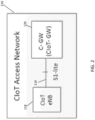
- CIoT access network 210 comprises CIoT eNB coupled with CIoT GW 120 via an S1-Lite interface 114.
- S1-Lite interface 114 comprises an S1-Lite C interface as defined in an architecture of CAN 210 as shown in and described with respect to FIG. 3 , below.
- FIG. 3 a diagram of a combined control plane-user plane control stack of a CAN in accordance with one or more embodiments will be discussed.
- the control plane comprises protocols for control and support of the user plane functions.
- the following control planes are used in a C1 interface/narrow band air interface Cellular IoT Terrestrial Radio Access Network (CITRAN) mode.
- CITRAN Cellular IoT Terrestrial Radio Access Network
- Uu may be analogous to the Evolved Universal Terrestrial Radio Access (E-UTRA) per a Long Term Evolution (LTE) air interface.
- E-UTRA Evolved Universal Terrestrial Radio Access
- LTE Long Term Evolution
- FIG. 3 shows the protocol stack for the control-plane comprising a Non-Access Stratum (NAS) Lite protocol layer 212 to couple CIoT UE 116 with CIoT GW 120 via CIoT eNB 118. Furthermore, CIoT UE 116 couples to CIoT eNB using the flowing layers. Radio Resource Control (RRC) layer 214, (PDCP) layer 216, Radio Link Control (RLC) layer 218, Media Access Control (MAC) layer 220, and physical (PHY) layer 222.
- RRC Radio Resource Control
- PDCP Radio Link Control
- RLC Radio Link Control
- MAC Media Access Control
- PHY physical
- RLC layer 218 and MAC layer are terminated in CIoT eNB 118 on the network side and perform the same functions as for the user plane.
- RRC layer 214 is terminated in CIoT eNB 118 on the network side and performs the following functions: Cellular Internet of Things Application Protocol (CIAP) Paging, RRC connection management, resource block (RB) control, and/or user equipment (UE) measurement reporting and control.
- the Non-Access Stratum (NAS)- Lite protocol layer is terminated in the CIoT GW 120 on the network side and performs reduced Non-Access Stratum (NAS) functions including: Last Seen timer updating, CIAP data message (CIAP_Data_Msg) handling, authentication, buffer handling, and security control.
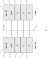
- S1 Lite interface 114 is the interface within the CIoT Access Gateway between CIoT GW 120 and CIoT UE 116.
- the application layer signaling protocol may be referred to as CIoT Application Protocol (CIoT AP) 410. Since potentially there may be billions of CIoT UE 116 devices sending messages, in the clean slate architecture an efficient way to provide congestion control may be to utilize a Stream Control Transmission Protocol (SCTP) 412 for signaling transport.
- SCTP 412 may be provided on top of internet protocol (IP) 414.
- a Layer 2 protocol 416 and a Layer 1 protocol 418 may be provided.
- the procedures for CIoT AP410 procedures are outlined in Table 1, below. Table 1: CIoT- AP Elementary Procedures CloT-AP Messages name Required for S1-Lite CIAP- PAGING NEEDED CIAP- SETUP NEEDED CIAP- SETUP RESPONSE NEEDED CIAP_DATA_MSG NEEDED LST (Last seen timer) UPDATE NEEDED LST (Last seen timer) CHECK NEEDED
- a CIAP setup request may be a message to configure a reduced signaling overhead between CIoT eNB 118 and CIoT GW 120 and/or between CIoT eNB 118 and CIoT UE 116.
- a reduced signaling overhead may refer to, for example, a low throughput or a very low throughput such as transmission of around one packet or very few packets at a frequency of around once per day or even less frequently, wherein the packet size may around 160 bytes or less as an example.
- the transmitting devices may have little or no mobility and therefore do not perform a handover, or very infrequently perform a handover.
- Such packets may be transmitted very infrequently or sometimes only in an emergency situation, and also may be transmitted with a low or very low transmission rate, for example around 180 kilohertz (kHz) or so.
- kHz kilohertz
- the CIAP SETUP REQUEST message 510 is an initial setup request message from CIoT GW 120 to CIoT eNB 118.
- the CIAP SETUP REQUEST message may contain a last seen timer information element (IE), the CIAP_Data_Msg Protocol Data Unit (PDU) IE, the Trace Activation IE, the Local Area Identity (LAI) IE, the CIoT UE Radio Capability IE, and/or the Subscriber Profile Identity (ID) for Radio Access Technology (RAT)/Frequency priority IE.
- the CIoT eNB 118 then provides a CIAP SETUP RESPONSE 512 to the CIoT GW 120.
- the CIAP setup request may be referred to as a Connection Establishment Procedure wherein the CIAP SETUP REQUEST message 510 may be referred to as an S1-AP connection establishment indication procedure.
- the Connection Establishment Indication procedure may enable the CIoT GW 120 and/or MME 122 to provide information to eNB 118 to complete the establishment of the UE-associated logical S1-connection after receiving an INITIAL UE MESSAGE message, for example if CIoT GW 120 and/or MME 122 has no non-access stratum (NAS) protocol data unit (PDU) to send in the downlink (DL) for Control Plane CIoT evolved packet system (EPS) Optimization.
- NAS non-access stratum
- PDU protocol data unit
- the capability of the UE 116 may be provided from the CIoT GW 120 and/or MME 122 to eNB 118 in this procedure, and may be included in a response or message analogous to CIAP SETUP RESPONSE 512. If the radio capability of UE 116 is not included, eNB 118 may be triggered to request the UE Radio Capability from UE 116 and to provide the UE Radio Capability to the CIoT GW 120 and/or MME 122 in a UE CAPABILITY INFO INDICATION message. Such a procedure may be initiated by the CIoT GW 120 and/or MME 122. It should be noted that the terminology and/or procedures are merely example implementations of a CIAP setup request or a Connection Establishment Procedure, and the scope of the claimed subject matter is not limited in these respects.
- the Service Request could either be a CIoT UE 116 originating request or a network originating request reporting related information element (IE).
- the flow in FIG. 6 includes CIoT UE 116, CIoT eNB 118, CIoT GW 120, Service Capability Server (SCS) 610, access server (AS) 140, and/or home subscriber server (HSS) 138.
- Last Seen Time (LST) may refer to a last timer update sent by CIoT UE 116 before going to sleep.
- the CIoT UE 116 sends a CIoT Non-Access Stratum (C-NAS) message Service Request towards CIoT GW 120 encapsulated in a radio resource control (RRC) message to CIoT eNB 118.
- the one or more RRC messages may be utilized to carry the CIoT temporary mobile subscriber identity (C-TMSI).
- the C-TMSI may comprise an encryption derived from the international mobile subscriber identity (IMSI) of CIoT UE 116 and may be referred to as a CIoT IMSI.
- CIoT eNB 118 then forwards the C-NAS message to CIoT GW 120.
- the NAS message may be encapsulated in a CIoT AP 410 comprising an Initial UE Message such as NAS message, E-UTRAN cell global identifier (ECGI) of the serving cell, a C-TMSI, a closed subscriber group identity (CSG ID), and/or a CSG access Mode.
- ECGI E-UTRAN cell global identifier
- CSG ID closed subscriber group identity
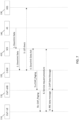
- FIG. 7 a diagram of an end-to-end message flow diagram of a CIoT access network triggered service request in accordance with one or more embodiments will be discussed.
- the downlink data mat be initiated by the application server (AS) 140 over an application programming (API) interface.
- AS application server
- API application programming
- CIoT GW 120 conducts a last seen time check for the destination CIoT UE 116 subscriber identity carried in the message. Based on this information, an estimated next wake time may be determined. The message then may be discarded or stored in a buffer of CIoT GW 120 based on this information element (IE).
- IE information element
- a downlink data acknowledgement may be sent to SCS 610 by CIoT GW 120. If SCS 610 does not receive a downlink data acknowledgement, then SCS 610 sends the downlink data message again after an expiry timer. Once CIoT GW 120 sends a downlink data acknowledgement to SCS 610, CIoT GW simultaneously pages CIoT eNB 118 which in turn pages CIoT UE 116.
- CIoT Gateway (CIoT GW) 120 may initiate the paging procedure by sending a CIAP-PAGING message 810 to CIoT eNB 118.
- paging may occur only during a network triggered service request, for example as shown in and described with respect to FIG. 7 , above.
- Paging may be implemented in accordance to an idle mode power saving mode (PSM).
- PSM power saving mode
- a tracking area update (TAU) accept and/or a routing area update (RAU) accept in CIoT related signaling may not be needed.
- IEs information elements
- Table 2 CIAP Paging Information Elements IE/Group Name Presence Message Type M CloT- UE Identity Index value M CloT- UE Paging Identity M CIAP- Paging eDRX O CIAP- Paging Priority O UE Radio Capability for Paging O
- a CIoT UE 116 could be a gateway that supports up to 1,024 CIoT UE 116 devices.
- a CIoT international mobile subscriber identity (C-IMSI) may be utilized for subscriber identification and may be stored in the subscriber identity module (SIM) card of CIoT UE 116.
- the C-IMSI may comprise a mobile country code (MCC) comprising 3 digits, a mobile network code (MNC) comprising 2 or 3 digits, and a CIoT subscription identification number (CSIN) comprising 14 or 15 digits.
- MCC mobile country code
- MNC mobile network code
- CSIN CIoT subscription identification number
- GSIN gateway subscriber identification number
- GSIN gateway subscriber identification number
- a CSIN may comprise a GSIN comprising 5 digits and a mobile subscriber identification number comprising 10 digits.
- the C- TMSI may have the size of 4 octets and may be allocated by CIoT GW 120.
- the C-TMSI information element (IE) may represent the identity with which CIoT UE 116 is paged according to Table 3, below. Table 3: CIoT UE Paging Identity IE/Group Name Presence CHOICE UE Paging Identity M >C-TMSI >>lMSI M
- a message flow diagram of a CIAP data message (CIAP_DATA MSG) in accordance with one or more embodiments will be discussed.
- the flow of a CIAP data message may be as follows: from CIoT GW 120 to CIoT eNB 118 at operation 910, and from CIoT eNB 118 to CIoT GW 120 at operation 912.
- the information elements for the CIAP data message are listed in Table 4, below.
- Table 4 CIAP Data Message Information Elements IE/Group Name Presence Range IE type and reference Semantics description Criticality Message Type M 2.4.1.1 YES C-GW CloT-UE ClAP ID M 2.4.1.2 YES CloT- eNB- UE ClAP ID M 2.4.1.3 YES CIAP_Data_Msg M YES Subscriber Profile ID for RAT/Frequency priority O 2.4.1.4 YES
- the Message Type Information Element uniquely identifies the message being sent, and may be mandatory for all messages in one or more embodiments.
- the IE type and reference is shown in Table 5, below.
- MME Mobility Management Entity
- UE User Equipment
- CIAP Cellular Internet of Things Application Protocol
- ID Identity
- MME UE CIAP ID uniquely identifies the UE association over the S1- Lite interface 114 within MME 122 as shown in Table 6, below: Table 6: MME UE CIAP ID IE/Group Name Presence Range IE type and reference Semantics description MME UE CIAP ID M INTEGER (0 .. 2 32 -1 )
- the CIoT evolved Node B (CIoT eNB) CIoT User Equipment (CIoT UE) Cellular Internet of Things Application Protocol (CIAP) Identity (ID) (CIoT eNB CIoT UE CIAP ID) uniquely identifies the UE association over the S1 interface 114 within the CIoT eNB 118 as shown in Table 7, below: Table 7: CIoT eNB CIoT UE CIAP ID IE/Group Name Presence Range IE type and reference Semantics description CloT- eNB CloT- UE CIAP ID M INTEGER (0 .. 2 24 -1)
- the Subscriber Profile Identity (ID) or (SPID) for Radio Access Technology (RAT)/Frequency Priority parameter received by the CIoT eNB 118 via the S1 Lite interface 114 may refer to user information, for example a service usage profile. Such information may be specific to a CIoT UE 116 and may apply to all the Radio Bearers of the CIoT UE 116. This index may be mapped by CIoT eNB 118 to a locally defined configuration in order to apply specific radio resource management (RRM) strategies, for example to define priorities of a radio resource control (RRC) idle (RRC_IDLE) mode.
- RRM radio resource management
- the Subscriber Profile ID information element (IE) for RAT/Frequency Selection Priority may utilized to define camp priorities in an Idle mode and to control inter-RAT/inter-frequency handovers in Active mode.
- the SPID IE is shown in Table 8, below. Table 8: SPID for RAT/Frequency Priority IE/Group Name Presence Range IE type and reference Semantics description Subscriber Profile ID for RAT/Frequency Priority M INTEGER (1..256)
- This message is sent by CIoT eNB 118 and may be utilized for carrying Non-Access Stratum (NAS) information over S1 Lite interface 114.
- the direction of flow for this message may be as follows: CIoT eNB 118 to MME 122 and/or CIoT GW 120.
- Table 9 CIoT Message Information Elements IE/Group Name Presence Range IE type and reference Semantics description Criticality Assigned Criticality Message Type M 2.4.1.1 YES ignore MME CloT UE CIAP ID M 2.4.1.2 YES reject CloT eNS- UE CIAP ID M 2.4.1.3 YES reject CIAP_Data_MSG M YES reject CITRAN CGI M YES ignore
- device 1000 may include application circuitry 1002, baseband circuitry 1004, Radio Frequency (RF) circuitry 1006, front-end module (FEM) circuitry 1008 and one or more antennas 1010, coupled together at least as shown.
- CIoT eNB CIoT evolved NodeB
- CIoT gateway CIoT gateway
- CIoT UE CIoT User Equipment
- device 1000 may include application circuitry 1002, baseband circuitry 1004, Radio Frequency (RF) circuitry 1006, front-end module (FEM) circuitry 1008 and one or more antennas 1010, coupled together at least as shown.
- RF Radio Frequency
- FEM front-end module
- the above described circuitries may be included in various devices, in whole or in part, for example an eNB or a GW according to a cloud-RAN (C-RAN) implementation, and the scope of the claimed subject matter is not limited in these respects.
- C-RAN cloud-RAN
- circuitry may refer to, be part of, or include an Application Specific Integrated Circuit (ASIC), an electronic circuit, a processor (shared, dedicated, or group), and/or memory (shared, dedicated, or group) that execute one or more software or firmware programs, a combinational logic circuit, and/or other suitable hardware components that provide the described functionality.
- ASIC Application Specific Integrated Circuit
- the circuitry may be implemented in, or functions associated with the circuitry may be implemented by, one or more software or firmware modules.
- circuitry may include logic, at least partially operable in hardware. Embodiments described herein may be implemented into a system using any suitably configured hardware and/or software.
- Application circuitry 1000 may include one or more application processors.
- application circuitry 1000 may include circuitry such as, but not limited to, one or more single-core or multi-core processors.
- the one or more processors may include any combination of general-purpose processors and dedicated processors, for example graphics processors, application processors, and so on.
- the processors may be coupled with and/or may include memory and/or storage and may be configured to execute instructions stored in the memory and/or storage to enable various applications and/or operating systems to run on the system.
- Baseband circuitry 1004 may include circuitry such as, but not limited to, one or more single-core or multi-core processors.
- Baseband circuitry 1004 may include one or more baseband processors and/or control logic to process baseband signals received from a receive signal path of RF circuitry 1006 and to generate baseband signals for a transmit signal path of the RF circuitry 1006.
- Baseband processing circuity 1004 may interface with the application circuitry 1002 for generation and processing of the baseband signals and for controlling operations of the RF circuitry 1006.
- the baseband circuitry 1004 may include a second generation (2G) baseband processor 1004a, third generation (3G) baseband processor 1004b, fourth generation (4G) baseband processor 1004c, and/or one or more other baseband processors 1004d for other existing generations, generations in development or to be developed in the future, for example fifth generation (5G), sixth generation (6G), and so on.
- Baseband circuitry 1004, for example one or more of baseband processors 1004a through 1004d may handle various radio control functions that enable communication with one or more radio networks via RF circuitry 1006.
- the radio control functions may include, but are not limited to, signal modulation and/or demodulation, encoding and/or decoding, radio frequency shifting, and so on.
- modulation and/or demodulation circuitry of baseband circuitry 1004 may include Fast-Fourier Transform (FFT), precoding, and/or constellation mapping and/or demapping functionality.
- FFT Fast-Fourier Transform
- encoding and/or decoding circuitry of baseband circuitry 1004 may include convolution, tail-biting convolution, turbo, Viterbi, and/or Low Density Parity Check (LDPC) encoder and/or decoder functionality.
- LDPC Low Density Parity Check
- baseband circuitry 1004 may include elements of a protocol stack such as, for example, elements of an evolved universal terrestrial radio access network (EUTRAN) protocol including, for example, physical (PHY), media access control (MAC), radio link control (RLC), packet data convergence protocol (PDCP), and/or radio resource control (RRC) elements.
- EUTRAN evolved universal terrestrial radio access network
- Processor 1004e of the baseband circuitry 1004 may be configured to run elements of the protocol stack for signaling of the PHY, MAC, RLC, PDCP and/or RRC layers.
- the baseband circuitry may include one or more audio digital signal processors (DSP) 1004f.
- DSP audio digital signal processors
- the one or more audio DSPs 1004f may include elements for compression and/or decompression and/or echo cancellation and may include other suitable processing elements in other embodiments.
- Components of the baseband circuitry may be suitably combined in a single chip, a single chipset, or disposed on a same circuit board in some embodiments.
- some or all of the constituent components of baseband circuitry 1004 and application circuitry 1002 may be implemented together such as, for example, on a system on a chip (SOC).
- SOC system on a chip
- baseband circuitry 1004 may provide for communication compatible with one or more radio technologies.
- baseband circuitry 1004 may support communication with an evolved universal terrestrial radio access network (EUTRAN) and/or other wireless metropolitan area networks (WMAN), a wireless local area network (WLAN), a wireless personal area network (WPAN).
- EUTRAN evolved universal terrestrial radio access network
- WMAN wireless metropolitan area networks
- WLAN wireless local area network
- WPAN wireless personal area network
- Embodiments in which baseband circuitry 1004 is configured to support radio communications of more than one wireless protocol may be referred to as multi-mode baseband circuitry.
- RF circuitry 1006 may enable communication with wireless networks using modulated electromagnetic radiation through a non-solid medium.
- RF circuitry 1006 may include switches, filters, amplifiers, and so on, to facilitate the communication with the wireless network.
- RF circuitry 1006 may include a receive signal path which may include circuitry to down-convert RF signals received from FEM circuitry 1008 and provide baseband signals to baseband circuitry 1004.
- RF circuitry 1006 may also include a transmit signal path which may include circuitry to up-convert baseband signals provided by the baseband circuitry 1004 and provide RF output signals to FEM circuitry 1008 for transmission.
- RF circuitry 1006 may include a receive signal path and a transmit signal path.
- the receive signal path of RF circuitry 1006 may include mixer circuitry 1006a, amplifier circuitry 1006b and filter circuitry 1006c.
- the transmit signal path of RF circuitry 1006 may include filter circuitry 1006c and mixer circuitry 1006a.
- RF circuitry 1006 may also include synthesizer circuitry 1006d for synthesizing a frequency for use by the mixer circuitry 1006a of the receive signal path and the transmit signal path.
- the mixer circuitry 1006a of the receive signal path may be configured to down-convert RF signals received from FEM circuitry 1008 based on the synthesized frequency provided by synthesizer circuitry 1006d.
- Amplifier circuitry 1006b may be configured to amplify the down-converted signals and the filter circuitry 1006c may be a low-pass filter (LPF) or band-pass filter (BPF) configured to remove unwanted signals from the down-converted signals to generate output baseband signals.
- Output baseband signals may be provided to baseband circuitry 1004 for further processing.
- the output baseband signals may be zero-frequency baseband signals, although this may be optional.
- mixer circuitry 1006a of the receive signal path may comprise passive mixers, although the scope of the embodiments is not limited in this respect.
- mixer circuitry 1006a of the transmit signal path may be configured to up-convert input baseband signals based on the synthesized frequency provided by synthesizer circuitry 1006d to generate RF output signals for FEM circuitry 1008.
- the baseband signals may be provided by the baseband circuitry 1004 and may be filtered by filter circuitry 1006c.
- Filter circuitry 1006c may include a low-pass filter (LPF), although the scope of the embodiments is not limited in this respect.
- LPF low-pass filter
- mixer circuitry 1006a of the receive signal path and the mixer circuitry 1006a of the transmit signal path may include two or more mixers and may be arranged for quadrature down conversion and/or up conversion respectively.
- mixer circuitry 1006a of the receive signal path and the mixer circuitry 1006a of the transmit signal path may include two or more mixers and may be arranged for image rejection, for example Hartley image rejection.
- mixer circuitry 1006a of the receive signal path and the mixer circuitry 1006a may be arranged for direct down conversion and/or direct up conversion, respectively.
- mixer circuitry 1006a of the receive signal path and mixer circuitry 1006a of the transmit signal path may be configured for super-heterodyne operation.
- the output baseband signals and the input baseband signals may be analog baseband signals, although the scope of the embodiments is not limited in this respect.
- the output baseband signals and the input baseband signals may be digital baseband signals.
- RF circuitry 1006 may include analog-to-digital converter (ADC) and digital-to-analog converter (DAC) circuitry
- baseband circuitry 1004 may include a digital baseband interface to communicate with RF circuitry 1006.
- ADC analog-to-digital converter
- DAC digital-to-analog converter
- baseband circuitry 1004 may include a digital baseband interface to communicate with RF circuitry 1006.
- separate radio integrated circuit (IC) circuitry may be provided for processing signals for one or more spectra, although the scope of the embodiments is not limited in this respect.
- synthesizer circuitry 1006d may be a fractional-N synthesizer or a fractional N/N+1 synthesizer, although the scope of the embodiments is not limited in this respect as other types of frequency synthesizers may be suitable.
- synthesizer circuitry 1006d may be a delta-sigma synthesizer, a frequency multiplier, or a synthesizer comprising a phase-locked loop with a frequency divider.
- Synthesizer circuitry 1006d may be configured to synthesize an output frequency for use by mixer circuitry 1006a of RF circuitry 1006 based on a frequency input and a divider control input. In some embodiments, synthesizer circuitry 1006d may be a fractional N/N+1 synthesizer.
- frequency input may be provided by a voltage controlled oscillator (VCO), although this may be optional.
- VCO voltage controlled oscillator
- Divider control input may be provided by either baseband circuitry 1004 or applications processor 1002 depending on the desired output frequency.
- a divider control input (e.g., N) may be determined from a look-up table based on a channel indicated by applications processor 1002.
- Synthesizer circuitry 1006d of RF circuitry 1006 may include a divider, a delay-locked loop (DLL), a multiplexer and a phase accumulator.
- the divider may be a dual modulus divider (DMD) and the phase accumulator may be a digital phase accumulator (DPA).
- DMD may be configured to divide the input signal by either N or N+1, for example based on a carry out, to provide a fractional division ratio.
- the DLL may include a set of cascaded, tunable, delay elements, a phase detector, a charge pump and a D-type flip-flop.
- the delay elements may be configured to break a VCO period up into Nd equal packets of phase, where Nd is the number of delay elements in the delay line.
- Nd is the number of delay elements in the delay line.
- synthesizer circuitry 1006d may be configured to generate a carrier frequency as the output frequency, while in other embodiments, the output frequency may be a multiple of the carrier frequency, for example twice the carrier frequency, four times the carrier frequency, and so on, and used in conjunction with quadrature generator and divider circuitry to generate multiple signals at the carrier frequency with multiple different phases with respect to each other.
- the output frequency may be a local oscillator (LO) frequency (fLO).
- RF circuitry 1006 may include an in-phase and quadrature (IQ) and/or polar converter.
- FEM circuitry 1008 may include a receive signal path which may include circuitry configured to operate on RF signals received from one or more antennas 710, amplify the received signals and provide the amplified versions of the received signals to the RF circuitry 1006 for further processing.
- FEM circuitry 1008 may also include a transmit signal path which may include circuitry configured to amplify signals for transmission provided by RF circuitry 1006 for transmission by one or more of the one or more antennas 1010.
- FEM circuitry 1008 may include a transmit/receive (TX/RX) switch to switch between transmit mode and receive mode operation.
- FEM circuitry 1008 may include a receive signal path and a transmit signal path.
- the receive signal path of FEM circuitry 1008 may include a low-noise amplifier (LNA) to amplify received RF signals and to provide the amplified received RF signals as an output, for example to RF circuitry 1006.
- the transmit signal path of FEM circuitry 1008 may include a power amplifier (PA) to amplify input RF signals, for example provided by RF circuitry 1006, and one or more filters to generate RF signals for subsequent transmission, for example by one or more of antennas 1010.
- device 1000 may include additional elements such as, for example, memory and/or storage, display, camera, sensor, and/or input/output (I/O) interface, although the scope of the claimed subject matter is not limited in this respect.
Landscapes
- Engineering & Computer Science (AREA)
- Computer Networks & Wireless Communication (AREA)
- Signal Processing (AREA)
- Computer Security & Cryptography (AREA)
- Health & Medical Sciences (AREA)
- Computing Systems (AREA)
- General Health & Medical Sciences (AREA)
- Medical Informatics (AREA)
- Mobile Radio Communication Systems (AREA)
Description
- The present application claims the benefit of
U.S. Application No. 62/204,848 (Attorney Docket No. P87994Z) filed Aug. 13, 2015 - The existing S1 Application Protocol (AP) interface in accordance with current Third Generation Partnership Project (3GPP) standards and existing S1 AP message procedures have high message overhead in addition to a large number of message procedures and information elements (IEs) elements that are not optimized to support Internet of Things (IoT) communications using a cellular network. The use cases for Cellular Internet of Things (CIoT) include gas meters, smart home sensors, industrial sensors and/or other applications which all form a part of Internet of Things. The evolution of the Internet of Things includes an estimated prediction of billions of CIoT user equipment (CIoT UE) devices and a clean slate architecture with optimal message procedures to ensure low signaling overhead than is currently available using exiting 3GPP standards, wherein the document "3rd Generation Partnership Project; Technical Specification Group Services and System Aspects; Architecture enhancements for Cellular Internet of Things; (Release 13)", 6 August 2015, is one of such standards.
- The invention is directed to a Cellular Internet of Things evolved Node B, CIoT eNB per
claim 1 and corresponding machine-readable storage including machine-readable instructions perclaim 7. Dependent claims describe preferred embodiments of the invention. The claimed subject matter may be understood by reference to the following detailed description when read with the accompanying drawings in which: -
FIG. 1 is a diagram of a Cellular Internet of Things (CIoT) architecture in accordance with one or more embodiments; -
FIG. 2 is a diagram of an S1-Lite interface in the Cellular Internet of Things (CIoT) Access Network (CAN) in accordance with one or more embodiments; -
FIG. 3 is a diagram of a combined control plane-user plane control stack of a CAN in accordance with one or more embodiments; -
FIG. 4 is a diagram of an S1-Lite interface in accordance with one or more embodiments; -
FIG. 5 is a message flow diagram of a Cellular Internet of Things Application Protocol (CIAP) setup request in accordance with one or more embodiments; -
FIG. 6 is a diagram of an end-to-end message flow diagram for a CIoT UE Service Request in accordance with one or more embodiments; -
FIG. 7 is a diagram of an end-to-end message flow diagram of a Cellular Internet of Things (CIoT) access network triggered service request in accordance with one or more embodiments; -
FIG. 8 is a message flow diagram of Cellular Internet of Things Application Protocol (CIAP) paging in accordance with one or more embodiments; -
FIG. 9 is a message flow diagram of a Cellular Internet of Things Application Protocol (CIAP) data message in accordance with one or more embodiments; and -
FIG. 10 is a diagram of example components of a wireless device in accordance with one or more embodiments. - It will be appreciated that for simplicity and/or clarity of illustration, elements illustrated in the figures have not necessarily been drawn to scale. For example, the dimensions of some of the elements may be exaggerated relative to other elements for clarity. Further, if considered appropriate, reference numerals have been repeated among the figures to indicate corresponding and/or analogous elements.
- In the following detailed description, numerous specific details are set forth to provide a thorough understanding of claimed subject matter. However, it will be understood by those skilled in the art that claimed subject matter may be practiced without these specific details. In other instances, well-known methods, procedures, components and/or circuits have not been described in detail.
- In the following description and/or claims, the terms coupled and/or connected, along with their derivatives, may be used. In particular embodiments, connected may be used to indicate that two or more elements are in direct physical and/or electrical contact with each other. Coupled may mean that two or more elements are in direct physical and/or electrical contact. Coupled, however, may also mean that two or more elements may not be in direct contact with each other, but yet may still cooperate and/or interact with each other. For example, "coupled" may mean that two or more elements do not contact each other but are indirectly joined together via another element or intermediate elements. Finally, the terms "on," "overlying," and "over" may be used in the following description and claims. "On," "overlying," and "over" may be used to indicate that two or more elements are in direct physical contact with each other. "Over", however, may also mean that two or more elements are not in direct contact with each other. For example, "over" may mean that one element is above another element but not contact each other and may have another element or elements in between the two elements. Furthermore, the term "and/or" may mean "and", it may mean "or", it may mean "exclusive-or", it may mean "one", it may mean "some, but not all", it may mean "neither", and/or it may mean "both", although the scope of claimed subject matter is not limited in this respect. In the following description and/or claims, the terms "comprise" and "include," along with their derivatives, may be used and are intended as synonyms for each other.
- Referring now to
FIG. 1 , a diagram of a cellular Internet of Things (CIoT) architecture in accordance with one or more embodiments will be discussed.FIG. 1 show acellular network 100 comprising an network operator'shome network 110 to couple to aservice provider network 112.Service provider network 112 may include a cloud security gateway (GW) 126 to couple tohome network 110 via the Internet 128, and acloud service network 130 to couple tohome network 110 via adata center fabric 132.Home network 110 may comprise a service capability exposure function (SCEF) 134, an authentication center (AUC) 136, a home subscriber server (HSS) 138, and/or an access server (AS) 140. - Network 100 may provide an S1-Lite
Interface 114 to serve CIoT User Equipment (UE) devices such as CIoT-UE 116 and/or other devices or gateways. As shown inFIG. 1 , S1-Lite Interface 114 may be disposed between CIoT evolved Node B (CIoT eNB) and CIoT access gateway (CIoT GW or C-GW) 120.CIoT gateway 120 may comprise a mobility management entity (MME) 112 and serving gateway (SGW) (not shown) in addition to a packet gateway (PGW) (not shown). In some embodiments, MME 112 may be integrated with CIoTGW 120, and in other embodiments CIoTGW 120 may comprise a separate entity, although the scope of the claimed subject matter is not limited in these respects. An S1 Lite-CInterface 124 may connect MME 122 and CIoT eNB 118, and an S1 Lite-U interface may be utilized for user plane communication between CIoT eNB 118 and the SGW of CIoTGW 120. As shown inFIG. 1 , S1 LiteInterface 114 may provide a clean slate solution for the architecture for a CIoT Access Network (CAN) in order to enable efficient utilization of the resource functions of a power-efficient CIoT-UE 116. An example of such a CAN is shown in and described with respect toFIG. 2 , below. - Referring now to
FIG. 2 , a diagram of an S1-Lite interface in a CIoT Access Network (CAN) in accordance with one or more embodiments will be discussed. As shown inFIG. 2 ,CIoT access network 210 comprises CIoT eNB coupled with CIoTGW 120 via an S1-Lite interface 114. In one or more embodiments, S1-Lite interface 114 comprises an S1-Lite C interface as defined in an architecture of CAN 210 as shown in and described with respect toFIG. 3 , below. - Referring now to
FIG. 3 , a diagram of a combined control plane-user plane control stack of a CAN in accordance with one or more embodiments will be discussed. In the clean slate architecture of CAN 210, there is no separate user plane as data is sent over a Non-Access Stratum (NAS) layer. In such an arrangement, the control plane comprises protocols for control and support of the user plane functions. Accordingly, the following control planes are used in a C1 interface/narrow band air interface Cellular IoT Terrestrial Radio Access Network (CITRAN) mode. In wherein Uu may be analogous to the Evolved Universal Terrestrial Radio Access (E-UTRA) per a Long Term Evolution (LTE) air interface. -
FIG. 3 shows the protocol stack for the control-plane comprising a Non-Access Stratum (NAS)Lite protocol layer 212 to couple CIoT UE 116 with CIoT GW 120 via CIoT eNB 118. Furthermore, CIoT UE 116 couples to CIoT eNB using the flowing layers. Radio Resource Control (RRC)layer 214, (PDCP)layer 216, Radio Link Control (RLC)layer 218, Media Access Control (MAC)layer 220, and physical (PHY)layer 222. ThePDCP layer 216 is terminated in CIoT eNB 118 on the network side and performs the functions listed for the control plane in security architecture, for example ciphering and integrity protection.RLC layer 218 and MAC layer are terminated in CIoT eNB 118 on the network side and perform the same functions as for the user plane.RRC layer 214 is terminated in CIoT eNB 118 on the network side and performs the following functions: Cellular Internet of Things Application Protocol (CIAP) Paging, RRC connection management, resource block (RB) control, and/or user equipment (UE) measurement reporting and control. The Non-Access Stratum (NAS)- Lite protocol layer is terminated in the CIoTGW 120 on the network side and performs reduced Non-Access Stratum (NAS) functions including: Last Seen timer updating, CIAP data message (CIAP_Data_Msg) handling, authentication, buffer handling, and security control. - Referring now to
FIG. 4 , a diagram of an S1-Lite interface in accordance with one or more embodiments will be discussed. As shown in FIG,S1 Lite interface 114 is the interface within the CIoT Access Gateway betweenCIoT GW 120 andCIoT UE 116. OnS1 Lite interface 114, the application layer signaling protocol may be referred to as CIoT Application Protocol (CIoT AP) 410. Since potentially there may be billions ofCIoT UE 116 devices sending messages, in the clean slate architecture an efficient way to provide congestion control may be to utilize a Stream Control Transmission Protocol (SCTP) 412 for signaling transport. In one example,SCTP 412 may be provided on top of internet protocol (IP) 414. In addition, aLayer 2protocol 416 and aLayer 1protocol 418 may be provided. In one or more embodiments, the procedures for CIoT AP410 procedures are outlined in Table 1, below.Table 1: CIoT- AP Elementary Procedures CloT-AP Messages name Required for S1-Lite CIAP- PAGING NEEDED CIAP- SETUP NEEDED CIAP- SETUP RESPONSE NEEDED CIAP_DATA_MSG NEEDED LST (Last seen timer) UPDATE NEEDED LST (Last seen timer) CHECK NEEDED - Referring now to
FIG. 5 , a message flow diagram of a Cellular Internet of Things Application Protocol (CIAP) setup request in accordance with one or more embodiments will be discussed. A CIAP setup request may be a message to configure a reduced signaling overhead betweenCIoT eNB 118 andCIoT GW 120 and/or betweenCIoT eNB 118 andCIoT UE 116. A reduced signaling overhead may refer to, for example, a low throughput or a very low throughput such as transmission of around one packet or very few packets at a frequency of around once per day or even less frequently, wherein the packet size may around 160 bytes or less as an example. Typically, with a reduced signaling overhead arrangement, the transmitting devices may have little or no mobility and therefore do not perform a handover, or very infrequently perform a handover. Such packets may be transmitted very infrequently or sometimes only in an emergency situation, and also may be transmitted with a low or very low transmission rate, for example around 180 kilohertz (kHz) or so. It should be noted that these are merely example characteristics of a reduced signaling overhead, and the scope of the claimed subject matter is not limited in these respects. The following CIoT-AP 410 procedures may be utilized in a CIoT Clean Slate Architecture. As shown inFIG 5 , the CIAPSETUP REQUEST message 510 is an initial setup request message fromCIoT GW 120 toCIoT eNB 118. The CIAP SETUP REQUEST message may contain a last seen timer information element (IE), the CIAP_Data_Msg Protocol Data Unit (PDU) IE, the Trace Activation IE, the Local Area Identity (LAI) IE, the CIoT UE Radio Capability IE, and/or the Subscriber Profile Identity (ID) for Radio Access Technology (RAT)/Frequency priority IE. TheCIoT eNB 118 then provides aCIAP SETUP RESPONSE 512 to theCIoT GW 120. - In one or more embodiments, the CIAP setup request may be referred to as a Connection Establishment Procedure wherein the CIAP
SETUP REQUEST message 510 may be referred to as an S1-AP connection establishment indication procedure. In such embodiments, the Connection Establishment Indication procedure may enable theCIoT GW 120 and/orMME 122 to provide information toeNB 118 to complete the establishment of the UE-associated logical S1-connection after receiving an INITIAL UE MESSAGE message, for example ifCIoT GW 120 and/orMME 122 has no non-access stratum (NAS) protocol data unit (PDU) to send in the downlink (DL) for Control Plane CIoT evolved packet system (EPS) Optimization. The capability of the UE 116 (UE Radio Capability) may be provided from theCIoT GW 120 and/orMME 122 toeNB 118 in this procedure, and may be included in a response or message analogous toCIAP SETUP RESPONSE 512. If the radio capability ofUE 116 is not included,eNB 118 may be triggered to request the UE Radio Capability fromUE 116 and to provide the UE Radio Capability to theCIoT GW 120 and/orMME 122 in a UE CAPABILITY INFO INDICATION message. Such a procedure may be initiated by theCIoT GW 120 and/orMME 122. It should be noted that the terminology and/or procedures are merely example implementations of a CIAP setup request or a Connection Establishment Procedure, and the scope of the claimed subject matter is not limited in these respects. - Referring now to
FIG. 6 , a diagram of an end-to-end message flow diagram for a CIoT UE Service Request in accordance with one or more embodiments will be discussed. The Service Request could either be aCIoT UE 116 originating request or a network originating request reporting related information element (IE). The flow inFIG. 6 includesCIoT UE 116,CIoT eNB 118,CIoT GW 120, Service Capability Server (SCS) 610, access server (AS) 140, and/or home subscriber server (HSS) 138. In the diagram, Last Seen Time (LST) may refer to a last timer update sent byCIoT UE 116 before going to sleep. For aCIoT UE 116 triggered Service Request as shown inFIG. 6 , theCIoT UE 116 sends a CIoT Non-Access Stratum (C-NAS) message Service Request towardsCIoT GW 120 encapsulated in a radio resource control (RRC) message toCIoT eNB 118. The one or more RRC messages may be utilized to carry the CIoT temporary mobile subscriber identity (C-TMSI). The C-TMSI may comprise an encryption derived from the international mobile subscriber identity (IMSI) ofCIoT UE 116 and may be referred to as a CIoT IMSI.CIoT eNB 118 then forwards the C-NAS message toCIoT GW 120. The NAS message may be encapsulated in aCIoT AP 410 comprising an Initial UE Message such as NAS message, E-UTRAN cell global identifier (ECGI) of the serving cell, a C-TMSI, a closed subscriber group identity (CSG ID), and/or a CSG access Mode. IfCIoT GW 120 is unable to handle the Service Request, thenCIoT GW 120 will reject the Service Request. - Referring now to
FIG. 7 , a diagram of an end-to-end message flow diagram of a CIoT access network triggered service request in accordance with one or more embodiments will be discussed. With a CIoT Access Network Triggered Service Request as shown inFIG. 7 , the downlink data mat be initiated by the application server (AS) 140 over an application programming (API) interface. Once the downlink data is received byCIoT GW 120, thenCIoT GW 120 conducts a last seen time check for thedestination CIoT UE 116 subscriber identity carried in the message. Based on this information, an estimated next wake time may be determined. The message then may be discarded or stored in a buffer ofCIoT GW 120 based on this information element (IE). If the incoming message is not discarded, a downlink data acknowledgement may be sent toSCS 610 byCIoT GW 120. IfSCS 610 does not receive a downlink data acknowledgement, thenSCS 610 sends the downlink data message again after an expiry timer. OnceCIoT GW 120 sends a downlink data acknowledgement toSCS 610, CIoT GW simultaneously pagesCIoT eNB 118 which in turnpages CIoT UE 116. - Referring now to
FIG. 8 , a message flow diagram of CIAP paging in accordance with one or more embodiments will be discussed. As shown inFIG. 8 , CIoT Gateway (CIoT GW) 120 may initiate the paging procedure by sending a CIAP-PAGING message 810 toCIoT eNB 118. In some embodiments, paging may occur only during a network triggered service request, for example as shown in and described with respect toFIG. 7 , above. Paging may be implemented in accordance to an idle mode power saving mode (PSM). In some embodiments, a tracking area update (TAU) accept and/or a routing area update (RAU) accept in CIoT related signaling may not be needed. As a result, a TAU request or a RAU request will not be involved with the signaling procedures. The following information elements (IEs) may be involved with CIAP Paging as shown in Table 2, below.Table 2: CIAP Paging Information Elements IE/Group Name Presence Message Type M CloT- UE Identity Index value M CloT- UE Paging Identity M CIAP- Paging eDRX O CIAP- Paging Priority O UE Radio Capability for Paging O - For CIoT UE Paging Identity, a
CIoT UE 116 could be a gateway that supports up to 1,024CIoT UE 116 devices. A CIoT international mobile subscriber identity (C-IMSI) may be utilized for subscriber identification and may be stored in the subscriber identity module (SIM) card ofCIoT UE 116. The C-IMSI may comprise a mobile country code (MCC) comprising 3 digits, a mobile network code (MNC) comprising 2 or 3 digits, and a CIoT subscription identification number (CSIN) comprising 14 or 15 digits. Furthermore, a gateway subscriber identification number (GSIN) may identifyCIoT GW 120. Thus, a CSIN may comprise a GSIN comprising 5 digits and a mobile subscriber identification number comprising 10 digits. The C- TMSI may have the size of 4 octets and may be allocated byCIoT GW 120. The C-TMSI information element (IE) may represent the identity with whichCIoT UE 116 is paged according to Table 3, below.Table 3: CIoT UE Paging Identity IE/Group Name Presence CHOICE UE Paging Identity M >C-TMSI >>lMSI M - Referring now to
FIG. 9 , a message flow diagram of a CIAP data message (CIAP_DATA MSG) in accordance with one or more embodiments will be discussed. The flow of a CIAP data message may be as follows: fromCIoT GW 120 toCIoT eNB 118 atoperation 910, and fromCIoT eNB 118 toCIoT GW 120 atoperation 912. The information elements for the CIAP data message are listed in Table 4, below.Table 4: CIAP Data Message Information Elements IE/Group Name Presence Range IE type and reference Semantics description Criticality Message Type M 2.4.1.1 YES C-GW CloT-UE ClAP ID M 2.4.1.2 YES CloT- eNB- UE ClAP ID M 2.4.1.3 YES CIAP_Data_Msg M YES Subscriber Profile ID for RAT/Frequency priority O 2.4.1.4 YES - The Message Type Information Element (IE) uniquely identifies the message being sent, and may be mandatory for all messages in one or more embodiments. The IE type and reference is shown in Table 5, below.
Table 5: Information Element Type and Reference IE/Group Name Presence IE type and reference Message Type >Procedure Code M (CIAP Setup, Paging, CIAP_DATA_MSG transport, Initial UE Message, Reset, Error Indication, CIAP_DATA Non Delivery Indication, CloT-UE Capability Info Indication, Deactivate Trace, Trace Start, Trace Failure Indication, CloT- eNB Configuration Update, CGW Configuration Update, Location Reporting Control, Location Reporting Failure Indication, Location Report, Overload Start, Overload Stop, Write-Replace Warning, CloT- eNB Direct Information Transfer, C-GW Direct Information Transfer, Cell Traffic Trace, CloT- eNB Configuration Transfer, CGW Configuration Transfer, Kill, CloT-UE Radio Capability Match, PWS restart Indication - The Mobility Management Entity (MME) User Equipment (UE) Cellular Internet of Things Application Protocol (CIAP) Identity (ID) (MME UE CIAP ID) uniquely identifies the UE association over the S1-
Lite interface 114 withinMME 122 as shown in Table 6, below:Table 6: MME UE CIAP ID IE/Group Name Presence Range IE type and reference Semantics description MME UE CIAP ID M INTEGER (0 .. 232 -1 ) - The CIoT evolved Node B (CIoT eNB) CIoT User Equipment (CIoT UE) Cellular Internet of Things Application Protocol (CIAP) Identity (ID) (CIoT eNB CIoT UE CIAP ID) uniquely identifies the UE association over the
S1 interface 114 within theCIoT eNB 118 as shown in Table 7, below:Table 7: CIoT eNB CIoT UE CIAP ID IE/Group Name Presence Range IE type and reference Semantics description CloT- eNB CloT- UE CIAP ID M INTEGER (0 .. 224-1) - In one or more embodiments, the Subscriber Profile Identity (ID) or (SPID) for Radio Access Technology (RAT)/Frequency Priority parameter received by the
CIoT eNB 118 via theS1 Lite interface 114 may refer to user information, for example a service usage profile. Such information may be specific to aCIoT UE 116 and may apply to all the Radio Bearers of theCIoT UE 116. This index may be mapped byCIoT eNB 118 to a locally defined configuration in order to apply specific radio resource management (RRM) strategies, for example to define priorities of a radio resource control (RRC) idle (RRC_IDLE) mode. The Subscriber Profile ID information element (IE) for RAT/Frequency Selection Priority may utilized to define camp priorities in an Idle mode and to control inter-RAT/inter-frequency handovers in Active mode. The SPID IE is shown in Table 8, below.Table 8: SPID for RAT/Frequency Priority IE/Group Name Presence Range IE type and reference Semantics description Subscriber Profile ID for RAT/Frequency Priority M INTEGER (1..256) - This message is sent by
CIoT eNB 118 and may be utilized for carrying Non-Access Stratum (NAS) information overS1 Lite interface 114. The direction of flow for this message may be as follows:CIoT eNB 118 toMME 122 and/orCIoT GW 120. The information elements for this message are shown in Table 9, below:Table 9: CIoT Message Information Elements IE/Group Name Presence Range IE type and reference Semantics description Criticality Assigned Criticality Message Type M 2.4.1.1 YES ignore MME CloT UE CIAP ID M 2.4.1.2 YES reject CloT eNS- UE CIAP ID M 2.4.1.3 YES reject CIAP_Data_MSG M YES reject CITRAN CGI M YES ignore - Referring now to
FIG. 10 , example components of a wireless device such as a CIoT evolved NodeB (CIoT eNB) device, a CIoT gateway (CIoT GW) device, or a CIoT User Equipment (CIoT UE) device in accordance with one or more embodiments will be discussed. In some embodiments,device 1000 may includeapplication circuitry 1002,baseband circuitry 1004, Radio Frequency (RF)circuitry 1006, front-end module (FEM)circuitry 1008 and one ormore antennas 1010, coupled together at least as shown. In other embodiments, the above described circuitries may be included in various devices, in whole or in part, for example an eNB or a GW according to a cloud-RAN (C-RAN) implementation, and the scope of the claimed subject matter is not limited in these respects. - As used herein, the term "circuitry" may refer to, be part of, or include an Application Specific Integrated Circuit (ASIC), an electronic circuit, a processor (shared, dedicated, or group), and/or memory (shared, dedicated, or group) that execute one or more software or firmware programs, a combinational logic circuit, and/or other suitable hardware components that provide the described functionality. In some embodiments, the circuitry may be implemented in, or functions associated with the circuitry may be implemented by, one or more software or firmware modules. In some embodiments, circuitry may include logic, at least partially operable in hardware. Embodiments described herein may be implemented into a system using any suitably configured hardware and/or software.
-
Application circuitry 1000 may include one or more application processors. For example,application circuitry 1000 may include circuitry such as, but not limited to, one or more single-core or multi-core processors. The one or more processors may include any combination of general-purpose processors and dedicated processors, for example graphics processors, application processors, and so on. The processors may be coupled with and/or may include memory and/or storage and may be configured to execute instructions stored in the memory and/or storage to enable various applications and/or operating systems to run on the system. -
Baseband circuitry 1004 may include circuitry such as, but not limited to, one or more single-core or multi-core processors.Baseband circuitry 1004 may include one or more baseband processors and/or control logic to process baseband signals received from a receive signal path ofRF circuitry 1006 and to generate baseband signals for a transmit signal path of theRF circuitry 1006.Baseband processing circuity 1004 may interface with theapplication circuitry 1002 for generation and processing of the baseband signals and for controlling operations of theRF circuitry 1006. For example, in some embodiments, thebaseband circuitry 1004 may include a second generation (2G) baseband processor 1004a, third generation (3G) baseband processor 1004b, fourth generation (4G) baseband processor 1004c, and/or one or more other baseband processors 1004d for other existing generations, generations in development or to be developed in the future, for example fifth generation (5G), sixth generation (6G), and so on.Baseband circuitry 1004, for example one or more of baseband processors 1004a through 1004d, may handle various radio control functions that enable communication with one or more radio networks viaRF circuitry 1006. The radio control functions may include, but are not limited to, signal modulation and/or demodulation, encoding and/or decoding, radio frequency shifting, and so on. In some embodiments, modulation and/or demodulation circuitry ofbaseband circuitry 1004 may include Fast-Fourier Transform (FFT), precoding, and/or constellation mapping and/or demapping functionality. In some embodiments, encoding and/or decoding circuitry ofbaseband circuitry 1004 may include convolution, tail-biting convolution, turbo, Viterbi, and/or Low Density Parity Check (LDPC) encoder and/or decoder functionality. Embodiments of modulation and/or demodulation and encoder and/or decoder functionality are not limited to these examples and may include other suitable functionality in other embodiments. - In some embodiments,
baseband circuitry 1004 may include elements of a protocol stack such as, for example, elements of an evolved universal terrestrial radio access network (EUTRAN) protocol including, for example, physical (PHY), media access control (MAC), radio link control (RLC), packet data convergence protocol (PDCP), and/or radio resource control (RRC) elements. Processor 1004e of thebaseband circuitry 1004 may be configured to run elements of the protocol stack for signaling of the PHY, MAC, RLC, PDCP and/or RRC layers. In some embodiments, the baseband circuitry may include one or more audio digital signal processors (DSP) 1004f. The one ormore audio DSPs 1004f may include elements for compression and/or decompression and/or echo cancellation and may include other suitable processing elements in other embodiments. Components of the baseband circuitry may be suitably combined in a single chip, a single chipset, or disposed on a same circuit board in some embodiments. In some embodiments, some or all of the constituent components ofbaseband circuitry 1004 andapplication circuitry 1002 may be implemented together such as, for example, on a system on a chip (SOC). - In some embodiments,
baseband circuitry 1004 may provide for communication compatible with one or more radio technologies. For example, in some embodiments,baseband circuitry 1004 may support communication with an evolved universal terrestrial radio access network (EUTRAN) and/or other wireless metropolitan area networks (WMAN), a wireless local area network (WLAN), a wireless personal area network (WPAN). Embodiments in whichbaseband circuitry 1004 is configured to support radio communications of more than one wireless protocol may be referred to as multi-mode baseband circuitry. -
RF circuitry 1006 may enable communication with wireless networks using modulated electromagnetic radiation through a non-solid medium. In various embodiments,RF circuitry 1006 may include switches, filters, amplifiers, and so on, to facilitate the communication with the wireless network.RF circuitry 1006 may include a receive signal path which may include circuitry to down-convert RF signals received fromFEM circuitry 1008 and provide baseband signals tobaseband circuitry 1004.RF circuitry 1006 may also include a transmit signal path which may include circuitry to up-convert baseband signals provided by thebaseband circuitry 1004 and provide RF output signals toFEM circuitry 1008 for transmission. - In some embodiments,
RF circuitry 1006 may include a receive signal path and a transmit signal path. The receive signal path ofRF circuitry 1006 may include mixer circuitry 1006a, amplifier circuitry 1006b and filter circuitry 1006c. The transmit signal path ofRF circuitry 1006 may include filter circuitry 1006c and mixer circuitry 1006a.RF circuitry 1006 may also include synthesizer circuitry 1006d for synthesizing a frequency for use by the mixer circuitry 1006a of the receive signal path and the transmit signal path. In some embodiments, the mixer circuitry 1006a of the receive signal path may be configured to down-convert RF signals received fromFEM circuitry 1008 based on the synthesized frequency provided by synthesizer circuitry 1006d. Amplifier circuitry 1006b may be configured to amplify the down-converted signals and the filter circuitry 1006c may be a low-pass filter (LPF) or band-pass filter (BPF) configured to remove unwanted signals from the down-converted signals to generate output baseband signals. Output baseband signals may be provided tobaseband circuitry 1004 for further processing. In some embodiments, the output baseband signals may be zero-frequency baseband signals, although this may be optional. In some embodiments, mixer circuitry 1006a of the receive signal path may comprise passive mixers, although the scope of the embodiments is not limited in this respect. - In some embodiments, mixer circuitry 1006a of the transmit signal path may be configured to up-convert input baseband signals based on the synthesized frequency provided by synthesizer circuitry 1006d to generate RF output signals for
FEM circuitry 1008. The baseband signals may be provided by thebaseband circuitry 1004 and may be filtered by filter circuitry 1006c. Filter circuitry 1006c may include a low-pass filter (LPF), although the scope of the embodiments is not limited in this respect. - In some embodiments, mixer circuitry 1006a of the receive signal path and the mixer circuitry 1006a of the transmit signal path may include two or more mixers and may be arranged for quadrature down conversion and/or up conversion respectively. In some embodiments, mixer circuitry 1006a of the receive signal path and the mixer circuitry 1006a of the transmit signal path may include two or more mixers and may be arranged for image rejection, for example Hartley image rejection. In some embodiments, mixer circuitry 1006a of the receive signal path and the mixer circuitry 1006a may be arranged for direct down conversion and/or direct up conversion, respectively. In some embodiments, mixer circuitry 1006a of the receive signal path and mixer circuitry 1006a of the transmit signal path may be configured for super-heterodyne operation.
- In some embodiments, the output baseband signals and the input baseband signals may be analog baseband signals, although the scope of the embodiments is not limited in this respect. In some alternate embodiments, the output baseband signals and the input baseband signals may be digital baseband signals. In these alternate embodiments,
RF circuitry 1006 may include analog-to-digital converter (ADC) and digital-to-analog converter (DAC) circuitry, andbaseband circuitry 1004 may include a digital baseband interface to communicate withRF circuitry 1006. In some dual-mode embodiments, separate radio integrated circuit (IC) circuitry may be provided for processing signals for one or more spectra, although the scope of the embodiments is not limited in this respect. - In some embodiments, synthesizer circuitry 1006d may be a fractional-N synthesizer or a fractional N/N+1 synthesizer, although the scope of the embodiments is not limited in this respect as other types of frequency synthesizers may be suitable. For example, synthesizer circuitry 1006d may be a delta-sigma synthesizer, a frequency multiplier, or a synthesizer comprising a phase-locked loop with a frequency divider.
- Synthesizer circuitry 1006d may be configured to synthesize an output frequency for use by mixer circuitry 1006a of
RF circuitry 1006 based on a frequency input and a divider control input. In some embodiments, synthesizer circuitry 1006d may be a fractional N/N+1 synthesizer. - In some embodiments, frequency input may be provided by a voltage controlled oscillator (VCO), although this may be optional. Divider control input may be provided by either
baseband circuitry 1004 orapplications processor 1002 depending on the desired output frequency. In some embodiments, a divider control input (e.g., N) may be determined from a look-up table based on a channel indicated byapplications processor 1002. - Synthesizer circuitry 1006d of
RF circuitry 1006 may include a divider, a delay-locked loop (DLL), a multiplexer and a phase accumulator. In some embodiments, the divider may be a dual modulus divider (DMD) and the phase accumulator may be a digital phase accumulator (DPA). In some embodiments, the DMD may be configured to divide the input signal by either N or N+1, for example based on a carry out, to provide a fractional division ratio. In some example embodiments, the DLL may include a set of cascaded, tunable, delay elements, a phase detector, a charge pump and a D-type flip-flop. In these embodiments, the delay elements may be configured to break a VCO period up into Nd equal packets of phase, where Nd is the number of delay elements in the delay line. In this way, the DLL provides negative feedback to help ensure that the total delay through the delay line is one VCO cycle. - In some embodiments, synthesizer circuitry 1006d may be configured to generate a carrier frequency as the output frequency, while in other embodiments, the output frequency may be a multiple of the carrier frequency, for example twice the carrier frequency, four times the carrier frequency, and so on, and used in conjunction with quadrature generator and divider circuitry to generate multiple signals at the carrier frequency with multiple different phases with respect to each other. In some embodiments, the output frequency may be a local oscillator (LO) frequency (fLO). In some embodiments,
RF circuitry 1006 may include an in-phase and quadrature (IQ) and/or polar converter. -
FEM circuitry 1008 may include a receive signal path which may include circuitry configured to operate on RF signals received from one or more antennas 710, amplify the received signals and provide the amplified versions of the received signals to theRF circuitry 1006 for further processing.FEM circuitry 1008 may also include a transmit signal path which may include circuitry configured to amplify signals for transmission provided byRF circuitry 1006 for transmission by one or more of the one ormore antennas 1010. - In some embodiments,
FEM circuitry 1008 may include a transmit/receive (TX/RX) switch to switch between transmit mode and receive mode operation.FEM circuitry 1008 may include a receive signal path and a transmit signal path. The receive signal path ofFEM circuitry 1008 may include a low-noise amplifier (LNA) to amplify received RF signals and to provide the amplified received RF signals as an output, for example toRF circuitry 1006. The transmit signal path ofFEM circuitry 1008 may include a power amplifier (PA) to amplify input RF signals, for example provided byRF circuitry 1006, and one or more filters to generate RF signals for subsequent transmission, for example by one or more ofantennas 1010. In some embodiments,device 1000 may include additional elements such as, for example, memory and/or storage, display, camera, sensor, and/or input/output (I/O) interface, although the scope of the claimed subject matter is not limited in this respect.
Claims (7)
- A Cellular Internet of Things evolved Node B, CIoT eNB (118) comprising baseband processing circuity including one or more processors to:process a Cellular Internet of Things Application Protocol, CIAP, setup request message received from a CIoT gateway, CIoT GW (120), the CIoT GW (120) comprising a mobility management entity, MME, a serving gateway node, SGW, and a packet gateway node, PGW, wherein the CIAP setup request message is to configure a reduced signaling overhead between the CIoT eNB (118) and the CIoT GW (120), or between the CIoT eNB (118) and a CIoT user equipment, UE (116), or a combination thereof;generate a CIAP setup response message to be transmitted to the CIoT GW (120) in response to the CIAP setup request message,wherein the CIAP setup request message and the CIAP response message are transmitted between the CIoT eNB (118) and the CIoT GW (120), wherein the CIAP setup request message and the CIAP response message are transmitted via an S1 Lite (114) interface between the CIoT eNB (118) and the CIoT GW (120),wherein the S1 Lite (114) interface comprises a control plane that includes user plane functions, andwherein when the CIAP setup response message does not include user equipment, UE, radio capability information for a UE, the one or more processors are further configured to:generate a UE radio capabilityinformation request message to be transmitted to the UE;provide the UE Radio Capability to the CloT GW (120).
- The CIoT eNB (118) as claimed in claim 1, wherein the baseband processing circuitry is configured to generate a Non-Access Stratum, NAS, Lite (212) service request message to be transmitted to the CIoT GW (120).
- The CIoT eNB (118) as claimed in any of claims 1-2, wherein the baseband processing circuity is configured to generate a CIAP data message to be transmitted to the CIoT GW (120).
- The CIoT eNB (118) as claimed in in any of claims 1-3, wherein the baseband processing circuitry is configured to generate a CIAP setup complete message to be transmitted to the CIoT GW (120) upon completion of configuration of a CIAP setup.
- The CIoT eNB (118) as claimed in any of claims 1-4, wherein the baseband processing circuitry is configured to process a last seen timer, LST, acknowledgment message received from a service capability server, SCS.
- The CIoT eNB (118) as claimed in any of claims 1-5, wherein the CIAP setup request message comprises a Connection Establishment Indication procedure.
- Machine-readable storage including machine-readable instructions, when executed, to implement an apparatus as claimed in any preceding claim.
Applications Claiming Priority (2)
| Application Number | Priority Date | Filing Date | Title |
|---|---|---|---|
| US201562204848P | 2015-08-13 | 2015-08-13 | |
| PCT/US2016/041043 WO2017027124A1 (en) | 2015-08-13 | 2016-07-06 | Lightweight s-1 lite protocol design for cellular internet of things |
Publications (2)
| Publication Number | Publication Date |
|---|---|
| EP3335401A1 EP3335401A1 (en) | 2018-06-20 |
| EP3335401B1 true EP3335401B1 (en) | 2025-02-12 |
Family
ID=56561454
Family Applications (1)
| Application Number | Title | Priority Date | Filing Date |
|---|---|---|---|
| EP16745920.5A Active EP3335401B1 (en) | 2015-08-13 | 2016-07-06 | Lightweight s-1 lite protocol design for cellular internet of things |
Country Status (5)
| Country | Link |
|---|---|
| US (1) | US11510094B2 (en) |
| EP (1) | EP3335401B1 (en) |
| CN (1) | CN107852424B (en) |
| HK (1) | HK1252002A1 (en) |
| WO (1) | WO2017027124A1 (en) |
Families Citing this family (1)
| Publication number | Priority date | Publication date | Assignee | Title |
|---|---|---|---|---|
| CN107852424B (en) | 2015-08-13 | 2021-01-22 | 苹果公司 | Lightweight S-1 Lite Protocol Design for Cellular IoT |
Family Cites Families (68)
| Publication number | Priority date | Publication date | Assignee | Title |
|---|---|---|---|---|
| EP3432504B1 (en) * | 2007-10-30 | 2021-06-23 | Nokia Technologies Oy | Methods, apparatuses, system and related computer program product for resource allocation |
| EP2096804A1 (en) * | 2008-02-27 | 2009-09-02 | Nokia Siemens Networks Oy | Inter-network-nodes flow control |
| GB0912944D0 (en) * | 2009-07-24 | 2009-09-02 | Vodafone Plc | SMS over lte sgs interface optimisations |
| US20110019776A1 (en) * | 2009-07-24 | 2011-01-27 | Interdigital Patent Holdings, Inc. | Method and apparatus for obtaining port index information |
| CN102804738B (en) | 2010-03-01 | 2016-10-19 | 交互数字专利控股公司 | Machine-to-Machine Gateway Architecture and Functionality |
| CN102111847B (en) | 2011-01-10 | 2013-07-24 | 大唐移动通信设备有限公司 | Access control method and device |
| JP5357913B2 (en) * | 2011-03-24 | 2013-12-04 | 株式会社エヌ・ティ・ティ・ドコモ | Mobile communication method |
| WO2012103737A1 (en) * | 2011-07-01 | 2012-08-09 | 华为技术有限公司 | Method and device for processing bearer |
| US20130343477A9 (en) * | 2011-11-04 | 2013-12-26 | Research In Motion Limited | PUSCH Reference Signal Design for High Doppler Frequency |
| CN103139125B (en) * | 2011-12-02 | 2016-04-13 | 华为技术有限公司 | Downlink data sending, receiving method and base station and user terminal |
| CN107257275B (en) * | 2012-01-27 | 2021-03-16 | 交互数字专利控股公司 | Method for ePDCCH performed by WTRU, WTRU, search space monitoring method and UE |
| WO2013161233A1 (en) * | 2012-04-26 | 2013-10-31 | 日本電気株式会社 | Wireless communication device, network node, user node, core network, and method mounted thereto |
| WO2013161798A1 (en) * | 2012-04-27 | 2013-10-31 | 三菱電機株式会社 | Communication system |
| US8995592B2 (en) * | 2012-05-10 | 2015-03-31 | Futurewei Technologies, Inc. | Signaling to support advanced wireless receivers and related devices and methods |
| GB2504524A (en) | 2012-08-01 | 2014-02-05 | Nec Corp | Determining a set of cells in which to transmit a paging message for a mobile device |
| WO2014069895A1 (en) * | 2012-10-31 | 2014-05-08 | 엘지전자 주식회사 | Method and device for receiving control information in wireless communication system |
| JP6378192B2 (en) * | 2012-11-13 | 2018-08-22 | エルジー エレクトロニクス インコーポレイティド | Data transmission method and apparatus, and data transmission method and apparatus |
| WO2014116033A1 (en) * | 2013-01-23 | 2014-07-31 | Lg Electronics Inc. | Method and apparatus for transmitting cell load information in wireless communication system |
| US9451587B2 (en) * | 2013-05-03 | 2016-09-20 | Telefonaktiebolaget Lm Ericsson (Publ) | Paging for longer paging cycles |
| US9727611B2 (en) * | 2013-11-08 | 2017-08-08 | Samsung Electronics Co., Ltd. | Hybrid buffer management scheme for immutable pages |
| KR102382363B1 (en) * | 2014-01-29 | 2022-04-05 | 인터디지탈 패튼 홀딩스, 인크 | Uplink transmissions in wireless communications |
| JP6304753B2 (en) * | 2014-05-12 | 2018-04-04 | 日本電気株式会社 | Method for mobile communication system, mobile communication system, and communication method for communication terminal |
| WO2015190959A1 (en) * | 2014-06-10 | 2015-12-17 | Telefonaktiebolaget L M Ericsson (Publ) | Methods and apparatus for random access |
| BR112016028057B1 (en) * | 2014-06-12 | 2023-02-23 | Huawei Technoligies Co., Ltd | RESOURCE ALLOCATION METHOD AND BASE STATION |
| CN112911726B (en) * | 2014-06-19 | 2023-04-07 | 北京三星通信技术研究有限公司 | Method and device for establishing user plane bearer |
| WO2015200667A1 (en) * | 2014-06-27 | 2015-12-30 | Intel IP Corporation | Method and apparatus of ue and enb for mtc with narrowband deployment |
| WO2016007494A1 (en) * | 2014-07-07 | 2016-01-14 | Convida Wireless, Llc | Coordinated grouping for machine type communications group based services |
| KR101926282B1 (en) * | 2014-08-01 | 2018-12-06 | 인텔 아이피 코포레이션 | Pdcch design for narrowband deployment |
| US20160050561A1 (en) * | 2014-08-12 | 2016-02-18 | Vodafone Ip Licensing Limited | Machine-to-machine cellular communication security |
| BR112017004697A2 (en) * | 2014-09-10 | 2018-01-30 | Ericsson Telefon Ab L M | radio access node, communication terminal, and methods performed on it |
| US9912362B2 (en) * | 2014-09-10 | 2018-03-06 | Samsung Electronics Co., Ltd. | Apparatus and method for mitigating interference in a wireless communication system |
| US10250366B2 (en) * | 2014-09-24 | 2019-04-02 | Lg Electronics Inc. | Method for transmitting and receiving reference signal in wireless communication system and apparatus therefor |
| WO2016064458A1 (en) * | 2014-10-23 | 2016-04-28 | Intel IP Corporation | Connection control for machine type communication (mtc) devices |
| US20160127936A1 (en) * | 2014-11-05 | 2016-05-05 | Debdeep CHATTERJEE | User equipment and methods for csi measurements with reduced bandwidth support |
| WO2016091322A1 (en) * | 2014-12-12 | 2016-06-16 | Telefonaktiebolaget Lm Ericsson (Publ) | A method and node for handling control plane signaling |
| EP3309990B1 (en) * | 2015-06-11 | 2021-01-27 | LG Electronics Inc. | Reference signal configuration method for v2v communication in wireless communication system, and apparatus therefor |
| US10064123B2 (en) * | 2015-06-30 | 2018-08-28 | At&T Intellectual Property I, L.P. | WI-FI and cellular interworking for internet of things devices |
| US20170019915A1 (en) * | 2015-07-17 | 2017-01-19 | Sharp Laboratories Of America, Inc. | User equipments, base stations and methods for license assisted access (laa) |
| CN106455117B (en) * | 2015-08-07 | 2021-07-23 | 中兴通讯股份有限公司 | A contention access method and device |
| CN107852424B (en) | 2015-08-13 | 2021-01-22 | 苹果公司 | Lightweight S-1 Lite Protocol Design for Cellular IoT |
| US9948519B2 (en) * | 2015-08-14 | 2018-04-17 | Telefonaktiebolaget Lm Ericsson (Publ) | Systems and methods for establishing a packet data network connection for a wireless communication device |
| US10045335B2 (en) * | 2015-08-14 | 2018-08-07 | Acer Incorporated | Method of delivering data for use by base station and base station using the same |
| CN106658584B (en) * | 2015-10-30 | 2022-02-15 | 北京三星通信技术研究有限公司 | Method and apparatus for signal transmission and reception and interference measurement |
| EP3346753B1 (en) * | 2015-11-06 | 2020-04-29 | Samsung Electronics Co., Ltd. | Method for transmitting data in ciot system and device therefor |
| WO2017081864A1 (en) * | 2015-11-10 | 2017-05-18 | Nec Corporation | Communication system |
| CN106856426B (en) * | 2015-12-09 | 2019-07-19 | 电信科学技术研究院 | DMRS (demodulation reference signal) indication method, terminal and base station |
| JP2019033304A (en) * | 2015-12-25 | 2019-02-28 | シャープ株式会社 | Base station apparatus, terminal apparatus and communication method |
| EP3404994B1 (en) * | 2016-01-15 | 2021-08-11 | Nec Corporation | Communication system and communication method |
| CN105634710B (en) * | 2016-01-20 | 2019-03-22 | 宇龙计算机通信科技(深圳)有限公司 | SRS sending method, SRS sending device and terminal |
| CN106992847B (en) * | 2016-01-20 | 2021-01-26 | 中兴通讯股份有限公司 | Uplink data sending and receiving method, device, terminal and base station |
| US10484989B2 (en) * | 2016-01-22 | 2019-11-19 | Electronics And Telecommunications Research Institute | Method and apparatus for receiving or transmitting data |
| EP3410761B1 (en) * | 2016-01-26 | 2022-06-01 | NTT DoCoMo, Inc. | Base station and transmission method |
| JP6696192B2 (en) * | 2016-02-04 | 2020-05-20 | ソニー株式会社 | Communication device and communication method |
| WO2017135726A1 (en) * | 2016-02-05 | 2017-08-10 | 삼성전자 주식회사 | Communication method and device in mobile communication system |
| WO2017138772A2 (en) * | 2016-02-12 | 2017-08-17 | 엘지전자 주식회사 | Method for transmitting and receiving signals between base station and terminal in wireless communication system, and device supporting same |
| US10673579B2 (en) * | 2016-03-03 | 2020-06-02 | Lg Electronics Inc. | Method and apparatus for transreceiving wireless signal in wireless communication system based on downlink scheduling information including different time unit types |
| US10524237B2 (en) * | 2016-03-07 | 2019-12-31 | Samsung Electronics Co., Ltd. | Control signaling for supporting multiple services in advanced communication systems |
| US10389500B2 (en) * | 2016-03-11 | 2019-08-20 | Qualcomm Incorporated | Demodulation reference signal configuration in a multi-input multi-output wireless communication system |
| WO2017155564A1 (en) * | 2016-03-11 | 2017-09-14 | Intel IP Corporation | Beamformed physical downlink control channel |
| US10404423B2 (en) * | 2016-03-18 | 2019-09-03 | Qualcomm Incorporated | Techniques for communicating in an expanded uplink pilot time slot |
| EP3446431A1 (en) * | 2016-04-22 | 2019-02-27 | Telefonaktiebolaget LM Ericsson (publ) | A radio network node, a wireless device and methods therein for reference signal configuration |
| JP2019134197A (en) * | 2016-05-17 | 2019-08-08 | シャープ株式会社 | TERMINAL DEVICE, SME(Session Management Entity) AND COMMUNICATION CONTROL METHOD |
| JP2019125822A (en) * | 2016-05-17 | 2019-07-25 | シャープ株式会社 | TERMINAL DEVICE, SME(Session Management Entity) AND COMMUNICATION CONTROL METHOD |
| WO2017199954A1 (en) * | 2016-05-17 | 2017-11-23 | シャープ株式会社 | Terminal device, sme (session management entity), and communications control method |
| US10462739B2 (en) * | 2016-06-21 | 2019-10-29 | Samsung Electronics Co., Ltd. | Transmissions of physical downlink control channels in a communication system |
| CA3038863C (en) * | 2016-10-06 | 2021-10-26 | Telefonaktiebolaget Lm Ericsson (Publ) | Reliable data delivery over non-access stratum |
| ES2933258T3 (en) * | 2017-03-31 | 2023-02-03 | Lg Electronics Inc | Method for transmitting and receiving the reference signal in a wireless communication system, and device therefor |
| US10171304B2 (en) * | 2017-04-27 | 2019-01-01 | Blackberry Limited | Network policy configuration |
-
2016
- 2016-07-06 CN CN201680041663.5A patent/CN107852424B/en active Active
- 2016-07-06 WO PCT/US2016/041043 patent/WO2017027124A1/en not_active Ceased
- 2016-07-06 HK HK18111331.5A patent/HK1252002A1/en unknown
- 2016-07-06 US US15/743,168 patent/US11510094B2/en active Active
- 2016-07-06 EP EP16745920.5A patent/EP3335401B1/en active Active
Also Published As
| Publication number | Publication date |
|---|---|
| CN107852424B (en) | 2021-01-22 |
| WO2017027124A1 (en) | 2017-02-16 |
| EP3335401A1 (en) | 2018-06-20 |
| US20190098531A1 (en) | 2019-03-28 |
| CN107852424A (en) | 2018-03-27 |
| HK1252002A1 (en) | 2019-05-10 |
| US11510094B2 (en) | 2022-11-22 |
Similar Documents
| Publication | Publication Date | Title |
|---|---|---|
| US11979926B2 (en) | Systems, methods, and apparatuses for enabling relay services for user equipment to access 5GC via a residential gateway | |
| US12160807B2 (en) | V2X policy and parameters provisioning to user equipment by a policy and control function | |
| US11871291B2 (en) | Data forwarding tunnel establishment between two user plane functions in fifth generation | |
| EP3799488B1 (en) | Attach without pdn connectivity | |
| CN109804592B (en) | Apparatus and computer-readable medium for configuration of radio resource management measurements | |
| US20200067589A1 (en) | Radio link monitoring, beam recovery and radio link failure handling | |
| WO2017027071A1 (en) | Ciot architecture for efficient data transmission | |
| WO2018085049A1 (en) | Systems, methods, and devices for make-before-break handover and secondary cell group reconfiguration | |
| WO2019032532A1 (en) | New radio registration management | |
| EP3578002A1 (en) | Radio resource control (rrc) light connection | |
| WO2017151259A1 (en) | Circuit switched fall back (csfb) improved state handling | |
| US11778529B2 (en) | Robust header compression indication after path switch during handover | |
| US10455405B2 (en) | Telephone call procedures for power efficient mobile terminating packet switched services | |
| US11510094B2 (en) | Lightweight S-1 lite protocol design for cellular internet of things | |
| US10880873B2 (en) | Support for local access in a cellular and a non-cellular RAN | |
| WO2018031395A1 (en) | Common uplink message for user equipment initiated scenarios | |
| US20250365589A1 (en) | Near Real Time Wireless Network Outage Detection | |
| WO2025212779A1 (en) | Maintaining a pdu session at an inter-system change between 4g and 5g mobile networks |
Legal Events
| Date | Code | Title | Description |
|---|---|---|---|
| STAA | Information on the status of an ep patent application or granted ep patent |
Free format text: STATUS: THE INTERNATIONAL PUBLICATION HAS BEEN MADE |
|
| PUAI | Public reference made under article 153(3) epc to a published international application that has entered the european phase |
Free format text: ORIGINAL CODE: 0009012 |
|
| STAA | Information on the status of an ep patent application or granted ep patent |
Free format text: STATUS: REQUEST FOR EXAMINATION WAS MADE |
|
| 17P | Request for examination filed |
Effective date: 20180117 |
|
| AK | Designated contracting states |
Kind code of ref document: A1 Designated state(s): AL AT BE BG CH CY CZ DE DK EE ES FI FR GB GR HR HU IE IS IT LI LT LU LV MC MK MT NL NO PL PT RO RS SE SI SK SM TR |
|
| AX | Request for extension of the european patent |
Extension state: BA ME |
|
| DAV | Request for validation of the european patent (deleted) | ||
| DAX | Request for extension of the european patent (deleted) | ||
| STAA | Information on the status of an ep patent application or granted ep patent |
Free format text: STATUS: EXAMINATION IS IN PROGRESS |
|
| 17Q | First examination report despatched |
Effective date: 20190715 |
|
| RAP1 | Party data changed (applicant data changed or rights of an application transferred) |
Owner name: APPLE INC. |
|
| REG | Reference to a national code |
Ref country code: DE Ref legal event code: R079 Free format text: PREVIOUS MAIN CLASS: H04L0029080000 Ipc: H04L0067120000 Ref document number: 602016091190 Country of ref document: DE |
|
| GRAP | Despatch of communication of intention to grant a patent |
Free format text: ORIGINAL CODE: EPIDOSNIGR1 |
|
| STAA | Information on the status of an ep patent application or granted ep patent |
Free format text: STATUS: GRANT OF PATENT IS INTENDED |
|
| RIC1 | Information provided on ipc code assigned before grant |
Ipc: H04L 67/12 20220101AFI20240826BHEP |
|
| INTG | Intention to grant announced |
Effective date: 20240924 |
|
| GRAS | Grant fee paid |
Free format text: ORIGINAL CODE: EPIDOSNIGR3 |
|
| GRAA | (expected) grant |
Free format text: ORIGINAL CODE: 0009210 |
|
| STAA | Information on the status of an ep patent application or granted ep patent |
Free format text: STATUS: THE PATENT HAS BEEN GRANTED |
|
| AK | Designated contracting states |
Kind code of ref document: B1 Designated state(s): AL AT BE BG CH CY CZ DE DK EE ES FI FR GB GR HR HU IE IS IT LI LT LU LV MC MK MT NL NO PL PT RO RS SE SI SK SM TR |
|
| REG | Reference to a national code |
Ref country code: GB Ref legal event code: FG4D |
|
| REG | Reference to a national code |
Ref country code: CH Ref legal event code: EP |
|
| REG | Reference to a national code |
Ref country code: DE Ref legal event code: R096 Ref document number: 602016091190 Country of ref document: DE |
|
| REG | Reference to a national code |
Ref country code: IE Ref legal event code: FG4D |
|
| REG | Reference to a national code |
Ref country code: NL Ref legal event code: MP Effective date: 20250212 |
|
| PG25 | Lapsed in a contracting state [announced via postgrant information from national office to epo] |
Ref country code: RS Free format text: LAPSE BECAUSE OF FAILURE TO SUBMIT A TRANSLATION OF THE DESCRIPTION OR TO PAY THE FEE WITHIN THE PRESCRIBED TIME-LIMIT Effective date: 20250512 |
|
| PG25 | Lapsed in a contracting state [announced via postgrant information from national office to epo] |
Ref country code: FI Free format text: LAPSE BECAUSE OF FAILURE TO SUBMIT A TRANSLATION OF THE DESCRIPTION OR TO PAY THE FEE WITHIN THE PRESCRIBED TIME-LIMIT Effective date: 20250212 |
|
| PG25 | Lapsed in a contracting state [announced via postgrant information from national office to epo] |
Ref country code: PL Free format text: LAPSE BECAUSE OF FAILURE TO SUBMIT A TRANSLATION OF THE DESCRIPTION OR TO PAY THE FEE WITHIN THE PRESCRIBED TIME-LIMIT Effective date: 20250212 |
|
| PG25 | Lapsed in a contracting state [announced via postgrant information from national office to epo] |
Ref country code: ES Free format text: LAPSE BECAUSE OF FAILURE TO SUBMIT A TRANSLATION OF THE DESCRIPTION OR TO PAY THE FEE WITHIN THE PRESCRIBED TIME-LIMIT Effective date: 20250212 |
|
| REG | Reference to a national code |
Ref country code: LT Ref legal event code: MG9D |
|
| PG25 | Lapsed in a contracting state [announced via postgrant information from national office to epo] |
Ref country code: IS Free format text: LAPSE BECAUSE OF FAILURE TO SUBMIT A TRANSLATION OF THE DESCRIPTION OR TO PAY THE FEE WITHIN THE PRESCRIBED TIME-LIMIT Effective date: 20250612 Ref country code: NO Free format text: LAPSE BECAUSE OF FAILURE TO SUBMIT A TRANSLATION OF THE DESCRIPTION OR TO PAY THE FEE WITHIN THE PRESCRIBED TIME-LIMIT Effective date: 20250512 |
|
| PG25 | Lapsed in a contracting state [announced via postgrant information from national office to epo] |
Ref country code: NL Free format text: LAPSE BECAUSE OF FAILURE TO SUBMIT A TRANSLATION OF THE DESCRIPTION OR TO PAY THE FEE WITHIN THE PRESCRIBED TIME-LIMIT Effective date: 20250212 |
|
| PG25 | Lapsed in a contracting state [announced via postgrant information from national office to epo] |
Ref country code: HR Free format text: LAPSE BECAUSE OF FAILURE TO SUBMIT A TRANSLATION OF THE DESCRIPTION OR TO PAY THE FEE WITHIN THE PRESCRIBED TIME-LIMIT Effective date: 20250212 |
|
| PG25 | Lapsed in a contracting state [announced via postgrant information from national office to epo] |
Ref country code: PT Free format text: LAPSE BECAUSE OF FAILURE TO SUBMIT A TRANSLATION OF THE DESCRIPTION OR TO PAY THE FEE WITHIN THE PRESCRIBED TIME-LIMIT Effective date: 20250612 Ref country code: LV Free format text: LAPSE BECAUSE OF FAILURE TO SUBMIT A TRANSLATION OF THE DESCRIPTION OR TO PAY THE FEE WITHIN THE PRESCRIBED TIME-LIMIT Effective date: 20250212 |
|
| PG25 | Lapsed in a contracting state [announced via postgrant information from national office to epo] |
Ref country code: BG Free format text: LAPSE BECAUSE OF FAILURE TO SUBMIT A TRANSLATION OF THE DESCRIPTION OR TO PAY THE FEE WITHIN THE PRESCRIBED TIME-LIMIT Effective date: 20250212 Ref country code: GR Free format text: LAPSE BECAUSE OF FAILURE TO SUBMIT A TRANSLATION OF THE DESCRIPTION OR TO PAY THE FEE WITHIN THE PRESCRIBED TIME-LIMIT Effective date: 20250513 |
|
| REG | Reference to a national code |
Ref country code: AT Ref legal event code: MK05 Ref document number: 1767185 Country of ref document: AT Kind code of ref document: T Effective date: 20250212 |
|
| PG25 | Lapsed in a contracting state [announced via postgrant information from national office to epo] |
Ref country code: SE Free format text: LAPSE BECAUSE OF FAILURE TO SUBMIT A TRANSLATION OF THE DESCRIPTION OR TO PAY THE FEE WITHIN THE PRESCRIBED TIME-LIMIT Effective date: 20250212 |
|
| PG25 | Lapsed in a contracting state [announced via postgrant information from national office to epo] |
Ref country code: SM Free format text: LAPSE BECAUSE OF FAILURE TO SUBMIT A TRANSLATION OF THE DESCRIPTION OR TO PAY THE FEE WITHIN THE PRESCRIBED TIME-LIMIT Effective date: 20250212 |
|
| PG25 | Lapsed in a contracting state [announced via postgrant information from national office to epo] |
Ref country code: DK Free format text: LAPSE BECAUSE OF FAILURE TO SUBMIT A TRANSLATION OF THE DESCRIPTION OR TO PAY THE FEE WITHIN THE PRESCRIBED TIME-LIMIT Effective date: 20250212 |
|
| PGFP | Annual fee paid to national office [announced via postgrant information from national office to epo] |
Ref country code: DE Payment date: 20250425 Year of fee payment: 10 |
|
| PG25 | Lapsed in a contracting state [announced via postgrant information from national office to epo] |
Ref country code: IT Free format text: LAPSE BECAUSE OF FAILURE TO SUBMIT A TRANSLATION OF THE DESCRIPTION OR TO PAY THE FEE WITHIN THE PRESCRIBED TIME-LIMIT Effective date: 20250212 |
|
| PG25 | Lapsed in a contracting state [announced via postgrant information from national office to epo] |
Ref country code: AT Free format text: LAPSE BECAUSE OF FAILURE TO SUBMIT A TRANSLATION OF THE DESCRIPTION OR TO PAY THE FEE WITHIN THE PRESCRIBED TIME-LIMIT Effective date: 20250212 |
|
| PG25 | Lapsed in a contracting state [announced via postgrant information from national office to epo] |
Ref country code: CZ Free format text: LAPSE BECAUSE OF FAILURE TO SUBMIT A TRANSLATION OF THE DESCRIPTION OR TO PAY THE FEE WITHIN THE PRESCRIBED TIME-LIMIT Effective date: 20250212 Ref country code: EE Free format text: LAPSE BECAUSE OF FAILURE TO SUBMIT A TRANSLATION OF THE DESCRIPTION OR TO PAY THE FEE WITHIN THE PRESCRIBED TIME-LIMIT Effective date: 20250212 |
|
| PG25 | Lapsed in a contracting state [announced via postgrant information from national office to epo] |
Ref country code: RO Free format text: LAPSE BECAUSE OF FAILURE TO SUBMIT A TRANSLATION OF THE DESCRIPTION OR TO PAY THE FEE WITHIN THE PRESCRIBED TIME-LIMIT Effective date: 20250212 |
|
| PG25 | Lapsed in a contracting state [announced via postgrant information from national office to epo] |
Ref country code: SK Free format text: LAPSE BECAUSE OF FAILURE TO SUBMIT A TRANSLATION OF THE DESCRIPTION OR TO PAY THE FEE WITHIN THE PRESCRIBED TIME-LIMIT Effective date: 20250212 |
|
| REG | Reference to a national code |
Ref country code: DE Ref legal event code: R097 Ref document number: 602016091190 Country of ref document: DE |
|
| PLBE | No opposition filed within time limit |
Free format text: ORIGINAL CODE: 0009261 |
|
| STAA | Information on the status of an ep patent application or granted ep patent |
Free format text: STATUS: NO OPPOSITION FILED WITHIN TIME LIMIT |
|
| REG | Reference to a national code |
Ref country code: CH Ref legal event code: L10 Free format text: ST27 STATUS EVENT CODE: U-0-0-L10-L00 (AS PROVIDED BY THE NATIONAL OFFICE) Effective date: 20251224 |
|
| 26N | No opposition filed |
Effective date: 20251113 |
|
| REG | Reference to a national code |
Ref country code: CH Ref legal event code: H13 Free format text: ST27 STATUS EVENT CODE: U-0-0-H10-H13 (AS PROVIDED BY THE NATIONAL OFFICE) Effective date: 20260224 |
|
| PG25 | Lapsed in a contracting state [announced via postgrant information from national office to epo] |
Ref country code: LU Free format text: LAPSE BECAUSE OF NON-PAYMENT OF DUE FEES Effective date: 20250706 |
|
| GBPC | Gb: european patent ceased through non-payment of renewal fee |
Effective date: 20250706 |
|
| REG | Reference to a national code |
Ref country code: BE Ref legal event code: MM Effective date: 20250731 |
|
| PG25 | Lapsed in a contracting state [announced via postgrant information from national office to epo] |
Ref country code: GB Free format text: LAPSE BECAUSE OF NON-PAYMENT OF DUE FEES Effective date: 20250706 |
|
| PG25 | Lapsed in a contracting state [announced via postgrant information from national office to epo] |
Ref country code: BE Free format text: LAPSE BECAUSE OF NON-PAYMENT OF DUE FEES Effective date: 20250731 |
|
| PG25 | Lapsed in a contracting state [announced via postgrant information from national office to epo] |
Ref country code: FR Free format text: LAPSE BECAUSE OF NON-PAYMENT OF DUE FEES Effective date: 20250731 |
|
| PG25 | Lapsed in a contracting state [announced via postgrant information from national office to epo] |
Ref country code: CH Free format text: LAPSE BECAUSE OF NON-PAYMENT OF DUE FEES Effective date: 20250731 |
|
| PG25 | Lapsed in a contracting state [announced via postgrant information from national office to epo] |
Ref country code: LT Free format text: LAPSE BECAUSE OF FAILURE TO SUBMIT A TRANSLATION OF THE DESCRIPTION OR TO PAY THE FEE WITHIN THE PRESCRIBED TIME-LIMIT Effective date: 20250212 |
|
| PG25 | Lapsed in a contracting state [announced via postgrant information from national office to epo] |
Ref country code: IE Free format text: LAPSE BECAUSE OF NON-PAYMENT OF DUE FEES Effective date: 20250706 |
|
| PG25 | Lapsed in a contracting state [announced via postgrant information from national office to epo] |
Ref country code: MC Free format text: LAPSE BECAUSE OF FAILURE TO SUBMIT A TRANSLATION OF THE DESCRIPTION OR TO PAY THE FEE WITHIN THE PRESCRIBED TIME-LIMIT Effective date: 20250212 |
|
| PG25 | Lapsed in a contracting state [announced via postgrant information from national office to epo] |
Ref country code: CY Free format text: LAPSE BECAUSE OF FAILURE TO SUBMIT A TRANSLATION OF THE DESCRIPTION OR TO PAY THE FEE WITHIN THE PRESCRIBED TIME-LIMIT Effective date: 20250212 |