EP3335061B1 - Mode mixing optical fibers and methods and systems using the same - Google Patents
Mode mixing optical fibers and methods and systems using the same Download PDFInfo
- Publication number
- EP3335061B1 EP3335061B1 EP16754639.9A EP16754639A EP3335061B1 EP 3335061 B1 EP3335061 B1 EP 3335061B1 EP 16754639 A EP16754639 A EP 16754639A EP 3335061 B1 EP3335061 B1 EP 3335061B1
- Authority
- EP
- European Patent Office
- Prior art keywords
- optical fiber
- mode mixing
- innermost core
- mixing optical
- fiber
- Prior art date
- Legal status (The legal status is an assumption and is not a legal conclusion. Google has not performed a legal analysis and makes no representation as to the accuracy of the status listed.)
- Active
Links
Images






Classifications
-
- G—PHYSICS
- G02—OPTICS
- G02B—OPTICAL ELEMENTS, SYSTEMS OR APPARATUS
- G02B6/00—Light guides; Structural details of arrangements comprising light guides and other optical elements, e.g. couplings
- G02B6/10—Light guides; Structural details of arrangements comprising light guides and other optical elements, e.g. couplings of the optical waveguide type
- G02B6/14—Mode converters
-
- G—PHYSICS
- G02—OPTICS
- G02B—OPTICAL ELEMENTS, SYSTEMS OR APPARATUS
- G02B6/00—Light guides; Structural details of arrangements comprising light guides and other optical elements, e.g. couplings
- G02B6/02—Optical fibres with cladding with or without a coating
- G02B6/02295—Microstructured optical fibre
- G02B6/02314—Plurality of longitudinal structures extending along optical fibre axis, e.g. holes
- G02B6/02319—Plurality of longitudinal structures extending along optical fibre axis, e.g. holes characterised by core or core-cladding interface features
- G02B6/02338—Structured core, e.g. core contains more than one material, non-constant refractive index distribution in core, asymmetric or non-circular elements in core unit, multiple cores, insertions between core and clad
-
- G—PHYSICS
- G02—OPTICS
- G02B—OPTICAL ELEMENTS, SYSTEMS OR APPARATUS
- G02B6/00—Light guides; Structural details of arrangements comprising light guides and other optical elements, e.g. couplings
- G02B6/02—Optical fibres with cladding with or without a coating
- G02B6/036—Optical fibres with cladding with or without a coating core or cladding comprising multiple layers
-
- G—PHYSICS
- G02—OPTICS
- G02B—OPTICAL ELEMENTS, SYSTEMS OR APPARATUS
- G02B6/00—Light guides; Structural details of arrangements comprising light guides and other optical elements, e.g. couplings
- G02B6/02—Optical fibres with cladding with or without a coating
- G02B6/036—Optical fibres with cladding with or without a coating core or cladding comprising multiple layers
- G02B6/03605—Highest refractive index not on central axis
-
- G—PHYSICS
- G02—OPTICS
- G02B—OPTICAL ELEMENTS, SYSTEMS OR APPARATUS
- G02B6/00—Light guides; Structural details of arrangements comprising light guides and other optical elements, e.g. couplings
- G02B6/24—Coupling light guides
- G02B6/26—Optical coupling means
- G02B6/264—Optical coupling means with optical elements between opposed fibre ends which perform a function other than beam splitting
-
- H—ELECTRICITY
- H01—ELECTRIC ELEMENTS
- H01S—DEVICES USING THE PROCESS OF LIGHT AMPLIFICATION BY STIMULATED EMISSION OF RADIATION [LASER] TO AMPLIFY OR GENERATE LIGHT; DEVICES USING STIMULATED EMISSION OF ELECTROMAGNETIC RADIATION IN WAVE RANGES OTHER THAN OPTICAL
- H01S3/00—Lasers, i.e. devices using stimulated emission of electromagnetic radiation in the infrared, visible or ultraviolet wave range
- H01S3/05—Construction or shape of optical resonators; Accommodation of active medium therein; Shape of active medium
- H01S3/06—Construction or shape of active medium
- H01S3/063—Waveguide lasers, i.e. whereby the dimensions of the waveguide are of the order of the light wavelength
- H01S3/067—Fibre lasers
-
- H—ELECTRICITY
- H01—ELECTRIC ELEMENTS
- H01S—DEVICES USING THE PROCESS OF LIGHT AMPLIFICATION BY STIMULATED EMISSION OF RADIATION [LASER] TO AMPLIFY OR GENERATE LIGHT; DEVICES USING STIMULATED EMISSION OF ELECTROMAGNETIC RADIATION IN WAVE RANGES OTHER THAN OPTICAL
- H01S3/00—Lasers, i.e. devices using stimulated emission of electromagnetic radiation in the infrared, visible or ultraviolet wave range
- H01S3/05—Construction or shape of optical resonators; Accommodation of active medium therein; Shape of active medium
- H01S3/06—Construction or shape of active medium
- H01S3/063—Waveguide lasers, i.e. whereby the dimensions of the waveguide are of the order of the light wavelength
- H01S3/067—Fibre lasers
- H01S3/06708—Constructional details of the fibre, e.g. compositions, cross-section, shape or tapering
- H01S3/06729—Peculiar transverse fibre profile
-
- H—ELECTRICITY
- H01—ELECTRIC ELEMENTS
- H01S—DEVICES USING THE PROCESS OF LIGHT AMPLIFICATION BY STIMULATED EMISSION OF RADIATION [LASER] TO AMPLIFY OR GENERATE LIGHT; DEVICES USING STIMULATED EMISSION OF ELECTROMAGNETIC RADIATION IN WAVE RANGES OTHER THAN OPTICAL
- H01S3/00—Lasers, i.e. devices using stimulated emission of electromagnetic radiation in the infrared, visible or ultraviolet wave range
- H01S3/05—Construction or shape of optical resonators; Accommodation of active medium therein; Shape of active medium
- H01S3/06—Construction or shape of active medium
- H01S3/063—Waveguide lasers, i.e. whereby the dimensions of the waveguide are of the order of the light wavelength
- H01S3/067—Fibre lasers
- H01S3/06754—Fibre amplifiers
-
- H—ELECTRICITY
- H01—ELECTRIC ELEMENTS
- H01S—DEVICES USING THE PROCESS OF LIGHT AMPLIFICATION BY STIMULATED EMISSION OF RADIATION [LASER] TO AMPLIFY OR GENERATE LIGHT; DEVICES USING STIMULATED EMISSION OF ELECTROMAGNETIC RADIATION IN WAVE RANGES OTHER THAN OPTICAL
- H01S3/00—Lasers, i.e. devices using stimulated emission of electromagnetic radiation in the infrared, visible or ultraviolet wave range
- H01S3/05—Construction or shape of optical resonators; Accommodation of active medium therein; Shape of active medium
- H01S3/08—Construction or shape of optical resonators or components thereof
- H01S3/08018—Mode suppression
- H01S3/0804—Transverse or lateral modes
-
- G—PHYSICS
- G02—OPTICS
- G02B—OPTICAL ELEMENTS, SYSTEMS OR APPARATUS
- G02B27/00—Optical systems or apparatus not provided for by any of the groups G02B1/00 - G02B26/00, G02B30/00
- G02B27/09—Beam shaping, e.g. changing the cross-sectional area, not otherwise provided for
- G02B27/0927—Systems for changing the beam intensity distribution, e.g. Gaussian to top-hat
-
- G—PHYSICS
- G02—OPTICS
- G02B—OPTICAL ELEMENTS, SYSTEMS OR APPARATUS
- G02B6/00—Light guides; Structural details of arrangements comprising light guides and other optical elements, e.g. couplings
- G02B6/24—Coupling light guides
- G02B6/42—Coupling light guides with opto-electronic elements
- G02B6/4201—Packages, e.g. shape, construction, internal or external details
- G02B6/4204—Packages, e.g. shape, construction, internal or external details the coupling comprising intermediate optical elements, e.g. lenses, holograms
- G02B6/421—Packages, e.g. shape, construction, internal or external details the coupling comprising intermediate optical elements, e.g. lenses, holograms the intermediate optical component consisting of a short length of fibre, e.g. fibre stub
-
- H—ELECTRICITY
- H01—ELECTRIC ELEMENTS
- H01S—DEVICES USING THE PROCESS OF LIGHT AMPLIFICATION BY STIMULATED EMISSION OF RADIATION [LASER] TO AMPLIFY OR GENERATE LIGHT; DEVICES USING STIMULATED EMISSION OF ELECTROMAGNETIC RADIATION IN WAVE RANGES OTHER THAN OPTICAL
- H01S3/00—Lasers, i.e. devices using stimulated emission of electromagnetic radiation in the infrared, visible or ultraviolet wave range
- H01S3/05—Construction or shape of optical resonators; Accommodation of active medium therein; Shape of active medium
- H01S3/06—Construction or shape of active medium
- H01S3/063—Waveguide lasers, i.e. whereby the dimensions of the waveguide are of the order of the light wavelength
- H01S3/067—Fibre lasers
- H01S3/06708—Constructional details of the fibre, e.g. compositions, cross-section, shape or tapering
- H01S3/06729—Peculiar transverse fibre profile
- H01S3/06737—Fibre having multiple non-coaxial cores, e.g. multiple active cores or separate cores for pump and gain
Definitions
- the present disclosure relates generally to optical fibers and optical fiber lasers.
- the present disclosure relates more particularly to mode mixing optical fibers useful, for example in providing optical fiber laser outputs having a desired beam product parameter and beam profile.
- High power optical lasers and amplifiers are widely used in a variety of industries for a variety of purposes, such as laser cutting, welding and machining of various materials.
- Research and development in rare-earth doped optical fibers along with the discovery of specialty fiber designs such as Large-Mode Area (LMA) fibers has triggered the introduction of a variety of high power fiber laser and amplifier modules.
- Multi-kW fiber lasers and amplifiers have been realized with very high efficiencies and are fueling the growth of laser material processing.
- other types of high power lasers such as solid-state lasers, are also commonly used in materials processing applications.
- Lasers and amplifiers used in the field of materials processing desirably fulfill specific requirements in terms of output power and beam profile.
- the laser or amplifier system desirably delivers radiation with a wavelength and an energy that is high enough to process a desired material, typically on the order of kilowatts.
- Two sorts of kW-level fiber lasers can be distinguished: multi-mode and single-mode.
- Single-mode fiber lasers typically deliver on the order of 1-3 kW of optical power, while multi-mode fiber lasers typically operate in the range of several tens of kW of output power.
- both single mode and multi-mode fiber lasers are used.
- a multi-mode laser can be configured, for example, by using a multi-mode active fiber, or by combining the outputs of several single mode fiber lasers into a multi-mode delivery fiber for delivery to a workpiece.
- a multi-mode delivery fiber is often used to deliver power from a solid-state laser to a workpiece.
- BPP Beam Parameter Product
- the BPP is defined as the product of the beam radius R and the divergence angle of the beam ⁇ , expressed in units of mm-mrad.
- the beam radius R in mm is defined as half of the Beam Diameter measured at 13.5% of the maximum intensity as the beam emerges from the optical fiber.
- the divergence angle ⁇ in mrad is defined as the half-angle formed with the optical axis as the beam propagates from the end of a beam delivery optical fiber. While desired BPP values will vary from application to application, three typical ranges of BPP values for fiber-coupled lasers are provided below:
- the delivered beam has an intensity profile that is substantially evenly distributed along the beam.
- a “flat-top” profile is different from a Gaussian profile, in which the maximum intensity is only at the center with a relatively sharp drop-off in intensity away from the center.
- a “flat-top” profile can help to enable controlled and accurate cutting, welding or machining process.
- a beam with a substantially circular profile is also (or alternatively) desired.
- conventional optical fiber laser and amplifier systems In order to use such lasers for material processing applications while satisfying the required beam parameter product (BPP), conventional optical fiber laser and amplifier systems have a single mode or multi-mode laser or amplifier output coupled into a beam delivery cable for transmission of the output to a workpiece.
- conventional solid-state lasers are coupled to a beam delivery cable for transmission of the laser output to a workpiece.
- Commonly used beam delivery cables are made with highly multi-mode step-index fibers with typical core diameters of 50, 100, 200, 400 and 600 microns and numerical apertures (NA) varying from 0.1 to 0.4 (and often greater than 0.4).
- US4372645A describes optical fibers having enhanced mode coupling produced by an asymmetric refractive index profile that varies periodically along the length of the fiber.
- the prescribed variations are obtained by means of a fabrication process that includes periodically varying the source of at least one of the fiber materials in a direction transverse to the fiber-drawing direction. This transverse periodicity is translated into the desired longitudinal periodicity along the fiber by the fiber-drawing process.
- the invention provides a mode mixing optical fiber according to independent claim 1 and a method for providing a free space-propagating optical beam according to independent claim 14. Further embodiments are provided by the dependent claims.
- the terms "light” or “optical”, as used herein, are used broadly as understood by one of ordinary skill in the art of optical waveguides, and are not to be limited as pertaining only to the visible range of wavelengths. Refractive indices described herein are described with reference to the wavelength of the radiation. In certain embodiments of the optical fibers, systems and methods described herein, the wavelength is in the visible or near-infrared (e.g., in the range of about 0.5 ⁇ m to about 3 ⁇ m).
- the inventors have noted that in a multi-mode beam delivery fiber, if the light is uniformly distributed among all available modes (i.e., all available transverse modes), the output beam can exhibit a relatively flat-top intensity profile. Populating higher-order modes also affects the divergence angle of the output beam (since higher-order modes propagate at larger divergence angles) and increases the BPP. When all modes are evenly populated, the beam divergence equals the fiber core numerical aperture.
- the number of modes excited in a multi-mode beam delivery fiber and the relative amount of power coupled in each mode is determined by, e.g., the spatial overlap between the incident laser radiation (e.g., from an active fiber) and the modes of the core of the beam delivery fiber. Since transverse modes are orthogonal, only the modes with a non-zero spatial overlap with the input laser beam (e.g., from an active fiber) can be populated. The relative amount of power carried by each mode is determined by the fraction of spatial overlap.
- the beam profile and the BPP available at the output of the beam delivery will vary based on the particular type of laser or amplifier being used (i.e., depending on the profile of the laser/amplifier output).
- the significant difference in size and form factor with the multi-mode step index fiber in a conventional beam delivery cables results in a low level of mode mixing (i.e., only a few lower order modes are typically populated).
- Use of a multi-mode laser or amplifier fiber can help matters somewhat, but due to the fact that such multi-mode laser or amplifier fibers are typically only few-moded, the beam delivery fiber still typically propagates radiation in only its lower order modes.
- the delivered beam is typically much higher in intensity at its center than at its periphery.
- the beam delivery fiber can similarly transmit radiation chiefly in its lower order modes, similarly leading to a delivered beam having a more intense center.
- optical fibers configured to, for example, couple laser/amplifier radiation (e.g., from single-moded or few-moded fiber, or coupled from a solid-state laser) input at its input end (and propagating toward its output end) into its higher order modes.
- laser/amplifier radiation e.g., from single-moded or few-moded fiber, or coupled from a solid-state laser
- Such an optical fiber when used as a mode transformation fiber or a beam delivery fiber in an optical fiber laser or amplifier system can provide an output having one or more of a desired BPP value, a desired intensity profile (e.g., a "flat top” intensity profile), and a circular beam shape.
- mode mixing optical fibers are provided by introducing asymmetry within the core in order to perturb the mode overlap between an input optical fiber and the mode mixing optical fiber, thereby increasing mode mixing.
- optical fiber designs described herein are scalable, and offer many degrees of freedom to fulfill the needs of the end-user in terms of BPP while maintaining a desired intensity profile (e.g., a "flat top” and/or circular beam).
- a desired intensity profile e.g., a "flat top” and/or circular beam.
- the person of ordinary skill in the art can use conventional optical simulation techniques to provide additional designs within the scope of the disclosure.
- optical fibers, methods and systems described herein do not require external elements, spatial filtering or special treatment to be operated and to perform mode up-conversion.
- the optical fibers described herein can be packaged into beam delivery cables and simply spliced to the output of the laser, and thus are compatible with existing optical fiber laser and amplifier systems.
- the optical fibers described herein can be coupled, for example through free-space optics, to the output of other types of lasers, such as solid-state lasers.
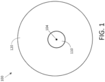
- Mode mixing optical fiber 100 has an input end 102 and an output end 103.
- Mode mixing optical fiber 100 also has a centerline 104 (defined as the point at the geometrical center of the cross-section of an optical fiber), and a refractive index profile (defined as the refractive index as a function of position of the cross-section of an optical fiber).
- the mode mixing optical fiber 100 includes an innermost core 110 (which has its own refractive index profile, defined as the refractive index as a function of position of the cross-section of the innermost core of an optical fiber); and a cladding 120 disposed about the innermost core.
- the mode mixing optical fiber is configured to deliver optical radiation having a wavelength (i.e., from its input end to its output end).
- the mode mixing optical fiber has at least five modes (i.e., modes substantially confined by the innermost core) at the wavelength.
- the mode mixing optical fiber has at least seven modes at the wavelength, or at least ten modes at the wavelength.
- the mode mixing optical fiber has at least twenty, at least thirty, at least forty or even at least fifty modes at the wavelength.
- the mode mixing optical fiber is configured to distribute a fraction of the light input at its input end (and propagating toward its output end) from its lower-order modes to its higher-order modes.
- a beam can be output from the output end of the mode mixing optical fiber that has, for example, a desired BPP and/or beam shape, such as a substantially "flat-top" profile.
- the present disclosure identifies a number of ways to configure a mode mixing optical fiber such that it distributes a fraction of the light input at its input end from its lower-order modes to its higher-order modes.
- the innermost core of the mode mixing optical fiber has a centerline (i.e., defined as described above, but with reference to the innermost core as opposed to the overall fiber) that is positioned substantially non-collinearly with the centerline of the optical fiber.
- the innermost core of the mode mixing optical fiber is disposed off-center with respect to the overall mode mixing optical fiber.
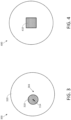
- Figure 3 is a cross-sectional schematic view of a mode mixing fiber 300, which has an innermost core 310 and a cladding 320 disposed around the innermost core.
- innermost core 310 has a centerline 314 that is disposed substantially off-center with respect to the overall fiber 300.
- the center of the innermost core 310 is laterally offset from the centerline 304 of the overall fiber 300.
- the lateral offset of the center of the innermost core with respect to the centerline of the fiber is at least 5 microns, for example, at least 10 microns, at least 20 microns, or at least 30 microns.
- the mode mixing optical fiber has a step index profile; the person of ordinary skill in the art will appreciate that other index profiles may be used.
- the innermost core of the mode mixing optical fiber can take a variety of shapes.
- the innermost core has a substantially circular cross-sectional shape.
- the mode mixing optical fiber has an innermost core that is substantially circular in cross-sectional shape, it desirably includes some other feature or characteristic that can provide for the desired distribution of radiation among modes.
- it can have a laterally-offset innermost core, as described above.
- the innermost core can have a refractive index profile configured to distribute radiation among modes, as described in more detail below.
- the innermost core of the mode mixing optical fiber has a substantially non-circular cross-sectional shape.
- mode mixing optical fiber 400 shown in cross-sectional schematic view in Figure 4 , has an innermost core 410 that has a substantially rectangular shape (here, a square).
- the substantially non-circular innermost core is centered along the centerline of the mode mixing optical fiber (i.e., the innermost core has a centerline that is positioned substantially collinear with the centerline of the optical fiber).
- the substantially-non circular innermost core is laterally offset from the centerline of the optical fiber, e.g., in any manner as described above with respect to Figure 3 .
- the innermost core can have a polygonal shape (e.g., a regular polygon or an irregular polygon), with any desirable number of sides (e.g., triangular, rectangular, pentagonal, hexagonal, octagonal).
- the vertices of the polygon can be sharp or somewhat rounded.
- a substantially non-circular innermost core need not be polygonal; it can have a rounded but non-circular shape (e.g., oval, elliptical, semicircular, etc.).
- the innermost core of the mode mixing optical fiber has one or more substantially up-doped regions and/or one or more substantially down-doped regions, configured to provide the desired distribution of radiation among its propagating modes.
- the one or more substantially up-doped regions and/or one or more substantially down-doped regions can be configured in a number of ways.
- An up-doped region is a region that has a higher refractive index at the wavelength than the remainder of the innermost core. The person of ordinary skill in the art will appreciate that this can be due to the up-doped region having more of a high refractive index dopant, or less of a low refractive index dopant than the remainder of the innermost core.
- a down-doped region is a region that has a lower refractive index at the wavelength than the remainder of the innermost core.
- the person of ordinary skill in the art will appreciate that this can be due to the down-doped region having less of a high refractive index dopant, or more of a high refractive index dopant than the remainder of the innermost core.
- an up-doped or down-doped region need include any dopant at all, e.g., it can be substantially pure silica, in cases in which the remainder of the innermost material has a different refractive index difference.
- the innermost core of the optical fiber includes one or more substantially down-doped regions disposed symmetrically around its centerline.
- the innermost core of the mode mixing optical fiber can include a substantially down-doped region having a centerline disposed substantially collinear with the centerline of the innermost core.
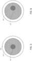
- Mode mixing optical fiber 500 has an innermost core 510 surrounded by a cladding 520.
- Innermost core 510 includes a substantially down-doped region 515, which has a centerline disposed along the centerline of the innermost core itself.
- the innermost core of the mode mixing optical fiber includes one or more substantially down-doped regions that are disposed asymmetrically around the centerline of the innermost core.
- Such substantially down-doped regions may be provided, for example, in combination with a down-doped region provided along the centerline of the innermost core as described above, or may be provided in the absence of a down-doped region provided along the centerline of the innermost core.
- optical fiber 600 shown in cross-sectional schematic view in Figure 6 , has a innermost core 610 that includes a substantially down-doped region 615 disposed offset from the centerline of the innermost core of the optical fiber (in this embodiment, also disposed offset from the centerline of the optical fiber itself).
- Figure 7 is a cross-sectional schematic view of a mode mixing optical fiber.
- the mode mixing optical fiber 700 includes an innermost core 710, which includes a down-doped ring-shaped region 715; here, too, the down-doped region is disposed with its center offset from the center of the innermost core (and also the centerline of the fiber).
- FIG 8 is a cross-sectional schematic view of yet another embodiment of a mode mixing optical fiber as described herein.
- mode mixing optical fiber 800 includes an innermost core 810, which includes down-doped regions 815a, 815b, 815c and 815d.
- the down-doped regions 815a, 815b, 815c and 815d are disposed with their centers at various distances away from the centerline 804 of the optical fiber.
- multiple down-doped regions may be disposed randomly, or alternatively, arranged in a regular geometrical arrangement (i.e., without forming a bandgap structure).
- the innermost core of a mode mixing optical fiber includes one or more substantially up-doped regions.
- the one or more substantially up-doped regions are disposed asymmetrically around the centerline of the innermost core, e.g., in any of the manners described above with respect to the down-doped regions.
- an up-doped region is disposed symmetrically around the center of the innermost core (e.g., as a ring-shaped region), but substantially towards the periphery of the innermost core (e.g., with at least 1/2, 2/3 or even 3/4 of the area of the up-doped area disposed at least half the radius of the innermost core away from the centerline of the innermost core).
- the one or more high-index regions can be provided in combination with one or more low-index regions as described above.
- substantially up-doped/down-doped regions can be provided in the innermost core of the optical fiber.
- up-doped/down-doped regions e.g., to be no more than 12, no more than 8, no more than 5, no more than 4, or even no more than 3.
- the number of up-doped/down-doped regions e.g., to be no more than 12, no more than 8, no more than 5, no more than 4, or even no more than 3.
- the innermost core of the mode mixing optical fiber can be formed in a variety of sizes.
- the innermost core of the optical fiber has a diameter (i.e., the radially-averaged distance across the innermost core) in the range of about 50 ⁇ m to about 3000 ⁇ m, e.g., in the range of about 50 ⁇ m to about 2000 ⁇ m, or about 50 ⁇ m to about 1000 ⁇ m, or about 50 ⁇ m to about 600 ⁇ m, or about 100 ⁇ m to about 3000 ⁇ m, or about 100 ⁇ m to about 2000 ⁇ m, or about 100 ⁇ m to about 1000 ⁇ m, or about 100 ⁇ m to about 600 ⁇ m, or about 200 ⁇ m to about 3000 ⁇ m, or about 200 ⁇ m to about 2000 ⁇ m, or about 200 ⁇ m to about 1000 ⁇ m, or about 200 ⁇ m to about 600 ⁇ m.
- the person of ordinary skill in the art will select an innermost core diameter to provide a desired number of modes and
- the mode mixing optical fiber may be formed in a variety of sizes.
- the mode mixing optical has an outer diameter in the range of about 100 ⁇ m to about 3600 ⁇ m, e.g., in the range of about 100 ⁇ m to about 3000 ⁇ m, or about 100 ⁇ m to about 2500 ⁇ m, or about 100 ⁇ m to about 1500 ⁇ m, or about 100 ⁇ m to about 1000 ⁇ m, or about 100 ⁇ m to about 800 ⁇ m, or about 100 ⁇ m to about 600 ⁇ m, or about 200 ⁇ m to about 3600 ⁇ m , or about 200 ⁇ m to about 3000 ⁇ m, or about 200 ⁇ m to about 2500 ⁇ m, or about 200 ⁇ m to about 1500 ⁇ m, or about 200 ⁇ m to about 1000 ⁇ m, or about 200 ⁇ m to about 800 ⁇ m, or about 200 ⁇ m to about 600 ⁇ m.
- the outer diameter of the mode mixing optical fiber is at least about 1.05 times the outer diameter of the innermost core, for example, in the range of about 1.05 to about 5 times, or about 1.05 to about 3 times, or about 1.05 to about 2 times the outer diameter of the innermost core of the mode mixing optical fiber.
- the outer diameter of the mode mixing optical fiber is at least about 1.2 times the outer diameter of the innermost core, for example, in the range of about 1.2 to about 5 times, or about 1.2 to about 3 times, or about 1.2 to about 2 times the outer diameter of the innermost core of the mode mixing optical fiber.
- the various up-doped and down-doped regions may be provided in a variety of shapes and a variety of sizes.
- the various up-doped and/or down-doped regions have a solid cross-sectional shape selected from circular, non-circular but rounded (e.g., oval, ellipse, hemicircular), polygonal (e.g., triangular, hexagonal, square).
- the various up-doped and/or down-doped regions can also be provided as annular shapes (e.g., circular rings, annular non-circular but rounded shapes, or annular polygons).
- the various up-doped and/or down-doped regions can be, for example, at least about the size of the wavelength (i.e., in radially-averaged cross-sectional width).
- the various up-doped and/or down-doped regions are, for example in the range of about 1 ⁇ m to about 2000 ⁇ m in size, e.g., in the range of about 1 ⁇ m to about 1500 ⁇ m , or about 1 ⁇ m to about 1000 ⁇ m, or about 1 ⁇ m to about 800 ⁇ m , or about 1 ⁇ m to about 600 ⁇ m, or about 1 ⁇ m to about 400 ⁇ m , or about 1 ⁇ m to about 200 ⁇ m , or about 2 ⁇ m to about 2000 ⁇ m, or about 2 ⁇ m to about 1500 ⁇ m , or about 2 ⁇ m to about 1000 ⁇ m, or about 2 ⁇ m to about 800 ⁇ m , or about 2 ⁇ m to about 600 ⁇ m, or about 2 ⁇ m to
- the total percentage of innermost core area of the up- and/or down-doped regions is in the range of about 5% to about 95%, e.g., in the range of about 5% to about 85%, or about 5% to about 75%, or about 5% to about 50%, or about 5% to about 25%, or about 10% to about 95%, or about 10% to about 85%, or about 10% to about 75%, or about 10% to about 50%, or about 10% to about 25%, or about 1% to about 10%, or about 1% to about 20%, or about 1% to about 25%.
- the one or more substantially up-doped and/or down-doped regions have a refractive index that is substantially different from that of the remainder of the innermost core.
- the substantially-up doped regions can have a refractive index (i.e., at the wavelength) that is at least about 0.001, at least about 0.002, at least about 0.003, or even at least about 0.005 greater than that of the remainder of the innermost core, e.g., at least about 0.01 or at least about 0.02 greater than that of the remainder of the innermost core.
- the substantially down-doped regions can have a refractive index that is at least about 0.001, at least about 0.002, at least about 0.003, or even at least about 0.005 less than that of the remainder of the innermost core, e.g., at least about 0.01 or at least about 0.02 less than that of the remainder of the innermost core.
- the absolute refractive index difference i.e., at the wavelength
- the absolute refractive index difference is at most about 0.2, at most about 0.1, or at most about 0.05.
- the substantially up-doped and/or down-doped regions are formed as regions of index discontinuity within the innermost core (i.e., with the change in refractive index occurring within about 1 ⁇ m in linear distance along the cross-section of the innermost core).
- the innermost core of the mode mixing optical fiber includes a single annular shaped down-doped region, e.g., in the shape of a circular ring.
- the annular shaped down-doped region can, for example, have an inner diameter in the range of 5 microns to 20 microns, and an annular thickness in the range of 0.5 microns to 3 microns.
- the refractive index of the down-doped region can be such that the relative numerical aperture value with respect to the remainder of the innermost core is, for example, in the range of 0.01 to 0.15, e.g., 0.01 to 0.10, 0.01 to 0.05, 0.02 to 0.10, or 0.02 to 0.05.
- the "diameter" of a non-circular feature is twice the radially-averaged distance from the geometrical center of the feature.
- the mode mixing optical fiber can be provided in a variety of lengths.
- the person of ordinary skill in the art can select a length sufficient to provide the desired distribution of radiation into higher order modes.
- the mode mixing optical fiber has a length in the range of about 1 m to about 100 m, e.g., in the range of about 1 m to about 50 m, or about 1 m to about 40 m, or about 1 m to about 50 m, or about 1m to about 20 m, or about 1 m to about 10 m, or about 1 m to about 5 m, or about 5 m to about 100 m, or about 5 m to about 100 m, e.g., in the range of about 5 m to about 50 m, or about 5 m to about 40 m, or about 5 m to about 50 m, or about 5 m to about 20 m, or about 10 m to about 100 m, or about 10 m to about 50 m, or about 10 m to about 40 m.
- the mode mixing optical fiber does not have a circularly-symmetric cross-sectional profile.
- the cross-sectional profile of the mode mixing optical fiber is formed as a helix along the length hereof.
- the various elements of the optical fiber twist in a helical configuration along the length of the fiber, for example, with a pitch in the range of about 1 mm to about 100 cm, e.g., in the range of about 1 mm to about 50 cm, or about 1 mm to about 30 cm, or about 1 mm to about 20 cm, or about 1 mm to about 10 cm, or about 1 mm to about 5 cm, or about 2 mm to about 100 cm, or about 2 mm to about 50 cm, or about 2 mm to about 30 cm, or about 2 mm to about 20 cm, or about 2 mm to about 10 cm, or about 2 mm to about 5 cm, or about 5 mm to about 100 cm, or about 5 mm to about 50 cm, or about 5 mm to about 30 cm, or about 5 mm to about 20 cm, or about 5 mm to about 10 cm, or about 5 mm to about 5 cm, or about 1 cm to about 100 cm, or about 1 cm to about 50 cm, or about 5 mm to about 30 cm, or about 5 mm
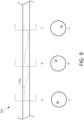
- Such a configuration is shown in schematic view in Figure 9 .
- a section of optical fiber 900 having an off-center innermost core is shown in side view, with the centerline 914 of the innermost core shown as a dashed line.
- the cross-sectional profile at each of positions A, B and C is shown.
- the off-center innermost core is formed as a helix throughout the fiber.
- the efficiency of the mode mixing process can be significantly increased by use of such a helical configuration.
- Such a fiber may be made using conventional methodologies (e.g., by spinning the preform during the draw of the optical fiber).
- the mode mixing optical fiber can be made from conventional material using conventional methods in the art.
- the optical fiber can be made using various silica-based glasses (e.g., germanosilicates, borosilicates, aluminosilicates, fluorosilicates and combinations thereof).
- the innermost core e.g., exclusive of any up-doped or down-doped regions
- the cladding at least in the region immediately surrounding the innermost core
- includes fluorine-doped silica includes fluorine-doped silica.
- the innermost core e.g., exclusive of any down-doped regions
- the cladding at least in the region immediately surrounding the innermost core
- Conventional dopants can be used to provide up-doped and down-doped regions.
- Conventional methods of making optical fibers e.g., stacking together various rods and tubes of different refractive indices, followed by collapsing them to a preform and drawing the preform) can be used to make the mode mixing optical fibers described herein.
- the person of ordinary skill in the art can provide mode mixing optical fibers providing a wide variety of beam parameter products, and thus a wide variety of divergence angles.
- the beam divergence of the mode mixing optical is in the range of about 40 mrad , 60 mrad or 80 mrad up to the numerical aperture of the optical fiber, e.g., in the range of about 40 mrad to about 600 mrad, or about 40 mrad to about 300 mrad, or about 40 mrad to about 160 mrad, or about 40 mrad to about 140 mrad, or about 40 mrad to about 120 mrad, or about 40 mrad to about 100 mrad, or about 40 mrad to about 80 mrad, or about 60 mrad to about 600 mrad, or about 60 mrad to about 300 mrad, or about 60 mrad to about 160 mrad, or about 60 mrad to about 140 mrad, or about 60 mrad to about 120 m
- the person of ordinary skill in the art can provide mode mixing optical fibers having different divergence angles for different applications.
- the person of ordinary skill in the art in some embodiments, can provide mode mixing optical fibers with a beam divergence angles as high as the NA of the innermost core.
- the person of ordinary skill in the art can provide mode mixing optical fibers providing a substantially flat-top output.
- the mode mixing optical fiber can be configured to guide or output a beam (i.e., as defined by an outer periphery at 5% of the peak intensity) having at least 70%, at least 80%, or even at least 90% of its cross-sectional area within about 20%, within about 15%, or even within about 10% of its average intensity.
- the mode mixing fiber can be configured to guide or output radiation (i.e., as defined by an outer periphery at 5% of the peak intensity) having at least 70%, at least 80%, or even at least 90% of its cross-sectional area within about 20%, within about 15%, or even within about 10% of its average intensity, e.g., when the radiation input to the mode mixing fiber has no more than 50%, no more than 40%, no more than 30% or even no more than 20% of its cross-sectional area within about 20%, within about 15%, or even within about 10% of its average intensity (e.g., with its highest intensity at the center).
- radiation i.e., as defined by an outer periphery at 5% of the peak intensity
- the mode mixing fiber can be configured to guide or output radiation (i.e., as defined by an outer periphery at 5% of the peak intensity) having at least 70%, at least 80%, or even at least 90% of its cross-sectional area within about 20%, within about 15%, or even within about 10% of its average intensity, e.
- the mode mixing optical fibers can be provided with a variety of numerical aperture values.
- the numerical aperture of a mode mixing optical fiber is in the range of about 0.10 to about 0.60, e.g., in the range of about 0.10 to about 0.40 or about 0.10 to about 0.30, or about 0.10 to about 0.22, or about 0.15 to about 0.60, or about 0.15 to about 0.40, or about 0.15 to about 0.30.
- the various regions of the refractive index profile of the innermost core can perturb the propagation of radiation therein, e.g., by acting as a scattering (or weakly guiding) center, reflecting (or guiding) the light away and populating the higher order modes of the innermost core.
- the performance of the mode mixing optical fibers described herein may be influenced by several design parameters including, for example, the lateral offset of the innermost core, the refractive index profile of the innermost core, the numerical aperture, the length of the mode mixing fiber, any coiling conditions (diameter and length), and any helicity of the refractive index profile of the innermost core.
- the design of the mode mixing optical fiber may be scaled in order to provide a desired innermost core size (e.g., to match the size of a separate beam delivery fiber when one is used.
- Optical system 1030 includes a mode mixing optical fiber 1000, having an input end 1002 and an output end 1004, as well as a first optical fiber 1040, having an output end 1044.
- the output end 1044 of the first optical fiber is directly optically coupled to the input end 1002 of the mode mixing optical fiber (i.e., without any substantial optical component therebetween).
- the output end of the first optical fiber can be fusion spliced to the input end of the mode mixing optical fiber.
- the first optical fiber can couple light radiation to the input end of the mode mixing optical fiber such that their centerlines are aligned with one another (i.e., even though the innermost core of the mode mixing optical fiber may be offset from the centerline of the mode mixing optical fiber).
- the mode mixing optical fiber can accept radiation from a single or few-moded optical fiber and, through distribution of radiation into higher order modes, provide an output beam having desired optical characteristics (e.g., as described above).
- the first optical fiber is single-mode at the wavelength.
- the first optical fiber has 7 or fewer, 6 or fewer, 5 or fewer or even 4 or fewer modes at the wavelength.
- the mode mixing fiber can accept radiation from a multimode optical fiber, or from a solid state source (e.g., via coupling through free-space optics).
- the first optical fiber is configured to provide radiation from an optical fiber laser or optical fiber amplifier.
- the first optical fiber can be an active optical fiber of a fiber laser or a fiber amplifier, e.g., a rare-earth doped fiber, or a fiber configured to provide gain through some non-linear process (e.g., Raman scattering, Brillouin scattering).
- the first optical fiber has substantially the same diameter as the mode mixing optical fiber. Such embodiments may be especially advantaged, in that the alignment of the first optical fiber to the mode mixing optical fiber (i.e., for optical coupling, for example, via fusion splicing) can be simplified. Similarly, in certain embodiments, the diameter of the innermost core of the first optical fiber is within 10%, or even within 5% of the diameter of the innermost core of the mode mixing optical fiber.
- the mode mixing optical fiber can provide a beam having desirable optical characteristics from its second end.
- the optical system is configured to launch a free space-propagating beam (e.g., as identified by reference numeral 1060 in Figure 10 ) from the second end of the mode mixing optical fiber.
- the mode mixing optical fiber can act as a beam delivery fiber, and can be configured in a beam delivery cable, e.g., ruggedized to allow for handling in an industrial environment. If necessary, additional optics (e.g., collimating lenses and/or other diffractive or refractive elements) can be provided at the output end of the mode mixing optical fiber.
- the optical system further includes a second optical fiber, the second optical fiber being a multi-mode at the wavelength, the second optical fiber having an input end and an output end, the input end of the second optical fiber being directly optically coupled to the output end of the mode mixing optical fiber.
- Optical system 1130 includes a first optical fiber 1140 and a mode mixing optical fiber 1100 with the output 1144 of the first optical fiber directly optically coupled to the input 1102 of the mode mixing optical fiber as described above.
- Optical system 1100 further includes a second optical fiber 1150, having an input end 1152 and an output end 1154, with the input end 1152 of the second optical fiber directly optically coupled (here, fusion spliced) to the output end 1104 of the mode mixing optical fiber.
- the mode mixing optical fiber can act to transform the optical characteristics of the output of the first optical fiber (e.g., intensity profile) to a more desirable state (e.g., having a flat-top intensity profile) to be coupled into the second optical fiber.
- the system can be configured to launch a free space-propagating beam (e.g., as identified by reference numeral 1160 in Figure 11 ) from the second end of the second optical fiber.
- the second optical fiber can act as a beam delivery fiber, and can be configured in a beam delivery cable, e.g., ruggedized to allow for handling in an industrial environment.
- additional optics e.g., collimating lenses and/or other diffractive or refractive elements
- an optical system includes a mode mixing optical fiber having its input end coupled to the output of an optical source, such as a solid state laser.
- the optical source can be coupled to the input end of the mode mixing fiber, for example, using free-space optics.
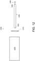
- FIG. 12 An example of such an embodiment is shown in FIG. 12 .
- Optical fiber system 1230 includes an optical source 1270 (e.g., a solid-state laser) having its output coupled to the input end 1202 of mode mixing optical fiber 1200 through free-space optics 1275 (e.g., one or more lenses).
- a free space-propagating beam (e.g., as identified by reference numeral 1260 in Figure 12 ) can be emitted from the second end 1200 of the mode mixing optical fiber.
- the diameter of the innermost core of the second optical fiber can vary depending on the end-user needs, for example, to allow for implementation in already existing systems.
- the diameter of the innermost core of the second optical fiber can be, for example, within about 10%, or even within about 5% of the diameter of the innermost core of the mode mixing optical fiber.
- the innermost core of the second optical fiber can be a different size, e.g., in the range of about 50 ⁇ m to about 3000 ⁇ m, or about 50 ⁇ m to about 2000 ⁇ m, or about 50 ⁇ m to about 1000 ⁇ m, or about 50 ⁇ m to about 600 ⁇ m, or about 100 ⁇ m to about 3000 ⁇ m, or about 100 ⁇ m to about 2000 ⁇ m, or about 100 ⁇ m to about 1000 ⁇ m, or about 100 ⁇ m to about 600 ⁇ m, or about 200 ⁇ m to about 3000 ⁇ m, or about 200 ⁇ m to about 2000 ⁇ m, or about 200 ⁇ m to about 1000 ⁇ m, or about 200 ⁇ m to about 600 ⁇ m.
- the systems described herein can be configured to output a beam (i.e., as defined by an outer periphery at 5% of the peak intensity) having at least 70%, at least 80%, or even at least 90% of its cross-sectional area within about 20%, within about 15%, or even within about 10% of its average intensity, e.g., when the radiation input to the mode mixing fiber has no more than 50%, no more than 40%, no more than 30% or even no more than 20% of its cross-sectional area within about 20%, within about 15%, or even within about 10% of its average intensity (e.g., with its highest intensity at the center).
- a beam i.e., as defined by an outer periphery at 5% of the peak intensity
- Another aspect of the disclosure is a method for providing guided radiation of the wavelength having a desired intensity profile.
- the method includes coupling input radiation into a first end of a mode mixing fiber as described herein, and guiding the radiation along the mode mixing optical fiber to provide guided radiation having a desired intensity profile, e.g., a flat-top intensity profile as described herein.
- the guided radiation i.e., as defined by an outer periphery at 5% of the peak intensity
- the guided radiation having the desired intensity profile has at least 70%, at least 80%, or even at least 90% of its cross-sectional area within about 20%, within about 15%, or even within about 10% of its average intensity.
- the radiation can be guided along a length of the mode mixing optical fiber of, for example, in the range of about 1 m to about 100 m, e.g., in the range of about 1 m to about 50 m, or about 1 m to about 40 m, or about 1 m to about 50 m, or about 1m to about 20 m, or about 1 m to about 10 m, or about 1 m to about 5 m, or about 5 m to about 100 m, or about 5 m to about 100 m, e.g., in the range of about 5 m to about 50 m, or about 5 m to about 40 m, or about 5 m to about 50 m, or about 5 m to about 20 m, or about 10 m to about 100 m, or about 10 m to about 50 m, or about 10 m to about 40 m to provide the radiation having the desired intensity profile.
- the input radiation has a substantially different intensity profile than the desired intensity profile.
- the input radiation has no more than 50%, no more than 40%, no more than 30% or even no more than 20% of its cross-sectional area within about 20%, within about 15%, or even within about 10% of its average intensity (e.g., with its highest intensity at the center).
- the method can be used in conjunction with any of the mode mixing fibers or systems as described herein.
- Another aspect of the disclosure is a method for providing a free space-propagating optical beam using an optical system as described herein.
- the method includes propagating radiation of the wavelength from the first optical fiber into the mode mixing optical fiber; and propagating the radiation from the output end of the mode mixing optical fiber. If the system includes a second optical fiber as described above, the method can further include propagating the radiation through the second optical fiber and from its output end.
- the method can be performed such that the divergence, BPP and/or flatness is as described in any embodiment above.
- the beam (i.e., as defined by an outer periphery at 5% of the peak intensity) having the desired intensity profile has at least 70%, at least 80%, or even at least 90% of its cross-sectional area within about 20%, within about 15%, or even within about 10% of its average intensity.
- the input radiation has a substantially different intensity profile than the desired intensity profile.
- the input radiation has no more than 50%, no more than 40%, no more than 30% or even no more than 20% of its cross-sectional area within about 20%, within about 15%, or even within about 10% of its average intensity (e.g., with its highest intensity at the center).
- Example 1 the overall test configuration was as shown in Figure 11 , with the mode mixing fiber configured to transform radiation output from a large mode area single mode fiber to a beam delivery cable.
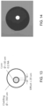
- the mode mixing optical fiber is shown in schematic view in Figure 13 , with the cleaved fiber endface shown in the photograph of Figure 14 .
- the mode mixing optical fiber has a germanium-coped core 60 ⁇ m in diameter, with a step index profile.
- the core has a numerical aperture of 0.11, and is laterally offset with respect to the centerline of the overall optical fiber by 20 ⁇ m.
- the overall fiber diameter is 360 ⁇ m.
- the first optical fiber is a conventional large mode area single mode fiber having a 20 ⁇ m diameter core, numerical aperture of 0.06, and overall diameter of 400 ⁇ m.
- the second optical fiber i.e., of the beam delivery cable
- the second optical fiber is matched to certain commercially available devices, and has a 100 ⁇ m diameter core, a numerical aperture of 0.22, an overall fiber diameter of 360 ⁇ m and a length of 25 m.
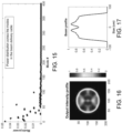
- FIGs 15-17 The results of calculations are shown in Figures 15-17 .
- the power distribution among the modes excited in the beam delivery cable is shown in Figure 15 .
- the total output intensity delivered by the beam delivery cable is shown in Figure 16 , and the corresponding beam profile is shown in Figure 17 .
- the output beam is flat-top shaped and the BPP is estimated to be about 3.4 mm ⁇ mrad.
- the system was configured with the mode mixing optical fiber as a beam delivery fiber (e.g., as shown in Figure 11 ).
- the mode mixing optical fiber has a silica core 100 ⁇ m in diameter, surrounded by a down-doped fluorine cladding layer sufficient to provide a numerical aperture of 0.22, with a silica outer cladding to provide an overall fiber diameter of 360 ⁇ m.
- the core includes a low-index ring formed by fluorine-doped silica.
- the ring is 4 ⁇ m in annular thickness, having an inner diameter of 30 ⁇ m with its center laterally offset from the centerline of the optical fiber by 12 ⁇ m.
- the index contrast between the ring and the remainder of the innermost core is sufficient to provide a numerical aperture value of 0.1 (i.e., between the material of the ring and that of the rest of the innermost core; the ring itself is not sufficient to guide light of the wavelength).
- the design is shown in schematic cross-sectional view in Figure 23 .
- the first optical fiber is a conventional large mode area single mode fiber as described above in Example 1. Calculation results are summarized in Figures 25-27 , in which the power distribution among the modes excited in the mode mixing optical fiber is shown in Figure 25 ; the total output intensity delivered by the second end of the mode mixing optical fiber is shown in Figure 26 ; and the corresponding beam profile is shown in Figure 27 .
- the mode mixing fiber is configured as a beam delivery cable.
- the mode up-conversion is demonstrated on the plot showing the power distribution in Figure 25 (only the first 100 modes were plotted for clarity purposes).
- the BPP was estimated around 4 mm ⁇ mrad.
- the output beam is not calculated to be exactly flat-top shaped (although it is remarkably flat as compared to a Gaussian beam). This can be changed by the person of ordinary skill in the art by modifying appropriately the design of the fiber, the size and location of the core elements.
- FIG. 28-30 An experimental demonstration of the mode mixing created by the up-conversion beam delivery cable using the mode mixing fiber of Figures 23 and 24 is shown in Figures 28-30 .
- the measurement setup is shown in schematic view in Figure 28 .
- the measured intensity and beam profile displayed respectively in Figures 29 and 30 demonstrate good uniformity with a BPP measured at 3.9 mm ⁇ mrad, demonstrating the mode up-conversion occurring in this fiber used as beam delivery cable.
- This can be compared to the results shown in Figure 21 , which resulted from the use of a conventional beam delivery cable.
- the low-index ring does appear in the output intensity profile with a 50 % intensity contrast compared to the maximum intensity. This ring contrast can be reduced by modifying appropriately the fiber design, as shown below with respect to Example 3.
- the system was configured substantially similarly to the configuration of Example 2, but with the numerical aperture value of the low-index ring in the core being 0.02 (i.e., instead of 0.1 as in Example 2).
- FIG. 31 and 32 An experimental demonstration of the mode mixing created by the up-conversion beam delivery cable using the mode mixing fiber of this Example is shown in Figures 31 and 32 .
- the measured intensity and beam profile displayed respectively in Figures 31 and 32 demonstrate good uniformity. This can be compared to the results Example 2, demonstrating that in fact appropriate design can maintain a desirably flat-top profile while reducing the intensity contrast caused by the down-doped ring.
- mode mixing optical fibers of different core diameters were used, one of 50 ⁇ m core and another of 25 ⁇ m core diameter, with single mode input radiation.
- a first experiment using a 50 ⁇ m core mode mixing fiber is described with respect to Figure 33 .
- an LMA/GDF 20/400 fiber was spliced to the input end of a 25 m long mode mixing optical fiber having a down-doped ring disposed offset within the inner core; details are shown in Figure 33 .
- Single mode radiation at wavelength 1.06 ⁇ m was coupled from the LMA-GDF 20/400 fiber into the mode mixing optical fiber. The intensity was measured at cleaved endface at the output of the mode mixing optical fiber.
- the output intensity was substantially uniform, but for some intensity contrast at the position of the ring-shaped down-doped element.
- the BPP was about 1.3 mm-mrad.
- the mode mixing optical fiber was similar to that of the first experiment above, but with a 25 ⁇ m core diameter; dimensions are provided in Figure 33 .
- the mode mixing fiber was 5 m long and was coiled with an 8 mm coil diameter.
- the input fiber was a single mode SMF-28 fiber, and the radiation was of wavelength 1.55 m.
- Single mode radiation was coupled from the LMA-GDF 20/400 fiber into the mode mixing optical fiber.
- the output intensity was substantially uniform.
- the BPP was about 1.5 mm-mrad.
- This example demonstrates the desirable increase in beam divergence for a mode mixing optical fiber having a helical profile.
- Two mode mixing optical fibers were made, identical but for the fact that for the "spun" fiber, the preform was spun during drawing to provide a helical profile with a period of 50 revolutions/m.
- Beam divergence was measured as a function of fiber length using a cutback methodology. Results are shown in the graph of Figure 35 . Notably, beam divergence was substantially increased for the spun fiber.
- various multimode fibers were spliced to a mode mixing fiber as described herein.
- the mode mixing fiber was 25 m long, and was otherwise similar to the mode mixing fiber of Example 3, but for the NA value of the down-doped ring being 0.05.
- the 2D beam intensities of the input multimode fiber and the output of the mode mixing fiber are provided in Figure 36 , and demonstrate that relatively inhomogeneous intensities in the input multimode fiber were converted to relatively flat-top intensities by the mode mixing fibers.
- the graph of Figure 36 demonstrates that there is relatively little impact on beam brightness.
Landscapes
- Physics & Mathematics (AREA)
- Optics & Photonics (AREA)
- Electromagnetism (AREA)
- General Physics & Mathematics (AREA)
- Engineering & Computer Science (AREA)
- Plasma & Fusion (AREA)
- Lasers (AREA)
- Optical Couplings Of Light Guides (AREA)
- Optical Fibers, Optical Fiber Cores, And Optical Fiber Bundles (AREA)
Description
- This application claims the benefit of priority of
U.S. Provisional Patent Application no. 62/204,900, filed August 13, 2015 - The present disclosure relates generally to optical fibers and optical fiber lasers. The present disclosure relates more particularly to mode mixing optical fibers useful, for example in providing optical fiber laser outputs having a desired beam product parameter and beam profile.
- High power optical lasers and amplifiers are widely used in a variety of industries for a variety of purposes, such as laser cutting, welding and machining of various materials. Research and development in rare-earth doped optical fibers along with the discovery of specialty fiber designs such as Large-Mode Area (LMA) fibers has triggered the introduction of a variety of high power fiber laser and amplifier modules. Multi-kW fiber lasers and amplifiers have been realized with very high efficiencies and are fueling the growth of laser material processing. Of course, other types of high power lasers, such as solid-state lasers, are also commonly used in materials processing applications.
- Lasers and amplifiers used in the field of materials processing desirably fulfill specific requirements in terms of output power and beam profile. In terms of power, the laser or amplifier system desirably delivers radiation with a wavelength and an energy that is high enough to process a desired material, typically on the order of kilowatts. Two sorts of kW-level fiber lasers can be distinguished: multi-mode and single-mode. Single-mode fiber lasers typically deliver on the order of 1-3 kW of optical power, while multi-mode fiber lasers typically operate in the range of several tens of kW of output power. For material processing applications, both single mode and multi-mode fiber lasers are used. A multi-mode laser can be configured, for example, by using a multi-mode active fiber, or by combining the outputs of several single mode fiber lasers into a multi-mode delivery fiber for delivery to a workpiece. Similarly, a multi-mode delivery fiber is often used to deliver power from a solid-state laser to a workpiece.
- In terms of beam profile, users typically desire the delivered beam to have a desired Beam Parameter Product (BPP). As used herein, the BPP is defined as the product of the beam radius R and the divergence angle of the beam θ, expressed in units of mm-mrad. The beam radius R in mm is defined as half of the Beam Diameter measured at 13.5% of the maximum intensity as the beam emerges from the optical fiber. The divergence angle θ in mrad is defined as the half-angle formed with the optical axis as the beam propagates from the end of a beam delivery optical fiber. While desired BPP values will vary from application to application, three typical ranges of BPP values for fiber-coupled lasers are provided below:
- 1.5 to 2 mm·mrad for a 50 µm core diameter beam delivery cable
- 3 to 4 mm·mrad for a 100 µm core diameter beam delivery cable
- 6 to 8 mm·mrad for a 200 µm core diameter beam delivery cable
- Moreover, in many applications, the delivered beam has an intensity profile that is substantially evenly distributed along the beam. Such a "flat-top" profile is different from a Gaussian profile, in which the maximum intensity is only at the center with a relatively sharp drop-off in intensity away from the center. A "flat-top" profile can help to enable controlled and accurate cutting, welding or machining process.
- In many applications, a beam with a substantially circular profile is also (or alternatively) desired.
- In order to use such lasers for material processing applications while satisfying the required beam parameter product (BPP), conventional optical fiber laser and amplifier systems have a single mode or multi-mode laser or amplifier output coupled into a beam delivery cable for transmission of the output to a workpiece. Similarly, conventional solid-state lasers are coupled to a beam delivery cable for transmission of the laser output to a workpiece. Commonly used beam delivery cables are made with highly multi-mode step-index fibers with typical core diameters of 50, 100, 200, 400 and 600 microns and numerical apertures (NA) varying from 0.1 to 0.4 (and often greater than 0.4). A number of techniques have been attempted to provide both a desired BPP and a desired flat-top profile, such as offset splicing between a single mode laser output (launch fiber) and the beam delivery cable, beam delivery optical fibers with shaped cores, external beam shaping techniques, mechanical fiber micro-bending, fiber tapers (adiabatic and/or abrupt), long period gratings and multimode interference in multi-mode fibers. However, each of these suffers from a number of drawbacks.
- Kevin Farley et al, "Optical fiber designs for beam shaping ", Proc. SPIE 8961, Fiber Lasers XI: Technology, Systems, and Applications, 89612U (12 March 2014), doi:10.1117/12.2041992 discusses optical fiber designs that shape the output beam profile, including the ability to transform Gaussian beams to shapes required for industrial applications. The authors report on how different waveguide structures perform in the near field and show results on how to achieve a flat-top shape with circular outputs.
- Accordingly, there remains a need for improved optical fibers, systems and methods that can, for example, provide one or more of a desired BPP value, a desired intensity profile (e.g., a "flat top" intensity profile), and a circular beam shape.
-
US4372645A describes optical fibers having enhanced mode coupling produced by an asymmetric refractive index profile that varies periodically along the length of the fiber. The prescribed variations are obtained by means of a fabrication process that includes periodically varying the source of at least one of the fiber materials in a direction transverse to the fiber-drawing direction. This transverse periodicity is translated into the desired longitudinal periodicity along the fiber by the fiber-drawing process. - The invention provides a mode mixing optical fiber according to
independent claim 1 and a method for providing a free space-propagating optical beam according to independent claim 14. Further embodiments are provided by the dependent claims. - These as well as other aspects, embodiments, advantages, and alternatives, will become apparent to those of ordinary skill in the art by reading the following detailed description, with reference where appropriate to the accompanying figures. Various embodiments of the optical fibers, systems and methods described herein can be useful in laser machining applications as well as in a variety of additional applications that would benefit from, for example, fiber beam control techniques.
- The embodiments shown in
figures 1-5 ,13-22 are not encompassed by the wording of the claims but are considered as useful for understanding the invention. -
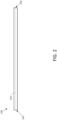
Figure 1 is a cross-sectional schematic view andFigure 2 is a schematic side view of a mode mixing optical fiber according to one embodiment of the disclosure. -
Figure 3 is a cross-sectional schematic view of a mode mixing optical fiber according to another embodiment of the disclosure. -
Figure 4 is a cross-sectional schematic view of a mode mixing optical fiber according to another embodiment of the disclosure. -
Figure 5 is a cross-sectional schematic view of a mode mixing optical fiber according to another embodiment of the disclosure. -
Figure 6 is a cross-sectional schematic view of a mode mixing optical fiber according to another embodiment of the disclosure. -
Figure 7 is a cross-sectional schematic view of a mode mixing optical fiber according to another embodiment of the disclosure. -
Figure 8 is a cross-sectional schematic view of a mode mixing optical fiber according to another embodiment of the disclosure. -
Figure 9 is a schematic side view of a mode mixing optical fiber according to another embodiment of the disclosure. -
Figure 10 is a schematic view of an optical system according to one embodiment of the disclosure. -
Figure 11 is a schematic view of an optical system according to another embodiment of the disclosure. -
Figure 12 is a schematic view of an optical system according to another embodiment of the disclosure. -
Figure 13 is a schematic cross-sectional view of the mode mixing optical fiber used in the experiments of Example 1. -
Figure 14 is a picture of a cleaved fiber endface of the mode mixing optical fiber used in the experiments of Example 1. -
Figure 15 is a graph showing the calculated power distribution among modes excited in the mode mixing beam delivery cable in the experiments of Example 1. -
Figure 16 is a 2D plot of the calculated total output intensity delivered by the mode mixing beam delivery cable in the experiments of Example 1. -
Figure 17 is a plot of the calculated profile of the beam delivered by the mode mixing beam delivery cable in the experiments of Example 1. -
Figure 18 is a graph showing the calculated power distribution among modes excited in a conventional beam delivery cable in the experiments of Example 1. -
Figure 19 is a 2D plot of the calculated total output intensity delivered by a conventional beam delivery cable in the experiments of Example 1. -
Figure 20 is a plot of the calculated profile of the beam delivered by a conventional beam delivery cable in the experiments of Example 1. -
Figure 21 is a schematic view of a conventional system and a 2D graph of the total output intensity delivered thereby as described in the experiments of Example 1. -
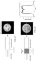
Figure 22 is a schematic view of an optical system including an offset core mode mixing fiber and a 2D graph of the total output intensity delivered thereby as described in the experiments of Example 1. -
Figure 23 is a cross-sectional schematic view of the design of the mode-mixing optical fiber used in the experiments of Example 2. -
Figure 24 is an index-contrast image of a cleaved endface of the fiber ofFigure 22 . -
Figure 25 is a graph showing the calculated power distribution among modes excited in the mode mixing beam delivery cable in the experiments of Example 2. -
Figure 26 is a 2D plot of the calculated total output intensity delivered by the mode mixing beam delivery cable in the experiments of Example 2. -
Figure 27 is a plot of the calculated profile of the beam delivered by the mode mixing beam delivery cable in the experiments of Example 2. -
Figure 28 is a schematic view of an optical system including an offset low-index ring mode mixing fiber used in the experiments of Example 2. -
Figure 29 is a 2D graph of the total output intensity delivered by the system ofFigure 27 as described in the experiments of Example 2. -
Figure 30 is an intensity profile of the output delivered by the system ofFigure 27 as described in the experiments of Example 2. -
Figure 31 is a 2D graph of the total output intensity delivered in the experiments of Example 3. -
Figure 32 is an intensity profile of the output delivered in the experiments of Example 3. -
Figure 33 is a set of images providing the results of a first experiment described in Example 4. -
Figure 34 is a set of images providing the results of a second experiment described in Example 4. -
Figure 35 is a plot of beam divergence vs. fiber length for the mode mixing fibers described in Example 5 -
Figure 36 is a set of images providing the results of the experiments described in Example 6. - As the person of skill in the art will appreciate, the drawings are not necessarily drawn to scale, and various elements of the system may in certain drawings be omitted for purposes of clarity.
- In the following discussion it is assumed that the reader has the basic knowledge of the structure of optical fibers familiar to the person of skill in the art. Thus, the concepts of a fiber core, cladding, and coating are not discussed in detail. As is familiar to the person of skill in the art, radiation having a wavelength propagates generally in the core of the fiber, the diameter of which is typically in the range of a few microns to a several hundred microns, even in some embodiments up to 1500 microns. The refractive index difference between the core and the cladding acts to confine the light in one or more propagating modes, generally in the core of the fiber (although the person of ordinary skill in the art will appreciate that some energy is actually present in the cladding in the region near the core).
- The terms "light" or "optical", as used herein, are used broadly as understood by one of ordinary skill in the art of optical waveguides, and are not to be limited as pertaining only to the visible range of wavelengths. Refractive indices described herein are described with reference to the wavelength of the radiation. In certain embodiments of the optical fibers, systems and methods described herein, the wavelength is in the visible or near-infrared (e.g., in the range of about 0.5 µm to about 3 µm).
- The inventors have noted that in a multi-mode beam delivery fiber, if the light is uniformly distributed among all available modes (i.e., all available transverse modes), the output beam can exhibit a relatively flat-top intensity profile. Populating higher-order modes also affects the divergence angle of the output beam (since higher-order modes propagate at larger divergence angles) and increases the BPP. When all modes are evenly populated, the beam divergence equals the fiber core numerical aperture.
- However, in conventional systems, all modes are not evenly populated. Rather, the number of modes excited in a multi-mode beam delivery fiber and the relative amount of power coupled in each mode is determined by, e.g., the spatial overlap between the incident laser radiation (e.g., from an active fiber) and the modes of the core of the beam delivery fiber. Since transverse modes are orthogonal, only the modes with a non-zero spatial overlap with the input laser beam (e.g., from an active fiber) can be populated. The relative amount of power carried by each mode is determined by the fraction of spatial overlap. As a result, the beam profile and the BPP available at the output of the beam delivery will vary based on the particular type of laser or amplifier being used (i.e., depending on the profile of the laser/amplifier output). For example, when using a single mode laser or amplifier source, the significant difference in size and form factor with the multi-mode step index fiber in a conventional beam delivery cables results in a low level of mode mixing (i.e., only a few lower order modes are typically populated). Use of a multi-mode laser or amplifier fiber can help matters somewhat, but due to the fact that such multi-mode laser or amplifier fibers are typically only few-moded, the beam delivery fiber still typically propagates radiation in only its lower order modes. When only lower order modes are populated, the delivered beam is typically much higher in intensity at its center than at its periphery. When coupling a solid-state laser to a beam delivery fiber, for example, through free-space optics, the beam delivery fiber can similarly transmit radiation chiefly in its lower order modes, similarly leading to a delivered beam having a more intense center.
- The present inventors have addressed the drawbacks in the prior art by providing optical fibers configured to, for example, couple laser/amplifier radiation (e.g., from single-moded or few-moded fiber, or coupled from a solid-state laser) input at its input end (and propagating toward its output end) into its higher order modes. Such an optical fiber, when used as a mode transformation fiber or a beam delivery fiber in an optical fiber laser or amplifier system can provide an output having one or more of a desired BPP value, a desired intensity profile (e.g., a "flat top" intensity profile), and a circular beam shape. In certain embodiments, according to the claimed invention, such mode mixing optical fibers are provided by introducing asymmetry within the core in order to perturb the mode overlap between an input optical fiber and the mode mixing optical fiber, thereby increasing mode mixing.
- As the person of ordinary skill in the art will appreciate, the optical fiber designs described herein are scalable, and offer many degrees of freedom to fulfill the needs of the end-user in terms of BPP while maintaining a desired intensity profile (e.g., a "flat top" and/or circular beam). Based on the present disclosure, the person of ordinary skill in the art can use conventional optical simulation techniques to provide additional designs within the scope of the disclosure.
- Advantageously, such systems can be provided in an all-fiber monolithic configuration using standard fusion splicing procedures and conventional commercial splicing equipment. Such an all-fiber approach can offer easy and simple handling, implementation and maintenance. As the person of ordinary skill in the art will appreciate, the optical fibers, methods and systems described herein do not require external elements, spatial filtering or special treatment to be operated and to perform mode up-conversion. The optical fibers described herein can be packaged into beam delivery cables and simply spliced to the output of the laser, and thus are compatible with existing optical fiber laser and amplifier systems. Similarly, the optical fibers described herein can be coupled, for example through free-space optics, to the output of other types of lasers, such as solid-state lasers.
- An embodiment of the disclosure is shown in cross-sectional schematic view in
Figure 1 , and in schematic side view inFigure 2 . Mode mixingoptical fiber 100 has aninput end 102 and anoutput end 103. Mode mixingoptical fiber 100 also has a centerline 104 (defined as the point at the geometrical center of the cross-section of an optical fiber), and a refractive index profile (defined as the refractive index as a function of position of the cross-section of an optical fiber). The mode mixingoptical fiber 100 includes an innermost core 110 (which has its own refractive index profile, defined as the refractive index as a function of position of the cross-section of the innermost core of an optical fiber); and acladding 120 disposed about the innermost core. The mode mixing optical fiber is configured to deliver optical radiation having a wavelength (i.e., from its input end to its output end). Notably, the mode mixing optical fiber has at least five modes (i.e., modes substantially confined by the innermost core) at the wavelength. For example, in certain embodiments, the mode mixing optical fiber has at least seven modes at the wavelength, or at least ten modes at the wavelength. In other embodiments, the mode mixing optical fiber has at least twenty, at least thirty, at least forty or even at least fifty modes at the wavelength. - Critically, the mode mixing optical fiber is configured to distribute a fraction of the light input at its input end (and propagating toward its output end) from its lower-order modes to its higher-order modes. Through the distribution of optical power among not only the low-order modes but also the higher-order modes of the mode mixing optical fiber, a beam can be output from the output end of the mode mixing optical fiber that has, for example, a desired BPP and/or beam shape, such as a substantially "flat-top" profile. The present disclosure identifies a number of ways to configure a mode mixing optical fiber such that it distributes a fraction of the light input at its input end from its lower-order modes to its higher-order modes. For example, in certain embodiments of the disclosure, the innermost core of the mode mixing optical fiber has a centerline (i.e., defined as described above, but with reference to the innermost core as opposed to the overall fiber) that is positioned substantially non-collinearly with the centerline of the optical fiber. In other words, in certain embodiments, the innermost core of the mode mixing optical fiber is disposed off-center with respect to the overall mode mixing optical fiber.
Figure 3 is a cross-sectional schematic view of amode mixing fiber 300, which has aninnermost core 310 and acladding 320 disposed around the innermost core. In this embodiment,innermost core 310 has acenterline 314 that is disposed substantially off-center with respect to theoverall fiber 300. That is, the center of theinnermost core 310 is laterally offset from thecenterline 304 of theoverall fiber 300. The lateral offset of the center of the innermost core with respect to the centerline of the fiber is at least 5 microns, for example, at least 10 microns, at least 20 microns, or at least 30 microns. In this embodiment, the mode mixing optical fiber has a step index profile; the person of ordinary skill in the art will appreciate that other index profiles may be used. - The person of ordinary skill in the art will appreciate that the innermost core of the mode mixing optical fiber can take a variety of shapes. For example, in certain embodiments, as shown in
Figure 3 , the innermost core has a substantially circular cross-sectional shape. When the mode mixing optical fiber has an innermost core that is substantially circular in cross-sectional shape, it desirably includes some other feature or characteristic that can provide for the desired distribution of radiation among modes. For example, it can have a laterally-offset innermost core, as described above. In other embodiments, the innermost core can have a refractive index profile configured to distribute radiation among modes, as described in more detail below. - In other embodiments, the innermost core of the mode mixing optical fiber has a substantially non-circular cross-sectional shape. For example, mode mixing
optical fiber 400, shown in cross-sectional schematic view inFigure 4 , has aninnermost core 410 that has a substantially rectangular shape (here, a square). In certain embodiments, the substantially non-circular innermost core is centered along the centerline of the mode mixing optical fiber (i.e., the innermost core has a centerline that is positioned substantially collinear with the centerline of the optical fiber). But in other embodiments, the substantially-non circular innermost core is laterally offset from the centerline of the optical fiber, e.g., in any manner as described above with respect toFigure 3 . A variety of other substantially non-circular shapes can be used for the innermost core in such embodiments. For example, the innermost core can have a polygonal shape (e.g., a regular polygon or an irregular polygon), with any desirable number of sides (e.g., triangular, rectangular, pentagonal, hexagonal, octagonal). The vertices of the polygon can be sharp or somewhat rounded. Of course, a substantially non-circular innermost core need not be polygonal; it can have a rounded but non-circular shape (e.g., oval, elliptical, semicircular, etc.). - In certain embodiments, the innermost core of the mode mixing optical fiber has one or more substantially up-doped regions and/or one or more substantially down-doped regions, configured to provide the desired distribution of radiation among its propagating modes. As will be described in more detail below, the one or more substantially up-doped regions and/or one or more substantially down-doped regions can be configured in a number of ways. An up-doped region is a region that has a higher refractive index at the wavelength than the remainder of the innermost core. The person of ordinary skill in the art will appreciate that this can be due to the up-doped region having more of a high refractive index dopant, or less of a low refractive index dopant than the remainder of the innermost core. A down-doped region is a region that has a lower refractive index at the wavelength than the remainder of the innermost core. The person of ordinary skill in the art will appreciate that this can be due to the down-doped region having less of a high refractive index dopant, or more of a high refractive index dopant than the remainder of the innermost core. The person of ordinary skill in the art will appreciate that an up-doped or down-doped region need include any dopant at all, e.g., it can be substantially pure silica, in cases in which the remainder of the innermost material has a different refractive index difference.
- In certain embodiments, not forming part of the claimed invention, the innermost core of the optical fiber includes one or more substantially down-doped regions disposed symmetrically around its centerline. For example, the innermost core of the mode mixing optical fiber can include a substantially down-doped region having a centerline disposed substantially collinear with the centerline of the innermost core. One such embodiment is shown in cross-sectional schematic view in
Figure 5 . Mode mixing optical fiber 500 has aninnermost core 510 surrounded by acladding 520.Innermost core 510 includes a substantially down-dopedregion 515, which has a centerline disposed along the centerline of the innermost core itself. Of course, in other embodiments there is no substantially down-doped region disposed symmetrically around the centerline of the innermost core. - According to the claimed invention, the innermost core of the mode mixing optical fiber includes one or more substantially down-doped regions that are disposed asymmetrically around the centerline of the innermost core. Such substantially down-doped regions may be provided, for example, in combination with a down-doped region provided along the centerline of the innermost core as described above, or may be provided in the absence of a down-doped region provided along the centerline of the innermost core.
- For example,
optical fiber 600, shown in cross-sectional schematic view inFigure 6 , has ainnermost core 610 that includes a substantially down-dopedregion 615 disposed offset from the centerline of the innermost core of the optical fiber (in this embodiment, also disposed offset from the centerline of the optical fiber itself). As another embodiment,Figure 7 is a cross-sectional schematic view of a mode mixing optical fiber. The mode mixingoptical fiber 700 includes aninnermost core 710, which includes a down-doped ring-shapedregion 715; here, too, the down-doped region is disposed with its center offset from the center of the innermost core (and also the centerline of the fiber).Figure 8 is a cross-sectional schematic view of yet another embodiment of a mode mixing optical fiber as described herein. Referring toFigure 8 , mode mixingoptical fiber 800 includes aninnermost core 810, which includes down-dopedregions regions - In certain embodiments, according to the claimed invention, the innermost core of a mode mixing optical fiber includes one or more substantially up-doped regions. The one or more substantially up-doped regions are disposed asymmetrically around the centerline of the innermost core, e.g., in any of the manners described above with respect to the down-doped regions. In other embodiments, not forming part of the claimed invention, an up-doped region is disposed symmetrically around the center of the innermost core (e.g., as a ring-shaped region), but substantially towards the periphery of the innermost core (e.g., with at least 1/2, 2/3 or even 3/4 of the area of the up-doped area disposed at least half the radius of the innermost core away from the centerline of the innermost core). If present, the one or more high-index regions can be provided in combination with one or more low-index regions as described above.
- The person of ordinary skill in the art will appreciate that any number of substantially up-doped/down-doped regions can be provided in the innermost core of the optical fiber. For example, in certain embodiments, e.g., as described herein with respect to
Figures 5, 6 ,7 ,9 and23 , there is only a single substantially up-doped/down-doped region in the innermost core. In other embodiments, for example, as described with respect toFigure 8 , there are a plurality of up-doped/down-doped regions. However, for the sake of simplicity of manufacture, it can be desirable to limit the number of up-doped/down-doped regions, e.g., to be no more than 12, no more than 8, no more than 5, no more than 4, or even no more than 3. When there are a plurality of up-doped/down-doped regions, they do not form a so-called photonic crystal or photonic bandgap structure having a bandgap at the wavelength. - The innermost core of the mode mixing optical fiber can be formed in a variety of sizes. For example, in certain embodiments, the innermost core of the optical fiber has a diameter (i.e., the radially-averaged distance across the innermost core) in the range of about 50 µm to about 3000 µm, e.g., in the range of about 50 µm to about 2000 µm, or about 50 µm to about 1000 µm, or about 50 µm to about 600 µm, or about 100 µm to about 3000 µm, or about 100 µm to about 2000 µm, or about 100 µm to about 1000 µm, or about 100 µm to about 600 µm, or about 200 µm to about 3000 µm, or about 200 µm to about 2000 µm, or about 200 µm to about 1000 µm, or about 200 µm to about 600 µm. The person of ordinary skill in the art will select an innermost core diameter to provide a desired number of modes and overlap with an input optical fiber.
- Similarly, the overall mode mixing optical fiber may be formed in a variety of sizes. In certain embodiments, the mode mixing optical has an outer diameter in the range of about 100 µm to about 3600 µm, e.g., in the range of about 100 µm to about 3000 µm, or about 100 µm to about 2500 µm, or about 100 µm to about 1500 µm, or about 100 µm to about 1000 µm, or about 100 µm to about 800 µm, or about 100 µm to about 600 µm, or about 200 µm to about 3600 µm , or about 200 µm to about 3000 µm, or about 200 µm to about 2500 µm, or about 200 µm to about 1500 µm, or about 200 µm to about 1000 µm, or about 200 µm to about 800 µm, or about 200 µm to about 600 µm. In certain embodiments, the outer diameter of the mode mixing optical fiber is at least about 1.05 times the outer diameter of the innermost core, for example, in the range of about 1.05 to about 5 times, or about 1.05 to about 3 times, or about 1.05 to about 2 times the outer diameter of the innermost core of the mode mixing optical fiber. For example, in some embodiments, the outer diameter of the mode mixing optical fiber is at least about 1.2 times the outer diameter of the innermost core, for example, in the range of about 1.2 to about 5 times, or about 1.2 to about 3 times, or about 1.2 to about 2 times the outer diameter of the innermost core of the mode mixing optical fiber.
- As the person of ordinary skill in the art will appreciate, the various up-doped and down-doped regions may be provided in a variety of shapes and a variety of sizes. In certain embodiments, the various up-doped and/or down-doped regions have a solid cross-sectional shape selected from circular, non-circular but rounded (e.g., oval, ellipse, hemicircular), polygonal (e.g., triangular, hexagonal, square). The various up-doped and/or down-doped regions can also be provided as annular shapes (e.g., circular rings, annular non-circular but rounded shapes, or annular polygons). The various up-doped and/or down-doped regions can be, for example, at least about the size of the wavelength (i.e., in radially-averaged cross-sectional width). In certain embodiments, the various up-doped and/or down-doped regions are, for example in the range of about 1 µm to about 2000 µm in size, e.g., in the range of about 1 µm to about 1500 µm , or about 1 µm to about 1000 µm, or about 1 µm to about 800 µm , or about 1 µm to about 600 µm, or about 1 µm to about 400 µm , or about 1 µm to about 200 µm , or about 2 µm to about 2000 µm, or about 2 µm to about 1500 µm , or about 2 µm to about 1000 µm, or about 2 µm to about 800 µm , or about 2 µm to about 600 µm, or about 2 µm to about 400 µm , or about 2 µm to about 200 µm , or about 5 µm to about 2000 µm, or about 5 µm to about 1500 µm , or about 5 µm to about 1000 µm, or about 5 µm to about 800 µm , or about 5 µm to about 600 µm, or about 5 µm to about 400 µm, or about 5 µm to about 200 µm, or about 15 µm to about 2000 µm, or about 15 µm to about 1500 µm , or about 15 µm to about 1000 µm, or about 15 µm to about 800 µm , or about 15 µm to about 600 µm, or about 15 µm to about 400 µm , or about 15 µm to about 200 µm. In certain embodiments, the total percentage of innermost core area of the up- and/or down-doped regions is in the range of about 5% to about 95%, e.g., in the range of about 5% to about 85%, or about 5% to about 75%, or about 5% to about 50%, or about 5% to about 25%, or about 10% to about 95%, or about 10% to about 85%, or about 10% to about 75%, or about 10% to about 50%, or about 10% to about 25%, or about 1% to about 10%, or about 1% to about 20%, or about 1% to about 25%.
- The one or more substantially up-doped and/or down-doped regions have a refractive index that is substantially different from that of the remainder of the innermost core. For example, the substantially-up doped regions can have a refractive index (i.e., at the wavelength) that is at least about 0.001, at least about 0.002, at least about 0.003, or even at least about 0.005 greater than that of the remainder of the innermost core, e.g., at least about 0.01 or at least about 0.02 greater than that of the remainder of the innermost core. Similarly, the substantially down-doped regions can have a refractive index that is at least about 0.001, at least about 0.002, at least about 0.003, or even at least about 0.005 less than that of the remainder of the innermost core, e.g., at least about 0.01 or at least about 0.02 less than that of the remainder of the innermost core. However, in certain embodiments, the absolute refractive index difference (i.e., at the wavelength) between each up-doped/down-doped region and the remainder of the innermost core is at most about 0.2, at most about 0.1, or at most about 0.05. Such materials can be made from glasses similar to those of the remainder of the remainder of the innermost core, and thus can desirably have thermomechanical properties similar to those of the remainder of the innermost core, simplifying manufacture. In certain desirable embodiments, the substantially up-doped and/or down-doped regions are formed as regions of index discontinuity within the innermost core (i.e., with the change in refractive index occurring within about 1 µm in linear distance along the cross-section of the innermost core).
- In certain particular embodiments, the innermost core of the mode mixing optical fiber includes a single annular shaped down-doped region, e.g., in the shape of a circular ring. The annular shaped down-doped region can, for example, have an inner diameter in the range of 5 microns to 20 microns, and an annular thickness in the range of 0.5 microns to 3 microns. The refractive index of the down-doped region can be such that the relative numerical aperture value with respect to the remainder of the innermost core is, for example, in the range of 0.01 to 0.15, e.g., 0.01 to 0.10, 0.01 to 0.05, 0.02 to 0.10, or 0.02 to 0.05. As used herein, the "diameter" of a non-circular feature is twice the radially-averaged distance from the geometrical center of the feature.
- The mode mixing optical fiber can be provided in a variety of lengths. The person of ordinary skill in the art can select a length sufficient to provide the desired distribution of radiation into higher order modes. For example, in certain embodiments, the mode mixing optical fiber has a length in the range of about 1 m to about 100 m, e.g., in the range of about 1 m to about 50 m, or about 1 m to about 40 m, or about 1 m to about 50 m, or about 1m to about 20 m, or about 1 m to about 10 m, or about 1 m to about 5 m, or about 5 m to about 100 m, or about 5 m to about 100 m, e.g., in the range of about 5 m to about 50 m, or about 5 m to about 40 m, or about 5 m to about 50 m, or about 5 m to about 20 m, or about 10 m to about 100 m, or about 10 m to about 50 m, or about 10 m to about 40 m.
- In certain embodiments (including the embodiments of
Figures 3, 4 and6-8 as described above), the mode mixing optical fiber does not have a circularly-symmetric cross-sectional profile. In certain such embodiments, the cross-sectional profile of the mode mixing optical fiber is formed as a helix along the length hereof. That is, in a state that is not twisted by some external force, the various elements of the optical fiber twist in a helical configuration along the length of the fiber, for example, with a pitch in the range of about 1 mm to about 100 cm, e.g., in the range of about 1 mm to about 50 cm, or about 1 mm to about 30 cm, or about 1 mm to about 20 cm, or about 1 mm to about 10 cm, or about 1 mm to about 5 cm, or about 2 mm to about 100 cm, or about 2 mm to about 50 cm, or about 2 mm to about 30 cm, or about 2 mm to about 20 cm, or about 2 mm to about 10 cm, or about 2 mm to about 5 cm, or about 5 mm to about 100 cm, or about 5 mm to about 50 cm, or about 5 mm to about 30 cm, or about 5 mm to about 20 cm, or about 5 mm to about 10 cm, or about 5 mm to about 5 cm, or about 1 cm to about 100 cm, or about 1 cm to about 50 cm, or about 1 cm to about 30 cm, or about 1 cm to about 20 cm, or about 1 cm to about 10 cm, or about 1 cm to about 5 cm. Such a configuration is shown in schematic view inFigure 9 . A section ofoptical fiber 900 having an off-center innermost core is shown in side view, with thecenterline 914 of the innermost core shown as a dashed line. The cross-sectional profile at each of positions A, B and C is shown. Notably, the off-center innermost core is formed as a helix throughout the fiber. The efficiency of the mode mixing process can be significantly increased by use of such a helical configuration. Such a fiber may be made using conventional methodologies (e.g., by spinning the preform during the draw of the optical fiber). - The mode mixing optical fiber can be made from conventional material using conventional methods in the art. For example, the optical fiber can be made using various silica-based glasses (e.g., germanosilicates, borosilicates, aluminosilicates, fluorosilicates and combinations thereof). In certain embodiments, the innermost core (e.g., exclusive of any up-doped or down-doped regions) is formed from substantially undoped silica, while the cladding (at least in the region immediately surrounding the innermost core) includes fluorine-doped silica. In other embodiments, the innermost core (e.g., exclusive of any down-doped regions) is formed from germanium-doped silica, while the cladding (at least in the region immediately surrounding the innermost core) includes substantially undoped silica. Conventional dopants can be used to provide up-doped and down-doped regions. Conventional methods of making optical fibers (e.g., stacking together various rods and tubes of different refractive indices, followed by collapsing them to a preform and drawing the preform) can be used to make the mode mixing optical fibers described herein.
- Based on the present disclosure, the person of ordinary skill in the art can provide mode mixing optical fibers providing a wide variety of beam parameter products, and thus a wide variety of divergence angles. For example, in certain embodiments, the beam divergence of the mode mixing optical is in the range of about 40 mrad , 60 mrad or 80 mrad up to the numerical aperture of the optical fiber, e.g., in the range of about 40 mrad to about 600 mrad, or about 40 mrad to about 300 mrad, or about 40 mrad to about 160 mrad, or about 40 mrad to about 140 mrad, or about 40 mrad to about 120 mrad, or about 40 mrad to about 100 mrad, or about 40 mrad to about 80 mrad, or about 60 mrad to about 600 mrad, or about 60 mrad to about 300 mrad, or about 60 mrad to about 160 mrad, or about 60 mrad to about 140 mrad, or about 60 mrad to about 120 mrad, or about 60 mrad to about 100 mrad, or about 80 mrad to about 600 mrad, or about 80 mrad to about 300 mrad, or about 80 mrad to about 160 mrad, or about 80 mrad to about 140 mrad, or about 80 mrad to about 120 mrad, or about 80 mrad to about 100 mrad, or about 100 mrad to about 200 mrad, or about 100 mrad to about 400 mrad, or about 100 mrad to about 600 mrad, or about 200 mrad to about 600 mrad. Of course, the person of ordinary skill in the art can provide mode mixing optical fibers having different divergence angles for different applications. For example, the person of ordinary skill in the art, in some embodiments, can provide mode mixing optical fibers with a beam divergence angles as high as the NA of the innermost core.
- Similarly, based on the present disclosure, the person of ordinary skill in the art can provide mode mixing optical fibers providing a substantially flat-top output. For example, the mode mixing optical fiber can be configured to guide or output a beam (i.e., as defined by an outer periphery at 5% of the peak intensity) having at least 70%, at least 80%, or even at least 90% of its cross-sectional area within about 20%, within about 15%, or even within about 10% of its average intensity. For example, the mode mixing fiber can be configured to guide or output radiation (i.e., as defined by an outer periphery at 5% of the peak intensity) having at least 70%, at least 80%, or even at least 90% of its cross-sectional area within about 20%, within about 15%, or even within about 10% of its average intensity, e.g., when the radiation input to the mode mixing fiber has no more than 50%, no more than 40%, no more than 30% or even no more than 20% of its cross-sectional area within about 20%, within about 15%, or even within about 10% of its average intensity (e.g., with its highest intensity at the center).
- The mode mixing optical fibers can be provided with a variety of numerical aperture values. For example, in certain embodiments, the numerical aperture of a mode mixing optical fiber is in the range of about 0.10 to about 0.60, e.g., in the range of about 0.10 to about 0.40 or about 0.10 to about 0.30, or about 0.10 to about 0.22, or about 0.15 to about 0.60, or about 0.15 to about 0.40, or about 0.15 to about 0.30.
- The various regions of the refractive index profile of the innermost core can perturb the propagation of radiation therein, e.g., by acting as a scattering (or weakly guiding) center, reflecting (or guiding) the light away and populating the higher order modes of the innermost core. As the person of ordinary skill in the art will appreciate based on the present disclosure, the performance of the mode mixing optical fibers described herein may be influenced by several design parameters including, for example, the lateral offset of the innermost core, the refractive index profile of the innermost core, the numerical aperture, the length of the mode mixing fiber, any coiling conditions (diameter and length), and any helicity of the refractive index profile of the innermost core. The design of the mode mixing optical fiber may be scaled in order to provide a desired innermost core size (e.g., to match the size of a separate beam delivery fiber when one is used.
- Another aspect of the disclosure is an optical system that includes a mode mixing optical fiber as described above, and a first optical fiber having an output end directly optically coupled to the input end of the mode mixing optical fiber, the first optical fiber being configured to propagate optical radiation having the wavelength. One such embodiment is shown in schematic side view in
Figure 10 .Optical system 1030 includes a mode mixingoptical fiber 1000, having aninput end 1002 and anoutput end 1004, as well as a firstoptical fiber 1040, having anoutput end 1044. Theoutput end 1044 of the first optical fiber is directly optically coupled to theinput end 1002 of the mode mixing optical fiber (i.e., without any substantial optical component therebetween). For example, the output end of the first optical fiber can be fusion spliced to the input end of the mode mixing optical fiber. The first optical fiber can couple light radiation to the input end of the mode mixing optical fiber such that their centerlines are aligned with one another (i.e., even though the innermost core of the mode mixing optical fiber may be offset from the centerline of the mode mixing optical fiber). - Notably, the mode mixing optical fiber can accept radiation from a single or few-moded optical fiber and, through distribution of radiation into higher order modes, provide an output beam having desired optical characteristics (e.g., as described above). Thus, in certain embodiments, the first optical fiber is single-mode at the wavelength. In other embodiments, the first optical fiber has 7 or fewer, 6 or fewer, 5 or fewer or even 4 or fewer modes at the wavelength. Of course, in other embodiments, the mode mixing fiber can accept radiation from a multimode optical fiber, or from a solid state source (e.g., via coupling through free-space optics).
- In certain advantageous embodiments, the first optical fiber is configured to provide radiation from an optical fiber laser or optical fiber amplifier. For example, the first optical fiber can be an active optical fiber of a fiber laser or a fiber amplifier, e.g., a rare-earth doped fiber, or a fiber configured to provide gain through some non-linear process (e.g., Raman scattering, Brillouin scattering).
- In certain embodiments, the first optical fiber has substantially the same diameter as the mode mixing optical fiber. Such embodiments may be especially advantaged, in that the alignment of the first optical fiber to the mode mixing optical fiber (i.e., for optical coupling, for example, via fusion splicing) can be simplified. Similarly, in certain embodiments, the diameter of the innermost core of the first optical fiber is within 10%, or even within 5% of the diameter of the innermost core of the mode mixing optical fiber.
- In certain embodiments, the mode mixing optical fiber can provide a beam having desirable optical characteristics from its second end. For example, in certain embodiments, the optical system is configured to launch a free space-propagating beam (e.g., as identified by
reference numeral 1060 inFigure 10 ) from the second end of the mode mixing optical fiber. In such embodiments, the mode mixing optical fiber can act as a beam delivery fiber, and can be configured in a beam delivery cable, e.g., ruggedized to allow for handling in an industrial environment. If necessary, additional optics (e.g., collimating lenses and/or other diffractive or refractive elements) can be provided at the output end of the mode mixing optical fiber. - In other embodiments, the optical system further includes a second optical fiber, the second optical fiber being a multi-mode at the wavelength, the second optical fiber having an input end and an output end, the input end of the second optical fiber being directly optically coupled to the output end of the mode mixing optical fiber. One particular embodiment is shown in schematic view in
Figure 11 .Optical system 1130 includes a firstoptical fiber 1140 and a mode mixingoptical fiber 1100 with theoutput 1144 of the first optical fiber directly optically coupled to theinput 1102 of the mode mixing optical fiber as described above.Optical system 1100 further includes a secondoptical fiber 1150, having aninput end 1152 and anoutput end 1154, with theinput end 1152 of the second optical fiber directly optically coupled (here, fusion spliced) to theoutput end 1104 of the mode mixing optical fiber. In such embodiments, the mode mixing optical fiber can act to transform the optical characteristics of the output of the first optical fiber (e.g., intensity profile) to a more desirable state (e.g., having a flat-top intensity profile) to be coupled into the second optical fiber. - The system can be configured to launch a free space-propagating beam (e.g., as identified by
reference numeral 1160 inFigure 11 ) from the second end of the second optical fiber. In such embodiments, the second optical fiber can act as a beam delivery fiber, and can be configured in a beam delivery cable, e.g., ruggedized to allow for handling in an industrial environment. If necessary, additional optics (e.g., collimating lenses and/or other diffractive or refractive elements) can be provided at the output end of the second optical fiber. - In other embodiments, an optical system includes a mode mixing optical fiber having its input end coupled to the output of an optical source, such as a solid state laser. The optical source can be coupled to the input end of the mode mixing fiber, for example, using free-space optics. An example of such an embodiment is shown in
FIG. 12 .Optical fiber system 1230 includes an optical source 1270 (e.g., a solid-state laser) having its output coupled to theinput end 1202 of mode mixingoptical fiber 1200 through free-space optics 1275 (e.g., one or more lenses). A free space-propagating beam (e.g., as identified byreference numeral 1260 inFigure 12 ) can be emitted from thesecond end 1200 of the mode mixing optical fiber. - The diameter of the innermost core of the second optical fiber can vary depending on the end-user needs, for example, to allow for implementation in already existing systems. The diameter of the innermost core of the second optical fiber can be, for example, within about 10%, or even within about 5% of the diameter of the innermost core of the mode mixing optical fiber. Of course, in other embodiments, the innermost core of the second optical fiber can be a different size, e.g., in the range of about 50 µm to about 3000 µm, or about 50 µm to about 2000 µm, or about 50 µm to about 1000 µm, or about 50 µm to about 600 µm, or about 100 µm to about 3000 µm, or about 100 µm to about 2000 µm, or about 100 µm to about 1000 µm, or about 100 µm to about 600 µm, or about 200 µm to about 3000 µm, or about 200 µm to about 2000 µm, or about 200 µm to about 1000 µm, or about 200 µm to about 600 µm.
- The systems described herein can be configured to output a beam (i.e., as defined by an outer periphery at 5% of the peak intensity) having at least 70%, at least 80%, or even at least 90% of its cross-sectional area within about 20%, within about 15%, or even within about 10% of its average intensity, e.g., when the radiation input to the mode mixing fiber has no more than 50%, no more than 40%, no more than 30% or even no more than 20% of its cross-sectional area within about 20%, within about 15%, or even within about 10% of its average intensity (e.g., with its highest intensity at the center).
- Another aspect of the disclosure is a method for providing guided radiation of the wavelength having a desired intensity profile. The method includes coupling input radiation into a first end of a mode mixing fiber as described herein, and guiding the radiation along the mode mixing optical fiber to provide guided radiation having a desired intensity profile, e.g., a flat-top intensity profile as described herein. In certain embodiments, the guided radiation (i.e., as defined by an outer periphery at 5% of the peak intensity) having the desired intensity profile has at least 70%, at least 80%, or even at least 90% of its cross-sectional area within about 20%, within about 15%, or even within about 10% of its average intensity. The radiation can be guided along a length of the mode mixing optical fiber of, for example, in the range of about 1 m to about 100 m, e.g., in the range of about 1 m to about 50 m, or about 1 m to about 40 m, or about 1 m to about 50 m, or about 1m to about 20 m, or about 1 m to about 10 m, or about 1 m to about 5 m, or about 5 m to about 100 m, or about 5 m to about 100 m, e.g., in the range of about 5 m to about 50 m, or about 5 m to about 40 m, or about 5 m to about 50 m, or about 5 m to about 20 m, or about 10 m to about 100 m, or about 10 m to about 50 m, or about 10 m to about 40 m to provide the radiation having the desired intensity profile. In certain embodiments, the input radiation has a substantially different intensity profile than the desired intensity profile. For example, in certain embodiments, the input radiation has no more than 50%, no more than 40%, no more than 30% or even no more than 20% of its cross-sectional area within about 20%, within about 15%, or even within about 10% of its average intensity (e.g., with its highest intensity at the center). The method can be used in conjunction with any of the mode mixing fibers or systems as described herein.
- Another aspect of the disclosure is a method for providing a free space-propagating optical beam using an optical system as described herein. The method includes propagating radiation of the wavelength from the first optical fiber into the mode mixing optical fiber; and propagating the radiation from the output end of the mode mixing optical fiber. If the system includes a second optical fiber as described above, the method can further include propagating the radiation through the second optical fiber and from its output end. The method can be performed such that the divergence, BPP and/or flatness is as described in any embodiment above. For example, in certain embodiments, the beam (i.e., as defined by an outer periphery at 5% of the peak intensity) having the desired intensity profile has at least 70%, at least 80%, or even at least 90% of its cross-sectional area within about 20%, within about 15%, or even within about 10% of its average intensity. In certain embodiments, the input radiation has a substantially different intensity profile than the desired intensity profile. For example, in certain embodiments, the input radiation has no more than 50%, no more than 40%, no more than 30% or even no more than 20% of its cross-sectional area within about 20%, within about 15%, or even within about 10% of its average intensity (e.g., with its highest intensity at the center).
- Various aspects and embodiments of the disclosure will be further explained with reference to the following non-limiting Examples:
- The mode mixing effect of certain mode mixing optical fibers described herein was demonstrated both numerically and experimentally.
- In Example 1, the overall test configuration was as shown in
Figure 11 , with the mode mixing fiber configured to transform radiation output from a large mode area single mode fiber to a beam delivery cable. - The mode mixing optical fiber is shown in schematic view in
Figure 13 , with the cleaved fiber endface shown in the photograph ofFigure 14 . The mode mixing optical fiber has a germanium-copedcore 60 µm in diameter, with a step index profile. The core has a numerical aperture of 0.11, and is laterally offset with respect to the centerline of the overall optical fiber by 20 µm. The overall fiber diameter is 360 µm. - The first optical fiber is a conventional large mode area single mode fiber having a 20 µm diameter core, numerical aperture of 0.06, and overall diameter of 400 µm. The second optical fiber (i.e., of the beam delivery cable) is matched to certain commercially available devices, and has a 100 µm diameter core, a numerical aperture of 0.22, an overall fiber diameter of 360 µm and a length of 25 m.
- The results of calculations are shown in
Figures 15-17 . The power distribution among the modes excited in the beam delivery cable is shown inFigure 15 . The total output intensity delivered by the beam delivery cable is shown inFigure 16 , and the corresponding beam profile is shown inFigure 17 . The output beam is flat-top shaped and the BPP is estimated to be about 3.4 mm·mrad. - The mode mixing effect induced by the mode mixing fiber appears clearly when comparing these results to the case without a mode mixing fiber, shown in
Figures 18-20 . With the otherwise same parameters, the simulation performed without the mode mixing optical fiber provides a sharply-peaked output beam, - Experimental results were also collected. In the case without the mode mixing optical fiber (as described with respect to
Figures 18-20 ), the beam emerging the conventional beam delivery cable was characterized by recording the near-field intensity profile and the BPP. Results are shown inFigure 21 . Due to the low degree of mode-mixing, the beam profile is very uneven and the measured BPP of 2.5 mm·mrad out of the especially desired range of 3 to 4 mm·mrad. In contrast, when using the mode mixing optical fiber, as described above with respect toFigures 13-17 , the near-field profile shows a good uniformity (Figure 22 ) with BPP values around 3.5 mm·mrad. - In this example, the system was configured with the mode mixing optical fiber as a beam delivery fiber (e.g., as shown in
Figure 11 ). Here, too, both simulation and experimental results are presented. Here, the mode mixing optical fiber has asilica core 100 µm in diameter, surrounded by a down-doped fluorine cladding layer sufficient to provide a numerical aperture of 0.22, with a silica outer cladding to provide an overall fiber diameter of 360 µm. The core includes a low-index ring formed by fluorine-doped silica. The ring is 4 µm in annular thickness, having an inner diameter of 30 µm with its center laterally offset from the centerline of the optical fiber by 12 µm. The index contrast between the ring and the remainder of the innermost core is sufficient to provide a numerical aperture value of 0.1 (i.e., between the material of the ring and that of the rest of the innermost core; the ring itself is not sufficient to guide light of the wavelength). The design is shown in schematic cross-sectional view inFigure 23 . The first optical fiber is a conventional large mode area single mode fiber as described above in Example 1. Calculation results are summarized inFigures 25-27 , in which the power distribution among the modes excited in the mode mixing optical fiber is shown inFigure 25 ; the total output intensity delivered by the second end of the mode mixing optical fiber is shown inFigure 26 ; and the corresponding beam profile is shown inFigure 27 . - As noted above, in this Example, the mode mixing fiber is configured as a beam delivery cable. The mode up-conversion is demonstrated on the plot showing the power distribution in
Figure 25 (only the first 100 modes were plotted for clarity purposes). With these exact parameters, the BPP was estimated around 4 mm·mrad. However, the output beam is not calculated to be exactly flat-top shaped (although it is remarkably flat as compared to a Gaussian beam). This can be changed by the person of ordinary skill in the art by modifying appropriately the design of the fiber, the size and location of the core elements. - An experimental demonstration of the mode mixing created by the up-conversion beam delivery cable using the mode mixing fiber of
Figures 23 and 24 is shown inFigures 28-30 . The measurement setup is shown in schematic view inFigure 28 . The measured intensity and beam profile displayed respectively inFigures 29 and 30 demonstrate good uniformity with a BPP measured at 3.9 mm·mrad, demonstrating the mode up-conversion occurring in this fiber used as beam delivery cable. This can be compared to the results shown inFigure 21 , which resulted from the use of a conventional beam delivery cable. Here, the low-index ring does appear in the output intensity profile with a 50 % intensity contrast compared to the maximum intensity. This ring contrast can be reduced by modifying appropriately the fiber design, as shown below with respect to Example 3. - In this example, the system was configured substantially similarly to the configuration of Example 2, but with the numerical aperture value of the low-index ring in the core being 0.02 (i.e., instead of 0.1 as in Example 2).
- An experimental demonstration of the mode mixing created by the up-conversion beam delivery cable using the mode mixing fiber of this Example is shown in
Figures 31 and 32 . The measured intensity and beam profile displayed respectively inFigures 31 and 32 demonstrate good uniformity. This can be compared to the results Example 2, demonstrating that in fact appropriate design can maintain a desirably flat-top profile while reducing the intensity contrast caused by the down-doped ring. - In this example, mode mixing optical fibers of different core diameters were used, one of 50 µm core and another of 25 µm core diameter, with single mode input radiation. A first experiment using a 50 µm core mode mixing fiber is described with respect to
Figure 33 . Here, an LMA/GDF 20/400 fiber was spliced to the input end of a 25 m long mode mixing optical fiber having a down-doped ring disposed offset within the inner core; details are shown inFigure 33 . Single mode radiation at wavelength 1.06 µm was coupled from the LMA-GDF 20/400 fiber into the mode mixing optical fiber. The intensity was measured at cleaved endface at the output of the mode mixing optical fiber. As shown inFigure 33 , the output intensity was substantially uniform, but for some intensity contrast at the position of the ring-shaped down-doped element. The BPP was about 1.3 mm-mrad. In a second experiment, the mode mixing optical fiber was similar to that of the first experiment above, but with a 25 µm core diameter; dimensions are provided inFigure 33 . The mode mixing fiber was 5 m long and was coiled with an 8 mm coil diameter. Here, the input fiber was a single mode SMF-28 fiber, and the radiation was of wavelength 1.55 m. Single mode radiation was coupled from the LMA-GDF 20/400 fiber into the mode mixing optical fiber. Here, too, as shown inFigure 34 , the output intensity was substantially uniform. The BPP was about 1.5 mm-mrad. - This example demonstrates the desirable increase in beam divergence for a mode mixing optical fiber having a helical profile. Two mode mixing optical fibers were made, identical but for the fact that for the "spun" fiber, the preform was spun during drawing to provide a helical profile with a period of 50 revolutions/m. Beam divergence was measured as a function of fiber length using a cutback methodology. Results are shown in the graph of
Figure 35 . Notably, beam divergence was substantially increased for the spun fiber. - In this example, various multimode fibers were spliced to a mode mixing fiber as described herein. In each case, the mode mixing fiber was 25 m long, and was otherwise similar to the mode mixing fiber of Example 3, but for the NA value of the down-doped ring being 0.05. The 2D beam intensities of the input multimode fiber and the output of the mode mixing fiber are provided in
Figure 36 , and demonstrate that relatively inhomogeneous intensities in the input multimode fiber were converted to relatively flat-top intensities by the mode mixing fibers. The graph ofFigure 36 demonstrates that there is relatively little impact on beam brightness. - In the claims as well as in the specification above all transitional phrases such as "comprising", "including", "carrying", "having", "containing", "involving", and the like are understood to be open-ended. Only the transitional phrases "consisting of" and "consisting essentially of" shall be closed or semi-closed transitional phrases.
- It is understood that the use of the term "a", "an" or "one" herein, including in the appended claims, is open ended and means "at least one" or "one or more", unless expressly defined otherwise. The occasional use of the terms herein "at least one" or "one or more" to improve clarity and to remind of the open nature of "one" or similar terms shall not be taken to imply that the use of the terms "a", "an" or "one" alone in other instance herein is closed and hence limited to the singular. Similarly, the use of "a part of", "at least a part of" or similar phrases (e.g., "at least a portion of") shall not be taken to mean that the absence of such a phrase elsewhere is somehow limiting.
- Subsequently reference to the phrase "at least one", such as in the phrase "said at least one", to specify, for example, an attribute of the limitation to which "at least one" initially referred is not to be interpreted as requiring that the specification must apply to each and every instance of the limitation, should more than one be under consideration in determining whether the claim reads on an article, composition, machine or process, unless it is specifically recited in the claim that the further specification so applies.
- The use of "or", as in "A or B", shall not be read as an "exclusive or" logic relationship that excludes from its purview the combination of A and B. Rather, "or" is intended to be open, and include all permutation, including, for example A without B; B without A, and A and B together, and as any other open recitation, does not exclude other features in addition to A and B.
Claims (14)
- A mode mixing optical fiber (100, 300, 400, 600, 700, 800, 900) for delivering optical radiation having a wavelength, the mode mixing optical fiber having a input end (102), an output end (103), a centerline (104) and a refractive index profile, the mode mixing optical fiber comprising:an innermost core (110, 310, 410, 610, 710, 810, the innermost core having a refractive index profile and a centerline (314, 914); anda cladding (320, 520) disposed about the innermost core,characterized in thatthe refractive index profile of the innermost core comprises one or more substantially doped regions (615, 715, 815a, 815b, 815c, 815d) disposed asymmetrically around the centerline of the innermost core, each of the substantially doped regions being substantially up-doped or substantially down-doped;the mode mixing optical fiber has at least thirty modes at the wavelength, andthe mode mixing optical fiber is configured to distribute a fraction of the light input at its input end from its lower-order modes to its higher-order modes as the light propagates toward its output end.
- The mode mixing optical fiber according to claim 1, wherein the innermost core has a substantially circular cross-sectional shape.
- The mode mixing optical fiber according to claim 1 or claim 2, wherein there is no substantially down-doped region disposed symmetrically around the centerline of the innermost core.
- The mode mixing optical fiber according to any of claims 1-3, wherein one or more of the one or more substantially doped regions disposed asymmetrically around the centerline of the innermost core is a substantially down-doped region.
- The mode mixing optical fiber according to any of claims 1-4, wherein each of the one or more substantially doped regions has a shape selected from circular solid, non-circular but rounded solid, polygonal solid, circular ring, non-circular annulus and polygonal annulus.
- The mode mixing optical fiber according to any of claims 1-3, wherein the innermost core includes a singular annular shaped down-doped region, e.g., in the shape of a circular ring.
- The mode mixing optical fiber according to claim 6, wherein the annular shaped down-doped region has an inner diameter in the range of 5 microns to 20 microns and an annular thickness in the range of 0.5 microns to 3 microns.
- The mode mixing optical fiber according to claim 6 or claim 7, wherein the refractive index of the annular shaped down-doped region is such that the relative numerical aperture value with respect to the remainder of the innermost core is in the range of 0.01 to 0.15, e.g., 0.02 to 0.10.
- The mode mixing optical fiber according to any of claims 1-8, wherein each of the one or more substantially doped regions has a refractive index that is in the range of about 0.005 to about 0.1 different than that of the remainder of the innermost core.
- The mode mixing optical fiber according to any of claims 1-9, wherein the total percentage of innermost core area of the up- and/or down-doped regions is in the range of about 1% to about 25%, e.g., about 1% to about 10%.
- The mode mixing optical fiber according to any of claims 1-10, configured to output a beam, as defined by an outer periphery at 5% of the peak intensity, having at least 80% of its cross-sectional area within about 15% of its average intensity, when the radiation input to the mode mixing fiber has no more than 20% of its cross-sectional area within about 10% of its average intensity.
- An optical system comprising:a mode mixing optical fiber according to any of claims 1-11; anda first optical fiber (1040) having an output end directly optically coupled to the input end of the mode mixing optical fiber, the first optical fiber being configured to propagate optical radiation having the wavelength.
- The optical system according to claim 12, wherein the first optical fiber has 7 or fewer modes at the wavelength.
- A method for providing a free space-propagating optical beam, the method comprising providing an optical system according to claim 13;propagating radiation of the wavelength into the mode mixing optical fiber; andpropagating the free space-propagating optical beam (1060) from the output end of the mode mixing optical fiber, wherein the free space propagating beam, as defined by an outer periphery at 5% of the peak intensity, has at least 80% of its cross-sectional area within about 15% of its average intensity.
Priority Applications (1)
| Application Number | Priority Date | Filing Date | Title |
|---|---|---|---|
| EP25179238.8A EP4585995A3 (en) | 2015-08-13 | 2016-08-12 | Mode mixing optical fibers and methods and systems using the same |
Applications Claiming Priority (2)
| Application Number | Priority Date | Filing Date | Title |
|---|---|---|---|
| US201562204900P | 2015-08-13 | 2015-08-13 | |
| PCT/US2016/046931 WO2017027862A1 (en) | 2015-08-13 | 2016-08-12 | Mode mixing optical fibers and methods and systems using the same |
Related Child Applications (1)
| Application Number | Title | Priority Date | Filing Date |
|---|---|---|---|
| EP25179238.8A Division EP4585995A3 (en) | 2015-08-13 | 2016-08-12 | Mode mixing optical fibers and methods and systems using the same |
Publications (2)
| Publication Number | Publication Date |
|---|---|
| EP3335061A1 EP3335061A1 (en) | 2018-06-20 |
| EP3335061B1 true EP3335061B1 (en) | 2025-05-28 |
Family
ID=56787727
Family Applications (2)
| Application Number | Title | Priority Date | Filing Date |
|---|---|---|---|
| EP25179238.8A Pending EP4585995A3 (en) | 2015-08-13 | 2016-08-12 | Mode mixing optical fibers and methods and systems using the same |
| EP16754639.9A Active EP3335061B1 (en) | 2015-08-13 | 2016-08-12 | Mode mixing optical fibers and methods and systems using the same |
Family Applications Before (1)
| Application Number | Title | Priority Date | Filing Date |
|---|---|---|---|
| EP25179238.8A Pending EP4585995A3 (en) | 2015-08-13 | 2016-08-12 | Mode mixing optical fibers and methods and systems using the same |
Country Status (6)
| Country | Link |
|---|---|
| US (2) | US10761267B2 (en) |
| EP (2) | EP4585995A3 (en) |
| JP (2) | JP2018528488A (en) |
| CN (1) | CN108474906B (en) |
| CA (1) | CA2998515A1 (en) |
| WO (1) | WO2017027862A1 (en) |
Families Citing this family (13)
| Publication number | Priority date | Publication date | Assignee | Title |
|---|---|---|---|---|
| JP2018528488A (en) | 2015-08-13 | 2018-09-27 | ニューファーンNufern | Mode-mixing optical fiber and method and system using the same |
| JP6998311B2 (en) * | 2016-02-05 | 2022-02-04 | ニューファーン | Fiber optic system |
| EP3279736A1 (en) * | 2016-08-01 | 2018-02-07 | ASML Netherlands B.V. | Device and method for processing a radiation beam with coherence |
| WO2020264056A1 (en) * | 2019-06-24 | 2020-12-30 | Nlight, Inc. | Functionally homogenized intensity distribution for additive manufacturing or other industrial laser processing applications |
| CN110515159B (en) * | 2019-08-15 | 2020-06-02 | 华中科技大学 | LP based on fiber end face microstructure01-LPmnAll-fiber mode converter and preparation method thereof |
| JP7584258B2 (en) * | 2019-09-16 | 2024-11-15 | ルーメンタム オペレーションズ エルエルシー | Rotating light beam generator |
| CN110954988A (en) * | 2019-12-10 | 2020-04-03 | 上海传输线研究所(中国电子科技集团公司第二十三研究所) | Laser transmission optical fiber and manufacturing method thereof |
| US11340467B2 (en) * | 2020-02-18 | 2022-05-24 | Lumentum Operations Llc | Optical fiber for generating rotary optical beams |
| JP7793526B2 (en) * | 2020-02-25 | 2026-01-05 | バイオリテック ウンテルネーメンスベタイリグングス ドライ アーゲー | Preform, manufacturing method of the preform, and manufacturing method of optical fiber |
| US11592612B2 (en) * | 2020-12-30 | 2023-02-28 | Lumentum Operations Llc | In-fiber offset to annulus converter |
| CN113964632B (en) * | 2021-11-08 | 2025-11-18 | 中国人民解放军国防科技大学 | A high-power single-mode fiber laser |
| CN114859459A (en) * | 2022-04-27 | 2022-08-05 | 长飞光坊(武汉)科技有限公司 | Special optical fiber for realizing flat-top energy distribution and controlling light beam quality |
| CN116299838A (en) * | 2023-01-31 | 2023-06-23 | 青岛镭测创芯科技有限公司 | A light transmission component and laser radar |
Citations (1)
| Publication number | Priority date | Publication date | Assignee | Title |
|---|---|---|---|---|
| US4372645A (en) * | 1978-03-10 | 1983-02-08 | Bell Telephone Laboratories, Incorporated | Optical fiber with enhanced mode coupling |
Family Cites Families (36)
| Publication number | Priority date | Publication date | Assignee | Title |
|---|---|---|---|---|
| US4877305A (en) | 1988-03-09 | 1989-10-31 | Ricciardelli Robert H | Fiber optic light mode mixer |
| US5138675A (en) | 1991-06-12 | 1992-08-11 | Digital Equipment Corporation | Mode scrambler as an optical isolator for higher-coherence lasers in multi-mode fiber plants |
| US5533163A (en) | 1994-07-29 | 1996-07-02 | Polaroid Corporation | Optical fiber structure for efficient use of pump power |
| WO1997008791A1 (en) * | 1995-08-31 | 1997-03-06 | Sdl, Inc. | Optical fibre for improved power coupling |
| GB9605011D0 (en) | 1996-03-08 | 1996-05-08 | Hewlett Packard Co | Multimode communications systems |
| US5949941A (en) * | 1997-11-21 | 1999-09-07 | Lucent Technologies Inc. | Cladding-pumped fiber structures |
| US6157763A (en) | 1998-01-28 | 2000-12-05 | Sdl, Inc. | Double-clad optical fiber with improved inner cladding geometry |
| US6483973B1 (en) | 1999-04-09 | 2002-11-19 | Fitel Usa Corp. | Cladding member for optical fibers and optical fibers formed with the cladding member |
| CA2293132C (en) | 1999-12-24 | 2007-03-06 | Jocelyn Lauzon | Triple-clad rare-earth doped optical fiber and applications |
| WO2002091046A2 (en) * | 2001-05-10 | 2002-11-14 | Rayteq Photonic Solutions Ltd. | Waveguide structure with asymmetrical grating and method for production thereof |
| US6480659B1 (en) * | 2001-11-14 | 2002-11-12 | Rayteq Photonic Solutions Ltd. | Optic fiber structure for efficient use of optical pump energy in three-level rare-earth doped fiber laser |
| WO2003098295A1 (en) | 2002-05-17 | 2003-11-27 | The Board Of Trustees Of The Leland Stanford Junior University | Double-clad fiber lasers and amplifiers having long-period fiber gratings |
| FI115253B (en) * | 2002-09-04 | 2005-03-31 | Liekki Oy | Method and apparatus for spectral filtration |
| US6778715B2 (en) * | 2002-11-06 | 2004-08-17 | Fitel U.S.A. Corp. | Optical fiber-based device with tunable birefringence |
| US7317857B2 (en) | 2004-05-03 | 2008-01-08 | Nufem | Optical fiber for delivering optical energy to or from a work object |
| US7050686B2 (en) * | 2004-08-05 | 2006-05-23 | Nufern | Fiber optic article with inner region |
| CN1667439A (en) * | 2004-10-15 | 2005-09-14 | 中国科学院长春光学精密机械与物理研究所 | Big mode field optical fiber |
| US20060204190A1 (en) * | 2005-03-11 | 2006-09-14 | Massachusetts Institute Of Technology | Large mode-area microstructure optical fiber |
| GB0520853D0 (en) | 2005-10-14 | 2005-11-23 | Gsi Lumonics Ltd | Optical fibre laser |
| EP1811616B1 (en) * | 2005-12-16 | 2017-01-04 | OFS Fitel, LLC | Rare-earth-doped, large-mode-area, multimode, hybrid optical fibers and devices using the same |
| WO2009043964A1 (en) * | 2007-10-03 | 2009-04-09 | Optoelectronics Research Centre, Tampere University Of Technology | Active optical fiber and method for fabricating an active optical fiber |
| US7606273B2 (en) * | 2007-10-15 | 2009-10-20 | Pavilion Integration Corporation | Wavelength and intensity stabilized laser diode and application of same to pumping solid-state lasers |
| US8731358B2 (en) * | 2008-01-17 | 2014-05-20 | Claude Pare | Multi-cladding fiber |
| JP2010020844A (en) | 2008-07-10 | 2010-01-28 | Showa Denko Kk | Method for producing magnetic recording medium, magnetic recording and reproducing device, and magnetic recording medium |
| CN101398511A (en) * | 2008-09-28 | 2009-04-01 | 中国电子科技集团公司第四十六研究所 | Double clad optical fiber for laser unit |
| US7676129B1 (en) * | 2008-11-18 | 2010-03-09 | Corning Incorporated | Bend-insensitive fiber with two-segment core |
| WO2010057288A1 (en) | 2008-11-21 | 2010-05-27 | Coractive High-Tech Inc. | Pump combiner including a multi-clad waveguide |
| EP2460036B1 (en) | 2009-05-27 | 2017-06-28 | biolitec Unternehmensbeteiligungs II AG | Precisely-shaped core fibers and method of manufacture |
| EP2678722A4 (en) * | 2011-02-24 | 2014-08-06 | Ofs Fitel Llc | Step-index few-mode fiber deigns for spatial multiplexing |
| WO2012165389A1 (en) * | 2011-05-31 | 2012-12-06 | 古河電気工業株式会社 | Laser device and machining device |
| US9025239B2 (en) * | 2011-12-13 | 2015-05-05 | Ofs Fitel, Llc | Multi-core erbium-doped fiber amplifier |
| US9197030B2 (en) * | 2012-07-31 | 2015-11-24 | Corning Incorporated | Few mode rare earth doped optical fibers for optical amplifiers, and amplifiers using such fibers |
| US9077148B2 (en) | 2013-09-18 | 2015-07-07 | Ofs Fitel, Llc | Gain-equalized few-mode fiber amplifier |
| ES2886515T3 (en) | 2013-11-28 | 2021-12-20 | Candela Corp | laser system |
| CN103728694B (en) * | 2013-12-16 | 2016-10-05 | 国家电网公司 | A kind of broadband optical fiber mode converter |
| JP2018528488A (en) | 2015-08-13 | 2018-09-27 | ニューファーンNufern | Mode-mixing optical fiber and method and system using the same |
-
2016
- 2016-08-12 JP JP2018527854A patent/JP2018528488A/en active Pending
- 2016-08-12 EP EP25179238.8A patent/EP4585995A3/en active Pending
- 2016-08-12 CA CA2998515A patent/CA2998515A1/en active Pending
- 2016-08-12 CN CN201680049361.2A patent/CN108474906B/en active Active
- 2016-08-12 WO PCT/US2016/046931 patent/WO2017027862A1/en not_active Ceased
- 2016-08-12 US US15/752,546 patent/US10761267B2/en active Active
- 2016-08-12 EP EP16754639.9A patent/EP3335061B1/en active Active
-
2020
- 2020-08-31 US US17/007,669 patent/US11287572B2/en active Active
-
2022
- 2022-10-20 JP JP2022168459A patent/JP7535557B2/en active Active
Patent Citations (1)
| Publication number | Priority date | Publication date | Assignee | Title |
|---|---|---|---|---|
| US4372645A (en) * | 1978-03-10 | 1983-02-08 | Bell Telephone Laboratories, Incorporated | Optical fiber with enhanced mode coupling |
Also Published As
| Publication number | Publication date |
|---|---|
| US10761267B2 (en) | 2020-09-01 |
| JP7535557B2 (en) | 2024-08-16 |
| JP2018528488A (en) | 2018-09-27 |
| US20190011637A1 (en) | 2019-01-10 |
| EP4585995A3 (en) | 2025-10-22 |
| CN108474906B (en) | 2020-09-01 |
| CA2998515A1 (en) | 2017-02-16 |
| US20200393620A1 (en) | 2020-12-17 |
| US11287572B2 (en) | 2022-03-29 |
| EP3335061A1 (en) | 2018-06-20 |
| EP4585995A2 (en) | 2025-07-16 |
| WO2017027862A1 (en) | 2017-02-16 |
| CN108474906A (en) | 2018-08-31 |
| JP2022191449A (en) | 2022-12-27 |
Similar Documents
| Publication | Publication Date | Title |
|---|---|---|
| US11287572B2 (en) | Mode mixing optical fibers and methods and systems using the same | |
| EP3397999B1 (en) | Optical systems using mode mixing optical fibers | |
| CN108474905B (en) | Hollow core optical fiber and laser system | |
| US10838141B2 (en) | Spun round core fiber | |
| CN105826798A (en) | High-power, single-mode fiber sources | |
| EP2090910A1 (en) | Photonic band gap fiber | |
| WO2005091029A9 (en) | Optical coupler devices, methods of their production and use | |
| US20060204190A1 (en) | Large mode-area microstructure optical fiber | |
| US20230327390A1 (en) | Beam intensity profile tailoring with a composite, tapered optical fibre | |
| CA3013343C (en) | Mode mixing optical fibers and methods and systems using the same | |
| CA3008053C (en) | Hollow core optical fiber and a laser system |
Legal Events
| Date | Code | Title | Description |
|---|---|---|---|
| STAA | Information on the status of an ep patent application or granted ep patent |
Free format text: STATUS: THE INTERNATIONAL PUBLICATION HAS BEEN MADE |
|
| PUAI | Public reference made under article 153(3) epc to a published international application that has entered the european phase |
Free format text: ORIGINAL CODE: 0009012 |
|
| STAA | Information on the status of an ep patent application or granted ep patent |
Free format text: STATUS: REQUEST FOR EXAMINATION WAS MADE |
|
| 17P | Request for examination filed |
Effective date: 20180222 |
|
| AK | Designated contracting states |
Kind code of ref document: A1 Designated state(s): AL AT BE BG CH CY CZ DE DK EE ES FI FR GB GR HR HU IE IS IT LI LT LU LV MC MK MT NL NO PL PT RO RS SE SI SK SM TR |
|
| AX | Request for extension of the european patent |
Extension state: BA ME |
|
| DAV | Request for validation of the european patent (deleted) | ||
| DAX | Request for extension of the european patent (deleted) | ||
| STAA | Information on the status of an ep patent application or granted ep patent |
Free format text: STATUS: EXAMINATION IS IN PROGRESS |
|
| 17Q | First examination report despatched |
Effective date: 20210608 |
|
| P01 | Opt-out of the competence of the unified patent court (upc) registered |
Effective date: 20230625 |
|
| GRAP | Despatch of communication of intention to grant a patent |
Free format text: ORIGINAL CODE: EPIDOSNIGR1 |
|
| STAA | Information on the status of an ep patent application or granted ep patent |
Free format text: STATUS: GRANT OF PATENT IS INTENDED |
|
| RIC1 | Information provided on ipc code assigned before grant |
Ipc: G02B 27/09 20060101ALI20241124BHEP Ipc: G02B 6/26 20060101ALI20241124BHEP Ipc: H01S 3/0804 20230101ALI20241124BHEP Ipc: H01S 3/067 20060101ALI20241124BHEP Ipc: G02B 6/42 20060101ALI20241124BHEP Ipc: G02B 6/14 20060101ALI20241124BHEP Ipc: G02B 6/036 20060101AFI20241124BHEP |
|
| INTG | Intention to grant announced |
Effective date: 20241219 |
|
| GRAS | Grant fee paid |
Free format text: ORIGINAL CODE: EPIDOSNIGR3 |
|
| GRAA | (expected) grant |
Free format text: ORIGINAL CODE: 0009210 |
|
| STAA | Information on the status of an ep patent application or granted ep patent |
Free format text: STATUS: THE PATENT HAS BEEN GRANTED |
|
| AK | Designated contracting states |
Kind code of ref document: B1 Designated state(s): AL AT BE BG CH CY CZ DE DK EE ES FI FR GB GR HR HU IE IS IT LI LT LU LV MC MK MT NL NO PL PT RO RS SE SI SK SM TR |
|
| REG | Reference to a national code |
Ref country code: GB Ref legal event code: FG4D |
|
| REG | Reference to a national code |
Ref country code: CH Ref legal event code: EP |
|
| REG | Reference to a national code |
Ref country code: DE Ref legal event code: R096 Ref document number: 602016092394 Country of ref document: DE |
|
| REG | Reference to a national code |
Ref country code: IE Ref legal event code: FG4D |
|
| REG | Reference to a national code |
Ref country code: NL Ref legal event code: MP Effective date: 20250528 |
|
| PG25 | Lapsed in a contracting state [announced via postgrant information from national office to epo] |
Ref country code: ES Free format text: LAPSE BECAUSE OF FAILURE TO SUBMIT A TRANSLATION OF THE DESCRIPTION OR TO PAY THE FEE WITHIN THE PRESCRIBED TIME-LIMIT Effective date: 20250528 Ref country code: FI Free format text: LAPSE BECAUSE OF FAILURE TO SUBMIT A TRANSLATION OF THE DESCRIPTION OR TO PAY THE FEE WITHIN THE PRESCRIBED TIME-LIMIT Effective date: 20250528 |
|
| PGFP | Annual fee paid to national office [announced via postgrant information from national office to epo] |
Ref country code: DE Payment date: 20250813 Year of fee payment: 10 |
|
| REG | Reference to a national code |
Ref country code: LT Ref legal event code: MG9D |
|
| PG25 | Lapsed in a contracting state [announced via postgrant information from national office to epo] |
Ref country code: GR Free format text: LAPSE BECAUSE OF FAILURE TO SUBMIT A TRANSLATION OF THE DESCRIPTION OR TO PAY THE FEE WITHIN THE PRESCRIBED TIME-LIMIT Effective date: 20250829 Ref country code: NO Free format text: LAPSE BECAUSE OF FAILURE TO SUBMIT A TRANSLATION OF THE DESCRIPTION OR TO PAY THE FEE WITHIN THE PRESCRIBED TIME-LIMIT Effective date: 20250828 |
|
| PG25 | Lapsed in a contracting state [announced via postgrant information from national office to epo] |
Ref country code: PL Free format text: LAPSE BECAUSE OF FAILURE TO SUBMIT A TRANSLATION OF THE DESCRIPTION OR TO PAY THE FEE WITHIN THE PRESCRIBED TIME-LIMIT Effective date: 20250528 Ref country code: NL Free format text: LAPSE BECAUSE OF FAILURE TO SUBMIT A TRANSLATION OF THE DESCRIPTION OR TO PAY THE FEE WITHIN THE PRESCRIBED TIME-LIMIT Effective date: 20250528 |
|
| PGFP | Annual fee paid to national office [announced via postgrant information from national office to epo] |
Ref country code: IT Payment date: 20250922 Year of fee payment: 10 |
|
| PG25 | Lapsed in a contracting state [announced via postgrant information from national office to epo] |
Ref country code: BG Free format text: LAPSE BECAUSE OF FAILURE TO SUBMIT A TRANSLATION OF THE DESCRIPTION OR TO PAY THE FEE WITHIN THE PRESCRIBED TIME-LIMIT Effective date: 20250528 |
|
| PG25 | Lapsed in a contracting state [announced via postgrant information from national office to epo] |
Ref country code: HR Free format text: LAPSE BECAUSE OF FAILURE TO SUBMIT A TRANSLATION OF THE DESCRIPTION OR TO PAY THE FEE WITHIN THE PRESCRIBED TIME-LIMIT Effective date: 20250528 |
|
| PGFP | Annual fee paid to national office [announced via postgrant information from national office to epo] |
Ref country code: FR Payment date: 20250821 Year of fee payment: 10 |
|
| PG25 | Lapsed in a contracting state [announced via postgrant information from national office to epo] |
Ref country code: RS Free format text: LAPSE BECAUSE OF FAILURE TO SUBMIT A TRANSLATION OF THE DESCRIPTION OR TO PAY THE FEE WITHIN THE PRESCRIBED TIME-LIMIT Effective date: 20250828 |
|
| PG25 | Lapsed in a contracting state [announced via postgrant information from national office to epo] |
Ref country code: IS Free format text: LAPSE BECAUSE OF FAILURE TO SUBMIT A TRANSLATION OF THE DESCRIPTION OR TO PAY THE FEE WITHIN THE PRESCRIBED TIME-LIMIT Effective date: 20250928 |
|
| PG25 | Lapsed in a contracting state [announced via postgrant information from national office to epo] |
Ref country code: LV Free format text: LAPSE BECAUSE OF FAILURE TO SUBMIT A TRANSLATION OF THE DESCRIPTION OR TO PAY THE FEE WITHIN THE PRESCRIBED TIME-LIMIT Effective date: 20250528 |
|
| REG | Reference to a national code |
Ref country code: AT Ref legal event code: MK05 Ref document number: 1798901 Country of ref document: AT Kind code of ref document: T Effective date: 20250528 |
|
| PG25 | Lapsed in a contracting state [announced via postgrant information from national office to epo] |
Ref country code: AT Free format text: LAPSE BECAUSE OF FAILURE TO SUBMIT A TRANSLATION OF THE DESCRIPTION OR TO PAY THE FEE WITHIN THE PRESCRIBED TIME-LIMIT Effective date: 20250528 Ref country code: DK Free format text: LAPSE BECAUSE OF FAILURE TO SUBMIT A TRANSLATION OF THE DESCRIPTION OR TO PAY THE FEE WITHIN THE PRESCRIBED TIME-LIMIT Effective date: 20250528 Ref country code: SM Free format text: LAPSE BECAUSE OF FAILURE TO SUBMIT A TRANSLATION OF THE DESCRIPTION OR TO PAY THE FEE WITHIN THE PRESCRIBED TIME-LIMIT Effective date: 20250528 |
|
| PG25 | Lapsed in a contracting state [announced via postgrant information from national office to epo] |
Ref country code: CZ Free format text: LAPSE BECAUSE OF FAILURE TO SUBMIT A TRANSLATION OF THE DESCRIPTION OR TO PAY THE FEE WITHIN THE PRESCRIBED TIME-LIMIT Effective date: 20250528 |
|
| PG25 | Lapsed in a contracting state [announced via postgrant information from national office to epo] |
Ref country code: EE Free format text: LAPSE BECAUSE OF FAILURE TO SUBMIT A TRANSLATION OF THE DESCRIPTION OR TO PAY THE FEE WITHIN THE PRESCRIBED TIME-LIMIT Effective date: 20250528 |
|
| PG25 | Lapsed in a contracting state [announced via postgrant information from national office to epo] |
Ref country code: SK Free format text: LAPSE BECAUSE OF FAILURE TO SUBMIT A TRANSLATION OF THE DESCRIPTION OR TO PAY THE FEE WITHIN THE PRESCRIBED TIME-LIMIT Effective date: 20250528 Ref country code: RO Free format text: LAPSE BECAUSE OF FAILURE TO SUBMIT A TRANSLATION OF THE DESCRIPTION OR TO PAY THE FEE WITHIN THE PRESCRIBED TIME-LIMIT Effective date: 20250528 |
|
| REG | Reference to a national code |
Ref country code: DE Ref legal event code: R097 Ref document number: 602016092394 Country of ref document: DE |
|
| REG | Reference to a national code |
Ref country code: CH Ref legal event code: H13 Free format text: ST27 STATUS EVENT CODE: U-0-0-H10-H13 (AS PROVIDED BY THE NATIONAL OFFICE) Effective date: 20260324 |
|
| PG25 | Lapsed in a contracting state [announced via postgrant information from national office to epo] |
Ref country code: MC Free format text: LAPSE BECAUSE OF FAILURE TO SUBMIT A TRANSLATION OF THE DESCRIPTION OR TO PAY THE FEE WITHIN THE PRESCRIBED TIME-LIMIT Effective date: 20250528 |
|
| PLBE | No opposition filed within time limit |
Free format text: ORIGINAL CODE: 0009261 |
|
| STAA | Information on the status of an ep patent application or granted ep patent |
Free format text: STATUS: NO OPPOSITION FILED WITHIN TIME LIMIT |
|
| REG | Reference to a national code |
Ref country code: CH Ref legal event code: L10 Free format text: ST27 STATUS EVENT CODE: U-0-0-L10-L00 (AS PROVIDED BY THE NATIONAL OFFICE) Effective date: 20260409 |
|
| PG25 | Lapsed in a contracting state [announced via postgrant information from national office to epo] |
Ref country code: LU Free format text: LAPSE BECAUSE OF NON-PAYMENT OF DUE FEES Effective date: 20250812 |
|
| PG25 | Lapsed in a contracting state [announced via postgrant information from national office to epo] |
Ref country code: CH Free format text: LAPSE BECAUSE OF NON-PAYMENT OF DUE FEES Effective date: 20250831 |
|
| GBPC | Gb: european patent ceased through non-payment of renewal fee |
Effective date: 20250828 |
|
| 26N | No opposition filed |
Effective date: 20260303 |