EP3335015B1 - Orifice plate assembly - Google Patents
Orifice plate assembly Download PDFInfo
- Publication number
- EP3335015B1 EP3335015B1 EP16835881.0A EP16835881A EP3335015B1 EP 3335015 B1 EP3335015 B1 EP 3335015B1 EP 16835881 A EP16835881 A EP 16835881A EP 3335015 B1 EP3335015 B1 EP 3335015B1
- Authority
- EP
- European Patent Office
- Prior art keywords
- orifice plate
- plate assembly
- ring
- seal
- annular
- Prior art date
- Legal status (The legal status is an assumption and is not a legal conclusion. Google has not performed a legal analysis and makes no representation as to the accuracy of the status listed.)
- Not-in-force
Links
Images




Classifications
-
- G—PHYSICS
- G01—MEASURING; TESTING
- G01F—MEASURING VOLUME, VOLUME FLOW, MASS FLOW OR LIQUID LEVEL; METERING BY VOLUME
- G01F1/00—Measuring the volume flow or mass flow of fluid or fluent solid material wherein the fluid passes through a meter in a continuous flow
- G01F1/05—Measuring the volume flow or mass flow of fluid or fluent solid material wherein the fluid passes through a meter in a continuous flow by using mechanical effects
- G01F1/34—Measuring the volume flow or mass flow of fluid or fluent solid material wherein the fluid passes through a meter in a continuous flow by using mechanical effects by measuring pressure or differential pressure
- G01F1/36—Measuring the volume flow or mass flow of fluid or fluent solid material wherein the fluid passes through a meter in a continuous flow by using mechanical effects by measuring pressure or differential pressure the pressure or differential pressure being created by the use of flow constriction
- G01F1/40—Details of construction of the flow constriction devices
- G01F1/42—Orifices or nozzles
Definitions
- Fluid flow rate is the quantification of bulk fluid or gas movement, typically measured as volumetric and mass flow rates.
- the ability to measure reliably and accurately fluid flow rates serves an important function in a variety of processes and industries (e.g., chemical processing, oil and gas transport and production, etc.).
- An orifice fitting is one of many devices that may be used to measure volumetric or mass flow rate of fluids flowing through a pipe or conduit.
- An orifice fitting typically employs a flat, thin plate having a central orifice that is smaller in diameter than the diameter of the conduit in which the plate is disposed. The orifice plate is positioned between a sealing ring and a compression ring that may be held together by a fastener to form an orifice plate assembly.
- the orifice plate assembly is disposed within a plate carrier, which is, in turn, supported and aligned within the orifice fitting.
- the mass fluid flow rate through the conduit may be calculated from the pressure differential measured across the orifice plate, as well as other parameters.
- the orifice plate assembly is positioned within the orifice fitting with the seal and compression rings positioned on the upstream and downstream sides, respectively, of the orifice plate.
- a seal is provided between the seal ring and orifice plate, but no seal is provided between the orifice plate and the compression ring.
- US4478251 describes an orifice fitting seal assembly for use in an orifice fitting having a body structure defining a flow passage and opposed spaced sealing surfaces surrounding the flow passage.
- US7461563 describes a bi-directional orifice plate assembly.
- An embodiment of an orifice plate assembly comprises a plurality of ring members, each having an inner facing surface comprising a first annular recess extending therein, an orifice plate captured between the plurality of ring members, and a plurality of inner annular seals, wherein a different inner annular seal of the plurality of inner annular seals is overmolded to the first annular recess of each of the plurality of ring members to seal against a facing surface of the orifice plate.
- each ring member comprises a plastic material and each inner annular seal comprises an elastomeric material.
- each ring member comprises an outer facing surface having a second annular recess extending therein, and an outer annular seal overmolded to the second annular recess.
- each ring member comprises a plurality of circumferentially spaced ports extending between the first annular recess and the second annular recess.
- the orifice plate assembly further comprises an elastomeric element disposed in each port coupling the inner annular seal to the outer annular seal.
- the inner annular seal, outer annular seal, and each elastomeric element disposed in each port of each ring member is overmolded to a ring member.
- the first annular recess of each ring member comprises a pair of opposing annular shoulders for compressing the inner annular seal against a facing surface of the orifice plate captured between the plurality of ring members.
- coupling a first of the plurality of ring members to a second of the plurality of ring members with an orifice plate disposed therebetween compresses the inner annular seal of the ring members against facing surfaces of the orifice plate.
- An embodiment of an orifice plate assembly comprises a plurality of ring members, each including an outer facing surface and an inner facing surface, wherein the outer facing surface comprises a first annular recess extending therein, the inner facing surface comprises a second annular recess extending therein, and each of the ring members comprises a plurality of ports extending between the first annular recess and the second annular recess, and a plurality of seal rings, each of the plurality being molded to one of the plurality of ring members, wherein each seal ring comprises an inner annular seal to seal against a facing surface of an orifice plate captured between the plurality of ring members.
- each seal ring is overmolded to each ring member.
- each ring member comprises a plastic material and each seal ring comprises an elastomeric material.
- the seal ring comprises an outer annular seal disposed in the second annular recess of each ring member.
- each seal ring comprises an elastomeric element extending through a port of each ring member.
- the first annular recess of each ring member comprises a pair of opposing annular shoulders for compressing the inner annular seal against a facing surface of the orifice plate captured between the plurality of ring members.
- coupling a first of the plurality of ring members to a second of the plurality of ring members with an orifice plate disposed therebetween compresses the inner annular seal of the ring members against facing surfaces of the orifice plate.
- An embodiment of an orifice fitting comprises a tubular body having a through passage, and an orifice plate assembly removably disposed within the tubular body across the through passage, the orifice plate assembly comprising an orifice plate disposed between a pair of ring members, wherein each ring member comprises an inner facing surface comprising a first annular recess extending therein, and wherein each ring member comprises an inner annular seal overmolded to the first annular recess of the ring member to seal against a facing surface of the orifice plate.
- each ring member comprises an outer facing surface having a second annular recess extending therein, and an outer annular seal overmolded to the second annular recess.
- each ring member comprises a plurality of circumferentially spaced ports extending between the first annular recess and the second annular recess.
- the orifice fitting further comprises an elastomeric element disposed in each port coupling the inner annular seal to the outer annular seal.
- each ring member comprises an outer annular seal, and wherein a distance between the outer annular seals of the orifice plate assembly is greater than the distance between a pair of annular seat faces of the tubular body.
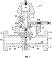
- Figure 1 illustrates a cross-sectional view of an orifice fitting with an orifice plate assembly captured in an orifice plate carrier in accordance with the principles disclosed herein.
- An orifice fitting is a type of meter that determines flow rates by measuring the pressure differential across a particularly-sized orifice.
- orifice fitting 10 includes a body 11 having a lower portion 16 coupled to an upper portion 18.
- Lower portion 16 includes a conduit or tubular member 54 having a flange 14 disposed at both ends and a housing 56 disposed therebetween.
- Flanges 14 of tubular member 54 couple orifice fitting 10 between sections of a fluid-carrying pipeline (not shown).
- Tubular member 54 also includes an axial flowbore 62 extending therethrough, characterized by a central axis 60 and upstream and downstream regions 66, 64, respectively.
- a fluid may flow through flowbore 62 from upstream region 66 to downstream region 64 generally in the direction indicated by arrow 68.
- Housing 56 encloses a lower chamber 20 with a lower drive 36, having a gear shaft and pinions disposed therein.
- Upper portion 18 of orifice fitting 10 encloses an upper chamber 22 with an upper drive 38, also having a gear shaft and pinions disposed therein.
- An orifice plate carrier 70 capturing an embodiment of an orifice plate assembly 100 may be raised and lowered within orifice fitting 10 by operating lower drive 36 and upper drive 38. In this illustration, plate carrier 70 is fully inserted into orifice fitting 10. When plate carrier 70 is fully inserted into orifice fitting 10 as shown in Figure 1 , orifice plate assembly 100 is disposed between a pair of axially spaced annular seat faces 58 of tubular member 54. An axially extending gap having a distance D1 is formed between the pair of seat faces 58. As will be described further herein, orifice plate assembly 100 is configured to seal against seat faces 58 of tubular member 54 to restrict fluid communication between lower chamber 20 and flowbore 62.
- orifice plate assembly 100 includes an orifice plate having a centrally disposed aperture extending therethrough, allowing for fluid to flow through orifice plate assembly 100 between upstream region 66 and downstream region 64 while creating a pressure drop between regions 66, 64, respectively. Also, while in this embodiment orifice plate assembly 100 is used in orifice plate fitting 10, in other embodiments orifice plate assembly 100 may be used in other orifice fittings or other tools for creating a pressure differential in a fluid flow.
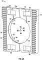
- plate carrier 70 includes a rectangular body 72 having two parallel toothed racks 74 disposed along opposing lateral sides of body 72.
- body 72 comprises metal, such as stainless steel.
- Racks 74 interface with lower drive 36 and upper drive 38 to enable the vertical displacement of plate carrier 70 within orifice fitting 10.
- Plate carrier 70 further includes a centrally disposed opening 76 defined by a generally cylindrical inner surface 78, and a plurality of flow ports 80, each extending through body 72.
- flow ports 80 allow fluid flow therethrough when plate carrier 70 is displaced into and out of position within flowbore 62 of fitting 10.
- body 72 includes four circumferentially spaced flow ports 80, each having a generally rectangular shape with beveled corners. While body 72 includes four flow ports 80 in this embodiment, there may be fewer or more flow ports 80 in other embodiments. Moreover, flow ports 80 may take other physical shapes and positions within body 72.
- Downstream face 70a of body 72 includes a retaining lip 82 and a plurality of circumferentially spaced notches 84 radially extending inward from inner surface 78 of central opening 76.
- retaining lip 82 extends radially inwards from inner surface 78 at downstream face 70a, while notches 84 extend radially inwards from inner surface 78 between downstream face 70a and an upstream face 70b of body 72.
- notches 84 extend axially (i.e., with respect to central axis 60) between faces 70a and 70b while retaining lip 82 is disposed at downstream face 70a.
- Retaining lip 82 and notches 84 are also shown in Figure 2B , which is a view of the upstream face 70b of plate carrier 70.
- retaining lip 82 and/or notches 84 are integral to body 72.
- retaining lip 82 and inner surface 78 bound an axially extending recess 86.
- orifice plate assembly 100 may be inserted into the upstream face 70b of body 72 via central opening 76 of plate carrier 70 to seat in recess 86 and abut retaining lip 82, as shown in Figure 3 .
- Notches 84 do not extend circumferentially along the full circumference of inner surface 78 of body 72, as does retaining lip 82, but instead are positioned at circumferentially spaced angular positions of 45 degrees, 135 degrees, 225 degrees, and 315 degrees, measured from a horizontal line 88 extending from the center 90 of opening 76.
- Each notch 84 has a height configured to engage an outer circumferential surface of orifice plate assembly 100, when orifice plate assembly 100 is inserted into plate carrier 70.
- notches 84 comprise metal, such as stainless steel, to provide metal-to-metal contact between each notch 84 and the orifice plate.
- orifice plate assembly 100 may be received or coupled with other orifice plate carriers or other devices for receiving orifice plate assembly 100.
- orifice plate assembly 100 generally includes a pair of identical compression rings 110 configured to capture or receive an orifice plate 200 disposed therebetween.
- an orifice plate assembly may only comprise a pair of compression rings 110 to be assembled with an orifice plate 200 prior to installation in plate carrier 70.
- Orifice plate 200 is removably disposed between the pair of compression rings 110.
- orifice plate 200 is a generally thin or flat disk and includes a generally circular or disk shaped body 202 having front and rear facing surfaces 204, a radially outer cylindrical surface 206, and a centrally disposed aperture 208 extending axially (relative horizontal line 88) therethrough.
- each compression ring 110 includes an annular elastomer seal ring 150 molded thereon for creating an annular seal between each compression ring 110 and a corresponding facing surface 204 of orifice plate 200.
- seal ring 150 is formed from a molded elastomer material, such as fluroelsastomer (FKM).
- FKM fluroelsastomer
- seal ring 150 may comprise other molded elastomeric compunds, such as Hydrogenated Nitrile Butadiene Rubber (HNBR).
- HNBR Hydrogenated Nitrile Butadiene Rubber
- seal rings 150 of compression rings 110 also form an annular seal against seat faces 58 of tubular member 54 to restrict fluid communication between lower chamber 20 and flowbore 62. In this arrangement, the entire fluid flow through flowbore 62 is directed through aperture 208 of orifice plate 200.
- Orifice plate 200 is securely held and aligned between compression rings 110 by one or more fasteners or snaps 132 that clamp the outer radial portions of each compression ring 110 to the opposing or mating compression ring 110, thereby holding orifice plate assembly 100 together. Further, each snap 132 holds compression rings 110 and orifice plate 200 together, such that orifice plate assembly 100 may be disposed in plate carrier 70 and installed in orifice fitting 10.
- Orifice plate bore 208 is machined from orifice plate 200.
- Orifice plate bore 208 has a diameter less than the diameter of passage 62 of orifice fitting 10. In this manner, fluid flow from upstream region 66 to downstream region 64 is restricted by the relative small diameter of orifice plate bore 208. As a result, the fluid pressure upstream orifice plate 200 is greater than the fluid pressure downstream of orifice plate 200.
- Small access pressure ports or pressure taps may be provided on each side of orifice plate 200 to permit the measurement of pressure differentials across orifice plate 200. The measured pressure differentials may be then used to calculate fluid flow rate through orifice fitting 10 shown in Figure 1 .
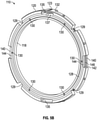
- compression ring 110 generally includes an annular body 112 having an inner facing surface 114, an outer facing surface 116, an inner cylindrical surface 118, and an outer generally cylindrical surface 120.
- Inner cylindrical surface 118 of body 112 includes a first annular bore or recess 122 that extends axially (relative horizontal line 88) into inner facing surface 114.
- First annular recess 122 extends radially from inner surface 118, forming an annular shoulder 124 proximal outer surface 120.
- Inner cylindrical surface 118 further includes an annular counterbore or groove 126 between inner surface 118 and outer surface 120 that extends axially (relative horizontal line 88) into the first annular recess 122.
- Body 112 also includes an outer annular groove 128 that extends axially into outer facing surface 116.
- Inner surface groove 126 is substantially radially aligned (i.e., has substantially the same diameter) with outer surface groove 128 and is defined by a pair of annular shoulders 127 (shown in Figure 7A ).
- Body 112 further includes a plurality of circumferentially spaced injection ports 130 that extend axially between inner surface groove 126 and outer surface groove 128 to provide for fluid communication between grooves 126 and 128. In this embodiment, body 112 includes six injection ports 130 circumferentially spaced approximately 60 degrees apart. However, in other embodiments the body 112 of each compression ring 110 may include a different number of injection ports 130 spaced at different circumferential intervals.
- Body 112 also includes a plurality of circumferentially spaced arcuate grooves 129 extending radially into generally cylindrical outer surface 120 and axially between inner facing surface 114 and outer facing surface 116.
- compression ring 110 comprises four circumferentially spaced arcuate grooves 129, spaced approximately 90 degrees apart; however, in other embodiments compression ring 110 may comprise varying number of grooves 129, where grooves 129 are not equidistantly spaced.
- arcuate grooves 129 extend radially through annular shoulder 124 and into first annular recess 122. Arcuate grooves 129 are configured to allow orifice plate assembly 100 to be inserted into central opening 76 of plate carrier 70.
- arcuate grooves 129 receive notches 84 of plate carrier 70 as orifice plate assembly 100 is inserted into central opening 76, as shown in Figure 3 .
- Each compression ring 110 includes a pair of circumferentially spaced snaps or arms 132 extending axially (relative horizontal line 88) from inner facing surface 114 for coupling with a pair of circumferentially spaced, arcuate snap engagement segments or recesses 140 that extend radially into outer cylindrical surface 120.
- each compression ring 110 includes two snaps 132 spaced approximately 180 degrees apart, and two snap engagement segments 140 spaced approximately 180 degrees apart, where each snap 132 is circumferentially spaced approximately 90 degrees from a snap engagement segment 140; however, in other embodiments compression 110 may include varying numbers of snaps 132 and snap engagement segments 140 circumferentially spaced at varying intervals.
- Each snap 132 of compression ring 110 is configured to releasably engage or couple with a corresponding snap engagement segment 140 of an opposing or mating compression ring 110.
- the two snaps 132 of a first compression ring 110 are received by and couple with two snap engagement segments 140 of a second or opposing compression ring 110.
- two opposing or mating compression rings 110 may couple about a received orifice plate 200 to form orifice plate assembly, as shown in Figure 4 .
- each snap 132 generally extends axially from inner facing surface 114 and includes a radially extending hook or latch 134 at a terminal end thereof. Further, an arcuate groove 135 circumferentially aligned with snap 132 is formed in compression ring 110 and is defined by an arcuate inner surface 137. Each arcuate snap engagement segment 140 includes a first arcuate groove 142 extending into outer cylindrical surface 120 of body 112 between inner facing surface 114 and outer facing surface 116.
- Snap engagement segment 140 also includes a second arcuate groove 142 extending into outer cylindrical surface 120 of body 112, and extending axially (relative horizontal line 88) from outer facing surface 116, forming an annular shoulder 146 axially between first groove 142 and second groove 144.
- first groove 142 when snap 132 is in the locked position (shown in Figures 7A and 7B ) an outer surface of first groove 142 is disposed proximal an inner surface 136 of snap 132, and a terminal end 138 of latch 134 is disposed proximal second groove 144.
- snap 132 is integral with compression ring 110
- latch 134 is integral with snap 132
- latch 134 when viewed through its cross-section, generally has the shape of a hook.
- latch 134 may have any suitable geometry permitting releasable engagement with compression ring 110.
- snap 132 is effectively cantilevered from the inner facing surface 114 of compression ring 110.
- snap 132 behaves like a resilient spring when flexed relative to compression ring 110.
- snap 132 when snap 132 is flexed in the direction of arrow 139, snap 132 generates a restoring force generally in the direction of arrow 141.
- This spring-like characteristic of snap 132 aids in maintaining 132 in the "locked position" shown in Figures 7A and 7B .
- a plurality of spring snaps 132 thus are employed to secure together or unlock compression rings 110 and orifice place 200.
- compression rings 110 are injection molded from Polytetrafluoroethylene, otherwise known as polytetrafluoroethylene (PTFE), or other similar material known in the industry.
- compression rings 110 may be injected molded from other thermoplastic materials, such as Polyoxymethylene (POM) or Poly ether ether ketone (PEEK). The injection molding of compression rings 110 permits reduced manufacturing costs in comparison to levels associated with machining these parts from bar stock.
- PTFE polytetrafluoroethylene
- PEEK Poly ether ether ketone
- injection molding enables the production of compression rings 110 to within tight design tolerances, thereby reducing the possibility of leakage and/or unintentional disassembly when a plate carrier holding an orifice plate assembly including compression rings 110 is handled when either removing or installing the orifice plate assembly within an orifice fitting.
- PTFE is particularly suited for exposure to highly corrosive fluids.
- the elastic behavior of PTFE enables snaps 132 to provide a secure locking mechanism for orifice plate assembly 100, even after repeated assembly, disassembly, and reassembly of orifice plate assembly 100.
- each compression ring 110 includes an annular seal ring 150 molded thereon for sealing against orifice plate 200 and the seat faces 58 of tubular member 54.
- material forming seal ring 150 may be flowed or injected through injection ports 130 of compression ring 110 to form seal ring 150.
- the molding process results in a seal ring 150 molded to compression ring 110 and generally including an outer annular seal 152 and an inner annular seal 170 integrally connected via a plurality of axially (relative horizontal line 88) extending links 180.
- Outer annular seal 152 generally includes an outer facing surface 154, an inner facing surface 156, a radially outer end 158, and a radially inner end 160.
- Radially outer end 158 of outer annular seal 152 has a diameter that is similar but slightly less than the diameter of inner surface 137 of arcuate groove 135 and radially inner end 160 has a diameter substantially the same as the diameter of inner surface 118 of compression ring 110.
- inner annular seal 170 is disposed in inner surface groove 126 of body 112 and includes an annular sealing surface 172 for engagement with a facing surface 204 of orifice plate 200.
- Inner annular seal 170 is captured within inner surface groove 126 via annular shoulders 127.
- annular shoulders 127 of inner surface groove 126 may apply a compressive force against inner annular seal 170, and in turn, apply a pressure load between facing surface 204 of orifice plate 200 and annular sealing surface 172 of inner annular seal 170.
- compression rings 110 are identical.
- orifice plate assembly 100 including identical first compression rings 110 and accompanying seal rings 150, is bi-directional.
- a bi-directional orifice plate assembly may be inserted into plate carrier 70 with either compression ring 110 facing upstream, i.e. either of the two compression rings 110 may be adjacent to upstream region 66.
- the orifice plate assembly 100 may be flipped one-hundred and eighty degrees so that the other compression ring 110 contacts plate carrier 70 instead.
- the service life of the bi-directional orifice plate assembly may be extended substantially beyond that of a conventional uni-directional orifice plate assembly.
- such flipping will have no impact to the accuracy of pressure measurements, and therefore, calculated fluid flows.
- Orifice plate assembly 100 may be assembled as shown in Figures 7A and 7B by disposing orifice plate 200 between first and second uncoupled compression rings 110, and subsequently coupling together compression rings 110 via snaps 132. In this assembled configuration, orifice plate assembly 100 may be successfully installed and removed from orifice fitting 10. Specifically, orifice plate 200 may be radially aligned about horizontal line 88 with respect to the pair of compression rings 110, such that an outer radial edge of orifice plate 200 is disposed within the first annular recess 122 of each compression ring 110, with outer cylindrical surface 206 disposed proximal annular shoulders 124.
- the two snaps 132 of the first compression ring 110 may be releasably coupled (such as by hand) or clamped to the corresponding snap engagement segments 140, thereby releasably coupling the first compression ring 110 to the second compression ring 110 with the orifice plate 200 disposed therebetween.
- orifice plate assembly 100 may be inserted into orifice plate carrier 70.
- projections 123 circumferentially spaced along the outer surface of each compression ring 110, enable orifice plate assembly 100 to fit snugly within orifice plate carrier 70, eliminating or restricting movement of orifice plate assembly 100 within plate carrier 70, including rotation of orifice plate assembly 100 about horizontal line 88.
- Projections 123 extend radially outward from outer surface 120 and may take many forms, including those shapes illustrated in Figure 6 . Also, projections 123 may be uniformly circumferentially distributed along outer surface 120 of compression rings 110 in some embodiments, while not uniformly distributed in others.
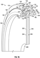
- an axially extending gap having a distance D2 (shown in Figure 7A ) is disposed between the outer annular seal 152 of each seal ring 150.
- the distance D2 between corresponding outer annular seals 152 is greater than the distance D1 between the corresponding annular seat faces 58 of tubular member 54.
- annular seat faces 58 apply a compressive force against outer annular seals 152, which is transferred to the inner annular seal 170 of the corresponding compressive rings 110, causing inner annular seals 170 to physically engage corresponding first and second facing surfaces 204 of orifice plate 200.
- annular shoulders 127 of each inner surface groove 126 also act against inner annular seals 170, thereby compressing the annular sealing surface 172 of each inner annular seal 170 to provide a fluid seal between annular sealing surfaces 172 and the facing surfaces 204 of orifice plate 200.
- engagement between each outer annular seal 152 and corresponding annular seat face 58 creates an annular seal between each outer annular seal 152 and contacting annular seat face 58. In this manner, fluid communication between lower chamber 20 and flowbore 62 is restricted.
Landscapes
- Physics & Mathematics (AREA)
- Fluid Mechanics (AREA)
- General Physics & Mathematics (AREA)
- Gasket Seals (AREA)
- Infusion, Injection, And Reservoir Apparatuses (AREA)
- Diaphragms And Bellows (AREA)
Description
- This application claims benefit of
U.S. patent application Serial No. 14/824,246 filed August 12, 2015 - Fluid flow rate is the quantification of bulk fluid or gas movement, typically measured as volumetric and mass flow rates. The ability to measure reliably and accurately fluid flow rates serves an important function in a variety of processes and industries (e.g., chemical processing, oil and gas transport and production, etc.). An orifice fitting is one of many devices that may be used to measure volumetric or mass flow rate of fluids flowing through a pipe or conduit. An orifice fitting typically employs a flat, thin plate having a central orifice that is smaller in diameter than the diameter of the conduit in which the plate is disposed. The orifice plate is positioned between a sealing ring and a compression ring that may be held together by a fastener to form an orifice plate assembly. The orifice plate assembly is disposed within a plate carrier, which is, in turn, supported and aligned within the orifice fitting. In this arrangement, the mass fluid flow rate through the conduit may be calculated from the pressure differential measured across the orifice plate, as well as other parameters.
- When using an orifice fitting to measure fluid flow, many factors must be considered in order to obtain accurate flow estimates. Typically, the orifice plate assembly is positioned within the orifice fitting with the seal and compression rings positioned on the upstream and downstream sides, respectively, of the orifice plate. A seal is provided between the seal ring and orifice plate, but no seal is provided between the orifice plate and the compression ring. With these unidirectional orifice plate assemblies, leakage may occur if the compression ring side of the orifice plate assembly is inadvertently positioned upstream. Leakage results in reduced pressure drop across the orifice plate and inaccurate estimations of fluid flow through the fitting.
-
- An embodiment of an orifice plate assembly comprises a plurality of ring members, each having an inner facing surface comprising a first annular recess extending therein, an orifice plate captured between the plurality of ring members, and a plurality of inner annular seals, wherein a different inner annular seal of the plurality of inner annular seals is overmolded to the first annular recess of each of the plurality of ring members to seal against a facing surface of the orifice plate. In an embodiment, each ring member comprises a plastic material and each inner annular seal comprises an elastomeric material. In an embodiment, each ring member comprises an outer facing surface having a second annular recess extending therein, and an outer annular seal overmolded to the second annular recess. In this embodiment, each ring member comprises a plurality of circumferentially spaced ports extending between the first annular recess and the second annular recess. In this embodiment, the orifice plate assembly further comprises an elastomeric element disposed in each port coupling the inner annular seal to the outer annular seal. In an embodiment, the inner annular seal, outer annular seal, and each elastomeric element disposed in each port of each ring member is overmolded to a ring member. In an embodiment, the first annular recess of each ring member comprises a pair of opposing annular shoulders for compressing the inner annular seal against a facing surface of the orifice plate captured between the plurality of ring members. In this embodiment, coupling a first of the plurality of ring members to a second of the plurality of ring members with an orifice plate disposed therebetween compresses the inner annular seal of the ring members against facing surfaces of the orifice plate.
- An embodiment of an orifice plate assembly comprises a plurality of ring members, each including an outer facing surface and an inner facing surface, wherein the outer facing surface comprises a first annular recess extending therein, the inner facing surface comprises a second annular recess extending therein, and each of the ring members comprises a plurality of ports extending between the first annular recess and the second annular recess, and a plurality of seal rings, each of the plurality being molded to one of the plurality of ring members, wherein each seal ring comprises an inner annular seal to seal against a facing surface of an orifice plate captured between the plurality of ring members. In an embodiment, each seal ring is overmolded to each ring member. In an embodiment, each ring member comprises a plastic material and each seal ring comprises an elastomeric material. In this embodiment, the seal ring comprises an outer annular seal disposed in the second annular recess of each ring member. In this embodiment, each seal ring comprises an elastomeric element extending through a port of each ring member. In an embodiment, the first annular recess of each ring member comprises a pair of opposing annular shoulders for compressing the inner annular seal against a facing surface of the orifice plate captured between the plurality of ring members. In an embodiment, coupling a first of the plurality of ring members to a second of the plurality of ring members with an orifice plate disposed therebetween compresses the inner annular seal of the ring members against facing surfaces of the orifice plate.
- An embodiment of an orifice fitting comprises a tubular body having a through passage, and an orifice plate assembly removably disposed within the tubular body across the through passage, the orifice plate assembly comprising an orifice plate disposed between a pair of ring members, wherein each ring member comprises an inner facing surface comprising a first annular recess extending therein, and wherein each ring member comprises an inner annular seal overmolded to the first annular recess of the ring member to seal against a facing surface of the orifice plate. In an embodiment, each ring member comprises an outer facing surface having a second annular recess extending therein, and an outer annular seal overmolded to the second annular recess. In an embodiment, each ring member comprises a plurality of circumferentially spaced ports extending between the first annular recess and the second annular recess. In this embodiment, the orifice fitting further comprises an elastomeric element disposed in each port coupling the inner annular seal to the outer annular seal. In this embodiment, each ring member comprises an outer annular seal, and wherein a distance between the outer annular seals of the orifice plate assembly is greater than the distance between a pair of annular seat faces of the tubular body.
- The foregoing has outlined rather broadly features of disclosed embodiments in order that the detailed description that follows may be better understood. Additional features will be described hereinafter that form the subject of certain of the claims.
- For a detailed description of the various exemplary embodiments disclosed herein, reference will now be made to the accompanying drawings in which:
-
Figure 1 illustrates a cross-sectional view of an orifice fitting having an orifice plate assembly in accordance with principles described herein; -
Figure 2A is a perspective view of the downstream face of the orifice plate carrier ofFigure 1 ; -
Figure 2B is a perspective view of the upstream face of the orifice plate carrier ofFigure 1 ; -
Figure 3 is a perspective view of the orifice plate assembly ofFigure 1 disposed in the orifice plate carrier ofFigures 2A and2B in accordance with principles disclosed herein; -
Figure 4 is a perspective view of the orifice plate assembly ofFigure 1 ; -
Figure 5A is a perspective view of an inner face of a compression ring of the orifice plate assembly ofFigure 1 in accordance with principles disclosed herein; -
Figure 5B is a perspective view of an outer face of a compression ring of the orifice plate assembly ofFigure 1 in accordance with principles disclosed herein; -
Figure 6 is a cross-sectional view along lines 6-6 of the compression ring ofFigure 5A ; -
Figure 7A is a perspective cross-sectional view along lines 7-7 of the orifice plate assembly ofFigure 4 ; and -
Figure 7B is a front cross-sectional view along lines 7-7 of the orifice plate assembly ofFigure 4 . - The following discussion is directed to various exemplary embodiments of the invention. One skilled in the art will understand that the following description has broad application, and the discussion of any embodiment is meant only to be exemplary of that embodiment, and not intended to intimate that the scope of the disclosure, including the claims, is limited to that embodiment, the scope of the invention being defined by the appended claims.
- The drawing figures are not necessarily to scale. Certain features of the disclosed embodiments may be shown exaggerated in scale or in somewhat schematic form, and some details of conventional elements may not be shown, all in the interest of clarity and conciseness. In the following discussion and in the claims, the terms "including" and "comprising" are used in an open-ended fashion, and thus should be interpreted to mean "including, but not limited to...." Also, the term "couple" or "couples" is intended to mean either an indirect or direct connection. Thus, if a first device couples to a second device, that coupling may be through a direct connection of the two devices, or through an indirect connection, existing via the interconnection of other intermediate devices and connections.
-
Figure 1 illustrates a cross-sectional view of an orifice fitting with an orifice plate assembly captured in an orifice plate carrier in accordance with the principles disclosed herein. An orifice fitting is a type of meter that determines flow rates by measuring the pressure differential across a particularly-sized orifice. In this embodiment,orifice fitting 10 includes abody 11 having alower portion 16 coupled to anupper portion 18.Lower portion 16 includes a conduit ortubular member 54 having aflange 14 disposed at both ends and ahousing 56 disposed therebetween.Flanges 14 oftubular member 54 couple orifice fitting 10 between sections of a fluid-carrying pipeline (not shown).Tubular member 54 also includes anaxial flowbore 62 extending therethrough, characterized by acentral axis 60 and upstream anddownstream regions flowbore 62 fromupstream region 66 todownstream region 64 generally in the direction indicated byarrow 68.Housing 56 encloses alower chamber 20 with alower drive 36, having a gear shaft and pinions disposed therein.Upper portion 18 of orifice fitting 10 encloses anupper chamber 22 with anupper drive 38, also having a gear shaft and pinions disposed therein. - An
orifice plate carrier 70 capturing an embodiment of anorifice plate assembly 100 may be raised and lowered within orifice fitting 10 by operatinglower drive 36 andupper drive 38. In this illustration,plate carrier 70 is fully inserted into orifice fitting 10. Whenplate carrier 70 is fully inserted into orifice fitting 10 as shown inFigure 1 ,orifice plate assembly 100 is disposed between a pair of axially spaced annular seat faces 58 oftubular member 54. An axially extending gap having a distance D1 is formed between the pair of seat faces 58. As will be described further herein,orifice plate assembly 100 is configured to seal against seat faces 58 oftubular member 54 to restrict fluid communication betweenlower chamber 20 andflowbore 62. Also as will be described further herein,orifice plate assembly 100 includes an orifice plate having a centrally disposed aperture extending therethrough, allowing for fluid to flow throughorifice plate assembly 100 betweenupstream region 66 anddownstream region 64 while creating a pressure drop betweenregions orifice plate assembly 100 is used in orifice plate fitting 10, in other embodiments orificeplate assembly 100 may be used in other orifice fittings or other tools for creating a pressure differential in a fluid flow. - Referring now to
Figure 2A , which depicts a view of thedownstream face 70a ofplate carrier 70, or in other words, theface 70a ofplate carrier 70 that is disposed adjacentdownstream region 64 whenplate carrier 70 is inserted into orifice fitting 10. In this embodiment,plate carrier 70 includes arectangular body 72 having two paralleltoothed racks 74 disposed along opposing lateral sides ofbody 72. In at least some embodiments,body 72 comprises metal, such as stainless steel.Racks 74 interface withlower drive 36 andupper drive 38 to enable the vertical displacement ofplate carrier 70 within orifice fitting 10.Plate carrier 70 further includes a centrally disposedopening 76 defined by a generally cylindricalinner surface 78, and a plurality offlow ports 80, each extending throughbody 72. - Referring to
Figures 2A ,2B and3 , flowports 80 allow fluid flow therethrough whenplate carrier 70 is displaced into and out of position withinflowbore 62 of fitting 10. In this embodiment,body 72 includes four circumferentially spacedflow ports 80, each having a generally rectangular shape with beveled corners. Whilebody 72 includes fourflow ports 80 in this embodiment, there may be fewer ormore flow ports 80 in other embodiments. Moreover, flowports 80 may take other physical shapes and positions withinbody 72.Downstream face 70a ofbody 72 includes a retaininglip 82 and a plurality of circumferentially spacednotches 84 radially extending inward frominner surface 78 ofcentral opening 76. - Specifically, retaining
lip 82 extends radially inwards frominner surface 78 atdownstream face 70a, whilenotches 84 extend radially inwards frominner surface 78 betweendownstream face 70a and anupstream face 70b ofbody 72. In other words,notches 84 extend axially (i.e., with respect to central axis 60) betweenfaces lip 82 is disposed atdownstream face 70a. Retaininglip 82 andnotches 84 are also shown inFigure 2B , which is a view of theupstream face 70b ofplate carrier 70. In some embodiments, including those depicted byFigures 2A and2B , retaininglip 82 and/ornotches 84 are integral tobody 72. In this embodiment, retaininglip 82 andinner surface 78 bound an axially extendingrecess 86. Thus,orifice plate assembly 100 may be inserted into theupstream face 70b ofbody 72 viacentral opening 76 ofplate carrier 70 to seat inrecess 86 andabut retaining lip 82, as shown inFigure 3 . -
Notches 84 do not extend circumferentially along the full circumference ofinner surface 78 ofbody 72, as does retaininglip 82, but instead are positioned at circumferentially spaced angular positions of 45 degrees, 135 degrees, 225 degrees, and 315 degrees, measured from ahorizontal line 88 extending from thecenter 90 ofopening 76. Eachnotch 84 has a height configured to engage an outer circumferential surface oforifice plate assembly 100, whenorifice plate assembly 100 is inserted intoplate carrier 70. In at least some embodiments,notches 84 comprise metal, such as stainless steel, to provide metal-to-metal contact between eachnotch 84 and the orifice plate. Further, while in this embodimentorifice plate assembly 100 is shown received or captured inorifice plate carrier 70, in other embodiments,orifice plate assembly 100 may be received or coupled with other orifice plate carriers or other devices for receivingorifice plate assembly 100. - Referring to
Figure 4 ,orifice plate assembly 100 generally includes a pair of identical compression rings 110 configured to capture or receive anorifice plate 200 disposed therebetween. However, in other embodiments an orifice plate assembly may only comprise a pair of compression rings 110 to be assembled with anorifice plate 200 prior to installation inplate carrier 70.Orifice plate 200 is removably disposed between the pair of compression rings 110. In this embodiment,orifice plate 200 is a generally thin or flat disk and includes a generally circular or disk shapedbody 202 having front and rear facing surfaces 204, a radially outercylindrical surface 206, and a centrally disposedaperture 208 extending axially (relative horizontal line 88) therethrough. As will be described further herein, compression rings 110 couple to orificeplate 200 via engagement with a radially outer portion of facingsurfaces 204 proximal outercylindrical surface 206. More specifically, eachcompression ring 110 includes an annularelastomer seal ring 150 molded thereon for creating an annular seal between eachcompression ring 110 and a corresponding facingsurface 204 oforifice plate 200. In this embodiment,seal ring 150 is formed from a molded elastomer material, such as fluroelsastomer (FKM). In other embodiments,seal ring 150 may comprise other molded elastomeric compunds, such as Hydrogenated Nitrile Butadiene Rubber (HNBR). Moreover, seal rings 150 of compression rings 110 also form an annular seal against seat faces 58 oftubular member 54 to restrict fluid communication betweenlower chamber 20 andflowbore 62. In this arrangement, the entire fluid flow throughflowbore 62 is directed throughaperture 208 oforifice plate 200. -
Orifice plate 200 is securely held and aligned between compression rings 110 by one or more fasteners or snaps 132 that clamp the outer radial portions of eachcompression ring 110 to the opposing ormating compression ring 110, thereby holdingorifice plate assembly 100 together. Further, eachsnap 132 holds compression rings 110 andorifice plate 200 together, such thatorifice plate assembly 100 may be disposed inplate carrier 70 and installed in orifice fitting 10. - Orifice plate bore 208 is machined from
orifice plate 200. Orifice plate bore 208 has a diameter less than the diameter ofpassage 62 of orifice fitting 10. In this manner, fluid flow fromupstream region 66 todownstream region 64 is restricted by the relative small diameter of orifice plate bore 208. As a result, the fluid pressureupstream orifice plate 200 is greater than the fluid pressure downstream oforifice plate 200. Small access pressure ports or pressure taps (not shown) may be provided on each side oforifice plate 200 to permit the measurement of pressure differentials acrossorifice plate 200. The measured pressure differentials may be then used to calculate fluid flow rate through orifice fitting 10 shown inFigure 1 . - Referring to
Figures 5A ,5B , and6 , in thisembodiment compression ring 110 generally includes anannular body 112 having an inner facingsurface 114, an outer facingsurface 116, an innercylindrical surface 118, and an outer generallycylindrical surface 120. Innercylindrical surface 118 ofbody 112 includes a first annular bore orrecess 122 that extends axially (relative horizontal line 88) into inner facingsurface 114. Firstannular recess 122 extends radially frominner surface 118, forming anannular shoulder 124 proximalouter surface 120. Innercylindrical surface 118 further includes an annular counterbore or groove 126 betweeninner surface 118 andouter surface 120 that extends axially (relative horizontal line 88) into the firstannular recess 122.Body 112 also includes an outerannular groove 128 that extends axially into outer facingsurface 116.Inner surface groove 126 is substantially radially aligned (i.e., has substantially the same diameter) withouter surface groove 128 and is defined by a pair of annular shoulders 127 (shown inFigure 7A ).Body 112 further includes a plurality of circumferentially spacedinjection ports 130 that extend axially betweeninner surface groove 126 andouter surface groove 128 to provide for fluid communication betweengrooves body 112 includes sixinjection ports 130 circumferentially spaced approximately 60 degrees apart. However, in other embodiments thebody 112 of eachcompression ring 110 may include a different number ofinjection ports 130 spaced at different circumferential intervals. -
Body 112 also includes a plurality of circumferentially spacedarcuate grooves 129 extending radially into generally cylindricalouter surface 120 and axially between inner facingsurface 114 and outer facingsurface 116. In this embodiment,compression ring 110 comprises four circumferentially spacedarcuate grooves 129, spaced approximately 90 degrees apart; however, in otherembodiments compression ring 110 may comprise varying number ofgrooves 129, wheregrooves 129 are not equidistantly spaced. In this embodiment,arcuate grooves 129 extend radially throughannular shoulder 124 and into firstannular recess 122.Arcuate grooves 129 are configured to alloworifice plate assembly 100 to be inserted intocentral opening 76 ofplate carrier 70. Specifically,arcuate grooves 129 receivenotches 84 ofplate carrier 70 asorifice plate assembly 100 is inserted intocentral opening 76, as shown inFigure 3 . The reception ofnotches 84 in correspondingarcuate grooves 129 disposedorifice plate assembly 100 within orifice fitting 10 such thatorifice plate assembly 100 is disposed coaxially withcentral axis 60 ofaxial flowbore 62. - Each
compression ring 110 includes a pair of circumferentially spaced snaps orarms 132 extending axially (relative horizontal line 88) from inner facingsurface 114 for coupling with a pair of circumferentially spaced, arcuate snap engagement segments or recesses 140 that extend radially into outercylindrical surface 120. In this embodiment, eachcompression ring 110 includes twosnaps 132 spaced approximately 180 degrees apart, and twosnap engagement segments 140 spaced approximately 180 degrees apart, where eachsnap 132 is circumferentially spaced approximately 90 degrees from asnap engagement segment 140; however, inother embodiments compression 110 may include varying numbers ofsnaps 132 and snapengagement segments 140 circumferentially spaced at varying intervals. Eachsnap 132 ofcompression ring 110 is configured to releasably engage or couple with a correspondingsnap engagement segment 140 of an opposing ormating compression ring 110. In other words, the twosnaps 132 of afirst compression ring 110 are received by and couple with twosnap engagement segments 140 of a second or opposingcompression ring 110. In this manner, two opposing or mating compression rings 110 may couple about a receivedorifice plate 200 to form orifice plate assembly, as shown inFigure 4 . - In the embodiment shown in
Figures 5A ,5B , and6 , eachsnap 132 generally extends axially from inner facingsurface 114 and includes a radially extending hook or latch 134 at a terminal end thereof. Further, anarcuate groove 135 circumferentially aligned withsnap 132 is formed incompression ring 110 and is defined by an arcuateinner surface 137. Each arcuatesnap engagement segment 140 includes a firstarcuate groove 142 extending into outercylindrical surface 120 ofbody 112 between inner facingsurface 114 and outer facingsurface 116.Snap engagement segment 140 also includes a secondarcuate groove 142 extending into outercylindrical surface 120 ofbody 112, and extending axially (relative horizontal line 88) from outer facingsurface 116, forming anannular shoulder 146 axially betweenfirst groove 142 andsecond groove 144. In this arrangement, whensnap 132 is in the locked position (shown inFigures 7A and7B ) an outer surface offirst groove 142 is disposed proximal aninner surface 136 ofsnap 132, and aterminal end 138 oflatch 134 is disposed proximalsecond groove 144. - Referring to
Figures 5A-7B , in this embodiment,snap 132 is integral withcompression ring 110, and latch 134 is integral withsnap 132. Also in this embodiment,latch 134, when viewed through its cross-section, generally has the shape of a hook. However, in other embodiments (not specifically illustrated),latch 134 may have any suitable geometry permitting releasable engagement withcompression ring 110. In this arrangement,snap 132 is effectively cantilevered from the inner facingsurface 114 ofcompression ring 110. As a result,snap 132 behaves like a resilient spring when flexed relative tocompression ring 110. Thus, whensnap 132 is flexed in the direction ofarrow 139,snap 132 generates a restoring force generally in the direction ofarrow 141. This spring-like characteristic ofsnap 132 aids in maintaining 132 in the "locked position" shown inFigures 7A and7B . A plurality of spring snaps 132 thus are employed to secure together or unlock compression rings 110 andorifice place 200. - In some embodiments, compression rings 110 are injection molded from Polytetrafluoroethylene, otherwise known as polytetrafluoroethylene (PTFE), or other similar material known in the industry. In other embodiments, compression rings 110 may be injected molded from other thermoplastic materials, such as Polyoxymethylene (POM) or Poly ether ether ketone (PEEK). The injection molding of compression rings 110 permits reduced manufacturing costs in comparison to levels associated with machining these parts from bar stock. In addition to reduced manufacturing costs, injection molding enables the production of compression rings 110 to within tight design tolerances, thereby reducing the possibility of leakage and/or unintentional disassembly when a plate carrier holding an orifice plate assembly including compression rings 110 is handled when either removing or installing the orifice plate assembly within an orifice fitting. PTFE is particularly suited for exposure to highly corrosive fluids. Moreover, the elastic behavior of PTFE enables
snaps 132 to provide a secure locking mechanism fororifice plate assembly 100, even after repeated assembly, disassembly, and reassembly oforifice plate assembly 100. - In the embodiment shown in
Figures 7A and7B , eachcompression ring 110 includes anannular seal ring 150 molded thereon for sealing againstorifice plate 200 and the seat faces 58 oftubular member 54. During the molding process, material formingseal ring 150 may be flowed or injected throughinjection ports 130 ofcompression ring 110 to formseal ring 150. Thus, the molding process results in aseal ring 150 molded tocompression ring 110 and generally including an outerannular seal 152 and an innerannular seal 170 integrally connected via a plurality of axially (relative horizontal line 88) extendinglinks 180. Outerannular seal 152 generally includes an outer facingsurface 154, an inner facingsurface 156, a radiallyouter end 158, and a radiallyinner end 160. Radiallyouter end 158 of outerannular seal 152 has a diameter that is similar but slightly less than the diameter ofinner surface 137 ofarcuate groove 135 and radiallyinner end 160 has a diameter substantially the same as the diameter ofinner surface 118 ofcompression ring 110. - In this embodiment, inner
annular seal 170 is disposed ininner surface groove 126 ofbody 112 and includes anannular sealing surface 172 for engagement with a facingsurface 204 oforifice plate 200. Innerannular seal 170 is captured withininner surface groove 126 viaannular shoulders 127. In this arrangement,annular shoulders 127 ofinner surface groove 126 may apply a compressive force against innerannular seal 170, and in turn, apply a pressure load between facingsurface 204 oforifice plate 200 andannular sealing surface 172 of innerannular seal 170. - As shown in
Figures 5A-7B , compression rings 110 are identical. In this embodiment,orifice plate assembly 100, including identical first compression rings 110 and accompanying seal rings 150, is bi-directional. A bi-directional orifice plate assembly may be inserted intoplate carrier 70 with eithercompression ring 110 facing upstream, i.e. either of the two compression rings 110 may be adjacent toupstream region 66. Specifically, when thecompression ring 110 in contact withplate carrier 70 becomes worn due to abrasions caused by repeated installation and removal fromplate carrier 70, theorifice plate assembly 100 may be flipped one-hundred and eighty degrees so that theother compression ring 110contacts plate carrier 70 instead. Thus, the service life of the bi-directional orifice plate assembly may be extended substantially beyond that of a conventional uni-directional orifice plate assembly. Moreover, such flipping will have no impact to the accuracy of pressure measurements, and therefore, calculated fluid flows. -
Orifice plate assembly 100 may be assembled as shown inFigures 7A and7B by disposingorifice plate 200 between first and second uncoupled compression rings 110, and subsequently coupling together compression rings 110 via snaps 132. In this assembled configuration,orifice plate assembly 100 may be successfully installed and removed from orifice fitting 10. Specifically,orifice plate 200 may be radially aligned abouthorizontal line 88 with respect to the pair of compression rings 110, such that an outer radial edge oforifice plate 200 is disposed within the firstannular recess 122 of eachcompression ring 110, with outercylindrical surface 206 disposed proximalannular shoulders 124. In this position, the twosnaps 132 of thefirst compression ring 110 may be releasably coupled (such as by hand) or clamped to the correspondingsnap engagement segments 140, thereby releasably coupling thefirst compression ring 110 to thesecond compression ring 110 with theorifice plate 200 disposed therebetween. - Once
orifice plate assembly 100 has been assembled with first and second compression rings 110 releasably coupled together withorifice plate 200 captured therebetween,orifice plate assembly 100 may be inserted intoorifice plate carrier 70. When so installed,projections 123, circumferentially spaced along the outer surface of eachcompression ring 110, enableorifice plate assembly 100 to fit snugly withinorifice plate carrier 70, eliminating or restricting movement oforifice plate assembly 100 withinplate carrier 70, including rotation oforifice plate assembly 100 abouthorizontal line 88.Projections 123 extend radially outward fromouter surface 120 and may take many forms, including those shapes illustrated inFigure 6 . Also,projections 123 may be uniformly circumferentially distributed alongouter surface 120 of compression rings 110 in some embodiments, while not uniformly distributed in others. - Also in the assembled configuration, as shown in
Figures 7A and7B , an axially extending gap having a distance D2 (shown inFigure 7A ) is disposed between the outerannular seal 152 of eachseal ring 150. The distance D2 between corresponding outerannular seals 152 is greater than the distance D1 between the corresponding annular seat faces 58 oftubular member 54. Thus, when the assembledorifice plate assembly 100 is installed within orifice fitting 10, as shown inFigure 1 , a compressive force may be applied to facingsurfaces 204 oforifice plate 200 to create an annular seal between sealingsurface 172 of theseal ring 150 of each compressingring 110 and each facingsurface 204 oforifice plate 200. - Specifically, because the distance D2 between outer
annular seals 152 of the assembledorifice plate assembly 100 is greater than the distance D1 between annular seat faces 58, the annular seat faces 58 apply a compressive force against outerannular seals 152, which is transferred to the innerannular seal 170 of the corresponding compressive rings 110, causing innerannular seals 170 to physically engage corresponding first and second facing surfaces 204 oforifice plate 200. In response to the physical engagement of innerannular seals 170 against facingsurfaces 204 oforifice plate 200,annular shoulders 127 of eachinner surface groove 126 also act against innerannular seals 170, thereby compressing theannular sealing surface 172 of each innerannular seal 170 to provide a fluid seal between annular sealing surfaces 172 and the facingsurfaces 204 oforifice plate 200. Moreover, engagement between each outerannular seal 152 and correspondingannular seat face 58 creates an annular seal between each outerannular seal 152 and contactingannular seat face 58. In this manner, fluid communication betweenlower chamber 20 andflowbore 62 is restricted. - While exemplary embodiments have been shown and described, modifications thereof can be made by one skilled in the art without departing from the scope or teaching herein. The embodiments described herein are exemplary only and are not limiting. Many variations and modifications of the system and apparatus are possible and will become apparent to those skilled in the art once the above disclosure is fully appreciated. For example, the relative dimensions of various parts, the materials from which the various parts are made, and other parameters can be varied. Furthermore, though the openings in the plate carriers are shown as circles, they may include other shapes such as ovals or squares. Accordingly, it is intended that the following claims be interpreted to embrace all such variations and modifications.
Claims (15)
- An orifice plate assembly (100) comprising:a plurality of ring members (110), each having an inner facing surface (114) comprising a first annular recess (126) extending therein; andan orifice plate (200) captured between the plurality of ring members (110);characterized bya plurality of inner annular seals (170), wherein a different inner annular seal of the plurality of inner annular seals (170) is overmolded to the first annular recess (126) of each of the plurality of ring members (110) to seal against a facing surface (204) of the orifice plate (200).
- The orifice plate assembly (100) of claim 1, wherein each ring member (110) comprises a plastic material and each inner annular seal (170) comprises an elastomeric material.
- The orifice plate assembly (100) of claim 1, wherein each ring member (110) comprises an outer facing surface (116) having a second annular recess (128) extending therein, and an outer annular seal (152) overmolded to the second annular recess (128).
- The orifice plate assembly (100) of claim 3, wherein each ring member (110) comprises a plurality of circumferentially spaced ports (130) extending between the first annular recess (126) and the second annular recess (128).
- The orifice plate assembly (100) of claim 4, further comprising an elastomeric element (180) disposed in each port (130) coupling the inner annular seal (170) to the outer annular seal (152).
- The orifice plate assembly (100) of claim 1, wherein the inner annular seal (170), outer annular seal (152), and each elastomeric element (180) disposed in each port (130) of each ring member (110) is overmolded to a ring member (110).
- The orifice plate assembly (100) of claim 1, wherein the first annular recess (126) of each ring member (110) comprises a pair of opposing annular shoulders (127) for compressing the inner annular seal (170) against a facing surface (204) of the orifice plate (200) captured between the plurality of ring members (110).
- The orifice plate assembly (100) of claim 1, wherein coupling a first of the plurality of ring members (110) to a second of the plurality of ring members (110) with an orifice plate disposed therebetween compresses the inner annular seal (170) of the ring members (110) against facing surfaces (204) of the orifice plate (200).
- The orifice plate assembly (100) of claim 1, further comprising: a plurality of seal rings (150), each of the plurality of seal rings (150) being molded to one of the plurality of ring members (110), wherein each seal ring (150) comprises one of the plurality of inner annular seals (170).
- The orifice plate assembly (100) of claim 9, wherein each seal ring (150) is overmolded to each ring member (110).
- The orifice plate assembly (100) of claim 9, wherein each ring member (110) comprises a plastic material and each seal ring (150) comprises an elastomeric material.
- The orifice plate assembly (100) of claim 9, wherein the seal ring (150) comprises an outer annular seal (152) disposed in the second annular recess (128) of each ring member (110).
- The orifice plate assembly (100) of claim 12, wherein each seal ring (150) comprises an elastomeric element (180) extending through a port (130) of each ring member (110).
- The orifice plate assembly (100) of claim 9, wherein the first annular recess (126) of each ring member (110) comprises a pair of opposing annular shoulders (127) for compressing the inner annular seal (170) against a facing surface (204) of the orifice plate (200) captured between the plurality of ring members (110).
- The orifice plate assembly (100) of claim 9, wherein coupling a first of the plurality of ring members (110) to a second of the plurality of ring members (110) with an orifice plate disposed therebetween compresses the inner annular seal (170) of the ring members (110) against facing surfaces (204) of the orifice plate (200).
Applications Claiming Priority (2)
| Application Number | Priority Date | Filing Date | Title |
|---|---|---|---|
| US14/824,246 US9933289B2 (en) | 2015-08-12 | 2015-08-12 | Orifice plate assembly |
| PCT/US2016/046473 WO2017027663A1 (en) | 2015-08-12 | 2016-08-11 | Orifice plate assembly |
Publications (3)
| Publication Number | Publication Date |
|---|---|
| EP3335015A1 EP3335015A1 (en) | 2018-06-20 |
| EP3335015A4 EP3335015A4 (en) | 2019-04-17 |
| EP3335015B1 true EP3335015B1 (en) | 2022-02-16 |
Family
ID=57983736
Family Applications (1)
| Application Number | Title | Priority Date | Filing Date |
|---|---|---|---|
| EP16835881.0A Not-in-force EP3335015B1 (en) | 2015-08-12 | 2016-08-11 | Orifice plate assembly |
Country Status (7)
| Country | Link |
|---|---|
| US (1) | US9933289B2 (en) |
| EP (1) | EP3335015B1 (en) |
| CN (1) | CN108027261A (en) |
| CA (1) | CA2995195C (en) |
| MX (1) | MX391283B (en) |
| RU (1) | RU2726029C1 (en) |
| WO (1) | WO2017027663A1 (en) |
Families Citing this family (4)
| Publication number | Priority date | Publication date | Assignee | Title |
|---|---|---|---|---|
| US10545040B2 (en) * | 2018-02-02 | 2020-01-28 | Daniel Measurment And Control, Inc. | Flowmeter and orifice plate carrier assembly therefor |
| US10794741B2 (en) * | 2018-10-06 | 2020-10-06 | Bell Technologies, LLC | Flow measurement insert and system for use with orifice fitting |
| US12013268B2 (en) | 2020-10-20 | 2024-06-18 | Tmco Operating, Llc | Orifice plate carrier |
| RU2767835C1 (en) * | 2021-10-28 | 2022-03-22 | Анатолий Петрович Горшенёв | Diaphragm meter of critical currents |
Family Cites Families (11)
| Publication number | Priority date | Publication date | Assignee | Title |
|---|---|---|---|---|
| US4393722A (en) * | 1981-06-15 | 1983-07-19 | Scott Marvin D | Flow measuring device |
| US4478251A (en) | 1982-08-02 | 1984-10-23 | Daniel Industries, Inc. | Orifice fitting seal assembly |
| US5085250A (en) * | 1990-12-18 | 1992-02-04 | Daniel Industries, Inc. | Orifice system |
| US5186474A (en) * | 1991-12-03 | 1993-02-16 | Jacobs James L | Seal ring for orifice plate |
| US5305796A (en) * | 1992-08-05 | 1994-04-26 | G-H Flow Automation, Inc. | Apparatus and method for centering an orifice plate |
| JPH06109502A (en) * | 1992-08-10 | 1994-04-19 | Daniel Ind Inc | Orifice-palte holding system |
| US5758692A (en) * | 1995-03-15 | 1998-06-02 | Crane Manufacturing, Inc. | Orifice fitting |
| CN2369218Y (en) * | 1999-04-21 | 2000-03-15 | 中国人民解放军第五七一九工厂阀门分厂 | Standard orifice assembly |
| US20060231149A1 (en) * | 2005-04-19 | 2006-10-19 | Daniel Industries, Inc. | Orifice flow meters |
| EP1962007A1 (en) * | 2007-02-22 | 2008-08-27 | Actaris SAS | Watertight seal for a flowmeter casing |
| US7461563B1 (en) * | 2007-09-07 | 2008-12-09 | Daniel Measurement And Control, Inc. | Bi-directional orifice plate assembly |
-
2015
- 2015-08-12 US US14/824,246 patent/US9933289B2/en active Active
-
2016
- 2016-08-11 WO PCT/US2016/046473 patent/WO2017027663A1/en not_active Ceased
- 2016-08-11 EP EP16835881.0A patent/EP3335015B1/en not_active Not-in-force
- 2016-08-11 CA CA2995195A patent/CA2995195C/en active Active
- 2016-08-11 MX MX2018001823A patent/MX391283B/en unknown
- 2016-08-11 CN CN201680052990.0A patent/CN108027261A/en active Pending
- 2016-08-11 RU RU2018106307A patent/RU2726029C1/en active
Also Published As
| Publication number | Publication date |
|---|---|
| MX2018001823A (en) | 2018-05-28 |
| US9933289B2 (en) | 2018-04-03 |
| WO2017027663A1 (en) | 2017-02-16 |
| EP3335015A4 (en) | 2019-04-17 |
| MX391283B (en) | 2025-03-21 |
| US20170045385A1 (en) | 2017-02-16 |
| CA2995195C (en) | 2020-07-21 |
| CA2995195A1 (en) | 2017-02-16 |
| RU2726029C1 (en) | 2020-07-08 |
| CN108027261A (en) | 2018-05-11 |
| EP3335015A1 (en) | 2018-06-20 |
Similar Documents
| Publication | Publication Date | Title |
|---|---|---|
| CA2995195C (en) | Orifice plate assembly | |
| US5085250A (en) | Orifice system | |
| US20110163540A1 (en) | O-ringless seal couplings | |
| US7461563B1 (en) | Bi-directional orifice plate assembly | |
| EP3144567B1 (en) | Dynamic sealing | |
| EP2799752B1 (en) | Multi-port rotary joint | |
| US20060231149A1 (en) | Orifice flow meters | |
| WO2013119292A1 (en) | Fitting having receptacle of varying depth | |
| US12007055B2 (en) | Compact fluid couplings | |
| JPH07500656A (en) | Orifice system sealing assembly | |
| EP3521772B1 (en) | Flowmeter and orifice plate carrier assembly therefor | |
| WO2015148143A1 (en) | Adapter for inserting wafer ring between flanges of process piping | |
| EP2242998B1 (en) | Orifice plate carrier | |
| US12392436B2 (en) | Connector and method for connecting pipes for transporting fluids | |
| US11603950B2 (en) | Development of fuseal mechanical joint | |
| AU2021234266B2 (en) | Non-metallic fluid coupling | |
| EP0516841B1 (en) | Orifice system | |
| US12013268B2 (en) | Orifice plate carrier |
Legal Events
| Date | Code | Title | Description |
|---|---|---|---|
| STAA | Information on the status of an ep patent application or granted ep patent |
Free format text: STATUS: THE INTERNATIONAL PUBLICATION HAS BEEN MADE |
|
| PUAI | Public reference made under article 153(3) epc to a published international application that has entered the european phase |
Free format text: ORIGINAL CODE: 0009012 |
|
| STAA | Information on the status of an ep patent application or granted ep patent |
Free format text: STATUS: REQUEST FOR EXAMINATION WAS MADE |
|
| 17P | Request for examination filed |
Effective date: 20180212 |
|
| AK | Designated contracting states |
Kind code of ref document: A1 Designated state(s): AL AT BE BG CH CY CZ DE DK EE ES FI FR GB GR HR HU IE IS IT LI LT LU LV MC MK MT NL NO PL PT RO RS SE SI SK SM TR |
|
| AX | Request for extension of the european patent |
Extension state: BA ME |
|
| DAV | Request for validation of the european patent (deleted) | ||
| DAX | Request for extension of the european patent (deleted) | ||
| A4 | Supplementary search report drawn up and despatched |
Effective date: 20190319 |
|
| RIC1 | Information provided on ipc code assigned before grant |
Ipc: G01F 15/18 20060101ALI20190313BHEP Ipc: G01F 1/42 20060101AFI20190313BHEP |
|
| GRAP | Despatch of communication of intention to grant a patent |
Free format text: ORIGINAL CODE: EPIDOSNIGR1 |
|
| STAA | Information on the status of an ep patent application or granted ep patent |
Free format text: STATUS: GRANT OF PATENT IS INTENDED |
|
| INTG | Intention to grant announced |
Effective date: 20211011 |
|
| GRAS | Grant fee paid |
Free format text: ORIGINAL CODE: EPIDOSNIGR3 |
|
| GRAA | (expected) grant |
Free format text: ORIGINAL CODE: 0009210 |
|
| STAA | Information on the status of an ep patent application or granted ep patent |
Free format text: STATUS: THE PATENT HAS BEEN GRANTED |
|
| AK | Designated contracting states |
Kind code of ref document: B1 Designated state(s): AL AT BE BG CH CY CZ DE DK EE ES FI FR GB GR HR HU IE IS IT LI LT LU LV MC MK MT NL NO PL PT RO RS SE SI SK SM TR |
|
| REG | Reference to a national code |
Ref country code: GB Ref legal event code: FG4D |
|
| REG | Reference to a national code |
Ref country code: CH Ref legal event code: EP |
|
| REG | Reference to a national code |
Ref country code: DE Ref legal event code: R096 Ref document number: 602016069209 Country of ref document: DE |
|
| REG | Reference to a national code |
Ref country code: AT Ref legal event code: REF Ref document number: 1469158 Country of ref document: AT Kind code of ref document: T Effective date: 20220315 |
|
| REG | Reference to a national code |
Ref country code: IE Ref legal event code: FG4D |
|
| REG | Reference to a national code |
Ref country code: NL Ref legal event code: FP |
|
| REG | Reference to a national code |
Ref country code: LT Ref legal event code: MG9D |
|
| REG | Reference to a national code |
Ref country code: AT Ref legal event code: MK05 Ref document number: 1469158 Country of ref document: AT Kind code of ref document: T Effective date: 20220216 |
|
| PG25 | Lapsed in a contracting state [announced via postgrant information from national office to epo] |
Ref country code: SE Free format text: LAPSE BECAUSE OF FAILURE TO SUBMIT A TRANSLATION OF THE DESCRIPTION OR TO PAY THE FEE WITHIN THE PRESCRIBED TIME-LIMIT Effective date: 20220216 Ref country code: RS Free format text: LAPSE BECAUSE OF FAILURE TO SUBMIT A TRANSLATION OF THE DESCRIPTION OR TO PAY THE FEE WITHIN THE PRESCRIBED TIME-LIMIT Effective date: 20220216 Ref country code: PT Free format text: LAPSE BECAUSE OF FAILURE TO SUBMIT A TRANSLATION OF THE DESCRIPTION OR TO PAY THE FEE WITHIN THE PRESCRIBED TIME-LIMIT Effective date: 20220616 Ref country code: NO Free format text: LAPSE BECAUSE OF FAILURE TO SUBMIT A TRANSLATION OF THE DESCRIPTION OR TO PAY THE FEE WITHIN THE PRESCRIBED TIME-LIMIT Effective date: 20220516 Ref country code: LT Free format text: LAPSE BECAUSE OF FAILURE TO SUBMIT A TRANSLATION OF THE DESCRIPTION OR TO PAY THE FEE WITHIN THE PRESCRIBED TIME-LIMIT Effective date: 20220216 Ref country code: HR Free format text: LAPSE BECAUSE OF FAILURE TO SUBMIT A TRANSLATION OF THE DESCRIPTION OR TO PAY THE FEE WITHIN THE PRESCRIBED TIME-LIMIT Effective date: 20220216 Ref country code: ES Free format text: LAPSE BECAUSE OF FAILURE TO SUBMIT A TRANSLATION OF THE DESCRIPTION OR TO PAY THE FEE WITHIN THE PRESCRIBED TIME-LIMIT Effective date: 20220216 Ref country code: BG Free format text: LAPSE BECAUSE OF FAILURE TO SUBMIT A TRANSLATION OF THE DESCRIPTION OR TO PAY THE FEE WITHIN THE PRESCRIBED TIME-LIMIT Effective date: 20220516 |
|
| PG25 | Lapsed in a contracting state [announced via postgrant information from national office to epo] |
Ref country code: PL Free format text: LAPSE BECAUSE OF FAILURE TO SUBMIT A TRANSLATION OF THE DESCRIPTION OR TO PAY THE FEE WITHIN THE PRESCRIBED TIME-LIMIT Effective date: 20220216 Ref country code: LV Free format text: LAPSE BECAUSE OF FAILURE TO SUBMIT A TRANSLATION OF THE DESCRIPTION OR TO PAY THE FEE WITHIN THE PRESCRIBED TIME-LIMIT Effective date: 20220216 Ref country code: GR Free format text: LAPSE BECAUSE OF FAILURE TO SUBMIT A TRANSLATION OF THE DESCRIPTION OR TO PAY THE FEE WITHIN THE PRESCRIBED TIME-LIMIT Effective date: 20220517 Ref country code: FI Free format text: LAPSE BECAUSE OF FAILURE TO SUBMIT A TRANSLATION OF THE DESCRIPTION OR TO PAY THE FEE WITHIN THE PRESCRIBED TIME-LIMIT Effective date: 20220216 Ref country code: AT Free format text: LAPSE BECAUSE OF FAILURE TO SUBMIT A TRANSLATION OF THE DESCRIPTION OR TO PAY THE FEE WITHIN THE PRESCRIBED TIME-LIMIT Effective date: 20220216 |
|
| RAP2 | Party data changed (patent owner data changed or rights of a patent transferred) |
Owner name: DANIEL OPCO, LLC |
|
| PG25 | Lapsed in a contracting state [announced via postgrant information from national office to epo] |
Ref country code: IS Free format text: LAPSE BECAUSE OF FAILURE TO SUBMIT A TRANSLATION OF THE DESCRIPTION OR TO PAY THE FEE WITHIN THE PRESCRIBED TIME-LIMIT Effective date: 20220617 |
|
| PG25 | Lapsed in a contracting state [announced via postgrant information from national office to epo] |
Ref country code: SM Free format text: LAPSE BECAUSE OF FAILURE TO SUBMIT A TRANSLATION OF THE DESCRIPTION OR TO PAY THE FEE WITHIN THE PRESCRIBED TIME-LIMIT Effective date: 20220216 Ref country code: SK Free format text: LAPSE BECAUSE OF FAILURE TO SUBMIT A TRANSLATION OF THE DESCRIPTION OR TO PAY THE FEE WITHIN THE PRESCRIBED TIME-LIMIT Effective date: 20220216 Ref country code: RO Free format text: LAPSE BECAUSE OF FAILURE TO SUBMIT A TRANSLATION OF THE DESCRIPTION OR TO PAY THE FEE WITHIN THE PRESCRIBED TIME-LIMIT Effective date: 20220216 Ref country code: EE Free format text: LAPSE BECAUSE OF FAILURE TO SUBMIT A TRANSLATION OF THE DESCRIPTION OR TO PAY THE FEE WITHIN THE PRESCRIBED TIME-LIMIT Effective date: 20220216 Ref country code: DK Free format text: LAPSE BECAUSE OF FAILURE TO SUBMIT A TRANSLATION OF THE DESCRIPTION OR TO PAY THE FEE WITHIN THE PRESCRIBED TIME-LIMIT Effective date: 20220216 Ref country code: CZ Free format text: LAPSE BECAUSE OF FAILURE TO SUBMIT A TRANSLATION OF THE DESCRIPTION OR TO PAY THE FEE WITHIN THE PRESCRIBED TIME-LIMIT Effective date: 20220216 |
|
| REG | Reference to a national code |
Ref country code: DE Ref legal event code: R097 Ref document number: 602016069209 Country of ref document: DE Ref country code: DE Ref legal event code: R081 Ref document number: 602016069209 Country of ref document: DE Owner name: DANIEL OPCO, LLC (N.D.GES.D.STAATES DELAWARE),, US Free format text: FORMER OWNER: DANIEL MEASUREMENT AND CONTROL, INC., HOUSTON, TX, US |
|
| PG25 | Lapsed in a contracting state [announced via postgrant information from national office to epo] |
Ref country code: AL Free format text: LAPSE BECAUSE OF FAILURE TO SUBMIT A TRANSLATION OF THE DESCRIPTION OR TO PAY THE FEE WITHIN THE PRESCRIBED TIME-LIMIT Effective date: 20220216 |
|
| REG | Reference to a national code |
Ref country code: NL Ref legal event code: PD Owner name: DANIEL OPCO, LLC; US Free format text: DETAILS ASSIGNMENT: CHANGE OF OWNER(S), ASSIGNMENT; FORMER OWNER NAME: DANIEL MEASUREMENT AND CONTROL, INC. Effective date: 20221206 |
|
| PLBE | No opposition filed within time limit |
Free format text: ORIGINAL CODE: 0009261 |
|
| STAA | Information on the status of an ep patent application or granted ep patent |
Free format text: STATUS: NO OPPOSITION FILED WITHIN TIME LIMIT |
|
| 26N | No opposition filed |
Effective date: 20221117 |
|
| PG25 | Lapsed in a contracting state [announced via postgrant information from national office to epo] |
Ref country code: SI Free format text: LAPSE BECAUSE OF FAILURE TO SUBMIT A TRANSLATION OF THE DESCRIPTION OR TO PAY THE FEE WITHIN THE PRESCRIBED TIME-LIMIT Effective date: 20220216 |
|
| PG25 | Lapsed in a contracting state [announced via postgrant information from national office to epo] |
Ref country code: MC Free format text: LAPSE BECAUSE OF FAILURE TO SUBMIT A TRANSLATION OF THE DESCRIPTION OR TO PAY THE FEE WITHIN THE PRESCRIBED TIME-LIMIT Effective date: 20220216 |
|
| REG | Reference to a national code |
Ref country code: CH Ref legal event code: PL |
|
| PG25 | Lapsed in a contracting state [announced via postgrant information from national office to epo] |
Ref country code: LU Free format text: LAPSE BECAUSE OF NON-PAYMENT OF DUE FEES Effective date: 20220811 Ref country code: LI Free format text: LAPSE BECAUSE OF NON-PAYMENT OF DUE FEES Effective date: 20220831 Ref country code: CH Free format text: LAPSE BECAUSE OF NON-PAYMENT OF DUE FEES Effective date: 20220831 |
|
| REG | Reference to a national code |
Ref country code: BE Ref legal event code: MM Effective date: 20220831 |
|
| REG | Reference to a national code |
Ref country code: GB Ref legal event code: 732E Free format text: REGISTERED BETWEEN 20230420 AND 20230426 |
|
| PG25 | Lapsed in a contracting state [announced via postgrant information from national office to epo] |
Ref country code: IT Free format text: LAPSE BECAUSE OF FAILURE TO SUBMIT A TRANSLATION OF THE DESCRIPTION OR TO PAY THE FEE WITHIN THE PRESCRIBED TIME-LIMIT Effective date: 20220216 Ref country code: IE Free format text: LAPSE BECAUSE OF NON-PAYMENT OF DUE FEES Effective date: 20220811 |
|
| PGFP | Annual fee paid to national office [announced via postgrant information from national office to epo] |
Ref country code: NL Payment date: 20230721 Year of fee payment: 8 |
|
| PG25 | Lapsed in a contracting state [announced via postgrant information from national office to epo] |
Ref country code: BE Free format text: LAPSE BECAUSE OF NON-PAYMENT OF DUE FEES Effective date: 20220831 |
|
| PGFP | Annual fee paid to national office [announced via postgrant information from national office to epo] |
Ref country code: GB Payment date: 20230720 Year of fee payment: 8 |
|
| PGFP | Annual fee paid to national office [announced via postgrant information from national office to epo] |
Ref country code: FR Payment date: 20230720 Year of fee payment: 8 Ref country code: DE Payment date: 20230720 Year of fee payment: 8 |
|
| PG25 | Lapsed in a contracting state [announced via postgrant information from national office to epo] |
Ref country code: HU Free format text: LAPSE BECAUSE OF FAILURE TO SUBMIT A TRANSLATION OF THE DESCRIPTION OR TO PAY THE FEE WITHIN THE PRESCRIBED TIME-LIMIT; INVALID AB INITIO Effective date: 20160811 |
|
| PG25 | Lapsed in a contracting state [announced via postgrant information from national office to epo] |
Ref country code: CY Free format text: LAPSE BECAUSE OF FAILURE TO SUBMIT A TRANSLATION OF THE DESCRIPTION OR TO PAY THE FEE WITHIN THE PRESCRIBED TIME-LIMIT Effective date: 20220216 |
|
| PG25 | Lapsed in a contracting state [announced via postgrant information from national office to epo] |
Ref country code: MK Free format text: LAPSE BECAUSE OF FAILURE TO SUBMIT A TRANSLATION OF THE DESCRIPTION OR TO PAY THE FEE WITHIN THE PRESCRIBED TIME-LIMIT Effective date: 20220216 |
|
| PG25 | Lapsed in a contracting state [announced via postgrant information from national office to epo] |
Ref country code: MT Free format text: LAPSE BECAUSE OF FAILURE TO SUBMIT A TRANSLATION OF THE DESCRIPTION OR TO PAY THE FEE WITHIN THE PRESCRIBED TIME-LIMIT Effective date: 20220216 |
|
| REG | Reference to a national code |
Ref country code: DE Ref legal event code: R119 Ref document number: 602016069209 Country of ref document: DE |
|
| REG | Reference to a national code |
Ref country code: NL Ref legal event code: MM Effective date: 20240901 |
|
| GBPC | Gb: european patent ceased through non-payment of renewal fee |
Effective date: 20240811 |
|
| PG25 | Lapsed in a contracting state [announced via postgrant information from national office to epo] |
Ref country code: NL Free format text: LAPSE BECAUSE OF NON-PAYMENT OF DUE FEES Effective date: 20240901 |
|
| PG25 | Lapsed in a contracting state [announced via postgrant information from national office to epo] |
Ref country code: DE Free format text: LAPSE BECAUSE OF NON-PAYMENT OF DUE FEES Effective date: 20250301 |
|
| PG25 | Lapsed in a contracting state [announced via postgrant information from national office to epo] |
Ref country code: GB Free format text: LAPSE BECAUSE OF NON-PAYMENT OF DUE FEES Effective date: 20240811 |
|
| PG25 | Lapsed in a contracting state [announced via postgrant information from national office to epo] |
Ref country code: FR Free format text: LAPSE BECAUSE OF NON-PAYMENT OF DUE FEES Effective date: 20240831 |
|
| PG25 | Lapsed in a contracting state [announced via postgrant information from national office to epo] |
Ref country code: TR Free format text: LAPSE BECAUSE OF FAILURE TO SUBMIT A TRANSLATION OF THE DESCRIPTION OR TO PAY THE FEE WITHIN THE PRESCRIBED TIME-LIMIT Effective date: 20220216 |