EP3334917B1 - Lambda virtual sensor systems and methods for a combustion engine - Google Patents
Lambda virtual sensor systems and methods for a combustion engine Download PDFInfo
- Publication number
- EP3334917B1 EP3334917B1 EP16747652.2A EP16747652A EP3334917B1 EP 3334917 B1 EP3334917 B1 EP 3334917B1 EP 16747652 A EP16747652 A EP 16747652A EP 3334917 B1 EP3334917 B1 EP 3334917B1
- Authority
- EP
- European Patent Office
- Prior art keywords
- manifold
- engine
- concentration measurement
- gas concentration
- gas
- Prior art date
- Legal status (The legal status is an assumption and is not a legal conclusion. Google has not performed a legal analysis and makes no representation as to the accuracy of the status listed.)
- Active
Links
Images


Classifications
-
- F—MECHANICAL ENGINEERING; LIGHTING; HEATING; WEAPONS; BLASTING
- F02—COMBUSTION ENGINES; HOT-GAS OR COMBUSTION-PRODUCT ENGINE PLANTS
- F02D—CONTROLLING COMBUSTION ENGINES
- F02D41/00—Electrical control of supply of combustible mixture or its constituents
- F02D41/02—Circuit arrangements for generating control signals
- F02D41/14—Introducing closed-loop corrections
- F02D41/1401—Introducing closed-loop corrections characterised by the control or regulation method
- F02D41/1402—Adaptive control
-
- F—MECHANICAL ENGINEERING; LIGHTING; HEATING; WEAPONS; BLASTING
- F02—COMBUSTION ENGINES; HOT-GAS OR COMBUSTION-PRODUCT ENGINE PLANTS
- F02B—INTERNAL-COMBUSTION PISTON ENGINES; COMBUSTION ENGINES IN GENERAL
- F02B63/00—Adaptations of engines for driving pumps, hand-held tools or electric generators; Portable combinations of engines with engine-driven devices
- F02B63/04—Adaptations of engines for driving pumps, hand-held tools or electric generators; Portable combinations of engines with engine-driven devices for electric generators
-
- F—MECHANICAL ENGINEERING; LIGHTING; HEATING; WEAPONS; BLASTING
- F02—COMBUSTION ENGINES; HOT-GAS OR COMBUSTION-PRODUCT ENGINE PLANTS
- F02D—CONTROLLING COMBUSTION ENGINES
- F02D19/00—Controlling engines characterised by their use of non-liquid fuels, pluralities of fuels, or non-fuel substances added to the combustible mixtures
- F02D19/02—Controlling engines characterised by their use of non-liquid fuels, pluralities of fuels, or non-fuel substances added to the combustible mixtures peculiar to engines working with gaseous fuels
-
- F—MECHANICAL ENGINEERING; LIGHTING; HEATING; WEAPONS; BLASTING
- F02—COMBUSTION ENGINES; HOT-GAS OR COMBUSTION-PRODUCT ENGINE PLANTS
- F02D—CONTROLLING COMBUSTION ENGINES
- F02D41/00—Electrical control of supply of combustible mixture or its constituents
- F02D41/02—Circuit arrangements for generating control signals
- F02D41/14—Introducing closed-loop corrections
- F02D41/1438—Introducing closed-loop corrections using means for determining characteristics of the combustion gases; Sensors therefor
- F02D41/1439—Introducing closed-loop corrections using means for determining characteristics of the combustion gases; Sensors therefor characterised by the position of the sensor
- F02D41/144—Sensor in intake manifold
-
- F—MECHANICAL ENGINEERING; LIGHTING; HEATING; WEAPONS; BLASTING
- F02—COMBUSTION ENGINES; HOT-GAS OR COMBUSTION-PRODUCT ENGINE PLANTS
- F02D—CONTROLLING COMBUSTION ENGINES
- F02D41/00—Electrical control of supply of combustible mixture or its constituents
- F02D41/02—Circuit arrangements for generating control signals
- F02D41/18—Circuit arrangements for generating control signals by measuring intake air flow
- F02D41/182—Circuit arrangements for generating control signals by measuring intake air flow for the control of a fuel injection device
-
- F—MECHANICAL ENGINEERING; LIGHTING; HEATING; WEAPONS; BLASTING
- F02—COMBUSTION ENGINES; HOT-GAS OR COMBUSTION-PRODUCT ENGINE PLANTS
- F02M—SUPPLYING COMBUSTION ENGINES IN GENERAL WITH COMBUSTIBLE MIXTURES OR CONSTITUENTS THEREOF
- F02M35/00—Combustion-air cleaners, air intakes, intake silencers, or induction systems specially adapted for, or arranged on, internal-combustion engines
- F02M35/10—Air intakes; Induction systems
- F02M35/10373—Sensors for intake systems
- F02M35/1038—Sensors for intake systems for temperature or pressure
-
- F—MECHANICAL ENGINEERING; LIGHTING; HEATING; WEAPONS; BLASTING
- F02—COMBUSTION ENGINES; HOT-GAS OR COMBUSTION-PRODUCT ENGINE PLANTS
- F02M—SUPPLYING COMBUSTION ENGINES IN GENERAL WITH COMBUSTIBLE MIXTURES OR CONSTITUENTS THEREOF
- F02M35/00—Combustion-air cleaners, air intakes, intake silencers, or induction systems specially adapted for, or arranged on, internal-combustion engines
- F02M35/10—Air intakes; Induction systems
- F02M35/10373—Sensors for intake systems
- F02M35/10386—Sensors for intake systems for flow rate
-
- H—ELECTRICITY
- H02—GENERATION; CONVERSION OR DISTRIBUTION OF ELECTRIC POWER
- H02K—DYNAMO-ELECTRIC MACHINES
- H02K7/00—Arrangements for handling mechanical energy structurally associated with dynamo-electric machines, e.g. structural association with mechanical driving motors or auxiliary dynamo-electric machines
- H02K7/18—Structural association of electric generators with mechanical driving motors, e.g. with turbines
- H02K7/1807—Rotary generators
- H02K7/1815—Rotary generators structurally associated with reciprocating piston engines
-
- H—ELECTRICITY
- H02—GENERATION; CONVERSION OR DISTRIBUTION OF ELECTRIC POWER
- H02P—CONTROL OR REGULATION OF ELECTRIC MOTORS, ELECTRIC GENERATORS OR DYNAMO-ELECTRIC CONVERTERS; CONTROLLING TRANSFORMERS, REACTORS OR CHOKE COILS
- H02P9/00—Arrangements for controlling electric generators for the purpose of obtaining a desired output
- H02P9/04—Control effected upon non-electric prime mover and dependent upon electric output value of the generator
-
- F—MECHANICAL ENGINEERING; LIGHTING; HEATING; WEAPONS; BLASTING
- F02—COMBUSTION ENGINES; HOT-GAS OR COMBUSTION-PRODUCT ENGINE PLANTS
- F02D—CONTROLLING COMBUSTION ENGINES
- F02D41/00—Electrical control of supply of combustible mixture or its constituents
- F02D41/02—Circuit arrangements for generating control signals
- F02D41/14—Introducing closed-loop corrections
- F02D41/1401—Introducing closed-loop corrections characterised by the control or regulation method
- F02D2041/1413—Controller structures or design
- F02D2041/1415—Controller structures or design using a state feedback or a state space representation
- F02D2041/1416—Observer
-
- F—MECHANICAL ENGINEERING; LIGHTING; HEATING; WEAPONS; BLASTING
- F02—COMBUSTION ENGINES; HOT-GAS OR COMBUSTION-PRODUCT ENGINE PLANTS
- F02D—CONTROLLING COMBUSTION ENGINES
- F02D41/00—Electrical control of supply of combustible mixture or its constituents
- F02D41/02—Circuit arrangements for generating control signals
- F02D41/14—Introducing closed-loop corrections
- F02D41/1401—Introducing closed-loop corrections characterised by the control or regulation method
- F02D2041/1413—Controller structures or design
- F02D2041/1415—Controller structures or design using a state feedback or a state space representation
- F02D2041/1417—Kalman filter
-
- F—MECHANICAL ENGINEERING; LIGHTING; HEATING; WEAPONS; BLASTING
- F02—COMBUSTION ENGINES; HOT-GAS OR COMBUSTION-PRODUCT ENGINE PLANTS
- F02D—CONTROLLING COMBUSTION ENGINES
- F02D2200/00—Input parameters for engine control
- F02D2200/02—Input parameters for engine control the parameters being related to the engine
- F02D2200/04—Engine intake system parameters
- F02D2200/0402—Engine intake system parameters the parameter being determined by using a model of the engine intake or its components
-
- F—MECHANICAL ENGINEERING; LIGHTING; HEATING; WEAPONS; BLASTING
- F02—COMBUSTION ENGINES; HOT-GAS OR COMBUSTION-PRODUCT ENGINE PLANTS
- F02D—CONTROLLING COMBUSTION ENGINES
- F02D23/00—Controlling engines characterised by their being supercharged
-
- F—MECHANICAL ENGINEERING; LIGHTING; HEATING; WEAPONS; BLASTING
- F02—COMBUSTION ENGINES; HOT-GAS OR COMBUSTION-PRODUCT ENGINE PLANTS
- F02D—CONTROLLING COMBUSTION ENGINES
- F02D41/00—Electrical control of supply of combustible mixture or its constituents
- F02D41/0025—Controlling engines characterised by use of non-liquid fuels, pluralities of fuels, or non-fuel substances added to the combustible mixtures
- F02D41/0027—Controlling engines characterised by use of non-liquid fuels, pluralities of fuels, or non-fuel substances added to the combustible mixtures the fuel being gaseous
-
- Y—GENERAL TAGGING OF NEW TECHNOLOGICAL DEVELOPMENTS; GENERAL TAGGING OF CROSS-SECTIONAL TECHNOLOGIES SPANNING OVER SEVERAL SECTIONS OF THE IPC; TECHNICAL SUBJECTS COVERED BY FORMER USPC CROSS-REFERENCE ART COLLECTIONS [XRACs] AND DIGESTS
- Y02—TECHNOLOGIES OR APPLICATIONS FOR MITIGATION OR ADAPTATION AGAINST CLIMATE CHANGE
- Y02T—CLIMATE CHANGE MITIGATION TECHNOLOGIES RELATED TO TRANSPORTATION
- Y02T10/00—Road transport of goods or passengers
- Y02T10/10—Internal combustion engine [ICE] based vehicles
- Y02T10/30—Use of alternative fuels, e.g. biofuels
Definitions
- the subject matter disclosed herein relates to gas combustion engines, and more specifically, to lambda or oxygen virtual sensor systems and method applied to gas combustion engines.
- Combustion engines will typically combust a carbonaceous fuel, such as natural gas, gasoline, diesel, and the like, and use the corresponding expansion of high temperature and pressure gases to apply a force to certain components of the engine, e.g., piston, to move the components over a distance. Accordingly, the carbonaceous fuel is transformed into mechanical motion, useful in driving a load.
- the load may be a generator that produces electric power.
- the engine may use an oxidizer, e.g., air, to mix with the carbonaceous fuel for the combustion process.
- the oxidizer-fuel mix may traverse a manifold to be combusted inside a combustor. It would be beneficial to improve measurement of the oxidizer-fuel mix.
- a method in a first embodiment, includes receiving, via a first sensor, a signal representative of at least one of a manifold pressure, a manifold temperature, or a manifold mass flow rate of a manifold. The method further includes deriving, via a manifold model using a differential equation system and the first sensor signal, a derived gas concentration measurement at a first manifold section of the manifold. The method additionally includes applying the derived gas concentration measurement during operations of an engine, wherein the manifold is fluidly coupled to the engine.
- a system in a second embodiment, includes an engine control system comprising a processor configured to receive, via a first sensor, a signal representative of at least one of a manifold pressure, a manifold temperature, or a manifold mass flow rate of a manifold.
- the processor is further configured to derive, via a manifold model using a differential equation system and the first sensor signal, a derived gas concentration measurement at a first manifold section of the manifold.
- the processor is additionally configured to apply the derived gas concentration measurement during operations of an engine, wherein the manifold is fluidly coupled to the engine.
- a tangible, non-transitory computer readable medium includes code configured to receive, via a first sensor, a signal representative of at least one of a manifold pressure, a manifold temperature, or a manifold mass flow rate of a manifold.
- the code is further configured to derive, via a manifold model using a differential equation system and the first sensor signal, a derived gas concentration measurement at a first manifold section of the manifold.
- the code is additionally configured to apply the derived gas concentration measurement during operations of an engine, wherein the manifold is fluidly coupled to the engine.
- the techniques described herein include the creation and use of a fluid (e.g., gas) concentration model that may predict engine inlet conditions for a variety of combustion engines, including pre-mixed multi-staged turbocharged gas engines that may be equipped with a mixture recirculation valve (e.g., compressor bypass valve).
- the model may use non-invasive measurements along a charging path, e.g., pressure measurements, temperature measurements, turbocharger speed and gas mass flow, to estimate a gas concentration in manifolds.
- the model may account for changes in gas concentration in manifolds having gas recirculation, e.g., compressor bypass, and may derive a time-dependant expression for the gas propagation along the manifolds.
- the model need not use measurements during or after combustion to derive the gas propagation metrics.
- the model may provide for a virtual lambda sensor, e.g., oxygen proportion sensor, that may be used in lieu of or additional to a physical lambda sensor.
- the virtual lambda sensor may be useful for fault tolerant engine controllers, enabling the control of the engine even in circumstances where the physical lambda sensor is not working as desired.
- the virtual lambda sensor may additionally improve simulation of power systems that include a simulated combustion engine subsystem.
- a system may include an "observer" system based on a Kalman filter that may provide for a recursive computable solution to estimate the state of the oxidizer-fuel mix, for example, the state of the oxidizer-fuel mix at the inlet of a combustion chamber.
- the observer system may also be used to enhance control of engine systems, for example, by providing for control decisions based on the predicted oxygen concentrations that may improve engine performance.
- FIG. 1 illustrates a block diagram of an embodiment of a portion of an engine driven power generation system 8.
- the system 8 includes an engine 10 (e.g., a reciprocating internal combustion engine) having one or more combustion chambers 12 (e.g., 1, 2, 3, 4, 5, 6, 7, 8, 10, 12, 14, 16, 18, 20, or more combustion chambers 12).
- An air supply 14 is configured to provide a pressurized oxidant 16, such as air, oxygen, oxygen-enriched air, oxygen-reduced air, or any combination thereof, to each combustion chamber 12.
- the combustion chamber 12 is also configured to receive a fuel 18 (e.g., a liquid and/or gaseous fuel) from a fuel supply 19, and a fuel-air mixture ignites and combusts within each combustion chamber 12.
- a fuel 18 e.g., a liquid and/or gaseous fuel
- the hot pressurized combustion gases cause a piston 20 adjacent to each combustion chamber 12 to move linearly within a cylinder 26 and convert pressure exerted by the gases into a rotating motion, which causes a shaft 22 to rotate.
- the shaft 22 may be coupled to a load 24, which is powered via rotation of the shaft 22.
- the load 24 may be any suitable device that may generate power via the rotational output of the system 10, such as an electrical generator.
- the fuel 18 may be any suitable gaseous fuel, such as natural gas, associated petroleum gas, propane, biogas, sewage gas, landfill gas, coal mine gas, for example.
- the system 8 disclosed herein may be adapted for use in stationary applications (e.g., in industrial power generating engines) or in mobile applications (e.g., in cars or aircraft).
- the engine 10 may be a two-stroke engine, three-stroke engine, four-stroke engine, five-stroke engine, or six-stroke engine.
- the engine 10 may also include any number of combustion chambers 12, pistons 20, and associated cylinders (e.g., 1-24).
- the system 8 may include a large-scale industrial reciprocating engine having 4, 6, 8, 10, 16, 24 or more pistons 20 reciprocating in cylinders.
- the cylinders and/or the pistons 20 may have a diameter of between approximately 13.5 - 34 centimeters (cm).
- the cylinders and/or the pistons 20 may have a diameter of between approximately 10-40 cm, 15-25 cm, or about 15 cm.
- the system 10 may generate power ranging from 10 kW to 10 MW.
- the engine 10 may operate at less than approximately 1800 revolutions per minute (RPM).
- the engine 10 may operate at less than approximately 2000 RPM, 1900 RPM, 1700 RPM, 1600 RPM, 1500 RPM, 1400 RPM, 1300 RPM, 1200 RPM, 1000 RPM, 900 RPM, or 750 RPM.
- the engine 10 may operate between approximately 750-2000 RPM, 900-1800 RPM, or 1000-1600 RPM.
- the engine 10 may operate at approximately 1800 RPM, 1500 RPM, 1200 RPM, 1000 RPM, or 900 RPM.
- Exemplary engines 10 may include General Electric Company's Jenbacher Engines (e.g., Jenbacher Type 2, Type 3, Type 4, Type 6 or J920 FleXtra) or Waukesha Engines (e.g., Waukesha VGF, VHP, APG, 275GL), for example.
- one or more physical sensors 23 may be disposed at various locations of the engine system 8, such as in manifolds, exhaust ducts, and the like.
- Other sensors 23 may include pressure sensors, temperature sensors, mass flow sensors, and/or sensors measuring species concentrations (e.g., oxygen concentrations), which may be disposed at locations including manifolds, exhaust ducts, fuel and air delivery conduits, and the like.
- the sensors 23 may include lambda sensors, oxygen ratio sensors, oxygen percentage sensors, or a combination thereof.
- Various embodiments of the engine system 8 may be analyzed to derive certain properties, such as gas concentrations, pressures, flows (e.g., mass flows), temperatures, speed, and so on, using the techniques described herein.
- FIG. 2 shows an embodiment of the engine system 8 that includes a pre-combustion compressor and an exhaust driven turbine.
- FIG. 2 is a block diagram of an embodiment of the gas engine 10 including a gas mixer 30 that may intake air 32 and fuel gas 34 to produce a pre-mixed fuel.
- the engine system 8 includes a single stage turbocharged engine, e.g., engine 10 that is turbocharged via turbocharger system 36.
- a gas dosage valve 38 is also shown, used to deliver the gas fuel 34 into the gas mixer 30, to be mixed with the air 32.
- the pre-mixed fuel may travel through a manifold section 40 to a radial compressor 42 to be compressed, thus improving fuel burn.
- the compressed, pre-mixed fuel may have increased temperature during compression, and the compressed pre-mixed fuel may then travel through a manifold section 44 to an intercooler 46.
- the intercooler 46 may reduce the compressed pre-mixed fuel's temperature, improving energy efficiency.
- a throttle valve 48 may be used to provide the compressed premixed fuel to be combusted in cylinders 26 of the engine 10, which may then result in mechanical movement of the pistons 20.
- the throttle valve 48 is downstream of a manifold section 50, and upstream of a manifold section 51.
- Manifold sections 50 terminate at inlets 53.
- the ECU 25 may increase or decrease fuel flow into the cylinders 26 through manifold sections 50, thus increasing or decreasing engine speed (e.g., revolutions per minute [RPM], torque, and so on).
- the ECU 25 may include one or more processors 27 suitable for executing computer code or instructions, and a memory 29.
- the memory 29 may store the computer code or instructions as well as certain models and processes described in more detail below.
- exhaust may flow through exhaust manifold section 52 into a turbine 54, with enthalpy of the exhaust further used to provide rotative power to the turbine 54.
- the compressor 42 is mechanically coupled to the turbine 54 via a shaft 56, thus resulting in the turbocharger 36 (e.g., compressor 42, turbine 54, shaft 56) being suitable for using exhaust to compress the pre-mixed air-fuel mixture.
- the exhaust may then exit manifold section 58 for further processing, such as processing via a catalytic converter, to then be released to ambient.
- a compressor bypass valve 60 disposed on bypass manifold sections 62, 64.
- the valve 60 may prevent undesired conditions, such as compressor 42 surge, by recirculating the pre-mixed air-fuel upstream of the compressor 42, such as from sections 42 and/or 46 into sections 40.
- the techniques described herein enable the creation of a virtual lambda sensor suitable for deriving, for example, gas as a percentage of the overall air-fuel mix, pressures (e.g., pressures p1, p2, p3, p em , p4), temperatures (e.g., temperatures T1, T2, T em , T4), mass flows, and the like, at various points through the manifold sections shown, such as sections 40, 44, 50, 51, and additionally sections 52, 58.
- the sensor(s) 23 may be disposed in any one or more of the sections 40, 44, 50, 51, 52, 58, for example, to provide real measurements correlative to measurements derived via the techniques described herein.
- a process 70 may be used to derive a model suitable for deriving gas concentration and other properties (e.g., pressures, temperatures, mass flows) of the manifold sections 40, 44, 50, 51, 52, 58, 62, and/or 64.
- the process 70 may be implemented as computer executable code or instructions that may be stored in a memory (e.g., memory 29) of a computing device, such as the ECU 25, and may be executed by the processor 27.
- the process 70 may additionally or alternatively be stored and executed by a computing device such as a workstation, personal computer, server, mobile device, tablet, or a combination thereof.
- the process 70 may analyze (block 72) an engine system, such as the engine system 8 shown in FIG. 2 .
- the analysis (block 72) may include a manifold modeling useful in capturing at least 1) a transport effect from the gas mixer 30 to the engine inlets 53 and 2) the effect of gas propagation through the manifolds sections 40, 44, 50, 51, 52, 58, 62, and/or 64.
- a magnitude of a time delay from the gas mixer 30 to the inlets 53 is given by flow speed, which varies with the engine 10 load.
- the time delay on a transfer function introduces a phase lag that grows linearly with the frequency and is proportional to its magnitude.
- For a time delay t a frequency phase plot is shifted by wt radians. The larger the magnitude of the time delay t, the smaller the stability margins.
- the gas propagation through the manifold sections 40, 44, 50 is impacted by the mass flow recirculation from the engine inlets 53 to the compressor 42 inlet.
- the gas concentration at the compressor 42 inlet results from the mixture flow originated at gas mixer 30 and the recirculating flow thought the compressor bypass valve 60.
- the compressor bypass 60 mass flow may thus act as a damper with a damping ratio ⁇ .
- ⁇ the magnitude of ⁇ ⁇ 1 while at low flow speeds, ⁇ >1.
- the variation of the damping ratio ⁇ over the load results on a transition from complex poles to real poles as the load increases.
- Model(s) 74 may then be developed to account for gas transport and to develop control strategies for gas dosage 34 and turbocharger 36 control.
- the manifold dynamics may include a filling emptying dynamics that may govern the pressure in the manifold.
- the total manifold pressure is used as state variable in an air-path model. This state variable can be accurately measured.
- the gas fraction relates the gas mass to the total mass in the manifold.
- the gas fraction rate is given as function of the gas and total inlet gas flows and the air molar mass.
- c ⁇ gas RT m M air V m p m m ⁇ gas ,i ⁇ c gas m ⁇ i
- Equations (2) and (3) constitute a differential equation system suitable for deriving the manifold pressure and gas fraction, which may be used as one or more of the model(s) 74.
- any of the equations (1)-(9) may be included in the one or more models 74, for example, to derive desired quantities, e.g., pressure, temperature, mass flow, and/or oxygen concentration c at one or more of the manifold sections.
- desired quantities e.g., pressure, temperature, mass flow, and/or oxygen concentration c at one or more of the manifold sections.
- a virtual gas concentration sensor may be provided, suitable for measuring gas concentrations in any one or more of the manifold sections 40, 44, 50, 51, 52, 58, 62, and/or 64.
- the process 70 may additionally or alternatively derive (block 76) an observer system, such as an observer system 78 that includes a Kalman filter.
- the observer system 78 may be implemented in hardware or in software. In a software example, the observer system 78 may be stored in the memory 29 and executed by the processor(s) 27. In one example, the observer system 78 may observe physical measurement obtained via the sensor(s) 23 and use the model(s) 74 to adjust the observation during engine control. Indeed, the observer system 78 may more optimally estimate or infer parameters of interest (e.g., gas concentrations, pressure, temperature, mass flow) from observations of the sensors(s) 23 and/or from derivations provided by the models 74, and then derive future states of the engine system 8. The derived future states may then be used, for example, to more efficiently and accurately monitor and/or control (block 80) operations of the engine system 8.
- parameters of interest e.g., gas concentrations, pressure, temperature, mass flow
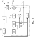
- FIG. 4 the figure illustrates an embodiment of the observer system 78 including an Extended Kalman Filter (EKF) system 90.
- the "extended" portion of the EKF system 90 may be more suitable for analyzing nonlinear data, unlike traditional Kalman filter techniques.
- the observer system 78 may monitor and estimate the operation of the engine system 8.
- the observer system 78 may estimate and monitor gas concentrations at one or more manifold sections 40, 44, 50, 51, 52, 58, 62, and/or 64, as well as pressures, temperatures, and/or mass flows at the manifold sections 40, 44, 50, 51, 52, 58, 62, and/or 64.
- engine system 8 receives suitable oxidant 32 and fuel 34, which it then mixes and combusts to achieve a desired air to fuel (AFR) ratio.
- AFR ratio may provide for a stoichiometric combustion, e.g., combustion that results in just enough oxidant 32 to substantially burn all of the fuel 34.
- Other applications may keep the AFR in a range between rich (i.e., excess fuel 34) and lean (i.e., excess oxidant 32).
- the compressor bypass valve 60 may be modulated, for example, to recirculate the pre-mixed air-fuel upstream of the compressor 42, such as from sections 42 and/or 46 into sections 40 shown in FIG. 2 .
- output signals y representative of sensors 23 as well as other sensors may be processed by an A/D converter 92 into values y k may be used to as one input or feedback to the EKF system 90.
- y [ p 2 s , P e , ⁇ e ] T
- p 2s is representative of pressure in manifold section 50 (e..g, inlet manifold)
- P e is representative of a electric power produced by an electric generator (e.g., load 24) that is mechanically coupled to the engine 10 and used to provide the electric power during engine system 8 operations
- ⁇ e is correlative to engine 10 speed
- T is time.
- y k may be summed while an output of observation h block 94 (e.g., output of h ( X ⁇ k
- X ⁇ may represent an estimated value (e.g., gas concentration, temperature, mass flow, pressure) arrived at via the models 74.
- the value K may then be summed with an output of an f d block 98 (e.g., f d ( X ⁇ k- 1
- u k may also be used as input to a block 102 (e.g., z -1 ) which may provide its output to block 98.
- u k may be representative of engine system 8 inputs (e.g. control inputs), such as fuel flow, air flow, desired gas concentration, desired engine speed, and so on. Accordingly, u k may be converted into analog signals via D/A converter 104 and used to control the engine system 8.
- u [ W gas ,u TV ,u BP ,ZZP ] T
- W gas is desired gas flow
- u TV and u BP are representative of control inputs to the TV valve 48 and CBV valve 60, respectively
- ZZP is representative of a spark ignition timing point (in crank angle degrees before top dead center (TDC) of the engine system 8.
- the observer system 78 may derive a variety of states at time T that may include predicted gas concentrations, pressures, and speeds, as desired.
- AFR s is the stoichiometricAFR of the combustions processing occurring during engine system 8 operations.
- the techniques described herein may more accurately estimate changes in the engine system 8, for example due to CBV valve 60 modulation, GM valve 30 modulation, GDV valve 38 modulation, and/or TV valve 48 modulation, among others.
- gas concentration may be more easily controlled by predicting lambda ⁇ , thus achieving a more accurate stoichiometric combustion, lean combustion, and/or rich combustion.
- the techniques described herein may provide for enhanced reliability by providing a virtual lambda sensor that may be used to confirm data received from a physical lambda sensor and/or to add a second data stream to the data received via physical sensor(s) 23.
- multistage turbocharged engine e.g., low pressure and high pressure stages
- engines having the gas 34 delivered and mixed downstream of the turbocharger 36 including single stage and multistage turbocharged engines, may be modeled and controlled.
- the techniques described herein may provide for a modeling process suitable for creating one or more manifold models that may be used to derive gas concentrations, pressures, temperature, and/or mass flows. The models may be applied to more accurately control engine systems.
- the techniques described herein may additionally provide for an Extended Kalman Filter (EKF) observer system that may predict certain engine system states (e.g., oxygen concentrations, pressure, temperatures, mass flows) and that may be used to derive the virtual lambda sensor.
- EKF Extended Kalman Filter
Landscapes
- Engineering & Computer Science (AREA)
- Chemical & Material Sciences (AREA)
- Combustion & Propulsion (AREA)
- Mechanical Engineering (AREA)
- General Engineering & Computer Science (AREA)
- Analytical Chemistry (AREA)
- Power Engineering (AREA)
- Physics & Mathematics (AREA)
- Fluid Mechanics (AREA)
- Combined Controls Of Internal Combustion Engines (AREA)
- Electrical Control Of Air Or Fuel Supplied To Internal-Combustion Engine (AREA)
Description
- The subject matter disclosed herein relates to gas combustion engines, and more specifically, to lambda or oxygen virtual sensor systems and method applied to gas combustion engines.
- Internal combustion engines known by the state of the art are disclosed by
WO 2014/154312 A1 ,EP 2 824 304 A1EP 1 158 149 A1 ,EP 1 878 900 A2WO 2009/040058 A1 ,EP 2 650 516 A1US 2015/068505 A1 . - Combustion engines will typically combust a carbonaceous fuel, such as natural gas, gasoline, diesel, and the like, and use the corresponding expansion of high temperature and pressure gases to apply a force to certain components of the engine, e.g., piston, to move the components over a distance. Accordingly, the carbonaceous fuel is transformed into mechanical motion, useful in driving a load. The load may be a generator that produces electric power. The engine may use an oxidizer, e.g., air, to mix with the carbonaceous fuel for the combustion process. The oxidizer-fuel mix may traverse a manifold to be combusted inside a combustor. It would be beneficial to improve measurement of the oxidizer-fuel mix.
- Certain embodiments commensurate in scope with the originally claimed invention are summarized below. These embodiments are not intended to limit the scope of the claimed invention, but rather these embodiments are intended only to provide a brief summary of possible forms of the invention. Indeed, the invention may encompass a variety of forms that may be similar to or different from the embodiments set forth below.
- In a first embodiment, a method includes receiving, via a first sensor, a signal representative of at least one of a manifold pressure, a manifold temperature, or a manifold mass flow rate of a manifold. The method further includes deriving, via a manifold model using a differential equation system and the first sensor signal, a derived gas concentration measurement at a first manifold section of the manifold. The method additionally includes applying the derived gas concentration measurement during operations of an engine, wherein the manifold is fluidly coupled to the engine.
- In a second embodiment, a system includes an engine control system comprising a processor configured to receive, via a first sensor, a signal representative of at least one of a manifold pressure, a manifold temperature, or a manifold mass flow rate of a manifold. The processor is further configured to derive, via a manifold model using a differential equation system and the first sensor signal, a derived gas concentration measurement at a first manifold section of the manifold. The processor is additionally configured to apply the derived gas concentration measurement during operations of an engine, wherein the manifold is fluidly coupled to the engine.
- In a third embodiment, a tangible, non-transitory computer readable medium includes code configured to receive, via a first sensor, a signal representative of at least one of a manifold pressure, a manifold temperature, or a manifold mass flow rate of a manifold. The code is further configured to derive, via a manifold model using a differential equation system and the first sensor signal, a derived gas concentration measurement at a first manifold section of the manifold. The code is additionally configured to apply the derived gas concentration measurement during operations of an engine, wherein the manifold is fluidly coupled to the engine.
- These and other features, aspects, and advantages of the present invention will become better understood when the following detailed description is read with reference to the accompanying drawings in which like characters represent like parts throughout the drawings, wherein:
-
FIG. 1 is a block diagram of an embodiment of a power production system including an internal combustion engine; -
FIG. 2 is a block diagram of an embodiment of the internal combustion engine ofFIG. 1 , including a compressor bypass flow; -
FIG. 3 is a flowchart of an embodiment of a process suitable for creating one or more manifold models for the internal combustion engine ofFIG. 2 ; and -
FIG. 4 is a block diagram of an embodiment of an observer system suitable for observing and controlling aspects of the engine show inFIGS. 1 and2 . - One or more specific embodiments of the present invention will be described below. In an effort to provide a concise description of these embodiments, all features of an actual implementation may not be described in the specification. It should be appreciated that in the development of any such actual implementation, as in any engineering or design project, numerous implementation-specific decisions must be made to achieve the developers' specific goals, such as compliance with system-related and business-related constraints, which may vary from one implementation to another. Moreover, it should be appreciated that such a development effort might be complex and time consuming, but would nevertheless be a routine undertaking of design, fabrication, and manufacture for those of ordinary skill having the benefit of this disclosure.
- When introducing elements of various embodiments of the present invention, the articles "a," "an," "the," and "said" are intended to mean that there are one or more of the elements. The terms "comprising," "including," and "having" are intended to be inclusive and mean that there may be additional elements other than the listed elements.
- The techniques described herein include the creation and use of a fluid (e.g., gas) concentration model that may predict engine inlet conditions for a variety of combustion engines, including pre-mixed multi-staged turbocharged gas engines that may be equipped with a mixture recirculation valve (e.g., compressor bypass valve). The model may use non-invasive measurements along a charging path, e.g., pressure measurements, temperature measurements, turbocharger speed and gas mass flow, to estimate a gas concentration in manifolds. In particular, the model may account for changes in gas concentration in manifolds having gas recirculation, e.g., compressor bypass, and may derive a time-dependant expression for the gas propagation along the manifolds.
- Advantageously, the model need not use measurements during or after combustion to derive the gas propagation metrics. Indeed, the model may provide for a virtual lambda sensor, e.g., oxygen proportion sensor, that may be used in lieu of or additional to a physical lambda sensor. The virtual lambda sensor may be useful for fault tolerant engine controllers, enabling the control of the engine even in circumstances where the physical lambda sensor is not working as desired. The virtual lambda sensor may additionally improve simulation of power systems that include a simulated combustion engine subsystem.
- In one embodiment, a system may include an "observer" system based on a Kalman filter that may provide for a recursive computable solution to estimate the state of the oxidizer-fuel mix, for example, the state of the oxidizer-fuel mix at the inlet of a combustion chamber. The observer system may also be used to enhance control of engine systems, for example, by providing for control decisions based on the predicted oxygen concentrations that may improve engine performance.
- Turning to the drawings,
FIG. 1 illustrates a block diagram of an embodiment of a portion of an engine drivenpower generation system 8. As described in detail below, thesystem 8 includes an engine 10 (e.g., a reciprocating internal combustion engine) having one or more combustion chambers 12 (e.g., 1, 2, 3, 4, 5, 6, 7, 8, 10, 12, 14, 16, 18, 20, or more combustion chambers 12). Anair supply 14 is configured to provide a pressurizedoxidant 16, such as air, oxygen, oxygen-enriched air, oxygen-reduced air, or any combination thereof, to eachcombustion chamber 12. Thecombustion chamber 12 is also configured to receive a fuel 18 (e.g., a liquid and/or gaseous fuel) from afuel supply 19, and a fuel-air mixture ignites and combusts within eachcombustion chamber 12. The hot pressurized combustion gases cause apiston 20 adjacent to eachcombustion chamber 12 to move linearly within acylinder 26 and convert pressure exerted by the gases into a rotating motion, which causes ashaft 22 to rotate. Further, theshaft 22 may be coupled to aload 24, which is powered via rotation of theshaft 22. For example, theload 24 may be any suitable device that may generate power via the rotational output of thesystem 10, such as an electrical generator. Additionally, although the following discussion refers to air as theoxidant 16, any suitable oxidant may be used with the disclosed embodiments. Similarly, thefuel 18 may be any suitable gaseous fuel, such as natural gas, associated petroleum gas, propane, biogas, sewage gas, landfill gas, coal mine gas, for example. - The
system 8 disclosed herein may be adapted for use in stationary applications (e.g., in industrial power generating engines) or in mobile applications (e.g., in cars or aircraft). Theengine 10 may be a two-stroke engine, three-stroke engine, four-stroke engine, five-stroke engine, or six-stroke engine. Theengine 10 may also include any number ofcombustion chambers 12,pistons 20, and associated cylinders (e.g., 1-24). For example, in certain embodiments, thesystem 8 may include a large-scale industrial reciprocating engine having 4, 6, 8, 10, 16, 24 ormore pistons 20 reciprocating in cylinders. In some such cases, the cylinders and/or thepistons 20 may have a diameter of between approximately 13.5 - 34 centimeters (cm). In some embodiments, the cylinders and/or thepistons 20 may have a diameter of between approximately 10-40 cm, 15-25 cm, or about 15 cm. Thesystem 10 may generate power ranging from 10 kW to 10 MW. In some embodiments, theengine 10 may operate at less than approximately 1800 revolutions per minute (RPM). In some embodiments, theengine 10 may operate at less than approximately 2000 RPM, 1900 RPM, 1700 RPM, 1600 RPM, 1500 RPM, 1400 RPM, 1300 RPM, 1200 RPM, 1000 RPM, 900 RPM, or 750 RPM. In some embodiments, theengine 10 may operate between approximately 750-2000 RPM, 900-1800 RPM, or 1000-1600 RPM. In some embodiments, theengine 10 may operate at approximately 1800 RPM, 1500 RPM, 1200 RPM, 1000 RPM, or 900 RPM.Exemplary engines 10 may include General Electric Company's Jenbacher Engines (e.g., Jenbacher Type 2, Type 3, Type 4, Type 6 or J920 FleXtra) or Waukesha Engines (e.g., Waukesha VGF, VHP, APG, 275GL), for example. Additionally or alternatively, one or morephysical sensors 23 may be disposed at various locations of theengine system 8, such as in manifolds, exhaust ducts, and the like.Other sensors 23 may include pressure sensors, temperature sensors, mass flow sensors, and/or sensors measuring species concentrations (e.g., oxygen concentrations), which may be disposed at locations including manifolds, exhaust ducts, fuel and air delivery conduits, and the like. Thesensors 23 may include lambda sensors, oxygen ratio sensors, oxygen percentage sensors, or a combination thereof. Various embodiments of theengine system 8 may be analyzed to derive certain properties, such as gas concentrations, pressures, flows (e.g., mass flows), temperatures, speed, and so on, using the techniques described herein. For example,FIG. 2 shows an embodiment of theengine system 8 that includes a pre-combustion compressor and an exhaust driven turbine. - More specifically,
FIG. 2 is a block diagram of an embodiment of thegas engine 10 including agas mixer 30 that mayintake air 32 andfuel gas 34 to produce a pre-mixed fuel. In the depicted embodiment, theengine system 8 includes a single stage turbocharged engine, e.g.,engine 10 that is turbocharged viaturbocharger system 36. Agas dosage valve 38 is also shown, used to deliver thegas fuel 34 into thegas mixer 30, to be mixed with theair 32. After thegas mixer 30, the pre-mixed fuel may travel through amanifold section 40 to a radial compressor 42 to be compressed, thus improving fuel burn. The compressed, pre-mixed fuel may have increased temperature during compression, and the compressed pre-mixed fuel may then travel through amanifold section 44 to anintercooler 46. Theintercooler 46 may reduce the compressed pre-mixed fuel's temperature, improving energy efficiency. Athrottle valve 48 may be used to provide the compressed premixed fuel to be combusted incylinders 26 of theengine 10, which may then result in mechanical movement of thepistons 20. In the depicted embodiment, thethrottle valve 48 is downstream of amanifold section 50, and upstream of amanifold section 51.Manifold sections 50 terminate atinlets 53. By modulating or driving thethrottle valve 48 theECU 25 may increase or decrease fuel flow into thecylinders 26 throughmanifold sections 50, thus increasing or decreasing engine speed (e.g., revolutions per minute [RPM], torque, and so on). TheECU 25 may include one ormore processors 27 suitable for executing computer code or instructions, and amemory 29. Thememory 29 may store the computer code or instructions as well as certain models and processes described in more detail below. - After combustion, exhaust may flow through
exhaust manifold section 52 into aturbine 54, with enthalpy of the exhaust further used to provide rotative power to theturbine 54. The compressor 42 is mechanically coupled to theturbine 54 via ashaft 56, thus resulting in the turbocharger 36 (e.g., compressor 42,turbine 54, shaft 56) being suitable for using exhaust to compress the pre-mixed air-fuel mixture. The exhaust may then exitmanifold section 58 for further processing, such as processing via a catalytic converter, to then be released to ambient. - Also depicted are a
compressor bypass valve 60 disposed onbypass manifold sections valve 60 may prevent undesired conditions, such as compressor 42 surge, by recirculating the pre-mixed air-fuel upstream of the compressor 42, such as from sections 42 and/or 46 intosections 40. The techniques described herein enable the creation of a virtual lambda sensor suitable for deriving, for example, gas as a percentage of the overall air-fuel mix, pressures (e.g., pressures p1, p2, p3, pem, p4), temperatures (e.g., temperatures T1, T2, Tem, T4), mass flows, and the like, at various points through the manifold sections shown, such assections sections sections - As shown in flowchart form in
FIG. 3 , aprocess 70 may be used to derive a model suitable for deriving gas concentration and other properties (e.g., pressures, temperatures, mass flows) of themanifold sections process 70 may be implemented as computer executable code or instructions that may be stored in a memory (e.g., memory 29) of a computing device, such as theECU 25, and may be executed by theprocessor 27. Theprocess 70 may additionally or alternatively be stored and executed by a computing device such as a workstation, personal computer, server, mobile device, tablet, or a combination thereof. In the depicted embodiment, theprocess 70 may analyze (block 72) an engine system, such as theengine system 8 shown inFIG. 2 . The analysis (block 72) may include a manifold modeling useful in capturing at least 1) a transport effect from thegas mixer 30 to theengine inlets 53 and 2) the effect of gas propagation through themanifolds sections gas mixer 30 to theinlets 53 is given by flow speed, which varies with theengine 10 load. The time delay on a transfer function introduces a phase lag that grows linearly with the frequency and is proportional to its magnitude. For a time delay t, a frequency phase plot is shifted by wt radians. The larger the magnitude of the time delay t, the smaller the stability margins. - The gas propagation through the
manifold sections engine inlets 53 to the compressor 42 inlet. The gas concentration at the compressor 42 inlet results from the mixture flow originated atgas mixer 30 and the recirculating flow thought thecompressor bypass valve 60. Thecompressor bypass 60 mass flow may thus act as a damper with a damping ratio □. At high flow speeds, the magnitude of □ <1 while at low flow speeds, □ >1. The variation of the damping ratio □ over the load results on a transition from complex poles to real poles as the load increases. Due to the high coupling gain between thecompressor bypass 60,throttle valve 48 andgas dosage 38, this gain effect leads to a limit cycle during transient operation as the system poles move towards a stability limit axis as □ grows. Model(s) 74 may then be developed to account for gas transport and to develop control strategies forgas dosage 34 andturbocharger 36 control. - From the ideal gas law (e.g., PV= nRT, where P is pressure, V is volume, n is an amount in moles, R is an ideal gas constant, and T is temperature) the total pressure in the manifold sections desired to be modeled (e.g., 40, 44, 50, 51, 52, 58, 62, and/or 64) can be derived using Dalton's law for not reacting mixtures as follows:

- Given that the molecular weights of air and gas are comparable, complete mixing of gas and air in the manifold may be assumed. In that case the amount of air and gas leaving the manifold would have the same ratio as that of the mass of air and gas in the manifold at any time, thus:
The manifold dynamics may include a filling emptying dynamics that may govern the pressure in the manifold. The total manifold pressure is used as state variable in an air-path model. This state variable can be accurately measured. The gas fraction relates the gas mass to the total mass in the manifold. - The gas fraction rate is given as function of the gas and total inlet gas flows and the air molar mass.

- The total pressure in the manifolds can be expressed as follows:

- Equations (2) and (3) constitute a differential equation system suitable for deriving the manifold pressure and gas fraction, which may be used as one or more of the model(s) 74.
- Since the gas and air temperature flowing in the manifold may differ, the previous differential equation system may be extended by including a quasi-static temperature gradient as a function of the mass flows. This form can be developed balancing the heat flow in the manifold including the wall transfer (e.g., wall of the
manifold sections 
- Extending the number of inputs a and outputs b the manifold dynamics for gas fraction and total pressure can be expressed as follows:


- The differential equation system (33) reveals that when making the gas fraction equal zero, the differential system equation can be simplified for the case of air charged engines.


- As shown, any of the equations (1)-(9) may be included in the one or
more models 74, for example, to derive desired quantities, e.g., pressure, temperature, mass flow, and/or oxygen concentration c at one or more of the manifold sections. Indeed, by executing the model(s) 74, a virtual gas concentration sensor may be provided, suitable for measuring gas concentrations in any one or more of themanifold sections - The
process 70 may additionally or alternatively derive (block 76) an observer system, such as anobserver system 78 that includes a Kalman filter. Theobserver system 78 may be implemented in hardware or in software. In a software example, theobserver system 78 may be stored in thememory 29 and executed by the processor(s) 27. In one example, theobserver system 78 may observe physical measurement obtained via the sensor(s) 23 and use the model(s) 74 to adjust the observation during engine control. Indeed, theobserver system 78 may more optimally estimate or infer parameters of interest (e.g., gas concentrations, pressure, temperature, mass flow) from observations of the sensors(s) 23 and/or from derivations provided by themodels 74, and then derive future states of theengine system 8. The derived future states may then be used, for example, to more efficiently and accurately monitor and/or control (block 80) operations of theengine system 8. - Turning now to
FIG. 4 , the figure illustrates an embodiment of theobserver system 78 including an Extended Kalman Filter (EKF) system 90. The "extended" portion of the EKF system 90 may be more suitable for analyzing nonlinear data, unlike traditional Kalman filter techniques. Theobserver system 78 may monitor and estimate the operation of theengine system 8. In particular, theobserver system 78 may estimate and monitor gas concentrations at one or moremanifold sections manifold sections engine system 8 receivessuitable oxidant 32 andfuel 34, which it then mixes and combusts to achieve a desired air to fuel (AFR) ratio. Depending on theengine system 8 mode or operation or embodiment, the AFR ratio may provide for a stoichiometric combustion, e.g., combustion that results in justenough oxidant 32 to substantially burn all of thefuel 34. Other applications may keep the AFR in a range between rich (i.e., excess fuel 34) and lean (i.e., excess oxidant 32). During operations, thecompressor bypass valve 60 may be modulated, for example, to recirculate the pre-mixed air-fuel upstream of the compressor 42, such as from sections 42 and/or 46 intosections 40 shown inFIG. 2 . - It would be beneficial to predict future and/or current states or conditions of the
engine system 8 based on the fluid flows throughmanifold sections sensors 23 as well as other sensors (e.g., fuel delivery sensors, air delivery sensors, pressure sensors, temperature sensors, engine speed sensors, engine torque sensors) may be processed by an A/D converter 92 into values yk may be used to as one input or feedback to the EKF system 90. In one embodiment, y = [p 2s , Pe , ωe ] T, where p2s is representative of pressure in manifold section 50 (e..g, inlet manifold), Pe is representative of a electric power produced by an electric generator (e.g., load 24) that is mechanically coupled to theengine 10 and used to provide the electric power duringengine system 8 operations, ωe is correlative toengine 10 speed, and T is time. - In the depicted example, yk may be summed while an output of observation h block 94 (e.g., output of h(X̂ k|k-1, uk ) ) may be subtracted to arrive at a value K (shown via element number 96), e.g., optimal Kalman gain with updates. X̂ may represent an estimated value (e.g., gas concentration, temperature, mass flow, pressure) arrived at via the
models 74. The value K may then be summed with an output of an fd block 98 (e.g., fd (X̂ k-1|k-1, u k-1) ), the sum which may then be used an input to block 100 (e.g., z-1, representative of the square root of an observation of the true state), as well as to theblock 94. uk may also be used as input to a block 102 (e.g., z-1) which may provide its output to block 98. uk may be representative ofengine system 8 inputs (e.g. control inputs), such as fuel flow, air flow, desired gas concentration, desired engine speed, and so on. Accordingly, uk may be converted into analog signals via D/A converter 104 and used to control theengine system 8. - In one embodiment, u = [Wgas,uTV,uBP,ZZP] T, where Wgas is desired gas flow, uTV and uBP are representative of control inputs to the
TV valve 48 andCBV valve 60, respectively, and ZZP is representative of a spark ignition timing point (in crank angle degrees before top dead center (TDC) of theengine system 8. - In one embodiment, the
observer system 78 may derive x estimated states for thesingle stage turbocharger 36 embodiment ofFIG. 2 , x = [c g1, p 2, c g2 , p 2 s, c g2s , p 3, ωTC, ωe ] T , where c g1 may be representative of gas concentration at, e.g.,manifold section 40, p 2 may be representative of pressure at, e.g.,manifold section 51, c g2 may be representative of gas concentration at, e.g.,manifold section 51, p 2s may be representative of pressure at, e.g., manifold section 50 (e.g., inlet manifold), c g2s may be representative of gas concentration at, e.g., manifold section 50 (e.g., inlet manifold), p 3 may be representative of pressure at, e.g.,manifold section 52, ωTC may be representative ofturbocharger 36 speed, and ωe may be representative ofengine 10 speed. Indeed, theobserver system 78 may derive a variety of states at time T that may include predicted gas concentrations, pressures, and speeds, as desired. In one embodiment, theobserver system 78 may also be used to provide a virtual lambda sensor suitable for deriving a lambda λ:

- AFRs is the stoichiometricAFR of the combustions processing occurring during
engine system 8 operations. By recursively samplingsensor 23 data and applying model(s) 74 to derive predict and derive estimates states x, the techniques described herein may more accurately estimate changes in theengine system 8, for example due toCBV valve 60 modulation,GM valve 30 modulation,GDV valve 38 modulation, and/orTV valve 48 modulation, among others. For example, gas concentration may be more easily controlled by predicting lambda λ, thus achieving a more accurate stoichiometric combustion, lean combustion, and/or rich combustion. Additionally or alternatively, the techniques described herein may provide for enhanced reliability by providing a virtual lambda sensor that may be used to confirm data received from a physical lambda sensor and/or to add a second data stream to the data received via physical sensor(s) 23. - It is to be noted that while the techniques presented herein are described in view of a single stage turbocharged engine, the techniques described herein may be applied to model and control other engine types. For example, multistage turbocharged engine (e.g., low pressure and high pressure stages) may be similarly modeled and controlled. Likewise, engines having the
gas 34 delivered and mixed downstream of theturbocharger 36, including single stage and multistage turbocharged engines, may be modeled and controlled. - Technical effects of the invention include providing for a virtual lambda sensor that may aid in more accurately controlling a variety of engines including compressor recirculation. The techniques described herein may provide for a modeling process suitable for creating one or more manifold models that may be used to derive gas concentrations, pressures, temperature, and/or mass flows. The models may be applied to more accurately control engine systems. The techniques described herein may additionally provide for an Extended Kalman Filter (EKF) observer system that may predict certain engine system states (e.g., oxygen concentrations, pressure, temperatures, mass flows) and that may be used to derive the virtual lambda sensor.
- This written description uses examples to disclose the invention, including the best mode, and also to enable any person skilled in the art to practice the invention, including making and using any devices or systems and performing any incorporated methods. The patentable scope of the invention is defined by the claims, and may include other examples that occur to those skilled in the art. Such other examples are intended to be within the scope of the claims if they have structural elements that do not differ from the literal language of the claims.
Claims (15)
- A method, comprising:receiving, via a first sensor (23), a signal representative of at least one of a manifold pressure, a manifold temperature, or a manifold mass flow rate of a manifold;deriving, via a manifold model (74) using a differential equation system and the first sensor signal, a derived gas concentration measurement at a first manifold section of the manifold (40, 44, 50, 51, 52, 58, 62, 64); andapplying the derived gas concentration measurement during operations of a gas engine (10), wherein the manifold (40, 44, 50, 51, 52, 58, 62, 64) is fluidly coupled to the gas engine (10).
- The method of claim 1, wherein the manifold model (74) comprises a physics-based mass flow model accounting for a compressor bypass recirculating flow through the manifold (40, 44, 50, 51, 52, 58, 62, 64).
- The method of claim 2, wherein the manifold (40, 44, 50, 51, 52, 58, 62, 64) comprises a charging manifold fluidly coupled to an inlet (53) of the gas engine (10) and configured to provide fuel and an oxidant to the inlet (53).
- The method of claim 1, wherein the derived gas concentration measurement comprises a lambda measurement.
- The method of claim 4, wherein the lambda measurement comprises a

- The method of claim 1, wherein deriving, via the manifold model (74), the derived gas concentration measurement, comprises executing a Kalman filter to derive one or more estimated states.
- A system (8) having a gas engine (10), a first manifold section of a manifold (40, 44, 50, 51, 52, 58, 62, 64) and a first sensor (23), further comprising
An engine control system (8) comprising a processor (27) configured to:receive, via the first sensor (23), a signal representative of at least one of a manifold pressure, a manifold temperature, or a manifold mass flow rate of a manifold;derive, via a manifold model (74) using a differential equation system and the first sensor (23) signal, a derived gas concentration measurement at the first manifold section of the manifold (40, 44, 50, 51, 52, 58, 62, 64); andapply the derived gas concentration measurement during operations of the gas engine (10), wherein the manifold (40, 44, 50, 51, 52, 58, 62, 64) is fluidly coupled to the gas engine (10). - The system of claim 7, wherein the manifold model comprises a physics-based mass flow model accounting for a compressor bypass recirculating flow through the manifold (40, 44, 50, 51, 52, 58, 62, 64), and wherein the manifold (40, 44, 50, 51, 52, 58, 62, 64) comprises a charging manifold (40, 44, 50, 51, 52, 58, 62, 64) fluidly coupled to an inlet (53) of the gas engine (10) and configured to provide fuel and an oxidant to the inlet (53).
- The system of claim 7, wherein the derived gas concentration measurement comprises a lambda measurement

- The system of claim 7, wherein the processor (27) is configured to execute a Kalman filter to derive one or more estimated states when deriving, via the manifold model (74), the derived gas concentration measurement, and wherein the one or more estimated states are applied for controlling the gas engine (10).
- A computer program product comprising instructions, which when the program is executed by the processor (27) of the system (8) of claim 7, cause the processor (27) to carry out the following:receive, via a first sensor (23), a signal representative of at least one of a manifold pressure, a manifold temperature, or a manifold mass flow rate of a manifold;derive, via a manifold model (74) a differential equation system and the first sensor signal, a derived gas concentration measurement at a first manifold section of the manifold (40, 44, 50, 51, 52, 58, 62, 64); andapply the derived gas concentration measurement during operations of a gas engine (10), wherein the manifold (40, 44, 50, 51, 52, 58, 62, 64) is fluidly coupled to the gas engine (10).
- The computer program product of claim 11, wherein the derived gas concentration measurement comprises a lambda measurement.
- The computer program product of claim 11, wherein the code configured to derive, via the manifold model (74), the derived gas concentration measurement, comprises code configured to execute a Kalman filter to derive one or more estimated states.
- The computer program product of claim 13, comprising code configured to recursively apply an engine output y to derive the one or more estimated states, wherein the engine output y comprises at least one of an intake manifold pressure, an engine speed, a generator electrical power, or a combination thereof, and wherein the gas engine (10) is mechanically coupled to an electrical generator to produce the generator electrical power during operations.
- The computer program product of claim 13, wherein the Kalman filter is configured to derive a control input u, and wherein applying the derived gas concentration measurement during operations of a gas engine (10) comprises applying the control input u, to control the gas engine (10) during operations.
Applications Claiming Priority (2)
| Application Number | Priority Date | Filing Date | Title |
|---|---|---|---|
| US14/823,806 US9719445B2 (en) | 2015-08-11 | 2015-08-11 | Lambda virtual sensor systems and methods for a combustion engine |
| PCT/US2016/040929 WO2017027121A1 (en) | 2015-08-11 | 2016-07-05 | Lambda virtual sensor systems and methods for a combustion engine |
Publications (2)
| Publication Number | Publication Date |
|---|---|
| EP3334917A1 EP3334917A1 (en) | 2018-06-20 |
| EP3334917B1 true EP3334917B1 (en) | 2024-08-28 |
Family
ID=56567672
Family Applications (1)
| Application Number | Title | Priority Date | Filing Date |
|---|---|---|---|
| EP16747652.2A Active EP3334917B1 (en) | 2015-08-11 | 2016-07-05 | Lambda virtual sensor systems and methods for a combustion engine |
Country Status (4)
| Country | Link |
|---|---|
| US (1) | US9719445B2 (en) |
| EP (1) | EP3334917B1 (en) |
| CA (1) | CA2994531C (en) |
| WO (1) | WO2017027121A1 (en) |
Citations (7)
| Publication number | Priority date | Publication date | Assignee | Title |
|---|---|---|---|---|
| EP1158149A1 (en) * | 2000-05-26 | 2001-11-28 | Jenbacher Aktiengesellschaft | Device for air/fuel ratio estimation in a gas engine |
| EP1878900A2 (en) * | 2006-07-13 | 2008-01-16 | GE Jenbacher GmbH & Co. OHG | Method for diagnosing erroneous operating states of an internal combustion engine |
| WO2009040058A1 (en) * | 2007-09-21 | 2009-04-02 | Mtu Friedrichshafen Gmbh | Method for controlling a stationary gas motor |
| EP2650516A1 (en) * | 2012-04-11 | 2013-10-16 | Peugeot Citroën Automobiles Sa | Method for estimating the fuel-to-air ratio in an internal combustion engine of a motor vehicle |
| WO2014154312A1 (en) * | 2013-03-28 | 2014-10-02 | Mtu Friedrichshafen Gmbh | Method and device for operating an internal combustion engine |
| EP2824304A1 (en) * | 2013-05-10 | 2015-01-14 | General Electric Company | Gas dosage control for gas turbine engine |
| US20150068505A1 (en) * | 2013-09-09 | 2015-03-12 | Denso Corporation | Cylinder-by-cylinder air-fuel-ratio controller for internal combustion engine |
Family Cites Families (5)
| Publication number | Priority date | Publication date | Assignee | Title |
|---|---|---|---|---|
| EP0156371B1 (en) * | 1984-03-28 | 1990-05-30 | Hitachi, Ltd. | Fuel dispenser for internal combustion engine |
| DE102009033082B3 (en) | 2009-07-03 | 2011-01-13 | Mtu Friedrichshafen Gmbh | Method for controlling a gas engine |
| US8267069B2 (en) * | 2009-08-25 | 2012-09-18 | International Engine Intellectual Property Company, Llc | EMG temp signal model based on EGRC out temp for EGR system anti-fouling protection |
| US8985088B2 (en) * | 2012-07-31 | 2015-03-24 | General Electric Company | Systems and methods for controlling exhaust gas recirculation |
| US9611794B2 (en) * | 2012-07-31 | 2017-04-04 | General Electric Company | Systems and methods for controlling exhaust gas recirculation |
-
2015
- 2015-08-11 US US14/823,806 patent/US9719445B2/en active Active
-
2016
- 2016-07-05 WO PCT/US2016/040929 patent/WO2017027121A1/en not_active Ceased
- 2016-07-05 CA CA2994531A patent/CA2994531C/en active Active
- 2016-07-05 EP EP16747652.2A patent/EP3334917B1/en active Active
Patent Citations (9)
| Publication number | Priority date | Publication date | Assignee | Title |
|---|---|---|---|---|
| EP1158149A1 (en) * | 2000-05-26 | 2001-11-28 | Jenbacher Aktiengesellschaft | Device for air/fuel ratio estimation in a gas engine |
| EP1878900A2 (en) * | 2006-07-13 | 2008-01-16 | GE Jenbacher GmbH & Co. OHG | Method for diagnosing erroneous operating states of an internal combustion engine |
| WO2009040058A1 (en) * | 2007-09-21 | 2009-04-02 | Mtu Friedrichshafen Gmbh | Method for controlling a stationary gas motor |
| US20100256890A1 (en) * | 2007-09-21 | 2010-10-07 | Mtu Friedrichshafen, Gmbh | Method for Controlling a Stationary Gas Motor |
| EP2650516A1 (en) * | 2012-04-11 | 2013-10-16 | Peugeot Citroën Automobiles Sa | Method for estimating the fuel-to-air ratio in an internal combustion engine of a motor vehicle |
| WO2014154312A1 (en) * | 2013-03-28 | 2014-10-02 | Mtu Friedrichshafen Gmbh | Method and device for operating an internal combustion engine |
| US20160040611A1 (en) * | 2013-03-28 | 2016-02-11 | Mtu Friedrichshafen Gmbh | Method and device for operating an internal combustion engine |
| EP2824304A1 (en) * | 2013-05-10 | 2015-01-14 | General Electric Company | Gas dosage control for gas turbine engine |
| US20150068505A1 (en) * | 2013-09-09 | 2015-03-12 | Denso Corporation | Cylinder-by-cylinder air-fuel-ratio controller for internal combustion engine |
Also Published As
| Publication number | Publication date |
|---|---|
| US20170045010A1 (en) | 2017-02-16 |
| WO2017027121A1 (en) | 2017-02-16 |
| US9719445B2 (en) | 2017-08-01 |
| CA2994531A1 (en) | 2017-02-16 |
| CA2994531C (en) | 2023-09-26 |
| EP3334917A1 (en) | 2018-06-20 |
Similar Documents
| Publication | Publication Date | Title |
|---|---|---|
| Niki et al. | Diesel fuel multiple injection effects on emission characteristics of diesel engine mixed ammonia gas into intake air | |
| Akbari et al. | A review of wave rotor technology and its applications | |
| Killingsworth et al. | A simple HCCI engine model for control | |
| Ipci et al. | Thermodynamic and dynamic modeling of a single cylinder four stroke diesel engine | |
| Wang et al. | Study of fuel-controlled aircraft engine for fuel-powered unmanned aerial vehicle: Energy conversion analysis and optimization | |
| Divekar et al. | Study of cylinder charge control for enabling low temperature combustion in diesel engines | |
| US9719445B2 (en) | Lambda virtual sensor systems and methods for a combustion engine | |
| Desai | Computer aided kinematic and dynamic analysis of a horizontal slider crank mechanism used for single-cylinder four stroke internal combustion engine | |
| Akbari et al. | Two-Stage wave disk engine concept and performance prediction | |
| Douvartzides et al. | Thermodynamic Cycle Analysis of an Automotive Internal Combustion Engine With the Characteristics of the Commercial BMW N54 Spark-Ignition Model | |
| Ahammed | Hydrogen-Argon Power Cycle (HAPC) on a Wartsila medium-speed engine: an Investigation using 1D-Simulation. | |
| Johansson et al. | Modelling a hydrogen fuelled composite cycle aeroengine | |
| Ausserer et al. | Engine-Control Impact on Energy Balances for Two-Stroke Engines for 10–25 kg Remotely Piloted Aircraft | |
| Jelić et al. | Analysis of internal combustion engine thermodynamic using the second law of thermodynamics | |
| Yu et al. | Research on Modelling of Aviation Piston Engine for the Hardware-in-the-loop Simulation | |
| Reinhart et al. | Experimental Observations of a Small-Scale Pressure Wave Supercharger Coupled to a Compression Ignition Engine | |
| Glenn | Coordinated control of the turbo electrically assisted variable geometry turbocharged diesel engine with exhaust gas recirculation | |
| Razmara et al. | Novel Exergy-Wise Predictive control of internal combustion engines | |
| Machín Arregui | Development of a Turbocharger for a Formula Sae Car Engine | |
| Douvartzides et al. | Thermal design of a natural gas-diesel dual fuel turbocharged V18 engine for ship propulsion and power plant applications | |
| Snyder et al. | Pressure Gain Combustor Component Viability Assessment Based on Initial Testing | |
| Kuzmych et al. | Robust nonlinear control design for turbocharged biodiesel engine | |
| Buchman et al. | Analyzing the Effect of Air Capacitor Turbocharging Single Cylinder Engines on Fuel Economy and Emissions Through Modeling and Experimentation | |
| Chaudhary et al. | Application of exergy analysis to internal combustion engine: a review | |
| Wang et al. | Theoretical Analyses of Heat Balance in a Diesel/Natural Gas Dual-Fuel Engine at Low and Medium Loads Based on Experimental Values |
Legal Events
| Date | Code | Title | Description |
|---|---|---|---|
| STAA | Information on the status of an ep patent application or granted ep patent |
Free format text: STATUS: THE INTERNATIONAL PUBLICATION HAS BEEN MADE |
|
| PUAI | Public reference made under article 153(3) epc to a published international application that has entered the european phase |
Free format text: ORIGINAL CODE: 0009012 |
|
| STAA | Information on the status of an ep patent application or granted ep patent |
Free format text: STATUS: REQUEST FOR EXAMINATION WAS MADE |
|
| 17P | Request for examination filed |
Effective date: 20180312 |
|
| AK | Designated contracting states |
Kind code of ref document: A1 Designated state(s): AL AT BE BG CH CY CZ DE DK EE ES FI FR GB GR HR HU IE IS IT LI LT LU LV MC MK MT NL NO PL PT RO RS SE SI SK SM TR |
|
| AX | Request for extension of the european patent |
Extension state: BA ME |
|
| DAV | Request for validation of the european patent (deleted) | ||
| DAX | Request for extension of the european patent (deleted) | ||
| RAP1 | Party data changed (applicant data changed or rights of an application transferred) |
Owner name: AI ALPINE US BIDCO INC. |
|
| STAA | Information on the status of an ep patent application or granted ep patent |
Free format text: STATUS: EXAMINATION IS IN PROGRESS |
|
| 17Q | First examination report despatched |
Effective date: 20201217 |
|
| P01 | Opt-out of the competence of the unified patent court (upc) registered |
Effective date: 20230602 |
|
| GRAP | Despatch of communication of intention to grant a patent |
Free format text: ORIGINAL CODE: EPIDOSNIGR1 |
|
| STAA | Information on the status of an ep patent application or granted ep patent |
Free format text: STATUS: GRANT OF PATENT IS INTENDED |
|
| INTG | Intention to grant announced |
Effective date: 20240517 |
|
| GRAS | Grant fee paid |
Free format text: ORIGINAL CODE: EPIDOSNIGR3 |
|
| GRAA | (expected) grant |
Free format text: ORIGINAL CODE: 0009210 |
|
| STAA | Information on the status of an ep patent application or granted ep patent |
Free format text: STATUS: THE PATENT HAS BEEN GRANTED |
|
| AK | Designated contracting states |
Kind code of ref document: B1 Designated state(s): AL AT BE BG CH CY CZ DE DK EE ES FI FR GB GR HR HU IE IS IT LI LT LU LV MC MK MT NL NO PL PT RO RS SE SI SK SM TR |
|
| REG | Reference to a national code |
Ref country code: GB Ref legal event code: FG4D |
|
| REG | Reference to a national code |
Ref country code: CH Ref legal event code: EP |
|
| REG | Reference to a national code |
Ref country code: DE Ref legal event code: R096 Ref document number: 602016089118 Country of ref document: DE |
|
| REG | Reference to a national code |
Ref country code: IE Ref legal event code: FG4D |
|
| REG | Reference to a national code |
Ref country code: LT Ref legal event code: MG9D |
|
| PG25 | Lapsed in a contracting state [announced via postgrant information from national office to epo] |
Ref country code: NO Free format text: LAPSE BECAUSE OF FAILURE TO SUBMIT A TRANSLATION OF THE DESCRIPTION OR TO PAY THE FEE WITHIN THE PRESCRIBED TIME-LIMIT Effective date: 20241128 |
|
| REG | Reference to a national code |
Ref country code: AT Ref legal event code: MK05 Ref document number: 1718176 Country of ref document: AT Kind code of ref document: T Effective date: 20240828 |
|
| PG25 | Lapsed in a contracting state [announced via postgrant information from national office to epo] |
Ref country code: FI Free format text: LAPSE BECAUSE OF FAILURE TO SUBMIT A TRANSLATION OF THE DESCRIPTION OR TO PAY THE FEE WITHIN THE PRESCRIBED TIME-LIMIT Effective date: 20240828 Ref country code: PT Free format text: LAPSE BECAUSE OF FAILURE TO SUBMIT A TRANSLATION OF THE DESCRIPTION OR TO PAY THE FEE WITHIN THE PRESCRIBED TIME-LIMIT Effective date: 20241230 Ref country code: PL Free format text: LAPSE BECAUSE OF FAILURE TO SUBMIT A TRANSLATION OF THE DESCRIPTION OR TO PAY THE FEE WITHIN THE PRESCRIBED TIME-LIMIT Effective date: 20240828 Ref country code: GR Free format text: LAPSE BECAUSE OF FAILURE TO SUBMIT A TRANSLATION OF THE DESCRIPTION OR TO PAY THE FEE WITHIN THE PRESCRIBED TIME-LIMIT Effective date: 20241129 Ref country code: NL Free format text: LAPSE BECAUSE OF FAILURE TO SUBMIT A TRANSLATION OF THE DESCRIPTION OR TO PAY THE FEE WITHIN THE PRESCRIBED TIME-LIMIT Effective date: 20240828 |
|
| PG25 | Lapsed in a contracting state [announced via postgrant information from national office to epo] |
Ref country code: BG Free format text: LAPSE BECAUSE OF FAILURE TO SUBMIT A TRANSLATION OF THE DESCRIPTION OR TO PAY THE FEE WITHIN THE PRESCRIBED TIME-LIMIT Effective date: 20240828 |
|
| PG25 | Lapsed in a contracting state [announced via postgrant information from national office to epo] |
Ref country code: LV Free format text: LAPSE BECAUSE OF FAILURE TO SUBMIT A TRANSLATION OF THE DESCRIPTION OR TO PAY THE FEE WITHIN THE PRESCRIBED TIME-LIMIT Effective date: 20240828 |
|
| REG | Reference to a national code |
Ref country code: NL Ref legal event code: MP Effective date: 20240828 |
|
| PG25 | Lapsed in a contracting state [announced via postgrant information from national office to epo] |
Ref country code: AT Free format text: LAPSE BECAUSE OF FAILURE TO SUBMIT A TRANSLATION OF THE DESCRIPTION OR TO PAY THE FEE WITHIN THE PRESCRIBED TIME-LIMIT Effective date: 20240828 Ref country code: IS Free format text: LAPSE BECAUSE OF FAILURE TO SUBMIT A TRANSLATION OF THE DESCRIPTION OR TO PAY THE FEE WITHIN THE PRESCRIBED TIME-LIMIT Effective date: 20241228 |
|
| PG25 | Lapsed in a contracting state [announced via postgrant information from national office to epo] |
Ref country code: HR Free format text: LAPSE BECAUSE OF FAILURE TO SUBMIT A TRANSLATION OF THE DESCRIPTION OR TO PAY THE FEE WITHIN THE PRESCRIBED TIME-LIMIT Effective date: 20240828 |
|
| PG25 | Lapsed in a contracting state [announced via postgrant information from national office to epo] |
Ref country code: ES Free format text: LAPSE BECAUSE OF FAILURE TO SUBMIT A TRANSLATION OF THE DESCRIPTION OR TO PAY THE FEE WITHIN THE PRESCRIBED TIME-LIMIT Effective date: 20240828 Ref country code: RS Free format text: LAPSE BECAUSE OF FAILURE TO SUBMIT A TRANSLATION OF THE DESCRIPTION OR TO PAY THE FEE WITHIN THE PRESCRIBED TIME-LIMIT Effective date: 20241128 |
|
| PG25 | Lapsed in a contracting state [announced via postgrant information from national office to epo] |
Ref country code: RS Free format text: LAPSE BECAUSE OF FAILURE TO SUBMIT A TRANSLATION OF THE DESCRIPTION OR TO PAY THE FEE WITHIN THE PRESCRIBED TIME-LIMIT Effective date: 20241128 Ref country code: PT Free format text: LAPSE BECAUSE OF FAILURE TO SUBMIT A TRANSLATION OF THE DESCRIPTION OR TO PAY THE FEE WITHIN THE PRESCRIBED TIME-LIMIT Effective date: 20241230 Ref country code: PL Free format text: LAPSE BECAUSE OF FAILURE TO SUBMIT A TRANSLATION OF THE DESCRIPTION OR TO PAY THE FEE WITHIN THE PRESCRIBED TIME-LIMIT Effective date: 20240828 Ref country code: NO Free format text: LAPSE BECAUSE OF FAILURE TO SUBMIT A TRANSLATION OF THE DESCRIPTION OR TO PAY THE FEE WITHIN THE PRESCRIBED TIME-LIMIT Effective date: 20241128 Ref country code: NL Free format text: LAPSE BECAUSE OF FAILURE TO SUBMIT A TRANSLATION OF THE DESCRIPTION OR TO PAY THE FEE WITHIN THE PRESCRIBED TIME-LIMIT Effective date: 20240828 Ref country code: LV Free format text: LAPSE BECAUSE OF FAILURE TO SUBMIT A TRANSLATION OF THE DESCRIPTION OR TO PAY THE FEE WITHIN THE PRESCRIBED TIME-LIMIT Effective date: 20240828 Ref country code: IS Free format text: LAPSE BECAUSE OF FAILURE TO SUBMIT A TRANSLATION OF THE DESCRIPTION OR TO PAY THE FEE WITHIN THE PRESCRIBED TIME-LIMIT Effective date: 20241228 Ref country code: HR Free format text: LAPSE BECAUSE OF FAILURE TO SUBMIT A TRANSLATION OF THE DESCRIPTION OR TO PAY THE FEE WITHIN THE PRESCRIBED TIME-LIMIT Effective date: 20240828 Ref country code: GR Free format text: LAPSE BECAUSE OF FAILURE TO SUBMIT A TRANSLATION OF THE DESCRIPTION OR TO PAY THE FEE WITHIN THE PRESCRIBED TIME-LIMIT Effective date: 20241129 Ref country code: FI Free format text: LAPSE BECAUSE OF FAILURE TO SUBMIT A TRANSLATION OF THE DESCRIPTION OR TO PAY THE FEE WITHIN THE PRESCRIBED TIME-LIMIT Effective date: 20240828 Ref country code: ES Free format text: LAPSE BECAUSE OF FAILURE TO SUBMIT A TRANSLATION OF THE DESCRIPTION OR TO PAY THE FEE WITHIN THE PRESCRIBED TIME-LIMIT Effective date: 20240828 Ref country code: BG Free format text: LAPSE BECAUSE OF FAILURE TO SUBMIT A TRANSLATION OF THE DESCRIPTION OR TO PAY THE FEE WITHIN THE PRESCRIBED TIME-LIMIT Effective date: 20240828 Ref country code: AT Free format text: LAPSE BECAUSE OF FAILURE TO SUBMIT A TRANSLATION OF THE DESCRIPTION OR TO PAY THE FEE WITHIN THE PRESCRIBED TIME-LIMIT Effective date: 20240828 |
|
| PG25 | Lapsed in a contracting state [announced via postgrant information from national office to epo] |
Ref country code: DK Free format text: LAPSE BECAUSE OF FAILURE TO SUBMIT A TRANSLATION OF THE DESCRIPTION OR TO PAY THE FEE WITHIN THE PRESCRIBED TIME-LIMIT Effective date: 20240828 Ref country code: SM Free format text: LAPSE BECAUSE OF FAILURE TO SUBMIT A TRANSLATION OF THE DESCRIPTION OR TO PAY THE FEE WITHIN THE PRESCRIBED TIME-LIMIT Effective date: 20240828 Ref country code: RO Free format text: LAPSE BECAUSE OF FAILURE TO SUBMIT A TRANSLATION OF THE DESCRIPTION OR TO PAY THE FEE WITHIN THE PRESCRIBED TIME-LIMIT Effective date: 20240828 |
|
| PG25 | Lapsed in a contracting state [announced via postgrant information from national office to epo] |
Ref country code: EE Free format text: LAPSE BECAUSE OF FAILURE TO SUBMIT A TRANSLATION OF THE DESCRIPTION OR TO PAY THE FEE WITHIN THE PRESCRIBED TIME-LIMIT Effective date: 20240828 |
|
| PG25 | Lapsed in a contracting state [announced via postgrant information from national office to epo] |
Ref country code: CZ Free format text: LAPSE BECAUSE OF FAILURE TO SUBMIT A TRANSLATION OF THE DESCRIPTION OR TO PAY THE FEE WITHIN THE PRESCRIBED TIME-LIMIT Effective date: 20240828 |
|
| PG25 | Lapsed in a contracting state [announced via postgrant information from national office to epo] |
Ref country code: SK Free format text: LAPSE BECAUSE OF FAILURE TO SUBMIT A TRANSLATION OF THE DESCRIPTION OR TO PAY THE FEE WITHIN THE PRESCRIBED TIME-LIMIT Effective date: 20240828 |
|
| REG | Reference to a national code |
Ref country code: DE Ref legal event code: R097 Ref document number: 602016089118 Country of ref document: DE |
|
| PLBE | No opposition filed within time limit |
Free format text: ORIGINAL CODE: 0009261 |
|
| STAA | Information on the status of an ep patent application or granted ep patent |
Free format text: STATUS: NO OPPOSITION FILED WITHIN TIME LIMIT |
|
| PGFP | Annual fee paid to national office [announced via postgrant information from national office to epo] |
Ref country code: GB Payment date: 20250619 Year of fee payment: 10 |
|
| PGFP | Annual fee paid to national office [announced via postgrant information from national office to epo] |
Ref country code: FR Payment date: 20250619 Year of fee payment: 10 |
|
| 26N | No opposition filed |
Effective date: 20250530 |
|
| PG25 | Lapsed in a contracting state [announced via postgrant information from national office to epo] |
Ref country code: SE Free format text: LAPSE BECAUSE OF FAILURE TO SUBMIT A TRANSLATION OF THE DESCRIPTION OR TO PAY THE FEE WITHIN THE PRESCRIBED TIME-LIMIT Effective date: 20240828 |
|
| PGFP | Annual fee paid to national office [announced via postgrant information from national office to epo] |
Ref country code: DE Payment date: 20250620 Year of fee payment: 10 |
|
| PGFP | Annual fee paid to national office [announced via postgrant information from national office to epo] |
Ref country code: IT Payment date: 20250619 Year of fee payment: 10 |
|
| REG | Reference to a national code |
Ref country code: CH Ref legal event code: H13 Free format text: ST27 STATUS EVENT CODE: U-0-0-H10-H13 (AS PROVIDED BY THE NATIONAL OFFICE) Effective date: 20260224 |
|
| PG25 | Lapsed in a contracting state [announced via postgrant information from national office to epo] |
Ref country code: LU Free format text: LAPSE BECAUSE OF NON-PAYMENT OF DUE FEES Effective date: 20250705 |
|
| REG | Reference to a national code |
Ref country code: BE Ref legal event code: MM Effective date: 20250731 |
|
| PG25 | Lapsed in a contracting state [announced via postgrant information from national office to epo] |
Ref country code: BE Free format text: LAPSE BECAUSE OF NON-PAYMENT OF DUE FEES Effective date: 20250731 |
|
| PG25 | Lapsed in a contracting state [announced via postgrant information from national office to epo] |
Ref country code: CH Free format text: LAPSE BECAUSE OF NON-PAYMENT OF DUE FEES Effective date: 20250731 |