EP3334870B1 - Connector systems, assemblies, and methods - Google Patents
Connector systems, assemblies, and methods Download PDFInfo
- Publication number
- EP3334870B1 EP3334870B1 EP16835970.1A EP16835970A EP3334870B1 EP 3334870 B1 EP3334870 B1 EP 3334870B1 EP 16835970 A EP16835970 A EP 16835970A EP 3334870 B1 EP3334870 B1 EP 3334870B1
- Authority
- EP
- European Patent Office
- Prior art keywords
- bushing
- forming
- edge
- depression
- substantially parallel
- Prior art date
- Legal status (The legal status is an assumption and is not a legal conclusion. Google has not performed a legal analysis and makes no representation as to the accuracy of the status listed.)
- Active
Links
Images



Classifications
-
- F—MECHANICAL ENGINEERING; LIGHTING; HEATING; WEAPONS; BLASTING
- F16—ENGINEERING ELEMENTS AND UNITS; GENERAL MEASURES FOR PRODUCING AND MAINTAINING EFFECTIVE FUNCTIONING OF MACHINES OR INSTALLATIONS; THERMAL INSULATION IN GENERAL
- F16B—DEVICES FOR FASTENING OR SECURING CONSTRUCTIONAL ELEMENTS OR MACHINE PARTS TOGETHER, e.g. NAILS, BOLTS, CIRCLIPS, CLAMPS, CLIPS OR WEDGES; JOINTS OR JOINTING
- F16B5/00—Joining sheets or plates, e.g. panels, to one another or to strips or bars parallel to them
- F16B5/02—Joining sheets or plates, e.g. panels, to one another or to strips or bars parallel to them by means of fastening members using screw-thread
- F16B5/0216—Joining sheets or plates, e.g. panels, to one another or to strips or bars parallel to them by means of fastening members using screw-thread the position of the plates to be connected being adjustable
- F16B5/0225—Joining sheets or plates, e.g. panels, to one another or to strips or bars parallel to them by means of fastening members using screw-thread the position of the plates to be connected being adjustable allowing for adjustment parallel to the plane of the plates
-
- F—MECHANICAL ENGINEERING; LIGHTING; HEATING; WEAPONS; BLASTING
- F16—ENGINEERING ELEMENTS AND UNITS; GENERAL MEASURES FOR PRODUCING AND MAINTAINING EFFECTIVE FUNCTIONING OF MACHINES OR INSTALLATIONS; THERMAL INSULATION IN GENERAL
- F16B—DEVICES FOR FASTENING OR SECURING CONSTRUCTIONAL ELEMENTS OR MACHINE PARTS TOGETHER, e.g. NAILS, BOLTS, CIRCLIPS, CLAMPS, CLIPS OR WEDGES; JOINTS OR JOINTING
- F16B31/00—Screwed connections specially modified in view of tensile load; Break-bolts
- F16B31/02—Screwed connections specially modified in view of tensile load; Break-bolts for indicating the attainment of a particular tensile load or limiting tensile load
- F16B31/021—Screwed connections specially modified in view of tensile load; Break-bolts for indicating the attainment of a particular tensile load or limiting tensile load by means of a frangible part
Definitions
- the invention relates to a connecting member for use in building assembly comprising a substantially rigid plate having one or more elongated slots formed therein, wherein at least one of the one or more elongated slots comprises a first edge and an opposed second edge along a longest dimension of a respective one of the one or more slots; and a bushing coupled to the plate at an initial position within each of the one or more slots but movable relative to the plate within a respective one of the one or more slots upon application of a force exceeding a predetermined threshold value; wherein the bushing has a width that is substantially similar to a width between the first edge and the second edge of the respective one of the one or more slots.
- the invention moreover relates to a method of preparing a connecting member for use in building assembly.
- walls such as partition walls that are not intended to support vertical loads (i.e., "curtain walls") can be designed to allow deflection due to changes in live loads, such as deflection of the primary structure of the building (i.e., main supporting components to which secondary members are attached) from wind-induced or seismic stress loading and/or from changes in live or dead loading of the floor below or the ceiling above the curtain wall.
- US 8 683 770 B2 describes a building assembly for connecting building elements, which has a breakaway washer which is broken away from a slot of one building element and permits the slot to move relative to fastener.
- a connecting member of the type described in the opening paragraph, according to the invention is characterised in that said bushing slidingly engages said first edge and said second edge of said elongated slot, while being coupled to the plate by a friction fit; in that the predetermined threshold value comprises a force magnitude required to overcome frictional engagement of the bushing with the plate, and in that said bushing maintains said friction fit with said plate.
- the bushing is coupled to the plate at an initial position within each of the one or more slots by one or more tabs connected to the bushing and to the plate.
- the bushing can comprise one or more bulges protruding from at least one edge of the bushing towards an edge of a respective one of the one or more slots, each of the one or more bulges being associated with a depression formed in a surface of the bushing.
- the bushing can be movable relative to the plate within a respective one of the one or more slots upon application of a force exceeding a predetermined threshold value required to break the one or more tabs.
- a method of preparing a connecting member for use in building assembly comprises: forming a pair of substantially parallel slits in a metal blank; forming a depression between the substantially parallel slits; forming an elongated slot by removing material beginning from the substantially parallel slits for a predetermined length and width away from the depression; forming one or more dimples at or near one or more edges of the bushing, wherein forming the one or more dimples displaces a portion of the metal blank surrounding the respective one of the one or more dimples so that the substantially parallel slits are narrowed, wherein a portion of the metal blank surrounding each respective one of the one or more dimples is displaced across substantially an entire width of a respective one of the substantially parallel slits, wherein the portion of the metal blank contacts a portion of the metal blank on an opposite edge of a respective one of the substantially parallel slits and is coupled to the portion of the metal blank by friction; and forming a connector opening through the depression to
- the substantially rigid plate has one or more openings formed therein, the one or more openings being configured for receiving a fastener.
- An area around the one or more openings is modified by work hardening to improve a strength of the area.
- a connector assembly can include a substantially rigid plate member 12 (e.g. a steel plate) having an elongated slot 14 formed therein, wherein the elongated slot includes opposed first and second edges 16 and 18 along its longest dimension.
- a connector assembly can include a substantially rigid plate member 12 (e.g. a steel plate) having an elongated slot 14 formed therein, wherein the elongated slot includes opposed first and second edges 16 and 18 along its longest dimension.
- One or more additional fastener-receiving openings can also be provided in plate member 12.
- FIG. 3 Another connecting member is shown in Figure 3 in which a large connector plate, generally designated 100, similarly comprises a substantially rigid plate member 102 and a flange 103 that extends from an edge of plate member 102.
- Large connector plate 100 can have a plurality of elongated slots 14 formed therein.
- a bushing 20 can comprise a main body 26 through which a fastener center opening 28 can be provided.
- main body 26 of bushing 20 can include a face 30, which can itself include a depressed area 40 that is substantially concentric with the fastener center opening 28 and is angled from face 30 toward a center of fastener center opening 28.
- depressed area 40 is adapted to receive a fastener (not show here) and guide the fastener into fastener center opening 28.
- Bushing 20 can be configured to be coupled to plate member 12 at an initial position within slot 14.
- bushing 20 is coupled with the plate by one or more tabs connected to bushing 20 and to plate member 12.
- a detailed view of this configuration is shown in Figure 4A .
- bushing 20 can be connected to plate member 12 by a first tab 22 that projects away from a main body 26 of bushing 20 and connects bushing 20 to first edge 16 of slot 14.
- a second tab 24 can project away from main body 26 of bushing 20 and connect bushing 20 to second edge 18 of slot 14.
- first tab 22 can connect a first corner of bushing 20 to first edge 16 of slot 14
- second tab 24 can connect a diagonally opposing corner of bushing 20 to second edge 18 of slot 14.
- bushing 20 is sized to have a width that is substantially similar to a width of slot 14. In this configuration, although no tabs or other physical connector actually joins bushing 20 to plate member 12, bushing 20 is coupled to plate member 12 by friction.
- bushing 20 can be substantially retained in slot 14 at a desired initial position (e.g., by first and second tabs 22 and 24 or by friction fit), which can allow an installer to position connector assembly 10 in a desired orientation with respect to other building elements to which connector assembly 10 will be coupled without having to separately align bushing 20.
- a desired initial position e.g., by first and second tabs 22 and 24 or by friction fit
- installation of connector assembly 10 can be easier than using conventional connectors.
- connector assembly 10 is configured such that bushing 20 is movable relative to plate member 12 within slot 14 upon application of a force exceeding a predetermined threshold value.
- bushing 20 can be designed to be movable from its initial position as needed to allow such movement.
- first and second tabs 22 and 24 can be designed to break when a force that exceeds a designed threshold value is exerted between plate member 12 and bushing 20.
- a bushing 20 can be designed to be movable relative to plate member 12 within slot 14 if a force exerted between plate member 12 and bushing 20 exceeds the frictional force that holds bushing 20 in its position in slot 14.
- the force needed to cause bushing 20 to break away or otherwise become dislodged from its initial attached position is designed to not substantially affect the load-carrying capacity of the member it is supporting horizontally by applying an axial load through the attachment.
- plate member 12 and bushing 20 can be formed from a single piece of sheet stock.
- Figures 5A and 5B illustrate exemplary steps in the formation of connector assembly 10.
- first and second parallel slits 34 and 36 can be formed in a blank 38 to begin to define the portion of blank 38 that can serve as bushing 20.
- first and second slits 34 and 36 can be placed substantially medially in blank 38, although those having skill in the art will recognize that the particular location of the slits can be selected to correspond to the desired eventual location of slot 14.
- the formation of connector assembly further include forming a depression 40 in an area substantially between first and second slits 34 and 36.
- Depression 40 can further define the portion of blank 38 that can serve as bushing 20, although a connector opening need not be formed at the same time.
- the forming of depression 40 can displace the material of blank 38 so that first and second slits 34 and 36 grow narrower along a center line 42 of depression 40. As will be discussed below, this narrowing of first and second slits 34 and 36 can advantageously help retain bushing +20 within slot 14, even after first and second tabs 22 and 24 are broken.
- slot 14 can be formed by removing material from blank 38 beginning from first and second slits 34 and 36 and proceeding for a predetermined length and width away from depression 40. In some embodiments, this removal of material can be controlled such that first and second tabs 22 and 24 are left intact, wherein the portion of blank 38 having depression 40 is maintained in contact with the rest of blank 38. Finally, fastener center opening 28 can be formed through depression 40, whereby bushing 20 can thus be formed.
- first and second slits 34 and 36 can be difficult to achieve the desired sizes of one or more of the openings in blank 38 for greater thicknesses of blank 38.
- blank 38 comprises a sheet of steel or other metal
- one way to form first and second slits 34 and 36 can be to use a metal punch.
- wider punches may be needed to penetrate the entire thickness of blank 38.
- first and second slits 34 and 36 can be as narrow as possible to help retain bushing 20 within slot 14.
- a narrow slit can help to reduce lateral motion of the connected building element (e.g., a wall stud) with respect to the anchorage point of connector assembly 10.
- a fastener 60 having a head portion 62 can be coupled with bushing 20 (i.e., to connect connector assembly 10 to another building element).
- Fastener 60 is shown in phantom in Figures 6A and 6B so that the underlying structure can be clearly seen.
- bushing 20 When bushing 20 is in an attached state with respect to plate member 12 as shown in Figure 6A , bushing 20 can be substantially aligned at or near the center of slot 14.
- head 62 of fastener 60 extends over the entire width of slot 14 and overlaps with plate member 12 by a first overlap region 63a.
- second overlap region 63b In situations in which bushing 20 breaks away from plate member 12, however, the amount that head 62 overlaps plate member 12 can be reduced to a second overlap region 63b. To maintain secure coupling of fastener 60 with connector assembly 10, this second overlap region 63b should be sufficiently large that loads that are expected to be imparted between head 62 and plate member 12 can be supported. In some embodiments, for example, second overlap region 63b is sized to be greater than the material thickness of plate member 12. As noted above, because it can be preferable in many situations for fastener to be a standard size, controlling the size of second overlap region 63b thus involves controlling one or more of the width of slot 14, the width of bushing 20, or the width of first and second slits 34 and 36.
- head 62 can often be only marginally larger than the width of slot 14, and thus any substantial movement of bushing 20 to one side of slot 14 (See, e.g., Figure 6B ) can result in second overlap region 63b becoming too small to support the expected loads.
- first and second slits 34 and 36 can be as small as possible so that lateral motion of the connected building element does not allow one side of head 62 to disengage from plate member 12.
- bushing 20 can involve narrowing the width of first and second slits 34 and 36 after their formation.
- the formation of depression 40 between first and second slits 34 and 36 can cause material to be displaced into first and second slits 34 and 36, thereby narrowing the distance between bushing 20 and first and second edges 16 and 18 of slot 14.
- one or more depressions or dimples 50 can be formed at or near the edges of the portion of blank 38 that defines bushing 20 to further displace material into first and second slits 34 and 36.
- bulges 52 that protrude from at least one edge of bushing 20 into first and second slits 34 and 36 can be formed.
- bulges 52 can extend substantially the entire distance across a respective one of first or second slits 34 or 36 such that bulges 52 contact a respective one of first or second edges 16 or 18 of slot 14. For instance, such a configuration can create the frictional engagement discussed above with respect to the embodiment Illustrated in Figure 4B .
- dimples 50 can further serve to keep the head of an assembly screw away from contact with the surface of plate member 12.
- the fastener 60 can be inserted such that head 62 bears on a convex portion of dimples 50. This engagement with the protruding portion of dimples 50 can hold head 62 of fastener 60 away from the surface of plate member 12 by a small distance 51 (because the dimples are on the bushing, not the main clip surface).
- other features of connector assembly 10 can provide such an offset between the head of an assembly screw and the surface of plate member 12.
- the edges of center opening 28 can be cupped either away or toward the screw head.
- a recessed or protruding ring can be provided around center opening 28, where the edge of center opening 28 is flat and a recessed or protruded ring is provided a small distance outside the diameter.
- the edges of bushing 20 can be bent either away or toward the screw head.
- the resulting spacing allows fastener 60 to be physically tightened to join connector assembly 10 with a building element 65 without rigidly engaging fastener 60 with plate member 12 directly, which can thereby allow building element 65 to be movable with respect to plate member 12.
- the fastener in competitive products without such a configuration for a bushing, the fastener must be loosened after assembly to allow such movement. Such loosening is an extra installation step, and further makes it possible for the fastener to work its way loose over time.
- first and second slits 34 and 36 can be controlled at their formation by using a multi-step process.
- a first and second indentation 33 and 35 can be made at or around the area in which first and second slits 34 and 36, respectively, are desired.
- a second, narrower punch can be used to penetrate the now narrower thickness of blank 38 within first and second indentation 33 and 35.
- the final width of first and second slits 34 and 36 can be determined by the size of the tooling needed to penetrate the narrowed thickness within first and second indentations 33 and 35 rather than what is needed to penetrate the entire thickness of blank 38.
- first and second slits 34 and 36 the process steps discussed above can also serve to strengthen the material of one or both of plate member 12 and/or bushing 20.
- the formation of one or more of depression 40, dimples 50, or first and second indentations 33 and 35 can plastically deform the material surrounding these features at or near the edges of plate member 12 and/or bushing 20.
- plastic deformation can improve the material strength of these elements at those locations through work hardening.
- Figure 2 illustrates an embodiment in which substantially the entireties of first edge 16 and second edge 18 of slot 14 are deformed. Because first and second edges 16 and 18 are those portions of plate member 12 that engage bushing 20 when lateral loads are applied between the connected building elements, improving the strength of first and second edges 16 and 18 can correspondingly improve the strength of connector assembly 10 when exposed to such conditions. In addition, those having skill in the art will appreciate that such work hardening of other edges and interfaces of connector assembly 10 can provide further benefits to the strength of connector assembly 10.
- a building element such as connector assembly 10
- other features on a building element such as connector assembly 10 can similarly be modified by work hardening to improve the strength of the elements.
- the formation of such an opening can be accomplished by pressing and punching the area around which the opening is to be formed and substantially removing the material to form the opening.
- the amount of work hardening that is applied can be controlled to achieve a desirable balance between the loss of material thickness and the improvement in the strength of the surrounding material resulting from the work hardening.
Landscapes
- Engineering & Computer Science (AREA)
- General Engineering & Computer Science (AREA)
- Mechanical Engineering (AREA)
- Architecture (AREA)
- Connection Of Plates (AREA)
- Environmental & Geological Engineering (AREA)
- Civil Engineering (AREA)
- Joining Of Building Structures In Genera (AREA)
- Structural Engineering (AREA)
- Business, Economics & Management (AREA)
- Emergency Management (AREA)
- Physics & Mathematics (AREA)
- Electromagnetism (AREA)
Description
- The invention relates to a connecting member for use in building assembly comprising a substantially rigid plate having one or more elongated slots formed therein, wherein at least one of the one or more elongated slots comprises a first edge and an opposed second edge along a longest dimension of a respective one of the one or more slots; and a bushing coupled to the plate at an initial position within each of the one or more slots but movable relative to the plate within a respective one of the one or more slots upon application of a force exceeding a predetermined threshold value;
wherein the bushing has a width that is substantially similar to a width between the first edge and the second edge of the respective one of the one or more slots. - The invention moreover relates to a method of preparing a connecting member for use in building assembly.
- In the construction of buildings which may be subject to deflection (e.g., due to wind or seismic forces), it can be desirable to allow a degree of freedom of movement to reduce stress and possible fracture of connected parts. Specifically, for example, walls such as partition walls that are not intended to support vertical loads (i.e., "curtain walls") can be designed to allow deflection due to changes in live loads, such as deflection of the primary structure of the building (i.e., main supporting components to which secondary members are attached) from wind-induced or seismic stress loading and/or from changes in live or dead loading of the floor below or the ceiling above the curtain wall.
- In view of these considerations, it would be desirable for improved vertical deflection connectors to allow relative vertical movement while exhibiting greater strength in restricting relative horizontal movement. It would further be desirable for such connectors to still be readily manufactured and installed.
US 8 683 770 B2 describes a building assembly for connecting building elements, which has a breakaway washer which is broken away from a slot of one building element and permits the slot to move relative to fastener. - To that end, a connecting member of the type described in the opening paragraph, according to the invention, is characterised in that said bushing slidingly engages said first edge and said second edge of said elongated slot, while being coupled to the plate by a friction fit; in that the predetermined threshold value comprises a force magnitude required to overcome frictional engagement of the bushing with the plate, and in that said bushing maintains said friction fit with said plate.
- In an embodiment the bushing is coupled to the plate at an initial position within each of the one or more slots by one or more tabs connected to the bushing and to the plate. The bushing can comprise one or more bulges protruding from at least one edge of the bushing towards an edge of a respective one of the one or more slots, each of the one or more bulges being associated with a depression formed in a surface of the bushing. In addition, the bushing can be movable relative to the plate within a respective one of the one or more slots upon application of a force exceeding a predetermined threshold value required to break the one or more tabs.
- A method of preparing a connecting member for use in building assembly, according to the invention, comprises: forming a pair of substantially parallel slits in a metal blank; forming a depression between the substantially parallel slits; forming an elongated slot by removing material beginning from the substantially parallel slits for a predetermined length and width away from the depression; forming one or more dimples at or near one or more edges of the bushing, wherein forming the one or more dimples displaces a portion of the metal blank surrounding the respective one of the one or more dimples so that the substantially parallel slits are narrowed, wherein a portion of the metal blank surrounding each respective one of the one or more dimples is displaced across substantially an entire width of a respective one of the substantially parallel slits, wherein the portion of the metal blank contacts a portion of the metal blank on an opposite edge of a respective one of the substantially parallel slits and is coupled to the portion of the metal blank by friction; and forming a connector opening through the depression to form a bushing in the blank; wherein the bushing is coupled to the blank at an initial position within the elongated slot but is movable relative to the blank within the elongated slot upon application of a force exceeding a predetermined threshold value; and wherein the predetermined threshold value comprises a force magnitude required to overcome frictional engagement of the bushing with the plate.
- In an embodiment of the connecting member for use in building assembly the substantially rigid plate has one or more openings formed therein, the one or more openings being configured for receiving a fastener. An area around the one or more openings is modified by work hardening to improve a strength of the area.
- Although some of the aspects of the subject matter disclosed herein have been stated hereinabove, and which are achieved in whole or in part by the presently disclosed subject matter, other aspects will become evident as the description proceeds when taken in connection with the accompanying drawings as best described hereinbelow.
- The features and advantages of the present subject matter will be more readily understood from the following detailed description which should be read in conjunction with the accompanying drawings that are given merely by way of explanatory and non-limiting example, and in which:
-
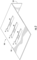
Figures 1- 4A are perspective views of vertical deflection connectors; -
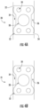
Figure 4B is a top view of a bushing element of a vertical deflection connector according to embodiments of the presently disclosed subject matter; -
Figures 5A and 5B are perspective views of steps in a process for creating vertical deflection connectors according to embodiments of the presently disclosed subject matter; -
Figures 6A and 6B are top views of a bushing element in a connected and disconnected relationship, respectively, with respect to a surrounding connector assembly structure; -
Figure 7 is a side view of a connector assembly coupled to a building element by a fastener; and -
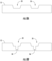
Figures 8A and 8B are side cutaway views of steps in a process for creating bushing elements of vertical deflection connectors according to an embodiment of the presently disclosed subject matter. - The present subject matter provides systems, assemblies, and methods for connecting vertical steel wall studs to a building structure in a manner to permit relative vertical movement but prevent relative horizontal movement therebetween. In particular, in one aspect, the present subject matter provides a connecting member for use in building assembly (e.g., as a vertical deflection connector). As illustrated in
Figures 1 and 2 , for example, a connector assembly, generally designated 10, can include a substantially rigid plate member 12 (e.g. a steel plate) having anelongated slot 14 formed therein, wherein the elongated slot includes opposed first andsecond edges plate member 12. - Another connecting member is shown in
Figure 3 in which a large connector plate, generally designated 100, similarly comprises a substantiallyrigid plate member 102 and aflange 103 that extends from an edge ofplate member 102.Large connector plate 100 can have a plurality ofelongated slots 14 formed therein. - Regardless of the particular configuration, the connector assemblies disclosed herein can each further include a bushing or washer element associated with each of the elongated slots formed in the substantially rigid plate members. Specifically, for example, referring again to the configuration shown in
Figure 1 , abushing 20 can comprise amain body 26 through which afastener center opening 28 can be provided. In some embodiments,main body 26 of bushing 20 can include aface 30, which can itself include adepressed area 40 that is substantially concentric with the fastener center opening 28 and is angled fromface 30 toward a center of fastener center opening 28. In this arrangement,depressed area 40 is adapted to receive a fastener (not show here) and guide the fastener into fastener center opening 28. -
Bushing 20 can be configured to be coupled toplate member 12 at an initial position withinslot 14. In particular, in the configuration shown inFigures 1 and 2 ,bushing 20 is coupled with the plate by one or more tabs connected to bushing 20 and toplate member 12. A detailed view of this configuration is shown inFigure 4A . As shown inFigures 1, 2 , and4A , bushing 20 can be connected toplate member 12 by afirst tab 22 that projects away from amain body 26 of bushing 20 and connects bushing 20 tofirst edge 16 ofslot 14. Similarly, asecond tab 24 can project away frommain body 26 of bushing 20 and connect bushing 20 tosecond edge 18 ofslot 14. In the particular configurations shown inFigures 1, 2 , and4A , for example,first tab 22 can connect a first corner of bushing 20 tofirst edge 16 ofslot 14, andsecond tab 24 can connect a diagonally opposing corner of bushing 20 tosecond edge 18 ofslot 14. - In accordance with the present invention, however, as shown in
Figure 4B , there may be no physical connection between bushing 20 andplate member 12, but bushing 20 is sized to have a width that is substantially similar to a width ofslot 14. In this configuration, although no tabs or other physical connector actually joins bushing 20 toplate member 12, bushing 20 is coupled toplate member 12 by friction. - In either configuration,
bushing 20 can be substantially retained inslot 14 at a desired initial position (e.g., by first andsecond tabs connector assembly 10 in a desired orientation with respect to other building elements to whichconnector assembly 10 will be coupled without having to separately alignbushing 20. As a result, installation ofconnector assembly 10 can be easier than using conventional connectors. - That being said,
connector assembly 10 is configured such that bushing 20 is movable relative toplate member 12 withinslot 14 upon application of a force exceeding a predetermined threshold value. For example, onceconnector assembly 10 is installed as part of a partition wall, it can be desirable to allow a degree of freedom of movement to reduce stress and possible fracture of connected parts as discussed above. In this regard, bushing 20 can be designed to be movable from its initial position as needed to allow such movement. Specifically, referring to the embodiments shown inFigures 1, 2 , and4A , first andsecond tabs plate member 12 and bushing 20. Loads that are sufficient to cause bushing 20 to break away can vary based on the material thickness selected for a given application. In some embodiments, for example, bushing 20 is designed to break away under applied loads in the range of 40 pounds for thinner steels (e.g., t = 0.03) and up to 200 pounds for heaver steels (e.g., t = 0.125). - Similarly, referring to
Figure 4B , abushing 20 can be designed to be movable relative toplate member 12 withinslot 14 if a force exerted betweenplate member 12 and bushing 20 exceeds the frictional force that holds bushing 20 in its position inslot 14. In any configuration, the force needed to cause bushing 20 to break away or otherwise become dislodged from its initial attached position is designed to not substantially affect the load-carrying capacity of the member it is supporting horizontally by applying an axial load through the attachment. - In some embodiments, to create a
connector assembly 10 having one of the configurations discussed herein,plate member 12 and bushing 20 can be formed from a single piece of sheet stock. Specifically, for example,Figures 5A and 5B illustrate exemplary steps in the formation ofconnector assembly 10. Referring toFigure 5A , first and secondparallel slits Figure 5A , first andsecond slits slot 14. - The formation of connector assembly further include forming a
depression 40 in an area substantially between first andsecond slits Depression 40 can further define the portion of blank 38 that can serve as bushing 20, although a connector opening need not be formed at the same time. In addition, the forming ofdepression 40 can displace the material of blank 38 so that first andsecond slits center line 42 ofdepression 40. As will be discussed below, this narrowing of first andsecond slits slot 14, even after first andsecond tabs - With the portion of blank 38 that can serve as bushing 20 substantially defined by one or more of first and
second slits depression 40,slot 14 can be formed by removing material from blank 38 beginning from first andsecond slits depression 40. In some embodiments, this removal of material can be controlled such that first andsecond tabs depression 40 is maintained in contact with the rest of blank 38. Finally, fastener center opening 28 can be formed throughdepression 40, wherebybushing 20 can thus be formed. - The above method can be applied to a blank having any of a variety of material thicknesses. That being said, in some embodiments, depending on the particular process by which material is removed from blank 38 (e.g., for the formation of first and
second slits 34 and 36), it can be difficult to achieve the desired sizes of one or more of the openings in blank 38 for greater thicknesses of blank 38. Specifically, for example, where blank 38 comprises a sheet of steel or other metal, one way to form first andsecond slits second slits bushing 20 withinslot 14. In addition, a narrow slit can help to reduce lateral motion of the connected building element (e.g., a wall stud) with respect to the anchorage point ofconnector assembly 10. - Furthermore, in conventional building practices, special fasteners with oversized heads are often not considered desirable for economic and practical reasons, and thus a "standard" screw can be preferred to be used in
coupling connector assembly 10 to an associated building element. Referring toFigures 6A and 6B , for example, afastener 60 having ahead portion 62 can be coupled with bushing 20 (i.e., to connectconnector assembly 10 to another building element).Fastener 60 is shown in phantom inFigures 6A and 6B so that the underlying structure can be clearly seen. When bushing 20 is in an attached state with respect toplate member 12 as shown inFigure 6A , bushing 20 can be substantially aligned at or near the center ofslot 14. In this arrangement,head 62 offastener 60 extends over the entire width ofslot 14 and overlaps withplate member 12 by afirst overlap region 63a. - In situations in which
bushing 20 breaks away fromplate member 12, however, the amount that head 62overlaps plate member 12 can be reduced to asecond overlap region 63b. To maintain secure coupling offastener 60 withconnector assembly 10, thissecond overlap region 63b should be sufficiently large that loads that are expected to be imparted betweenhead 62 andplate member 12 can be supported. In some embodiments, for example,second overlap region 63b is sized to be greater than the material thickness ofplate member 12. As noted above, because it can be preferable in many situations for fastener to be a standard size, controlling the size ofsecond overlap region 63b thus involves controlling one or more of the width ofslot 14, the width ofbushing 20, or the width of first andsecond slits head 62 can often be only marginally larger than the width ofslot 14, and thus any substantial movement ofbushing 20 to one side of slot 14 (See, e.g.,Figure 6B ) can result insecond overlap region 63b becoming too small to support the expected loads. As a result, it can be advantageous for first andsecond slits head 62 to disengage fromplate member 12. - To address this issue, the formation of
bushing 20 can involve narrowing the width of first andsecond slits depression 40 between first andsecond slits second slits bushing 20 and first andsecond edges slot 14. Alternatively or in addition, as shown inFigures 4A and 4B , one or more depressions ordimples 50 can be formed at or near the edges of the portion of blank 38 that defines bushing 20 to further displace material into first andsecond slits more bulges 52 that protrude from at least one edge ofbushing 20 into first andsecond slits second slits second edges slot 14. For instance, such a configuration can create the frictional engagement discussed above with respect to the embodiment Illustrated inFigure 4B . - In addition, dimples 50 can further serve to keep the head of an assembly screw away from contact with the surface of
plate member 12. Specifically, for example, as shown inFigure 7 , thefastener 60 can be inserted such thathead 62 bears on a convex portion ofdimples 50. This engagement with the protruding portion ofdimples 50 can holdhead 62 offastener 60 away from the surface ofplate member 12 by a small distance 51 (because the dimples are on the bushing, not the main clip surface). Alternatively or in addition, other features ofconnector assembly 10 can provide such an offset between the head of an assembly screw and the surface ofplate member 12. In some embodiments, for example, the edges of center opening 28 can be cupped either away or toward the screw head. In other embodiments, a recessed or protruding ring can be provided around center opening 28, where the edge of center opening 28 is flat and a recessed or protruded ring is provided a small distance outside the diameter. In yet further embodiments, the edges ofbushing 20 can be bent either away or toward the screw head. - Regardless of how this offset is produced, the resulting spacing allows
fastener 60 to be physically tightened to joinconnector assembly 10 with abuilding element 65 without rigidly engagingfastener 60 withplate member 12 directly, which can thereby allowbuilding element 65 to be movable with respect toplate member 12. In contrast, in competitive products without such a configuration for a bushing, the fastener must be loosened after assembly to allow such movement. Such loosening is an extra installation step, and further makes it possible for the fastener to work its way loose over time. - Alternatively, the size of first and
second slits Figures 8A and 8B , for example, rather than sizing first andsecond slits second indentation second slits Figure 8A ) Then, a second, narrower punch can be used to penetrate the now narrower thickness of blank 38 within first andsecond indentation second slits second indentations - Furthermore, in addition to narrowing the width of first and
second slits plate member 12 and/orbushing 20. Specifically, the formation of one or more ofdepression 40, dimples 50, or first andsecond indentations plate member 12 and/orbushing 20. Those having skill in the art will recognize that such plastic deformation can improve the material strength of these elements at those locations through work hardening. - Accordingly, this improvement in the material strength can be applied to the formation of
connector assembly 10 in areas other than those involving the formation of first andsecond slits Figure 2 illustrates an embodiment in which substantially the entireties offirst edge 16 andsecond edge 18 ofslot 14 are deformed. Because first andsecond edges plate member 12 that engagebushing 20 when lateral loads are applied between the connected building elements, improving the strength of first andsecond edges connector assembly 10 when exposed to such conditions. In addition, those having skill in the art will appreciate that such work hardening of other edges and interfaces ofconnector assembly 10 can provide further benefits to the strength ofconnector assembly 10. - Further in this regard, other features on a building element such as
connector assembly 10 can similarly be modified by work hardening to improve the strength of the elements. Specifically, for example, for a fastener-receiving opening in such a building element (e.g., forconnector assembly 10. fastener center opening 28 or the other openings shown in Figures 1A and 1B), the formation of such an opening can be accomplished by pressing and punching the area around which the opening is to be formed and substantially removing the material to form the opening. In some embodiments, the amount of work hardening that is applied can be controlled to achieve a desirable balance between the loss of material thickness and the improvement in the strength of the surrounding material resulting from the work hardening. Those having ordinary skill in the art should also recognize that this concept can be applied to any of a variety of connector elements for use in connecting building elements composed of any of a variety of construction materials (e.g., wood, steel) and is not necessarily limited to applications involving the connector assemblies that are particularly disclosed herein.
Claims (12)
- A connecting member (10, 100) for use in building assembly comprising:a substantially rigid plate (12, 102) having one or more elongated slots (14) formed therein, wherein at least one of the one or more elongated slots (14) comprises a first edge (16) and a second edge (18) along a longest dimension of a respective one of the one or more slots (14); anda bushing (20) coupled to the plate at an initial position within each of the one or more slots (14) but movable relative to the plate (12, 102) within a respective one of the one or more slots (14) upon application of a force exceeding a predetermined threshold value;wherein the bushing (20) has a width that is substantially similar to a width between the first edge (16) and the second edge (18) of the respective one of the one or more slots (14) such that the bushing (20) is coupled to the plate (12, 102) by a friction fit; andwherein the predetermined threshold value comprises a force magnitude required to overcome frictional engagement of the bushing (20) with the plate (12, 102).
- The connecting member of claim 1, wherein one or both of the first edge (16) and the second edge (18) are work hardened.
- The connecting member of any of the preceding claims, wherein the bushing (20) is coupled with the plate (12) by one or more tabs (22,24) connected to the bushing (20) and to the plate (12);
wherein the predetermined threshold value comprises a force magnitude required to break the one or more tabs (22,24). - The connecting member of any of the preceding claims, wherein the bushing (20) comprises one or more dimples (50) protruding from a surface of the bushing (20) relative to the substantially rigid plate (12), the one or more dimples (50) being configured to serve as a bearing surface against which a fastener is engagable without engaging the substantially rigid plate.
- The connecting member of any of the preceding claims, wherein the bushing comprises one or more bulges (52) protruding from at least one edge of the bushing (20), each of the one or more bulges (52) being associated with a depression formed in a surface of the bushing.
- The connecting member of claim 5, wherein the one or more bulges (52) protrude from the at least one edge of the bushing and contact an edge (16,18) of a respective one of the one or more slots (14).
- A method of preparing a connecting member for use in building assembly, the method comprising:forming a pair of substantially parallel slits (34,36) in a metal blank (38);forming a depression (40) between the substantially parallel slits (34,36);forming an elongated slot (14) by removing material beginning from the substantially parallel slits (34,36) for a predetermined length and width away from the depression (40);forming one or more dimples (50) at or near one or more edges of the bushing,wherein forming the one or more dimples (50) displaces a portion of the metal blank (38) surrounding the respective one of the one or more dimples so that the substantially parallel slits are narrowed,wherein a portion of the metal blank (38) surrounding each respective one of the one or more dimples (50) is displaced across substantially an entire width of a respective one of the substantially parallel slits (34,36),wherein the portion of the metal blank contacts a portion of the metal blank on an opposite edge of a respective one of the substantially parallel slits and is coupled to the portion of the metal blank by friction; andforming a connector opening through the depression to form a bushing in the blank;wherein the bushing is coupled to the blank at an initial position within the elongated slot but is movable relative to the blank within the elongated slot upon application of a force exceeding a predetermined threshold value; and
wherein the predetermined threshold value comprises a force magnitude required to overcome frictional engagement of the bushing with the plate. - The method of claim 7, wherein forming the pair of substantially parallel slits comprises:forming a pair of indentations (33,35) in the metal blank (38); andforming the pair of substantially parallel slits (34,36) within the pair of indentations;wherein a width of each of the substantially parallel slits (34,36) is less than a width of a respective one of the pair of indentations (33,35).
- The method of any of claim 7 or claim 8, wherein forming the depression displaces a portion of the metal blank (38) surrounding the depression (40) so that the substantially parallel slits (34,36) are narrowed along a centre line of the depression.
- The method of any of claims 7-9, wherein forming the elongated slot (14) comprises leaving intact one or more tabs connecting a portion of the metal blank containing the depression and a portion of the metal blank on an opposite edge of a respective one of the substantially parallel slits.
- The method of any of claims 7-10, comprising deforming one or more edges (16,18) of the elongated slot (14) to work harden the one or more edges.
- The method of any of claims 7-11, wherein forming the depression (40) comprisesdeforming an area of the metal blank (38) in which the connector opening (28) is to be formed such that material is work hardened; andwherein forming the connector opening (28) comprises removing a portion of the material within the area to create the connector opening;wherein a remaining portion of the area surrounding the opening exhibits improved strength.
Applications Claiming Priority (2)
| Application Number | Priority Date | Filing Date | Title |
|---|---|---|---|
| US201562204841P | 2015-08-13 | 2015-08-13 | |
| PCT/US2016/046744 WO2017027794A1 (en) | 2015-08-13 | 2016-08-12 | Connector systems, assemblies, and methods |
Publications (3)
| Publication Number | Publication Date |
|---|---|
| EP3334870A1 EP3334870A1 (en) | 2018-06-20 |
| EP3334870A4 EP3334870A4 (en) | 2019-03-13 |
| EP3334870B1 true EP3334870B1 (en) | 2024-11-06 |
Family
ID=57983711
Family Applications (1)
| Application Number | Title | Priority Date | Filing Date |
|---|---|---|---|
| EP16835970.1A Active EP3334870B1 (en) | 2015-08-13 | 2016-08-12 | Connector systems, assemblies, and methods |
Country Status (3)
| Country | Link |
|---|---|
| US (1) | US10132341B2 (en) |
| EP (1) | EP3334870B1 (en) |
| WO (1) | WO2017027794A1 (en) |
Families Citing this family (10)
| Publication number | Priority date | Publication date | Assignee | Title |
|---|---|---|---|---|
| USRE46844E1 (en) | 2012-07-06 | 2018-05-15 | The Steel Network, Inc. | Connector assembly for connecting building members |
| EP3334870B1 (en) | 2015-08-13 | 2024-11-06 | The Steel Network, Inc. | Connector systems, assemblies, and methods |
| CA2942452C (en) * | 2016-01-20 | 2023-08-01 | Simpson Strong-Tie Company, Inc. | Slide clip connector |
| CA3035219A1 (en) * | 2016-09-02 | 2018-03-08 | Simpson Strong-Tie Company, Inc. | Building structural connection comprising an angular bracket |
| US11299897B1 (en) * | 2019-01-17 | 2022-04-12 | Shane L. Saia | Apparatus, system, and method for assembling, aligning, leveling, and squaring in-ground pool walls |
| US11499306B2 (en) * | 2019-10-03 | 2022-11-15 | Thermacrete Llc | Differential settlement anchors |
| USD959251S1 (en) | 2020-07-22 | 2022-08-02 | Clarkwestern Dietrich Building Systems Llc | Slide clip |
| US11692340B2 (en) | 2020-07-22 | 2023-07-04 | Clarkwestern Dietrich Building Systems Llc | Slide clip |
| USD959250S1 (en) | 2020-07-22 | 2022-08-02 | Clarkwestern Dietrich Building Systems Llc | Slide clip |
| ES3066191T3 (en) * | 2022-08-30 | 2026-05-11 | Sfs Group Int Ag | Centering device, fixing arrangement and its use |
Citations (1)
| Publication number | Priority date | Publication date | Assignee | Title |
|---|---|---|---|---|
| US4060905A (en) * | 1976-08-19 | 1977-12-06 | Stanley Light | Gauge for mounting window-shade brackets |
Family Cites Families (26)
| Publication number | Priority date | Publication date | Assignee | Title |
|---|---|---|---|---|
| US3354689A (en) * | 1965-07-13 | 1967-11-28 | Colorado Oil And Gas Corp | Metal forming |
| CH609827B (en) * | 1975-09-16 | Ebauchesfabrik Eta Ag | PROCESS FOR PUNCHING A SMALL HOLE IN A FINE MECHANICAL WORKPIECE. | |
| US5313752A (en) * | 1991-01-11 | 1994-05-24 | Fero Holdings Limited | Wall framing system |
| US5467566A (en) | 1991-10-28 | 1995-11-21 | Swartz & Kulpa, Structural Design And Engineering | Curtain wall clip |
| US5606888A (en) * | 1995-07-14 | 1997-03-04 | The Whitaker Corp. | Method of forming relatively hard materials |
| US5846018A (en) * | 1996-08-26 | 1998-12-08 | Super Stud Building Products, Inc. | Deflection slide clip |
| US5906080A (en) | 1997-05-15 | 1999-05-25 | Digirolamo; Edward R. | Bracket for interconnecting a building stud to primary structural components |
| US5876006A (en) * | 1997-08-22 | 1999-03-02 | Scafco Corporation | Stud mounting clip |
| FR2768195B1 (en) * | 1997-09-05 | 1999-10-29 | Renault | SELF-RELEASING FIXING TO THE TIGHTENING, PARTICULARLY FOR A PLASTIC WING OF A MOTOR VEHICLE |
| GB2340751B (en) | 1998-08-12 | 2003-11-05 | Edko Trading Representation | Pharmaceutical compositions |
| US6213679B1 (en) | 1999-10-08 | 2001-04-10 | Super Stud Building Products, Inc. | Deflection slide clip |
| US6688069B2 (en) * | 2000-07-24 | 2004-02-10 | Unimast Incorporated | Vertical slide clip |
| US6612087B2 (en) | 2000-11-29 | 2003-09-02 | The Steel Network, Inc. | Building member connector allowing bi-directional relative movement |
| JP3736550B2 (en) * | 2002-07-30 | 2006-01-18 | セイコーエプソン株式会社 | Fine hole drilling apparatus, processing method therefor, and liquid jet head manufacturing method using the same |
| DE10236552B4 (en) * | 2002-08-08 | 2004-07-22 | Hilti Ag | Connection element for a mounting system |
| JP2004167547A (en) * | 2002-11-20 | 2004-06-17 | Nakamura Mfg Co Ltd | Method for shearing sheet |
| US7503150B1 (en) | 2003-10-20 | 2009-03-17 | The Steel Network, Inc. | Connector assembly for allowing relative movement between two building members |
| US7478508B2 (en) * | 2004-08-16 | 2009-01-20 | Scafco Corporation | Mounting clip |
| US20070113612A1 (en) * | 2005-11-22 | 2007-05-24 | Kato Seisakusyo Co., Ltd. | Manufacturing method for a press work product |
| DE102006020376A1 (en) * | 2006-04-28 | 2007-10-31 | Rehau Ag + Co | fastening device |
| NZ571534A (en) | 2007-09-25 | 2010-02-26 | Michael Norman Carr | An adjustable joist hanger |
| US8181419B1 (en) | 2009-12-03 | 2012-05-22 | The Steel Network, Inc. | Connector for connecting building members |
| US8683770B2 (en) | 2009-12-03 | 2014-04-01 | The Steel Network, Inc. | Connector assembly for connecting building members |
| DE102010045641A1 (en) * | 2010-09-17 | 2012-03-22 | Schott Ag | Process for producing a ring-shaped or plate-shaped element |
| USRE46844E1 (en) | 2012-07-06 | 2018-05-15 | The Steel Network, Inc. | Connector assembly for connecting building members |
| EP3334870B1 (en) | 2015-08-13 | 2024-11-06 | The Steel Network, Inc. | Connector systems, assemblies, and methods |
-
2016
- 2016-08-12 EP EP16835970.1A patent/EP3334870B1/en active Active
- 2016-08-12 WO PCT/US2016/046744 patent/WO2017027794A1/en not_active Ceased
- 2016-08-12 US US15/235,628 patent/US10132341B2/en active Active
Patent Citations (1)
| Publication number | Priority date | Publication date | Assignee | Title |
|---|---|---|---|---|
| US4060905A (en) * | 1976-08-19 | 1977-12-06 | Stanley Light | Gauge for mounting window-shade brackets |
Also Published As
| Publication number | Publication date |
|---|---|
| WO2017027794A1 (en) | 2017-02-16 |
| US10132341B2 (en) | 2018-11-20 |
| US20170044787A1 (en) | 2017-02-16 |
| EP3334870A1 (en) | 2018-06-20 |
| EP3334870A4 (en) | 2019-03-13 |
Similar Documents
| Publication | Publication Date | Title |
|---|---|---|
| US10132341B2 (en) | Connector systems, assemblies, and methods | |
| US8181419B1 (en) | Connector for connecting building members | |
| US8683770B2 (en) | Connector assembly for connecting building members | |
| US8347465B2 (en) | Clip | |
| US9982700B2 (en) | Fastener | |
| US20230228080A1 (en) | Fastener Alignment Guide, Connector and Method | |
| JP6795950B2 (en) | clip | |
| EP3631217B1 (en) | Self-piercing fastener | |
| EP3430273B1 (en) | U-clip assembly | |
| EP3730808B1 (en) | Fastener clip with push nut | |
| US7603814B1 (en) | Decking system hanger | |
| USRE46844E1 (en) | Connector assembly for connecting building members | |
| JP2009509103A (en) | Blind rivets and methods | |
| KR101973319B1 (en) | High strength hanger for clamping ceiling frame | |
| EP3329135B1 (en) | Tapered head clinch fastener | |
| JP5798593B2 (en) | Ceiling substrate and ceiling structure | |
| JP2546686Y2 (en) | Securing clip | |
| CA3119542C (en) | FASTENING FOR THIN SHEET MATERIAL | |
| EP1560989B1 (en) | Improved coupling element for inverted t beams | |
| US10697483B2 (en) | Tension bracket | |
| CN109538618B (en) | Fastening piece | |
| US20190195253A1 (en) | Linear Latching Systems and Methods | |
| US20210086454A1 (en) | Fastening element | |
| EP3571357B1 (en) | Drift clip | |
| KR20180002968U (en) | Device for clamping forms |
Legal Events
| Date | Code | Title | Description |
|---|---|---|---|
| STAA | Information on the status of an ep patent application or granted ep patent |
Free format text: STATUS: THE INTERNATIONAL PUBLICATION HAS BEEN MADE |
|
| PUAI | Public reference made under article 153(3) epc to a published international application that has entered the european phase |
Free format text: ORIGINAL CODE: 0009012 |
|
| STAA | Information on the status of an ep patent application or granted ep patent |
Free format text: STATUS: REQUEST FOR EXAMINATION WAS MADE |
|
| 17P | Request for examination filed |
Effective date: 20180313 |
|
| AK | Designated contracting states |
Kind code of ref document: A1 Designated state(s): AL AT BE BG CH CY CZ DE DK EE ES FI FR GB GR HR HU IE IS IT LI LT LU LV MC MK MT NL NO PL PT RO RS SE SI SK SM TR |
|
| AX | Request for extension of the european patent |
Extension state: BA ME |
|
| DAV | Request for validation of the european patent (deleted) | ||
| REG | Reference to a national code |
Ref country code: DE Ref legal event code: R079 Free format text: PREVIOUS MAIN CLASS: E04B0001380000 Ipc: F16B0005020000 |
|
| A4 | Supplementary search report drawn up and despatched |
Effective date: 20190212 |
|
| RIC1 | Information provided on ipc code assigned before grant |
Ipc: E04B 1/38 20060101ALI20190206BHEP Ipc: E04B 1/24 20060101ALI20190206BHEP Ipc: F16B 5/02 20060101AFI20190206BHEP Ipc: F16B 31/02 20060101ALI20190206BHEP |
|
| STAA | Information on the status of an ep patent application or granted ep patent |
Free format text: STATUS: EXAMINATION IS IN PROGRESS |
|
| 17Q | First examination report despatched |
Effective date: 20210629 |
|
| P01 | Opt-out of the competence of the unified patent court (upc) registered |
Effective date: 20230530 |
|
| GRAP | Despatch of communication of intention to grant a patent |
Free format text: ORIGINAL CODE: EPIDOSNIGR1 |
|
| STAA | Information on the status of an ep patent application or granted ep patent |
Free format text: STATUS: GRANT OF PATENT IS INTENDED |
|
| INTG | Intention to grant announced |
Effective date: 20240527 |
|
| GRAS | Grant fee paid |
Free format text: ORIGINAL CODE: EPIDOSNIGR3 |
|
| GRAA | (expected) grant |
Free format text: ORIGINAL CODE: 0009210 |
|
| STAA | Information on the status of an ep patent application or granted ep patent |
Free format text: STATUS: THE PATENT HAS BEEN GRANTED |
|
| AK | Designated contracting states |
Kind code of ref document: B1 Designated state(s): AL AT BE BG CH CY CZ DE DK EE ES FI FR GB GR HR HU IE IS IT LI LT LU LV MC MK MT NL NO PL PT RO RS SE SI SK SM TR |
|
| REG | Reference to a national code |
Ref country code: GB Ref legal event code: FG4D |
|
| REG | Reference to a national code |
Ref country code: CH Ref legal event code: EP |
|
| REG | Reference to a national code |
Ref country code: DE Ref legal event code: R096 Ref document number: 602016090157 Country of ref document: DE |
|
| REG | Reference to a national code |
Ref country code: IE Ref legal event code: FG4D |
|
| REG | Reference to a national code |
Ref country code: LT Ref legal event code: MG9D |
|
| REG | Reference to a national code |
Ref country code: NL Ref legal event code: MP Effective date: 20241106 |
|
| PG25 | Lapsed in a contracting state [announced via postgrant information from national office to epo] |
Ref country code: IS Free format text: LAPSE BECAUSE OF FAILURE TO SUBMIT A TRANSLATION OF THE DESCRIPTION OR TO PAY THE FEE WITHIN THE PRESCRIBED TIME-LIMIT Effective date: 20250306 Ref country code: HR Free format text: LAPSE BECAUSE OF FAILURE TO SUBMIT A TRANSLATION OF THE DESCRIPTION OR TO PAY THE FEE WITHIN THE PRESCRIBED TIME-LIMIT Effective date: 20241106 Ref country code: PT Free format text: LAPSE BECAUSE OF FAILURE TO SUBMIT A TRANSLATION OF THE DESCRIPTION OR TO PAY THE FEE WITHIN THE PRESCRIBED TIME-LIMIT Effective date: 20250306 |
|
| PG25 | Lapsed in a contracting state [announced via postgrant information from national office to epo] |
Ref country code: FI Free format text: LAPSE BECAUSE OF FAILURE TO SUBMIT A TRANSLATION OF THE DESCRIPTION OR TO PAY THE FEE WITHIN THE PRESCRIBED TIME-LIMIT Effective date: 20241106 Ref country code: NL Free format text: LAPSE BECAUSE OF FAILURE TO SUBMIT A TRANSLATION OF THE DESCRIPTION OR TO PAY THE FEE WITHIN THE PRESCRIBED TIME-LIMIT Effective date: 20241106 |
|
| REG | Reference to a national code |
Ref country code: AT Ref legal event code: MK05 Ref document number: 1739612 Country of ref document: AT Kind code of ref document: T Effective date: 20241106 |
|
| PG25 | Lapsed in a contracting state [announced via postgrant information from national office to epo] |
Ref country code: BG Free format text: LAPSE BECAUSE OF FAILURE TO SUBMIT A TRANSLATION OF THE DESCRIPTION OR TO PAY THE FEE WITHIN THE PRESCRIBED TIME-LIMIT Effective date: 20241106 |
|
| PG25 | Lapsed in a contracting state [announced via postgrant information from national office to epo] |
Ref country code: ES Free format text: LAPSE BECAUSE OF FAILURE TO SUBMIT A TRANSLATION OF THE DESCRIPTION OR TO PAY THE FEE WITHIN THE PRESCRIBED TIME-LIMIT Effective date: 20241106 |
|
| PG25 | Lapsed in a contracting state [announced via postgrant information from national office to epo] |
Ref country code: NO Free format text: LAPSE BECAUSE OF FAILURE TO SUBMIT A TRANSLATION OF THE DESCRIPTION OR TO PAY THE FEE WITHIN THE PRESCRIBED TIME-LIMIT Effective date: 20250206 |
|
| PG25 | Lapsed in a contracting state [announced via postgrant information from national office to epo] |
Ref country code: LV Free format text: LAPSE BECAUSE OF FAILURE TO SUBMIT A TRANSLATION OF THE DESCRIPTION OR TO PAY THE FEE WITHIN THE PRESCRIBED TIME-LIMIT Effective date: 20241106 Ref country code: GR Free format text: LAPSE BECAUSE OF FAILURE TO SUBMIT A TRANSLATION OF THE DESCRIPTION OR TO PAY THE FEE WITHIN THE PRESCRIBED TIME-LIMIT Effective date: 20250207 Ref country code: AT Free format text: LAPSE BECAUSE OF FAILURE TO SUBMIT A TRANSLATION OF THE DESCRIPTION OR TO PAY THE FEE WITHIN THE PRESCRIBED TIME-LIMIT Effective date: 20241106 |
|
| PG25 | Lapsed in a contracting state [announced via postgrant information from national office to epo] |
Ref country code: PL Free format text: LAPSE BECAUSE OF FAILURE TO SUBMIT A TRANSLATION OF THE DESCRIPTION OR TO PAY THE FEE WITHIN THE PRESCRIBED TIME-LIMIT Effective date: 20241106 |
|
| PG25 | Lapsed in a contracting state [announced via postgrant information from national office to epo] |
Ref country code: RS Free format text: LAPSE BECAUSE OF FAILURE TO SUBMIT A TRANSLATION OF THE DESCRIPTION OR TO PAY THE FEE WITHIN THE PRESCRIBED TIME-LIMIT Effective date: 20250206 |
|
| PG25 | Lapsed in a contracting state [announced via postgrant information from national office to epo] |
Ref country code: SM Free format text: LAPSE BECAUSE OF FAILURE TO SUBMIT A TRANSLATION OF THE DESCRIPTION OR TO PAY THE FEE WITHIN THE PRESCRIBED TIME-LIMIT Effective date: 20241106 |
|
| PG25 | Lapsed in a contracting state [announced via postgrant information from national office to epo] |
Ref country code: DK Free format text: LAPSE BECAUSE OF FAILURE TO SUBMIT A TRANSLATION OF THE DESCRIPTION OR TO PAY THE FEE WITHIN THE PRESCRIBED TIME-LIMIT Effective date: 20241106 |
|
| PG25 | Lapsed in a contracting state [announced via postgrant information from national office to epo] |
Ref country code: EE Free format text: LAPSE BECAUSE OF FAILURE TO SUBMIT A TRANSLATION OF THE DESCRIPTION OR TO PAY THE FEE WITHIN THE PRESCRIBED TIME-LIMIT Effective date: 20241106 |
|
| PG25 | Lapsed in a contracting state [announced via postgrant information from national office to epo] |
Ref country code: RO Free format text: LAPSE BECAUSE OF FAILURE TO SUBMIT A TRANSLATION OF THE DESCRIPTION OR TO PAY THE FEE WITHIN THE PRESCRIBED TIME-LIMIT Effective date: 20241106 |
|
| PG25 | Lapsed in a contracting state [announced via postgrant information from national office to epo] |
Ref country code: SK Free format text: LAPSE BECAUSE OF FAILURE TO SUBMIT A TRANSLATION OF THE DESCRIPTION OR TO PAY THE FEE WITHIN THE PRESCRIBED TIME-LIMIT Effective date: 20241106 |
|
| PG25 | Lapsed in a contracting state [announced via postgrant information from national office to epo] |
Ref country code: CZ Free format text: LAPSE BECAUSE OF FAILURE TO SUBMIT A TRANSLATION OF THE DESCRIPTION OR TO PAY THE FEE WITHIN THE PRESCRIBED TIME-LIMIT Effective date: 20241106 |
|
| PG25 | Lapsed in a contracting state [announced via postgrant information from national office to epo] |
Ref country code: IT Free format text: LAPSE BECAUSE OF FAILURE TO SUBMIT A TRANSLATION OF THE DESCRIPTION OR TO PAY THE FEE WITHIN THE PRESCRIBED TIME-LIMIT Effective date: 20241106 |
|
| REG | Reference to a national code |
Ref country code: DE Ref legal event code: R097 Ref document number: 602016090157 Country of ref document: DE |
|
| PG25 | Lapsed in a contracting state [announced via postgrant information from national office to epo] |
Ref country code: SE Free format text: LAPSE BECAUSE OF FAILURE TO SUBMIT A TRANSLATION OF THE DESCRIPTION OR TO PAY THE FEE WITHIN THE PRESCRIBED TIME-LIMIT Effective date: 20241106 |
|
| PLBE | No opposition filed within time limit |
Free format text: ORIGINAL CODE: 0009261 |
|
| STAA | Information on the status of an ep patent application or granted ep patent |
Free format text: STATUS: NO OPPOSITION FILED WITHIN TIME LIMIT |
|
| 26N | No opposition filed |
Effective date: 20250807 |
|
| REG | Reference to a national code |
Ref country code: DE Ref legal event code: R119 Ref document number: 602016090157 Country of ref document: DE |
|
| REG | Reference to a national code |
Ref country code: CH Ref legal event code: H13 Free format text: ST27 STATUS EVENT CODE: U-0-0-H10-H13 (AS PROVIDED BY THE NATIONAL OFFICE) Effective date: 20260324 |
|
| PG25 | Lapsed in a contracting state [announced via postgrant information from national office to epo] |
Ref country code: MC Free format text: LAPSE BECAUSE OF FAILURE TO SUBMIT A TRANSLATION OF THE DESCRIPTION OR TO PAY THE FEE WITHIN THE PRESCRIBED TIME-LIMIT Effective date: 20241106 |
|
| PG25 | Lapsed in a contracting state [announced via postgrant information from national office to epo] |
Ref country code: LU Free format text: LAPSE BECAUSE OF NON-PAYMENT OF DUE FEES Effective date: 20250812 |
|
| PG25 | Lapsed in a contracting state [announced via postgrant information from national office to epo] |
Ref country code: CH Free format text: LAPSE BECAUSE OF NON-PAYMENT OF DUE FEES Effective date: 20250831 |
|
| GBPC | Gb: european patent ceased through non-payment of renewal fee |
Effective date: 20250812 |