EP3334671B2 - Bellows connecting adjacent carriages, in particular carriages of a material handling sorter - Google Patents
Bellows connecting adjacent carriages, in particular carriages of a material handling sorter Download PDFInfo
- Publication number
- EP3334671B2 EP3334671B2 EP15794645.0A EP15794645A EP3334671B2 EP 3334671 B2 EP3334671 B2 EP 3334671B2 EP 15794645 A EP15794645 A EP 15794645A EP 3334671 B2 EP3334671 B2 EP 3334671B2
- Authority
- EP
- European Patent Office
- Prior art keywords
- bellows
- shelves
- base structure
- carriages
- bellows according
- Prior art date
- Legal status (The legal status is an assumption and is not a legal conclusion. Google has not performed a legal analysis and makes no representation as to the accuracy of the status listed.)
- Active
Links
Images


Classifications
-
- B—PERFORMING OPERATIONS; TRANSPORTING
- B07—SEPARATING SOLIDS FROM SOLIDS; SORTING
- B07C—POSTAL SORTING; SORTING INDIVIDUAL ARTICLES, OR BULK MATERIAL FIT TO BE SORTED PIECE-MEAL, e.g. BY PICKING
- B07C5/00—Sorting according to a characteristic or feature of the articles or material being sorted, e.g. by control effected by devices which detect or measure such characteristic or feature; Sorting by manually actuated devices, e.g. switches
- B07C5/36—Sorting apparatus characterised by the means used for distribution
-
- B—PERFORMING OPERATIONS; TRANSPORTING
- B65—CONVEYING; PACKING; STORING; HANDLING THIN OR FILAMENTARY MATERIAL
- B65G—TRANSPORT OR STORAGE DEVICES, e.g. CONVEYORS FOR LOADING OR TIPPING, SHOP CONVEYOR SYSTEMS OR PNEUMATIC TUBE CONVEYORS
- B65G47/00—Article or material-handling devices associated with conveyors; Methods employing such devices
- B65G47/74—Feeding, transfer, or discharging devices of particular kinds or types
- B65G47/94—Devices for flexing or tilting travelling structures; Throw-off carriages
- B65G47/96—Devices for tilting links or platform
-
- F—MECHANICAL ENGINEERING; LIGHTING; HEATING; WEAPONS; BLASTING
- F16—ENGINEERING ELEMENTS AND UNITS; GENERAL MEASURES FOR PRODUCING AND MAINTAINING EFFECTIVE FUNCTIONING OF MACHINES OR INSTALLATIONS; THERMAL INSULATION IN GENERAL
- F16J—PISTONS; CYLINDERS; SEALINGS
- F16J3/00—Diaphragms; Bellows; Bellows pistons
- F16J3/04—Bellows
- F16J3/048—Bellows with guiding or supporting means
Definitions
- the present invention refers to a bellows.
- the invention refers to a bellows connecting adjacent carriages of a material handling sorter and the following description is carried out with reference to this application field with the only purpose of simplifying the exposition.
- a bellows is a covering element generally having a pleated structure, having a predetermined number of substantially M-shaped elements usually being made of a pleated nylon fabric.
- bellows are particularly used in the material handling, for example in the so-called sorter handlers, each bellows being extended between a carriage and the adjacent carriage, in order to cover the space between the carriages.
- the bellows can also comprise plate-shaped inserts, inserted in said substantially M-shaped elements and each contacting on the upper part an internal vertex of one of said substantially M-shaped elements.
- a bellows according to the preamble of claim 1 is known from EP-A-2 386 432 .
- those bellows are completely passive elements, without any ability of sustaining any possible accidental load, incident from the outside, as it would be in the case where objects having very different weight and/or dimension from each other are to be managed, as it is typical for the parcel sector (couriers and shipping agents) and where it happens that some objects can overflow, in part or entirely, from the carriage wherein they were intended.
- the technical problem at the basis of the present invention is to provide a bellows having such structural and functional features as to overcome the drawbacks mentioned with reference to the prior art bellows.
- a bellows connecting adjacent carriages, in particular carriages of a material handling sorter along a predetermined path comprising opposite heads each being associated with a carriage and a pleated structure having a predetermined number of substantially M-shaped elements provided with a plurality of vertices, characterized in that it comprises a bearing structure formed by a base structure and by a frame slidingly abutting on said base structure, said base structure and said frame being rigid and cooperating with each other, being arranged between adjacent carriages inside said bellows.
- the base structure comprises shelves, each being associated with a respective head and cantilevering therefrom.
- Each of those shelves is divided into a plurality of shelves being suitably staggered in order to insert into each other like a comb, when pulling together and separating the carriages.
- Each shelf can further comprise a slat integral with the shelves forming a substantially right angle-shaped element, those slat being associated with a respective head.
- the frame can comprise a plurality of sheet inserts arranged inside the bellows having a pressing contact along respective vertices and slidingly abutting at the bottom on the shelves of the base structure, in order to support the pleated structure.
- each sheet insert can comprise a core sandwiched by two opposite metal covers, the entirety of the metal covers defining an extrados having a pressing contact with a respective vertex.
- the metal covers can have wings on the bottom being right angle laterally bent, slidingly abutting on a respective shelf of the base structure.
- the wings can comprise respective pairs of small wings facing towards a respective head, small wings of different metal covers associated with the same core being placed back-to-back, in opposite directions and having a predetermined corresponding width, defining a gap therebetween and forming, with respective small wings of a metal cover of an adjacent sheet insert, respective supporting feet having a pressing and sliding contact with one of the shelves.
- the cores of the sheet inserts can comprise protrusions facing downwards so as to follow the shape of the cover sandwiching them.
- the cores of the sheet inserts can be made of an elastomeric material, in particular PVC and the metal covers of the sheet inserts can be made of steel.
- the metal covers of the sheet inserts can have strengthening teeth facing downwards and arranged having a pitch corresponding to holes made in the covers themselves for the riveting.
- a bearing structure for a bellows connecting adjacent carriages, in particular carriages of a material handling sorter along a predetermined path comprising opposite heads each being associated with a carriage and a pleated structure having a predetermined number of substantially M-shaped elements provided with a plurality of vertices, such bearing structure comprising a base structure and a frame slidingly abutting on the base structure, being rigid and cooperating with each other, being arranged between adjacent carriages inside the bellows.
- a bellows according to the invention is globally indicated with 1 being usable within a sorter 2, in an extended position between a carriage 3 and an equal carriage (not shown), running along a path P of the sorter 2 itself; the bellows extends in order to cover the space S between the carriages and to connect the carriages themselves along the path P.
- the bellows 1 comprises opposite heads, 4a and 4b, each being associated with a respective carriage, in particular the head 4a being associated with the carriage 3 and the head 4b to the adjacent carriage.
- the bellows 1 also comprises a pleated structure 5, formed by a predetermined number of substantially M-shaped elements, all indicated with 6, five in the described example.
- Such substantially M-shaped elements 6 define a plurality of vertices, all indicated with 7, six in the described example.
- the ones that are at the ends of the pleated structure 5 are integral to the heads 4a and 4b.
- the bellows 1 according to the present invention also comprise a bearing structure 8, which is substantially accommodated in the space S between adjacent carriages, and is inside the bellows 1 being placed to cover that space S.
- the bearing structure 8 is formed by two different structures, being rigid and cooperating with each other, and precisely by a base structure 8' and a frame 8" slidingly abutting on the base structure 8'.
- the base structure 8' is provided with shelves 9a, 9b, each being associated with a respective head 4a, 4b and cantilevering in the space S between a carriage and the adjacent one.
- the shelves 9a being associated with the head 4a are two, indicated with 9a' and 9a" as well as the shelves 9b being associated with the head 4b are two, indicated with 9b' and 9b", bearing in mind that the shelves are suitably staggered in order to insert into each other like a comb, when pulling together and separating the carriages.
- the shelves 9a' and 9a" are integral with a slat 10a forming a substantially L or right angle -shaped element, such slat 10a being associated with the respective head 4a.
- the shelves 9b' and 9b" are integral with a slat 10b forming a further substantially right angle-shaped element being symmetrical to the former, such slat 10b being associated with the respective head 4b.
- the frame 8" comprises a plurality of sheet inserts, all globally indicated with 11, being arranged in the bellows 1 having a pressing contact along respective vertices 7 and slidingly abutting on the bottom on the shelves 9a, 9b of the base structure 8', in order to support the pleated structure 5.
- each sheet insert 11 includes a core 12, being preferably made of an elastomeric material, for example PVC, sandwiched by two opposite metal covers 13a, 13b, being preferably made of steel.
- the entirety of the metal covers 13a, 13b defines an extrados 13', having a pressing contact with a respective vertex 7 and an opposite intrados 13".
- the metal covers 13a, 13b have wings 14 on the bottom being right angle laterally bent, slidingly abutting on a respective shelf 9a, 9b of the base structure 8'.
- the wings of the metal cover 13a are made of a pair of small wings 15a and 16a facing the head 4a, while the wings of the metal cover 13b are made of a pair of small wings 15b and 16b facing the head 4b. It must be noted that the small wings 15a, 16a, 15b, 16b are placed back-to-back, in opposite directions and have a predetermined corresponding width, defining a gap I therebetween.
- the covers of an adjacent sheet insert have small wings 17a, 17b, which are respectively facing the heads 4a and 4b, are placed back-to-back and have a predetermined limited width being substantially equal to the gap I.
- the small wings 15a, 15b, 16a, 16b, 17a, 17b as a whole form a sort of supporting foot, globally indicated with W' in the figure, having a pressing and sliding contact with one of the shelves, in particular with the shelf 9a' of the base structure 8'.
- a supporting foot W" is obtained with right angle folded wings having a reduced width and abutting the shelf 9a" of the base structure 8'.
- the metal covers 13a, 13b of the sheet inserts 11 have strengthening teeth 18 at the intradoses 13", facing downwards and being arranged having a pitch corresponding to holes 19 made in the covers and intended for the riveting, in particular in a slat horizontal portion thereof.
- the strengthening teeth 18 form a strengthening of the sheet inserts 11 at the weakening being caused by the holes 19 for the riveting.
- the cores 12 being made of PVC have protrusions 20 facing downwards following the shape of the covers 13a, 13b sandwiching them.
- the sheet inserts 11 have the vertical portion made of a metal/PVC/metal multilayer, only the right angle portion of the wings 14 being made of metal only.
- resolings are provided at the small wings 15a, 15b, 16a, 16b, 17a, 17b with sheets made of a proper material, in particular an adhesive antifriction or self-lubricant material, so as to facilitate the sliding of the supporting feet W', W" on the respective shelves 9a', 9a" of the base structure 8'.
- the present invention extends also to a bearing structure 8 for a bellows 1 connecting adjacent carriages 3, in particular carriages of a material handling sorter 2 along a preset path P, the bellows comprising opposite heads 4a, 4b, each being associated with a carriage 3 and a pleated structure 5 having a predetermined number of substantially M-shaped elements 6 provided with a plurality of vertices;
- the bearing structure 8 comprises a base structure 8' and a frame 8" slidingly abutting on said base structure 8', being rigid and cooperating with each other, being arranged between adjacent carriages inside the bellows 1.
- the main advantage of the bellows according to the invention is the fact that it has an unusual strength, lending an unexceptionable operating safety to the sorter where it is intended, also in the occurrence of objects to be transported possibly overflowing from the carriages.
- Another advantage of the bellows according to the invention is its simple structure, which is a non-negligible advantage for an item intended for a large or very large scale production.
- bellows according to the invention has the advantage to be easily realized in field and applied to existing sorters, starting from known bellows.
Landscapes
- Engineering & Computer Science (AREA)
- Mechanical Engineering (AREA)
- General Engineering & Computer Science (AREA)
- Blinds (AREA)
Description
- The present invention refers to a bellows.
- More specifically, the invention refers to a bellows connecting adjacent carriages of a material handling sorter and the following description is carried out with reference to this application field with the only purpose of simplifying the exposition.
- As it is well known, a bellows is a covering element generally having a pleated structure, having a predetermined number of substantially M-shaped elements usually being made of a pleated nylon fabric.
- Those bellows are particularly used in the material handling, for example in the so-called sorter handlers, each bellows being extended between a carriage and the adjacent carriage, in order to cover the space between the carriages.
- The bellows can also comprise plate-shaped inserts, inserted in said substantially M-shaped elements and each contacting on the upper part an internal vertex of one of said substantially M-shaped elements.
- A bellows according to the preamble of
claim 1 is known fromEP-A-2 386 432 . - Nevertheless, those bellows are completely passive elements, without any ability of sustaining any possible accidental load, incident from the outside, as it would be in the case where objects having very different weight and/or dimension from each other are to be managed, as it is typical for the parcel sector (couriers and shipping agents) and where it happens that some objects can overflow, in part or entirely, from the carriage wherein they were intended.
- The known bellows, in the case of objects being accidentally weighing thereon, are deformed, warped, and even broken, incurring in failures of the system operation.
- Trying to overcome these drawbacks, the bellows often are disused in favor of telescopic coverages incurring in building difficulties and in operational limitations, for example regarding the path of the carriages on bends.
- The technical problem at the basis of the present invention is to provide a bellows having such structural and functional features as to overcome the drawbacks mentioned with reference to the prior art bellows.
- The above-mentioned technical problem is solved by a bellows connecting adjacent carriages, in particular carriages of a material handling sorter along a predetermined path, comprising opposite heads each being associated with a carriage and a pleated structure having a predetermined number of substantially M-shaped elements provided with a plurality of vertices, characterized in that it comprises a bearing structure formed by a base structure and by a frame slidingly abutting on said base structure, said base structure and said frame being rigid and cooperating with each other, being arranged between adjacent carriages inside said bellows.
- According to the invention, the base structure comprises shelves, each being associated with a respective head and cantilevering therefrom.
- Each of those shelves is divided into a plurality of shelves being suitably staggered in order to insert into each other like a comb, when pulling together and separating the carriages.
- Each shelf can further comprise a slat integral with the shelves forming a substantially right angle-shaped element, those slat being associated with a respective head.
- According to another aspect of the invention, the frame can comprise a plurality of sheet inserts arranged inside the bellows having a pressing contact along respective vertices and slidingly abutting at the bottom on the shelves of the base structure, in order to support the pleated structure.
- In particular, each sheet insert can comprise a core sandwiched by two opposite metal covers, the entirety of the metal covers defining an extrados having a pressing contact with a respective vertex.
- According to another aspect of the invention, the metal covers can have wings on the bottom being right angle laterally bent, slidingly abutting on a respective shelf of the base structure.
- In particular, the wings can comprise respective pairs of small wings facing towards a respective head, small wings of different metal covers associated with the same core being placed back-to-back, in opposite directions and having a predetermined corresponding width, defining a gap therebetween and forming, with respective small wings of a metal cover of an adjacent sheet insert, respective supporting feet having a pressing and sliding contact with one of the shelves.
- According to another aspect of the invention, the cores of the sheet inserts can comprise protrusions facing downwards so as to follow the shape of the cover sandwiching them.
- According to another aspect of the invention, the cores of the sheet inserts can be made of an elastomeric material, in particular PVC and the metal covers of the sheet inserts can be made of steel.
- Moreover, the metal covers of the sheet inserts can have strengthening teeth facing downwards and arranged having a pitch corresponding to holes made in the covers themselves for the riveting.
- The problem is also solved by a bearing structure for a bellows connecting adjacent carriages, in particular carriages of a material handling sorter along a predetermined path, comprising opposite heads each being associated with a carriage and a pleated structure having a predetermined number of substantially M-shaped elements provided with a plurality of vertices, such bearing structure comprising a base structure and a frame slidingly abutting on the base structure, being rigid and cooperating with each other, being arranged between adjacent carriages inside the bellows.
- The characteristics and advantages of the bellows and bearing structure according to the invention will be apparent from the following description of an embodiment thereof given by way of a non-limiting example with reference to the attached drawings.
- In such drawings:
-
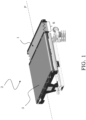
Figure 1 represents a schematic perspective view of a sorter comprising a bellows according to the invention; -
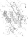
Figure 2 represents a bottom perspective view of a bellows according to the invention; -
Figure 3 represents a top perspective view of the bellows ofFigure 2 from another angle; -
Figure 4 represents a top perspective view of a detail of the bellows ofFigure 3 ; and -
Figure 5 represents an exploded top perspective view of the bellows ofFigure 2 . - With reference to the attached figures, a bellows according to the invention is globally indicated with 1 being usable within a
sorter 2, in an extended position between acarriage 3 and an equal carriage (not shown), running along a path P of thesorter 2 itself; the bellows extends in order to cover the space S between the carriages and to connect the carriages themselves along the path P. - The
bellows 1 comprises opposite heads, 4a and 4b, each being associated with a respective carriage, in particular thehead 4a being associated with thecarriage 3 and thehead 4b to the adjacent carriage. Thebellows 1 also comprises apleated structure 5, formed by a predetermined number of substantially M-shaped elements, all indicated with 6, five in the described example. Such substantially M-shaped elements 6 define a plurality of vertices, all indicated with 7, six in the described example. - More particularly, of the substantially M-
shaped elements 6, the ones that are at the ends of thepleated structure 5 are integral to theheads - The
bellows 1 according to the present invention also comprise abearing structure 8, which is substantially accommodated in the space S between adjacent carriages, and is inside thebellows 1 being placed to cover that space S. - The
bearing structure 8 is formed by two different structures, being rigid and cooperating with each other, and precisely by a base structure 8' and aframe 8" slidingly abutting on the base structure 8'. - The base structure 8' is provided with
shelves respective head - In particular, the
shelves 9a being associated with thehead 4a are two, indicated with 9a' and 9a" as well as theshelves 9b being associated with thehead 4b are two, indicated with 9b' and 9b", bearing in mind that the shelves are suitably staggered in order to insert into each other like a comb, when pulling together and separating the carriages. - Structurally, it must be noted that the
shelves 9a' and 9a" are integral with a slat 10a forming a substantially L or right angle -shaped element,such slat 10a being associated with therespective head 4a. Similarly, theshelves 9b' and 9b" are integral with a slat 10b forming a further substantially right angle-shaped element being symmetrical to the former,such slat 10b being associated with therespective head 4b. - The
frame 8" comprises a plurality of sheet inserts, all globally indicated with 11, being arranged in thebellows 1 having a pressing contact alongrespective vertices 7 and slidingly abutting on the bottom on theshelves pleated structure 5. - In the described example, each
sheet insert 11 includes acore 12, being preferably made of an elastomeric material, for example PVC, sandwiched by twoopposite metal covers metal covers respective vertex 7 and anopposite intrados 13". - The metal covers 13a, 13b have
wings 14 on the bottom being right angle laterally bent, slidingly abutting on arespective shelf - In the described example, the wings of the
metal cover 13a are made of a pair ofsmall wings head 4a, while the wings of themetal cover 13b are made of a pair ofsmall wings head 4b. It must be noted that thesmall wings - Similarly, the covers of an adjacent sheet insert have
small wings heads small wings shelf 9a' of the base structure 8'. - In a similar way, a supporting foot W" is obtained with right angle folded wings having a reduced width and abutting the
shelf 9a" of the base structure 8'. - In the shown example, the metal covers 13a, 13b of the
sheet inserts 11 have strengtheningteeth 18 at theintradoses 13", facing downwards and being arranged having a pitch corresponding toholes 19 made in the covers and intended for the riveting, in particular in a slat horizontal portion thereof. Thereby, the strengtheningteeth 18 form a strengthening of thesheet inserts 11 at the weakening being caused by theholes 19 for the riveting. - It must also be noticed that the
cores 12 being made of PVC haveprotrusions 20 facing downwards following the shape of thecovers sheet inserts 11 have the vertical portion made of a metal/PVC/metal multilayer, only the right angle portion of thewings 14 being made of metal only. - Preferably, resolings are provided at the
small wings respective shelves 9a', 9a" of the base structure 8'. - It must be noted that the present invention extends also to a
bearing structure 8 for abellows 1 connectingadjacent carriages 3, in particular carriages of amaterial handling sorter 2 along a preset path P, the bellows comprisingopposite heads carriage 3 and apleated structure 5 having a predetermined number of substantially M-shaped elements 6 provided with a plurality of vertices; in particular thebearing structure 8 comprises a base structure 8' and aframe 8" slidingly abutting on said base structure 8', being rigid and cooperating with each other, being arranged between adjacent carriages inside thebellows 1. - The main advantage of the bellows according to the invention is the fact that it has an unusual strength, lending an unexceptionable operating safety to the sorter where it is intended, also in the occurrence of objects to be transported possibly overflowing from the carriages.
- Another advantage of the bellows according to the invention is its simple structure, which is a non-negligible advantage for an item intended for a large or very large scale production.
- It must be noted that the bellows according to the invention has the advantage to be easily realized in field and applied to existing sorters, starting from known bellows.
- Finally, a further advantage expected from the bellows according to the invention is a long useful life with constant efficiency.
- Obviously, in order to meet contingent and specific requirements, a skilled person in the art could bring several changes and variations to the above described bellows, all included within the scope of protection of the invention as defined by the following claims.
Claims (10)
- A bellows (1) connecting adjacent carriages (3) of a material handling sorter (2) along a predetermined path (P), comprising opposite heads (4a, 4b) each being associated with a carriage (3) and a pleated structure (5) having a predetermined number of substantially M-shaped elements (6) provided with a plurality of vertices (7), characterized in that it comprises a bearing structure (8) formed by a base structure (8') and by a frame (8") slidingly abutting on said base structure (8'), said base structure (8') and said frame (8") being rigid and cooperating with each other, being arranged between adjacent carriages inside said bellows (1) and in that said base structure (8') comprises shelves (9a, 9b), each being associated with a respective head (4a, 4b) and cantilevering therefromand characterized in that each of said shelves (9a, 9b) is divided into a plurality of shelves (9a', 9a", 9b', 9b") being suitably staggered in order to insert into each other like a comb, when pulling together and separating said carriages.
- The bellows according to claim 1, characterized in that each of said shelves (9a', 9a", 9b', 9b") further includes a slat (10a, 10b) being integral with said shelves (9a', 9a", 9b', 9b") forming a substantially right angle-shaped element, said slat (10a, 10b) being associated with a respective head (4a, 4b).
- The bellows according to claim 2, characterized in that said frame (8") comprises a plurality of sheet inserts (11) being arranged inside said bellows (1) having a pressing contact along respective vertices (7) and slidingly abutting at the bottom on said shelves (9a, 9b) of said base structure (8'), in order to support said pleated structure (5).
- The bellows according to claim 3, characterized in that each of said sheet inserts (11) comprises a core (12) being sandwiched by two opposite metal covers (13a, 13b), the entirety of said metal covers (13a, 13b) defining an extrados (13'), having a pressing contact with a respective vertex (7).
- The bellows according to claim 4, characterized in that said metal covers (13a, 13b) have wings (14) on the bottom being right angle laterally bent , slidingly abutting on a respective shelf (9a, 9b) of said base structure (8').
- The bellows according to claim 5, characterized in that said wings (14) comprises respective pairs of small wings (15a, 16a, 15b, 16b) facing towards a respective head (4a, 4b), small wings of different metal covers (13a, 13b) associated with the same core (12) being placed back-to-back, in opposite directions and having a predetermined corresponding width, defining a gap (I) therebetween and forming, with respective small wings (17a, 17b) of a metal cover of an adjacent sheet insert, respective supporting feet (W', W") having a pressing and sliding contact with one of said shelves (9a', 9a", 9b', 9b").
- The bellows according to claim 6, characterized in that said cores (12) of said sheet inserts (11) comprise protrusions (20) facing downwards so as to follow the shape of said covers (13a, 13b) sandwiching them.
- The bellows according to any claim from 4 to 7, characterized in that said cores (12) of said sheet inserts (11) are made of an elastomeric material, in particular PVC.
- The bellows according to any claim from 4 to 8, characterized in that said metal covers (13a, 13b) of said sheet inserts (11) are made of steel.
- The bellows according to any claim from 4 to 9, characterized in that said metal covers (13a, 13b) of said sheet inserts (11) comprise strengthening teeth (18) facing downwards and being arranged having a pitch corresponding to holes (19) made in said metal covers (13a, 13b) for the riveting.
Applications Claiming Priority (1)
| Application Number | Priority Date | Filing Date | Title |
|---|---|---|---|
| PCT/IT2015/000200 WO2017025991A1 (en) | 2015-08-10 | 2015-08-10 | Bellows connecting adjacent carriages, in particular carriages of a material handling sorter |
Publications (3)
| Publication Number | Publication Date |
|---|---|
| EP3334671A1 EP3334671A1 (en) | 2018-06-20 |
| EP3334671B1 EP3334671B1 (en) | 2020-01-29 |
| EP3334671B2 true EP3334671B2 (en) | 2023-04-12 |
Family
ID=54542478
Family Applications (1)
| Application Number | Title | Priority Date | Filing Date |
|---|---|---|---|
| EP15794645.0A Active EP3334671B2 (en) | 2015-08-10 | 2015-08-10 | Bellows connecting adjacent carriages, in particular carriages of a material handling sorter |
Country Status (5)
| Country | Link |
|---|---|
| US (1) | US10898929B2 (en) |
| EP (1) | EP3334671B2 (en) |
| AU (1) | AU2015405319B2 (en) |
| DK (1) | DK3334671T4 (en) |
| WO (1) | WO2017025991A1 (en) |
Families Citing this family (8)
| Publication number | Priority date | Publication date | Assignee | Title |
|---|---|---|---|---|
| US10329094B1 (en) * | 2018-05-11 | 2019-06-25 | Intelligrated Headquarters, Llc | Conveyor carriers with gap cover |
| ES3005846T3 (en) | 2019-11-08 | 2025-03-17 | Leonardo Spa | Closure system of the interconnection of transport units connected to each other in a convoy |
| IT202000000310A1 (en) * | 2019-11-08 | 2021-07-10 | Leonardo Spa | CLOSURE SYSTEM FOR THE INTERCONNECTION OF TRANSPORT UNITS CONNECTED TO EACH ONE IN A CONVEYANCE |
| EP3950542A1 (en) * | 2020-08-03 | 2022-02-09 | P.E.I. Protezioni Elaborazioni Industriali S.r.l. | Protective device and corresponding vehicle |
| IT202100003209A1 (en) | 2021-02-12 | 2022-08-12 | La Protec Srl | BELLOWS PROTECTION FOR CONNECTION BETWEEN ADJACENT CARTS OF A CONVEYOR BELT |
| IT202100024740A1 (en) * | 2021-09-28 | 2023-03-28 | Viola Group Srl | BELLOWS PROTECTION WITH INCREASED CAPACITY |
| DE102022134280B3 (en) * | 2022-12-21 | 2024-03-07 | Coop Systems GmbH | Sorting conveyors, in particular cross-belt sorters or tilting tray sorters, for transporting and sorting piece goods |
| CN121158485A (en) * | 2024-06-19 | 2025-12-19 | 因特利格雷特总部有限责任公司 | Top cover for cross-belt frame of conveyor system |
Family Cites Families (13)
| Publication number | Priority date | Publication date | Assignee | Title |
|---|---|---|---|---|
| US2707117A (en) * | 1948-02-03 | 1955-04-26 | Chicago Metal Hose Corp | Reinforced flexible bellows joint |
| FR2617453B1 (en) | 1987-07-01 | 1989-10-20 | Caoutchouc Manuf Plastique | DEVICE FOR ENSURING THE CONTINUITY OF PASSAGE BETWEEN TWO SUCCESSIVE RAILWAY OR ROAD VEHICLES |
| DE3724069C1 (en) * | 1987-07-21 | 1989-03-16 | Witzenmann Metallschlauchfab | Bendable hose with mutually parallel ring-shaped shafts and axial support |
| JP3662639B2 (en) * | 1995-08-10 | 2005-06-22 | 剛 根本 | Bellows |
| JP2002066866A (en) | 2000-09-04 | 2002-03-05 | Disco Abrasive Syst Ltd | Bellows device |
| DE102006002655B4 (en) | 2006-01-19 | 2008-03-06 | Hübner GmbH | Bellows a transition between two articulated vehicles |
| US8733777B2 (en) * | 2010-02-05 | 2014-05-27 | HÜBNER GmbH & Co. KG | Corrugation bellows of a transfer between two pivotably interconnected vehicles |
| EP2386432B1 (en) | 2010-05-11 | 2013-04-03 | Hübner GmbH | Articulated vehicle |
| US9243711B2 (en) * | 2011-07-19 | 2016-01-26 | Vetco Gray Inc. | Bi-directional pressure energized axial seal and a swivel connection application |
| CN104411603B (en) | 2012-07-11 | 2016-10-26 | 德马泰克公司 | Halved belt sorter system and article sorting method |
| FR3006031B1 (en) * | 2013-05-24 | 2015-10-02 | Weir Power & Ind France | REINFORCED METAL BELLOW SHAPE SEALING DEVICE. |
| EP2899433B1 (en) * | 2014-01-28 | 2016-11-23 | P.E.I. Protezioni Elaborazioni Industriali S.r.l. | Protective bellows and protection method for machine tool with laser processing device |
| US10557550B2 (en) * | 2015-04-10 | 2020-02-11 | Mide Technology Corporation | Flexible joint |
-
2015
- 2015-08-10 WO PCT/IT2015/000200 patent/WO2017025991A1/en not_active Ceased
- 2015-08-10 AU AU2015405319A patent/AU2015405319B2/en active Active
- 2015-08-10 EP EP15794645.0A patent/EP3334671B2/en active Active
- 2015-08-10 US US15/750,524 patent/US10898929B2/en active Active
- 2015-08-10 DK DK15794645.0T patent/DK3334671T4/en active
Non-Patent Citations (13)
| Title |
|---|
| 06610_00014_a01.pdf † |
| 094423.330.00004 EN C01 - building lay out 22 † |
| 094423-350-40520-EN-A01.PDF † |
| 11471-499.pdf † |
| 1147-864.pdf † |
| Affidavit by Mr. Ron Jut † |
| Annex to D22 † |
| Annex to D22. † |
| Declaration Mr. Frits Verhees † |
| Declaration Mr. Ron Jut † |
| Drawing 11471-999 † |
| Sales contract dated 24 June 2003 † |
| Video 'JLub.mp4' † |
Also Published As
| Publication number | Publication date |
|---|---|
| DK3334671T4 (en) | 2023-05-01 |
| WO2017025991A1 (en) | 2017-02-16 |
| US10898929B2 (en) | 2021-01-26 |
| DK3334671T3 (en) | 2020-04-27 |
| US20180221918A1 (en) | 2018-08-09 |
| EP3334671A1 (en) | 2018-06-20 |
| AU2015405319A1 (en) | 2018-03-01 |
| EP3334671B1 (en) | 2020-01-29 |
| AU2015405319B2 (en) | 2020-12-10 |
Similar Documents
| Publication | Publication Date | Title |
|---|---|---|
| EP3334671B2 (en) | Bellows connecting adjacent carriages, in particular carriages of a material handling sorter | |
| CN110775165B (en) | Structural element | |
| EP0057865A1 (en) | Platform structure of the pallet type | |
| US9376809B1 (en) | Decking member | |
| CA2650150A1 (en) | Metal pallet | |
| US2492626A (en) | Pallet construction | |
| EP2641506B1 (en) | Ultra-thin shelf for displaying articles, configured to be mounted on a shelving device | |
| EP4477583A2 (en) | Flexible reticular structure | |
| US10358262B2 (en) | Shaft packaging body | |
| EP3819226B1 (en) | Pallet | |
| US20180291622A1 (en) | Suspended ceiling beam with a reinforced bulb | |
| KR101153848B1 (en) | Resistance and ease of processing and assembly metal pellet manufacturing method thereof | |
| EP1901019B1 (en) | Bearing construction for high power liquid condensers and coolers | |
| JP6868360B2 (en) | container | |
| KR101350940B1 (en) | Tie beam for fixing palette supporting load beam and manufacturing method thereof | |
| KR20200056678A (en) | Assembly type stacking rack | |
| CN110461751B (en) | Elevator bumper cap | |
| EP3048070B1 (en) | System for storage and transportation of industrial products | |
| CN108323945B (en) | Combined goods shelf | |
| IT202200004413U1 (en) | BOX AND ASSEMBLY FOR GOODS MANAGEMENT | |
| KR20130006835U (en) | Checked plate for ship | |
| ITMI992196A1 (en) | METALLIC STRUCTURE OF STORAGE AND OR HANDLING OF MATERIALS | |
| US20130015156A1 (en) | Cross Bar Support For Use With Storage Racks | |
| TWI652396B (en) | Ceiling grid with enhanced loading capacity and capable of prevent blank panel from falling and related suppression element | |
| CN204341552U (en) | Window regulator transfer carton |
Legal Events
| Date | Code | Title | Description |
|---|---|---|---|
| STAA | Information on the status of an ep patent application or granted ep patent |
Free format text: STATUS: THE INTERNATIONAL PUBLICATION HAS BEEN MADE |
|
| PUAI | Public reference made under article 153(3) epc to a published international application that has entered the european phase |
Free format text: ORIGINAL CODE: 0009012 |
|
| STAA | Information on the status of an ep patent application or granted ep patent |
Free format text: STATUS: REQUEST FOR EXAMINATION WAS MADE |
|
| 17P | Request for examination filed |
Effective date: 20180206 |
|
| AK | Designated contracting states |
Kind code of ref document: A1 Designated state(s): AL AT BE BG CH CY CZ DE DK EE ES FI FR GB GR HR HU IE IS IT LI LT LU LV MC MK MT NL NO PL PT RO RS SE SI SK SM TR |
|
| AX | Request for extension of the european patent |
Extension state: BA ME |
|
| DAV | Request for validation of the european patent (deleted) | ||
| DAX | Request for extension of the european patent (deleted) | ||
| GRAP | Despatch of communication of intention to grant a patent |
Free format text: ORIGINAL CODE: EPIDOSNIGR1 |
|
| STAA | Information on the status of an ep patent application or granted ep patent |
Free format text: STATUS: GRANT OF PATENT IS INTENDED |
|
| INTG | Intention to grant announced |
Effective date: 20190904 |
|
| GRAS | Grant fee paid |
Free format text: ORIGINAL CODE: EPIDOSNIGR3 |
|
| GRAA | (expected) grant |
Free format text: ORIGINAL CODE: 0009210 |
|
| STAA | Information on the status of an ep patent application or granted ep patent |
Free format text: STATUS: THE PATENT HAS BEEN GRANTED |
|
| AK | Designated contracting states |
Kind code of ref document: B1 Designated state(s): AL AT BE BG CH CY CZ DE DK EE ES FI FR GB GR HR HU IE IS IT LI LT LU LV MC MK MT NL NO PL PT RO RS SE SI SK SM TR |
|
| REG | Reference to a national code |
Ref country code: GB Ref legal event code: FG4D |
|
| REG | Reference to a national code |
Ref country code: CH Ref legal event code: EP |
|
| REG | Reference to a national code |
Ref country code: AT Ref legal event code: REF Ref document number: 1228382 Country of ref document: AT Kind code of ref document: T Effective date: 20200215 |
|
| REG | Reference to a national code |
Ref country code: IE Ref legal event code: FG4D |
|
| REG | Reference to a national code |
Ref country code: DE Ref legal event code: R096 Ref document number: 602015046115 Country of ref document: DE |
|
| REG | Reference to a national code |
Ref country code: DK Ref legal event code: T3 Effective date: 20200423 |
|
| REG | Reference to a national code |
Ref country code: NL Ref legal event code: FP |
|
| PG25 | Lapsed in a contracting state [announced via postgrant information from national office to epo] |
Ref country code: PT Free format text: LAPSE BECAUSE OF FAILURE TO SUBMIT A TRANSLATION OF THE DESCRIPTION OR TO PAY THE FEE WITHIN THE PRESCRIBED TIME-LIMIT Effective date: 20200621 Ref country code: NO Free format text: LAPSE BECAUSE OF FAILURE TO SUBMIT A TRANSLATION OF THE DESCRIPTION OR TO PAY THE FEE WITHIN THE PRESCRIBED TIME-LIMIT Effective date: 20200429 Ref country code: FI Free format text: LAPSE BECAUSE OF FAILURE TO SUBMIT A TRANSLATION OF THE DESCRIPTION OR TO PAY THE FEE WITHIN THE PRESCRIBED TIME-LIMIT Effective date: 20200129 Ref country code: RS Free format text: LAPSE BECAUSE OF FAILURE TO SUBMIT A TRANSLATION OF THE DESCRIPTION OR TO PAY THE FEE WITHIN THE PRESCRIBED TIME-LIMIT Effective date: 20200129 |
|
| REG | Reference to a national code |
Ref country code: LT Ref legal event code: MG4D |
|
| PG25 | Lapsed in a contracting state [announced via postgrant information from national office to epo] |
Ref country code: HR Free format text: LAPSE BECAUSE OF FAILURE TO SUBMIT A TRANSLATION OF THE DESCRIPTION OR TO PAY THE FEE WITHIN THE PRESCRIBED TIME-LIMIT Effective date: 20200129 Ref country code: LV Free format text: LAPSE BECAUSE OF FAILURE TO SUBMIT A TRANSLATION OF THE DESCRIPTION OR TO PAY THE FEE WITHIN THE PRESCRIBED TIME-LIMIT Effective date: 20200129 Ref country code: SE Free format text: LAPSE BECAUSE OF FAILURE TO SUBMIT A TRANSLATION OF THE DESCRIPTION OR TO PAY THE FEE WITHIN THE PRESCRIBED TIME-LIMIT Effective date: 20200129 Ref country code: GR Free format text: LAPSE BECAUSE OF FAILURE TO SUBMIT A TRANSLATION OF THE DESCRIPTION OR TO PAY THE FEE WITHIN THE PRESCRIBED TIME-LIMIT Effective date: 20200430 Ref country code: BG Free format text: LAPSE BECAUSE OF FAILURE TO SUBMIT A TRANSLATION OF THE DESCRIPTION OR TO PAY THE FEE WITHIN THE PRESCRIBED TIME-LIMIT Effective date: 20200429 Ref country code: IS Free format text: LAPSE BECAUSE OF FAILURE TO SUBMIT A TRANSLATION OF THE DESCRIPTION OR TO PAY THE FEE WITHIN THE PRESCRIBED TIME-LIMIT Effective date: 20200529 |
|
| REG | Reference to a national code |
Ref country code: DE Ref legal event code: R026 Ref document number: 602015046115 Country of ref document: DE |
|
| PG25 | Lapsed in a contracting state [announced via postgrant information from national office to epo] |
Ref country code: ES Free format text: LAPSE BECAUSE OF FAILURE TO SUBMIT A TRANSLATION OF THE DESCRIPTION OR TO PAY THE FEE WITHIN THE PRESCRIBED TIME-LIMIT Effective date: 20200129 Ref country code: LT Free format text: LAPSE BECAUSE OF FAILURE TO SUBMIT A TRANSLATION OF THE DESCRIPTION OR TO PAY THE FEE WITHIN THE PRESCRIBED TIME-LIMIT Effective date: 20200129 Ref country code: SK Free format text: LAPSE BECAUSE OF FAILURE TO SUBMIT A TRANSLATION OF THE DESCRIPTION OR TO PAY THE FEE WITHIN THE PRESCRIBED TIME-LIMIT Effective date: 20200129 Ref country code: RO Free format text: LAPSE BECAUSE OF FAILURE TO SUBMIT A TRANSLATION OF THE DESCRIPTION OR TO PAY THE FEE WITHIN THE PRESCRIBED TIME-LIMIT Effective date: 20200129 Ref country code: CZ Free format text: LAPSE BECAUSE OF FAILURE TO SUBMIT A TRANSLATION OF THE DESCRIPTION OR TO PAY THE FEE WITHIN THE PRESCRIBED TIME-LIMIT Effective date: 20200129 Ref country code: EE Free format text: LAPSE BECAUSE OF FAILURE TO SUBMIT A TRANSLATION OF THE DESCRIPTION OR TO PAY THE FEE WITHIN THE PRESCRIBED TIME-LIMIT Effective date: 20200129 Ref country code: SM Free format text: LAPSE BECAUSE OF FAILURE TO SUBMIT A TRANSLATION OF THE DESCRIPTION OR TO PAY THE FEE WITHIN THE PRESCRIBED TIME-LIMIT Effective date: 20200129 |
|
| PLBI | Opposition filed |
Free format text: ORIGINAL CODE: 0009260 |
|
| PLAX | Notice of opposition and request to file observation + time limit sent |
Free format text: ORIGINAL CODE: EPIDOSNOBS2 |
|
| 26 | Opposition filed |
Opponent name: VANDERLANDE INDUSTRIES B.V. Effective date: 20201027 |
|
| PG25 | Lapsed in a contracting state [announced via postgrant information from national office to epo] |
Ref country code: SI Free format text: LAPSE BECAUSE OF FAILURE TO SUBMIT A TRANSLATION OF THE DESCRIPTION OR TO PAY THE FEE WITHIN THE PRESCRIBED TIME-LIMIT Effective date: 20200129 Ref country code: PL Free format text: LAPSE BECAUSE OF FAILURE TO SUBMIT A TRANSLATION OF THE DESCRIPTION OR TO PAY THE FEE WITHIN THE PRESCRIBED TIME-LIMIT Effective date: 20200129 |
|
| PLBB | Reply of patent proprietor to notice(s) of opposition received |
Free format text: ORIGINAL CODE: EPIDOSNOBS3 |
|
| PG25 | Lapsed in a contracting state [announced via postgrant information from national office to epo] |
Ref country code: MC Free format text: LAPSE BECAUSE OF FAILURE TO SUBMIT A TRANSLATION OF THE DESCRIPTION OR TO PAY THE FEE WITHIN THE PRESCRIBED TIME-LIMIT Effective date: 20200129 |
|
| REG | Reference to a national code |
Ref country code: CH Ref legal event code: PL |
|
| PG25 | Lapsed in a contracting state [announced via postgrant information from national office to epo] |
Ref country code: CH Free format text: LAPSE BECAUSE OF NON-PAYMENT OF DUE FEES Effective date: 20200831 Ref country code: LI Free format text: LAPSE BECAUSE OF NON-PAYMENT OF DUE FEES Effective date: 20200831 Ref country code: LU Free format text: LAPSE BECAUSE OF NON-PAYMENT OF DUE FEES Effective date: 20200810 |
|
| REG | Reference to a national code |
Ref country code: BE Ref legal event code: MM Effective date: 20200831 |
|
| PG25 | Lapsed in a contracting state [announced via postgrant information from national office to epo] |
Ref country code: BE Free format text: LAPSE BECAUSE OF NON-PAYMENT OF DUE FEES Effective date: 20200831 Ref country code: IE Free format text: LAPSE BECAUSE OF NON-PAYMENT OF DUE FEES Effective date: 20200810 |
|
| PG25 | Lapsed in a contracting state [announced via postgrant information from national office to epo] |
Ref country code: TR Free format text: LAPSE BECAUSE OF FAILURE TO SUBMIT A TRANSLATION OF THE DESCRIPTION OR TO PAY THE FEE WITHIN THE PRESCRIBED TIME-LIMIT Effective date: 20200129 Ref country code: MT Free format text: LAPSE BECAUSE OF FAILURE TO SUBMIT A TRANSLATION OF THE DESCRIPTION OR TO PAY THE FEE WITHIN THE PRESCRIBED TIME-LIMIT Effective date: 20200129 Ref country code: CY Free format text: LAPSE BECAUSE OF FAILURE TO SUBMIT A TRANSLATION OF THE DESCRIPTION OR TO PAY THE FEE WITHIN THE PRESCRIBED TIME-LIMIT Effective date: 20200129 |
|
| PG25 | Lapsed in a contracting state [announced via postgrant information from national office to epo] |
Ref country code: MK Free format text: LAPSE BECAUSE OF FAILURE TO SUBMIT A TRANSLATION OF THE DESCRIPTION OR TO PAY THE FEE WITHIN THE PRESCRIBED TIME-LIMIT Effective date: 20200129 Ref country code: AL Free format text: LAPSE BECAUSE OF FAILURE TO SUBMIT A TRANSLATION OF THE DESCRIPTION OR TO PAY THE FEE WITHIN THE PRESCRIBED TIME-LIMIT Effective date: 20200129 |
|
| REG | Reference to a national code |
Ref country code: AT Ref legal event code: UEP Ref document number: 1228382 Country of ref document: AT Kind code of ref document: T Effective date: 20200129 |
|
| PUAH | Patent maintained in amended form |
Free format text: ORIGINAL CODE: 0009272 |
|
| STAA | Information on the status of an ep patent application or granted ep patent |
Free format text: STATUS: PATENT MAINTAINED AS AMENDED |
|
| 27A | Patent maintained in amended form |
Effective date: 20230412 |
|
| AK | Designated contracting states |
Kind code of ref document: B2 Designated state(s): AL AT BE BG CH CY CZ DE DK EE ES FI FR GB GR HR HU IE IS IT LI LT LU LV MC MK MT NL NO PL PT RO RS SE SI SK SM TR |
|
| REG | Reference to a national code |
Ref country code: DE Ref legal event code: R102 Ref document number: 602015046115 Country of ref document: DE |
|
| REG | Reference to a national code |
Ref country code: DK Ref legal event code: T4 Effective date: 20230426 |
|
| REG | Reference to a national code |
Ref country code: NL Ref legal event code: FP |
|
| PGFP | Annual fee paid to national office [announced via postgrant information from national office to epo] |
Ref country code: NL Payment date: 20250821 Year of fee payment: 11 |
|
| PGFP | Annual fee paid to national office [announced via postgrant information from national office to epo] |
Ref country code: DE Payment date: 20250820 Year of fee payment: 11 Ref country code: DK Payment date: 20250825 Year of fee payment: 11 |
|
| PGFP | Annual fee paid to national office [announced via postgrant information from national office to epo] |
Ref country code: IT Payment date: 20250825 Year of fee payment: 11 |
|
| PGFP | Annual fee paid to national office [announced via postgrant information from national office to epo] |
Ref country code: GB Payment date: 20250821 Year of fee payment: 11 |
|
| PGFP | Annual fee paid to national office [announced via postgrant information from national office to epo] |
Ref country code: FR Payment date: 20250828 Year of fee payment: 11 Ref country code: AT Payment date: 20250821 Year of fee payment: 11 |
|
| REG | Reference to a national code |
Ref country code: AT Ref legal event code: UEP Ref document number: 1228382 Country of ref document: AT Kind code of ref document: T Effective date: 20230412 |