EP3334263A1 - Printed circuit board, corresponding lighting module, lighting system and method for implementing lighting modules - Google Patents
Printed circuit board, corresponding lighting module, lighting system and method for implementing lighting modules Download PDFInfo
- Publication number
- EP3334263A1 EP3334263A1 EP17205871.1A EP17205871A EP3334263A1 EP 3334263 A1 EP3334263 A1 EP 3334263A1 EP 17205871 A EP17205871 A EP 17205871A EP 3334263 A1 EP3334263 A1 EP 3334263A1
- Authority
- EP
- European Patent Office
- Prior art keywords
- printed circuit
- circuit board
- positive terminal
- lighting module
- terminal
- Prior art date
- Legal status (The legal status is an assumption and is not a legal conclusion. Google has not performed a legal analysis and makes no representation as to the accuracy of the status listed.)
- Granted
Links
Images





Classifications
-
- H—ELECTRICITY
- H05—ELECTRIC TECHNIQUES NOT OTHERWISE PROVIDED FOR
- H05K—PRINTED CIRCUITS; CASINGS OR CONSTRUCTIONAL DETAILS OF ELECTRIC APPARATUS; MANUFACTURE OF ASSEMBLAGES OF ELECTRICAL COMPONENTS
- H05K1/00—Printed circuits
- H05K1/02—Details
- H05K1/0286—Programmable, customizable or modifiable circuits
- H05K1/029—Programmable, customizable or modifiable circuits having a programmable lay-out, i.e. adapted for choosing between a few possibilities
-
- H—ELECTRICITY
- H05—ELECTRIC TECHNIQUES NOT OTHERWISE PROVIDED FOR
- H05B—ELECTRIC HEATING; ELECTRIC LIGHT SOURCES NOT OTHERWISE PROVIDED FOR; CIRCUIT ARRANGEMENTS FOR ELECTRIC LIGHT SOURCES, IN GENERAL
- H05B45/00—Circuit arrangements for operating light-emitting diodes [LED]
- H05B45/40—Details of LED load circuits
- H05B45/44—Details of LED load circuits with an active control inside an LED matrix
- H05B45/48—Details of LED load circuits with an active control inside an LED matrix having LEDs organised in strings and incorporating parallel shunting devices
-
- H—ELECTRICITY
- H05—ELECTRIC TECHNIQUES NOT OTHERWISE PROVIDED FOR
- H05K—PRINTED CIRCUITS; CASINGS OR CONSTRUCTIONAL DETAILS OF ELECTRIC APPARATUS; MANUFACTURE OF ASSEMBLAGES OF ELECTRICAL COMPONENTS
- H05K1/00—Printed circuits
- H05K1/02—Details
- H05K1/11—Printed elements for providing electric connections to or between printed circuits
-
- H—ELECTRICITY
- H05—ELECTRIC TECHNIQUES NOT OTHERWISE PROVIDED FOR
- H05K—PRINTED CIRCUITS; CASINGS OR CONSTRUCTIONAL DETAILS OF ELECTRIC APPARATUS; MANUFACTURE OF ASSEMBLAGES OF ELECTRICAL COMPONENTS
- H05K1/00—Printed circuits
- H05K1/18—Printed circuits structurally associated with non-printed electric components
- H05K1/181—Printed circuits structurally associated with non-printed electric components associated with surface mounted components
-
- H—ELECTRICITY
- H05—ELECTRIC TECHNIQUES NOT OTHERWISE PROVIDED FOR
- H05K—PRINTED CIRCUITS; CASINGS OR CONSTRUCTIONAL DETAILS OF ELECTRIC APPARATUS; MANUFACTURE OF ASSEMBLAGES OF ELECTRICAL COMPONENTS
- H05K13/00—Apparatus or processes specially adapted for manufacturing or adjusting assemblages of electric components
-
- H—ELECTRICITY
- H05—ELECTRIC TECHNIQUES NOT OTHERWISE PROVIDED FOR
- H05B—ELECTRIC HEATING; ELECTRIC LIGHT SOURCES NOT OTHERWISE PROVIDED FOR; CIRCUIT ARRANGEMENTS FOR ELECTRIC LIGHT SOURCES, IN GENERAL
- H05B45/00—Circuit arrangements for operating light-emitting diodes [LED]
- H05B45/20—Controlling the colour of the light
-
- H—ELECTRICITY
- H05—ELECTRIC TECHNIQUES NOT OTHERWISE PROVIDED FOR
- H05B—ELECTRIC HEATING; ELECTRIC LIGHT SOURCES NOT OTHERWISE PROVIDED FOR; CIRCUIT ARRANGEMENTS FOR ELECTRIC LIGHT SOURCES, IN GENERAL
- H05B45/00—Circuit arrangements for operating light-emitting diodes [LED]
- H05B45/30—Driver circuits
- H05B45/37—Converter circuits
-
- H—ELECTRICITY
- H05—ELECTRIC TECHNIQUES NOT OTHERWISE PROVIDED FOR
- H05B—ELECTRIC HEATING; ELECTRIC LIGHT SOURCES NOT OTHERWISE PROVIDED FOR; CIRCUIT ARRANGEMENTS FOR ELECTRIC LIGHT SOURCES, IN GENERAL
- H05B45/00—Circuit arrangements for operating light-emitting diodes [LED]
- H05B45/30—Driver circuits
- H05B45/395—Linear regulators
-
- H—ELECTRICITY
- H05—ELECTRIC TECHNIQUES NOT OTHERWISE PROVIDED FOR
- H05K—PRINTED CIRCUITS; CASINGS OR CONSTRUCTIONAL DETAILS OF ELECTRIC APPARATUS; MANUFACTURE OF ASSEMBLAGES OF ELECTRICAL COMPONENTS
- H05K2201/00—Indexing scheme relating to printed circuits covered by H05K1/00
- H05K2201/10—Details of components or other objects attached to or integrated in a printed circuit board
- H05K2201/10007—Types of components
- H05K2201/10106—Light emitting diode [LED]
-
- H—ELECTRICITY
- H05—ELECTRIC TECHNIQUES NOT OTHERWISE PROVIDED FOR
- H05K—PRINTED CIRCUITS; CASINGS OR CONSTRUCTIONAL DETAILS OF ELECTRIC APPARATUS; MANUFACTURE OF ASSEMBLAGES OF ELECTRICAL COMPONENTS
- H05K2201/00—Indexing scheme relating to printed circuits covered by H05K1/00
- H05K2201/10—Details of components or other objects attached to or integrated in a printed circuit board
- H05K2201/10227—Other objects, e.g. metallic pieces
- H05K2201/10363—Jumpers, i.e. non-printed cross-over connections
-
- H—ELECTRICITY
- H05—ELECTRIC TECHNIQUES NOT OTHERWISE PROVIDED FOR
- H05K—PRINTED CIRCUITS; CASINGS OR CONSTRUCTIONAL DETAILS OF ELECTRIC APPARATUS; MANUFACTURE OF ASSEMBLAGES OF ELECTRICAL COMPONENTS
- H05K2203/00—Indexing scheme relating to apparatus or processes for manufacturing printed circuits covered by H05K3/00
- H05K2203/02—Details related to mechanical or acoustic processing, e.g. drilling, punching, cutting, using ultrasound
- H05K2203/0228—Cutting, sawing, milling or shearing
-
- H—ELECTRICITY
- H05—ELECTRIC TECHNIQUES NOT OTHERWISE PROVIDED FOR
- H05K—PRINTED CIRCUITS; CASINGS OR CONSTRUCTIONAL DETAILS OF ELECTRIC APPARATUS; MANUFACTURE OF ASSEMBLAGES OF ELECTRICAL COMPONENTS
- H05K2203/00—Indexing scheme relating to apparatus or processes for manufacturing printed circuits covered by H05K3/00
- H05K2203/17—Post-manufacturing processes
- H05K2203/173—Adding connections between adjacent pads or conductors, e.g. for modifying or repairing
-
- H—ELECTRICITY
- H05—ELECTRIC TECHNIQUES NOT OTHERWISE PROVIDED FOR
- H05K—PRINTED CIRCUITS; CASINGS OR CONSTRUCTIONAL DETAILS OF ELECTRIC APPARATUS; MANUFACTURE OF ASSEMBLAGES OF ELECTRICAL COMPONENTS
- H05K2203/00—Indexing scheme relating to apparatus or processes for manufacturing printed circuits covered by H05K3/00
- H05K2203/17—Post-manufacturing processes
- H05K2203/175—Configurations of connections suitable for easy deletion, e.g. modifiable circuits or temporary conductors for electroplating; Processes for deleting connections
-
- H—ELECTRICITY
- H05—ELECTRIC TECHNIQUES NOT OTHERWISE PROVIDED FOR
- H05K—PRINTED CIRCUITS; CASINGS OR CONSTRUCTIONAL DETAILS OF ELECTRIC APPARATUS; MANUFACTURE OF ASSEMBLAGES OF ELECTRICAL COMPONENTS
- H05K3/00—Apparatus or processes for manufacturing printed circuits
- H05K3/22—Secondary treatment of printed circuits
- H05K3/222—Completing of printed circuits by adding non-printed jumper connections
Definitions
- the description relates to printed circuit boards for lighting modules and to corresponding lighting modules.
- a lighting system typically includes an electronic converter 10 and at least one lighting module 20.
- the electronic converter 10 may include an AC/DC or DC/DC switching supply, receiving at input a supply signal (e.g. from the mains or from a battery) and providing at output a regulated voltage V out or a regulated current i out .
- a supply signal e.g. from the mains or from a battery
- a lighting module 20 includes one or more light radiation sources including e.g. at least one LED (Light Emitting Diode) or other solid-state lighting means such as e.g. laser diodes.
- LED Light Emitting Diode
- other solid-state lighting means such as e.g. laser diodes.
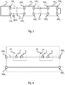
- Figure 1 shows a system wherein the electronic converter is a voltage generator 10 V and similarly the lighting modules 20 are modules 20 V configured to be supplied with a voltage.
- Figure 1 shows two lighting modules 20 V1 and 20 V2 .
- the electronic converter 10 V provides at output, via a positive terminal 100a and a negative terminal 100b, which represents a ground GND, a regulated voltage V out .
- Figure 2 shows an example of a lighting module 20 V configured to be supplied with a regulated voltage V out .
- lighting module 20 V includes a positive input terminal 200a and a negative input terminal 200b, for the connection to the terminals 100a and 100b of electronic converter 10 V .
- lighting module 20 V may be connected, via a cable C1, to the electronic converter 10 V . Therefore, terminal 200a is connected to terminal 100a, and terminal 200b is connected to terminal 100b, and therefore the lighting module 20 receives the voltage V out .
- the lighting module 20 V is a LED module including one or more LEDs L connected between the terminals 200a and 200b.
- module 20 V may include a LED chain or string 22, wherein a plurality of LEDs is connected in series.
- the LEDs L may also be distributed onto various branches connected in parallel.
- module 20 V may include a first LED string 22a including a first set of LEDs connected in series, and a second LED string 22b including a second set of LEDs L connected in series.
- the lighting module 20 includes a current regulator 24 connected in series with each LED string 22.
- the first LED string 22a and a first current regulator 24 are connected (e.g. directly) in series between the terminals 200a and 200b
- the second LED string 22b and a second current regulator 24 are connected (e.g. directly) in series between the terminals 200a and 200b.
- the strings 22a and 22b are supplied with a common voltage ( V out ).
- V out a common voltage
- the LED strings 22 with the respective current regulators 24 included in the various lighting modules 20 V should be connected in parallel at the voltage V out provided by the electronic converter 10 V .
- the lighting modules 20 V should be electrically connected in parallel to voltage V out .
- the lighting module 20 V1 also includes a positive output terminal 200c and a negative output terminal 200d, for the connection to a following lighting module, for example module 20 V2 .
- said terminals 200c/200d are connected (e.g. directly) to the terminals 200a/200b. Therefore, the voltage ( V out ) received at the terminals 200a and 200b is also applied to the terminals 200c and 200d.
- the terminals 200a and 200b of the lighting module 20 V2 may be connected (directly or via a cable C2) to the terminals 100a and 100b of the electronic converter 10 V , or to the terminals 200c and 200d of the lighting module 20 V1 , which again provide the voltage V out .
- the electric connection is in parallel.
- the current regulator 24 may be a resistor or a linear current regulator.
- the current regulator 24 may also be implemented by means of current mirrors or a switched mode current source regulator, typically including an inductor and an electronic switch.
- Figure 3 shows a system wherein the electronic converter is a current generator 10 C , and similarly the lighting modules 20 are modules 20 C configured to be supplied with a current.
- the electronic converter is a current generator 10 C
- the lighting modules 20 are modules 20 C configured to be supplied with a current.
- Figure 3 shows two lighting modules 20 C1 and 20 C2 .
- the electronic converter 10 C provides at output via the positive terminal 100a and the negative terminal 100b, which again represents a ground GND, a regulated current i out .
- the LEDs L distributed throughout the various lighting modules 20 are connected in series between the terminals 100a and 100b.
- each lighting module 20 C includes two terminals 200a and 200b.
- the LEDs L of said module are connected in series between the terminals 200a and 200b.
- each lighting module 20 C moreover includes two terminals 200c and 200d for the connection to the terminals 200a and 200b of a following lighting module 20 C .
- the terminals 200c and 200d of the last lighting module 20 C for example module 20 C2 , are short-circuited (internally or externally) to close the current path.
- each lighting module 20c may be connected in series between the terminals 200a and 200c and/or between the terminals 200d and 200b.
- two LED strings 22a and 22b are connected in series between the terminals 200a and 200c, and terminal 200d is connected (e.g. directly) to terminal 200b.
- a plurality of LED strings may be connected in parallel, optionally having a resistor connected in series in order to improve the current distribution among the various strings.
- a resistor connected in series in order to improve the current distribution among the various strings.
- each lighting module 20 has a structure which changes as a function of the envisaged supply (voltage or current supply). Moreover, according to the needs, each lighting module 20 may include a different number of LEDs.
- the lighting module 20 in order to improve the characteristics of a lighting module 20, in particular as regards efficiency, light emission and LED pitch, the lighting module 20 must be designed specifically. For example, the designer must choose the correct LEDs, e.g. as regards spectral characteristic (colour) and brightness, and he must design a rigid or a flexible printed circuit board. While designing said printed circuit board, the designer must also take into account the electric configuration of the circuit (current or voltage driving) and the sizing specifications of the printed circuit board.
- the LEDs L of a module 20 V may easily be replaced with LEDs of a different colour.
- the brightness of module 20 V may be varied, by modifying the current flowing through the LED string 22, e.g. by adapting current regulator 24 e.g. by modifying the reference resistor of a corresponding current regulator.
- the lighting modules 20 C with current supply may be re-used.
- document EP 2 805 101 A1 shows LED modules which may be cut to different lengths.
- the electronic converter 10 C must be adapted.
- the present description aims at providing solutions for implementing rigid or flexible printed circuit boards for lighting modules which may be re-used more easily.
- said object is achieved thanks to a printed circuit board having the features set forth in the claims that follow.
- the claims also concern a corresponding lighting module, lighting system and method for implementing lighting modules.
- various embodiments of the present specification concern a printed circuit board for a lighting module.
- the printed circuit board includes metallic zones including a first positive terminal and a first negative terminal, typically used for the connection to an electronic converter.
- the metallic zones also include a second positive terminal, which may be used for connecting the respective lighting module to a previous module.
- the metallic zones may include a third positive terminal and a second negative terminal (connected via an electric trace to the first negative terminal) which may be used for connecting the respective lighting module to a following module.
- the printed circuit board may include a fourth positive terminal, connected (via an electric trace to the first negative terminal) to the first positive terminal. For example, this terminal may be useful if a plurality of lighting modules are connected in parallel to the electronic converter.
- the metallic zones moreover include electric contacts for mounting one or more LEDs, and electric traces between these contacts, so that the LEDs are connected in series by forming a LED string.
- the printed circuit board includes selection means, implemented by means of electric traces and metallic contacts adapted to be short-circuited via links, so as to enable all the following connections:
- the selection means enable configuring the lighting module either as a single module or as the first, intermediate or last module of a chain of modules.
- the lighting module is a single lighting module or if it belongs to a string of lighting modules.
- the selection means are set so that the LED string is connected between the first positive terminal and the first negative terminal, alternatively between the second positive terminal and the first negative terminal.
- the lighting module belongs to a string of lighting modules, it is determined (at least) whether the lighting module is the first or the last lighting module of the string of lighting modules. If the lighting module is the first lighting module of the string of lighting modules, the selection means are set so that the LED string is connected between the first positive terminal and the third positive terminal, or alternatively between the second positive terminal and the third positive terminal. On the other hand, if the lighting module is the last lighting module of the string of lighting modules, the selection means are set so that the LED string is connected between the second positive terminal and the first negative terminal. Finally, if the lighting module is an intermediate module of the string of lighting modules, the selection means are set so that the LED string is connected between the second positive terminal and the third positive terminal.
- the selection means may include:
- both contacts of said sets are metallic contacts having a SMD format 1H/0201, 1E/0402, 1J/0603, 2A/0805 or 2B/1206.
- the lighting module includes a printed circuit board, wherein one or more LEDs are mounted on the printed circuit board. Moreover, both contacts of the first set or alternatively of the second set are closed via a link, and both contacts of the third set or alternatively of the fourth set are closed via a link.
- the printed circuit board includes bypass means, implemented by means of electric traces, and/or metallic contacts configured to be short-circuited, in order to selectively bypass one or more of the LEDs.
- the printed circuit board may include electric contacts for mounting or implementing a current regulator, and further bypass means implemented by means of electric traces and/or metallic contacts, configured to be short-circuited in order to selectively bypass the current regulator.
- said regulator and the respective bypass means may be used in order to implement lighting modules which may be supplied with a regulated voltage or alternatively with a regulated current.
- the advantages mentioned in the foregoing may be achieved by a single printed circuit board, which may be reconfigured.
- some electric connections may be enabled selectively via jumpers or by soldering resistors or bridges / wire links, such as zero-Ohm resistors, onto the printed circuit board.
- the same printed circuit board may therefore be used in order to implement:
- various embodiments may also be employed for solutions wherein the light emitted by two LED strings (distributed on one or more LED modules) may be adjusted (so-called dimming) independently, therefore leading to the implementation of systems wherein the colour of the emitted light may be varied. For example, if the emitted light is always white, such systems are typically known as "tunable white LED system".
- Figure 5 shows a first embodiment of the electric arrangement of the printed circuit board of a lighting module 20' according to the present specification.
- the printed circuit board / lighting module 20' includes six terminals 200a-200f.
- the positive terminal 100a and the negative terminal 100b representing a ground, enable the reception of a supply signal from an electronic converter 10.
- the positive terminal 100c and the negative terminal 100d may be used for providing said supply signal to another lighting module 20'.
- the positive terminal 100c is connected (within module 20' and e.g. directly via electric traces) to terminal 100a
- the negative terminal 100d is connected (within module 20' and e.g. directly via electric traces) to terminal 100b.
- the terminals 100e and 100f enable a connection in series of a plurality of modules 20', and the operation of said terminals will be described in the following.
- module 20' includes a plurality of light radiation sources L, such as e.g. LEDs or other solid-state lighting means, i.e. the printed circuit board includes contacts for mounting said LEDs L.
- module 20' includes four LEDs L 1 , L 2 , L 3 and L 1 .
- said LEDs L may be distributed in one or more LED strings 22. Therefore, generally speaking, lighting module 20' includes one or more LED strings 22, and each LED string 22 includes one or more LEDs L which are connected (e.g. directly) in series, i.e. the printed circuit board includes electric traces configured so that the LEDs L are connected in series.
- module 20' includes a first LED string 22 a including two LEDs L 1 and L 2 connected in series, and a second LED string 22 b including two LEDs L 3 and L 4 connected in series.
- each lighting module 20' employs a printed circuit board enabling mounting six LEDs L, which may be distributed in strings 22a and 22b.
- the printed circuit board / lighting module 20' includes selection means JP1 and JP4, which enable four different connections of the LED string(s) 22 to the terminals 200a-200f of the lighting module 20'.
- said means enable the following connections:
- the means are implemented via connectors JP3 and JP4 which may be short-circuited via so-called jumpers.
- the connectors may be so-called "pin header strips", i.e. strips including pins.
- such configuration / selection connectors may also be implemented via other electric contacts on the printed circuit board, i.e. metallic zones which are not covered by the so-called “solder mask”, which may be short-circuited via jumpers which are soldered onto the printed circuit board.
- said jumpers are generally denoted as links or wire links, and the term jumper is normally used in the context of connectors (so-called jumper blocks).
- the presently considered embodiment employs a first connector with three contacts JP3, wherein the central contact is connected to the positive terminal of the first LED string, e.g. to the anode of diode L 1 .
- the external contacts are connected (e.g. directly) respectively to terminal 200a and to terminal 200e. Therefore, a simple link may be used to connect the positive terminal of the first LED string to terminal 200a or to terminal 200e.
- a second connector having three contacts JP4, the central contact whereof is connected to the negative terminal of the last LED string, e.g. to the cathode of diode L 4 .
- the external contacts are connected (e.g. directly) respectively to terminal 200f and to terminal 200d. Therefore, a simple link may be used for connecting the negative terminal of the last LED string to terminal 200f or to terminal 200d.
- Figure 6 shows an embodiment wherein the connector JP1 and/or the connector JP4 having three contacts of Figure 5 have been replaced respectively with two connectors with two contacts JP1 a /JP1 b and JP4 a /JP4 b .
- a link may be used to connect the positive terminal of the first LED string to terminal 200a (by short-circuiting connector JP1 a ) or to terminal 200e (by short-circuiting connector JP1 b ).
- a link may be used to connect the negative terminal of the last LED string to terminal 200f (by short-circuiting connector JP4 a ) or to terminal 200d (by short-circuiting connector JP4 b ).
- each LED string 22 and/or each LED L may have means JP2 associated thereto in order to bypass, i.e. short-circuit, the respective LED string 22 or the respective LED L.
- each LED L 1 , L 2 , L 3 and L 4 has, connected in parallel thereto, a connector having two contacts JP2 1 , JP2 2 , JP2 3 and JP2 4 , which therefore may be closed via a link, thereby bypassing the respective LED L.
- these connectors JP2 may be employed to bypass the connection terminals on a printed circuit board, if the respective LED is not mounted on the printed circuit board.
- a current regulator 24 may be connected in series with the LED string(s) 22, i.e. the printed circuit board includes the contacts and optionally the respective electric traces, for mounting or implementing a current regulator 24.
- the current regulator 24 is connected between the first LED string 22 a and the second LED string 22 b . Therefore, in various embodiments, the lighting module 20' includes one or more LED strings 22 and a current regulator 24, which are connected (e.g. directly) in series.
- said regulator 24 may have means JP3 associated thereto for bypassing, i.e. short-circuiting, the current regulator 24.
- regulator 24 has, connected in parallel thereto, a connector having two contacts JP3, which therefore may be closed via a link, therefore bypassing regulator 24.
- this connector JP3 may be used for bypassing the connection terminals on a printed circuit board, if the current regulator 24 is not required.
- connectors / electric contacts and links are used in order to modify the electric connection of the LEDs L and optionally of the current regulator 24 with respect to the terminals 200a-200f.
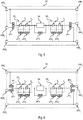
- Figures 7 and 8 show two embodiments of the electric connection of the printed circuit board shown in Figure 6 .
- Figure 7 shows the electric connection to implement a lighting module 20' V configured to be supplied with a regulated voltage V out provided via the terminals 200a and 200b.
- the means JP1 are configured to connect the positive terminal of the first LED string 22a to the terminal 200a.
- a link short-circuits the connector / electric contact JP1 a .
- the means JP4 are configured to connect the negative terminal of the last LED string 22b to the terminal 200b.
- a link short-circuits the connector / electric contact JP4 b .
- the LEDs L of the lighting module 20' V are connected in series between the terminals 200a and 200b.
- the printed circuit board also hosts the current regulator 24 connected in series with the LEDs L, i.e. the current regulator 24 is not bypassed.
- Module 20' V may therefore be used in the lighting system described with reference to Figure 1 , and the corresponding description is applicable thereto in its entirety.
- a plurality of lighting modules 20' V as shown in Figure 7 may be connected in parallel (see also Figure 1 ).
- Figure 9 shows a possible embodiment wherein a plurality of lighting modules 20' V , for example two modules 20' V1 and 20' V2 , are connected in parallel to an electronic converter 10 V , i.e. to a converter providing a regulated voltage V out .
- terminals 100a, 200a and 200c are denoted with "+” and the negative supply terminals 100b, 200b and 200d are denoted with "-”.
- terminals 200e and 200f have no additional sign.
- the electronic converter 10 V , the first lighting module 20 V1 and a second lighting module 20 V2 are connected to each other via cables.
- the terminals 100a and 100b of the electronic converter 10 V are implemented by way of rapid connection means, e.g. a screw or spring type terminal block, having e.g. two contacts.
- the electronic converter 10 V moreover includes two terminals 100d and 100e to be connected to a power source, e.g. the mains or a battery.
- a power source e.g. the mains or a battery.
- these terminals 100d and 100e may be implemented by means of a terminal block.
- terminals 200a, 200b, 200c, 200d, 200e and 200f of the lighting modules 20' V may be implemented by rapid connection means, for example screw or spring type terminal blocks, having e.g. three contacts which are soldered to respective contacts on the printed circuit board.
- the first lighting module 20 V1 (specifically the terminals 200a and 200b) is connected to the electronic converter 10 (specifically to the terminals 100a and 100b) by means of a first electric cable 50, having e.g. two wires.
- the second lighting module 20 V2 (specifically the terminals 200a and 200b) is connected to the first lighting module 20 V1 (specifically to the terminals 200c and 200d) by means of a first electric cable 52, having e.g. two wires.
- the terminals 200e and 200f are unused.
- Figure 10 shows an embodiment wherein the electric connection between a first lighting module 20 1 and a second lighting module 20 2 is already implemented during the production of the printed circuit board.
- one printed circuit board which includes one string of lighting modules 20'.
- the contacts 200c and 200a between two successive lighting modules 20' may be implemented by means of a single metallic zone.
- the contacts 200f and 200e, as well as 200d and 200b, may be implemented by means of respective metallic zones.
- the module string may be cut transversally along lines 60, in such a way as to sever again contacts 200c/200a, 200f/200e and 200d/200b between two successive lighting modules 20'.
- Figure 8 shows the electric connection for implementing a lighting module 20' C configured to be supplied with a regulated current i out provided through terminals 200a and 200b.
- the means JP1 are configured to connect the positive terminal of the first LED string 22a to the terminal 200a.
- a link short-circuits the connector / electric contact JP1 a .
- the means JP4 are configured to connect the negative terminal of the last LED string 22b to the terminal 200b.
- a link short-circuits the connector / electric contact JP4 b .
- the LEDs L of lighting module 20' C are connected in series between the terminals 200a and 200b.
- the current regulator 24 is not required, and the current regulator 24 (which in this case may not be mounted on the printed circuit board) is bypassed by means of a link which short-circuits the connector / electric contact JP3.
- the presently considered embodiment therefore connects the LEDs L of lighting module 20' C directly between the terminals 200a and 200b.
- the LEDs L of all the modules 20' C are preferably connected in series.
- the terminals 200e and 200f it is possible to use the terminals 200e and 200f.
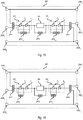
- Figures 11a and 11b show two lighting modules 20' C1 and 20' C2 .
- the module 20' C1 shown in Figure 11a substantially corresponds to the module described with reference to Figure 8 , the only difference being that the means JP4 are configured to connect the negative terminal of the last LED string 22b to the terminal 200f.
- a link short-circuits the connector / electric contact JP4 a .
- the module 20' C2 shown in Figure 11b substantially corresponds to the module described with reference to Figure 8 , the only difference being that the means JP1 are configured to connect the positive terminal of the first LED string 22a to the terminal 200e.
- a link short-circuits the connector / electric contact JP1 b .
- Figure 12a shows a possible connection of the lighting system as a whole.
- the first lighting module 20 C1 (specifically the terminals 200a and 200b) is connected to the electronic converter 10 (specifically to the terminals 100a and 100b) by means of a first electric cable 50, having e.g. two wires.
- the second lighting 20 C2 (specifically the terminals 200e and 200b) is connected to the first lighting module 20 V1 (specifically to the terminals 200f and 200d) by means of a first electric cable 52, having e.g. two wires.
- Figure 12b shows a second embodiment substantially corresponding to the embodiment shown in Figure 12a , the only difference consisting in the first lighting module 20 C1 being connected to the electronic converter 10 by using terminal 200e instead of terminal 200a.
- the means JP1 are therefore configured to connect the positive terminal of the first LED string 22a to terminal 200e, for example by means of a link which short-circuits the connector / electric contact JP1 b .
- the intermediate modules so that the means JP1 are configured to connect the positive terminal of the first LED string 22a to the terminal 200e, e.g. by means of a link which short-circuits the connector / electric contact JP1 b , and the means JP4 are configured to connect the negative terminal of the last LED string 22b to the terminal 200f, e.g. by means of a link which short-circuits the connector / electric contact JP4 a .
- the terminals 100e and 100f which enable a connection in series of the LEDs L of a plurality of modules 20' may be useful also in presence of a voltage driving.
- Figures 13a and 13b show two lighting modules 20' V1 and 20' V1 substantially having the same connection as shown with reference to Figures 11a e 11b, the only difference being that the current regulator 24 is implemented in one of both modules, e.g. in module 20' V1 .
- the LED strings 22a and 22b of both modules 20' V1 and 20' V1 and a single current regulator 24 are connected in series.
- the electronic converter 10 V should therefore also provide the double voltage V out .
- converter 10 V should provide a voltage of approximately 48 VDC.
- the means JP2 may be used in order to bypass, i.e. deactivate, one or more of the LEDs L, so that the voltage of the LEDs is lower than the voltage provided by the electronic converter 10 V .
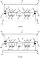
- FIG. 14a and 14b this is shown in Figures 14a and 14b , wherein the means JP2 are configured to bypass the LEDs L 2 and L 4 of both modules 20' V1 and 20' V1 .
- a link short-circuits the connectors / electric contacts JP4 2 and JP4 4 of both modules 20' V1 and 20' V1 .
- the respective LEDs L may not be mounted on the printed circuit board.
- This connection therefore modifies the number of LEDs which are activated in each lighting module 20', thereby also varying the LED pitch.
- the means JP2 may be used to adapt the voltage of each lighting module 20' V to the voltage provided by the electronic converter 10 V .
- said module may also be used with an electronic converter 10 V providing a voltage of 12 VDC.
- a lighting module 20' C i.e. with current driving, said means enable adapting the number of LEDs to the specific requirements.
- the means JP2 must not necessarily be configured so as to enable a deactivation of all the LEDs L.
- Figure 15 shows an embodiment wherein respectively two consecutive LEDs L 1 /L 2 and L 3 /L 4 have means JP 12 and JP 34 associated thereto which enable:
- Figure 16 shows an embodiment wherein some LEDs, e.g. LEDs L 2 and L 4 , are always active, while other LEDs, e.g. LEDs L 1 and L 3 may have respective means JP2 associated thereto.
- one or more LEDs L of the lighting module 20' have means JP2 associated thereto enabling a selective bypass of LED L.
- the means JP1-JP4 may be implemented also via other electric contacts between two electric contacts, such as e.g. two metallic zones on a printed circuit board which are not covered by the solder mask.
- electric connection substantially corresponds to a switch, and therefore may have two operating conditions:
- said connections may be normally open or closed.
- the circuit when the connection is normally open, the circuit includes two contacts which may be closed by means of a link, e.g. by using connectors, or by soldering the link directly onto the respective contacts of the printed circuit board.
- Figure 17 shows an embodiment wherein the means JP1-JP4 are implemented via (optionally zero-Ohm) resistors, which may be selectively attached to the printed circuit board.
- the printed circuit board includes metallic zones for mounting such resistors, even though the resistors are not necessarily mounted onto the printed circuit board.
- said metallic zones may have a shape according to a SMD format 1H (0201), 1E (0402), 1J (0603), 2A (0805) or 2B (1206).
- the printed circuit board when the connection is normally closed, the printed circuit board includes two contacts which are connected to each other via an electric trace on the printed circuit board, and the metallic material between both contacts may be removed or at least interrupted by means of an etching operation, e.g. by mechanical means or via a laser.
- an etching operation e.g. by mechanical means or via a laser.
- Figure 18 shows an embodiment having a bypass electric trace JP3 which therefore short-circuits the terminals of current regulator 24. If such a current regulator is required, the trace JP3 may be interrupted by etching.
- Figure 19 shows a corresponding method for implementing lighting modules 20'.
- step 1002 envisages designing the electric circuit of the lighting module 20' as described in the foregoing.
- the maximum number of LEDs is determined which the lighting modules may comprise, such as e.g. six LEDs L, i.e. one or more LED strings 22 are implemented.
- the respective selection means JP2 are chosen, i.e. for each LED L it is determined whether said LED includes bypass means JP2 and how such bypass means are implemented (normally open or closed; connector or only contacts, etc.).
- at least one LED of the lighting module 20' includes such a bypass, such as e.g. two contacts which may be short-circuited by means of an SMD, e.g. zero-Ohm, resistor.
- terminals 200a-200f of the lighting module 20' and the corresponding connection between the terminals 200a and 200c, and 200b and 200d are designed.
- the corresponding selection means JP1 and JP2 are designed which enable connecting the LEDs L to the terminals 200a-200f (see Figures 5 and 6 ) .
- a circuit of a current regulator 24, connected in series with the LEDs L, and the corresponding selection means JP3 are designed.
- said electric circuit may also envisage a connection in series of a plurality of lighting modules 20', i.e. a connection of the terminals 200c, 200d and 200f of a lighting module 20' to the terminals 200a, 200b and 200e of the previous lighting module 20' (if said module is not the first in the chain).
- step 1004 the corresponding printed circuit board is implemented on the basis of the electric circuit designed in step 1002.
- a printed circuit board which may include contacts and electric traces, in order to implement one or more lighting modules 20' connected in series. Therefore, the corresponding components must be soldered onto said printed circuit board in order to implement the lighting modules 20'.
- the first module of the printed circuit board is chosen, and the number of LEDs L is determined which said module is supposed to include. Subsequently, said LEDs L are soldered onto the printed circuit board, and optionally the selection means JP2 are set in order to bypass the connection terminals of unused LEDs (see for example Figures 14a and 14b ).
- a step 1008 it is determined whether said lighting module 20' is a single module or the first module in a chain.
- step 1010 envisages the setting of the means JP1 in such a way as to connect the positive terminal of the first LED string 22a to the positive terminal of the electronic converter 10, e.g. by short-circuiting the connectors / electric contacts JP1 a (or JP1 b as previously described with reference to the Figures 12a and 12b ).
- a subsequent step 1010 it is moreover determined whether the lighting module 20' is supplied with a regulated voltage or current.
- step 1014 the components of the current regulator 24 are mounted and the corresponding selection means JP3 are set so that the current regulator 24 is not bypassed.
- module 20' is supplied with a regulated current (result "C" of step 1012)
- the corresponding selection means JP3 are set in such a way as to bypass the electric contacts of the current regulator 24.
- module 20' is a following module in a module chain, i.e. if module 20' is neither a single module nor the first module of a chain (result "N" of step 1008), in a step 1020 the means JP1 are set in such a way as to connect the positive terminal of the first LED string 22a to the terminal 200e of module 20', e.g. by short-circuiting the connectors / electric contacts JP1 b .
- the current regulator 24 is activated only if the module is supplied with voltage and if said module is a single module or the first module in a chain. However, generally speaking, regulator 24 may also be activated in a following module of the chain.
- a further step 1018 involves determining the connection of the means JP4. Specifically, in step 1018, it is determined whether the lighting module 20' is a single module or the last module in a chain of lighting modules.
- step 1028 the means JP4 are set in such a way as to connect the negative terminal of the last string of LEDs 22b to the terminal 200f, e.g. by short-circuiting the connectors / electric contacts JP4 a .
- the method proceeds to the step 1006 for determining the configuration of the next/following lighting module 20' in the chain.
- the means JP4 are set in such a way as to connect the negative terminal of the last LED string 22b to the negative terminal of the electronic converter 10, i.e. to the terminal 200b, e.g. by short-circuiting the connectors / electric contacts JP4 b .
- a step 1024 may be envisaged wherein the printed circuit board is cut after the current lighting module 20', because said module 20' is a single module or the last module in a chain of lighting modules.
- the selection of the arrangement instead of performing said assembly step by step, the selection of the arrangement, the corresponding mounting of components and the optional separation of modules 20' may also be carried out one after the other.
- the LEDs of the various lighting modules 20' of a chain / string of lighting modules 20' as shown in Figure 10 are not necessarily connected in series. Indeed, as shown in Figures 20a and 20b , a first module 20' 1 may be configured so that the respective LEDs L are connected in series between the terminals 200e and 200b, and a second module 20' 2 may be configured so that the respective LEDs L are connected in series between the terminals 200a and 200b. Therefore, an electronic converter 10 providing two supply signals may provide the first supply signal to the terminal 200e of the first module 20' 1 , therefore supplying the LEDs of the first module 20' 1 . Moreover, the electronic converter 10 may provide the second supply signal to the terminal 200a of the first module 20' 1 , which is therefore also sent to terminal 200a of the second module 20' 2 , thereby supplying the LEDs L of the second module 20' 2 .
- this sort of driving may be used to regulate the colour of the light emitted by the system.
- the terminal 200c may also be omitted, because such a terminal has the main function of enabling a parallel connection of a plurality of LED strings (see Figure 9 ).
Landscapes
- Engineering & Computer Science (AREA)
- Microelectronics & Electronic Packaging (AREA)
- Manufacturing & Machinery (AREA)
- Circuit Arrangement For Electric Light Sources In General (AREA)
Abstract
- a first (200a), a second (200e) and a third positive terminal (200f),
- a first (200b) and a second (200d) negative terminal, wherein the second negative terminal (200d) is connected to the first negative terminal (200b), and
- electric contacts for the mounting of one or more LEDs (L) and electric traces such that the LEDs (L) are connected in series forming a LED string (22).
a) a connection of the LED string (22) between the first positive terminal (200a) and the third positive terminal (200f),
b) a connection of the LED string (22) between the first positive terminal (200a) and the first negative terminal (200b),
c) a connection of the LED string (22) between the second positive terminal (200a) and the third positive terminal (200f), and
d) a connection of the LED string (22) between the second positive terminal (200a) and the first negative terminal (200b).
Description
- The description relates to printed circuit boards for lighting modules and to corresponding lighting modules.
- A lighting system typically includes an
electronic converter 10 and at least onelighting module 20. - For example, the
electronic converter 10 may include an AC/DC or DC/DC switching supply, receiving at input a supply signal (e.g. from the mains or from a battery) and providing at output a regulated voltage Vout or a regulated current iout. - A
lighting module 20 includes one or more light radiation sources including e.g. at least one LED (Light Emitting Diode) or other solid-state lighting means such as e.g. laser diodes. - For example,
Figure 1 shows a system wherein the electronic converter is avoltage generator 10V and similarly thelighting modules 20 aremodules 20V configured to be supplied with a voltage. For example,Figure 1 shows twolighting modules - Therefore, in
Figure 1 , theelectronic converter 10V provides at output, via a positive terminal 100a and a negative terminal 100b, which represents a ground GND, a regulated voltage Vout . - For example,
Figure 2 shows an example of alighting module 20V configured to be supplied with a regulated voltage Vout . - Specifically,
lighting module 20V includes a positive input terminal 200a and a negative input terminal 200b, for the connection to the terminals 100a and 100b ofelectronic converter 10V. For example,lighting module 20V may be connected, via a cable C1, to theelectronic converter 10V. Therefore, terminal 200a is connected to terminal 100a, and terminal 200b is connected to terminal 100b, and therefore thelighting module 20 receives the voltage Vout . - In the presently considered example, the
lighting module 20V is a LED module including one or more LEDs L connected between the terminals 200a and 200b. For example,module 20V may include a LED chain orstring 22, wherein a plurality of LEDs is connected in series. Moreover, the LEDs L may also be distributed onto various branches connected in parallel. For example, as shown inFigure 2 ,module 20V may include afirst LED string 22a including a first set of LEDs connected in series, and a second LED string 22b including a second set of LEDs L connected in series. - As the
lighting module 20V is supplied with a voltage, thelighting module 20 includes acurrent regulator 24 connected in series with eachLED string 22. For example, inFigure 2 , thefirst LED string 22a and a firstcurrent regulator 24 are connected (e.g. directly) in series between the terminals 200a and 200b, and the second LED string 22b and a secondcurrent regulator 24 are connected (e.g. directly) in series between the terminals 200a and 200b. - Therefore, in the presently considered example, the
strings 22a and 22b are supplied with a common voltage (Vout ). In this case, theLED strings 22 with the respectivecurrent regulators 24 included in thevarious lighting modules 20V should be connected in parallel at the voltage Vout provided by theelectronic converter 10V. As a consequence, also thelighting modules 20V should be electrically connected in parallel to voltage Vout . - For example, in
Figures 1 and 2 , thelighting module 20V1 also includes apositive output terminal 200c and a negative output terminal 200d, for the connection to a following lighting module, forexample module 20V2. Specifically, saidterminals 200c/200d are connected (e.g. directly) to the terminals 200a/200b. Therefore, the voltage (Vout ) received at the terminals 200a and 200b is also applied to theterminals 200c and 200d. - Therefore, the terminals 200a and 200b of the
lighting module 20V2 may be connected (directly or via a cable C2) to the terminals 100a and 100b of theelectronic converter 10V, or to theterminals 200c and 200d of thelighting module 20V1, which again provide the voltage Vout . As a consequence, althoughmodules - In the simplest instance, the
current regulator 24 may be a resistor or a linear current regulator. Thecurrent regulator 24 may also be implemented by means of current mirrors or a switched mode current source regulator, typically including an inductor and an electronic switch. - On the other hand,
Figure 3 shows a system wherein the electronic converter is acurrent generator 10C, and similarly thelighting modules 20 aremodules 20C configured to be supplied with a current. For example,Figure 3 shows twolighting modules - Therefore, in
Figure 3 , theelectronic converter 10C provides at output via the positive terminal 100a and the negative terminal 100b, which again represents a ground GND, a regulated current iout . - With a regulated current, the LEDs L distributed throughout the
various lighting modules 20 are connected in series between the terminals 100a and 100b. - Generally speaking, also in this case, each
lighting module 20C includes two terminals 200a and 200b. For example, if only onesingle lighting module 20C may be connected to theelectronic converter 10C, the LEDs L of said module are connected in series between the terminals 200a and 200b. - On the other hand, in
Figure 3 , a plurality oflighting modules 20C may be connected to converter 10C. In this case, eachlighting module 20C moreover includes twoterminals 200c and 200d for the connection to the terminals 200a and 200b of a followinglighting module 20C. In this case, theterminals 200c and 200d of thelast lighting module 20C, forexample module 20C2, are short-circuited (internally or externally) to close the current path. As regards such a connection, mention may be made ofdocument EP 2 805 101 , the content whereof is incorporated herein by way of reference. - In this case, as shown in
Figure 4 , the LEDs L of each lighting module 20c may be connected in series between theterminals 200a and 200c and/or between the terminals 200d and 200b. - For example, in the presently considered embodiments, two
LED strings 22a and 22b are connected in series between theterminals 200a and 200c, and terminal 200d is connected (e.g. directly) to terminal 200b. - Generally speaking, also in this case, a plurality of LED strings may be connected in parallel, optionally having a resistor connected in series in order to improve the current distribution among the various strings. The person skilled in the art will appreciate that this solution is rather basic, because if LED strings are added or removed it is necessary to adapt the current provided by the electronic converter.
- Therefore, the
lighting modules 20 have a structure which changes as a function of the envisaged supply (voltage or current supply). Moreover, according to the needs, eachlighting module 20 may include a different number of LEDs. - Consequently, in order to improve the characteristics of a
lighting module 20, in particular as regards efficiency, light emission and LED pitch, thelighting module 20 must be designed specifically. For example, the designer must choose the correct LEDs, e.g. as regards spectral characteristic (colour) and brightness, and he must design a rigid or a flexible printed circuit board. While designing said printed circuit board, the designer must also take into account the electric configuration of the circuit (current or voltage driving) and the sizing specifications of the printed circuit board. - Therefore, these parameters must be taken into account each time the requirements vary, leading to the need of developing a different lighting module for each new application. As a consequence, also the designed printed circuit boards will be different from each other, which increases the manufacturing and storage cost of the printed circuit boards.
- However, solutions are known which enable a partial re-use of the printed circuit boards of other products. For example, with reference to
Figure 2 , the LEDs L of amodule 20V may easily be replaced with LEDs of a different colour. Moreover, the brightness ofmodule 20V may be varied, by modifying the current flowing through theLED string 22, e.g. by adaptingcurrent regulator 24 e.g. by modifying the reference resistor of a corresponding current regulator. - Also the
lighting modules 20C with current supply may be re-used. For example,document EP 2 805 101 A1 shows LED modules which may be cut to different lengths. However, in case of a change of the supply current for thelighting modules 20C, theelectronic converter 10C must be adapted. - The present description aims at providing solutions for implementing rigid or flexible printed circuit boards for lighting modules which may be re-used more easily.
- According to one or more embodiments, said object is achieved thanks to a printed circuit board having the features set forth in the claims that follow. The claims also concern a corresponding lighting module, lighting system and method for implementing lighting modules.
- The claims are an integral part of the technical teaching provided herein with reference to the invention.
- As mentioned in the foregoing, various embodiments of the present specification concern a printed circuit board for a lighting module.
- In various embodiments, the printed circuit board includes metallic zones including a first positive terminal and a first negative terminal, typically used for the connection to an electronic converter. In various embodiments, the metallic zones also include a second positive terminal, which may be used for connecting the respective lighting module to a previous module. Moreover, the metallic zones may include a third positive terminal and a second negative terminal (connected via an electric trace to the first negative terminal) which may be used for connecting the respective lighting module to a following module. In various embodiments, the printed circuit board may include a fourth positive terminal, connected (via an electric trace to the first negative terminal) to the first positive terminal. For example, this terminal may be useful if a plurality of lighting modules are connected in parallel to the electronic converter.
- In various embodiments, the metallic zones moreover include electric contacts for mounting one or more LEDs, and electric traces between these contacts, so that the LEDs are connected in series by forming a LED string.
- In various embodiments, the printed circuit board includes selection means, implemented by means of electric traces and metallic contacts adapted to be short-circuited via links, so as to enable all the following connections:
- a) a connection of the LED string between the first positive terminal and the third positive terminal,
- b) a connection of the LED string between the first positive terminal and the first negative terminal,
- c) a connection of the LED string between the second positive terminal and the third positive terminal, and
- d) a connection of the LED string between the second positive terminal and the first negative terminal.
- Therefore, the selection means enable configuring the lighting module either as a single module or as the first, intermediate or last module of a chain of modules.
- For example, in various embodiments, it is determined whether the lighting module is a single lighting module or if it belongs to a string of lighting modules.
- If the lighting module is a single lighting module, the selection means are set so that the LED string is connected between the first positive terminal and the first negative terminal, alternatively between the second positive terminal and the first negative terminal.
- On the contrary, if the lighting module belongs to a string of lighting modules, it is determined (at least) whether the lighting module is the first or the last lighting module of the string of lighting modules. If the lighting module is the first lighting module of the string of lighting modules, the selection means are set so that the LED string is connected between the first positive terminal and the third positive terminal, or alternatively between the second positive terminal and the third positive terminal. On the other hand, if the lighting module is the last lighting module of the string of lighting modules, the selection means are set so that the LED string is connected between the second positive terminal and the first negative terminal. Finally, if the lighting module is an intermediate module of the string of lighting modules, the selection means are set so that the LED string is connected between the second positive terminal and the third positive terminal.
- In various embodiments, the selection means may include:
- a first set of two contacts, connected via electric traces between the first positive terminal and the positive terminal of the LED string;
- a second set of two contacts, connected via electric traces between the second positive terminal and the positive terminal of the LED string;
- a third set of two contacts, connected via electric traces between the negative terminal of the LED string and the third positive terminal; and
- a fourth set of two contacts, connected via electric traces between the negative terminal of the LED string and the first negative terminal.
- For example, in various embodiments, both contacts of said sets are metallic contacts having a SMD format 1H/0201, 1E/0402, 1J/0603, 2A/0805 or 2B/1206.
- Therefore, in various embodiments, the lighting module includes a printed circuit board, wherein one or more LEDs are mounted on the printed circuit board. Moreover, both contacts of the first set or alternatively of the second set are closed via a link, and both contacts of the third set or alternatively of the fourth set are closed via a link.
- In various embodiments, the printed circuit board includes bypass means, implemented by means of electric traces, and/or metallic contacts configured to be short-circuited, in order to selectively bypass one or more of the LEDs.
- In various embodiments, the printed circuit board may include electric contacts for mounting or implementing a current regulator, and further bypass means implemented by means of electric traces and/or metallic contacts, configured to be short-circuited in order to selectively bypass the current regulator. For example, said regulator and the respective bypass means may be used in order to implement lighting modules which may be supplied with a regulated voltage or alternatively with a regulated current.
- Embodiments will now be described, by way of non-limiting example only, with reference to the annexed Figures, wherein:
-
Figures 1 to 4 have already been described in the foregoing, -
Figure 5 shows a fist embodiment of the electric circuit of a printed circuit board of a lighting module according to the present specification; -
Figure 6 shows a second embodiment of the electric circuit of a printed circuit board of a lighting module according to the present specification; -
Figure 7 shows a first embodiment of the arrangement of the electric circuit ofFigure 6 , so as to implement a lighting module adapted to be supplied with a voltage; -
Figure 8 shows a second embodiment of the arrangement of the electric circuit ofFigure 6 , so as to implement a lighting module adapted to be supplied with a current; -
Figure 9 shows an embodiment of the connection of a plurality of lighting modules with an electronic converter, configured to provide a regulated voltage; -
Figure 10 shows an embodiment of a printed circuit board including a plurality of lighting modules connected in cascade; -
Figures 11a and 11b show an embodiment of the arrangement of the electric circuit ofFigure 6 , in order to implement lighting modules connected in cascade; -
Figures 12a and 12b show an embodiment of the connection of a plurality of lighting modules to an electronic converter configured to provide a regulated current; -
Figures 13a, 13b ,14a and 14b show various embodiments of the arrangement of the electric circuit ofFigure 6 , in order to implement lighting modules connected in cascade; -
Figures 15, 16 ,17 and 18 show further embodiments of the electric circuit of a printed circuit board of a lighting module according to the present specification; -
Figure 19 shows an embodiment of a method for implementing lighting modules; and -
Figures 20a and 20b show a further embodiment of the arrangement of the electric circuit ofFigure 6 . - In the following description, various specific details are given to provide a thorough understanding of the embodiments. The embodiments may be practiced without one or several specific details, or with other methods, components, materials, etc. In other instances, well-known structures, materials, or operations are not shown or described in detail in order to avoid obscuring various aspects of the embodiments.
- Reference throughout this specification to "one embodiment" or "an embodiment" means that a particular feature, structure, or characteristic described in connection with the embodiment is included in at least one embodiment. Thus, the possible appearances of the phrases "in one embodiment" or "in an embodiment" in various places throughout this specification are not necessarily all referring to the same embodiment. Furthermore, particular features, structures, or characteristics may be combined in any suitable manner in one or more embodiments.
- The headings provided herein are for convenience only, and therefore do not interpret the extent of protection or scope of the embodiments.
- In the following
Figures 5 to 20 , the parts, the elements or the components which have already been described with reference to theFigures 1 to 4 are denoted with the same references previously used in said Figures; the description of said previously described elements will not be repeated in the following in order not to overburden the present detailed description. - As mentioned in the foregoing, the present description provides solutions for implementing printed circuit boards which may be used for different lighting modules.
- For example, various embodiments enable the implementation of printed circuit boards having one or more of the following advantages:
- a variable number of LEDs may be mounted onto the printed circuit board, thereby varying the LED pitch, i.e. the distance between two successive LEDs;
- the same printed circuit board may be used in order to implement lighting modules with voltage or current supply;
- the same printed circuit board may be used with different supply voltages, e.g. 12 VDC, 24 VDC o 48 VDC.
- In various embodiments, the advantages mentioned in the foregoing may be achieved by a single printed circuit board, which may be reconfigured. For example, in various embodiments, some electric connections may be enabled selectively via jumpers or by soldering resistors or bridges / wire links, such as zero-Ohm resistors, onto the printed circuit board.
- In various embodiments, the same printed circuit board may therefore be used in order to implement:
-
supply modules 20V configured to be supplied with a given voltage, e.g. 24 VDC, and having a given number of LEDs, e.g. six LEDs, considering the typical junction voltages of white LEDs; -
lighting modules 20V configured to be supplied with the same voltage and having half the number of LEDs mounted; -
lighting modules 20V configured to be supplied with a higher voltage, e.g. 48 VDC; -
lighting modules 20V configured to be supplied with a lower voltage, e.g. 12 VDC; -
lighting modules 20C configured to be supplied with a constant current, also enabling the implementation of chains oflighting modules 20C; -
lighting modules 20C configured to be supplied with a constant current, also enabling a parallel connection of a plurality of chains of supply modules 20c. - Moreover, various embodiments may also be employed for solutions wherein the light emitted by two LED strings (distributed on one or more LED modules) may be adjusted (so-called dimming) independently, therefore leading to the implementation of systems wherein the colour of the emitted light may be varied. For example, if the emitted light is always white, such systems are typically known as "tunable white LED system".
-
Figure 5 shows a first embodiment of the electric arrangement of the printed circuit board of a lighting module 20' according to the present specification. - In the presently considered embodiment, the printed circuit board / lighting module 20' includes six terminals 200a-200f. Specifically, the positive terminal 100a and the negative terminal 100b, representing a ground, enable the reception of a supply signal from an
electronic converter 10. On the other hand, the positive terminal 100c and the negative terminal 100d may be used for providing said supply signal to another lighting module 20'. For this purpose, the positive terminal 100c is connected (within module 20' and e.g. directly via electric traces) to terminal 100a, and the negative terminal 100d is connected (within module 20' and e.g. directly via electric traces) to terminal 100b. The terminals 100e and 100f enable a connection in series of a plurality of modules 20', and the operation of said terminals will be described in the following. - In the presently considered embodiment, module 20' includes a plurality of light radiation sources L, such as e.g. LEDs or other solid-state lighting means, i.e. the printed circuit board includes contacts for mounting said LEDs L. For example, in the presently considered embodiment, module 20' includes four LEDs L1, L2, L3 and L1. Generally speaking, said LEDs L may be distributed in one or more LED strings 22. Therefore, generally speaking, lighting module 20' includes one or more LED strings 22, and each
LED string 22 includes one or more LEDs L which are connected (e.g. directly) in series, i.e. the printed circuit board includes electric traces configured so that the LEDs L are connected in series. For example, inFigure 5 , module 20' includes afirst LED string 22a including two LEDs L1 and L2 connected in series, and asecond LED string 22b including two LEDs L3 and L4 connected in series. For example, in various embodiments, each lighting module 20' employs a printed circuit board enabling mounting six LEDs L, which may be distributed instrings 22a and 22b. - In various embodiments, the printed circuit board / lighting module 20' includes selection means JP1 and JP4, which enable four different connections of the LED string(s) 22 to the terminals 200a-200f of the lighting module 20'.
- Specifically, said means enable the following connections:
- a connection in series of the LED string (s) 22 between terminal 200a and terminal 200f,
- a connection in series of the LED string (s) 22 between terminal 200a and terminal 200b or terminal 200d,
- a connection in series of the LED string (s) 22 between terminal 200e and terminal 200f, and
- a connection in series of the LED string (s) 22 between terminal 200e and terminal 200b or terminal 200d.
- For example, in the presently considered embodiment, the means are implemented via connectors JP3 and JP4 which may be short-circuited via so-called jumpers. For example, the connectors may be so-called "pin header strips", i.e. strips including pins. As will be described in the following, such configuration / selection connectors may also be implemented via other electric contacts on the printed circuit board, i.e. metallic zones which are not covered by the so-called "solder mask", which may be short-circuited via jumpers which are soldered onto the printed circuit board. Typically, said jumpers are generally denoted as links or wire links, and the term jumper is normally used in the context of connectors (so-called jumper blocks).
- Specifically, the presently considered embodiment employs a first connector with three contacts JP3, wherein the central contact is connected to the positive terminal of the first LED string, e.g. to the anode of diode L1. On the other hand, the external contacts are connected (e.g. directly) respectively to terminal 200a and to terminal 200e. Therefore, a simple link may be used to connect the positive terminal of the first LED string to terminal 200a or to terminal 200e.
- Similarly, it is possible to resort to a second connector having three contacts JP4, the central contact whereof is connected to the negative terminal of the last LED string, e.g. to the cathode of diode L4. On the other hand, the external contacts are connected (e.g. directly) respectively to terminal 200f and to terminal 200d. Therefore, a simple link may be used for connecting the negative terminal of the last LED string to terminal 200f or to terminal 200d.
- On the other hand,
Figure 6 shows an embodiment wherein the connector JP1 and/or the connector JP4 having three contacts ofFigure 5 have been replaced respectively with two connectors with two contacts JP1a/JP1b and JP4a/JP4b. - Therefore, also in this case, a link may be used to connect the positive terminal of the first LED string to terminal 200a (by short-circuiting connector JP1a) or to terminal 200e (by short-circuiting connector JP1b). Similarly, a link may be used to connect the negative terminal of the last LED string to terminal 200f (by short-circuiting connector JP4a) or to terminal 200d (by short-circuiting connector JP4b).
- In various embodiments, each
LED string 22 and/or each LED L may have means JP2 associated thereto in order to bypass, i.e. short-circuit, therespective LED string 22 or the respective LED L. - For example, in the
Figures 5 and 6 , each LED L1, L2, L3 and L4 has, connected in parallel thereto, a connector having two contacts JP21, JP22, JP23 and JP24, which therefore may be closed via a link, thereby bypassing the respective LED L. For example, these connectors JP2 may be employed to bypass the connection terminals on a printed circuit board, if the respective LED is not mounted on the printed circuit board. - In various embodiments, a
current regulator 24 may be connected in series with the LED string(s) 22, i.e. the printed circuit board includes the contacts and optionally the respective electric traces, for mounting or implementing acurrent regulator 24. For example, in the presently considered embodiment, thecurrent regulator 24 is connected between thefirst LED string 22a and thesecond LED string 22b. Therefore, in various embodiments, the lighting module 20' includes one ormore LED strings 22 and acurrent regulator 24, which are connected (e.g. directly) in series. - Generally speaking, also said
regulator 24 may have means JP3 associated thereto for bypassing, i.e. short-circuiting, thecurrent regulator 24. - For example, in the
Figures 5 and 6 ,regulator 24 has, connected in parallel thereto, a connector having two contacts JP3, which therefore may be closed via a link, therefore bypassingregulator 24. For example, this connector JP3 may be used for bypassing the connection terminals on a printed circuit board, if thecurrent regulator 24 is not required. - Therefore, in the presently considered embodiments, connectors / electric contacts and links are used in order to modify the electric connection of the LEDs L and optionally of the
current regulator 24 with respect to the terminals 200a-200f. - For example,
Figures 7 and 8 show two embodiments of the electric connection of the printed circuit board shown inFigure 6 . - Specifically,
Figure 7 shows the electric connection to implement a lighting module 20'V configured to be supplied with a regulated voltage Vout provided via the terminals 200a and 200b. - Therefore, in the presently considered embodiment, the means JP1 are configured to connect the positive terminal of the
first LED string 22a to the terminal 200a. For example, in the presently considered embodiment, a link short-circuits the connector / electric contact JP1a. Similarly, the means JP4 are configured to connect the negative terminal of the last LED string 22b to the terminal 200b. For example, in the presently considered embodiment, a link short-circuits the connector / electric contact JP4b. - Therefore, in the presently considered embodiment, the LEDs L of the lighting module 20'V are connected in series between the terminals 200a and 200b. As described with reference to
Figure 2 , in this case the printed circuit board also hosts thecurrent regulator 24 connected in series with the LEDs L, i.e. thecurrent regulator 24 is not bypassed. - Module 20'V may therefore be used in the lighting system described with reference to
Figure 1 , and the corresponding description is applicable thereto in its entirety. - Generally speaking, also a plurality of lighting modules 20'V as shown in
Figure 7 may be connected in parallel (see alsoFigure 1 ). - For example,
Figure 9 shows a possible embodiment wherein a plurality of lighting modules 20'V, for example two modules 20'V1 and 20'V2, are connected in parallel to anelectronic converter 10V, i.e. to a converter providing a regulated voltage Vout . - Specifically, the
positive supply terminals 100a, 200a and 200c are denoted with "+" and the negative supply terminals 100b, 200b and 200d are denoted with "-". On the contrary, terminals 200e and 200f have no additional sign. - Specifically, in the presently considered embodiment, the
electronic converter 10V, thefirst lighting module 20V1 and asecond lighting module 20V2 are connected to each other via cables. - For example, in the presently considered embodiment, the terminals 100a and 100b of the
electronic converter 10V are implemented by way of rapid connection means, e.g. a screw or spring type terminal block, having e.g. two contacts. As previously stated, theelectronic converter 10V moreover includes two terminals 100d and 100e to be connected to a power source, e.g. the mains or a battery. For example, also these terminals 100d and 100e may be implemented by means of a terminal block. - Similarly, also the
terminals 200a, 200b, 200c, 200d, 200e and 200f of the lighting modules 20'V may be implemented by rapid connection means, for example screw or spring type terminal blocks, having e.g. three contacts which are soldered to respective contacts on the printed circuit board. - Therefore, in the presently considered embodiment, the first lighting module 20V1 (specifically the terminals 200a and 200b) is connected to the electronic converter 10 (specifically to the terminals 100a and 100b) by means of a first
electric cable 50, having e.g. two wires. Moreover, the second lighting module 20V2 (specifically the terminals 200a and 200b) is connected to the first lighting module 20V1 (specifically to theterminals 200c and 200d) by means of a firstelectric cable 52, having e.g. two wires. - Therefore, in the presently considered embodiment, the terminals 200e and 200f are unused.
- On the other hand,
Figure 10 shows an embodiment wherein the electric connection between afirst lighting module 201 and asecond lighting module 202 is already implemented during the production of the printed circuit board. - Specifically, in the presently considered embodiment only one printed circuit board is implemented which includes one string of lighting modules 20'. In this case, the
contacts 200c and 200a between two successive lighting modules 20' may be implemented by means of a single metallic zone. Similarly, the contacts 200f and 200e, as well as 200d and 200b, may be implemented by means of respective metallic zones. - Therefore, said terminals are already connected, and the module string may be cut transversally along
lines 60, in such a way as to sever againcontacts 200c/200a, 200f/200e and 200d/200b between two successive lighting modules 20'. - On the other hand,
Figure 8 shows the electric connection for implementing a lighting module 20'C configured to be supplied with a regulated current iout provided through terminals 200a and 200b. - As a consequence, in the presently considered embodiment, the means JP1 are configured to connect the positive terminal of the
first LED string 22a to the terminal 200a. For example, in the presently considered embodiment, a link short-circuits the connector / electric contact JP1a. Similarly, the means JP4 are configured to connect the negative terminal of the last LED string 22b to the terminal 200b. For example, in the presently considered embodiment, a link short-circuits the connector / electric contact JP4b. - Therefore, in the presently considered embodiment, the LEDs L of lighting module 20'C are connected in series between the terminals 200a and 200b. As previously described, in this case, the
current regulator 24 is not required, and the current regulator 24 (which in this case may not be mounted on the printed circuit board) is bypassed by means of a link which short-circuits the connector / electric contact JP3. - The presently considered embodiment therefore connects the LEDs L of lighting module 20'C directly between the terminals 200a and 200b.
- However, if a plurality of lighting modules 20'C are supplied with the same current iout , the LEDs L of all the modules 20'C are preferably connected in series. For this purpose it is possible to use the terminals 200e and 200f.
- Specifically,
Figures 11a and 11b show two lighting modules 20'C1 and 20'C2. - Specifically, the module 20'C1 shown in
Figure 11a substantially corresponds to the module described with reference toFigure 8 , the only difference being that the means JP4 are configured to connect the negative terminal of the last LED string 22b to the terminal 200f. For example, in the presently considered embodiment, a link short-circuits the connector / electric contact JP4a. - On the other hand, the module 20'C2 shown in
Figure 11b substantially corresponds to the module described with reference toFigure 8 , the only difference being that the means JP1 are configured to connect the positive terminal of thefirst LED string 22a to the terminal 200e. For example, in the presently considered embodiment, a link short-circuits the connector / electric contact JP1b. - For example,
Figure 12a shows a possible connection of the lighting system as a whole. - Specifically, in the presently considered embodiment, the first lighting module 20C1 (specifically the terminals 200a and 200b) is connected to the electronic converter 10 (specifically to the terminals 100a and 100b) by means of a first
electric cable 50, having e.g. two wires. Moreover, the second lighting 20C2 (specifically the terminals 200e and 200b) is connected to the first lighting module 20V1 (specifically to the terminals 200f and 200d) by means of a firstelectric cable 52, having e.g. two wires. - On the other hand,
Figure 12b shows a second embodiment substantially corresponding to the embodiment shown inFigure 12a , the only difference consisting in thefirst lighting module 20C1 being connected to theelectronic converter 10 by using terminal 200e instead of terminal 200a. In this case, the means JP1 are therefore configured to connect the positive terminal of thefirst LED string 22a to terminal 200e, for example by means of a link which short-circuits the connector / electric contact JP1b. - Generally speaking, also in this case only one printed circuit board might be used, which again includes a string of modules 20' as shown with reference to
Figure 10 , be re-arranging the electric connection thereof. - Generally speaking, even more than two modules 20'C may be connected in series. In this case it is only necessary to configure the intermediate modules so that the means JP1 are configured to connect the positive terminal of the
first LED string 22a to the terminal 200e, e.g. by means of a link which short-circuits the connector / electric contact JP1b, and the means JP4 are configured to connect the negative terminal of the last LED string 22b to the terminal 200f, e.g. by means of a link which short-circuits the connector / electric contact JP4a. - The terminals 100e and 100f which enable a connection in series of the LEDs L of a plurality of modules 20' may be useful also in presence of a voltage driving.
- For example,
Figures 13a and 13b show two lighting modules 20'V1 and 20'V1 substantially having the same connection as shown with reference toFigures 11a e 11b, the only difference being that thecurrent regulator 24 is implemented in one of both modules, e.g. in module 20'V1. - Therefore, in the presently considered embodiment, the LED strings 22a and 22b of both modules 20'V1 and 20'V1 and a single
current regulator 24 are connected in series. By resorting to such a connection, theelectronic converter 10V should therefore also provide the double voltage Vout . For example, if each of the modules 20'V1 and 20'V1 includes six LEDs,converter 10V should provide a voltage of approximately 48 VDC. - On the other hand, if
converter 10V provides a lower voltage, the means JP2 may be used in order to bypass, i.e. deactivate, one or more of the LEDs L, so that the voltage of the LEDs is lower than the voltage provided by theelectronic converter 10V. - For example, this is shown in
Figures 14a and 14b , wherein the means JP2 are configured to bypass the LEDs L2 and L4 of both modules 20'V1 and 20'V1. For example, in the presently considered embodiment, a link short-circuits the connectors / electric contacts JP42 and JP44 of both modules 20'V1 and 20'V1. In this case, the respective LEDs L may not be mounted on the printed circuit board. - This connection therefore modifies the number of LEDs which are activated in each lighting module 20', thereby also varying the LED pitch.
- Therefore, the means JP2 may be used to adapt the voltage of each lighting module 20'V to the voltage provided by the
electronic converter 10V. For example, by bypassing some given LEDs in the lighting module 20'V shown inFigure 7 , said module may also be used with anelectronic converter 10V providing a voltage of 12 VDC. - On the contrary, in a lighting module 20'C, i.e. with current driving, said means enable adapting the number of LEDs to the specific requirements.
- Generally speaking, the means JP2 must not necessarily be configured so as to enable a deactivation of all the LEDs L.
- For example,
Figure 15 shows an embodiment wherein respectively two consecutive LEDs L1/L2 and L3/L4 have means JP12 and JP34 associated thereto which enable: - the activation of both LEDs L1/L2 and L3/L4;
- the activation of the first LED L1 or L3; or
- the activation of the second LED L2 or L4.
- On the other hand,
Figure 16 shows an embodiment wherein some LEDs, e.g. LEDs L2 and L4, are always active, while other LEDs, e.g. LEDs L1 and L3 may have respective means JP2 associated thereto. - Therefore, generally speaking, one or more LEDs L of the lighting module 20' according to the present description have means JP2 associated thereto enabling a selective bypass of LED L.
- As mentioned in the foregoing, the means JP1-JP4 may be implemented also via other electric contacts between two electric contacts, such as e.g. two metallic zones on a printed circuit board which are not covered by the solder mask. Specifically, such electric connection substantially corresponds to a switch, and therefore may have two operating conditions:
- a first condition wherein the electric connection between both contacts is closed; and
- a second condition wherein the electric connection between both contacts is interrupted.
- Therefore, generally speaking, said connections may be normally open or closed.
- Specifically, when the connection is normally open, the circuit includes two contacts which may be closed by means of a link, e.g. by using connectors, or by soldering the link directly onto the respective contacts of the printed circuit board.
- For example,
Figure 17 shows an embodiment wherein the means JP1-JP4 are implemented via (optionally zero-Ohm) resistors, which may be selectively attached to the printed circuit board. As a consequence, the printed circuit board includes metallic zones for mounting such resistors, even though the resistors are not necessarily mounted onto the printed circuit board. For example, said metallic zones may have a shape according to a SMD format 1H (0201), 1E (0402), 1J (0603), 2A (0805) or 2B (1206). - On the other hand, when the connection is normally closed, the printed circuit board includes two contacts which are connected to each other via an electric trace on the printed circuit board, and the metallic material between both contacts may be removed or at least interrupted by means of an etching operation, e.g. by mechanical means or via a laser. For example, this applies to electric traces which may be interrupted e.g. by laser etching.
- For example,
Figure 18 shows an embodiment having a bypass electric trace JP3 which therefore short-circuits the terminals ofcurrent regulator 24. If such a current regulator is required, the trace JP3 may be interrupted by etching. -
Figure 19 shows a corresponding method for implementing lighting modules 20'. - After a
starting step 1000,step 1002 envisages designing the electric circuit of the lighting module 20' as described in the foregoing. - Specifically, in various embodiments the maximum number of LEDs is determined which the lighting modules may comprise, such as e.g. six LEDs L, i.e. one or
more LED strings 22 are implemented. Moreover, as described e.g. with reference toFigures 5, 6 ,15, 16 ,17 and 18 , for each LED L the respective selection means JP2 are chosen, i.e. for each LED L it is determined whether said LED includes bypass means JP2 and how such bypass means are implemented (normally open or closed; connector or only contacts, etc.). Specifically, in various embodiments, at least one LED of the lighting module 20' includes such a bypass, such as e.g. two contacts which may be short-circuited by means of an SMD, e.g. zero-Ohm, resistor. - Moreover, the terminals 200a-200f of the lighting module 20' and the corresponding connection between the
terminals 200a and 200c, and 200b and 200d are designed. Moreover, the corresponding selection means JP1 and JP2 are designed which enable connecting the LEDs L to the terminals 200a-200f (seeFigures 5 and 6 ) . - In various embodiments, there is moreover provided a circuit of a
current regulator 24, connected in series with the LEDs L, and the corresponding selection means JP3 are designed. - As shown with reference to
Figure 10 , said electric circuit may also envisage a connection in series of a plurality of lighting modules 20', i.e. a connection of theterminals 200c, 200d and 200f of a lighting module 20' to the terminals 200a, 200b and 200e of the previous lighting module 20' (if said module is not the first in the chain). - In a
step 1004, the corresponding printed circuit board is implemented on the basis of the electric circuit designed instep 1002. - Therefore, after step 1004 a printed circuit board is provided which may include contacts and electric traces, in order to implement one or more lighting modules 20' connected in series. Therefore, the corresponding components must be soldered onto said printed circuit board in order to implement the lighting modules 20'.
- For example, in a
step 1006, the first module of the printed circuit board is chosen, and the number of LEDs L is determined which said module is supposed to include. Subsequently, said LEDs L are soldered onto the printed circuit board, and optionally the selection means JP2 are set in order to bypass the connection terminals of unused LEDs (see for exampleFigures 14a and 14b ). - In a
step 1008, it is determined whether said lighting module 20' is a single module or the first module in a chain. - If the lighting module 20' is a single module or the first module in a chain (result "Y" in step 1008),
step 1010 envisages the setting of the means JP1 in such a way as to connect the positive terminal of thefirst LED string 22a to the positive terminal of theelectronic converter 10, e.g. by short-circuiting the connectors / electric contacts JP1a (or JP1b as previously described with reference to theFigures 12a and 12b ). - In a
subsequent step 1010, it is moreover determined whether the lighting module 20' is supplied with a regulated voltage or current. - If the lighting module 20' is supplied with a regulated voltage (result "V" of step 1012), in a
step 1014 the components of thecurrent regulator 24 are mounted and the corresponding selection means JP3 are set so that thecurrent regulator 24 is not bypassed. - On the other hand, if module 20' is supplied with a regulated current (result "C" of step 1012), the corresponding selection means JP3 are set in such a way as to bypass the electric contacts of the
current regulator 24. - On the other hand, if module 20' is a following module in a module chain, i.e. if module 20' is neither a single module nor the first module of a chain (result "N" of step 1008), in a
step 1020 the means JP1 are set in such a way as to connect the positive terminal of thefirst LED string 22a to the terminal 200e of module 20', e.g. by short-circuiting the connectors / electric contacts JP1b. - Therefore, in the presently considered embodiment, the
current regulator 24 is activated only if the module is supplied with voltage and if said module is a single module or the first module in a chain. However, generally speaking,regulator 24 may also be activated in a following module of the chain. - At the end of the
steps further step 1018 involves determining the connection of the means JP4. Specifically, instep 1018, it is determined whether the lighting module 20' is a single module or the last module in a chain of lighting modules. - If lighting module 20' is not a single module or the last module in a chain (result "N" of step 1018), in a
step 1028 the means JP4 are set in such a way as to connect the negative terminal of the last string of LEDs 22b to the terminal 200f, e.g. by short-circuiting the connectors / electric contacts JP4a. Moreover, the method proceeds to thestep 1006 for determining the configuration of the next/following lighting module 20' in the chain. - On the other hand, if the lighting module 20' is a single module or the last module of a chain (result "Y" of step 1018), in a
step 1022 the means JP4 are set in such a way as to connect the negative terminal of the last LED string 22b to the negative terminal of theelectronic converter 10, i.e. to the terminal 200b, e.g. by short-circuiting the connectors / electric contacts JP4b. - If the lighting modules in the chain are mounted on the same printed circuit board, a
step 1024 may be envisaged wherein the printed circuit board is cut after the current lighting module 20', because said module 20' is a single module or the last module in a chain of lighting modules. - Finally, the process ends at an
end step 1026. - Generally speaking, instead of performing said assembly step by step, the selection of the arrangement, the corresponding mounting of components and the optional separation of modules 20' may also be carried out one after the other.
- The presently described solutions enable therefore the implementation of single lighting modules or of chains of lighting modules (which are connected via cables or are placed on one and the same printed circuit board) which may be supplied with a regulated voltage or current.
- Generally speaking, the LEDs of the various lighting modules 20' of a chain / string of lighting modules 20' as shown in
Figure 10 are not necessarily connected in series. Indeed, as shown inFigures 20a and 20b , a first module 20'1 may be configured so that the respective LEDs L are connected in series between the terminals 200e and 200b, and a second module 20'2 may be configured so that the respective LEDs L are connected in series between the terminals 200a and 200b. Therefore, anelectronic converter 10 providing two supply signals may provide the first supply signal to the terminal 200e of the first module 20'1, therefore supplying the LEDs of the first module 20'1. Moreover, theelectronic converter 10 may provide the second supply signal to the terminal 200a of the first module 20'1, which is therefore also sent to terminal 200a of the second module 20'2, thereby supplying the LEDs L of the second module 20'2. - For example, if LEDs L having different spectral characteristics are mounted into modules 20'1 and 20'2, this sort of driving may be used to regulate the colour of the light emitted by the system.
- Of course, without prejudice to the principle of the invention, the implementation details and the embodiments may vary, even appreciably, with respect to what has been described herein by way of non-limiting example only, without departing from the extent of protection of the invention as defined by the annexed claims.
- For example, if modules 20' have to only support a supply with a regulated current, the terminal 200c may also be omitted, because such a terminal has the main function of enabling a parallel connection of a plurality of LED strings (see
Figure 9 ).
Claims (11)
- A printed circuit board comprising metallic zones comprising:- a first (200a), a second (200e) and a third positive terminal (200f),- a first (200b) and a second (200d) negative terminal, wherein the second negative terminal (200d) is connected to said first negative terminal (200b), and- electric contacts for the mounting of one or more LEDs (L) and electric traces such that said one or more LEDs (L) are connected in series forming a LED string (22);characterized in that said printed circuit board comprises selection means (JP1, JP2) implemented with electric traces and metallic contacts adapted to be short-circuited via links in order to permit all of the following connections:a) a connection of said LED string (22) between the first positive terminal (200a) and the third positive terminal (200f),b) a connection of said LED string (22) between the first positive terminal (200a) and the first negative terminal (200b),c) a connection of said LED string (22) between the second positive terminal (200a) and the third positive terminal (200f), andd) a connection of said LED string (22) between the second positive terminal (200a) and the first negative terminal (200b).
- Printed circuit board according to Claim 1, wherein said selection means (JP1, JP2) comprise:- a first set of two contacts (JP1a) connected between said first positive terminal (200a) and the positive terminal of said LED string (22);- a second set of two contacts (JP1b) connected between said second positive terminal (200e) and the positive terminal of said LED string (22);- a third set of two contacts (JP4a) connected between the negative terminal of said LED string (22) and the third positive terminal (200f); and- a fourth set of two contacts (JP4a) connected between the negative terminal of said LED string (22) and the first negative terminal (200b).
- Printed circuit board according to Claim 2, wherein said two contacts of said first, second, third and fourth set are metallic contacts with a SMD format 1H/0201, 1E/0402, 1J/0603, 2A/0805 or 2B/1206.
- Printed circuit board according to Claim 2 or Claim 3, wherein:- either said two contacts (JP1a) of said first set or said two contacts (JP1b) of said second set are closed through a link; and- either said two contacts (JP4a) of said third set or said two contacts (JP4b) of said fourth set are closed through a link.
- Printed circuit board according to any of the previous claims, wherein said printed circuit board comprises a fourth positive terminal (200c) connected to said first positive terminal (200a).
- Printed circuit board according to any of the previous claims, wherein said printed circuit board comprises bypass means (JP2) implemented with electric traces and/or metallic contacts configured to be short-circuited for selectively bypassing one or more of said LEDs (L).
- Printed circuit board according to any of the previous claims, wherein said printed circuit board comprises:- electric contacts for the mounting or the implementation of a current regulator (24); and- further bypass means (JP3) implemented with electric traces and/or metallic contacts configured to be short-circuited for selectively bypassing said current regulator (24).
- A lighting module comprising a printed circuit board according to any of the previous claims and a one or more LEDs (L) mounted on said printed circuit board;
- A lighting system comprising:- an electronic converter (10V; 10C) configured to provide a regulated voltage (Vout ) or current (iout ); and- one or more lighting modules (20') according to Claim 8.
- A method of implementing lighting modules (20'), comprising the steps of:- implementing (1002, 1004) a printed circuit board according to any of the previous claims from 1 a 7;- soldering (1006) one or more LED (L) on said printed circuit board in order to form a LED string (22) ;- determining (1008, 1018) whether the lighting module (20') is a single lighting module (20') or belongs to a lighting module string (20');- if said lighting module (20') belongs to a lighting module string (20'), determining (1008, 1018) whether the lighting module (20') is the first or the last lighting module (20') of the lighting module string (20'), anda) if the lighting module (20') is the first lighting module (20') of the lighting module string (20'), setting (1010) said selection means (JP1, JP2) such that said LED string (22) is connected between the first positive terminal (200a) and the third positive terminal (200f) or between the second positive terminal (200e) and the third positive terminal (200f); andb) if said lighting module (20') is the last lighting module (20') of the lighting module string (20'), setting (1022) said selection means (JP1, JP2) such that said LED string (22) is connected between the second positive terminal (200e) and the first negative terminal (200b).
- Method according to Claim 10, comprising:- if said lighting module (20') is a single lighting module (20'), setting (1010, 1022) said selection means (JP1, JP2) such that said LED string (22) is connected between the first positive terminal (200a) and the first negative terminal (200b) or between the second positive terminal (200e) and the first negative terminal (200b).
Applications Claiming Priority (1)
| Application Number | Priority Date | Filing Date | Title |
|---|---|---|---|
| IT201600125049 | 2016-12-12 |
Publications (2)
| Publication Number | Publication Date |
|---|---|
| EP3334263A1 true EP3334263A1 (en) | 2018-06-13 |
| EP3334263B1 EP3334263B1 (en) | 2019-08-21 |
Family
ID=58545083
Family Applications (1)
| Application Number | Title | Priority Date | Filing Date |
|---|---|---|---|
| EP17205871.1A Active EP3334263B1 (en) | 2016-12-12 | 2017-12-07 | Printed circuit board, corresponding lighting module, lighting system and method for implementing lighting modules |
Country Status (2)
| Country | Link |
|---|---|
| US (1) | US10356862B2 (en) |
| EP (1) | EP3334263B1 (en) |
Cited By (2)
| Publication number | Priority date | Publication date | Assignee | Title |
|---|---|---|---|---|
| EP3715702A1 (en) * | 2019-03-28 | 2020-09-30 | Stepan Engineering GmbH | Constant voltage led strip (selv) |
| GB2623763A (en) * | 2022-10-24 | 2024-05-01 | Light Science Tech Limited | Controlled environment agriculture lighting assembly, PCB and method |
Families Citing this family (2)
| Publication number | Priority date | Publication date | Assignee | Title |
|---|---|---|---|---|
| US9468062B2 (en) * | 2013-01-02 | 2016-10-11 | Austin Ip Partners | Light emitting diode light structures |
| FR3116589B1 (en) * | 2020-11-23 | 2025-08-15 | Airstar Sas | Lighting device |
Citations (3)
| Publication number | Priority date | Publication date | Assignee | Title |
|---|---|---|---|---|
| WO1989011209A1 (en) * | 1988-05-11 | 1989-11-16 | Ariel Electronics, Inc. | Circuit writer |
| US20060201697A1 (en) * | 2005-03-14 | 2006-09-14 | Chan Eric K D | Electronic circuit prototyping composite support |
| US20080144299A1 (en) * | 2004-07-15 | 2008-06-19 | Redmond Frank E | Systems for and methods of circuit construction |
Family Cites Families (1)
| Publication number | Priority date | Publication date | Assignee | Title |
|---|---|---|---|---|
| CN104053943A (en) | 2012-01-16 | 2014-09-17 | 欧司朗有限公司 | Lighting module |
-
2017
- 2017-12-07 EP EP17205871.1A patent/EP3334263B1/en active Active
- 2017-12-11 US US15/837,024 patent/US10356862B2/en active Active
Patent Citations (3)
| Publication number | Priority date | Publication date | Assignee | Title |
|---|---|---|---|---|
| WO1989011209A1 (en) * | 1988-05-11 | 1989-11-16 | Ariel Electronics, Inc. | Circuit writer |
| US20080144299A1 (en) * | 2004-07-15 | 2008-06-19 | Redmond Frank E | Systems for and methods of circuit construction |
| US20060201697A1 (en) * | 2005-03-14 | 2006-09-14 | Chan Eric K D | Electronic circuit prototyping composite support |
Cited By (7)
| Publication number | Priority date | Publication date | Assignee | Title |
|---|---|---|---|---|
| EP3715702A1 (en) * | 2019-03-28 | 2020-09-30 | Stepan Engineering GmbH | Constant voltage led strip (selv) |
| WO2020194236A1 (en) | 2019-03-28 | 2020-10-01 | Stepan Engineering Gmbh | Constant voltage led strip (selv) |
| EP3948062A1 (en) * | 2019-03-28 | 2022-02-09 | Stepan Engineering GmbH | Constant voltage led strip (selv) |
| EP4628783A2 (en) | 2019-03-28 | 2025-10-08 | Stepan Engineering GmbH | Constant voltage led strip (selv) |
| EP4628783A3 (en) * | 2019-03-28 | 2025-11-12 | Stepan Engineering GmbH | Constant voltage led strip (selv) |
| GB2623763A (en) * | 2022-10-24 | 2024-05-01 | Light Science Tech Limited | Controlled environment agriculture lighting assembly, PCB and method |
| WO2024089380A1 (en) * | 2022-10-24 | 2024-05-02 | Light Science Technologies Limited | Controlled environment agriculture lighting assembly, pcb and method |
Also Published As
| Publication number | Publication date |
|---|---|
| US20180168009A1 (en) | 2018-06-14 |
| US10356862B2 (en) | 2019-07-16 |
| EP3334263B1 (en) | 2019-08-21 |
Similar Documents
| Publication | Publication Date | Title |
|---|---|---|
| EP3334263B1 (en) | Printed circuit board, corresponding lighting module, lighting system and method for implementing lighting modules | |
| US8305717B2 (en) | LED modules for sign channel letters and driving circuit | |
| JP2013508946A (en) | LED circuit and assembly | |
| EP3211302B1 (en) | Dimming device and drive dimming device | |
| EP2835034B1 (en) | Apparatus and methods for external programming of processor of led driver | |
| US20180295689A1 (en) | Programmable light emitting diode luminaire | |
| KR101043439B1 (en) | Prefabricated LED lighting device | |
| US7408305B2 (en) | Codable electronic circuit arrangement and method for producing it | |
| WO2021063884A1 (en) | Led luminaire multiplexing with constant current driver | |
| CN109578840B (en) | Line lamp connecting method and line lamp connecting circuit | |
| US10690331B2 (en) | Luminaire circuit board and method for manufacturing a luminaire circuit board | |
| US10317016B2 (en) | Semiconductor retrofit lamp with improved EMI characteristics | |
| EP3549403B1 (en) | Lighting system | |
| WO2024089380A1 (en) | Controlled environment agriculture lighting assembly, pcb and method | |
| WO2022046504A1 (en) | Linear lighting with selectable light output | |
| JP2013214615A (en) | Led module and led light source unit using the same | |
| EP3358911B1 (en) | Light emitting diode system with light signals carried via power lines | |
| CN223566286U (en) | LED display screen | |
| CZ308549B6 (en) | Vehicle lighting equipment, in particular combined vehicle lighting equipment | |
| CN223666512U (en) | LED light panel | |
| CN223681230U (en) | LED lamp string, LED lamp panel and LED display screen | |
| US9022602B2 (en) | Modular multichannel connector system and method | |
| JP7117862B2 (en) | Construction method of LED light replacement work | |
| IT202000002968A1 (en) | LOW VOLTAGE TRACK LAMP WITH LED MODULE WITH INTEGRATED ELECTRONICS | |
| US11997771B2 (en) | Series connected parallel array of LEDs with output resistor |
Legal Events
| Date | Code | Title | Description |
|---|---|---|---|
| PUAI | Public reference made under article 153(3) epc to a published international application that has entered the european phase |
Free format text: ORIGINAL CODE: 0009012 |
|
| STAA | Information on the status of an ep patent application or granted ep patent |
Free format text: STATUS: THE APPLICATION HAS BEEN PUBLISHED |
|
| AK | Designated contracting states |
Kind code of ref document: A1 Designated state(s): AL AT BE BG CH CY CZ DE DK EE ES FI FR GB GR HR HU IE IS IT LI LT LU LV MC MK MT NL NO PL PT RO RS SE SI SK SM TR |
|
| AX | Request for extension of the european patent |
Extension state: BA ME |
|
| STAA | Information on the status of an ep patent application or granted ep patent |
Free format text: STATUS: REQUEST FOR EXAMINATION WAS MADE |
|
| 17P | Request for examination filed |
Effective date: 20181207 |
|
| RBV | Designated contracting states (corrected) |
Designated state(s): AL AT BE BG CH CY CZ DE DK EE ES FI FR GB GR HR HU IE IS IT LI LT LU LV MC MK MT NL NO PL PT RO RS SE SI SK SM TR |
|
| REG | Reference to a national code |
Ref country code: DE Ref legal event code: R079 Ref document number: 602017006352 Country of ref document: DE Free format text: PREVIOUS MAIN CLASS: H05K0013000000 Ipc: H05B0033080000 |
|
| GRAP | Despatch of communication of intention to grant a patent |
Free format text: ORIGINAL CODE: EPIDOSNIGR1 |
|
| STAA | Information on the status of an ep patent application or granted ep patent |
Free format text: STATUS: GRANT OF PATENT IS INTENDED |
|
| RIC1 | Information provided on ipc code assigned before grant |
Ipc: H05K 1/02 20060101ALI20190222BHEP Ipc: H05K 3/22 20060101ALI20190222BHEP Ipc: H05B 33/08 20060101AFI20190222BHEP |
|
| INTG | Intention to grant announced |
Effective date: 20190401 |
|
| GRAS | Grant fee paid |
Free format text: ORIGINAL CODE: EPIDOSNIGR3 |
|
| GRAA | (expected) grant |
Free format text: ORIGINAL CODE: 0009210 |
|
| STAA | Information on the status of an ep patent application or granted ep patent |
Free format text: STATUS: THE PATENT HAS BEEN GRANTED |
|
| AK | Designated contracting states |
Kind code of ref document: B1 Designated state(s): AL AT BE BG CH CY CZ DE DK EE ES FI FR GB GR HR HU IE IS IT LI LT LU LV MC MK MT NL NO PL PT RO RS SE SI SK SM TR |
|
| REG | Reference to a national code |
Ref country code: GB Ref legal event code: FG4D |
|
| REG | Reference to a national code |
Ref country code: CH Ref legal event code: EP |
|
| REG | Reference to a national code |
Ref country code: DE Ref legal event code: R096 Ref document number: 602017006352 Country of ref document: DE |
|
| REG | Reference to a national code |
Ref country code: AT Ref legal event code: REF Ref document number: 1171229 Country of ref document: AT Kind code of ref document: T Effective date: 20190915 |
|
| REG | Reference to a national code |
Ref country code: IE Ref legal event code: FG4D |
|
| REG | Reference to a national code |
Ref country code: DE Ref legal event code: R079 Ref document number: 602017006352 Country of ref document: DE Free format text: PREVIOUS MAIN CLASS: H05B0033080000 Ipc: H05B0045000000 |
|
| REG | Reference to a national code |
Ref country code: LT Ref legal event code: MG4D |
|
| REG | Reference to a national code |
Ref country code: NL Ref legal event code: MP Effective date: 20190821 |
|
| PG25 | Lapsed in a contracting state [announced via postgrant information from national office to epo] |
Ref country code: PT Free format text: LAPSE BECAUSE OF FAILURE TO SUBMIT A TRANSLATION OF THE DESCRIPTION OR TO PAY THE FEE WITHIN THE PRESCRIBED TIME-LIMIT Effective date: 20191223 Ref country code: BG Free format text: LAPSE BECAUSE OF FAILURE TO SUBMIT A TRANSLATION OF THE DESCRIPTION OR TO PAY THE FEE WITHIN THE PRESCRIBED TIME-LIMIT Effective date: 20191121 Ref country code: SE Free format text: LAPSE BECAUSE OF FAILURE TO SUBMIT A TRANSLATION OF THE DESCRIPTION OR TO PAY THE FEE WITHIN THE PRESCRIBED TIME-LIMIT Effective date: 20190821 Ref country code: LT Free format text: LAPSE BECAUSE OF FAILURE TO SUBMIT A TRANSLATION OF THE DESCRIPTION OR TO PAY THE FEE WITHIN THE PRESCRIBED TIME-LIMIT Effective date: 20190821 Ref country code: NL Free format text: LAPSE BECAUSE OF FAILURE TO SUBMIT A TRANSLATION OF THE DESCRIPTION OR TO PAY THE FEE WITHIN THE PRESCRIBED TIME-LIMIT Effective date: 20190821 Ref country code: HR Free format text: LAPSE BECAUSE OF FAILURE TO SUBMIT A TRANSLATION OF THE DESCRIPTION OR TO PAY THE FEE WITHIN THE PRESCRIBED TIME-LIMIT Effective date: 20190821 Ref country code: FI Free format text: LAPSE BECAUSE OF FAILURE TO SUBMIT A TRANSLATION OF THE DESCRIPTION OR TO PAY THE FEE WITHIN THE PRESCRIBED TIME-LIMIT Effective date: 20190821 Ref country code: NO Free format text: LAPSE BECAUSE OF FAILURE TO SUBMIT A TRANSLATION OF THE DESCRIPTION OR TO PAY THE FEE WITHIN THE PRESCRIBED TIME-LIMIT Effective date: 20191121 |
|
| PG25 | Lapsed in a contracting state [announced via postgrant information from national office to epo] |
Ref country code: AL Free format text: LAPSE BECAUSE OF FAILURE TO SUBMIT A TRANSLATION OF THE DESCRIPTION OR TO PAY THE FEE WITHIN THE PRESCRIBED TIME-LIMIT Effective date: 20190821 Ref country code: ES Free format text: LAPSE BECAUSE OF FAILURE TO SUBMIT A TRANSLATION OF THE DESCRIPTION OR TO PAY THE FEE WITHIN THE PRESCRIBED TIME-LIMIT Effective date: 20190821 Ref country code: GR Free format text: LAPSE BECAUSE OF FAILURE TO SUBMIT A TRANSLATION OF THE DESCRIPTION OR TO PAY THE FEE WITHIN THE PRESCRIBED TIME-LIMIT Effective date: 20191122 Ref country code: IS Free format text: LAPSE BECAUSE OF FAILURE TO SUBMIT A TRANSLATION OF THE DESCRIPTION OR TO PAY THE FEE WITHIN THE PRESCRIBED TIME-LIMIT Effective date: 20191221 Ref country code: RS Free format text: LAPSE BECAUSE OF FAILURE TO SUBMIT A TRANSLATION OF THE DESCRIPTION OR TO PAY THE FEE WITHIN THE PRESCRIBED TIME-LIMIT Effective date: 20190821 Ref country code: LV Free format text: LAPSE BECAUSE OF FAILURE TO SUBMIT A TRANSLATION OF THE DESCRIPTION OR TO PAY THE FEE WITHIN THE PRESCRIBED TIME-LIMIT Effective date: 20190821 |
|
| REG | Reference to a national code |
Ref country code: AT Ref legal event code: MK05 Ref document number: 1171229 Country of ref document: AT Kind code of ref document: T Effective date: 20190821 |
|
| PG25 | Lapsed in a contracting state [announced via postgrant information from national office to epo] |
Ref country code: TR Free format text: LAPSE BECAUSE OF FAILURE TO SUBMIT A TRANSLATION OF THE DESCRIPTION OR TO PAY THE FEE WITHIN THE PRESCRIBED TIME-LIMIT Effective date: 20190821 |
|
| PG25 | Lapsed in a contracting state [announced via postgrant information from national office to epo] |
Ref country code: RO Free format text: LAPSE BECAUSE OF FAILURE TO SUBMIT A TRANSLATION OF THE DESCRIPTION OR TO PAY THE FEE WITHIN THE PRESCRIBED TIME-LIMIT Effective date: 20190821 Ref country code: IT Free format text: LAPSE BECAUSE OF FAILURE TO SUBMIT A TRANSLATION OF THE DESCRIPTION OR TO PAY THE FEE WITHIN THE PRESCRIBED TIME-LIMIT Effective date: 20190821 Ref country code: AT Free format text: LAPSE BECAUSE OF FAILURE TO SUBMIT A TRANSLATION OF THE DESCRIPTION OR TO PAY THE FEE WITHIN THE PRESCRIBED TIME-LIMIT Effective date: 20190821 Ref country code: EE Free format text: LAPSE BECAUSE OF FAILURE TO SUBMIT A TRANSLATION OF THE DESCRIPTION OR TO PAY THE FEE WITHIN THE PRESCRIBED TIME-LIMIT Effective date: 20190821 Ref country code: PL Free format text: LAPSE BECAUSE OF FAILURE TO SUBMIT A TRANSLATION OF THE DESCRIPTION OR TO PAY THE FEE WITHIN THE PRESCRIBED TIME-LIMIT Effective date: 20190821 Ref country code: DK Free format text: LAPSE BECAUSE OF FAILURE TO SUBMIT A TRANSLATION OF THE DESCRIPTION OR TO PAY THE FEE WITHIN THE PRESCRIBED TIME-LIMIT Effective date: 20190821 |
|
| PG25 | Lapsed in a contracting state [announced via postgrant information from national office to epo] |
Ref country code: IS Free format text: LAPSE BECAUSE OF FAILURE TO SUBMIT A TRANSLATION OF THE DESCRIPTION OR TO PAY THE FEE WITHIN THE PRESCRIBED TIME-LIMIT Effective date: 20200224 Ref country code: SK Free format text: LAPSE BECAUSE OF FAILURE TO SUBMIT A TRANSLATION OF THE DESCRIPTION OR TO PAY THE FEE WITHIN THE PRESCRIBED TIME-LIMIT Effective date: 20190821 Ref country code: SM Free format text: LAPSE BECAUSE OF FAILURE TO SUBMIT A TRANSLATION OF THE DESCRIPTION OR TO PAY THE FEE WITHIN THE PRESCRIBED TIME-LIMIT Effective date: 20190821 Ref country code: CZ Free format text: LAPSE BECAUSE OF FAILURE TO SUBMIT A TRANSLATION OF THE DESCRIPTION OR TO PAY THE FEE WITHIN THE PRESCRIBED TIME-LIMIT Effective date: 20190821 |
|
| REG | Reference to a national code |
Ref country code: DE Ref legal event code: R097 Ref document number: 602017006352 Country of ref document: DE |
|
| PLBE | No opposition filed within time limit |
Free format text: ORIGINAL CODE: 0009261 |
|
| STAA | Information on the status of an ep patent application or granted ep patent |
Free format text: STATUS: NO OPPOSITION FILED WITHIN TIME LIMIT |
|
| PG2D | Information on lapse in contracting state deleted |
Ref country code: IS |
|
| 26N | No opposition filed |
Effective date: 20200603 |
|
| REG | Reference to a national code |
Ref country code: BE Ref legal event code: MM Effective date: 20191231 |
|
| PG25 | Lapsed in a contracting state [announced via postgrant information from national office to epo] |
Ref country code: MC Free format text: LAPSE BECAUSE OF FAILURE TO SUBMIT A TRANSLATION OF THE DESCRIPTION OR TO PAY THE FEE WITHIN THE PRESCRIBED TIME-LIMIT Effective date: 20190821 Ref country code: SI Free format text: LAPSE BECAUSE OF FAILURE TO SUBMIT A TRANSLATION OF THE DESCRIPTION OR TO PAY THE FEE WITHIN THE PRESCRIBED TIME-LIMIT Effective date: 20190821 |
|
| PG25 | Lapsed in a contracting state [announced via postgrant information from national office to epo] |
Ref country code: FR Free format text: LAPSE BECAUSE OF NON-PAYMENT OF DUE FEES Effective date: 20191231 Ref country code: LU Free format text: LAPSE BECAUSE OF NON-PAYMENT OF DUE FEES Effective date: 20191207 Ref country code: IE Free format text: LAPSE BECAUSE OF NON-PAYMENT OF DUE FEES Effective date: 20191207 |
|
| PG25 | Lapsed in a contracting state [announced via postgrant information from national office to epo] |
Ref country code: BE Free format text: LAPSE BECAUSE OF NON-PAYMENT OF DUE FEES Effective date: 20191231 |
|
| PG25 | Lapsed in a contracting state [announced via postgrant information from national office to epo] |
Ref country code: CY Free format text: LAPSE BECAUSE OF FAILURE TO SUBMIT A TRANSLATION OF THE DESCRIPTION OR TO PAY THE FEE WITHIN THE PRESCRIBED TIME-LIMIT Effective date: 20190821 |
|
| PG25 | Lapsed in a contracting state [announced via postgrant information from national office to epo] |
Ref country code: HU Free format text: LAPSE BECAUSE OF FAILURE TO SUBMIT A TRANSLATION OF THE DESCRIPTION OR TO PAY THE FEE WITHIN THE PRESCRIBED TIME-LIMIT; INVALID AB INITIO Effective date: 20171207 Ref country code: MT Free format text: LAPSE BECAUSE OF FAILURE TO SUBMIT A TRANSLATION OF THE DESCRIPTION OR TO PAY THE FEE WITHIN THE PRESCRIBED TIME-LIMIT Effective date: 20190821 |
|
| REG | Reference to a national code |
Ref country code: CH Ref legal event code: PL |
|
| PG25 | Lapsed in a contracting state [announced via postgrant information from national office to epo] |
Ref country code: CH Free format text: LAPSE BECAUSE OF NON-PAYMENT OF DUE FEES Effective date: 20201231 Ref country code: LI Free format text: LAPSE BECAUSE OF NON-PAYMENT OF DUE FEES Effective date: 20201231 |
|
| PG25 | Lapsed in a contracting state [announced via postgrant information from national office to epo] |
Ref country code: MK Free format text: LAPSE BECAUSE OF FAILURE TO SUBMIT A TRANSLATION OF THE DESCRIPTION OR TO PAY THE FEE WITHIN THE PRESCRIBED TIME-LIMIT Effective date: 20190821 |
|
| GBPC | Gb: european patent ceased through non-payment of renewal fee |
Effective date: 20211207 |
|
| PG25 | Lapsed in a contracting state [announced via postgrant information from national office to epo] |
Ref country code: GB Free format text: LAPSE BECAUSE OF NON-PAYMENT OF DUE FEES Effective date: 20211207 |
|
| REG | Reference to a national code |
Ref country code: DE Ref legal event code: R081 Ref document number: 602017006352 Country of ref document: DE Owner name: OPTOTRONIC GMBH, DE Free format text: FORMER OWNER: OSRAM GMBH, 80807 MUENCHEN, DE Ref country code: DE Ref legal event code: R081 Ref document number: 602017006352 Country of ref document: DE Owner name: INVENTRONICS GMBH, DE Free format text: FORMER OWNER: OSRAM GMBH, 80807 MUENCHEN, DE |
|
| REG | Reference to a national code |
Ref country code: DE Ref legal event code: R081 Ref document number: 602017006352 Country of ref document: DE Owner name: INVENTRONICS GMBH, DE Free format text: FORMER OWNER: OPTOTRONIC GMBH, 85748 GARCHING, DE |
|
| PGFP | Annual fee paid to national office [announced via postgrant information from national office to epo] |
Ref country code: DE Payment date: 20251222 Year of fee payment: 9 |