EP3334075A1 - Iterative demapping for superposition modulation - Google Patents
Iterative demapping for superposition modulation Download PDFInfo
- Publication number
- EP3334075A1 EP3334075A1 EP16203534.9A EP16203534A EP3334075A1 EP 3334075 A1 EP3334075 A1 EP 3334075A1 EP 16203534 A EP16203534 A EP 16203534A EP 3334075 A1 EP3334075 A1 EP 3334075A1
- Authority
- EP
- European Patent Office
- Prior art keywords
- signal
- values
- priori
- posteriori
- computing
- Prior art date
- Legal status (The legal status is an assumption and is not a legal conclusion. Google has not performed a legal analysis and makes no representation as to the accuracy of the status listed.)
- Withdrawn
Links
- 238000000034 method Methods 0.000 claims abstract description 32
- 230000005540 biological transmission Effects 0.000 claims description 16
- 239000010410 layer Substances 0.000 description 86
- 238000010586 diagram Methods 0.000 description 12
- 239000012792 core layer Substances 0.000 description 6
- 238000013459 approach Methods 0.000 description 4
- 101100005280 Neurospora crassa (strain ATCC 24698 / 74-OR23-1A / CBS 708.71 / DSM 1257 / FGSC 987) cat-3 gene Proteins 0.000 description 3
- 230000001419 dependent effect Effects 0.000 description 3
- 101150116295 CAT2 gene Proteins 0.000 description 2
- 101100326920 Caenorhabditis elegans ctl-1 gene Proteins 0.000 description 2
- 101100494773 Caenorhabditis elegans ctl-2 gene Proteins 0.000 description 2
- 101100112369 Fasciola hepatica Cat-1 gene Proteins 0.000 description 2
- 101100005271 Neurospora crassa (strain ATCC 24698 / 74-OR23-1A / CBS 708.71 / DSM 1257 / FGSC 987) cat-1 gene Proteins 0.000 description 2
- 101100126846 Neurospora crassa (strain ATCC 24698 / 74-OR23-1A / CBS 708.71 / DSM 1257 / FGSC 987) katG gene Proteins 0.000 description 2
- 230000009286 beneficial effect Effects 0.000 description 2
- 230000008901 benefit Effects 0.000 description 2
- 150000001875 compounds Chemical group 0.000 description 2
- 238000001514 detection method Methods 0.000 description 2
- 238000002347 injection Methods 0.000 description 2
- 239000007924 injection Substances 0.000 description 2
- 238000007689 inspection Methods 0.000 description 2
- 238000013507 mapping Methods 0.000 description 2
- 238000012545 processing Methods 0.000 description 2
- 238000012935 Averaging Methods 0.000 description 1
- 101100228469 Caenorhabditis elegans exp-1 gene Proteins 0.000 description 1
- 239000000654 additive Substances 0.000 description 1
- 230000000996 additive effect Effects 0.000 description 1
- 238000012937 correction Methods 0.000 description 1
Images


Classifications
-
- H—ELECTRICITY
- H04—ELECTRIC COMMUNICATION TECHNIQUE
- H04L—TRANSMISSION OF DIGITAL INFORMATION, e.g. TELEGRAPHIC COMMUNICATION
- H04L1/00—Arrangements for detecting or preventing errors in the information received
- H04L1/004—Arrangements for detecting or preventing errors in the information received by using forward error control
- H04L1/0045—Arrangements at the receiver end
- H04L1/0047—Decoding adapted to other signal detection operation
- H04L1/0048—Decoding adapted to other signal detection operation in conjunction with detection of multiuser or interfering signals, e.g. iteration between CDMA or MIMO detector and FEC decoder
-
- H—ELECTRICITY
- H03—ELECTRONIC CIRCUITRY
- H03M—CODING; DECODING; CODE CONVERSION IN GENERAL
- H03M13/00—Coding, decoding or code conversion, for error detection or error correction; Coding theory basic assumptions; Coding bounds; Error probability evaluation methods; Channel models; Simulation or testing of codes
- H03M13/25—Error detection or forward error correction by signal space coding, i.e. adding redundancy in the signal constellation, e.g. Trellis Coded Modulation [TCM]
- H03M13/251—Error detection or forward error correction by signal space coding, i.e. adding redundancy in the signal constellation, e.g. Trellis Coded Modulation [TCM] with block coding
-
- H—ELECTRICITY
- H03—ELECTRONIC CIRCUITRY
- H03M—CODING; DECODING; CODE CONVERSION IN GENERAL
- H03M13/00—Coding, decoding or code conversion, for error detection or error correction; Coding theory basic assumptions; Coding bounds; Error probability evaluation methods; Channel models; Simulation or testing of codes
- H03M13/25—Error detection or forward error correction by signal space coding, i.e. adding redundancy in the signal constellation, e.g. Trellis Coded Modulation [TCM]
- H03M13/255—Error detection or forward error correction by signal space coding, i.e. adding redundancy in the signal constellation, e.g. Trellis Coded Modulation [TCM] with Low Density Parity Check [LDPC] codes
-
- H—ELECTRICITY
- H04—ELECTRIC COMMUNICATION TECHNIQUE
- H04L—TRANSMISSION OF DIGITAL INFORMATION, e.g. TELEGRAPHIC COMMUNICATION
- H04L1/00—Arrangements for detecting or preventing errors in the information received
- H04L1/004—Arrangements for detecting or preventing errors in the information received by using forward error control
- H04L1/0045—Arrangements at the receiver end
- H04L1/0047—Decoding adapted to other signal detection operation
- H04L1/005—Iterative decoding, including iteration between signal detection and decoding operation
-
- H—ELECTRICITY
- H04—ELECTRIC COMMUNICATION TECHNIQUE
- H04L—TRANSMISSION OF DIGITAL INFORMATION, e.g. TELEGRAPHIC COMMUNICATION
- H04L1/00—Arrangements for detecting or preventing errors in the information received
- H04L1/004—Arrangements for detecting or preventing errors in the information received by using forward error control
- H04L1/0056—Systems characterized by the type of code used
- H04L1/0071—Use of interleaving
-
- H—ELECTRICITY
- H04—ELECTRIC COMMUNICATION TECHNIQUE
- H04L—TRANSMISSION OF DIGITAL INFORMATION, e.g. TELEGRAPHIC COMMUNICATION
- H04L25/00—Baseband systems
- H04L25/02—Details ; arrangements for supplying electrical power along data transmission lines
- H04L25/06—DC level restoring means; Bias distortion correction ; Decision circuits providing symbol by symbol detection
- H04L25/067—DC level restoring means; Bias distortion correction ; Decision circuits providing symbol by symbol detection providing soft decisions, i.e. decisions together with an estimate of reliability
-
- H—ELECTRICITY
- H04—ELECTRIC COMMUNICATION TECHNIQUE
- H04L—TRANSMISSION OF DIGITAL INFORMATION, e.g. TELEGRAPHIC COMMUNICATION
- H04L27/00—Modulated-carrier systems
- H04L27/32—Carrier systems characterised by combinations of two or more of the types covered by groups H04L27/02, H04L27/10, H04L27/18 or H04L27/26
- H04L27/34—Amplitude- and phase-modulated carrier systems, e.g. quadrature-amplitude modulated carrier systems
- H04L27/3488—Multiresolution systems
-
- H—ELECTRICITY
- H04—ELECTRIC COMMUNICATION TECHNIQUE
- H04L—TRANSMISSION OF DIGITAL INFORMATION, e.g. TELEGRAPHIC COMMUNICATION
- H04L27/00—Modulated-carrier systems
- H04L27/32—Carrier systems characterised by combinations of two or more of the types covered by groups H04L27/02, H04L27/10, H04L27/18 or H04L27/26
- H04L27/34—Amplitude- and phase-modulated carrier systems, e.g. quadrature-amplitude modulated carrier systems
- H04L27/38—Demodulator circuits; Receiver circuits
Definitions
- the present invention relates to the field of digital communications in the context of broadcasting digital data, and more specifically to a method and apparatus for demapping superposition modulated signals.
- Superposition modulation occurs as part of recent multiplexing methods for delivering different service types simultaneously to different types of users, e.g., stationary and mobile users.
- LDM Layered-Division-Multiplexing
- ATSC 3.0 cf. for instance the article " Low Complexity Layered Division for ATSC 3.0," by S. I. Park, et.al., IEEE Transactions on Broadcasting, vol. 62, no. 1, pp. 233-243, March 2016
- WiB Wideband-Transmission Reuse-1
- WiB Wideband-Transmission Reuse-1
- TDM Time-Division-Multiplex
- FDM Frequency-Division-Multiplex
- the edge of superposition modulation over TDM/FDM in capacity is obtained due to the simultaneous transmission of more than one service without pausing to transmit data in either time domain or frequency domain.
- One particular variant is to check the first layer FEC decoder output by means of an outer BCH code or CRC code, if it was detected successfully. If success is reported, then the output of the FEC-decoder can be remapped to cells and these cells are then subtracted from the received cells. This process is called Successive Interference Cancellation (SIC).
- SIC Successive Interference Cancellation
- the SIC represents the state-of-the-art detection approach for an LDM-signal.
- it is more correctly described as a form of hard-decision SIC (hard-SIC, in the following) since the remapping of the upper layer FEC-decoder output to cells is equivalent to a hard-decision on the soft-information at the FEC-decoder output, and hard-decision always gives rise to information loss.
- a method for iteratively demapping a received signal which comprises a superposition of at least a first BICM-encoded signal and a second BICM-encoded signal.
- the method comprises the steps of initializing a priori L-values for the first signal and a priori L-values for the second signal; computing, from the received signal, a posteriori (channel) L-values for the first signal; updating a priori L-values for the first signal on the basis of the computed a posteriori L-values for the first signal; iterating, for the first signal, the steps of computing the a posteriori L-values and updating the a priori L-values.
- the method further comprises the steps of computing, from the received signal, a posteriori (channel) L-values for the second signal; updating a priori L-values for the second signal on the basis of the computed a posteriori L-values for the second signal; iterating, for the second signal, the steps of computing the a posteriori L-values and updating the a priori L-values.
- the method is characterized in that the a posteriori L-values for the first signal are computed on the basis of the a priori L-values for the first signal and the a priori L-values for the second signal, and in that the a posteriori L-values for the second signal are computed on the basis of the a priori L-values for the first signal and the a priori L-values for the second signal.
- x 0 , x 1 e ⁇ ⁇ m 0 log 2 S 0 ⁇ 1 c 0 m L a , 1 n ⁇ x 0 ⁇ A 0
- the method may further comprise the steps of computing extrinsic L-values for the first signal by subtracting the a priori L-values for the first signal from the a posteriori L-values for the first signal, wherein the a priori L-values for the first signal are updated on the basis of the extrinsic L-values for the first signal; and computing extrinsic L-values for the second signal by subtracting the a priori L-values for the second signal from the a posteriori L-values for the second signal, wherein the a priori L-values for the second signal are updated on the basis of the extrinsic L-values for the second signal.
- the step of updating the a priori L-value for at least one of the first and the second signal comprises deinterleaving the extrinsic L-values for the at least one signal; performing FEC decoding on the deinterleaved extrinsic L-values for the at least one signal; subtracting the deinterleaved extrinsic L-values for the at least one signal from the result of the FEC decoding process; and interleaving a result of the subtraction.
- the iterating steps are performed such that a first iteration for computing the a posteriori L-values for the first signal is based on the initialized a priori L-values for the first and the second signal and that a first iteration for computing the a posteriori L-values for the second signal is based on the updated a priori L-values for the first signal and on the initialized a priori L-values for the second signal.
- iteration steps for the first and the second signal are be performed sequentially, while the demapping process for the second signal may rely on information provided by the demapping process for the first signal. This may be advantageous for a situation where the first signal dominates over the second signal.
- the iterating steps are performed such that both a first iteration for computing the a posteriori L-values ( L ch,0 ) for the first signal ( x 0 ) and a first iteration for computing the a posteriori L-values ( L ch,1 ) for the second signal ( x 1 ) are based on the initialized a priori L-values ( L a,0 , L a,1 ) for the first and the second signal ( x 0 , x 1 ) .
- the method for iteratively demapping the received signal is strictly symmetric in the first and the second signal. Therefore, both signals are treated equal, which may be particularly useful in a situation where both signal strengths are on a par.
- a particularly important application of the method according to the present invention may be a situation, where the received signal is a layered-division multiplexing signal with the first signal representing a first layer and the second signal representing a second layer.
- Another important application may be a situation, where the first signal is a first wideband transmission signal transmitted by a first transmitter and the second signal is a second wideband transmission signal transmitted by a second transmitter in the same frequency band as the first wideband transmission signal.
- an apparatus for iteratively demapping a received signal, which comprises a superposition of at least a first BICM-encoded signal and a second BICM-encoded signal.
- the apparatus comprises a first demapper for demapping the first signal from the received signal by iteratively computing a posteriori L-values of the first signal and updating a priori L-values of the first signal on the basis of the computed a posteriori L-values of the first signal, and a second demapper for demapping the second signal from the received signal by iteratively computing a posteriori L-values of the second signal and updating a priori L-values of the second signal on the basis of the computed a posteriori L-values of the second signal.
- the apparatus is characterized in that the first demapper is configured for computing the a posteriori L-values of the first signal on the basis of the a priori L-values of the first signal and the a priori L-values of the second signal; and the second demapper is configured for computing the a posteriori L-values of the second signal on the basis of the a priori L-values of the first signal and the a priori L-values of the second signal.
- the encoded bits are entering the bit-interleaver ⁇ i yielding bit-interleaved codebits c i , which are subsequently mapped to cells x i taken from an arbitrary alphabet , e.g. from a QAM-alphabet.
- the concept of superposition modulation i.e., the linear combination of multiple signals, can be realized in various forms depending on the position in the system where the superposition actually occurs. Roughly, these positions are located either at the transmitter or at the receiver.
- the superposition occurs at the transmitter (cf. Figure 2 ).
- the scheme is called Layered-Division-Multiplexing (LDM) and consists of two layers.
- the first layer is called Core layer
- the second layer is called Enhanced layer.
- the Core layer carries a low-rate service x 0 aimed at mobile reception
- the Enhanced layer carries a high-rate service x 1 aimed at stationary reception.
- the power of the Enhanced layer can be lowered by an injection level controller, which is provided with an injection level 0 ⁇ 1.
- the corresponding receiver operation is understood such that a mobile receiver, which is interested in the Core layer only, also detects the Core layer only.
- a stationary receiver interested in the Enhanced layer is required to perform Successive Interference Cancellation, i.e., the Core layer is detected first. Assuming that the Core layer is detected successfully, it is then remodulated, and the remodulated cells are subtracted from the received cells in order to detect eventually the Lower layer.
- WiB Wideband-Transmission
- WiB is a next generation DTT system which utilizes a frequency reuse factor of 1 and thus explicitly allows transmitters to interfere. Additional aspects of WiB are the use of a very large bandwidth (possibly the whole remaining UHF-band currently used for traditional DTT amounting to roughly 220 MHz) and a highly robust transmission mode in order to cope with the interference and thus a starkly reduced transmission power compared to current transmission concepts.
- Figure 3 illustrates the concept of WiB for two transmitters emitting signals x 0 and x 1 in the same frequency band.
- the ellipses represent the coverage area of the transmitters.
- the receiver in the mush area will observe the linear combination of both transmitted signals with weighting factors (channel coefficients) that reflect the propagation conditions.
- LDM and WiB are particular instances of Superposition Modulation (SM). While LDM explicitly adds transmit signals at the transmitter, WiB implicitly leads to the summation of transmitted signals at the receiver which is due to the usage of the same frequency band.
- SM Superposition Modulation
- Multiuser Superposition Transmission describes three additional variants of SM, called Cat-1, Cat-2, and Cat-3 (cf. 3GPP TR 36.859, "Study on Downlink Multiuser Superposition Transmission (MUST) for LTE (Release 13) ").
- Cat-1 and Cat-2 can be mapped to LDM, while Cat-3 cannot.
- Cat-3 uses a single mother constellation, and assigns different services to different bit-levels. It is thus similar to hierarchical modulation, and out of the scope of the present invention.
- the transmitted cells are chosen from a respective constellation alphabet, x 0 ⁇ A 0 x 0 and x 1 ⁇ A 1 .
- x 1 M 1 c 1 .
- x 1 For demapping of the received signal, an inverse mapping function is helpful.
- the conditional probability of the received cell y is Gaussian with noise power ⁇ n 2 and reads p y
- x 0 , x 1 1 ⁇ n 2 exp ⁇ 1 ⁇ n 2 y ⁇ h 0 x 0 ⁇ h 1 x 1 2
- An elementary principle of any iterative detection scheme is the propagation of truly extrinsic information between component decoders to avoid feeding back statistically dependent information (cf.
- the a priori information needs to be subtracted from the demapping output, i.e., the a posteriori channel information, before passing it on to the next decoding stage.
- FIG. 5 is a block diagram which illustrates the process for computing extrinsic channel information for the first layer.
- the demapper 110 accepts three input signals, one of which is the received signal, and two of which are the a priori information generated by the corresponding FEC-decoders, and computes L ch,0 ( i ) for 0 ⁇ i ⁇ log 2 ( S 0 ) according to Equation (5a).
- Subtractor 120 subtracts the a priori information L a,0 from the demapping output.
- the receiver which may comprises a conventional OFDM demodulator followed by a frequency deinterleaver and a time deinterleaver for receiving the compound signal.
- Both the OFDM demodulator and the frequency deinterleaver and the time deinterleaver are generally known in the art.
- FIG. 6 is a block diagram which illustrates the process for computing extrinsic channel information for the second layer.
- the demapper 210 accepts three input signals, one of which is the received signal, and two of which are the a priori information generated by the corresponding FEC-decoders, and computes L ch,1 ( i ) for 0 ⁇ i ⁇ log 2 ( S 1 ) according to Equation (5b).
- Subtractor 220 subtracts the a priori information L a,1 from the demapping output.
- the demapping operation performed by demappers 110 and 210 may be based also on channel state information, which may be determined beforehand, for instance, from pilot signals. Details on how channel state information is obtained and on how channel state information is employed for performing the demapping operation, however, are not relevant for the present invention.
- the FEC-decoding stages together with the appropriate bit deinterleavers and bit interleavers are added to the demappers of the first and second layer. Together they form the partial demodulators of the first and the second layer as shown in Figures 7 and 8 , respectively.
- the extrinsic channel L-values L ch,0,e are passed through the bit-deinterleaver 130, yielding deinterleaved soft-information L ⁇ ch, 0 ,e about the first layer's codebits, which are then passed to the FEC-decoder 140, which performs a version of belief-propagation decoding, e.g. the sum-product-algorithm (SPA) in case of LDPC FEC-coding.
- SPA sum-product-algorithm
- Belief-propagation decoding is generally known in the art and details of specific algorithms are not relevant for the present invention.
- Belief-propagation decoding produces a posteriori FEC L-values L ⁇ F, 0 , based on which extrinsic FEC L-values L ⁇ F, 0 ,e are obtained by subtracting the extrinsic channel L-values L ⁇ ch, 0 ,e by means of subtractor 150.
- the result is then passed through the bit-interleaver 160 to serve as a priori information L a,0 for the demapper 110 but also, crucially, for the demodulation of the second layer.
- the partial iterative demodulator 200 of the second layer follows the same schema, which is shown in Figure 8 . In order to avoid redundancy, a detailed explanation of the elements of Figure 8 is omitted.
- Figure 9 is a block diagram of a complete iterative demapper according to an embodiment of the present invention for demapping a superposition modulated signal y, which comprises a first layer and a second layer.
- a superposition modulated signal y which comprises a first layer and a second layer.
- FIG. 9 is a combination of the partial iterative demodulators of the first and the second layer shown in Figures 7 and 8 , respectively, wherein like elements are denoted by like reference numerals. A repetition of the detailed explanation of these elements is omitted.
- Hard decision SIC as described in the article by S. I. Park et al., is the standard approach for detecting SM-based transmission schemes like LDM and WiB. But Hard decision implies information loss.
- FEC-decoders naturally provide soft information and reliability information at their output, that is, the magnitude of the L-values of FEC-decoded codebits hint at their reliability.
- the iterative demapper shown in Figure 9 makes use of this soft-information by exchanging extrinsic soft-information between partial demodulators.
- the first iteration of demodulating the second layer is already based on the new a prior value L a,0 computed by the demodulation step for the first layer. Therefore, sequential operation may be beneficial in a situation where signal strength of the first layer is dominating over the second layer, as it may be the case in LDM.
- parallel operation treats both layers equal and may be beneficial in a situation where both signal strengths are on a par, as it might be the case in WiB.
- the present invention provides a method and apparatus for demapping superposition modulated signals with improved efficiency. This is achieved by providing a separate iterative demapper for each layer of a superposition modulated signal, and to configure each demapper to exchange soft-information with the other demappers such that each layer is demapped on the basis of soft-information relating to all layers. In this manner, no hard decisions on the FEC decoder output have to be taken and no information is lost.
Landscapes
- Engineering & Computer Science (AREA)
- Computer Networks & Wireless Communication (AREA)
- Signal Processing (AREA)
- Physics & Mathematics (AREA)
- Probability & Statistics with Applications (AREA)
- Theoretical Computer Science (AREA)
- Power Engineering (AREA)
- Error Detection And Correction (AREA)
Abstract
The present invention provides a method and apparatus for demapping superposition modulated signals with improved efficiency. This is achieved by providing a separate iterative demapper for each layer of a superposition modulated signal, and to configure each demapper to exchange soft-information with the other demappers such that each layer is demapped on the basis of soft-information relating to all layers. In this manner, no hard decisions on the FEC decoder output have to be taken and no information is lost.
Description
- The present invention relates to the field of digital communications in the context of broadcasting digital data, and more specifically to a method and apparatus for demapping superposition modulated signals.
- Superposition modulation occurs as part of recent multiplexing methods for delivering different service types simultaneously to different types of users, e.g., stationary and mobile users. One example is called Layered-Division-Multiplexing (LDM) in ATSC 3.0 (cf. for instance the article "Low Complexity Layered Division for ATSC 3.0," by S. I. Park, et.al., IEEE Transactions on Broadcasting, vol. 62, no. 1, pp. 233-243, March 2016); another example is a novel DTT system called Wideband-Transmission Reuse-1 (WiB; cf. the article "WiB: a new system concept for digital terrestrial television (DTT)" by E. Stare, J. J. Giménez, and P. Klenner, IBC Conference 2016).
- Multiplexing multiple signals into a compound signal is a common method in data communications to share a single medium. Traditionally, data carrying different services are multiplexed in time or frequency. These methods are called Time-Division-Multiplex (TDM) and Frequency-Division-Multiplex (FDM). Real-world applications for TDM and FDM can be found in DVB-T2, in which multiple so-called PLPs (Physical Layer Pipes), each characterized by their own modulation and time interleaver, are sharing a certain frequency band in dedicated time slots, and the Japanese ISDB-T standard with the prominent One-Seg system, in which data is carried in banded segments which are strictly separated in frequency domain thus allowing for power-saving partial reception of individual segments.
- It has been long since known that FDM and TDM are not the most spectrally efficient methods to share a medium. Their benefit lays more with the ease of implementation. The article "Cooperative broadcasting" by P. P. Bergmans and T. M. Cover (IEEE Trans. Inf. Theory, vol. 20, no. 3, pp. 317-324, May 1974) shows that actually the superposition of different services increases the capacity over either TDM or FDM. Only recently, this form of multiplexing has found its way into a current standard, namely ATSC 3.0, where it is called Layered-Division-Multiplexing. The term "layer" refers to the individually signals before superposition.
- Intuitively, the edge of superposition modulation over TDM/FDM in capacity is obtained due to the simultaneous transmission of more than one service without pausing to transmit data in either time domain or frequency domain.
- Naturally, superposition modulation demands an iterative receiver, i.e., a first layer is detected while the remaining layers are, yet, unknown, but the knowledge about the first layer can then immediately be exploited to detect a second layer and so forth.
- There are different variants as to which the knowledge of previously detected layers can be exploited for detecting the remaining layers. One particular variant is to check the first layer FEC decoder output by means of an outer BCH code or CRC code, if it was detected successfully. If success is reported, then the output of the FEC-decoder can be remapped to cells and these cells are then subtracted from the received cells. This process is called Successive Interference Cancellation (SIC). Provided that the upper layer was detected without errors, the received signal after SIC looks to the lower layer detector as if the upper layer never has been present.
- In this form, the SIC represents the state-of-the-art detection approach for an LDM-signal. In actuality, it is more correctly described as a form of hard-decision SIC (hard-SIC, in the following), since the remapping of the upper layer FEC-decoder output to cells is equivalent to a hard-decision on the soft-information at the FEC-decoder output, and hard-decision always gives rise to information loss.
- It is an object of the present invention to provide an improved method and apparatus for demapping a superposition of two or more modulated signals which can provide an SNR-gain compared to conventional hard-SIC.
- This is achieved by the features as set forth in the independent claims. Preferred embodiments are the subject matter of dependent claims.
- It is the particular approach of the present invention to provide a separate iterative demapper for each layer of a superposition modulated signal, and to configure each demapper to exchange soft-information with the other demappers such that each layer is demapped on the basis of soft-information relating to all layers. In this manner, no hard decisions on the FEC decoder output have to be taken and no information is lost.
- According to a first aspect of the present invention, a method is provided for iteratively demapping a received signal which comprises a superposition of at least a first BICM-encoded signal and a second BICM-encoded signal. The method comprises the steps of initializing a priori L-values for the first signal and a priori L-values for the second signal; computing, from the received signal, a posteriori (channel) L-values for the first signal; updating a priori L-values for the first signal on the basis of the computed a posteriori L-values for the first signal; iterating, for the first signal, the steps of computing the a posteriori L-values and updating the a priori L-values. The method further comprises the steps of computing, from the received signal, a posteriori (channel) L-values for the second signal; updating a priori L-values for the second signal on the basis of the computed a posteriori L-values for the second signal; iterating, for the second signal, the steps of computing the a posteriori L-values and updating the a priori L-values. The method is characterized in that the a posteriori L-values for the first signal are computed on the basis of the a priori L-values for the first signal and the a priori L-values for the second signal, and in that the a posteriori L-values for the second signal are computed on the basis of the a priori L-values for the first signal and the a priori L-values for the second signal.
- In a preferred embodiment, the a posteriori L-values (Lch,0 ) for the first signal (x0 ) and the a posteriori L-values (Lch,1 ) for the second signal (x1 ) are computed according to

 and
and denote the constellation alphabet for the first and the second signal, respectively,


 with bit ck (i) = b, and p(y|x 0,x 1) is the conditional probability of receiving y given x 0 and x 1.
- The method may further comprise the steps of computing extrinsic L-values for the first signal by subtracting the a priori L-values for the first signal from the a posteriori L-values for the first signal, wherein the a priori L-values for the first signal are updated on the basis of the extrinsic L-values for the first signal; and computing extrinsic L-values for the second signal by subtracting the a priori L-values for the second signal from the a posteriori L-values for the second signal, wherein the a priori L-values for the second signal are updated on the basis of the extrinsic L-values for the second signal.
- In a preferred embodiment, the step of updating the a priori L-value for at least one of the first and the second signal comprises deinterleaving the extrinsic L-values for the at least one signal; performing FEC decoding on the deinterleaved extrinsic L-values for the at least one signal; subtracting the deinterleaved extrinsic L-values for the at least one signal from the result of the FEC decoding process; and interleaving a result of the subtraction.
- In a preferred embodiment, the iterating steps are performed such that a first iteration for computing the a posteriori L-values for the first signal is based on the initialized a priori L-values for the first and the second signal and that a first iteration for computing the a posteriori L-values for the second signal is based on the updated a priori L-values for the first signal and on the initialized a priori L-values for the second signal. In this manner, iteration steps for the first and the second signal are be performed sequentially, while the demapping process for the second signal may rely on information provided by the demapping process for the first signal. This may be advantageous for a situation where the first signal dominates over the second signal.
- In an alternative embodiment, the iterating steps are performed such that both a first iteration for computing the a posteriori L-values (Lch,0 ) for the first signal (x0 ) and a first iteration for computing the a posteriori L-values (Lch,1 ) for the second signal (x1 ) are based on the initialized a priori L-values (La,0, La,1 ) for the first and the second signal (x0, x1 ). In this manner, the method for iteratively demapping the received signal is strictly symmetric in the first and the second signal. Therefore, both signals are treated equal, which may be particularly useful in a situation where both signal strengths are on a par.
- A particularly important application of the method according to the present invention may be a situation, where the received signal is a layered-division multiplexing signal with the first signal representing a first layer and the second signal representing a second layer. Another important application may be a situation, where the first signal is a first wideband transmission signal transmitted by a first transmitter and the second signal is a second wideband transmission signal transmitted by a second transmitter in the same frequency band as the first wideband transmission signal.
- According to a second aspect of the present invention, an apparatus is provided for iteratively demapping a received signal, which comprises a superposition of at least a first BICM-encoded signal and a second BICM-encoded signal. The apparatus comprises a first demapper for demapping the first signal from the received signal by iteratively computing a posteriori L-values of the first signal and updating a priori L-values of the first signal on the basis of the computed a posteriori L-values of the first signal, and a second demapper for demapping the second signal from the received signal by iteratively computing a posteriori L-values of the second signal and updating a priori L-values of the second signal on the basis of the computed a posteriori L-values of the second signal. The apparatus is characterized in that the first demapper is configured for computing the a posteriori L-values of the first signal on the basis of the a priori L-values of the first signal and the a priori L-values of the second signal; and the second demapper is configured for computing the a posteriori L-values of the second signal on the basis of the a priori L-values of the first signal and the a priori L-values of the second signal.
- The above and other objects and features of the present invention will become more apparent from the following description and preferred embodiments given in conjunction with the accompanying drawings, in which:
- Fig. 1
- is a block diagram illustrating the BICM-block of the i-th layer,
- Fig. 2
- is a block diagram illustrating Layered-Division-Multiplexing with two layers,
- Fig. 3
- is an illustration of a WiB transmission scenario,
- Fig.4
- is a block diagram illustrating a system model for superposition modulation applicable to LDM and WiB with two layers,
- Fig. 5
- is a block diagram of an upper layer demapper in accordance with an embodiment of the present invention,
- Fig. 6
- is a block diagram of a lower layer demapper in accordance with an embodiment of the present invention,
- Fig.7
- is a block diagram of a partial iterative demodulator of the first layer in accordance with an embodiment of the present invention,
- Fig. 8
- is a block diagram of a partial iterative demodulator of the second layer in accordance with an embodiment of the present invention,
- Fig. 9
- is a block diagram of an iterative demapper in accordance with an embodiment of the present invention,
- Figs. 10A
- is a schematic drawing illustrating the flow of information for iteratively demapping the first and the second layer in a sequential fashion, and
- Figs. 10B
- is a schematic drawing illustrating the flow of information for iteratively demapping the first and the second layer in a parallel fashion.
- The general concept of superposition modulation builds on multiple BICM-encoded signals (BICM meaning Bit-Interleaved Coded Modulation) and their linear combination. In contrast to Space-Time-Block Codes, which aim at improving the reliability of transmission by introducing redundancy, the aim here is to increase transmission capacity. A basic BICM-block for the i-th layer is depicted in
Figure 1 . Information bits bi enter a forward error correction (FEC) encoder FEC i , which adds redundancy to the information bits, yielding encoded bits c̃i . Generally, any type of FEC code may be employed, such as a low-density parity check (LDPC) code. The encoded bits are entering the bit-interleaver πi yielding bit-interleaved codebits ci , which are subsequently mapped to cells xi taken from an arbitrary alphabet, e.g. from a QAM-alphabet.
- In practice, the concept of superposition modulation, i.e., the linear combination of multiple signals, can be realized in various forms depending on the position in the system where the superposition actually occurs. Roughly, these positions are located either at the transmitter or at the receiver.
- In ATSC 3.0, the superposition occurs at the transmitter (cf.
Figure 2 ). The scheme is called Layered-Division-Multiplexing (LDM) and consists of two layers. In the context of ATSC 3.0, the first layer is called Core layer, and the second layer is called Enhanced layer. The Core layer carries a low-rate service x0 aimed at mobile reception, while the Enhanced layer carries a high-rate service x1 aimed at stationary reception. To this end, the power of the Enhanced layer can be lowered by an injection level controller, which is provided with aninjection level 0<α≤1. - The corresponding receiver operation is understood such that a mobile receiver, which is interested in the Core layer only, also detects the Core layer only. A stationary receiver interested in the Enhanced layer is required to perform Successive Interference Cancellation, i.e., the Core layer is detected first. Assuming that the Core layer is detected successfully, it is then remodulated, and the remodulated cells are subtracted from the received cells in order to detect eventually the Lower layer.
- Wideband-Transmission (WiB) is a next generation DTT system which utilizes a frequency reuse factor of 1 and thus explicitly allows transmitters to interfere. Additional aspects of WiB are the use of a very large bandwidth (possibly the whole remaining UHF-band currently used for traditional DTT amounting to roughly 220 MHz) and a highly robust transmission mode in order to cope with the interference and thus a starkly reduced transmission power compared to current transmission concepts.
-
Figure 3 illustrates the concept of WiB for two transmitters emitting signals x 0 and x1 in the same frequency band. The ellipses represent the coverage area of the transmitters. The receiver in the mush area will observe the linear combination of both transmitted signals with weighting factors (channel coefficients) that reflect the propagation conditions. - As shown above, LDM and WiB are particular instances of Superposition Modulation (SM). While LDM explicitly adds transmit signals at the transmitter, WiB implicitly leads to the summation of transmitted signals at the receiver which is due to the usage of the same frequency band.
- Thus, in principle, for the receiver front-end it is irrelevant in which way the superposition occurred. A system model applicable to both, LDM and WiB, is shown in
Figure 4 . The coefficients ho and h1 can serve either as scaling factors or as channel coefficients. In the former case the system model represents LDM, in the latter case it represents WiB. - For completeness' sake, it is noted that in 3GPP, Multiuser Superposition Transmission (MUST) describes three additional variants of SM, called Cat-1, Cat-2, and Cat-3 (cf. 3GPP TR 36.859, "Study on Downlink Multiuser Superposition Transmission (MUST) for LTE (Release 13)"). Cat-1 and Cat-2 can be mapped to LDM, while Cat-3 cannot. Cat-3 uses a single mother constellation, and assigns different services to different bit-levels. It is thus similar to hierarchical modulation, and out of the scope of the present invention.
- With regards to the system model shown in
Figure 4 , the received signal y reads

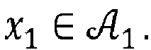


 as its argument and returns the i-th bit c 0(i), i.e.,


 with bit c 0(i) = b.
- The definition of an a posteriori channel L-value of the first layer reads

- By applying the law of total probability, i.e., by suitably averaging over all cell combinations, this can be transformed into

- Iterative demapping becomes feasible by substituting the a priori probabilities, P(x 0) and P(x 1), with extrinsic information obtained from FEC-decoding of the first and second layer. Exploiting additionally the fact that


- It should be clear that on the first demapping pass, the a priori probabilities are unknown and thus they are assumed to be equally distributed with P(x 0) = P(x1 ) = 1/2. Furthermore, from the definition of an L-Value, La = logP(b = 0)/P(b = 1), the connection of the extrinsic soft-information to the bits b can be made, i.e., P(b = 0) = 1/(1 + exp (-La )) and


- Similarly, the a priori information for a cell x1 of the second layer reads

- With (4b) and (4c) inserted into (3), the a posteriori channel L-value for the first layer reads

- And similarly, with (4b) and (4c) inserted into (3), the a posteriori channel L-value for the second layer reads

- The conditional probability of the received cell y is Gaussian with noise
power 

- Eq. (5a) and (5b) can be efficiently computed by repeatedly using the max-star operation, i.e., max *(a, b) = log(ea + eb ) = max(a, b) + log (1 + e -|a-b|). On close inspection, (5a) and (5b) exploit a priori information about the bits themselves, that is La,0 (m) and La,1 (m) for m = i. An elementary principle of any iterative detection scheme is the propagation of truly extrinsic information between component decoders to avoid feeding back statistically dependent information (cf. the article "The Turbo Principle: Tutorial Introduction and State of the Art" by J. Hagenauer, Proc. International Symposium on Turbo Codes and Related Topics, 1997). Hence, the a priori information needs to be subtracted from the demapping output, i.e., the a posteriori channel information, before passing it on to the next decoding stage.
-
Figure 5 is a block diagram which illustrates the process for computing extrinsic channel information for the first layer. Thedemapper 110 accepts three input signals, one of which is the received signal, and two of which are the a priori information generated by the corresponding FEC-decoders, and computes Lch,0 (i) for 0 ≤ i < log2(S 0) according to Equation (5a).Subtractor 120 subtracts the a priori information La,0 from the demapping output. - Not shown in the Figures is the receiver which may comprises a conventional OFDM demodulator followed by a frequency deinterleaver and a time deinterleaver for receiving the compound signal. Both the OFDM demodulator and the frequency deinterleaver and the time deinterleaver are generally known in the art.
-
Figure 6 is a block diagram which illustrates the process for computing extrinsic channel information for the second layer. Thedemapper 210 accepts three input signals, one of which is the received signal, and two of which are the a priori information generated by the corresponding FEC-decoders, and computes Lch,1 (i) for 0 ≤ i < log2 (S 1) according to Equation (5b).Subtractor 220 subtracts the a priori information La,1 from the demapping output. - The demapping operation performed by
demappers - As an intermediate step onwards to a full iterative demapper, the FEC-decoding stages together with the appropriate bit deinterleavers and bit interleavers are added to the demappers of the first and second layer. Together they form the partial demodulators of the first and the second layer as shown in
Figures 7 and 8 , respectively. - As shown in
Figure 7 , the extrinsic channel L-values Lch,0,e are passed through the bit-deinterleaver 130, yielding deinterleaved soft-information L̃ ch,0,e about the first layer's codebits, which are then passed to the FEC-decoder 140, which performs a version of belief-propagation decoding, e.g. the sum-product-algorithm (SPA) in case of LDPC FEC-coding. Belief-propagation decoding is generally known in the art and details of specific algorithms are not relevant for the present invention. - Belief-propagation decoding produces a posteriori FEC L-values L̃ F,0 , based on which extrinsic FEC L-values L̃ F,0,e are obtained by subtracting the extrinsic channel L-values L̃ ch,0,e by means of
subtractor 150. The result is then passed through the bit-interleaver 160 to serve as a priori information La,0 for thedemapper 110 but also, crucially, for the demodulation of the second layer. - Based on the upper layer decoder and the lower layer decoder the partial
iterative demodulator 200 of the second layer follows the same schema, which is shown inFigure 8 . In order to avoid redundancy, a detailed explanation of the elements ofFigure 8 is omitted. -
Figure 9 is a block diagram of a complete iterative demapper according to an embodiment of the present invention for demapping a superposition modulated signal y, which comprises a first layer and a second layer. A generalization to superposition modulated signals with more than two layers is straightforward. - The block diagram of
Figure 9 is a combination of the partial iterative demodulators of the first and the second layer shown inFigures 7 and 8 , respectively, wherein like elements are denoted by like reference numerals. A repetition of the detailed explanation of these elements is omitted. - Arrows in
Figure 9 indicate the flow of information during operation. A corresponding method for iteratively demapping the input signal is summarized in the following listing: - 0) Parameter settings
- a. Choose a maximum number of outer iterations imax ≥0. (This is the number of iterations between second and first layer demodulator.)
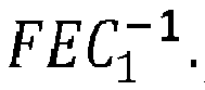
- b. Choose a maximum number of inner iterations imax,FEC0 ≥0 and imax,FEC1 ≥0. (This is the maximum number of FEC-decoder iterations employed in

- c. Set outer iteration counter i to zero.
- d. Initialize the a priori information by setting La,0 and La,1 to zero.
- 1) Demodulate the first layer
- a. Demap the first layer according to Eq. (5a). This yields the a posteriori channel L-value of the first layer, Lch,0 .
- b. Compute the extrinsic information for the upper layer, L ch,0,e = L ch,0 - La,0.
- c. Perform the bit-deinterleaving of Lch,0,e , yielding L̃ ch,0 ,e,
- d. Perform FEC-decoding of L̃ ch,0 ,e, yielding L̃ F,0
- e. Compute the extrinsic FEC information L̃ F,0,e = L̃ F,0 - L̃ ch,0,e .
- f. Perform the bit-deinterleaving of L̃ F,0,e , yielding L a,0 .
- 2) Demodulate the second layer
- a. Demap the second layer according to Eq. (5b). This yields Lch,1 .
- b. Compute the extrinsic information for the lower layer, Lch,1,e = Lch,1 - L a,1 .
- c. Perform the bit-deinterleaving of Lch,1,e, yielding L̃ ch,1,e
- d. Perform FEC-decoding of L̃ ch,1 ,e, yielding L̃ F,1
- e. Compute the extrinsic FEC information L̃ F,1,e = L̃ F,1 - L̃ ch,1 ,e.
- f. Perform the bit-deinterleaving of L̃ F,1 ,e, yielding La,1 .
- 3) Check if an outer code (can be BCH or CRC) of the desired layer confirms that there are no errors. If so, terminate the demodulation. Otherwise go to the next step 4.
- 4) Increase i by 1. If i≤imax, go to
step 1. If i>imax, terminate the demodulation. - The general concept of iterative decoding is known since the first days of turbo coding as invented by Berrou et al. In the configuration of the
Figure 9 , however, it should be appreciated that to generate extrinsic information from the demapper output only one of the a priori L-values is being subtracted, i.e., La,0 from L ch,0 (rather than La,1 ) and La,1 from Lch,1 (rather than La,o ). For clarity, these positions are marked by P0 and P1 inFigure 9 . At first glance, this approach constitutes a deviation from the principle to pass on only extrinsic information as set forth in the above cited article by J. Hagenauer. By careful inspection of the positions, marked by P2 and P3, one can observe that La,1 fed into

- Hard decision SIC as described in the article by S. I. Park et al., is the standard approach for detecting SM-based transmission schemes like LDM and WiB. But Hard decision implies information loss. FEC-decoders naturally provide soft information and reliability information at their output, that is, the magnitude of the L-values of FEC-decoded codebits hint at their reliability. The iterative demapper shown in
Figure 9 makes use of this soft-information by exchanging extrinsic soft-information between partial demodulators. - Although it is suggested by the above listing that demodulation steps for the first layer and the second layer are performed sequentially, both steps may also be performed in parallel. Both options may have specific advantages in terms of hardware requirements and efficiency. However, the difference in these two options is not so much related to implementation details but on how information, in particular updated values of the a priori information, are exchanged between processing of the first layer and the second layer. This difference is illustrated in
Figs. 10A and 10B , which show the flow of information for sequential and parallel processing, respectively. - In a situation where demodulation steps for the first layer and the second layer are performed sequentially, the first iteration of demodulating the first layer is based on the initialization values for the a priori information, i.e., on La,0 = La,1 = 0. The first iteration of demodulating the second layer, however, is already based on the new a prior value La,0 computed by the demodulation step for the first layer. Therefore, sequential operation may be beneficial in a situation where signal strength of the first layer is dominating over the second layer, as it may be the case in LDM.
- On the other hand, when demodulation steps for the first layer and the second layer are performed in parallel, the first iteration for the first layer and the first iteration of the second layer are both based on the initialization values for the a priori information, i.e., on La,0 = La,1 = 0. Subsequent iterations for both layers are then based on results of the immediately preceding steps. Hence, parallel operation treats both layers equal and may be beneficial in a situation where both signal strengths are on a par, as it might be the case in WiB.
- Summarizing, the present invention provides a method and apparatus for demapping superposition modulated signals with improved efficiency. This is achieved by providing a separate iterative demapper for each layer of a superposition modulated signal, and to configure each demapper to exchange soft-information with the other demappers such that each layer is demapped on the basis of soft-information relating to all layers. In this manner, no hard decisions on the FEC decoder output have to be taken and no information is lost.
Claims (9)
- A method for iteratively demapping a received signal (y), said received signal comprising a superposition of at least a first BICM-encoded signal (x0 ) and a second BICM-encoded signal (x1 ), said method comprising the steps of:initializing a priori L-values (La,0 ) for the first signal (x0 ) and a priori L-values (La,1 ) for the second signal;computing, from the received signal (y), a posteriori L-values (Lh,0 ) for the first signal (x0 );updating a priori L-values (La,0 ) for the first signal on the basis of the computed a posteriori L-values (Lch,0 ) for the first signal (x0 );iterating, for the first signal (x0 ), the steps of computing the a posteriori L-values (Lch,0 ) and updating the a priori L-values (La,0 );computing, from the received signal (y), a posteriori L-values (Lch,1 ) for the second signal (x1 );updating a priori L-values (La,1 ) for the second signal (x1 ) on the basis of the computed a posteriori L-values (Lch,1 ) for the second signal (x1 );iterating, for the second signal (x1 ), the steps of computing the a posteriori L-values (Lch,1 ) and updating the a priori L-values (La,1 );characterized in that
the a posteriori L-values (Lh,0 ) for the first signal (x0 ) are computed on the basis of the a priori L-values (La,0 ) for the first signal (x0 ) and the a priori L-values (La,1 ) for the second signal (x1 ); and
the a posteriori L-values (Lch,1 ) for the second signal (x1 ) are computed on the basis of the a priori L-values (La,0 ) for the first signal (x0 ) and the a priori L-values (La,1 ) for the second signal (x1 ). - The method of claim 1, wherein the a posteriori L-values (Lch,0 ) for the first signal (x0 ) and the a posteriori L-values (Lch,1 ) for the second signal (x1 ) are computed according to

 and
and denote the constellation alphabet for the first and the second signal, respectively,
 and
and denote the size of the respective constellation alphabet, ck (i) ∈ {0,1} is the value of the i-th bit mapped to cell xk ∈
 and
and denotes the set of all cells from the alphabet
 with bit ck (i) = b, and p(y|x 0 ,x 1) is the conditional probability of receiving y given x 0 and x 1.
- The method of claim 1 or 2, further comprising the steps of
computing extrinsic L-values (Lch,0,e ) for the first signal (x0 ) by subtracting the a priori L-values (La,0 ) for the first signal (x0 ) from the a posteriori L-values (Lch,0 ) for the first signal (x0 ), wherein the a priori L-values (La,0 ) for the first signal (x0 ) are updated on the basis of the extrinsic L-values (Lch,0,e ) for the first signal (x0 ); and
computing extrinsic L-values (Lch,1,e ) for the second signal (x1 ) by subtracting the a priori L-values (La,1 ) for the second signal (x1 ) from the a posteriori L-values (Lch,1 ) for the second signal (x1 ), wherein the a priori L-values (La,1 ) for the second signal (x1 ) are updated on the basis of the extrinsic L-values (Lch,1,e ) for the second signal (x1 ). - The method of claim 3, wherein updating the a priori L-value (La,0, La,1 ) for at least one of the first and the second signal (x0, x1 ) comprises:deinterleaving the extrinsic L-values (Lch,0,e, Lch,1,e ) for the at least one signal (x0, x1 );performing FEC decoding on the deinterleaved extrinsic L-values for the at least one signal (x0, x1 );subtracting the deinterleaved extrinsic L-values for the at least one signal (x0, x1 ) from the result of the FEC decoding process; andinterleaving a result of the subtraction.
- The method of any of claims 1 to 4, wherein the iterating steps are performed such that a first iteration for computing the a posteriori L-values (Lch,0 ) for the first signal (x0 ) is based on the initialized a priori L-values (La,0, La,1 ) for the first and the second signal (x0, x1 ) and that a first iteration for computing the a posteriori L-values (Lch,1 ) for the second signal (x1 ) is based on the updated a priori L-values (La,0 ) for the first signal and on the initialized a priori L-values (La,1 ) for the second signal (x1 ).
- The method of any of claims 1 to 4, wherein the iterating steps are performed such that both a first iteration for computing the a posteriori L-values (Lch,0 ) for the first signal (x0 ) and a first iteration for computing the a posteriori L-values (Lch,1 ) for the second signal (x1 ) are based on the initialized a priori L-values (La,0, La,1 ) for the first and the second signal (x0, x1 ).
- The method of any of claims 1 to 6, wherein the received signal (y) is a layered-division multiplexing signal with the first signal (x0 ) representing a first layer and the second signal (x1 ) representing a second layer.
- The method of any of claims 1 to 6, wherein the first signal (x0 ) is a first wideband transmission signal transmitted by a first transmitter and the second signal (x1 ) is a second wideband transmission signal transmitted by a second transmitter in the same frequency band as the first wideband transmission signal.
- An apparatus for iteratively demapping a received signal (y), said received signal comprising a superposition of at least a first BICM-encoded signal (x0 ) and a second BICM-encoded signal (x1 ), said apparatus comprising:a first demapper for demapping the first signal from the received signal by iteratively computing a posteriori L-values (Lch,0 ) of the first signal and updating a priori L-values (La,0 ) of the first signal on the basis of the computed a posteriori L-values (Lch,0 ) of the first signal; anda second demapper for demapping the second signal from the received signal by iteratively computing a posteriori L-values (Lch,1 ) of the second signal and updating a priori L-values (La,1 ) of the second signal on the basis of the computed a posteriori L-values (Lch,1 ) of the second signal,characterized in that
the first demapper is configured for computing the a posteriori L-values (Lh,0 ) of the first signal on the basis of the a priori L-values (La,0 ) of the first signal and the a priori L-values (La,1 ) of the second signal; and
the second demapper is configured for computing the a posteriori L-values (Lch,1 ) of the second signal on the basis of the a priori L-values (La,0 ) of the first signal and the a priori L-values (La,1 ) of the second signal.
Priority Applications (1)
| Application Number | Priority Date | Filing Date | Title |
|---|---|---|---|
| EP16203534.9A EP3334075A1 (en) | 2016-12-12 | 2016-12-12 | Iterative demapping for superposition modulation |
Applications Claiming Priority (1)
| Application Number | Priority Date | Filing Date | Title |
|---|---|---|---|
| EP16203534.9A EP3334075A1 (en) | 2016-12-12 | 2016-12-12 | Iterative demapping for superposition modulation |
Publications (1)
| Publication Number | Publication Date |
|---|---|
| EP3334075A1 true EP3334075A1 (en) | 2018-06-13 |
Family
ID=57629253
Family Applications (1)
| Application Number | Title | Priority Date | Filing Date |
|---|---|---|---|
| EP16203534.9A Withdrawn EP3334075A1 (en) | 2016-12-12 | 2016-12-12 | Iterative demapping for superposition modulation |
Country Status (1)
| Country | Link |
|---|---|
| EP (1) | EP3334075A1 (en) |
Cited By (2)
| Publication number | Priority date | Publication date | Assignee | Title |
|---|---|---|---|---|
| US10897388B2 (en) | 2017-12-08 | 2021-01-19 | Panasonic Intellectual Property Corporation Of America | Transmitter, receiver, transmission method, and reception method |
| US11637567B2 (en) * | 2018-07-30 | 2023-04-25 | Sony Semiconductor Solutions Corporation | Decoding circuit |
Citations (3)
| Publication number | Priority date | Publication date | Assignee | Title |
|---|---|---|---|---|
| EP2255473A1 (en) * | 2008-03-03 | 2010-12-01 | NTT DoCoMo, Inc. | A layered receiver structure |
| US20130022088A1 (en) * | 2009-12-02 | 2013-01-24 | France Telecom | Method for transmitting a digital signal for a semi-orthogonal marc system having half-duplex relay, and corresponding program product and relay device |
| US20130034044A1 (en) * | 2009-09-17 | 2013-02-07 | France Telecom | Method of transmitting a digital signal for a marc system with a full-duplex relay, a corresponding program product and relay device |
-
2016
- 2016-12-12 EP EP16203534.9A patent/EP3334075A1/en not_active Withdrawn
Patent Citations (3)
| Publication number | Priority date | Publication date | Assignee | Title |
|---|---|---|---|---|
| EP2255473A1 (en) * | 2008-03-03 | 2010-12-01 | NTT DoCoMo, Inc. | A layered receiver structure |
| US20130034044A1 (en) * | 2009-09-17 | 2013-02-07 | France Telecom | Method of transmitting a digital signal for a marc system with a full-duplex relay, a corresponding program product and relay device |
| US20130022088A1 (en) * | 2009-12-02 | 2013-01-24 | France Telecom | Method for transmitting a digital signal for a semi-orthogonal marc system having half-duplex relay, and corresponding program product and relay device |
Non-Patent Citations (5)
| Title |
|---|
| E. STARE; J. J. GIMENEZ; P. KLENNER: "WiB: a new system concept for digital terrestrial television (DTT", IBC CONFERENCE, 2016 |
| J. HAGENAUER: "The Turbo Principle: Tutorial Introduction and State of the Art", PROC. INTERNATIONAL SYMPOSIUM ON TURBO CODES AND RELATED TOPICS, 1997 |
| P. P. BERGMANS; T. M. COVER: "Cooperative broadcasting", IEEE TRANS. INF. THEORY, vol. 20, no. 3, May 1974 (1974-05-01), pages 317 - 324 |
| S. I. PARK: "Low Complexity Layered Division for ATSC 3.0", IEEE TRANSACTIONS ON BROADCASTING, vol. 62, no. 1, March 2016 (2016-03-01), pages 233 - 243, XP011608942, DOI: doi:10.1109/TBC.2015.2492459 |
| XIAODONG WANG ET AL: "Iterative (Turbo) Soft Interference Cancellation and Decoding for Coded CDMA", IEEE TRANSACTIONS ON COMMUNICATIONS, IEEE SERVICE CENTER, PISCATAWAY, NJ. USA, vol. 47, no. 7, 1 July 1999 (1999-07-01), XP011009462, ISSN: 0090-6778 * |
Cited By (4)
| Publication number | Priority date | Publication date | Assignee | Title |
|---|---|---|---|---|
| US10897388B2 (en) | 2017-12-08 | 2021-01-19 | Panasonic Intellectual Property Corporation Of America | Transmitter, receiver, transmission method, and reception method |
| US11431545B2 (en) | 2017-12-08 | 2022-08-30 | Panasonic Intellectual Property Corporation Of America | Transmitter, receiver, transmission method, and reception method |
| US11637736B2 (en) | 2017-12-08 | 2023-04-25 | Panasonic Intellectual Property Corporation Of America | Transmitter, receiver, transmission method, and reception method |
| US11637567B2 (en) * | 2018-07-30 | 2023-04-25 | Sony Semiconductor Solutions Corporation | Decoding circuit |
Similar Documents
| Publication | Publication Date | Title |
|---|---|---|
| US10574390B2 (en) | Systems and methods for advanced iterative decoding and channel estimation of concatenated coding systems | |
| US9252813B2 (en) | Iterative decoding of LDPC codes with iteration scheduling | |
| Perez-Calderon et al. | Simplified rotated constellation demapper for second generation terrestrial digital video broadcasting | |
| EP3813278B1 (en) | Multilevel polar-coded modulation transmitting and receiving methods and devices | |
| Fan et al. | Low-complexity rotated QAM demapper for the iterative receiver targeting DVB-T2 standard | |
| Li et al. | Efficient iterative receiver for bit-Interleaved Coded Modulation according to the DVB-T2 standard | |
| Hong et al. | Simplified two-dimensional non-uniform constellation demapping algorithm for ATSC3. 0 | |
| Honfoga et al. | Comparison of low complexity demapper algorithms applied to rotated constellation in DVB-T2 | |
| HONFOGA et al. | Low complexity demapping algorithms survey in DVB-T2: Rotated constellation case study | |
| EP3481019B1 (en) | Efficient decoding of superposition modulation | |
| CN102006086B (en) | Soft-input and soft-output decoding device for (n,k) square codes | |
| WO2006129666A1 (en) | Digital signal transmitting system, receiving apparatus and receiving method | |
| Živić et al. | Iterative algorithm for OFDM transmission over Rayleigh channels | |
| CN121841914A (en) | Communication method and related device of power domain non-orthogonal multiple access system based on symmetrical hamming distance constellation | |
| Chen et al. | Simplified universal soft demapper for gray-mapped constellation | |
| Ahmed et al. | Complexity reduced SBI estimation in iterative MIMO systems | |
| KR20150015091A (en) | Method for transmission and reception using asymmetric modulation constellation |
Legal Events
| Date | Code | Title | Description |
|---|---|---|---|
| PUAI | Public reference made under article 153(3) epc to a published international application that has entered the european phase |
Free format text: ORIGINAL CODE: 0009012 |
|
| AK | Designated contracting states |
Kind code of ref document: A1 Designated state(s): AL AT BE BG CH CY CZ DE DK EE ES FI FR GB GR HR HU IE IS IT LI LT LU LV MC MK MT NL NO PL PT RO RS SE SI SK SM TR |
|
| AX | Request for extension of the european patent |
Extension state: BA ME |
|
| STAA | Information on the status of an ep patent application or granted ep patent |
Free format text: STATUS: THE APPLICATION IS DEEMED TO BE WITHDRAWN |
|
| 18D | Application deemed to be withdrawn |
Effective date: 20181214 |