EP3333991A1 - Method for manufacturing spark plug - Google Patents
Method for manufacturing spark plug Download PDFInfo
- Publication number
- EP3333991A1 EP3333991A1 EP17204775.5A EP17204775A EP3333991A1 EP 3333991 A1 EP3333991 A1 EP 3333991A1 EP 17204775 A EP17204775 A EP 17204775A EP 3333991 A1 EP3333991 A1 EP 3333991A1
- Authority
- EP
- European Patent Office
- Prior art keywords
- electrode
- ground electrode
- tip
- pressing part
- pressing
- Prior art date
- Legal status (The legal status is an assumption and is not a legal conclusion. Google has not performed a legal analysis and makes no representation as to the accuracy of the status listed.)
- Granted
Links
- 238000000034 method Methods 0.000 title claims abstract description 19
- 238000004519 manufacturing process Methods 0.000 title claims abstract description 14
- 238000003825 pressing Methods 0.000 claims abstract description 107
- 238000003466 welding Methods 0.000 claims abstract description 46
- 229910052751 metal Inorganic materials 0.000 claims description 34
- 239000002184 metal Substances 0.000 claims description 34
- 239000012212 insulator Substances 0.000 claims description 25
- PXHVJJICTQNCMI-UHFFFAOYSA-N Nickel Chemical compound [Ni] PXHVJJICTQNCMI-UHFFFAOYSA-N 0.000 description 6
- 238000005452 bending Methods 0.000 description 4
- 238000005304 joining Methods 0.000 description 4
- 229910045601 alloy Inorganic materials 0.000 description 3
- 239000000956 alloy Substances 0.000 description 3
- 239000007769 metal material Substances 0.000 description 3
- 229910052759 nickel Inorganic materials 0.000 description 3
- RYGMFSIKBFXOCR-UHFFFAOYSA-N Copper Chemical compound [Cu] RYGMFSIKBFXOCR-UHFFFAOYSA-N 0.000 description 2
- 229910001209 Low-carbon steel Inorganic materials 0.000 description 2
- 229910052802 copper Inorganic materials 0.000 description 2
- 239000010949 copper Substances 0.000 description 2
- 230000005489 elastic deformation Effects 0.000 description 2
- 230000002452 interceptive effect Effects 0.000 description 2
- 229910000510 noble metal Inorganic materials 0.000 description 2
- PNEYBMLMFCGWSK-UHFFFAOYSA-N aluminium oxide Inorganic materials [O-2].[O-2].[O-2].[Al+3].[Al+3] PNEYBMLMFCGWSK-UHFFFAOYSA-N 0.000 description 1
- 239000011247 coating layer Substances 0.000 description 1
- 230000006835 compression Effects 0.000 description 1
- 238000007906 compression Methods 0.000 description 1
- 238000007796 conventional method Methods 0.000 description 1
- 238000002788 crimping Methods 0.000 description 1
- 230000006866 deterioration Effects 0.000 description 1
- 238000012986 modification Methods 0.000 description 1
- 230000004048 modification Effects 0.000 description 1
Images


Classifications
-
- H—ELECTRICITY
- H01—ELECTRIC ELEMENTS
- H01T—SPARK GAPS; OVERVOLTAGE ARRESTERS USING SPARK GAPS; SPARKING PLUGS; CORONA DEVICES; GENERATING IONS TO BE INTRODUCED INTO NON-ENCLOSED GASES
- H01T13/00—Sparking plugs
- H01T13/20—Sparking plugs characterised by features of the electrodes or insulation
- H01T13/39—Selection of materials for electrodes
-
- B—PERFORMING OPERATIONS; TRANSPORTING
- B23—MACHINE TOOLS; METAL-WORKING NOT OTHERWISE PROVIDED FOR
- B23K—SOLDERING OR UNSOLDERING; WELDING; CLADDING OR PLATING BY SOLDERING OR WELDING; CUTTING BY APPLYING HEAT LOCALLY, e.g. FLAME CUTTING; WORKING BY LASER BEAM
- B23K11/00—Resistance welding; Severing by resistance heating
- B23K11/30—Features relating to electrodes
- B23K11/3009—Pressure electrodes
-
- H—ELECTRICITY
- H01—ELECTRIC ELEMENTS
- H01T—SPARK GAPS; OVERVOLTAGE ARRESTERS USING SPARK GAPS; SPARKING PLUGS; CORONA DEVICES; GENERATING IONS TO BE INTRODUCED INTO NON-ENCLOSED GASES
- H01T21/00—Apparatus or processes specially adapted for the manufacture or maintenance of spark gaps or sparking plugs
- H01T21/02—Apparatus or processes specially adapted for the manufacture or maintenance of spark gaps or sparking plugs of sparking plugs
-
- B—PERFORMING OPERATIONS; TRANSPORTING
- B23—MACHINE TOOLS; METAL-WORKING NOT OTHERWISE PROVIDED FOR
- B23K—SOLDERING OR UNSOLDERING; WELDING; CLADDING OR PLATING BY SOLDERING OR WELDING; CUTTING BY APPLYING HEAT LOCALLY, e.g. FLAME CUTTING; WORKING BY LASER BEAM
- B23K11/00—Resistance welding; Severing by resistance heating
- B23K11/002—Resistance welding; Severing by resistance heating specially adapted for particular articles or work
-
- B—PERFORMING OPERATIONS; TRANSPORTING
- B23—MACHINE TOOLS; METAL-WORKING NOT OTHERWISE PROVIDED FOR
- B23K—SOLDERING OR UNSOLDERING; WELDING; CLADDING OR PLATING BY SOLDERING OR WELDING; CUTTING BY APPLYING HEAT LOCALLY, e.g. FLAME CUTTING; WORKING BY LASER BEAM
- B23K11/00—Resistance welding; Severing by resistance heating
- B23K11/30—Features relating to electrodes
- B23K11/31—Electrode holders and actuating devices therefor
-
- H—ELECTRICITY
- H01—ELECTRIC ELEMENTS
- H01T—SPARK GAPS; OVERVOLTAGE ARRESTERS USING SPARK GAPS; SPARKING PLUGS; CORONA DEVICES; GENERATING IONS TO BE INTRODUCED INTO NON-ENCLOSED GASES
- H01T13/00—Sparking plugs
- H01T13/20—Sparking plugs characterised by features of the electrodes or insulation
- H01T13/32—Sparking plugs characterised by features of the electrodes or insulation characterised by features of the earthed electrode
-
- B—PERFORMING OPERATIONS; TRANSPORTING
- B23—MACHINE TOOLS; METAL-WORKING NOT OTHERWISE PROVIDED FOR
- B23K—SOLDERING OR UNSOLDERING; WELDING; CLADDING OR PLATING BY SOLDERING OR WELDING; CUTTING BY APPLYING HEAT LOCALLY, e.g. FLAME CUTTING; WORKING BY LASER BEAM
- B23K2101/00—Articles made by soldering, welding or cutting
- B23K2101/36—Electric or electronic devices
Definitions
- the present invention relates to a method for manufacturing a spark plug, particularly of the type in which a tip is joined by resistance welding to a ground electrode.
- a spark plug is conventionally known, in which a tip is joined to a ground electrode.
- Japanese Laid-Open Patent Publication No. 2006-185784 discloses a technique of manufacturing this type of spark plug by laser welding the tip to the ground electrode after positioning the ground electrode.
- a method for manufacturing a spark plug comprising: an insulator holding therein a center electrode; a metal shell surrounding a part of the insulator; a ground electrode joined to the metal shell, the ground electrode having an inner surface facing the center electrode and an outer surface located opposite the inner surface; and a tip welded to a tip weld site on the inner surface of the ground electrode, the method comprising:
- This method is characterized in that, in a state where the ground electrode is positioned with respect to the first electrode by means of the pressing member, the tip is pressed against the ground electrode by means of the second electrode and then resistance welded to the ground electrode by the passage of electric current between the first and second electrodes. It is therefore possible to improve the positioning accuracy of the tip with respect to the ground electrode.
- a method for manufacturing a spark plug as described above wherein, in the positioning step, the pressing member presses the ground electrode in the same direction as a direction in which the second electrode presses the tip in the tip pressing step.
- a method for manufacturing a spark plug as described above wherein a surface of the first electrode for contact with the outer surface of the ground electrode is larger in area than the outer surface of the ground electrode.
- a method for manufacturing a spark plug as described above wherein the method further comprises, before the welding step, a supporting step of supporting the insulator by applying a force to the insulator in the same direction as a force exerted on the ground electrode by the first electrode.
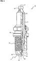
- FIG. 1 is a schematic view, partially in section, of a spark plug 10 according to one exemplary embodiment of the present invention.
- the bottom and top sides of FIG. 1 are referred to as front and rear sides of the spark plug 10, respectively.
- the spark plug 10 includes an insulator 11, a metal shell 16 and a ground electrode 18.
- the insulator 11 is made of e.g. alumina, which has excellent mechanical properties and high-temperature insulating properties, in a cylindrical shape with an axial hole 12 formed therethrough along an axis O.
- a center electrode 13 is formed in a rod shape so as to extend along the axis O.
- the center electrode 13 has a core made of copper or a copper-based alloy and a coating layer made of nickel or a nickel-based alloy.
- the center electrode 13 is held in a front end side of the axial hole 12 with a front end of the center electrode 13 being exposed from the axial hole 12.
- a noble metal-containing tip 14 is joined to the front end of the center electrode 13.
- a metal terminal 15 is made of a conductive metal material (such as low carbon steel) in a rod shape and press-fitted in a rear end side of the axial hole 12 with a rear end portion of the metal terminal 15 being exposed from the axial hole 12 for connection with a high-voltage cable (not shown).
- a conductive metal material such as low carbon steel
- the metal shell 16 is made of a conductive metal material (such as low carbon steel) in a substantially cylindrical shape.
- the metal shell 16 is fixed by crimping onto a front end part of the outer circumference of the insulator 11 such that the insulator 11 is held in the metal shell 16 and such that the rear end portion of the metal terminal 15 is kept apart from the metal shell 16 in the direction of the axis O.
- a thread portion 17 is formed on an outer circumferential surface of the metal shell 16 so as to be screwed into a screw hole of an engine (not shown).
- the ground electrode 18 is made of a metal material (such as nickel-based alloy) and joined at a base end face thereof by welding to a front end of the metal shell 16.
- the ground electrode 18 is rectangular in cross section and bent at a middle portion thereof such that a distal end portion of the ground electrode 18 is opposed to the front end of the center electrode 13 (tip 14). More specifically, the ground electrode 18 has: an inner surface 19 facing the center electrode 13; an outer surface (back surface) 20 located opposite the inner surface 19; first and second side surfaces 21 and 22 (also see FIG. 2A ) connecting the inner surface 19 to the outer surface 20; and a distal end face 23 located opposite the base end face.
- a noble metal-containing tip 24 is joined by welding to a region of the inner surface 19 of the ground electrode 18 located adjacent to the distal end face 23.
- the region of the inner surface 19 to which the tip 24 is welded is hereinafter referred to as a "tip weld site 26 (see e.g. FIGS. 2A and 2B )".
- spark gap between the tip 24 on the ground electrode 18 and the tip 14 on the center electrode 13.
- the above-structured spark plug 10 can be manufactured by the following procedure. After the tip 14 is joined to the front end of the center electrode 13, the center electrode 13 is inserted in the axial hole 12 of the insulator 11 such that the front end of the center electrode 13 (tip 14) is exposed outside from the axial hole 12. The metal terminal 15 is then inserted in the axial hole 12 of the insulator 11 and electrically connected to the center electrode 3. After the ground electrode 18 (in a straight unbent form) is joined at the base end face thereof to the metal shell 16, the metal shell 16 is fixed to the outer circumference of the insulator 11. Thus provided is a plug work 25 in which the insulator 11, the center electrode 13 with the tip 14, the metal terminal 15, the metal shell 16 and the ground electrode 18 are assembled together. The tip 24 is joined to the inner surface 19 of the ground electrode 18 of the plug work 25. Finally, the ground electrode 18 is bent such that the tip 24 is opposed to the center electrode 13 (tip 14).
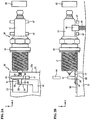
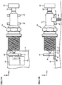
- FIGS. 2A and 2B are an elevation view and a side view of a welding device 30 used for joining of the tip 24 to the ground electrode 18.
- the welding device 30 is configured to hold the ground electrode 18 of the plug work 25 in position and join the tip 24 to the ground electrode 18 by resistance welding (also see FIG. 1 ).
- resistance welding also see FIG. 1 .
- mutually perpendicular X, Y and Z directions of the welding device 30 are represented by arrows X, Y and Z in FIGS. 2A and 2B .
- the welding device 30 includes a first electrode 31 formed with a flat surface 32, a reference member 33 formed with first and second surfaces 34 and 35, first to fourth pressing parts 41 to 44 as a pressing member, a support member 45 and a second electrode 36 (see FIG. 7 ).
- the plug work 25 to which the tip 24 is to be welded by the welding device 30 is obtained by joining the ground electrode 18 to the metal shell 16 and fixing the insulator 11 in the metal shell 16.
- the ground electrode 18 is in a state of extending in a straight form before bending.
- the first and second electrodes 31 and 36 are used to weld the tip 24 to the tip weld site 26 of the ground electrode 18 by the passage of electric current.
- the flat surface 32 of the first electrode 31 serves as a reference plane for positioning of the ground electrode 18 in the Z direction.
- the flat surface 32 of the first electrode 31 is made larger in area than the outer surface 20 of the ground electrode 18.
- the reference member 33 is fixed in position to the flat surface 32 of the first electrode 31 and used to restrict the position of the ground electrode 18 on the flat surface 32 of the first electrode 31. Since the length and width of the ground electrode 18 can be varied depending on the type of the spark plug 10, the welding device 30 includes a mechanism (not shown) for adjusting the position of the reference member 33 on the flat surface 32 according to the length and width of the ground electrode 18 and fixing the reference member 33 to the flat surface 32.
- the first surface 34 of the reference member 33 intersects the flat surface 32 of the first electrode 31 and serves as a reference plane for positioning of the ground electrode 18 on the flat surface 32 in the Y direction.
- the second surface 35 of the reference member 33 perpendicularly intersects the flat surface 32 and the first surface 34 via corners and serves as a reference plane for positioning of the ground electrode 18 on the flat surface 32 in the X direction.
- the plug work 25 is placed in the welding device 30 such that the axis O of the plug work 25 is aligned in the X direction of the welding device 30.
- the position of an edge 32a of the flat surface 32 of the first electrode 31 is adjusted so as to, when the ground electrode 18 of the plug work 25 is arranged on the first electrode 31 along the first and second surfaces 34 and 35 of the reference member 33, allow substantially the entire outer surface 20 of the ground electrode 18 to make contact with the flat surface 32 while keeping the metal shell 16 of the plug work 25 free from contact with the flat surface 32. This ensures contact of substantially the entire outer surface 20 of the ground electrode 18 with the flat surface 32 of the first electrode 31 irrespective of the thread portion 17 on the outer circumferential surface of the metal shell 16.
- the first to fourth pressing parts 41 to 44 are used as the pressing member to press the plug work 25 onto the first electrode 31 and the reference member 33 and hold the ground electrode 18 of the plug work 25 in position with respect to the first electrode 31.
- Each of the first to fourth pressing parts 41 to 44 is intermittently driven in a reciprocating manner by an actuator such as pneumatic cylinder (not shown).
- the first pressing part 41 is disposed at a position opposed to the flat surface 32 of the first electrode 31 and is driven by the actuator in the Z direction to be moved closer to or away from the flat surface 32. As seen in FIG. 2A , the first pressing part 41 is located between the edge 32a of the flat surface 32 and the reference member 33 in the X direction and, even when moved closer to the flat surface 32, does not interfere with the reference member 33.
- the second pressing part 42 is slidably disposed on the flat surface 32 of the first electrode 31, at a position opposed to the first surface 34 of the reference member 33, and is driven by the actuator in the Y direction to be moved closer to or away from the first surface 34. As seen in FIG. 2B (Y-direction side view), the second pressing part 42 is located farther apart from the edge 32a than the first pressing part 41. Further, the second pressing part 42 does not interfere with the second surface 35 of the reference member 33 and the first pressing part 41 even when moved closer to the first surface 34 as seen in FIG. 2A .
- the third pressing part 43 is disposed in substantially the same plane as an imaginary plane extending in the X direction from the flat surface 32 of the first electrode 31, at a position apart from the first electrode 31 and opposed to the second surface 35 of the reference member 33, and is driven by the actuator in the X direction to be moved closer to or away from the second surface 35.
- a thickness of each of the second pressing part 42 and the reference member 33 is made smaller than a thickness of the ground electrode 18 (i.e. a distance between the inner surface 19 and the outer surface 20). This prevents interference of the second electrode 36 (by which the tip 24 is pressed against the ground electrode 18) with the second pressing part 42 and the reference member 33 during the after-mentioned tip pressing and welding steps (see FIG. 7 ).
- the fourth pressing part 44 is disposed at a position opposed to the flat surface 32 of the first electrode 31, while overlapping a portion of the first pressing part 41 in the Z direction, and is driven by the actuator in the Z direction to be moved closer to or away from the flat surface 32.
- the fourth pressing part 44 when moved closer to flat surface 32, interferes with the first pressing part 41.
- the support member 45 is arranged at a position apart from the first electrode 31 in the X direction and between the first electrode 31 and the third pressing part 43.
- the support member 45 is elastically supported by a spring 46.
- a compression coil spring is provided as the spring 46 to apply an elastic force to the support member 45 in the Z direction.
- a pair of restriction members 47 are arranged to hold the support member 45 therebetween and restrict elastic vibration of the support member 45 caused by the spring 46. More specifically, the restriction members 47 are disposed on both sides of the support member 45 at positions apart from the support member 45 in the X direction perpendicular to the direction of vibration of the support member 45 (Z direction). The restriction members 47 are driven by an actuator as pneumatic cylinder (not shown) and moved closer to or away from the support member 45.
- the tip 24 is joined to the ground electrode 18 by the welding device 30 through the following positioning step, supporting step, tip pressing step and welding step.
- FIGS. 3A , 4A , 5A and 6A are elevation views of the welding device 30 during the positioning step; and FIGS. 3B , 4A , 5B and 6A are side views of the welding device 30 during the positioning step.
- FIG. 7 is a side view of the welding device 30 during the tip pressing and welding steps.
- the plug work 25 is placed in the welding device 30 such that the axis O of the plug work 25 is aligned with the X direction of the welding device 30 as shown in FIGS. 2A and 2B .
- the ground electrode 18 of the plug work 25 is situated between the reference member 33 and the second pressing part 42 with the first side surface 21 of the ground electrode 18 being opposed to the first surface 34 of the reference member 33 and with the distal end face 23 of the ground electrode 18 being opposed to the second surface 35 of the reference member 33.
- the first pressing part 41 is driven by the actuator in the direction closer to the flat surface 32 of the first electrode 31 and brought into contact with any region of the inner surface 19 of the ground electrode 18 other than the tip weld site 26 (e.g. a region of the inner surface 19 between the tip weld site 26 and the metal shell 16) so as to press the outer surface 20 of the ground electrode 18 against the flat surface 32 of the first electrode 31.
- the thrust of the actuator for driving the first pressing part 41 is controlled in such a manner that the ground electrode 18 is pressed against the first electrode 31 with a relatively small force by the first pressing part 41. By this, the ground electrode 18 is temporarily fixed to the first electrode 31.
- the insulator 11 of the plug work 25 is supported by the support member 45 under the elastic force of the spring 46.
- the spring 46 applies its elastic force to the support member 45 in the same direction as the direction of the force exerted on the ground electrode 18 by the first electrode 31 being pressed by the first pressing part 41.
- the plug work 25 is supported at both end sides thereof by the first electrode 31, the first pressing part 41 and the support member 45.
- the load of the first pressing part 41 for pressing the ground electrode 18 against the first electrode 13 can be thus reduced as compared with the case where the plug work 25 is supported in a cantilever state by the first electrode 31 and the first pressing part 41.
- the bending load exerted on the ground electrode 18 under the own weight of the plug work 25 can be suppressed to prevent deformation of the ground electrode 18.
- the second pressing part 42 is driven by the actuator in the direction closer to the first surface 34 of the reference electrode 33 and brought into contact with the second side surface 22 of the ground electrode 18 as shown in FIGS. 3A and 3B in the positioning step.
- the thrust of the actuator for driving the second pressing part 42 is controlled in such a manner that the ground electrode 18 is slid over the flat surface 32 toward the first surface 34 against the frictional force caused due to pressing of the ground electrode 18 against the first electrode 31 by the first pressing part 41.
- the ground electrode 18 is accordingly held between the first surface 34 and the second pressing part 42 and positioned in the Y-direction with respect to the first electrode 31.
- the load of the first pressing part 41 for pressing the ground electrode 18 against the first electrode 31 is reduced to decrease the frictional force caused due to pressing of the ground electrode 18 against the first electrode 31 by the first pressing part 41.
- the thrust of the actuator for driving the second pressing part 42 is hence prevented from becoming excessively high.
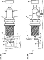
- the third pressing part 43 is driven by the actuator in the direction closer to the second surface 35 of the reference electrode 33 and brought into contact to the metal terminal 15 of the plug work 25 in the positioning step as shown in FIGS. 4A and 4B .
- the thrust of the actuator for driving the third pressing part 43 is controlled in such a manner that the ground electrode 18 is slid over the flat surface 32 toward the second surface 35 against the frictional force caused due to pressing of the ground electrode 18 against the first electrode 31 by the first pressing part 41 and against the frictional force caused due to pressing of the ground electrode 18 against the reference member 33 by the second pressing part 42.
- the plug work 25 is accordingly held between the second surface 35 and the third pressing part 43 so that the ground electrode 18 is positioned in the X direction with respect to the first electrode 31.
- the support member 45 (which is brought into contact with the insulator 11 of the plug work 25) is supported by the spring 46.
- the spring 46 By causing elastic deformation of the spring 46 in the X direction, the support member 45 is prevented by X-direction elastic deformation of the spring 46 from interfering with X-direction movement of the plug work 25 by the third pressing part 43.
- the spring 46 can be elastically deformed to follow the peak-to-valley shape of the corrugation so as to prevent the support member 45 from interfering with X-direction movement of the plug work 25.
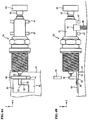
- the fourth pressing part 44 is then driven by the actuator in the direction closer to the flat surface 32 of the first electrode 31 and brought into contact with the first pressing part 41 as shown in FIGS. 5A and 5B in the positioning step.
- the fourth pressing part 44 applies a load to the first pressing part 41 such that the ground electrode 18, which has been pressed against the first electrode 31 by the first pressing part 41, is further pressed against the first electrode 31.
- the ground electrode 18 is fixed under the loads of the first and fourth pressing parts 41 and 44. The positioning of the ground electrode 18 with respect to the first electrode 31 is hereby completed.
- the support member 45 is held between the restriction members 47 so as to restrict elastic vibration of the support member 45 as shown in FIGS. 6A and 6B .
- the plug work 25 is prevented from vibrating in the Z direction such that the Z-direction angle of the plug work 25 relative to the flat surface 32 of the first electrode 31 is not varied.
- the tip 24 is arranged on the tip weld site 26 of the inner surface 19 of the ground electrode 18 as shown in FIGS. 7A and 7B .
- the welding device 30 is set depending on the length, width and thickness of the ground electrode 18 in such a manner that the tip 24 is arranged at a predetermined distance away from the first and second surfaces 34 and 35 of the reference member 33 in the X and Y directions (see FIG. 2A ) and at a predetermined distance away from the flat surface 32 of the first electrode 31 in the Z direction.
- the tip 24 is pressed onto the tip weld site 26 of the ground electrode 18 by the second electrode 36 so that a weld joint surface of the tip 24 is brought into intimate contact with the tip weld site 26 of the ground electrode 18.
- the tip 24 is resistance welded to the ground electrode 18 by the passage of electric current between the first electrode 31 and the second electrode 36.
- the first side surface 21 and the distal end face 23 of the ground electrode 18 are positioned with respect to the first and second surfaces 34 and 35 of the reference member 33 that has been fixed to the flat surface 32 of the first electrode 31.
- the ground electrode 18 is positioned with respect to the first electrode 31.
- the outer surface 20 of the ground electrode 18 is brought into intimate contact with the flat surface 32 of the first electrode 31.
- the tip 24 is arranged on the tip weld site 26 of the positioned ground electrode 18. It is therefore possible to improve the positioning accuracy of the tip 24 with respect to the ground electrode 18.
- variations in the inclination (i.e. contact area) and contact resistance of the tip 24 relative to the tip weld site 26 can be suppressed to prevent variations in the amount of embedment of the tip 24 in the ground electrode 18 by resistance welding and suppress variations in the joint strength of the tip 24 to the ground electrode 18.
- the tip weld site 26 is set into position with respect to the ground electrode 18 (more specifically, the reference member 33 fixed to the flat surface 32 of the first electrode 31 with which the ground electrode 18 has been held in contact in the present embodiment).
- the operation for correcting the inclination of the ground electrode 18 relative to the axis O of the metal shell 16 can be omitted to achieve simplification of manufacturing process. As there does not occur new inclination of the ground electrode 18 by the correcting operation, it is possible to prevent deterioration in the joint strength of the tip 24 to the ground electrode 18.
- the first and fourth pressing parts 41 and 44 press the ground electrode 18 against the first electrode 31 in the positioning step in the same direction as the direction in which the second electrode 36 (see FIG. 7 ) presses the tip 24 against the ground electrode 18 in the tip pressing step.
- This allows better contact between the flat surface 32 of the first electrode 31 and the outer surface 20 of the ground electrode 18. It is thus possible to effectively suppress variations in the contact resistance between the flat surface 32 of the first electrode 31 and the back surface 20 of the ground electrode 18 and then prevent or minimize variations in the joint strength of the tip 24 to the ground electrode 18.
- the outer surface 20 of the ground electrode 18 can be stably pressed against the flat surface 32 of the first electrode 31. It is thus possible to effectively suppress variations in the contact resistance between the first electrode 31 and the ground electrode 18 and prevent or minimize variations in the joint strength of the tip 24 to the ground electrode 18.
- the support member 45 supports the plug work 25 by applying the force to the insulator 11 in the same direction (i.e. Z direction) as the force exerted by the first electrode 31 onto the ground electrode 18. Namely, the plug work 25 is supported at both end sides thereof by the first electrode 31, the first pressing part 41 and the support member 45.
- the bending load exerted on the ground electrode 18 under the own weight of the plug work 25 can be reduced so as to prevent the loads of the first and fourth pressing parts 41 and 44 from being canceled out by the bending load and to easily bring the outer surface 20 of the ground electrode 18 into contact with the flat surface 32 of the first electrode 31. It is thus possible to more effectively suppress variations in the contact resistance between the first electrode 31 and the ground electrode 18 and prevent or minimize variations in the joint strength of the tip 24 to the ground electrode 18.
- the support member 45 supports the insulator 11, which is located farther apart from the edge 32 of the first electrode 31 than the metal shell 16, so that the plug work 25 can be stably held and supported as compared with the case where the support member 45 supports the metal shell 16. This ensures intimate contact between the outer surface 20 of the ground electrode 18 and the flat surface 20 of the first electrode 31. It is thus possible to effectively suppress variations in the contact resistance between the first electrode 31 and the ground electrode 18.
- the second and third pressing parts 42 and 43 are driven so that the ground electrode 18 is over the first electrode 31 by the second and third pressing parts 42 and 43 while being pressed toward the first electrode 31 by the first pressing part 41.
- This allows better contact between the flat surface 32 of the first electrode 31 and the back surface 20 of the ground electrode 18. It is thus possible to effectively suppress variations in the contact resistance between the first electrode 31 and the ground electrode 18.
- the driving order of the pressing parts 41 to 44 in the positioning step is not particularly limited although the first pressing part 41, the second pressing part 42, the third pressing part 43 and the fourth pressing part 44 are driven in this order in the above embodiment.
- the driving order of the pressing parts 41 to 44 can be set as appropriate.
- the restriction members 47 are driven to restrict elastic vibration of the support member 45 after the positioning of the ground electrode 18 by driving the pressing parts 41 to 44.
- the driving timing of the restriction members 47 is however not limited to such timing.
- the restriction members 47 can be driven at any timing after bringing the ground electrode 18 into contact with the first electrode 31 by the first pressing part 41, i.e., after fixing the position of the plug work 25 in the Z direction.
Landscapes
- Engineering & Computer Science (AREA)
- Mechanical Engineering (AREA)
- Manufacturing & Machinery (AREA)
- Spark Plugs (AREA)
Abstract
Description
- The present invention relates to a method for manufacturing a spark plug, particularly of the type in which a tip is joined by resistance welding to a ground electrode.
- A spark plug is conventionally known, in which a tip is joined to a ground electrode. Japanese Laid-Open Patent Publication No.
2006-185784 - However, the above conventional technique has no contrivance for resistance welding of the tip to the ground electrode.
- It is an object of the present invention to provide a method for manufacturing a spark plug by resistance welding a tip to a ground electrode with improved positioning accuracy.
- In accordance with one aspect of the present invention, there is provided a method for manufacturing a spark plug, the spark plug comprising: an insulator holding therein a center electrode; a metal shell surrounding a part of the insulator; a ground electrode joined to the metal shell, the ground electrode having an inner surface facing the center electrode and an outer surface located opposite the inner surface; and a tip welded to a tip weld site on the inner surface of the ground electrode,
the method comprising: - a positioning step of positioning the ground electrode with respect to a first electrode by bringing the outer surface of the ground electrode into contact with the first electrode and bringing a pressing member into contact with a part of the ground electrode other than the tip weld site;
- a tip pressing step of allowing a second electrode to press the tip against the tip weld site of the ground electrode; and
- a welding step of resistance welding the tip to the tip weld site of the ground electrode by the passage of electric current between the first and second electrodes.
- This method is characterized in that, in a state where the ground electrode is positioned with respect to the first electrode by means of the pressing member, the tip is pressed against the ground electrode by means of the second electrode and then resistance welded to the ground electrode by the passage of electric current between the first and second electrodes. It is therefore possible to improve the positioning accuracy of the tip with respect to the ground electrode.
- In accordance with another aspect of the present invention, there is provided a method for manufacturing a spark plug as described above, wherein, in the positioning step, the pressing member presses the ground electrode in the same direction as a direction in which the second electrode presses the tip in the tip pressing step.
- In this case, it is possible to suppress variations in the contact resistance between the first electrode and the ground electrode and thereby possible to suppress variations in the joint strength of the tip to the ground electrode.
- In accordance with still another aspect of the present invention, there is provided a method for manufacturing a spark plug as described above, wherein a surface of the first electrode for contact with the outer surface of the ground electrode is larger in area than the outer surface of the ground electrode.
- It is also possible in this case to suppress variations in the contact resistance between the first electrode and the ground electrode and thereby possible to suppress variations in the joint strength of the tip to the ground electrode.
- In accordance with yet another aspect of the present invention, there is provided a method for manufacturing a spark plug as described above, wherein the method further comprises, before the welding step, a supporting step of supporting the insulator by applying a force to the insulator in the same direction as a force exerted on the ground electrode by the first electrode.
- In this case, it is possible to more effectively suppress variations in the contact resistance between the first electrode and the ground electrode and prevent or minimize variations in the joint strength of the tip to the ground electrode.
- The other objects and features of the present invention will also become understood from the following description.
-
-
FIG. 1 is a schematic view, partially in section, of a spark plug with a tip joined to a ground electrode according to one embodiment of the present invention. -
FIGS. 2A and 2B are an elevation view and a side view of a welding device used for joining of the tip to the ground electrode according to one embodiment of the present invention. -
FIGS. 3A and 3B are an elevation view and a side view of the welding device during a positioning step according to one embodiment of the present invention. -
FIGS. 4A and 4B are an elevation view and a side view of the welding device during the positioning step according to one embodiment of the present invention. -
FIGS. 5A and 5B are an elevation view and a side view of the welding device during the positioning step according to one embodiment of the present invention. -
FIGS. 6A and 6B are an elevation view and a side view of the welding device during the positioning step according to one embodiment of the present invention. -
FIG. 7 is a side view of the welding device during a tip pressing step and a welding step according to one embodiment of the present invention. - Hereinafter, one exemplary embodiment of the present invention will be described below with reference to the drawings.
-
FIG. 1 is a schematic view, partially in section, of aspark plug 10 according to one exemplary embodiment of the present invention. In the following description, the bottom and top sides ofFIG. 1 are referred to as front and rear sides of thespark plug 10, respectively. - As shown in
FIG. 1 , thespark plug 10 includes aninsulator 11, ametal shell 16 and aground electrode 18. - The
insulator 11 is made of e.g. alumina, which has excellent mechanical properties and high-temperature insulating properties, in a cylindrical shape with anaxial hole 12 formed therethrough along an axis O. - A
center electrode 13 is formed in a rod shape so as to extend along the axis O. In the present embodiment, thecenter electrode 13 has a core made of copper or a copper-based alloy and a coating layer made of nickel or a nickel-based alloy. Thecenter electrode 13 is held in a front end side of theaxial hole 12 with a front end of thecenter electrode 13 being exposed from theaxial hole 12. A noble metal-containingtip 14 is joined to the front end of thecenter electrode 13. - A
metal terminal 15 is made of a conductive metal material (such as low carbon steel) in a rod shape and press-fitted in a rear end side of theaxial hole 12 with a rear end portion of themetal terminal 15 being exposed from theaxial hole 12 for connection with a high-voltage cable (not shown). - The
metal shell 16 is made of a conductive metal material (such as low carbon steel) in a substantially cylindrical shape. Themetal shell 16 is fixed by crimping onto a front end part of the outer circumference of theinsulator 11 such that theinsulator 11 is held in themetal shell 16 and such that the rear end portion of themetal terminal 15 is kept apart from themetal shell 16 in the direction of the axis O.A thread portion 17 is formed on an outer circumferential surface of themetal shell 16 so as to be screwed into a screw hole of an engine (not shown). - The
ground electrode 18 is made of a metal material (such as nickel-based alloy) and joined at a base end face thereof by welding to a front end of themetal shell 16. In the present embodiment, theground electrode 18 is rectangular in cross section and bent at a middle portion thereof such that a distal end portion of theground electrode 18 is opposed to the front end of the center electrode 13 (tip 14). More specifically, theground electrode 18 has: aninner surface 19 facing thecenter electrode 13; an outer surface (back surface) 20 located opposite theinner surface 19; first andsecond side surfaces 21 and 22 (also seeFIG. 2A ) connecting theinner surface 19 to theouter surface 20; and adistal end face 23 located opposite the base end face. A noble metal-containingtip 24 is joined by welding to a region of theinner surface 19 of theground electrode 18 located adjacent to thedistal end face 23. The region of theinner surface 19 to which thetip 24 is welded is hereinafter referred to as a "tip weld site 26 (see e.g.FIGS. 2A and 2B )". - There is defined a spark gap between the
tip 24 on theground electrode 18 and thetip 14 on thecenter electrode 13. - The above-structured
spark plug 10 can be manufactured by the following procedure. After thetip 14 is joined to the front end of thecenter electrode 13, thecenter electrode 13 is inserted in theaxial hole 12 of theinsulator 11 such that the front end of the center electrode 13 (tip 14) is exposed outside from theaxial hole 12. Themetal terminal 15 is then inserted in theaxial hole 12 of theinsulator 11 and electrically connected to the center electrode 3. After the ground electrode 18 (in a straight unbent form) is joined at the base end face thereof to themetal shell 16, themetal shell 16 is fixed to the outer circumference of theinsulator 11. Thus provided is aplug work 25 in which theinsulator 11, thecenter electrode 13 with thetip 14, themetal terminal 15, themetal shell 16 and theground electrode 18 are assembled together. Thetip 24 is joined to theinner surface 19 of theground electrode 18 of theplug work 25. Finally, theground electrode 18 is bent such that thetip 24 is opposed to the center electrode 13 (tip 14). - Next, a method for joining the
tip 24 to theground electrode 18 will be explained below. -
FIGS. 2A and 2B are an elevation view and a side view of awelding device 30 used for joining of thetip 24 to theground electrode 18. Thewelding device 30 is configured to hold theground electrode 18 of theplug work 25 in position and join thetip 24 to theground electrode 18 by resistance welding (also seeFIG. 1 ). For illustration purposes, mutually perpendicular X, Y and Z directions of thewelding device 30 are represented by arrows X, Y and Z inFIGS. 2A and 2B . - As shown in
FIGS. 2A and 2B , thewelding device 30 includes afirst electrode 31 formed with aflat surface 32, areference member 33 formed with first andsecond surfaces pressing parts 41 to 44 as a pressing member, asupport member 45 and a second electrode 36 (seeFIG. 7 ). - As mentioned above, the
plug work 25 to which thetip 24 is to be welded by thewelding device 30 is obtained by joining theground electrode 18 to themetal shell 16 and fixing theinsulator 11 in themetal shell 16. In theplug work 25, theground electrode 18 is in a state of extending in a straight form before bending. - The first and
second electrodes tip 24 to thetip weld site 26 of theground electrode 18 by the passage of electric current. Theflat surface 32 of thefirst electrode 31 serves as a reference plane for positioning of theground electrode 18 in the Z direction. In the present embodiment, theflat surface 32 of thefirst electrode 31 is made larger in area than theouter surface 20 of theground electrode 18. - The
reference member 33 is fixed in position to theflat surface 32 of thefirst electrode 31 and used to restrict the position of theground electrode 18 on theflat surface 32 of thefirst electrode 31. Since the length and width of theground electrode 18 can be varied depending on the type of thespark plug 10, thewelding device 30 includes a mechanism (not shown) for adjusting the position of thereference member 33 on theflat surface 32 according to the length and width of theground electrode 18 and fixing thereference member 33 to theflat surface 32. Thefirst surface 34 of thereference member 33 intersects theflat surface 32 of thefirst electrode 31 and serves as a reference plane for positioning of theground electrode 18 on theflat surface 32 in the Y direction. Thesecond surface 35 of thereference member 33 perpendicularly intersects theflat surface 32 and thefirst surface 34 via corners and serves as a reference plane for positioning of theground electrode 18 on theflat surface 32 in the X direction. - The
plug work 25 is placed in thewelding device 30 such that the axis O of theplug work 25 is aligned in the X direction of thewelding device 30. The position of anedge 32a of theflat surface 32 of thefirst electrode 31 is adjusted so as to, when theground electrode 18 of theplug work 25 is arranged on thefirst electrode 31 along the first andsecond surfaces reference member 33, allow substantially the entireouter surface 20 of theground electrode 18 to make contact with theflat surface 32 while keeping themetal shell 16 of theplug work 25 free from contact with theflat surface 32. This ensures contact of substantially the entireouter surface 20 of theground electrode 18 with theflat surface 32 of thefirst electrode 31 irrespective of thethread portion 17 on the outer circumferential surface of themetal shell 16. - The first to fourth
pressing parts 41 to 44 are used as the pressing member to press theplug work 25 onto thefirst electrode 31 and thereference member 33 and hold theground electrode 18 of theplug work 25 in position with respect to thefirst electrode 31. Each of the first to fourthpressing parts 41 to 44 is intermittently driven in a reciprocating manner by an actuator such as pneumatic cylinder (not shown). - The first
pressing part 41 is disposed at a position opposed to theflat surface 32 of thefirst electrode 31 and is driven by the actuator in the Z direction to be moved closer to or away from theflat surface 32. As seen inFIG. 2A , the firstpressing part 41 is located between theedge 32a of theflat surface 32 and thereference member 33 in the X direction and, even when moved closer to theflat surface 32, does not interfere with thereference member 33. - The second
pressing part 42 is slidably disposed on theflat surface 32 of thefirst electrode 31, at a position opposed to thefirst surface 34 of thereference member 33, and is driven by the actuator in the Y direction to be moved closer to or away from thefirst surface 34. As seen inFIG. 2B (Y-direction side view), the secondpressing part 42 is located farther apart from theedge 32a than the firstpressing part 41. Further, the secondpressing part 42 does not interfere with thesecond surface 35 of thereference member 33 and the firstpressing part 41 even when moved closer to thefirst surface 34 as seen inFIG. 2A . - The third
pressing part 43 is disposed in substantially the same plane as an imaginary plane extending in the X direction from theflat surface 32 of thefirst electrode 31, at a position apart from thefirst electrode 31 and opposed to thesecond surface 35 of thereference member 33, and is driven by the actuator in the X direction to be moved closer to or away from thesecond surface 35. - In the present embodiment, a thickness of each of the second
pressing part 42 and the reference member 33 (i.e. a Z-direction dimension from theflat surface 32 of the first electrode 31) is made smaller than a thickness of the ground electrode 18 (i.e. a distance between theinner surface 19 and the outer surface 20). This prevents interference of the second electrode 36 (by which thetip 24 is pressed against the ground electrode 18) with the secondpressing part 42 and thereference member 33 during the after-mentioned tip pressing and welding steps (seeFIG. 7 ). - The fourth
pressing part 44 is disposed at a position opposed to theflat surface 32 of thefirst electrode 31, while overlapping a portion of the firstpressing part 41 in the Z direction, and is driven by the actuator in the Z direction to be moved closer to or away from theflat surface 32. The fourthpressing part 44, when moved closer toflat surface 32, interferes with the firstpressing part 41. - The
support member 45 is arranged at a position apart from thefirst electrode 31 in the X direction and between thefirst electrode 31 and the thirdpressing part 43. Thesupport member 45 is elastically supported by aspring 46. In the present embodiment, a compression coil spring is provided as thespring 46 to apply an elastic force to thesupport member 45 in the Z direction. When theplug work 25 is placed in thewelding device 30 with alignment of the axis O of theplug work 25 and the X direction of thewelding device 30, thesupport member 45 interferes with and supports theinsulator 11 of theplug work 25 so as to allow intimate contact between theouter surface 20 of theground electrode 18 and theflat surface 32 of thefirst electrode 31. - A pair of
restriction members 47 are arranged to hold thesupport member 45 therebetween and restrict elastic vibration of thesupport member 45 caused by thespring 46. More specifically, therestriction members 47 are disposed on both sides of thesupport member 45 at positions apart from thesupport member 45 in the X direction perpendicular to the direction of vibration of the support member 45 (Z direction). Therestriction members 47 are driven by an actuator as pneumatic cylinder (not shown) and moved closer to or away from thesupport member 45. - In the present embodiment, the
tip 24 is joined to theground electrode 18 by thewelding device 30 through the following positioning step, supporting step, tip pressing step and welding step. -
FIGS. 3A ,4A ,5A and6A are elevation views of thewelding device 30 during the positioning step; andFIGS. 3B ,4A ,5B and6A are side views of thewelding device 30 during the positioning step.FIG. 7 is a side view of thewelding device 30 during the tip pressing and welding steps. - In the positioning step, the
plug work 25 is placed in thewelding device 30 such that the axis O of theplug work 25 is aligned with the X direction of thewelding device 30 as shown inFIGS. 2A and 2B . In thewelding device 30, theground electrode 18 of theplug work 25 is situated between thereference member 33 and the secondpressing part 42 with thefirst side surface 21 of theground electrode 18 being opposed to thefirst surface 34 of thereference member 33 and with the distal end face 23 of theground electrode 18 being opposed to thesecond surface 35 of thereference member 33. - First, the first
pressing part 41 is driven by the actuator in the direction closer to theflat surface 32 of thefirst electrode 31 and brought into contact with any region of theinner surface 19 of theground electrode 18 other than the tip weld site 26 (e.g. a region of theinner surface 19 between thetip weld site 26 and the metal shell 16) so as to press theouter surface 20 of theground electrode 18 against theflat surface 32 of thefirst electrode 31. The thrust of the actuator for driving the firstpressing part 41 is controlled in such a manner that theground electrode 18 is pressed against thefirst electrode 31 with a relatively small force by the firstpressing part 41. By this, theground electrode 18 is temporarily fixed to thefirst electrode 31. - In the supporting step, the
insulator 11 of theplug work 25 is supported by thesupport member 45 under the elastic force of thespring 46. In the present embodiment, thespring 46 applies its elastic force to thesupport member 45 in the same direction as the direction of the force exerted on theground electrode 18 by thefirst electrode 31 being pressed by the firstpressing part 41. Namely, theplug work 25 is supported at both end sides thereof by thefirst electrode 31, the firstpressing part 41 and thesupport member 45. The load of the firstpressing part 41 for pressing theground electrode 18 against thefirst electrode 13 can be thus reduced as compared with the case where theplug work 25 is supported in a cantilever state by thefirst electrode 31 and the firstpressing part 41. Furthermore, the bending load exerted on theground electrode 18 under the own weight of theplug work 25 can be suppressed to prevent deformation of theground electrode 18. - Next, the second
pressing part 42 is driven by the actuator in the direction closer to thefirst surface 34 of thereference electrode 33 and brought into contact with thesecond side surface 22 of theground electrode 18 as shown inFIGS. 3A and 3B in the positioning step. The thrust of the actuator for driving the secondpressing part 42 is controlled in such a manner that theground electrode 18 is slid over theflat surface 32 toward thefirst surface 34 against the frictional force caused due to pressing of theground electrode 18 against thefirst electrode 31 by the firstpressing part 41. Theground electrode 18 is accordingly held between thefirst surface 34 and the secondpressing part 42 and positioned in the Y-direction with respect to thefirst electrode 31. - As the
insulator 11 of theplug work 25 is supported by thesupport member 45, the load of the firstpressing part 41 for pressing theground electrode 18 against thefirst electrode 31 is reduced to decrease the frictional force caused due to pressing of theground electrode 18 against thefirst electrode 31 by the firstpressing part 41. The thrust of the actuator for driving the secondpressing part 42 is hence prevented from becoming excessively high. - The third
pressing part 43 is driven by the actuator in the direction closer to thesecond surface 35 of thereference electrode 33 and brought into contact to themetal terminal 15 of theplug work 25 in the positioning step as shown inFIGS. 4A and 4B . The thrust of the actuator for driving the thirdpressing part 43 is controlled in such a manner that theground electrode 18 is slid over theflat surface 32 toward thesecond surface 35 against the frictional force caused due to pressing of theground electrode 18 against thefirst electrode 31 by the firstpressing part 41 and against the frictional force caused due to pressing of theground electrode 18 against thereference member 33 by the secondpressing part 42. Theplug work 25 is accordingly held between thesecond surface 35 and the thirdpressing part 43 so that theground electrode 18 is positioned in the X direction with respect to thefirst electrode 31. - As mentioned above, the support member 45 (which is brought into contact with the
insulator 11 of the plug work 25) is supported by thespring 46. By causing elastic deformation of thespring 46 in the X direction, thesupport member 45 is prevented by X-direction elastic deformation of thespring 46 from interfering with X-direction movement of theplug work 25 by the thirdpressing part 43. Even in the case where corrugation is formed on the outer circumferential surface of theinsulator 11, thespring 46 can be elastically deformed to follow the peak-to-valley shape of the corrugation so as to prevent thesupport member 45 from interfering with X-direction movement of theplug work 25. - The fourth
pressing part 44 is then driven by the actuator in the direction closer to theflat surface 32 of thefirst electrode 31 and brought into contact with the firstpressing part 41 as shown inFIGS. 5A and 5B in the positioning step. The fourthpressing part 44 applies a load to the firstpressing part 41 such that theground electrode 18, which has been pressed against thefirst electrode 31 by the firstpressing part 41, is further pressed against thefirst electrode 31. Theground electrode 18 is fixed under the loads of the first and fourthpressing parts ground electrode 18 with respect to thefirst electrode 31 is hereby completed. - Subsequently, the
support member 45 is held between therestriction members 47 so as to restrict elastic vibration of thesupport member 45 as shown inFIGS. 6A and 6B . In this state, theplug work 25 is prevented from vibrating in the Z direction such that the Z-direction angle of theplug work 25 relative to theflat surface 32 of thefirst electrode 31 is not varied. - In the tip pressing step, the
tip 24 is arranged on thetip weld site 26 of theinner surface 19 of theground electrode 18 as shown inFIGS. 7A and 7B . Thewelding device 30 is set depending on the length, width and thickness of theground electrode 18 in such a manner that thetip 24 is arranged at a predetermined distance away from the first andsecond surfaces reference member 33 in the X and Y directions (seeFIG. 2A ) and at a predetermined distance away from theflat surface 32 of thefirst electrode 31 in the Z direction. Thetip 24 is pressed onto thetip weld site 26 of theground electrode 18 by thesecond electrode 36 so that a weld joint surface of thetip 24 is brought into intimate contact with thetip weld site 26 of theground electrode 18. - In the welding step, the
tip 24 is resistance welded to theground electrode 18 by the passage of electric current between thefirst electrode 31 and thesecond electrode 36. - As described above, the
first side surface 21 and the distal end face 23 of theground electrode 18 are positioned with respect to the first andsecond surfaces reference member 33 that has been fixed to theflat surface 32 of thefirst electrode 31. In other words, theground electrode 18 is positioned with respect to thefirst electrode 31. Then, theouter surface 20 of theground electrode 18 is brought into intimate contact with theflat surface 32 of thefirst electrode 31. Thetip 24 is arranged on thetip weld site 26 of the positionedground electrode 18. It is therefore possible to improve the positioning accuracy of thetip 24 with respect to theground electrode 18. As a result, variations in the inclination (i.e. contact area) and contact resistance of thetip 24 relative to thetip weld site 26 can be suppressed to prevent variations in the amount of embedment of thetip 24 in theground electrode 18 by resistance welding and suppress variations in the joint strength of thetip 24 to theground electrode 18. - It is conceivable to set the
tip weld site 26 into position with respect to themetal shell 16 and resistance weld thetip 24 to thetip weld site 26 of theground electrode 18. In this case, the inclination and contact resistance of thetip 24 relative to theground electrode 18 are easily varied due to variations in the inclination of theground electrode 18 relative to the axis O of themetal shell 16. There consequently arise variations in the amount of embedment of thetip 24 in theground electrode 18, which leads to variations in the joint strength of thetip 24 to theground electrode 18. For this reason, it is common to resistance weld thetip 24 to theground electrode 18 after correcting the inclination of theground electrode 18 relative to the axis O of themetal shell 16 and then positioning theground electrode 18 with respect to themetal shell 16. However, the operation for correcting the inclination of theground electrode 18 can cause new inclination of theground electrode 18. When the resistance welding is performed after positioning of theground electrode 18 with respect to themetal shell 16, thetip 24 is joined to theground electrode 18 in an inclined manner. The joint strength of thetip 24 to theground electrode 18 can be deteriorated by such inclination of thetip 24. - In the present embodiment, by contrast, the
tip weld site 26 is set into position with respect to the ground electrode 18 (more specifically, thereference member 33 fixed to theflat surface 32 of thefirst electrode 31 with which theground electrode 18 has been held in contact in the present embodiment). Thus, the operation for correcting the inclination of theground electrode 18 relative to the axis O of themetal shell 16 can be omitted to achieve simplification of manufacturing process. As there does not occur new inclination of theground electrode 18 by the correcting operation, it is possible to prevent deterioration in the joint strength of thetip 24 to theground electrode 18. - In the present embodiment, the first and fourth
pressing parts ground electrode 18 against thefirst electrode 31 in the positioning step in the same direction as the direction in which the second electrode 36 (seeFIG. 7 ) presses thetip 24 against theground electrode 18 in the tip pressing step. This allows better contact between theflat surface 32 of thefirst electrode 31 and theouter surface 20 of theground electrode 18. It is thus possible to effectively suppress variations in the contact resistance between theflat surface 32 of thefirst electrode 31 and theback surface 20 of theground electrode 18 and then prevent or minimize variations in the joint strength of thetip 24 to theground electrode 18. - Since the
flat surface 32 of thefirst electrode 31 with which theouter surface 20 of theground electrode 18 is brought into contact is made larger in area than theouter surface 20 of theground electrode 18, theouter surface 20 of theground electrode 18 can be stably pressed against theflat surface 32 of thefirst electrode 31. It is thus possible to effectively suppress variations in the contact resistance between thefirst electrode 31 and theground electrode 18 and prevent or minimize variations in the joint strength of thetip 24 to theground electrode 18. - In the supporting step before the welding step, the
support member 45 supports theplug work 25 by applying the force to theinsulator 11 in the same direction (i.e. Z direction) as the force exerted by thefirst electrode 31 onto theground electrode 18. Namely, theplug work 25 is supported at both end sides thereof by thefirst electrode 31, the firstpressing part 41 and thesupport member 45. As compared with the case where theplug work 25 is supported in a cantilever state by thefirst electrode 31 and the firstpressing part 41, the bending load exerted on theground electrode 18 under the own weight of theplug work 25 can be reduced so as to prevent the loads of the first and fourthpressing parts outer surface 20 of theground electrode 18 into contact with theflat surface 32 of thefirst electrode 31. It is thus possible to more effectively suppress variations in the contact resistance between thefirst electrode 31 and theground electrode 18 and prevent or minimize variations in the joint strength of thetip 24 to theground electrode 18. - Moreover, the
support member 45 supports theinsulator 11, which is located farther apart from theedge 32 of thefirst electrode 31 than themetal shell 16, so that theplug work 25 can be stably held and supported as compared with the case where thesupport member 45 supports themetal shell 16. This ensures intimate contact between theouter surface 20 of theground electrode 18 and theflat surface 20 of thefirst electrode 31. It is thus possible to effectively suppress variations in the contact resistance between thefirst electrode 31 and theground electrode 18. - Before the fourth
pressing part 44 presses theground electrode 18 toward thefirst electrode 31, the second and thirdpressing parts ground electrode 18 is over thefirst electrode 31 by the second and thirdpressing parts first electrode 31 by the firstpressing part 41. This allows better contact between theflat surface 32 of thefirst electrode 31 and theback surface 20 of theground electrode 18. It is thus possible to effectively suppress variations in the contact resistance between thefirst electrode 31 and theground electrode 18. - Although the present invention has been described with reference to the above embodiment, it should be clearly understood that: the present invention is not limited to the above embodiment; and various changes and modifications of the above embodiment are possible without departing from the scope of the present invention.
- The driving order of the
pressing parts 41 to 44 in the positioning step is not particularly limited although the firstpressing part 41, the secondpressing part 42, the thirdpressing part 43 and the fourthpressing part 44 are driven in this order in the above embodiment. The driving order of thepressing parts 41 to 44 can be set as appropriate. For example, it is feasible to drive thepressing parts 41 to 44 in the following order: (1) the firstpressing part 41, the thirdpressing part 43, the secondpressing part 42 and the fourthpressing part 44; (2) the secondpressing part 42, the thirdpressing part 43, the firstpressing part 41 and the fourthpressing part 44; (3) the secondpressing part 42, the firstpressing part 41, the thirdpressing part 43 and the fourthpressing part 44; or (4) the thirdpressing part 43, the firstpressing part 41, the secondpressing part 42 and the fourthpressing part 44. - In the above embodiment, the
restriction members 47 are driven to restrict elastic vibration of thesupport member 45 after the positioning of theground electrode 18 by driving thepressing parts 41 to 44. The driving timing of therestriction members 47 is however not limited to such timing. Therestriction members 47 can be driven at any timing after bringing theground electrode 18 into contact with thefirst electrode 31 by the firstpressing part 41, i.e., after fixing the position of theplug work 25 in the Z direction. - The operation for restricting elastic vibration of the
support member 45 by driving therestriction members 47 is not necessarily required. As long as theground electrode 18 is properly positioned with respect to thefirst electrode 31 by the pressing member (first to fourthpressing parts 41 to 44), there would not be significant influence on the quality of the resistance weld joint between thetip 24 and theground electrode 18 even in a state where thespring 46 is vibratable. - The entire contents of Japanese Patent Application No.
2016-240173 (filed on December 12, 2016 -
- 10:
- Spark plug
- 11:
- Insulator
- 16:
- Metal shell
- 18:
- Ground electrode
- 19:
- Inner surface
- 20:
- Outer surface
- 24:
- Tip
- 26:
- Tip weld site
- 31:
- First electrode
- 32:
- Flat surface (as a surface)
- 36:
- Second surface
- 41, 42, 43, 44:
- Pressing part (as a part of pressing member)
Claims (4)
- A method for manufacturing a spark plug (10), the spark plug (10) comprising: an insulator (11) holding therein a center electrode (13); a metal shell (16) surrounding a part of the insulator (11); a ground electrode (18) joined to the metal shell (16), the ground electrode (18) having an inner surface (19) facing the center electrode (13) and an outer surface (20) located opposite the inner surface (20); and a tip (24) welded to a tip weld site (26) on the inner surface (19) of the ground electrode (18),
the method comprising:a positioning step of positioning the ground electrode (18) with respect to a first electrode (31) by bringing the outer surface (20) of the ground electrode (18) into contact with the first electrode (31) and bringing a pressing member (41, 42, 44) into contact with a part of the ground electrode (18) other than the tip weld site (26);a tip pressing step of allowing a second electrode (36) to press the tip (24) against the tip weld site (26) of the ground electrode (18); anda welding step of resistance welding the tip (24) to the tip weld site (26) of the ground electrode (18) by the passage of electric current between the first and second electrodes (31, 36). - The method for manufacturing the spark plug (10) according to claim 1, wherein, in the positioning step, the pressing member (41, 44) presses the ground electrode (18) in the same direction as a direction in which the second electrode (36) presses the tip (24) in the tip pressing step.
- The method for manufacturing the spark plug (10) according to claim 1 or 2, wherein a surface (32) of the first electrode (31) for contact with the outer surface (20) of the ground electrode (18) is larger in area than the outer surface (20) of the ground electrode (18).
- The method for manufacturing the spark plug according to any one of claims 1 to 3, further comprising, before the welding step, a supporting step of supporting the insulator (11) by applying a force to the insulator (11) in the same direction as a force exerted on the ground electrode (18) by the first electrode (31).
Applications Claiming Priority (1)
| Application Number | Priority Date | Filing Date | Title |
|---|---|---|---|
| JP2016240173A JP6457470B2 (en) | 2016-12-12 | 2016-12-12 | Manufacturing method of spark plug |
Publications (2)
| Publication Number | Publication Date |
|---|---|
| EP3333991A1 true EP3333991A1 (en) | 2018-06-13 |
| EP3333991B1 EP3333991B1 (en) | 2020-04-01 |
Family
ID=60543422
Family Applications (1)
| Application Number | Title | Priority Date | Filing Date |
|---|---|---|---|
| EP17204775.5A Active EP3333991B1 (en) | 2016-12-12 | 2017-11-30 | Method for manufacturing spark plug |
Country Status (4)
| Country | Link |
|---|---|
| US (1) | US10661378B2 (en) |
| EP (1) | EP3333991B1 (en) |
| JP (1) | JP6457470B2 (en) |
| CN (1) | CN108233185B (en) |
Citations (4)
| Publication number | Priority date | Publication date | Assignee | Title |
|---|---|---|---|---|
| US20020081932A1 (en) * | 2000-12-26 | 2002-06-27 | Takeshi Hanai | Manufacturing method for a spark plug |
| JP2006185784A (en) | 2004-12-28 | 2006-07-13 | Ngk Spark Plug Co Ltd | Spark plug welding apparatus, spark plug manufacturing apparatus, method for welding noble metal tip to unbent spark plug, and spark plug manufacturing method |
| US20130280980A1 (en) * | 2011-01-20 | 2013-10-24 | Ngk Spark Plug Co., Ltd. | Manufacturing method for spark plug |
| US20140011417A1 (en) * | 2011-04-14 | 2014-01-09 | Ngk Spark Plug Co., Ltd. | Method for manufacturing spark plug |
Family Cites Families (5)
| Publication number | Priority date | Publication date | Assignee | Title |
|---|---|---|---|---|
| JPS61195520A (en) * | 1985-02-25 | 1986-08-29 | 松下電工株式会社 | Contact welder |
| JP4889768B2 (en) * | 2008-06-25 | 2012-03-07 | 日本特殊陶業株式会社 | Spark plug and manufacturing method thereof |
| JP4964281B2 (en) * | 2009-09-11 | 2012-06-27 | 日本特殊陶業株式会社 | Spark plug |
| CN103222139B (en) * | 2010-11-22 | 2014-09-17 | 日本特殊陶业株式会社 | Method and device for manufacturing spark plug |
| JP5881781B2 (en) | 2014-06-26 | 2016-03-09 | 日本特殊陶業株式会社 | Manufacturing method of spark plug |
-
2016
- 2016-12-12 JP JP2016240173A patent/JP6457470B2/en not_active Expired - Fee Related
-
2017
- 2017-09-26 US US15/715,598 patent/US10661378B2/en active Active
- 2017-11-30 EP EP17204775.5A patent/EP3333991B1/en active Active
- 2017-12-08 CN CN201711291762.1A patent/CN108233185B/en not_active Expired - Fee Related
Patent Citations (4)
| Publication number | Priority date | Publication date | Assignee | Title |
|---|---|---|---|---|
| US20020081932A1 (en) * | 2000-12-26 | 2002-06-27 | Takeshi Hanai | Manufacturing method for a spark plug |
| JP2006185784A (en) | 2004-12-28 | 2006-07-13 | Ngk Spark Plug Co Ltd | Spark plug welding apparatus, spark plug manufacturing apparatus, method for welding noble metal tip to unbent spark plug, and spark plug manufacturing method |
| US20130280980A1 (en) * | 2011-01-20 | 2013-10-24 | Ngk Spark Plug Co., Ltd. | Manufacturing method for spark plug |
| US20140011417A1 (en) * | 2011-04-14 | 2014-01-09 | Ngk Spark Plug Co., Ltd. | Method for manufacturing spark plug |
Also Published As
| Publication number | Publication date |
|---|---|
| CN108233185A (en) | 2018-06-29 |
| CN108233185B (en) | 2020-06-09 |
| US10661378B2 (en) | 2020-05-26 |
| US20180161913A1 (en) | 2018-06-14 |
| JP2018097999A (en) | 2018-06-21 |
| JP6457470B2 (en) | 2019-01-23 |
| EP3333991B1 (en) | 2020-04-01 |
Similar Documents
| Publication | Publication Date | Title |
|---|---|---|
| US10014604B2 (en) | Spring contact and socket including spring contact | |
| US8087961B2 (en) | Method of producing a spark plug that has a high dimensional accuracy in the spark gap | |
| CN103329370B (en) | Manufacturing method for spark plug | |
| US20170346197A1 (en) | Manufacturing Method for Electric Wire Having Terminal | |
| JP6172255B2 (en) | Press-fit terminal | |
| EP3333991B1 (en) | Method for manufacturing spark plug | |
| JP2002216931A (en) | Spark plug manufacturing method | |
| KR900002418B1 (en) | Manufacturing Method of Motor Frame | |
| JPH0722157A (en) | Spark plug manufacturing method | |
| WO2015198550A1 (en) | Method for manufacturing spark plug | |
| US10958029B2 (en) | Electromagnetic crimp terminal, manufacturing method of electromagnetic crimp terminal, and connecting terminal | |
| JP2019068606A (en) | Motor and manufacturing method of motor | |
| JP2018147823A (en) | Terminal | |
| JP3272488B2 (en) | Spark plug manufacturing method | |
| JP6153968B2 (en) | Manufacturing method of spark plug | |
| CN107408796B (en) | Manufacturing method of spark plug | |
| JP2024008500A (en) | Solid phase resistance spot bonding equipment | |
| US9893498B2 (en) | Method for manufacturing tubular metal shell including ground electrode bar for spark plug, and method for manufacturing spark plug | |
| CN109326962B (en) | Method for manufacturing spark plug | |
| JP2019161058A (en) | Winding component | |
| US10122154B1 (en) | Method for manufacturing spark plug using a jig having a varied shape recess to prevent displacement of the noble tip during welding | |
| JP7334561B2 (en) | Butt welding method and apparatus | |
| JP3806697B2 (en) | Glow plug manufacturing method and glow plug manufacturing apparatus | |
| JP2023032837A (en) | Ignition plug | |
| JP2020194663A (en) | How to make a spark plug |
Legal Events
| Date | Code | Title | Description |
|---|---|---|---|
| PUAI | Public reference made under article 153(3) epc to a published international application that has entered the european phase |
Free format text: ORIGINAL CODE: 0009012 |
|
| STAA | Information on the status of an ep patent application or granted ep patent |
Free format text: STATUS: THE APPLICATION HAS BEEN PUBLISHED |
|
| AK | Designated contracting states |
Kind code of ref document: A1 Designated state(s): AL AT BE BG CH CY CZ DE DK EE ES FI FR GB GR HR HU IE IS IT LI LT LU LV MC MK MT NL NO PL PT RO RS SE SI SK SM TR |
|
| AX | Request for extension of the european patent |
Extension state: BA ME |
|
| STAA | Information on the status of an ep patent application or granted ep patent |
Free format text: STATUS: REQUEST FOR EXAMINATION WAS MADE |
|
| 17P | Request for examination filed |
Effective date: 20181116 |
|
| RBV | Designated contracting states (corrected) |
Designated state(s): AL AT BE BG CH CY CZ DE DK EE ES FI FR GB GR HR HU IE IS IT LI LT LU LV MC MK MT NL NO PL PT RO RS SE SI SK SM TR |
|
| STAA | Information on the status of an ep patent application or granted ep patent |
Free format text: STATUS: EXAMINATION IS IN PROGRESS |
|
| 17Q | First examination report despatched |
Effective date: 20190320 |
|
| GRAP | Despatch of communication of intention to grant a patent |
Free format text: ORIGINAL CODE: EPIDOSNIGR1 |
|
| STAA | Information on the status of an ep patent application or granted ep patent |
Free format text: STATUS: GRANT OF PATENT IS INTENDED |
|
| INTG | Intention to grant announced |
Effective date: 20191211 |
|
| GRAS | Grant fee paid |
Free format text: ORIGINAL CODE: EPIDOSNIGR3 |
|
| GRAA | (expected) grant |
Free format text: ORIGINAL CODE: 0009210 |
|
| STAA | Information on the status of an ep patent application or granted ep patent |
Free format text: STATUS: THE PATENT HAS BEEN GRANTED |
|
| AK | Designated contracting states |
Kind code of ref document: B1 Designated state(s): AL AT BE BG CH CY CZ DE DK EE ES FI FR GB GR HR HU IE IS IT LI LT LU LV MC MK MT NL NO PL PT RO RS SE SI SK SM TR |
|
| REG | Reference to a national code |
Ref country code: GB Ref legal event code: FG4D |
|
| REG | Reference to a national code |
Ref country code: CH Ref legal event code: EP Ref country code: AT Ref legal event code: REF Ref document number: 1252600 Country of ref document: AT Kind code of ref document: T Effective date: 20200415 |
|
| REG | Reference to a national code |
Ref country code: DE Ref legal event code: R096 Ref document number: 602017013925 Country of ref document: DE |
|
| REG | Reference to a national code |
Ref country code: IE Ref legal event code: FG4D |
|
| PG25 | Lapsed in a contracting state [announced via postgrant information from national office to epo] |
Ref country code: BG Free format text: LAPSE BECAUSE OF FAILURE TO SUBMIT A TRANSLATION OF THE DESCRIPTION OR TO PAY THE FEE WITHIN THE PRESCRIBED TIME-LIMIT Effective date: 20200701 |
|
| REG | Reference to a national code |
Ref country code: NL Ref legal event code: MP Effective date: 20200401 |
|
| REG | Reference to a national code |
Ref country code: LT Ref legal event code: MG4D |
|
| PG25 | Lapsed in a contracting state [announced via postgrant information from national office to epo] |
Ref country code: LT Free format text: LAPSE BECAUSE OF FAILURE TO SUBMIT A TRANSLATION OF THE DESCRIPTION OR TO PAY THE FEE WITHIN THE PRESCRIBED TIME-LIMIT Effective date: 20200401 Ref country code: FI Free format text: LAPSE BECAUSE OF FAILURE TO SUBMIT A TRANSLATION OF THE DESCRIPTION OR TO PAY THE FEE WITHIN THE PRESCRIBED TIME-LIMIT Effective date: 20200401 Ref country code: GR Free format text: LAPSE BECAUSE OF FAILURE TO SUBMIT A TRANSLATION OF THE DESCRIPTION OR TO PAY THE FEE WITHIN THE PRESCRIBED TIME-LIMIT Effective date: 20200702 Ref country code: NO Free format text: LAPSE BECAUSE OF FAILURE TO SUBMIT A TRANSLATION OF THE DESCRIPTION OR TO PAY THE FEE WITHIN THE PRESCRIBED TIME-LIMIT Effective date: 20200701 Ref country code: IS Free format text: LAPSE BECAUSE OF FAILURE TO SUBMIT A TRANSLATION OF THE DESCRIPTION OR TO PAY THE FEE WITHIN THE PRESCRIBED TIME-LIMIT Effective date: 20200801 Ref country code: SE Free format text: LAPSE BECAUSE OF FAILURE TO SUBMIT A TRANSLATION OF THE DESCRIPTION OR TO PAY THE FEE WITHIN THE PRESCRIBED TIME-LIMIT Effective date: 20200401 Ref country code: NL Free format text: LAPSE BECAUSE OF FAILURE TO SUBMIT A TRANSLATION OF THE DESCRIPTION OR TO PAY THE FEE WITHIN THE PRESCRIBED TIME-LIMIT Effective date: 20200401 Ref country code: PT Free format text: LAPSE BECAUSE OF FAILURE TO SUBMIT A TRANSLATION OF THE DESCRIPTION OR TO PAY THE FEE WITHIN THE PRESCRIBED TIME-LIMIT Effective date: 20200817 Ref country code: CZ Free format text: LAPSE BECAUSE OF FAILURE TO SUBMIT A TRANSLATION OF THE DESCRIPTION OR TO PAY THE FEE WITHIN THE PRESCRIBED TIME-LIMIT Effective date: 20200401 |
|
| REG | Reference to a national code |
Ref country code: AT Ref legal event code: MK05 Ref document number: 1252600 Country of ref document: AT Kind code of ref document: T Effective date: 20200401 |
|
| PG25 | Lapsed in a contracting state [announced via postgrant information from national office to epo] |
Ref country code: RS Free format text: LAPSE BECAUSE OF FAILURE TO SUBMIT A TRANSLATION OF THE DESCRIPTION OR TO PAY THE FEE WITHIN THE PRESCRIBED TIME-LIMIT Effective date: 20200401 Ref country code: LV Free format text: LAPSE BECAUSE OF FAILURE TO SUBMIT A TRANSLATION OF THE DESCRIPTION OR TO PAY THE FEE WITHIN THE PRESCRIBED TIME-LIMIT Effective date: 20200401 Ref country code: HR Free format text: LAPSE BECAUSE OF FAILURE TO SUBMIT A TRANSLATION OF THE DESCRIPTION OR TO PAY THE FEE WITHIN THE PRESCRIBED TIME-LIMIT Effective date: 20200401 |
|
| PG25 | Lapsed in a contracting state [announced via postgrant information from national office to epo] |
Ref country code: AL Free format text: LAPSE BECAUSE OF FAILURE TO SUBMIT A TRANSLATION OF THE DESCRIPTION OR TO PAY THE FEE WITHIN THE PRESCRIBED TIME-LIMIT Effective date: 20200401 |
|
| REG | Reference to a national code |
Ref country code: DE Ref legal event code: R097 Ref document number: 602017013925 Country of ref document: DE |
|
| PG25 | Lapsed in a contracting state [announced via postgrant information from national office to epo] |
Ref country code: IT Free format text: LAPSE BECAUSE OF FAILURE TO SUBMIT A TRANSLATION OF THE DESCRIPTION OR TO PAY THE FEE WITHIN THE PRESCRIBED TIME-LIMIT Effective date: 20200401 Ref country code: DK Free format text: LAPSE BECAUSE OF FAILURE TO SUBMIT A TRANSLATION OF THE DESCRIPTION OR TO PAY THE FEE WITHIN THE PRESCRIBED TIME-LIMIT Effective date: 20200401 Ref country code: EE Free format text: LAPSE BECAUSE OF FAILURE TO SUBMIT A TRANSLATION OF THE DESCRIPTION OR TO PAY THE FEE WITHIN THE PRESCRIBED TIME-LIMIT Effective date: 20200401 Ref country code: AT Free format text: LAPSE BECAUSE OF FAILURE TO SUBMIT A TRANSLATION OF THE DESCRIPTION OR TO PAY THE FEE WITHIN THE PRESCRIBED TIME-LIMIT Effective date: 20200401 Ref country code: SM Free format text: LAPSE BECAUSE OF FAILURE TO SUBMIT A TRANSLATION OF THE DESCRIPTION OR TO PAY THE FEE WITHIN THE PRESCRIBED TIME-LIMIT Effective date: 20200401 Ref country code: RO Free format text: LAPSE BECAUSE OF FAILURE TO SUBMIT A TRANSLATION OF THE DESCRIPTION OR TO PAY THE FEE WITHIN THE PRESCRIBED TIME-LIMIT Effective date: 20200401 Ref country code: ES Free format text: LAPSE BECAUSE OF FAILURE TO SUBMIT A TRANSLATION OF THE DESCRIPTION OR TO PAY THE FEE WITHIN THE PRESCRIBED TIME-LIMIT Effective date: 20200401 |
|
| PLBE | No opposition filed within time limit |
Free format text: ORIGINAL CODE: 0009261 |
|
| STAA | Information on the status of an ep patent application or granted ep patent |
Free format text: STATUS: NO OPPOSITION FILED WITHIN TIME LIMIT |
|
| PG25 | Lapsed in a contracting state [announced via postgrant information from national office to epo] |
Ref country code: SK Free format text: LAPSE BECAUSE OF FAILURE TO SUBMIT A TRANSLATION OF THE DESCRIPTION OR TO PAY THE FEE WITHIN THE PRESCRIBED TIME-LIMIT Effective date: 20200401 Ref country code: PL Free format text: LAPSE BECAUSE OF FAILURE TO SUBMIT A TRANSLATION OF THE DESCRIPTION OR TO PAY THE FEE WITHIN THE PRESCRIBED TIME-LIMIT Effective date: 20200401 |
|
| 26N | No opposition filed |
Effective date: 20210112 |
|
| PG25 | Lapsed in a contracting state [announced via postgrant information from national office to epo] |
Ref country code: SI Free format text: LAPSE BECAUSE OF FAILURE TO SUBMIT A TRANSLATION OF THE DESCRIPTION OR TO PAY THE FEE WITHIN THE PRESCRIBED TIME-LIMIT Effective date: 20200401 |
|
| PG25 | Lapsed in a contracting state [announced via postgrant information from national office to epo] |
Ref country code: MC Free format text: LAPSE BECAUSE OF FAILURE TO SUBMIT A TRANSLATION OF THE DESCRIPTION OR TO PAY THE FEE WITHIN THE PRESCRIBED TIME-LIMIT Effective date: 20200401 |
|
| REG | Reference to a national code |
Ref country code: CH Ref legal event code: PL |
|
| PG25 | Lapsed in a contracting state [announced via postgrant information from national office to epo] |
Ref country code: LU Free format text: LAPSE BECAUSE OF NON-PAYMENT OF DUE FEES Effective date: 20201130 |
|
| REG | Reference to a national code |
Ref country code: BE Ref legal event code: MM Effective date: 20201130 |
|
| PG25 | Lapsed in a contracting state [announced via postgrant information from national office to epo] |
Ref country code: LI Free format text: LAPSE BECAUSE OF NON-PAYMENT OF DUE FEES Effective date: 20201130 Ref country code: CH Free format text: LAPSE BECAUSE OF NON-PAYMENT OF DUE FEES Effective date: 20201130 |
|
| REG | Reference to a national code |
Ref country code: IE Ref legal event code: MM4A |
|
| PG25 | Lapsed in a contracting state [announced via postgrant information from national office to epo] |
Ref country code: FR Free format text: LAPSE BECAUSE OF NON-PAYMENT OF DUE FEES Effective date: 20201130 Ref country code: IE Free format text: LAPSE BECAUSE OF NON-PAYMENT OF DUE FEES Effective date: 20201130 |
|
| PGFP | Annual fee paid to national office [announced via postgrant information from national office to epo] |
Ref country code: DE Payment date: 20211005 Year of fee payment: 5 |
|
| PG25 | Lapsed in a contracting state [announced via postgrant information from national office to epo] |
Ref country code: TR Free format text: LAPSE BECAUSE OF FAILURE TO SUBMIT A TRANSLATION OF THE DESCRIPTION OR TO PAY THE FEE WITHIN THE PRESCRIBED TIME-LIMIT Effective date: 20200401 Ref country code: MT Free format text: LAPSE BECAUSE OF FAILURE TO SUBMIT A TRANSLATION OF THE DESCRIPTION OR TO PAY THE FEE WITHIN THE PRESCRIBED TIME-LIMIT Effective date: 20200401 Ref country code: CY Free format text: LAPSE BECAUSE OF FAILURE TO SUBMIT A TRANSLATION OF THE DESCRIPTION OR TO PAY THE FEE WITHIN THE PRESCRIBED TIME-LIMIT Effective date: 20200401 |
|
| PG25 | Lapsed in a contracting state [announced via postgrant information from national office to epo] |
Ref country code: MK Free format text: LAPSE BECAUSE OF FAILURE TO SUBMIT A TRANSLATION OF THE DESCRIPTION OR TO PAY THE FEE WITHIN THE PRESCRIBED TIME-LIMIT Effective date: 20200401 |
|
| GBPC | Gb: european patent ceased through non-payment of renewal fee |
Effective date: 20211130 |
|
| PG25 | Lapsed in a contracting state [announced via postgrant information from national office to epo] |
Ref country code: BE Free format text: LAPSE BECAUSE OF NON-PAYMENT OF DUE FEES Effective date: 20201130 |
|
| PG25 | Lapsed in a contracting state [announced via postgrant information from national office to epo] |
Ref country code: GB Free format text: LAPSE BECAUSE OF NON-PAYMENT OF DUE FEES Effective date: 20211130 |
|
| REG | Reference to a national code |
Ref country code: DE Ref legal event code: R082 Ref document number: 602017013925 Country of ref document: DE Representative=s name: CBDL PATENTANWAELTE GBR, DE |
|
| REG | Reference to a national code |
Ref country code: DE Ref legal event code: R119 Ref document number: 602017013925 Country of ref document: DE |
|
| PG25 | Lapsed in a contracting state [announced via postgrant information from national office to epo] |
Ref country code: DE Free format text: LAPSE BECAUSE OF NON-PAYMENT OF DUE FEES Effective date: 20230601 |