EP3333931A1 - Secondary battery - Google Patents
Secondary battery Download PDFInfo
- Publication number
- EP3333931A1 EP3333931A1 EP17188328.3A EP17188328A EP3333931A1 EP 3333931 A1 EP3333931 A1 EP 3333931A1 EP 17188328 A EP17188328 A EP 17188328A EP 3333931 A1 EP3333931 A1 EP 3333931A1
- Authority
- EP
- European Patent Office
- Prior art keywords
- plate
- top cover
- cover plate
- secondary battery
- electrode
- Prior art date
- Legal status (The legal status is an assumption and is not a legal conclusion. Google has not performed a legal analysis and makes no representation as to the accuracy of the status listed.)
- Granted
Links
Images


Classifications
-
- H—ELECTRICITY
- H01—ELECTRIC ELEMENTS
- H01M—PROCESSES OR MEANS, e.g. BATTERIES, FOR THE DIRECT CONVERSION OF CHEMICAL ENERGY INTO ELECTRICAL ENERGY
- H01M50/00—Constructional details or processes of manufacture of the non-active parts of electrochemical cells other than fuel cells, e.g. hybrid cells
- H01M50/50—Current conducting connections for cells or batteries
- H01M50/572—Means for preventing undesired use or discharge
- H01M50/574—Devices or arrangements for the interruption of current
- H01M50/578—Devices or arrangements for the interruption of current in response to pressure
-
- H—ELECTRICITY
- H01—ELECTRIC ELEMENTS
- H01M—PROCESSES OR MEANS, e.g. BATTERIES, FOR THE DIRECT CONVERSION OF CHEMICAL ENERGY INTO ELECTRICAL ENERGY
- H01M50/00—Constructional details or processes of manufacture of the non-active parts of electrochemical cells other than fuel cells, e.g. hybrid cells
- H01M50/10—Primary casings; Jackets or wrappings
- H01M50/147—Lids or covers
- H01M50/148—Lids or covers characterised by their shape
- H01M50/15—Lids or covers characterised by their shape for prismatic or rectangular cells
-
- H—ELECTRICITY
- H01—ELECTRIC ELEMENTS
- H01M—PROCESSES OR MEANS, e.g. BATTERIES, FOR THE DIRECT CONVERSION OF CHEMICAL ENERGY INTO ELECTRICAL ENERGY
- H01M50/00—Constructional details or processes of manufacture of the non-active parts of electrochemical cells other than fuel cells, e.g. hybrid cells
- H01M50/10—Primary casings; Jackets or wrappings
- H01M50/172—Arrangements of electric connectors penetrating the casing
- H01M50/174—Arrangements of electric connectors penetrating the casing adapted for the shape of the cells
- H01M50/176—Arrangements of electric connectors penetrating the casing adapted for the shape of the cells for prismatic or rectangular cells
-
- H—ELECTRICITY
- H01—ELECTRIC ELEMENTS
- H01M—PROCESSES OR MEANS, e.g. BATTERIES, FOR THE DIRECT CONVERSION OF CHEMICAL ENERGY INTO ELECTRICAL ENERGY
- H01M50/00—Constructional details or processes of manufacture of the non-active parts of electrochemical cells other than fuel cells, e.g. hybrid cells
- H01M50/10—Primary casings; Jackets or wrappings
- H01M50/183—Sealing members
- H01M50/186—Sealing members characterised by the disposition of the sealing members
- H01M50/188—Sealing members characterised by the disposition of the sealing members the sealing members being arranged between the lid and terminal
-
- H—ELECTRICITY
- H01—ELECTRIC ELEMENTS
- H01M—PROCESSES OR MEANS, e.g. BATTERIES, FOR THE DIRECT CONVERSION OF CHEMICAL ENERGY INTO ELECTRICAL ENERGY
- H01M50/00—Constructional details or processes of manufacture of the non-active parts of electrochemical cells other than fuel cells, e.g. hybrid cells
- H01M50/50—Current conducting connections for cells or batteries
- H01M50/531—Electrode connections inside a battery casing
- H01M50/533—Electrode connections inside a battery casing characterised by the shape of the leads or tabs
-
- H—ELECTRICITY
- H01—ELECTRIC ELEMENTS
- H01M—PROCESSES OR MEANS, e.g. BATTERIES, FOR THE DIRECT CONVERSION OF CHEMICAL ENERGY INTO ELECTRICAL ENERGY
- H01M50/00—Constructional details or processes of manufacture of the non-active parts of electrochemical cells other than fuel cells, e.g. hybrid cells
- H01M50/50—Current conducting connections for cells or batteries
- H01M50/543—Terminals
- H01M50/547—Terminals characterised by the disposition of the terminals on the cells
- H01M50/55—Terminals characterised by the disposition of the terminals on the cells on the same side of the cell
-
- H—ELECTRICITY
- H01—ELECTRIC ELEMENTS
- H01M—PROCESSES OR MEANS, e.g. BATTERIES, FOR THE DIRECT CONVERSION OF CHEMICAL ENERGY INTO ELECTRICAL ENERGY
- H01M50/00—Constructional details or processes of manufacture of the non-active parts of electrochemical cells other than fuel cells, e.g. hybrid cells
- H01M50/50—Current conducting connections for cells or batteries
- H01M50/543—Terminals
- H01M50/552—Terminals characterised by their shape
- H01M50/553—Terminals adapted for prismatic, pouch or rectangular cells
-
- H—ELECTRICITY
- H01—ELECTRIC ELEMENTS
- H01M—PROCESSES OR MEANS, e.g. BATTERIES, FOR THE DIRECT CONVERSION OF CHEMICAL ENERGY INTO ELECTRICAL ENERGY
- H01M50/00—Constructional details or processes of manufacture of the non-active parts of electrochemical cells other than fuel cells, e.g. hybrid cells
- H01M50/50—Current conducting connections for cells or batteries
- H01M50/543—Terminals
- H01M50/564—Terminals characterised by their manufacturing process
- H01M50/567—Terminals characterised by their manufacturing process by fixing means, e.g. screws, rivets or bolts
-
- Y—GENERAL TAGGING OF NEW TECHNOLOGICAL DEVELOPMENTS; GENERAL TAGGING OF CROSS-SECTIONAL TECHNOLOGIES SPANNING OVER SEVERAL SECTIONS OF THE IPC; TECHNICAL SUBJECTS COVERED BY FORMER USPC CROSS-REFERENCE ART COLLECTIONS [XRACs] AND DIGESTS
- Y02—TECHNOLOGIES OR APPLICATIONS FOR MITIGATION OR ADAPTATION AGAINST CLIMATE CHANGE
- Y02E—REDUCTION OF GREENHOUSE GAS [GHG] EMISSIONS, RELATED TO ENERGY GENERATION, TRANSMISSION OR DISTRIBUTION
- Y02E60/00—Enabling technologies; Technologies with a potential or indirect contribution to GHG emissions mitigation
- Y02E60/10—Energy storage using batteries
-
- Y—GENERAL TAGGING OF NEW TECHNOLOGICAL DEVELOPMENTS; GENERAL TAGGING OF CROSS-SECTIONAL TECHNOLOGIES SPANNING OVER SEVERAL SECTIONS OF THE IPC; TECHNICAL SUBJECTS COVERED BY FORMER USPC CROSS-REFERENCE ART COLLECTIONS [XRACs] AND DIGESTS
- Y02—TECHNOLOGIES OR APPLICATIONS FOR MITIGATION OR ADAPTATION AGAINST CLIMATE CHANGE
- Y02P—CLIMATE CHANGE MITIGATION TECHNOLOGIES IN THE PRODUCTION OR PROCESSING OF GOODS
- Y02P70/00—Climate change mitigation technologies in the production process for final industrial or consumer products
- Y02P70/50—Manufacturing or production processes characterised by the final manufactured product
Definitions
- the present application relates to the technical field of energy storage device production and, particularly, to a secondary battery.
- a common structure is that: a current interrupt device is connectedbetween a first terminal and an electrode assembly, and a second terminal is always electrically insulated from the current interrupt device.
- the current interrupt device is activated to make the first terminal be electrically disconnected from the electrode assembly, thereby preventing the battery from being continuously charged.
- an insulating piece is arranged between the current interrupt device and the top cover plate.
- one sealing piece is arranged at a side of the insulating piece close to the interior of the battery, and another sealing piece is arranged between the insulating piece and the current interrupt device.
- the sealing piece since the sealing piece is located in the interior of the battery and the battery is full of electrolyte, resulting in a large contacting area between the sealing piece and the electrolyte, during a long period of use, the sealing piece is easily decomposed, and when the battery is working, heat produced by the cell in the battery may easily soften the sealing piece, thereby reducing the sealing effect of the sealing piece, leading to leakage of the electrolyte in a serious case, which reduces reliability of the battery.
- the present application provides a secondary battery, which can solve the above problems.
- the present application provides a secondary battery, including a first terminal assembly, a second terminal assembly, a top cover plate, an electrode assembly and a first sealing piece, the electrode assembly includes a first electrode plate, a second electrode plate and a separator between the first electrode plate and the second electrode plate; at least one of the first terminal assembly and the second terminal assembly is electrically insulated from the top cover plate; the first terminal assembly includes a connecting plate and a deformable plate, the connecting plate is located at a side of the top cover plate away from the electrode assembly, and the deformable plate is attached to the connecting plate; the first sealing piece is connected between the connecting plate and the top cover plate; in a normal state, the first electrode plate is electrically connected with the connecting plate via the deformable plate, and the second electrode plate is electrically connected with the second terminal assembly; the deformable plate is configured to deform to electrically disconnect from the first electrode plate when an internal pressure of the secondary battery exceeds a reference pressure.
- the secondary battery further includes a fixing piece, the connecting plate is fixed to the top cover plate via the fixing piece.
- the fixing piece extends through the first sealing piece.
- the top cover plate is provided with a second through-hole
- the first sealing piece is provided with a second protrusion
- the second protrusion extends into the second through-hole
- the fixing piece extends through the second through-hole and the second protrusion.
- the secondary battery further includes a conductive plate, and the top cover plate is provided with a first through-hole, the deformable plate, the conductive plate and the first through-hole are correspondingly arranged; the first sealing piece is arranged along an outer periphery of the first through-hole; in a normal state, the deformable plate is electrically connected with the first electrode plate via the conductive plate.
- the conductive plate extends through the first through-hole, the conductive plate includes a stepped surface facing toward the connecting plate, and the first sealing piece overlaps the stepped surface.
- the first sealing piece is provided with a first protrusion protruding in a direction toward the first electrode plate, the first protrusion extends into the first through-hole, and the conductive plate extends through the first protrusion.
- the secondary battery further includes a first member, the conductive plate is connected with the first member, and the first member is fixed to the top cover plate via the fixing piece.
- the first protrusion is closely contacted with the first member.
- the secondary battery further includes a resistance element
- the second terminal assembly is electrically insulated from the top cover plate; the first terminal assembly is electrically connected with the top cover plate via the resistance element.
- the first sealing piece since the first sealing piece is arranged between the connecting plate and the top cover plate, the first sealing piece will not be in direct contact with the electrolyte, which prevents decomposition of the first sealing piece by the electrolyte. Moreover, the first sealing piece is located outside the secondary battery, which can also reduce risks of being softened of the first sealing piece by heat produced by the cell in operation, so that service life of the first sealing piece can be extended, which guarantees reliability of sealing of the secondary battery.
- the present application provides a secondary battery, including a first terminal assembly, a second terminal assembly 30, a top cover plate 10, an electrode assembly (not shown in figures), a deformable plate 40 and a first sealing piece 21.
- the secondary battery further includes a case (not shown in figures).
- the electrode assembly includes a first electrode plate, a second electrode plate and a separator between the first electrode plate and the second electrode plate.
- the top cover plate 10 seals the case and forms accommodating space together with the case.
- the electrode assembly is arranged in the accommodating space. At least one of the first terminal assembly and the second terminal assembly 30 is electrically insulated from the top cover plate 10.
- the first terminal assembly includes a connecting plate 20 and the deformable plate 40, and the deformable plate 40 is attached to the connecting plate 20.
- the connecting plate 20 is located at a side of the top cover plate 10 away from the electrode assembly, that is, the connecting plate 20 is outside the accommodating space.
- the first sealing piece 21 is connected between the connecting plate 20 and the top cover plate 10.
- the first electrode plate is electrically connected with the connecting plate 20 via the deformable plate 40
- the second electrode plate is electrically connected with the second terminal assembly 30.
- the deformable plate 40 can deform to electrically disconnect from the first electrode plate, and thus to electrically disconnect the connecting plate 20 from the first electrode plate.
- the first sealing piece 21 will not be in direct contact with electrolyte in the accommodating space, which prevents decomposition of the first sealing piece by the electrolyte.
- the first sealing piece 21 is outside the secondary battery, which can also reduce risks of the first sealing piece 21 being softened by heat produced by a cell during operation, so that service life of the first sealing piece 21 can be extended, which guarantees reliability of sealing of the secondary battery.
- the secondary battery further includes a conductive plate 50, and the top cover plate 10 is provided with a first through-hole 101.
- the deformable plate 40, the conductive plate 50 and the first through-hole 101 are correspondingly arranged. In a normal state, the deformable plate 40 is electrically connected with the first electrode plate via the conductive plate 50.
- the conductive plate 50 extends through the first through-hole 101, which can reduce the overall height of the first terminal assembly, the second terminal assembly 30 and the top cover plate 10, so that the accommodating space which accommodates the electrode assembly can make larger, thereby increasing energy density of the secondary battery.
- the conductive plate 50 is insulated from the first through-hole 101, the conductive plate 50 can be directly or indirectly electrically connected with the first through-hole 101.
- the secondary battery further includes a first member 60, the conductive plate 50 is fixed to the top cover plate 10 via the first member 60, and the first member 60 is a conductive piece or an insulating piece.
- the secondary battery further includes a fixing piece 70
- the connecting plate 20 is fixed to the top cover plate 10 via the fixing piece 70
- the fixing piece 70 is not in direct contact with the connecting plate 20 and/or the top cover plate 10 (for example, an insulating sleeve or an insulating layer is provided at a cooperating position between the fixing piece 70 and the connecting plate 20 and/or the top cover plate 10), especially when the connecting plate 20 is not in direct contact with the top cover plate 10, reliability of a connection between the connecting plate 20 and the top cover plate 10 can be improved.
- the first member 60 is provided, the first member 60 is connected with the top cover plate 10 via the fixing piece 70, and the conductive plate 50 is connected with the first member 60.
- connection manners between the fixing piece 70 and the top cover plate 10 and between the fixing piece 70 and the connecting plate 20 can be implemented as follows:
- the fixing piece 70 and the top cover plate 10 are formed as an integrated structure
- the connecting plate 20 is provided with a third through-hole
- the fixing piece 70 is inserted into the third through-hole and is fixedly riveted to the connecting plate 20
- the fixing piece 70 is not in direct contact with the connecting plate 20 (for example, an insulating sleeve or an insulating layer is provided at a cooperating position between the fixing piece 70 and the connecting plate 20), so as to prevent the connecting plate 20 from being electrically conducted with the top cover plate 10 via the fixing piece 70.
- the top cover plate 10 is provided with a second through-hole 102, the fixing piece 70 and the connecting plate 20 are formed as an integrated structure, the fixing piece 70 is inserted into the second through-hole 102 and is fixedly riveted to the top cover plate 10, and the fixing piece 70 is not in direct contact with the top cover plate 10 (for example, an insulating sleeve or an insulating layer is provided at a cooperating position between the fixing piece 70 and the top cover plate 10), so as to prevent the connecting plate 20 from being electrically conducted with the top cover plate 10 via the fixing piece 70.
- an insulating sleeve or an insulating layer is provided at a cooperating position between the fixing piece 70 and the top cover plate 10
- the connecting plate 20 is provided with a third through-hole
- the top cover plate 10 is provided with a second through-hole 102
- the connecting plate 20 is fixed to the top cover plate 10 through the fixing piece 70 extending through the third through-hole and the second through-hole 102.
- the fixing piece 70 is not in direct contact with the connecting plate 20 (for example, an insulating sleeve or an insulating layer is provided at a cooperating position between the fixing piece 70 and the connecting plate 20) or the fixing piece 70 is not in direct contact with the top cover plate 10 (for example, an insulating sleeve or an insulating layer is provided at a cooperating position between the fixing piece 70 and the top cover plate 10), so as to prevent the connecting plate 20 from being electrically conducted with the top cover plate 10 via the fixing piece 70.
- the first sealing piece 21 is formed as a ring-shaped structure, as shown in FIG. 3c , the first sealing piece 21 is provided at an outer periphery of the first through-hole 101, when the fixing piece 70 adopts the second manner or the third manner, the secondary battery further includes a third sealing piece 90, the third sealing piece 90 is arranged between the fixing piece 70 and the top cover plate 10, so as to achieve sealing between the fixing piece 70 and the top cover plate 10.
- the first sealing piece 21 can also be formed as a sheet-shaped structure, as shown in FIGS. 3-3b , the connecting plate 20, the first sealing piece 21 and the top cover plate 10 are arranged by stacking. Specifically, the first sealing piece 21 is provided with a fourth through-hole, when the conductive plate 50 is provided, the conductive plate 50 extends through the fourth through-hole and is electrically connected with the deformable plate 40. When the fixing piece 70 is provided, the fixing piece 70 is provided at an outer periphery of the first sealing piece 21 or provided inside the first sealing piece 21.
- the fixing piece 70 when the fixing piece 70 is provided, the fixing piece 70 extends through the first sealing piece 21, that is, the first sealing piece 21 is provided with a fifth through-hole so that the fixing piece 70 can extend through, the sheet-shaped first sealing piece 21 can be implemented by the following manners:
- the first sealing piece 21 includes two opposite surfaces, that is, a first surface and a second surface. Both the first surface and the second surface are formed as a planar structure, the first surface is closely contacted with the connecting plate 20, and the second surface is closely contacted with the top cover plate 10.
- a first protrusion 211 is further provided, and the first protrusion 211 protrudes in a direction toward the first electrode plate, that is, the second surface is provided with the first protrusion 211, the first protrusion 211 extends into the first through-hole 101, and the conductive plate 50 extends through the first protrusion 211, so as to improve sealing effect between the top cover plate 10 and the connecting plate 20, and to prevent poor sealing between the first sealing piece 21 and the top cover plate 10 and between the first sealing piece 21 and the connecting plate 20 due to relative sliding.
- sealing of the first sealing piece 21 is generally implemented by extrusion, in an extending direction of the top cover plate 10, a gap is provided between the first protrusion 211 and an inner wall of the first through-hole 101, or between the first protrusion 211 and the conductive plate 50, so that deforming space is provided for extruding the first sealing piece 21 so as to achieve sealing.
- a second protrusion 212 is further provided, and the second protrusion 212 protrudes in a direction toward the first electrode plate, that is, the second surface is provided with the second protrusion 212, the second protrusion 212 extends into the second through-hole 102.
- the fixing piece 70 extends through the second through-hole 102 and the second protrusion 212, so as to improve sealing effect between the top cover plate 10 and the fixing piece 70, moreover, the first sealing piece 21 is limited via the protruding structure, thereby preventing poor sealing due to sliding.
- a gap is provided between the second protrusion 212 and an inner wall of the second through-hole 102, or between the second protrusion 212 and the fixing piece 70, so that deforming space is provided for extruding the first sealing piece 21 so as to achieve sealing.
- a third protrusion 213 is further provided, and the third protrusion 213 protrudes in a direction toward the connecting plate 20, the third protrusion 213 is closely contacted with the connecting plate 20, that is, the first surface is provided with the third protrusion 213.
- the first surface is closely contacted with the connecting plate 20 via the third protrusion 213, since an area of the first surface is relatively large, and the processing accuracy is not so desirable, it is difficult to achieve total fitting for a large surface area, resulting in poor sealing between the connecting plate 20 and the first surface.
- the third protrusion 213 By providing the third protrusion 213, a contact area between the connecting plate 20 and the first sealing piece 21 is reduced, thereby improving sealing effect therebetween.
- One or more third protrusions 213 is provided, and the third protrusion 213 is formed as a strip-shaped structure, preferably a closed ring-shaped structure, so as to further improve sealing effect.
- Structures of the first sealing piece 21 shown in the second, third and fourth manners are provided separately, or any two thereof are provided at the same time, as shown in FIGS. 3 and 5 , the first protrusion 211 and the second protrusion 212 are provided at the same time. Or the three structures are provided at the same time, as shown in FIG. 3b , the first protrusion 211, the second protrusion 212 and the third protrusion 213 are provided at the same time.
- the first protrusion 211 and the second protrusion 212 are provided, along a deforming direction of the deformable plate 40, the first protrusion 211 and the second protrusion 212 are closely contacted with the first member 60, as shown in FIG. 4 . If the first protrusion 211 and the second protrusion 212 are not provided, it is possible that metal shaving will remain in a gap defined between the first sealing piece 21, the top cover plate 10, the first member 60 and the fixing piece 70, or remain in a gap defined between the first sealing piece 21, the top cover plate 10, the first member 60 and the conductive plate 50, which may result in the fixing piece 70 or the conductive plate 50 being electrically connected with the top cover plate 10. Of course, it is also possible that only one of the first protrusion 211 and the second protrusion 212 is closely contacted with the first member 60.
- the first member 60 is provided with a fourth protrusion 601 protruding in a direction toward the connecting plate 20, as shown in FIG. 2 , a plurality of fourth protrusions 601 is provided, respectively extending into the first through-hole 101 or the second through-hole 102.
- the first member 60 is made of an insulating material.
- the first member 60 is closely contacted with the first sealing piece 21, such a structure can better guarantee fitting therebetween, and can also guarantee installation accuracy of the first member 60 and the conductive plate 50.
- the connecting plate 20 and the second terminal assembly 30 are respectively installed to the top cover plate 10. In order to facilitate the secondary battery to be electrically connected with an external device, both the connecting plate 20 and the second terminal assembly 30 extend out of the top cover plate 10. Further, the secondary battery further includes a conductive block 31, as shown in FIG. 7 , the conductive block 31 is in contact and electrically connected with the second terminal assembly 30, and the second terminal assembly 30 is electrically connected with an external device via the conductive block 31, which allows the second terminal assembly 30 to be conveniently connected with the external device.
- the first electrode plate is a positive electrode plate (the first terminal assembly is a positive terminal), accordingly, the second electrode plate is a negative electrode plate (the second terminal assembly is a negative terminal).
- the first electrode plate can also be a negative electrode plate (the first terminal assembly is a negative terminal), and the second electrode plate is a positive electrode (the second terminal assembly is a positive terminal).
- both the first terminal assembly and the second terminal assembly 30 are electrically insulated from the top cover plate 10; or only one of the first terminal assembly and the second terminal assembly 30 is electrically insulated from the top cover plate 10 while the other one thereof is electrically connected with the top cover plate 10.
- the electrically connected one is in direct contact and electrically connected with the top cover plate 10, or indirectly electrically connected with the top cover plate 10.
- a resistance element 80 is provided for indirect connection.
- a resistance value of the resistance element 80 is generally selected to be 1 ⁇ 100000 ⁇ , such as 1 ⁇ , 50 ⁇ , 100 ⁇ , 5000 ⁇ , 10000 ⁇ , 80000 ⁇ , 100000 ⁇ , etc.
- the resistance value of the resistance element 80 can also be selected to be 0.9 ⁇ , 110000 ⁇ , etc., the specific selection depends on required resistance value at each position of the loop.
- the resistance element 80 can be implemented as follows:
- both the deformable plate 40 and the resistance element 80 are arranged at a same terminal, that is, the first terminal assembly is electrically connected with the top cover plate 10 via the resistance element 80, and the second terminal assembly 30 is electrically insulated from the top cover plate 10, as shown in FIG. 3 .
- the conductive block 31 is electrically insulated from the top cover plate 10 via a second insulating piece 32.
- a second sealing piece 33 or sealant is adopted for sealing. Insulation between the second terminal assembly 30 and the top cover plate 10 is achieved via a first insulating piece 34, a sealant or an insulating paint.
- the second sealing piece 33 and the second insulating piece 32 are formed as an integrated structure, that is, the second sealing piece 33 is an insulation sealing piece, which can adopt the same structure of the first sealing piece 21.
- the connecting plate 20 is not in direct contact with the top cover plate 10, and a second member 22 is provided between the connecting plate 20 and the top cover plate 10, the second member 22 is an insulating piece or a conductive piece.
- the first sealing piece 21 and the second member 22 are formed as an integrated structure, as shown in FIG. 3 , or, the first sealing piece 21 is arranged inside the second member 22, as shown in FIG. 3c . Since resistance value of metals is too small, when the second member 22 is a conductive piece, material of the second member 22 is generally non-metallic material, such as conductive plastic.
- a recess portion 202 is provided at a side of the connecting plate 20 close to the top cover plate 10, so as to provide space for deforming of the deformable plate 40, as shown in FIGS. 3-3c , the recess portion 202, the deformable plate 40 and the first through-hole 101 correspond to each other in sequence.
- the deformable plate 40 is provided with deforming space by additionally providing the recess portion 202, which prevents the connecting plate 20 from affecting deforming of the deformable plate 40, thereby guaranteeing reliability of deforming of the deformable plate 40, and when an internal pressure of the secondary battery exceeds a reference pressure, an electrical connection between the deformable plate 40 and the first electrode plate can be timely interrupted.
- projection of the deformable plate 40 is in projection of the recess portion 202.
- the recess portion 202 is formed by recessing from a side of the connecting plate 20 close to the top cover plate 10 in a direction away from the top cover plate 10. Along the deforming direction of the deformable plate 40, the recess portion 202 can penetrate through the connecting plate 20 or can be sealed at a bottom thereof away from the top cover plate 10.
- the connecting plate 20 is provided with an exhaust hole 201, the exhaust hole 201 penetrates through the connecting plate 20 along the deforming direction of the deformable plate 40, and the exhaust hole 201 is opposite to the deformable plate 40.
- the resistance element 80 is formed as a columnar structure or a sheet-shaped structure. Specifically, the resistance element 80 can be provided in the following manners:
- the resistance element 80 is provided between the top cover plate 10 and the connecting plate 20, in this case, the connecting plate 20 is not in direct contact with the top cover plate 10, and the connecting plate 20 is electrically connected with the top cover plate 10 via the resistance element 80.
- the resistance element 80 and the second member 22 are formed as an integrated structure, that is, the resistance element 80 and the second member 22 are integrated as a whole structure.
- the resistance element 80 extends through the second member 22, and two ends of the resistance element 80 are respectively connected with the top cover plate 10 and the connecting plate 20, generally, the resistance element 80 herein is formed as a columnar structure.
- the second member 22 is a conductive piece
- the second member 22 and the resistance element 80 adopt the same material
- the second member 22 is the resistance element 80
- the integrated structure is preferably a sheet-shaped structure
- the material can be conductive plastic, that is, the resistance element 80 is formed as a sheet-shaped structure
- the connecting plate 20, the resistance element 80 and the top cover plate 10 are arranged by stacking, so as to increase reliability of the connection.
- the conductive plate 50 When the conductive plate 50 is provided, the conductive plate 50 is not in contact with the top cover plate 10, or that the conductive plate 50 is insulated from the top cover plate 10, as shown in FIG. 4 , by providing the first member 60, in this case, the first member 60 is an insulating piece.
- the connecting plate 20 is not directly electrically conducted with the top cover plate 10.
- the connecting plate 20 needs to be insulated from the top cover plate 10.
- the second member 22 or the first sealing piece 21 is an insulating piece, or, an insulating glue or an insulating paint is arranged between the connecting plate 20 and the top cover plate 10.
- the resistance element 80 is formed as a columnar structure, when the conductive plate 50 is inserted into the first through-hole 101, the resistance element 80 is arranged between the inner wall of the first through-hole and the conductive plate 50.
- the resistance element 80 can also be arranged at a side of the top cover plate 10 close to the electrode assembly.
- the first member 60 and the resistance element 80 are formed as an integrated structure, that is, the first member 60 and the resistance element 80 are integrated as a whole structure.
- the resistance element 80 extends through the first member 60, and two ends of the resistance element 80 are respectively connected with the conductive plate 50 and the top cover plate 10; when the first member 60 is a conductive plate, the first member 60 and the resistance element 80 are formed by adopting the same material (such as conductive plastic), in this case, the first member 60 is the resistance element 80.
- the deformable plate 40 and the resistance element 80 are arranged at different terminals, that is, the second terminal assembly 30 is electrically connected with the top cover plate 10 via the resistance element 80; and the first terminal assembly is electrically insulated from the top cover plate 10.
- the connecting plate 20 is electrically insulated from the top cover plate 10 via a second member 22, the conductive plate 50 is electrically insulated from the top cover plate 10 via the first member 60, in this case, the second member 22 and the first member 60 are both insulating pieces.
Landscapes
- Chemical & Material Sciences (AREA)
- Chemical Kinetics & Catalysis (AREA)
- Electrochemistry (AREA)
- General Chemical & Material Sciences (AREA)
- Engineering & Computer Science (AREA)
- Manufacturing & Machinery (AREA)
- Connection Of Batteries Or Terminals (AREA)
- Sealing Battery Cases Or Jackets (AREA)
- Secondary Cells (AREA)
Abstract
Description
- The present application relates to the technical field of energy storage device production and, particularly, to a secondary battery.
- For an EV shell battery, in order to solve overcharge problem, a solution generally adopted in the industry is to cut off a main circuit of the battery before cell failure, which prevents the battery from being continuously charged, so as to guarantee safety of the battery. A common structure is that: a current interrupt device is connectedbetween a first terminal and an electrode assembly, and a second terminal is always electrically insulated from the current interrupt device.When the battery is overcharged, gas is generated from the interior, and when internal gas pressure increases to a certain value, the current interrupt device is activated to make the first terminal be electrically disconnected from the electrode assembly, thereby preventing the battery from being continuously charged. In such a structure, in order to prevent the current interrupt device from directly contacting and being electrically connected with a top cover plate, usually an insulating piece is arranged between the current interrupt device and the top cover plate.In order to guarantee good sealing effect of the battery, one sealing piece is arranged at a side of the insulating piece close to the interior of the battery, and another sealing piece is arranged between the insulating piece and the current interrupt device.
- However, for the above-mentioned sealing piece, since the sealing piece is located in the interior of the battery and the battery is full of electrolyte, resulting in a large contacting area between the sealing piece and the electrolyte, during a long period of use, the sealing piece is easily decomposed, and when the battery is working, heat produced by the cell in the battery may easily soften the sealing piece, thereby reducing the sealing effect of the sealing piece, leading to leakage of the electrolyte in a serious case, which reduces reliability of the battery.
- The present application provides a secondary battery, which can solve the above problems.
- The present application provides a secondary battery, including a first terminal assembly, a second terminal assembly, a top cover plate, an electrode assembly and a first sealing piece,
the electrode assembly includes a first electrode plate, a second electrode plate and a separator between the first electrode plate and the second electrode plate;
at least one of the first terminal assembly and the second terminal assembly is electrically insulated from the top cover plate;
the first terminal assembly includes a connecting plate and a deformable plate, the connecting plate is located at a side of the top cover plate away from the electrode assembly, and the deformable plate is attached to the connecting plate;
the first sealing piece is connected between the connecting plate and the top cover plate;
in a normal state, the first electrode plate is electrically connected with the connecting plate via the deformable plate, and the second electrode plate is electrically connected with the second terminal assembly;
the deformable plate is configured to deform to electrically disconnect from the first electrode plate when an internal pressure of the secondary battery exceeds a reference pressure. - Preferably, the secondary battery further includes a fixing piece, the connecting plate is fixed to the top cover plate via the fixing piece.
- Preferably, the fixing piece extends through the first sealing piece.
- Preferably, the top cover plate is provided with a second through-hole, and the first sealing piece is provided with a second protrusion, the second protrusion extends into the second through-hole; the fixing piece extends through the second through-hole and the second protrusion.
- Preferably, the secondary battery further includes a conductive plate, and the top cover plate is provided with a first through-hole, the deformable plate, the conductive plate and the first through-hole are correspondingly arranged; the first sealing piece is arranged along an outer periphery of the first through-hole;
in a normal state, the deformable plate is electrically connected with the first electrode plate via the conductive plate. - Preferably, the conductive plate extends through the first through-hole, the conductive plate includes a stepped surface facing toward the connecting plate, and the first sealing piece overlaps the stepped surface.
- Preferably, the first sealing piece is provided with a first protrusion protruding in a direction toward the first electrode plate, the first protrusion extends into the first through-hole, and the conductive plate extends through the first protrusion.
- Preferably, the secondary battery further includes a first member, the conductive plate is connected with the first member, and the first member is fixed to the top cover plate via the fixing piece.
- Preferably, along a deforming direction of the deformable plate, the first protrusion is closely contacted with the first member.
- Preferably, the secondary battery further includes a resistance element,
the second terminal assembly is electrically insulated from the top cover plate;
the first terminal assembly is electrically connected with the top cover plate via the resistance element. - Technical solutions provided by the present application can achieve the following beneficial effects:
- For the secondary battery provided by the present application, since the first sealing piece is arranged between the connecting plate and the top cover plate, the first sealing piece will not be in direct contact with the electrolyte, which prevents decomposition of the first sealing piece by the electrolyte. Moreover, the first sealing piece is located outside the secondary battery, which can also reduce risks of being softened of the first sealing piece by heat produced by the cell in operation, so that service life of the first sealing piece can be extended, which guarantees reliability of sealing of the secondary battery.
- It should be understood that, both the above general description and the following detailed description are only exemplary and cannot limit the scope of the present application.
-
-
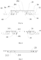
FIG. 1 is a structural schematic view of a secondary battery in accordance with an exemplary embodiment of the present application; -
FIG. 2 is an exploded view of a secondary battery in accordance with an exemplary embodiment of the present application; -
FIG. 3 is a partial schematic view of a secondary battery in accordance with an exemplary embodiment of the present application; -
FIG. 3a is a structural schematic view of a secondary battery in accordance with another exemplary embodiment of the present application; -
FIG. 3b is a structural schematic view of a secondary battery in accordance with still another exemplary embodiment of the present application; -
FIG. 3c is a structural schematic view of a secondary battery in accordance with still another exemplary embodiment of the present application; -
FIG. 4 a partial schematic view of a first sealing piece, a first member, a conductive plate and a top cover plate of a secondary battery in accordance with an exemplary embodiment of the present application; -
FIG. 5 is a structural schematic view of a first sealing piece of a secondary battery in accordance with an exemplary embodiment of the present application; -
FIG. 6 is a sectional view along line A-A inFIG. 3 ; and -
FIG. 7 is another partial schematic view of a secondary battery in accordance with an exemplary embodiment of the present application. -
- 10-top cover plate;
- 101-first through-hole;
- 102-second through-hole;
- 20-connecting plate;
- 201-exhaust hole;
- 202-recess portion;
- 21-first sealing piece;
- 211-first protrusion;
- 212-second protrusion;
- 213-third protrusion;
- 22-second member;
- 30-second terminal assembly;
- 31-conductive block;
- 32-second insulating piece;
- 33-second sealing piece;
- 34-first insulating piece;
- 40-deformable plate;
- 50-conductive plate;
- 60-first member;
- 601-fourth protrusion;
- 70-fixing piece;
- 80-resistance element;
- 90-third sealing piece.
- The drawings herein are incorporated into and constitute a part of the present specification, which show exemplary embodiments in accordance with the present application and explain principles of the present application together with the present description.
- The present application will be further illustrated with reference to the accompanying drawings and embodiments.
- As shown in
FIGS. 1-7 , the present application provides a secondary battery, including a first terminal assembly, a secondterminal assembly 30, atop cover plate 10, an electrode assembly (not shown in figures), adeformable plate 40 and afirst sealing piece 21. The secondary battery further includes a case (not shown in figures). The electrode assembly includes a first electrode plate, a second electrode plate and a separator between the first electrode plate and the second electrode plate. - The
top cover plate 10 seals the case and forms accommodating space together with the case. The electrode assembly is arranged in the accommodating space. At least one of the first terminal assembly and the secondterminal assembly 30 is electrically insulated from thetop cover plate 10. - The first terminal assembly includes a connecting
plate 20 and thedeformable plate 40, and thedeformable plate 40 is attached to the connectingplate 20. The connectingplate 20 is located at a side of thetop cover plate 10 away from the electrode assembly, that is, the connectingplate 20 is outside the accommodating space. Thefirst sealing piece 21 is connected between the connectingplate 20 and thetop cover plate 10. - In a normal state, the first electrode plate is electrically connected with the connecting
plate 20 via thedeformable plate 40, and the second electrode plate is electrically connected with the secondterminal assembly 30. When an internal pressure of the secondary battery exceeds a reference pressure, thedeformable plate 40 can deform to electrically disconnect from the first electrode plate, and thus to electrically disconnect the connectingplate 20 from the first electrode plate. - For the secondary battery in the above exemplary embodiment, by providing the
first sealing piece 21 between the connectingplate 20 and thetop cover plate 10, thefirst sealing piece 21 will not be in direct contact with electrolyte in the accommodating space, which prevents decomposition of the first sealing piece by the electrolyte. Moreover, thefirst sealing piece 21 is outside the secondary battery, which can also reduce risks of thefirst sealing piece 21 being softened by heat produced by a cell during operation, so that service life of thefirst sealing piece 21 can be extended, which guarantees reliability of sealing of the secondary battery. - In order to allow the
deformable plate 40 to be conveniently connected with the first electrode plate, the secondary battery further includes aconductive plate 50, and thetop cover plate 10 is provided with a first through-hole 101. Thedeformable plate 40, theconductive plate 50 and the first through-hole 101 are correspondingly arranged. In a normal state, thedeformable plate 40 is electrically connected with the first electrode plate via theconductive plate 50. - Optionally, the
conductive plate 50 extends through the first through-hole 101, which can reduce the overall height of the first terminal assembly, the secondterminal assembly 30 and thetop cover plate 10, so that the accommodating space which accommodates the electrode assembly can make larger, thereby increasing energy density of the secondary battery. Theconductive plate 50 is insulated from the first through-hole 101, theconductive plate 50 can be directly or indirectly electrically connected with the first through-hole 101. - Generally, the secondary battery further includes a
first member 60, theconductive plate 50 is fixed to thetop cover plate 10 via thefirst member 60, and thefirst member 60 is a conductive piece or an insulating piece. - Generally, the secondary battery further includes a fixing
piece 70, the connectingplate 20 is fixed to thetop cover plate 10 via the fixingpiece 70, and the fixingpiece 70 is not in direct contact with the connectingplate 20 and/or the top cover plate 10 (for example, an insulating sleeve or an insulating layer is provided at a cooperating position between the fixingpiece 70 and the connectingplate 20 and/or the top cover plate 10), especially when the connectingplate 20 is not in direct contact with thetop cover plate 10, reliability of a connection between the connectingplate 20 and thetop cover plate 10 can be improved. When thefirst member 60 is provided, thefirst member 60 is connected with thetop cover plate 10 via the fixingpiece 70, and theconductive plate 50 is connected with thefirst member 60. Specifically, connection manners between the fixingpiece 70 and thetop cover plate 10 and between the fixingpiece 70 and the connectingplate 20 can be implemented as follows: - In a first manner, the fixing
piece 70 and thetop cover plate 10 are formed as an integrated structure, the connectingplate 20 is provided with a third through-hole, the fixingpiece 70 is inserted into the third through-hole and is fixedly riveted to the connectingplate 20, and the fixingpiece 70 is not in direct contact with the connecting plate 20 (for example, an insulating sleeve or an insulating layer is provided at a cooperating position between the fixingpiece 70 and the connecting plate 20), so as to prevent the connectingplate 20 from being electrically conducted with thetop cover plate 10 via the fixingpiece 70. - In a second manner, the
top cover plate 10 is provided with a second through-hole 102, the fixingpiece 70 and the connectingplate 20 are formed as an integrated structure, the fixingpiece 70 is inserted into the second through-hole 102 and is fixedly riveted to thetop cover plate 10, and the fixingpiece 70 is not in direct contact with the top cover plate 10 (for example, an insulating sleeve or an insulating layer is provided at a cooperating position between the fixingpiece 70 and the top cover plate 10), so as to prevent the connectingplate 20 from being electrically conducted with thetop cover plate 10 via the fixingpiece 70. - In a third manner, as shown in
FIGS. 3-3c , the connectingplate 20 is provided with a third through-hole, thetop cover plate 10 is provided with a second through-hole 102, the connectingplate 20 is fixed to thetop cover plate 10 through the fixingpiece 70 extending through the third through-hole and the second through-hole 102. Generally, two ends of the fixingpiece 70 are respectively riveted to the connectingplate 20 and thetop cover plate 10, moreover, the fixingpiece 70 is not in direct contact with the connecting plate 20 (for example, an insulating sleeve or an insulating layer is provided at a cooperating position between the fixingpiece 70 and the connecting plate 20) or the fixingpiece 70 is not in direct contact with the top cover plate 10 (for example, an insulating sleeve or an insulating layer is provided at a cooperating position between the fixingpiece 70 and the top cover plate 10), so as to prevent the connectingplate 20 from being electrically conducted with thetop cover plate 10 via the fixingpiece 70. - The
first sealing piece 21 is formed as a ring-shaped structure, as shown inFIG. 3c , thefirst sealing piece 21 is provided at an outer periphery of the first through-hole 101, when the fixingpiece 70 adopts the second manner or the third manner, the secondary battery further includes athird sealing piece 90, thethird sealing piece 90 is arranged between the fixingpiece 70 and thetop cover plate 10, so as to achieve sealing between the fixingpiece 70 and thetop cover plate 10. - The
first sealing piece 21 can also be formed as a sheet-shaped structure, as shown inFIGS. 3-3b , the connectingplate 20, thefirst sealing piece 21 and thetop cover plate 10 are arranged by stacking. Specifically, thefirst sealing piece 21 is provided with a fourth through-hole, when theconductive plate 50 is provided, theconductive plate 50 extends through the fourth through-hole and is electrically connected with thedeformable plate 40. When the fixingpiece 70 is provided, the fixingpiece 70 is provided at an outer periphery of thefirst sealing piece 21 or provided inside thefirst sealing piece 21. Alternatively, when the fixingpiece 70 is provided, the fixingpiece 70 extends through thefirst sealing piece 21, that is, thefirst sealing piece 21 is provided with a fifth through-hole so that the fixingpiece 70 can extend through, the sheet-shaped first sealingpiece 21 can be implemented by the following manners: - In a first manner, as shown in
FIG. 3a , thefirst sealing piece 21 includes two opposite surfaces, that is, a first surface and a second surface. Both the first surface and the second surface are formed as a planar structure, the first surface is closely contacted with the connectingplate 20, and the second surface is closely contacted with thetop cover plate 10. - In a second manner, as shown in
FIGS. 3 and4 , based on the first manner, afirst protrusion 211 is further provided, and thefirst protrusion 211 protrudes in a direction toward the first electrode plate, that is, the second surface is provided with thefirst protrusion 211, thefirst protrusion 211 extends into the first through-hole 101, and theconductive plate 50 extends through thefirst protrusion 211, so as to improve sealing effect between thetop cover plate 10 and the connectingplate 20, and to prevent poor sealing between thefirst sealing piece 21 and thetop cover plate 10 and between thefirst sealing piece 21 and the connectingplate 20 due to relative sliding. - Since sealing of the
first sealing piece 21 is generally implemented by extrusion, in an extending direction of thetop cover plate 10, a gap is provided between thefirst protrusion 211 and an inner wall of the first through-hole 101, or between thefirst protrusion 211 and theconductive plate 50, so that deforming space is provided for extruding thefirst sealing piece 21 so as to achieve sealing. - In a third manner, as shown in
FIGS. 3 and4 , based on the first manner, asecond protrusion 212 is further provided, and thesecond protrusion 212 protrudes in a direction toward the first electrode plate, that is, the second surface is provided with thesecond protrusion 212, thesecond protrusion 212 extends into the second through-hole 102. The fixingpiece 70 extends through the second through-hole 102 and thesecond protrusion 212, so as to improve sealing effect between thetop cover plate 10 and the fixingpiece 70, moreover, thefirst sealing piece 21 is limited via the protruding structure, thereby preventing poor sealing due to sliding. - In an extending direction of the
top cover plate 10, a gap is provided between thesecond protrusion 212 and an inner wall of the second through-hole 102, or between thesecond protrusion 212 and the fixingpiece 70, so that deforming space is provided for extruding thefirst sealing piece 21 so as to achieve sealing. - In a fourth manner, as shown in
FIG. 3b , based on the first manner, athird protrusion 213 is further provided, and thethird protrusion 213 protrudes in a direction toward the connectingplate 20, thethird protrusion 213 is closely contacted with the connectingplate 20, that is, the first surface is provided with thethird protrusion 213. In this case, the first surface is closely contacted with the connectingplate 20 via thethird protrusion 213, since an area of the first surface is relatively large, and the processing accuracy is not so desirable, it is difficult to achieve total fitting for a large surface area, resulting in poor sealing between the connectingplate 20 and the first surface. By providing thethird protrusion 213, a contact area between the connectingplate 20 and thefirst sealing piece 21 is reduced, thereby improving sealing effect therebetween. One or morethird protrusions 213 is provided, and thethird protrusion 213 is formed as a strip-shaped structure, preferably a closed ring-shaped structure, so as to further improve sealing effect. - Structures of the
first sealing piece 21 shown in the second, third and fourth manners are provided separately, or any two thereof are provided at the same time, as shown inFIGS. 3 and5 , thefirst protrusion 211 and thesecond protrusion 212 are provided at the same time. Or the three structures are provided at the same time, as shown inFIG. 3b , thefirst protrusion 211, thesecond protrusion 212 and thethird protrusion 213 are provided at the same time. - The
first protrusion 211 and thesecond protrusion 212 are provided, along a deforming direction of thedeformable plate 40, thefirst protrusion 211 and thesecond protrusion 212 are closely contacted with thefirst member 60, as shown inFIG. 4 . If thefirst protrusion 211 and thesecond protrusion 212 are not provided, it is possible that metal shaving will remain in a gap defined between thefirst sealing piece 21, thetop cover plate 10, thefirst member 60 and the fixingpiece 70, or remain in a gap defined between thefirst sealing piece 21, thetop cover plate 10, thefirst member 60 and theconductive plate 50, which may result in the fixingpiece 70 or theconductive plate 50 being electrically connected with thetop cover plate 10. Of course, it is also possible that only one of thefirst protrusion 211 and thesecond protrusion 212 is closely contacted with thefirst member 60. - Further, the
first member 60 is provided with afourth protrusion 601 protruding in a direction toward the connectingplate 20, as shown inFIG. 2 , a plurality offourth protrusions 601 is provided, respectively extending into the first through-hole 101 or the second through-hole 102. In order that theconductive plate 50 and the fixingpiece 70 can be better insulated from thetop cover plate 10, thefirst member 60 is made of an insulating material. Moreover, thefirst member 60 is closely contacted with thefirst sealing piece 21, such a structure can better guarantee fitting therebetween, and can also guarantee installation accuracy of thefirst member 60 and theconductive plate 50. - Generally, the connecting
plate 20 and the secondterminal assembly 30 are respectively installed to thetop cover plate 10. In order to facilitate the secondary battery to be electrically connected with an external device, both the connectingplate 20 and the secondterminal assembly 30 extend out of thetop cover plate 10. Further, the secondary battery further includes aconductive block 31, as shown inFIG. 7 , theconductive block 31 is in contact and electrically connected with the secondterminal assembly 30, and the secondterminal assembly 30 is electrically connected with an external device via theconductive block 31, which allows the secondterminal assembly 30 to be conveniently connected with the external device. The first electrode plate is a positive electrode plate (the first terminal assembly is a positive terminal), accordingly, the second electrode plate is a negative electrode plate (the second terminal assembly is a negative terminal). Alternatively, the first electrode plate can also be a negative electrode plate (the first terminal assembly is a negative terminal), and the second electrode plate is a positive electrode (the second terminal assembly is a positive terminal). - In the above exemplary embodiments, both the first terminal assembly and the second
terminal assembly 30 are electrically insulated from thetop cover plate 10; or only one of the first terminal assembly and the secondterminal assembly 30 is electrically insulated from thetop cover plate 10 while the other one thereof is electrically connected with thetop cover plate 10. The electrically connected one is in direct contact and electrically connected with thetop cover plate 10, or indirectly electrically connected with thetop cover plate 10. When the electrically connected one is electrically connected with thetop cover plate 10, usually aresistance element 80 is provided for indirect connection. In order to better reduce loop current when nailing, a resistance value of theresistance element 80 is generally selected to be 1∼100000Ω, such as 1Ω, 50Ω, 100Ω, 5000Ω, 10000Ω, 80000Ω, 100000Ω, etc. Of course, the resistance value of theresistance element 80 can also be selected to be 0.9 Ω, 110000 Ω, etc., the specific selection depends on required resistance value at each position of the loop. Theresistance element 80 can be implemented as follows: - In a first exemplary embodiment, both the
deformable plate 40 and theresistance element 80 are arranged at a same terminal, that is, the first terminal assembly is electrically connected with thetop cover plate 10 via theresistance element 80, and the secondterminal assembly 30 is electrically insulated from thetop cover plate 10, as shown inFIG. 3 . - Specifically, the
conductive block 31 is electrically insulated from thetop cover plate 10 via a second insulatingpiece 32. In order to guarantee sealing between the secondterminal assembly 30 and thetop cover plate 10, usually asecond sealing piece 33 or sealant is adopted for sealing. Insulation between the secondterminal assembly 30 and thetop cover plate 10 is achieved via a first insulatingpiece 34, a sealant or an insulating paint. Thesecond sealing piece 33 and the second insulatingpiece 32 are formed as an integrated structure, that is, thesecond sealing piece 33 is an insulation sealing piece, which can adopt the same structure of thefirst sealing piece 21. - Usually, the connecting
plate 20 is not in direct contact with thetop cover plate 10, and asecond member 22 is provided between the connectingplate 20 and thetop cover plate 10, thesecond member 22 is an insulating piece or a conductive piece. Optionally, thefirst sealing piece 21 and thesecond member 22 are formed as an integrated structure, as shown inFIG. 3 , or, thefirst sealing piece 21 is arranged inside thesecond member 22, as shown inFIG. 3c . Since resistance value of metals is too small, when thesecond member 22 is a conductive piece, material of thesecond member 22 is generally non-metallic material, such as conductive plastic. Arecess portion 202 is provided at a side of the connectingplate 20 close to thetop cover plate 10, so as to provide space for deforming of thedeformable plate 40, as shown inFIGS. 3-3c , therecess portion 202, thedeformable plate 40 and the first through-hole 101 correspond to each other in sequence. Thedeformable plate 40 is provided with deforming space by additionally providing therecess portion 202, which prevents the connectingplate 20 from affecting deforming of thedeformable plate 40, thereby guaranteeing reliability of deforming of thedeformable plate 40, and when an internal pressure of the secondary battery exceeds a reference pressure, an electrical connection between thedeformable plate 40 and the first electrode plate can be timely interrupted. Generally, in the deforming direction of thedeformable plate 40, projection of thedeformable plate 40 is in projection of therecess portion 202. - The
recess portion 202 is formed by recessing from a side of the connectingplate 20 close to thetop cover plate 10 in a direction away from thetop cover plate 10. Along the deforming direction of thedeformable plate 40, therecess portion 202 can penetrate through the connectingplate 20 or can be sealed at a bottom thereof away from thetop cover plate 10. When therecess portion 202 is sealed at the bottom, since when the internal pressure of the secondary battery exceeds the reference pressure and pushes thedeformable plate 40 to deform, as thedeformable plate 40 deforming, gas in therecess portion 202 is extruded and the pressure increases, which prevents thedeformable plate 40 from deforming, or even leads to that thedeformable plate 40 cannot be deformed completely, and thus thedeformable plate 40 may not be disconnected from the first electrode plate. In order to solve this problem, the connectingplate 20 is provided with anexhaust hole 201, theexhaust hole 201 penetrates through the connectingplate 20 along the deforming direction of thedeformable plate 40, and theexhaust hole 201 is opposite to thedeformable plate 40. - The
resistance element 80 is formed as a columnar structure or a sheet-shaped structure. Specifically, theresistance element 80 can be provided in the following manners: - In a first manner, the
resistance element 80 is provided between thetop cover plate 10 and the connectingplate 20, in this case, the connectingplate 20 is not in direct contact with thetop cover plate 10, and the connectingplate 20 is electrically connected with thetop cover plate 10 via theresistance element 80. When thesecond member 22 is provided, theresistance element 80 and thesecond member 22 are formed as an integrated structure, that is, theresistance element 80 and thesecond member 22 are integrated as a whole structure. When thesecond member 22 is an insulating piece, theresistance element 80 extends through thesecond member 22, and two ends of theresistance element 80 are respectively connected with thetop cover plate 10 and the connectingplate 20, generally, theresistance element 80 herein is formed as a columnar structure. Optionally, when thesecond member 22 is a conductive piece, thesecond member 22 and theresistance element 80 adopt the same material, in this case, thesecond member 22 is theresistance element 80, the integrated structure is preferably a sheet-shaped structure, the material can be conductive plastic, that is, theresistance element 80 is formed as a sheet-shaped structure, and the connectingplate 20, theresistance element 80 and thetop cover plate 10 are arranged by stacking, so as to increase reliability of the connection. - When the
conductive plate 50 is provided, theconductive plate 50 is not in contact with thetop cover plate 10, or that theconductive plate 50 is insulated from thetop cover plate 10, as shown inFIG. 4 , by providing thefirst member 60, in this case, thefirst member 60 is an insulating piece. - In a second manner, when the
conductive plate 50 is provided, theresistance element 80 is provided between theconductive plate 50 and thetop cover plate 10, that is, theconductive plate 50 is electrically connected with thetop cover plate 10 via theresistance element 80, which makes the connectingplate 20 be electrically connected with thetop cover plate 10 successively through thedeformable plate 40, theconductive plate 50 and theresistance element 80. In this manner, the connectingplate 20 is not directly electrically conducted with thetop cover plate 10. As a result, the connectingplate 20 needs to be insulated from thetop cover plate 10. In order to ensure the connectingplate 20 is insulated from thetop cover plate 10, thesecond member 22 or thefirst sealing piece 21 is an insulating piece, or, an insulating glue or an insulating paint is arranged between the connectingplate 20 and thetop cover plate 10. - Optionally, the
resistance element 80 is formed as a columnar structure, when theconductive plate 50 is inserted into the first through-hole 101, theresistance element 80 is arranged between the inner wall of the first through-hole and theconductive plate 50. Optionally, theresistance element 80 can also be arranged at a side of thetop cover plate 10 close to the electrode assembly. Thefirst member 60 and theresistance element 80 are formed as an integrated structure, that is, thefirst member 60 and theresistance element 80 are integrated as a whole structure. When thefirst member 60 is an insulating piece, theresistance element 80 extends through thefirst member 60, and two ends of theresistance element 80 are respectively connected with theconductive plate 50 and thetop cover plate 10; when thefirst member 60 is a conductive plate, thefirst member 60 and theresistance element 80 are formed by adopting the same material (such as conductive plastic), in this case, thefirst member 60 is theresistance element 80. - In a second exemplary embodiment, the
deformable plate 40 and theresistance element 80 are arranged at different terminals, that is, the secondterminal assembly 30 is electrically connected with thetop cover plate 10 via theresistance element 80; and the first terminal assembly is electrically insulated from thetop cover plate 10. The connectingplate 20 is electrically insulated from thetop cover plate 10 via asecond member 22, theconductive plate 50 is electrically insulated from thetop cover plate 10 via thefirst member 60, in this case, thesecond member 22 and thefirst member 60 are both insulating pieces. - The above description only illustrates the preferred embodiments of the present application and is not intended to limit the present application, and various modifications and variations may be made by those skilled in the art. However, any modifications, equivalent substitutions, improvements and the like within the principles of the present application shall be included in the protection scope of the present application.
Claims (10)
- A secondary battery, characterized in that, comprising a first terminal assembly, a second terminal assembly, a top cover plate, an electrode assembly and a first sealing piece, wherein
the electrode assembly comprises a first electrode plate, a second electrode plate and a separator between the first electrode plate and the second electrode plate;
at least one of the first terminal assembly and the second terminal assembly is electrically insulated from the top cover plate;
the first terminal assembly comprises a connecting plate and a deformable plate, the connecting plate is located at a side of the top cover plate away from the electrode assembly, and the deformable plate is attached to the connecting plate;
the first sealing piece is connected between the connecting plate and the top cover plate;
in a normal state, the first electrode plate is electrically connected with the connecting plate via the deformable plate, and the second electrode plate is electrically connected with the second terminal assembly; and
the deformable plate is configured to deform to electrically disconnect from the first electrode plate when an internal pressure of the secondary battery exceeds a reference pressure. - The secondary battery according to claim 1, characterized in that, further comprising a fixing piece, wherein the connecting plate is fixed to the top cover plate via the fixing piece.
- The secondary battery according to claim 2, characterized in that, the fixing piece extends through the first sealing piece.
- The secondary battery according to claim 3, characterized in that, the top cover plate is provided with a second through-hole, and the first sealing piece is provided with a second protrusion, the second protrusion extends into the second through-hole; and the fixing piece extends through the second through-hole and the second protrusion.
- The secondary battery according to claim 3, characterized in that, further comprising a conductive plate, wherein the top cover plate is provided with a first through-hole; the deformable plate, the conductive plate and the first through-hole are correspondingly arranged; the first sealing piece is arranged along an outer periphery of the first through-hole; and
in a normal state, the deformable plate is electrically connected with the first electrode plate via the conductive plate. - The secondary battery according to claim 5, characterized in that, the conductive plate extends through the first through-hole, the conductive plate comprises a stepped surface facing toward the connecting plate, and the first sealing piece overlaps the stepped surface.
- The secondary battery according to claim 5, characterized in that, the first sealing piece is provided with a first protrusion protruding in a direction toward the first electrode plate, the first protrusion extends into the first through-hole, and the conductive plate extends through the first protrusion.
- The secondary battery according to claim 7, characterized in that, further comprising a first member, wherein the conductive plate is connected with the first member, and the first member is fixed to the top cover plate via the fixing piece.
- The secondary battery according to claim 8, characterized in that, along a deforming direction of the deformable plate, the first protrusion is closely contacted with the first member.
- The secondary battery according to any one of claims 1-9, characterized in that, further comprising a resistance element;
the second terminal assembly is electrically insulated from the top cover plate; and
the first terminal assembly is electrically connected with the top cover plate via the resistance element.
Applications Claiming Priority (1)
| Application Number | Priority Date | Filing Date | Title |
|---|---|---|---|
| CN201611130362.8A CN108232052B (en) | 2016-12-09 | 2016-12-09 | Secondary battery |
Publications (2)
| Publication Number | Publication Date |
|---|---|
| EP3333931A1 true EP3333931A1 (en) | 2018-06-13 |
| EP3333931B1 EP3333931B1 (en) | 2020-05-20 |
Family
ID=59738264
Family Applications (1)
| Application Number | Title | Priority Date | Filing Date |
|---|---|---|---|
| EP17188328.3A Active EP3333931B1 (en) | 2016-12-09 | 2017-08-29 | Secondary battery |
Country Status (4)
| Country | Link |
|---|---|
| US (1) | US10601001B2 (en) |
| EP (1) | EP3333931B1 (en) |
| JP (1) | JP6574471B2 (en) |
| CN (2) | CN108232052B (en) |
Families Citing this family (6)
| Publication number | Priority date | Publication date | Assignee | Title |
|---|---|---|---|---|
| CN108428822B (en) | 2017-08-30 | 2023-10-20 | 宁德时代新能源科技股份有限公司 | Top cap subassembly and secondary cell of secondary cell |
| CN207124215U (en) * | 2017-09-07 | 2018-03-20 | 宁德时代新能源科技股份有限公司 | The cap assembly and secondary cell of secondary cell |
| CN108428826B (en) * | 2018-01-18 | 2023-12-29 | 宁德时代新能源科技股份有限公司 | Secondary battery top cover components, secondary batteries, and automobiles |
| CN110176557B (en) * | 2019-04-09 | 2024-04-05 | 宁德时代新能源科技股份有限公司 | Secondary battery and top cover assembly thereof |
| JP7656027B2 (en) * | 2020-09-30 | 2025-04-02 | 寧徳新能源科技有限公司 | Battery Cell and Feed-Through Assembly |
| EP4207476A4 (en) * | 2020-09-30 | 2024-08-14 | Ningde Amperex Technology Limited | BATTERY CELL AND FEEDTHROUGH ARRANGEMENT |
Citations (3)
| Publication number | Priority date | Publication date | Assignee | Title |
|---|---|---|---|---|
| US20130196185A1 (en) * | 2012-01-27 | 2013-08-01 | Sanyo Electric Co., Ltd. | Prismatic secondary battery |
| US20150243961A1 (en) * | 2012-09-28 | 2015-08-27 | Hitachi Automotive Systems, Ltd. | Rectangular secondary battery |
| CN205666265U (en) * | 2016-06-07 | 2016-10-26 | 宁德时代新能源科技股份有限公司 | Power battery top cap and power battery |
Family Cites Families (20)
| Publication number | Priority date | Publication date | Assignee | Title |
|---|---|---|---|---|
| KR100349908B1 (en) * | 1999-12-15 | 2002-08-22 | 삼성에스디아이 주식회사 | Prismatic type sealed battery |
| CN2502406Y (en) * | 2001-09-07 | 2002-07-24 | 深圳市比亚迪锂电池有限公司 | Lithium ionic cell |
| JP3756096B2 (en) * | 2001-10-02 | 2006-03-15 | Necトーキン栃木株式会社 | Sealed battery |
| CN101257098B (en) * | 2007-03-02 | 2012-01-25 | 深圳市比克电池有限公司 | Battery and battery seal component convenient for assembling |
| JP5538114B2 (en) | 2010-07-20 | 2014-07-02 | 日立ビークルエナジー株式会社 | Secondary battery |
| WO2012048652A1 (en) * | 2010-10-16 | 2012-04-19 | Byd Company Limited | Lithium-ion battery |
| CN103620825B (en) * | 2011-07-27 | 2015-12-02 | 丰田自动车株式会社 | Enclosed-type battery |
| KR101274909B1 (en) * | 2011-07-29 | 2013-06-17 | 로베르트 보쉬 게엠베하 | Rechargeable battery |
| JP5821969B2 (en) * | 2011-11-23 | 2015-11-24 | トヨタ自動車株式会社 | Secondary battery manufacturing method and secondary battery |
| JP5712954B2 (en) * | 2012-03-13 | 2015-05-07 | 株式会社豊田自動織機 | Power storage device and vehicle |
| JP2013191355A (en) * | 2012-03-13 | 2013-09-26 | Sanyo Electric Co Ltd | Secondary battery cell, power supply device, and vehicle and power storage device incorporating power supply device |
| JP6163783B2 (en) * | 2013-02-28 | 2017-07-19 | 三洋電機株式会社 | Rectangular secondary battery and manufacturing method thereof |
| KR101686279B1 (en) * | 2013-06-19 | 2016-12-13 | 삼성에스디아이 주식회사 | Secondary battery |
| JP6235435B2 (en) | 2014-08-25 | 2017-11-22 | 日立オートモティブシステムズ株式会社 | Secondary battery |
| CN204760444U (en) * | 2015-07-30 | 2015-11-11 | 宁德时代新能源科技有限公司 | Secondary cell top cap and secondary cell |
| CN204991821U (en) * | 2015-09-09 | 2016-01-20 | 丰田自动车株式会社 | Secondary battery |
| KR102555490B1 (en) * | 2015-10-06 | 2023-07-12 | 삼성에스디아이 주식회사 | Rechargeable battery pack |
| CN105870375B (en) * | 2016-06-07 | 2018-07-10 | 宁德时代新能源科技股份有限公司 | Power battery top cap and power battery |
| CN106025114B (en) * | 2016-06-07 | 2018-10-09 | 宁德时代新能源科技股份有限公司 | Power battery top cap and power battery |
| CN105932181B (en) * | 2016-07-15 | 2018-09-28 | 东莞永蓝电子科技有限公司 | Power battery top cap and use power battery of this top cap |
-
2016
- 2016-12-09 CN CN201611130362.8A patent/CN108232052B/en active Active
- 2016-12-09 CN CN201911169509.8A patent/CN111081916B/en active Active
-
2017
- 2017-08-24 US US15/686,075 patent/US10601001B2/en active Active
- 2017-08-29 EP EP17188328.3A patent/EP3333931B1/en active Active
- 2017-11-20 JP JP2017222653A patent/JP6574471B2/en active Active
Patent Citations (3)
| Publication number | Priority date | Publication date | Assignee | Title |
|---|---|---|---|---|
| US20130196185A1 (en) * | 2012-01-27 | 2013-08-01 | Sanyo Electric Co., Ltd. | Prismatic secondary battery |
| US20150243961A1 (en) * | 2012-09-28 | 2015-08-27 | Hitachi Automotive Systems, Ltd. | Rectangular secondary battery |
| CN205666265U (en) * | 2016-06-07 | 2016-10-26 | 宁德时代新能源科技股份有限公司 | Power battery top cap and power battery |
Also Published As
| Publication number | Publication date |
|---|---|
| CN111081916B (en) | 2022-11-08 |
| JP6574471B2 (en) | 2019-09-11 |
| JP2018098189A (en) | 2018-06-21 |
| US10601001B2 (en) | 2020-03-24 |
| EP3333931B1 (en) | 2020-05-20 |
| CN108232052B (en) | 2020-12-11 |
| CN111081916A (en) | 2020-04-28 |
| CN108232052A (en) | 2018-06-29 |
| US20180166666A1 (en) | 2018-06-14 |
Similar Documents
| Publication | Publication Date | Title |
|---|---|---|
| EP3333931A1 (en) | Secondary battery | |
| US10665827B2 (en) | Cap assembly for a second battery and second battery | |
| JP5539910B2 (en) | Secondary battery | |
| KR102246736B1 (en) | Rechargeable battery | |
| KR102177503B1 (en) | Secondary Battery | |
| KR101265202B1 (en) | Secondary battery | |
| WO2020063584A1 (en) | Top cover assembly, manufacturing method for same, top cover manufacturing method, and battery cell | |
| US10673056B2 (en) | Secondary battery | |
| KR20160024311A (en) | Rechargeable battery module | |
| KR101074780B1 (en) | Cap assembly, can, and secondary battery using the same | |
| CN115939611A (en) | End cap assemblies, energy storage devices and consumers | |
| US20140272520A1 (en) | Battery module | |
| EP2849263B1 (en) | Rechargeable battery | |
| EP2899779B1 (en) | Secondary battery | |
| CN103943809A (en) | Secondary battery | |
| CN104953075A (en) | Secondary battery | |
| KR102531183B1 (en) | Rechargeable battery module | |
| US10529974B2 (en) | Secondary battery | |
| EP3477731B1 (en) | Rechargeable battery | |
| KR101711983B1 (en) | Rechargeable battery | |
| US20150349317A1 (en) | Rechargeable battery | |
| KR101733745B1 (en) | Rechargeable battery | |
| EP3001481B1 (en) | Rechargeable battery | |
| CN110931665A (en) | Battery with a battery cell |
Legal Events
| Date | Code | Title | Description |
|---|---|---|---|
| PUAI | Public reference made under article 153(3) epc to a published international application that has entered the european phase |
Free format text: ORIGINAL CODE: 0009012 |
|
| STAA | Information on the status of an ep patent application or granted ep patent |
Free format text: STATUS: THE APPLICATION HAS BEEN PUBLISHED |
|
| AK | Designated contracting states |
Kind code of ref document: A1 Designated state(s): AL AT BE BG CH CY CZ DE DK EE ES FI FR GB GR HR HU IE IS IT LI LT LU LV MC MK MT NL NO PL PT RO RS SE SI SK SM TR |
|
| AX | Request for extension of the european patent |
Extension state: BA ME |
|
| STAA | Information on the status of an ep patent application or granted ep patent |
Free format text: STATUS: REQUEST FOR EXAMINATION WAS MADE |
|
| 17P | Request for examination filed |
Effective date: 20180905 |
|
| RBV | Designated contracting states (corrected) |
Designated state(s): AL AT BE BG CH CY CZ DE DK EE ES FI FR GB GR HR HU IE IS IT LI LT LU LV MC MK MT NL NO PL PT RO RS SE SI SK SM TR |
|
| STAA | Information on the status of an ep patent application or granted ep patent |
Free format text: STATUS: EXAMINATION IS IN PROGRESS |
|
| 17Q | First examination report despatched |
Effective date: 20190313 |
|
| GRAP | Despatch of communication of intention to grant a patent |
Free format text: ORIGINAL CODE: EPIDOSNIGR1 |
|
| STAA | Information on the status of an ep patent application or granted ep patent |
Free format text: STATUS: GRANT OF PATENT IS INTENDED |
|
| INTG | Intention to grant announced |
Effective date: 20200130 |
|
| GRAS | Grant fee paid |
Free format text: ORIGINAL CODE: EPIDOSNIGR3 |
|
| GRAA | (expected) grant |
Free format text: ORIGINAL CODE: 0009210 |
|
| STAA | Information on the status of an ep patent application or granted ep patent |
Free format text: STATUS: THE PATENT HAS BEEN GRANTED |
|
| AK | Designated contracting states |
Kind code of ref document: B1 Designated state(s): AL AT BE BG CH CY CZ DE DK EE ES FI FR GB GR HR HU IE IS IT LI LT LU LV MC MK MT NL NO PL PT RO RS SE SI SK SM TR |
|
| REG | Reference to a national code |
Ref country code: GB Ref legal event code: FG4D |
|
| REG | Reference to a national code |
Ref country code: CH Ref legal event code: EP |
|
| REG | Reference to a national code |
Ref country code: DE Ref legal event code: R096 Ref document number: 602017016961 Country of ref document: DE |
|
| REG | Reference to a national code |
Ref country code: AT Ref legal event code: REF Ref document number: 1273204 Country of ref document: AT Kind code of ref document: T Effective date: 20200615 |
|
| RAP2 | Party data changed (patent owner data changed or rights of a patent transferred) |
Owner name: CONTEMPORARY AMPEREX TECHNOLOGY CO., LIMITED |
|
| REG | Reference to a national code |
Ref country code: LT Ref legal event code: MG4D |
|
| REG | Reference to a national code |
Ref country code: NL Ref legal event code: MP Effective date: 20200520 |
|
| PG25 | Lapsed in a contracting state [announced via postgrant information from national office to epo] |
Ref country code: PT Free format text: LAPSE BECAUSE OF FAILURE TO SUBMIT A TRANSLATION OF THE DESCRIPTION OR TO PAY THE FEE WITHIN THE PRESCRIBED TIME-LIMIT Effective date: 20200921 Ref country code: NO Free format text: LAPSE BECAUSE OF FAILURE TO SUBMIT A TRANSLATION OF THE DESCRIPTION OR TO PAY THE FEE WITHIN THE PRESCRIBED TIME-LIMIT Effective date: 20200820 Ref country code: IS Free format text: LAPSE BECAUSE OF FAILURE TO SUBMIT A TRANSLATION OF THE DESCRIPTION OR TO PAY THE FEE WITHIN THE PRESCRIBED TIME-LIMIT Effective date: 20200920 Ref country code: GR Free format text: LAPSE BECAUSE OF FAILURE TO SUBMIT A TRANSLATION OF THE DESCRIPTION OR TO PAY THE FEE WITHIN THE PRESCRIBED TIME-LIMIT Effective date: 20200821 Ref country code: LT Free format text: LAPSE BECAUSE OF FAILURE TO SUBMIT A TRANSLATION OF THE DESCRIPTION OR TO PAY THE FEE WITHIN THE PRESCRIBED TIME-LIMIT Effective date: 20200520 Ref country code: SE Free format text: LAPSE BECAUSE OF FAILURE TO SUBMIT A TRANSLATION OF THE DESCRIPTION OR TO PAY THE FEE WITHIN THE PRESCRIBED TIME-LIMIT Effective date: 20200520 Ref country code: FI Free format text: LAPSE BECAUSE OF FAILURE TO SUBMIT A TRANSLATION OF THE DESCRIPTION OR TO PAY THE FEE WITHIN THE PRESCRIBED TIME-LIMIT Effective date: 20200520 |
|
| REG | Reference to a national code |
Ref country code: DE Ref legal event code: R079 Ref document number: 602017016961 Country of ref document: DE Free format text: PREVIOUS MAIN CLASS: H01M0002060000 Ipc: H01M0050172000 |
|
| PG25 | Lapsed in a contracting state [announced via postgrant information from national office to epo] |
Ref country code: BG Free format text: LAPSE BECAUSE OF FAILURE TO SUBMIT A TRANSLATION OF THE DESCRIPTION OR TO PAY THE FEE WITHIN THE PRESCRIBED TIME-LIMIT Effective date: 20200820 Ref country code: HR Free format text: LAPSE BECAUSE OF FAILURE TO SUBMIT A TRANSLATION OF THE DESCRIPTION OR TO PAY THE FEE WITHIN THE PRESCRIBED TIME-LIMIT Effective date: 20200520 Ref country code: LV Free format text: LAPSE BECAUSE OF FAILURE TO SUBMIT A TRANSLATION OF THE DESCRIPTION OR TO PAY THE FEE WITHIN THE PRESCRIBED TIME-LIMIT Effective date: 20200520 Ref country code: RS Free format text: LAPSE BECAUSE OF FAILURE TO SUBMIT A TRANSLATION OF THE DESCRIPTION OR TO PAY THE FEE WITHIN THE PRESCRIBED TIME-LIMIT Effective date: 20200520 |
|
| REG | Reference to a national code |
Ref country code: AT Ref legal event code: MK05 Ref document number: 1273204 Country of ref document: AT Kind code of ref document: T Effective date: 20200520 |
|
| PG25 | Lapsed in a contracting state [announced via postgrant information from national office to epo] |
Ref country code: AL Free format text: LAPSE BECAUSE OF FAILURE TO SUBMIT A TRANSLATION OF THE DESCRIPTION OR TO PAY THE FEE WITHIN THE PRESCRIBED TIME-LIMIT Effective date: 20200520 Ref country code: NL Free format text: LAPSE BECAUSE OF FAILURE TO SUBMIT A TRANSLATION OF THE DESCRIPTION OR TO PAY THE FEE WITHIN THE PRESCRIBED TIME-LIMIT Effective date: 20200520 |
|
| PG25 | Lapsed in a contracting state [announced via postgrant information from national office to epo] |
Ref country code: AT Free format text: LAPSE BECAUSE OF FAILURE TO SUBMIT A TRANSLATION OF THE DESCRIPTION OR TO PAY THE FEE WITHIN THE PRESCRIBED TIME-LIMIT Effective date: 20200520 Ref country code: DK Free format text: LAPSE BECAUSE OF FAILURE TO SUBMIT A TRANSLATION OF THE DESCRIPTION OR TO PAY THE FEE WITHIN THE PRESCRIBED TIME-LIMIT Effective date: 20200520 Ref country code: ES Free format text: LAPSE BECAUSE OF FAILURE TO SUBMIT A TRANSLATION OF THE DESCRIPTION OR TO PAY THE FEE WITHIN THE PRESCRIBED TIME-LIMIT Effective date: 20200520 Ref country code: RO Free format text: LAPSE BECAUSE OF FAILURE TO SUBMIT A TRANSLATION OF THE DESCRIPTION OR TO PAY THE FEE WITHIN THE PRESCRIBED TIME-LIMIT Effective date: 20200520 Ref country code: CZ Free format text: LAPSE BECAUSE OF FAILURE TO SUBMIT A TRANSLATION OF THE DESCRIPTION OR TO PAY THE FEE WITHIN THE PRESCRIBED TIME-LIMIT Effective date: 20200520 Ref country code: IT Free format text: LAPSE BECAUSE OF FAILURE TO SUBMIT A TRANSLATION OF THE DESCRIPTION OR TO PAY THE FEE WITHIN THE PRESCRIBED TIME-LIMIT Effective date: 20200520 Ref country code: EE Free format text: LAPSE BECAUSE OF FAILURE TO SUBMIT A TRANSLATION OF THE DESCRIPTION OR TO PAY THE FEE WITHIN THE PRESCRIBED TIME-LIMIT Effective date: 20200520 Ref country code: SM Free format text: LAPSE BECAUSE OF FAILURE TO SUBMIT A TRANSLATION OF THE DESCRIPTION OR TO PAY THE FEE WITHIN THE PRESCRIBED TIME-LIMIT Effective date: 20200520 |
|
| REG | Reference to a national code |
Ref country code: DE Ref legal event code: R097 Ref document number: 602017016961 Country of ref document: DE |
|
| PG25 | Lapsed in a contracting state [announced via postgrant information from national office to epo] |
Ref country code: SK Free format text: LAPSE BECAUSE OF FAILURE TO SUBMIT A TRANSLATION OF THE DESCRIPTION OR TO PAY THE FEE WITHIN THE PRESCRIBED TIME-LIMIT Effective date: 20200520 Ref country code: PL Free format text: LAPSE BECAUSE OF FAILURE TO SUBMIT A TRANSLATION OF THE DESCRIPTION OR TO PAY THE FEE WITHIN THE PRESCRIBED TIME-LIMIT Effective date: 20200520 |
|
| PLBE | No opposition filed within time limit |
Free format text: ORIGINAL CODE: 0009261 |
|
| STAA | Information on the status of an ep patent application or granted ep patent |
Free format text: STATUS: NO OPPOSITION FILED WITHIN TIME LIMIT |
|
| PG25 | Lapsed in a contracting state [announced via postgrant information from national office to epo] |
Ref country code: MC Free format text: LAPSE BECAUSE OF FAILURE TO SUBMIT A TRANSLATION OF THE DESCRIPTION OR TO PAY THE FEE WITHIN THE PRESCRIBED TIME-LIMIT Effective date: 20200520 |
|
| REG | Reference to a national code |
Ref country code: CH Ref legal event code: PL |
|
| 26N | No opposition filed |
Effective date: 20210223 |
|
| PG25 | Lapsed in a contracting state [announced via postgrant information from national office to epo] |
Ref country code: CH Free format text: LAPSE BECAUSE OF NON-PAYMENT OF DUE FEES Effective date: 20200831 Ref country code: LI Free format text: LAPSE BECAUSE OF NON-PAYMENT OF DUE FEES Effective date: 20200831 Ref country code: LU Free format text: LAPSE BECAUSE OF NON-PAYMENT OF DUE FEES Effective date: 20200829 |
|
| REG | Reference to a national code |
Ref country code: BE Ref legal event code: MM Effective date: 20200831 |
|
| PG25 | Lapsed in a contracting state [announced via postgrant information from national office to epo] |
Ref country code: SI Free format text: LAPSE BECAUSE OF FAILURE TO SUBMIT A TRANSLATION OF THE DESCRIPTION OR TO PAY THE FEE WITHIN THE PRESCRIBED TIME-LIMIT Effective date: 20200520 |
|
| PG25 | Lapsed in a contracting state [announced via postgrant information from national office to epo] |
Ref country code: IE Free format text: LAPSE BECAUSE OF NON-PAYMENT OF DUE FEES Effective date: 20200829 Ref country code: BE Free format text: LAPSE BECAUSE OF NON-PAYMENT OF DUE FEES Effective date: 20200831 |
|
| REG | Reference to a national code |
Ref country code: DE Ref legal event code: R082 Ref document number: 602017016961 Country of ref document: DE Representative=s name: ROESLER-RASCH-VAN DER HEIDE & PARTNER PATENT- , DE |
|
| PG25 | Lapsed in a contracting state [announced via postgrant information from national office to epo] |
Ref country code: TR Free format text: LAPSE BECAUSE OF FAILURE TO SUBMIT A TRANSLATION OF THE DESCRIPTION OR TO PAY THE FEE WITHIN THE PRESCRIBED TIME-LIMIT Effective date: 20200520 Ref country code: MT Free format text: LAPSE BECAUSE OF FAILURE TO SUBMIT A TRANSLATION OF THE DESCRIPTION OR TO PAY THE FEE WITHIN THE PRESCRIBED TIME-LIMIT Effective date: 20200520 Ref country code: CY Free format text: LAPSE BECAUSE OF FAILURE TO SUBMIT A TRANSLATION OF THE DESCRIPTION OR TO PAY THE FEE WITHIN THE PRESCRIBED TIME-LIMIT Effective date: 20200520 |
|
| PG25 | Lapsed in a contracting state [announced via postgrant information from national office to epo] |
Ref country code: MK Free format text: LAPSE BECAUSE OF FAILURE TO SUBMIT A TRANSLATION OF THE DESCRIPTION OR TO PAY THE FEE WITHIN THE PRESCRIBED TIME-LIMIT Effective date: 20200520 |
|
| P01 | Opt-out of the competence of the unified patent court (upc) registered |
Effective date: 20230516 |
|
| REG | Reference to a national code |
Ref country code: DE Ref legal event code: R082 Ref document number: 602017016961 Country of ref document: DE Ref country code: DE Ref legal event code: R081 Ref document number: 602017016961 Country of ref document: DE Owner name: CONTEMPORARY AMPEREX TECHNOLOGY (HONG KONG) LI, HK Free format text: FORMER OWNER: CONTEMPORARY AMPEREX TECHNOLOGY CO., LIMITED, CITY FUJIAN, JIAOCHENG DISTRICT NINGDE, CN |
|
| REG | Reference to a national code |
Ref country code: GB Ref legal event code: 732E Free format text: REGISTERED BETWEEN 20240808 AND 20240814 |
|
| PGFP | Annual fee paid to national office [announced via postgrant information from national office to epo] |
Ref country code: DE Payment date: 20250702 Year of fee payment: 9 |
|
| PGFP | Annual fee paid to national office [announced via postgrant information from national office to epo] |
Ref country code: GB Payment date: 20250703 Year of fee payment: 9 |
|
| PGFP | Annual fee paid to national office [announced via postgrant information from national office to epo] |
Ref country code: FR Payment date: 20250703 Year of fee payment: 9 |