EP3333879A1 - Discharge lamp, vehicle lighting device, and vehicle lamp - Google Patents
Discharge lamp, vehicle lighting device, and vehicle lamp Download PDFInfo
- Publication number
- EP3333879A1 EP3333879A1 EP17186160.2A EP17186160A EP3333879A1 EP 3333879 A1 EP3333879 A1 EP 3333879A1 EP 17186160 A EP17186160 A EP 17186160A EP 3333879 A1 EP3333879 A1 EP 3333879A1
- Authority
- EP
- European Patent Office
- Prior art keywords
- discharge lamp
- lamp
- discharge
- circuit
- low beam
- Prior art date
- Legal status (The legal status is an assumption and is not a legal conclusion. Google has not performed a legal analysis and makes no representation as to the accuracy of the status listed.)
- Granted
Links
Images

Classifications
-
- H—ELECTRICITY
- H01—ELECTRIC ELEMENTS
- H01J—ELECTRIC DISCHARGE TUBES OR DISCHARGE LAMPS
- H01J61/00—Gas-discharge or vapour-discharge lamps
- H01J61/02—Details
- H01J61/04—Electrodes; Screens; Shields
- H01J61/06—Main electrodes
- H01J61/073—Main electrodes for high-pressure discharge lamps
- H01J61/0732—Main electrodes for high-pressure discharge lamps characterised by the construction of the electrode
-
- H—ELECTRICITY
- H01—ELECTRIC ELEMENTS
- H01J—ELECTRIC DISCHARGE TUBES OR DISCHARGE LAMPS
- H01J61/00—Gas-discharge or vapour-discharge lamps
- H01J61/02—Details
- H01J61/12—Selection of substances for gas fillings; Specified operating pressure or temperature
- H01J61/125—Selection of substances for gas fillings; Specified operating pressure or temperature having an halogenide as principal component
-
- H—ELECTRICITY
- H01—ELECTRIC ELEMENTS
- H01J—ELECTRIC DISCHARGE TUBES OR DISCHARGE LAMPS
- H01J61/00—Gas-discharge or vapour-discharge lamps
- H01J61/02—Details
- H01J61/30—Vessels; Containers
- H01J61/34—Double-wall vessels or containers
-
- H—ELECTRICITY
- H01—ELECTRIC ELEMENTS
- H01J—ELECTRIC DISCHARGE TUBES OR DISCHARGE LAMPS
- H01J61/00—Gas-discharge or vapour-discharge lamps
- H01J61/82—Lamps with high-pressure unconstricted discharge having a cold pressure > 400 Torr
- H01J61/827—Metal halide arc lamps
-
- H—ELECTRICITY
- H05—ELECTRIC TECHNIQUES NOT OTHERWISE PROVIDED FOR
- H05B—ELECTRIC HEATING; ELECTRIC LIGHT SOURCES NOT OTHERWISE PROVIDED FOR; CIRCUIT ARRANGEMENTS FOR ELECTRIC LIGHT SOURCES, IN GENERAL
- H05B41/00—Circuit arrangements or apparatus for igniting or operating discharge lamps
- H05B41/14—Circuit arrangements
- H05B41/36—Controlling
- H05B41/38—Controlling the intensity of light
- H05B41/40—Controlling the intensity of light discontinuously
- H05B41/42—Controlling the intensity of light discontinuously in two steps only
Definitions
- Embodiments described herein relate generally to a discharge lamp, a vehicle lighting device, and a vehicle lamp.
- a discharge lamp including a light emitting portion having a discharge space in which a discharge medium is sealed on an inside thereof, and a pair of electrodes protruding into the discharge space and disposed to face each other at a predetermined distance.
- a light source for low beam (beam for passing) and a light source for high beam (beam for driving) are provided in a headlamp for an automobile, and the low beam and the high beam are switched as necessary.
- a discharge lamp is used as the light source for low beam and another discharge lamp or another type of lamp is used for the light source for high beam.
- the low beam and the high beam are necessary for an operation of the automobile, since two light sources are necessary, a manufacturing cost of the headlamp is increased, and a size or design of the headlamp is limited.
- a discharge lamp in which a light emitting portion is moved in a predetermined direction so that the discharge lamp can cope with both the low beam and the high beam.
- a discharge lamp including a magnetic field generating unit for applying a magnetic field including a magnetic force line component is also proposed.
- a discharge lamp includes a light emitting portion that has a discharge space in which a metal halide and inert gas are sealed on an inside thereof; and a pair of electrodes that protrudes to an inside of the discharge space and faces each other at a predetermined distance.
- Electric power applied to the discharge lamp during a low beam is 24 W or more and 30 W or less
- electric power applied to the discharge lamp during a high beam is 32 W or more and 38 W or less.
- a thickness dimension of the electrode satisfies the following formula where the thickness dimension of the electrode is d (mm). 0.24 mm ⁇ d mm ⁇ 0.33 mm
- the discharge lamp according to the embodiments can be, for example, a High Intensity Discharge (HID) lamp used for a headlamp of an automobile.
- HID High Intensity Discharge
- the discharge lamp is the HID lamp used for the headlamp of the automobile, so-called horizontal lighting can be performed.
- the discharge lamp according to the embodiments is used for the headlamp of the automobile.
- the discharge lamp according to the embodiments may be used for other purposes.
- a case where the discharge lamp according to the embodiments is the HID lamp used for the headlamp of the automobile is exemplified.
- FIG. 1 is a schematic view illustrating a discharge lamp 100 according to an embodiment.
- a forward direction is a front end side
- a rearward direction is a rear end side
- an upward direction is an upper end side
- a downward direction is a lower end side.
- the discharge lamp 100 is provided with a burner 101 and a socket 102.
- the burner 101 is provided with an outer tube 5, an inner tube 1, an electrode mount 3, a support wire 35, a sleeve 4, and a metal band 71.
- the outer tube 5 is provided coaxially with the inner tube 1 on an outside of the inner tube 1. That is, the burner 101 has a double-tube structure configured of the outer tube 5 and the inner tube 1.
- the outer tube 5 is joined (welded) to the vicinity of a cylindrical portion 14 of the inner tube 1.
- Gas is sealed in a closed space formed between the inner tube 1 and the outer tube 5.
- the sealed gas may be gas capable of performing dielectric barrier discharge.
- the outer tube 5 is formed of a material having a thermal expansion coefficient close to a thermal expansion coefficient of a material of the inner tube 1 and having ultraviolet blocking properties.
- the outer tube 5 can be formed from, for example, quartz glass doped with an oxide such as titanium, cerium, or aluminum.
- the inner tube 1 has a light emitting portion 11, a sealing portion 12, a boundary portion 13, and the cylindrical portion 14.
- the light emitting portion 11, the sealing portion 12, the boundary portion 13, and the cylindrical portion 14 can be integrally formed.
- the inner tube 1 (light emitting portion 11, the sealing portion 12, the boundary portion 13, and the cylindrical portion 14) is formed of a material having translucency and heat resistance.
- the inner tube 1 can be formed of, for example, quartz glass or the like.
- the light emitting portion 11 has a substantially elliptical outer shape.
- the light emitting portion 11 is provided in the vicinity of a center of the inner tube 1.
- a dimension (spherical length) of the light emitting portion 11 in an axial direction of the inner tube 1 can be, for example, substantially 8 mm.
- a dimension of the light emitting portion 11 in a direction orthogonal to the axial direction of the inner tube 1 can be, for example, substantially 6 mm.
- a discharge space 111 is provided on an inside of the light emitting portion 11.
- a center portion of the discharge space 111 has a substantially cylindrical shape. Both end portions of the discharge space 111 have a substantially conical shape.
- a discharge medium is sealed in the discharge space 111.
- the discharge medium contains a metal halide 2 and an inert gas.
- the discharge medium is substantially free of mercury.
- the phrase "substantially free of mercury” includes not only mercury but also mercury contained in an extent of impurities.
- the discharge medium may contain mercury if it is less than 2 mg/cc in the discharge space 111.
- the metal halide 2 can be, for example, a halide of scandium, a halide of indium, a halide of sodium, and a halide of zinc.
- Illustrative examples of the halogen include iodine. However, instead of iodine, bromine, chlorine, or the like can be used.
- the inert gas sealed in the discharge space 111 may be, for example, xenon.
- xenon besides xenon, neon, argon, krypton, or the like can be used, or a mixed gas of these can also be used.
- the inert gas is xenon.
- the sealing portion 12 has a form of a plate and is joined to both end portions of the light emitting portion 11.
- the sealing portion 12 can be formed, for example, by using a pinch seal method.
- the sealing portion 12 may be formed by a shrink seal method, and may have a cylindrical shape.
- the cylindrical portion 14 is joined to one sealing portion 12 via the boundary portion 13.
- the boundary portion 13 and the cylindrical portion 14 are joined to an end portion of the sealing portion 12 on a side opposite to a light emitting portion 11 side.
- the electrode mount 3 is provided on an inside of the sealing portion 12.
- the electrode mount 3 has a metal foil 31, an electrode 32, a coil 33, and a lead wire 34. Two sets of the electrode mount 3 (metal foil 31, the electrode 32, the coil 33, and the lead wire 34) are provided.
- the metal foil 31 is provided on the inside of the sealing portion 12.
- the metal foil 31 is joined to the vicinity of an end portion of the electrode 32 on a side opposite to the discharge space 111 side.
- the metal foil 31 has a form of a thin plate and can be made of, for example, molybdenum, rhenium molybdenum, tungsten, rhenium tungsten, or the like.
- the electrode 32 has a cylindrical shape.
- One end portion of the electrode 32 protrudes into the discharge space 111. That is, one end of the electrode 32 is provided on the inside of the discharge space 111 and the other end is provided on the inside of the sealing portion 12. A pair of the electrodes 32 is provided so as to face each other at a predetermined distance. The other end of the electrode 32 is joined to the vicinity of an end portion of the metal foil 31 on the light emitting portion 11 side. Joining between the electrode 32 and the metal foil 31 can be performed by, for example, laser welding.
- the electrode 32 can be formed of, for example, pure tungsten, doped tungsten, rhenium tungsten, or the like.
- the electrode 32 may contain thorium or may not contain thorium.
- the coil 33 is provided to suppress occurrence of cracks in the sealing portion 12.
- the coil 33 can be formed from, for example, a metal wire made of doped tungsten.
- the coil 33 is provided on the inside of the sealing portion 12.
- the coil 33 is wound around an outside of the electrode 32.
- a wire diameter of the coil 33 is substantially 30 ⁇ m to substantially 100 ⁇ m and a coil pitch can be 600% or less.
- the lead wire 34 has a linear shape.
- a cross-sectional shape of the lead wire 34 can be, for example, circular.
- the lead wire 34 can be formed of, for example, molybdenum or the like.
- One end portion of the lead wire 34 is joined to the vicinity of an end portion of the metal foil 31 on a side opposite to the light emitting portion 11 side. Joining between the lead wire 34 and the metal foil 31 can be performed by laser welding.
- the other end of the lead wire 34 extends to the outside of the inner tube 1.
- the support wire 35 has an L shape and is joined to an end portion of the lead wire 34 extending from a front end side of the discharge lamp 100. Joining between the support wire 35 and the lead wire 34 can be performed by laser welding.
- the support wire 35 can be formed of, for example, nickel.
- the sleeve 4 covers a portion of the support wire 35 extending parallel to the inner tube 1.
- the sleeve 4 has, for example, a cylindrical shape.
- the sleeve 4 can be formed of, for example, ceramics.
- the metal band 71 is fixed to the vicinity of an end portion of the outer tube 5 on a rear end side.
- the socket 102 has a body portion 61, an attachment fitting 72, a bottom terminal 81, and a side terminal 82.
- the body portion 61 is formed of an insulating material such as resin.
- a rear end side of the lead wire 34, a rear end side of the support wire 35, and a rear end side of the sleeve 4 are provided on an inside of the body portion 61.
- the attachment fitting 72 is provided at an end portion of the body portion 61.
- the attachment fitting 72 is provided on a front end side of the body portion 61.
- the attachment fitting 72 protrudes from the body portion 61.
- the attachment fitting 72 holds the metal band 71.
- the metal band 71 is held by the attachment fitting 72 so that the burner 101 is held in the socket 102.
- the bottom terminal 81 is provided on the inside of the body portion 61.
- the bottom terminal 81 is provided on a rear end side of the body portion 61.
- the bottom terminal 81 is formed of a conductive material.
- the bottom terminal 81 is electrically connected to the lead wire 34.
- the side terminal 82 is provided at a side wall of the body portion 61.
- the side terminal 82 is provided on the rear end side of the body portion 61.
- the side terminal 82 is formed of a conductive material.
- the side terminal 82 is electrically connected to the support wire 35.
- the bottom terminal 81 and the side terminal 82 are electrically connected to a lighting circuit 301.
- the bottom terminal 81 is electrically connected to a high voltage side of the lighting circuit 301.
- the side terminal 82 is electrically connected to a low voltage side of the lighting circuit 301.
- the discharge lamp 100 is used for the headlamp of the automobile, the discharge lamp 100 is attached such that a center axis (tube axis) thereof is in a substantially horizontal state and the support wire 35 is positioned on a substantially lower end side (downward). Moreover, turning on the discharge lamp 100 attached in such a direction is referred to as horizontal lighting.
- one discharge lamp 100 can cope with both the low beam and the high beam, it is possible to reduce a manufacturing cost of the headlamp. In addition, it is possible to reduce the size of the headlamp, or to increase a degree of freedom of design of the headlamp.
- the electrode 32 may suffer severe consumption, crack leakage is likely to occur in the sealing portion 12, and there is a concern that the service life of the discharge lamp 100 is shortened.
- electric power (electric power during stable lighting) applied to the discharge lamp 100 during the low beam is 24 W or more and 30 W or less
- the thickness dimension (diameter dimension) d of the electrode 32 is set as follows
- electric power (electric power during stable lighting) applied to the discharge lamp 100 during the high beam is 32 W or more and 38 W or less
- Table 1 is a table illustrating a relationship between the thickness dimension (diameter dimension) d of the electrode 32 and the occurrence of the flickering, and the service life.
- Table 1 Thickness dimension of electrode d (mm) 0.22 0.24 0.28 0.33 0.35 Flickering during low beam ⁇ ⁇ ⁇ ⁇ X Flickering during high beam X ⁇ ⁇ ⁇ ⁇ Service life X ⁇ ⁇ ⁇ ⁇ Determination X ⁇ ⁇ ⁇ X
- an internal volume (volume of the discharge space 111) of the light emitting portion 11 was 22 ⁇ L.
- the inert gas sealed in the discharge space 111 was xenon.
- a weight of the metal halide 2 was 0.4 mg.
- a material of the electrode 32 was tungsten.
- An applied electric power during the low beam was 27 W.
- An applied electric power during the high beam was 34 W.
- the thickness dimension (diameter dimension) d of the electrode 32 is set as the following formula, even if electric power applied to the discharge lamp 100 is changed, it is possible to suppress the occurrence of the flickering and to suppress shortening of the service life.
- the discharge lamp 100 capable of coping with the low beam and the high beam can be formed with a simple configuration. 0.24 mm ⁇ d mm ⁇ 0.33 mm
- Table 2 is a table illustrating a relationship between an amount of a change in a tube current during switching between the low beam and the high beam, and the occurrence of the flickering.
- Table 2 Thickness dimension of electrode d (mm) Conditions Amount of change in tube current (A) 0.4 0.3 0.2 0.1 0.24 Flickering during low beam ⁇ ⁇ ⁇ ⁇ Flickering during high beam X ⁇ ⁇ ⁇ 0.28 Flickering during low beam X ⁇ ⁇ ⁇ Flickering during high beam X ⁇ ⁇ ⁇ 0.33 Flickering during low beam X ⁇ ⁇ ⁇ Flickering during high beam ⁇ ⁇ ⁇ ⁇ Determination X ⁇ ⁇ ⁇ ⁇
- the discharge lamp 100 capable of coping with the low beam and the high beam can be formed with a simple configuration.
- the amount of the change in the tube current when switching between the low beam and the high beam can be 0.3 A or less.
- Table 3 is a table illustrating a relationship between a cross-sectional area of a current, the occurrence of the flickering, and the service life.
- Table 3 Cross-sectional area of current I/S (A/mm 2 ) 6 8 12 14 16 18 20 Items Flickering during low beam X ⁇ ⁇ ⁇ ⁇ ⁇ ⁇ Flickering during high beam ⁇ ⁇ ⁇ ⁇ ⁇ X Service life ⁇ ⁇ ⁇ ⁇ ⁇ X Determination X ⁇ ⁇ ⁇ ⁇ ⁇ X
- I(A) is a current applied to the discharge lamp 100
- S (mm 2 ) is a cross-sectional area of the electrode 32
- I/S (A/mm 2 ) is a cross-sectional area of a current.
- the discharge lamp 100 capable of coping with the low beam and the high beam can be formed with a simple configuration. 8.0 A / mm 2 ⁇ I / S A / mm 2 ⁇ 18.0 A / mm 2
- the cross-sectional area (I/S) of the current can be set so as to be in the range described above.
- the arc spot can be stabilized if the distance (distance between the electrodes) L1 between tips of the pair of the electrodes 32 satisfies the following formula. Therefore, the occurrence of the flickering can be suppressed. 3.0 mm ⁇ L 1 mm ⁇ 3.6 mm
- the gas sealed in the closed space formed between the inner tube 1 and the outer tube 5 is either nitrogen, argon, or a mixed gas of nitrogen and argon, and a sealing pressure of the gas is 0.1 atm or less at room temperature (25°C). In this way, it is possible to make the temperature of the light emitting portion 11 within an appropriate range. Therefore, it is possible to suppress the occurrence of the flickering and to suppress shortening of the service life thereof.
- the gas sealed in the discharge space 111 is xenon and the sealing pressure of the gas is 10 atm or more and 15 atm or less at room temperature (25°C). In this way, the arc spot can be stabilized. Therefore, the occurrence of the flickering can be suppressed.
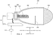
- FIG. 2 is a schematic view illustrating a vehicle lamp 200 and a vehicle lighting device 300.
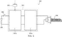
- FIG. 3 is a block view of the vehicle lighting device 300.
- FIG. 2 illustrates a case where the discharge lamp 100 is attached such that the pair of the electrodes 32 provided in the discharge lamp 100 is horizontal. That is, a case of the discharge lamp 100 to be horizontal lighting is illustrated.
- the vehicle lighting device 300 is provided with the discharge lamp 100, the lighting circuit 301, and a changeover switch 302.
- the vehicle lamp 200 is provided with the vehicle lighting device 300, a housing 202, a light shielding control plate 203, and a lens 204.
- the housing 202 reflects the light irradiated from the discharge lamp 100 to the front end side.
- the housing 202 is formed of, for example, a metal having high reflectance.
- a space is provided on an inside of the housing 202 and an inner surface has a parabolic shape.
- a front end side and a rear end side of the housing 202 are opened.
- the discharge lamp 100 is attached to the housing 202.
- the socket 102 of the discharge lamp 100 is attached to the vicinity of the opening of the rear end side of the housing 202.
- the burner 101 of the discharge lamp 100 is positioned at the space on the inside of the housing 202.
- the housing 202 has a function of holding the discharge lamp 100 and a function of a reflector.
- the light shielding control plate 203 is provided on the inside of the housing 202 and is provided on the front end side of the burner 101 and on a lower end side of the burner 101.
- the light shielding control plate 203 is formed of a light shielding material such as a metal.
- the light shielding control plate 203 is provided to form a light distribution called a cut line.
- the light shielding control plate 203 is movable.
- the lens 204 is provided so as to close the opening on the front end side of the housing 202.
- the lens 204 can be a convex lens.
- the lens 204 condenses the light directly incident from the discharge lamp 100 and the light reflected and incident by the housing 202 to form a desired light distribution.
- the lighting circuit 301 is a circuit for starting of the discharge lamp 100 and maintaining the lighting.
- the lighting circuit 301 may include, for example, an igniter circuit 301a and a ballast circuit 301b.
- a DC power source DS such as a battery and a switch SW are electrically connected to an input side of the lighting circuit 301.
- the discharge lamp 100 is electrically connected to an output side of the lighting circuit 301.
- the igniter circuit 301a is composed of, for example, a transformer, a capacitor, a resistor, a semiconductor element, and the like.
- the igniter circuit 301a generates a high voltage pulse of substantially 30 kV and applies the high voltage pulse to the discharge lamp 100. Insulation breakdown occurs between the pair of electrodes 32 and electric discharge occurs by applying a high voltage pulse of substantially 30 kV to the discharge lamp 100. That is, the igniter circuit 301a starts the discharge lamp 100.
- the ballast circuit 301b maintains the lighting of the discharge lamp 100 started by the igniter circuit 301a.
- the ballast circuit 301b has a low beam ballast circuit and a high beam ballast circuit.
- Each of the low beam ballast circuit and the high beam ballast circuit has, for example, a DC/DC conversion circuit, a DC/AC conversion circuit, a current and voltage detection circuit, a control circuit, and the like.
- the low beam ballast circuit applies electric power of 24 W or more and 30 W or less to the discharge lamp 100 during stable lighting.
- the high beam ballast circuit applies electric power of 32 W or more and 38 W or less to the discharge lamp 100 during stable lighting.
- the changeover switch 302 performs switching between the low beam and the high beam based on an input by a driver or the like. That is, the changeover switch 302 switches the low beam ballast circuit and high beam ballast circuit based on an input by the driver or the like. Therefore, predetermined electric power is supplied from the low beam ballast circuit or high beam ballast circuit switched by the changeover switch 302 to the discharge lamp 100.
- the vehicle lighting device 300 has the discharge lamp 100 and an igniter circuit 301a incorporated in a case, and a ballast circuit 301b and a changeover switch 302 as other circuits are electrically connected to the igniter circuit 301a, but the configuration is not limited thereto.
- the vehicle lighting device 300 has the igniter circuit 301a and the ballast circuit 301b incorporated in one case, and the discharge lamp 100, and the changeover switch 302 as another circuit may be electrically connected to the ballast circuit 301b.
- the vehicle lighting device 300 has the igniter circuit 301a, the ballast circuit 301b, and the changeover switch 302 incorporated in one case, and those may be electrically connected to the discharge lamp 100.
- the vehicle lighting device 300 only has the discharge lamp 100 and the igniter circuit 301a, the ballast circuit 301b, and the changeover switch 302 as other circuits may be electrically connected to the discharge lamp 100.
Landscapes
- Non-Portable Lighting Devices Or Systems Thereof (AREA)
- Lighting Device Outwards From Vehicle And Optical Signal (AREA)
- Circuit Arrangements For Discharge Lamps (AREA)
- Discharge Lamp (AREA)
- Discharge Lamps And Accessories Thereof (AREA)
Abstract

Description
- Embodiments described herein relate generally to a discharge lamp, a vehicle lighting device, and a vehicle lamp.
- There is a discharge lamp including a light emitting portion having a discharge space in which a discharge medium is sealed on an inside thereof, and a pair of electrodes protruding into the discharge space and disposed to face each other at a predetermined distance.
- Here, in general, a light source for low beam (beam for passing) and a light source for high beam (beam for driving) are provided in a headlamp for an automobile, and the low beam and the high beam are switched as necessary. For example, a discharge lamp is used as the light source for low beam and another discharge lamp or another type of lamp is used for the light source for high beam.
- Although the low beam and the high beam are necessary for an operation of the automobile, since two light sources are necessary, a manufacturing cost of the headlamp is increased, and a size or design of the headlamp is limited.
- For this reason, it is preferable to be able to cope with both the low beam and the high beam with one discharge lamp. Therefore, a discharge lamp is proposed in which a light emitting portion is moved in a predetermined direction so that the discharge lamp can cope with both the low beam and the high beam. In addition, a discharge lamp including a magnetic field generating unit for applying a magnetic field including a magnetic force line component is also proposed.
- However, in such a manner, a configuration of the discharge lamp becomes complicated.
- Therefore, it is desired to develop a discharge lamp capable of coping with low beam and high beam with a simple configuration.
-
-
FIG. 1 is a schematic view illustrating a discharge lamp according to an embodiment. -
FIG. 2 is a schematic view illustrating a vehicle lamp and a vehicle lighting device. -
FIG. 3 is a block view of the vehicle lighting device. - In general, according to one embodiment, a discharge lamp includes a light emitting portion that has a discharge space in which a metal halide and inert gas are sealed on an inside thereof; and a pair of electrodes that protrudes to an inside of the discharge space and faces each other at a predetermined distance.
- Electric power applied to the discharge lamp during a low beam is 24 W or more and 30 W or less, and electric power applied to the discharge lamp during a high beam is 32 W or more and 38 W or less. A thickness dimension of the electrode satisfies the following formula where the thickness dimension of the electrode is d (mm).

- Hereinafter, embodiments will be described with reference to the drawings.
- The discharge lamp according to the embodiments can be, for example, a High Intensity Discharge (HID) lamp used for a headlamp of an automobile. In addition, for example, if the discharge lamp is the HID lamp used for the headlamp of the automobile, so-called horizontal lighting can be performed.
- It is preferable that the discharge lamp according to the embodiments is used for the headlamp of the automobile. However, the discharge lamp according to the embodiments may be used for other purposes. Here, a case where the discharge lamp according to the embodiments is the HID lamp used for the headlamp of the automobile is exemplified.
-
FIG. 1 is a schematic view illustrating adischarge lamp 100 according to an embodiment. - Moreover, in
FIG. 1 , if thedischarge lamp 100 is attached to an automobile, a forward direction is a front end side, a rearward direction is a rear end side, an upward direction is an upper end side, and a downward direction is a lower end side. - As illustrated in
FIG. 1 , thedischarge lamp 100 is provided with aburner 101 and asocket 102. - The
burner 101 is provided with anouter tube 5, aninner tube 1, anelectrode mount 3, asupport wire 35, a sleeve 4, and ametal band 71. - The
outer tube 5 is provided coaxially with theinner tube 1 on an outside of theinner tube 1. That is, theburner 101 has a double-tube structure configured of theouter tube 5 and theinner tube 1. Theouter tube 5 is joined (welded) to the vicinity of acylindrical portion 14 of theinner tube 1. - Gas is sealed in a closed space formed between the
inner tube 1 and theouter tube 5. The sealed gas may be gas capable of performing dielectric barrier discharge. - Moreover, the sealed gas will be described below in detail.
- It is preferable that the
outer tube 5 is formed of a material having a thermal expansion coefficient close to a thermal expansion coefficient of a material of theinner tube 1 and having ultraviolet blocking properties. Theouter tube 5 can be formed from, for example, quartz glass doped with an oxide such as titanium, cerium, or aluminum. - The
inner tube 1 has alight emitting portion 11, a sealingportion 12, aboundary portion 13, and thecylindrical portion 14. Thelight emitting portion 11, thesealing portion 12, theboundary portion 13, and thecylindrical portion 14 can be integrally formed. - The inner tube 1 (
light emitting portion 11, thesealing portion 12, theboundary portion 13, and the cylindrical portion 14) is formed of a material having translucency and heat resistance. Theinner tube 1 can be formed of, for example, quartz glass or the like. - The
light emitting portion 11 has a substantially elliptical outer shape. Thelight emitting portion 11 is provided in the vicinity of a center of theinner tube 1. A dimension (spherical length) of thelight emitting portion 11 in an axial direction of theinner tube 1 can be, for example, substantially 8 mm. A dimension of thelight emitting portion 11 in a direction orthogonal to the axial direction of theinner tube 1 can be, for example, substantially 6 mm. - A
discharge space 111 is provided on an inside of thelight emitting portion 11. A center portion of thedischarge space 111 has a substantially cylindrical shape. Both end portions of thedischarge space 111 have a substantially conical shape. - A discharge medium is sealed in the
discharge space 111. The discharge medium contains ametal halide 2 and an inert gas. - In addition, from the viewpoint of environmental protection, the discharge medium is substantially free of mercury. Moreover, in the present specification, the phrase "substantially free of mercury" includes not only mercury but also mercury contained in an extent of impurities. For example, the discharge medium may contain mercury if it is less than 2 mg/cc in the
discharge space 111. - The
metal halide 2 can be, for example, a halide of scandium, a halide of indium, a halide of sodium, and a halide of zinc. Illustrative examples of the halogen include iodine. However, instead of iodine, bromine, chlorine, or the like can be used. - The inert gas sealed in the
discharge space 111 may be, for example, xenon. In addition, besides xenon, neon, argon, krypton, or the like can be used, or a mixed gas of these can also be used. However, it is more preferable that the inert gas is xenon. - The sealing
portion 12 has a form of a plate and is joined to both end portions of thelight emitting portion 11. The sealingportion 12 can be formed, for example, by using a pinch seal method. In addition, the sealingportion 12 may be formed by a shrink seal method, and may have a cylindrical shape. Thecylindrical portion 14 is joined to one sealingportion 12 via theboundary portion 13. - The
boundary portion 13 and thecylindrical portion 14 are joined to an end portion of the sealingportion 12 on a side opposite to alight emitting portion 11 side. - The
electrode mount 3 is provided on an inside of the sealingportion 12. - The
electrode mount 3 has ametal foil 31, anelectrode 32, acoil 33, and alead wire 34. Two sets of the electrode mount 3 (metal foil 31, theelectrode 32, thecoil 33, and the lead wire 34) are provided. - The
metal foil 31 is provided on the inside of the sealingportion 12. Themetal foil 31 is joined to the vicinity of an end portion of theelectrode 32 on a side opposite to thedischarge space 111 side. - The
metal foil 31 has a form of a thin plate and can be made of, for example, molybdenum, rhenium molybdenum, tungsten, rhenium tungsten, or the like. - The
electrode 32 has a cylindrical shape. - One end portion of the
electrode 32 protrudes into thedischarge space 111. That is, one end of theelectrode 32 is provided on the inside of thedischarge space 111 and the other end is provided on the inside of the sealingportion 12. A pair of theelectrodes 32 is provided so as to face each other at a predetermined distance. The other end of theelectrode 32 is joined to the vicinity of an end portion of themetal foil 31 on thelight emitting portion 11 side. Joining between theelectrode 32 and themetal foil 31 can be performed by, for example, laser welding. - The
electrode 32 can be formed of, for example, pure tungsten, doped tungsten, rhenium tungsten, or the like. Theelectrode 32 may contain thorium or may not contain thorium. - The
coil 33 is provided to suppress occurrence of cracks in the sealingportion 12. Thecoil 33 can be formed from, for example, a metal wire made of doped tungsten. Thecoil 33 is provided on the inside of the sealingportion 12. Thecoil 33 is wound around an outside of theelectrode 32. For example, a wire diameter of thecoil 33 is substantially 30 µm to substantially 100 µm and a coil pitch can be 600% or less. - The
lead wire 34 has a linear shape. A cross-sectional shape of thelead wire 34 can be, for example, circular. Thelead wire 34 can be formed of, for example, molybdenum or the like. One end portion of thelead wire 34 is joined to the vicinity of an end portion of themetal foil 31 on a side opposite to thelight emitting portion 11 side. Joining between thelead wire 34 and themetal foil 31 can be performed by laser welding. The other end of thelead wire 34 extends to the outside of theinner tube 1. - The
support wire 35 has an L shape and is joined to an end portion of thelead wire 34 extending from a front end side of thedischarge lamp 100. Joining between thesupport wire 35 and thelead wire 34 can be performed by laser welding. Thesupport wire 35 can be formed of, for example, nickel. - The sleeve 4 covers a portion of the
support wire 35 extending parallel to theinner tube 1. The sleeve 4 has, for example, a cylindrical shape. The sleeve 4 can be formed of, for example, ceramics. - The
metal band 71 is fixed to the vicinity of an end portion of theouter tube 5 on a rear end side. - The
socket 102 has abody portion 61, an attachment fitting 72, abottom terminal 81, and aside terminal 82. - The
body portion 61 is formed of an insulating material such as resin. A rear end side of thelead wire 34, a rear end side of thesupport wire 35, and a rear end side of the sleeve 4 are provided on an inside of thebody portion 61. - The attachment fitting 72 is provided at an end portion of the
body portion 61. The attachment fitting 72 is provided on a front end side of thebody portion 61. The attachment fitting 72 protrudes from thebody portion 61. The attachment fitting 72 holds themetal band 71. Themetal band 71 is held by the attachment fitting 72 so that theburner 101 is held in thesocket 102. - The
bottom terminal 81 is provided on the inside of thebody portion 61. Thebottom terminal 81 is provided on a rear end side of thebody portion 61. Thebottom terminal 81 is formed of a conductive material. Thebottom terminal 81 is electrically connected to thelead wire 34. - The
side terminal 82 is provided at a side wall of thebody portion 61. Theside terminal 82 is provided on the rear end side of thebody portion 61. Theside terminal 82 is formed of a conductive material. Theside terminal 82 is electrically connected to thesupport wire 35. - The
bottom terminal 81 and theside terminal 82 are electrically connected to alighting circuit 301. In this case, thebottom terminal 81 is electrically connected to a high voltage side of thelighting circuit 301. Theside terminal 82 is electrically connected to a low voltage side of thelighting circuit 301. - If the
discharge lamp 100 is used for the headlamp of the automobile, thedischarge lamp 100 is attached such that a center axis (tube axis) thereof is in a substantially horizontal state and thesupport wire 35 is positioned on a substantially lower end side (downward). Moreover, turning on thedischarge lamp 100 attached in such a direction is referred to as horizontal lighting. - Here, if one
discharge lamp 100 can cope with both the low beam and the high beam, it is possible to reduce a manufacturing cost of the headlamp. In addition, it is possible to reduce the size of the headlamp, or to increase a degree of freedom of design of the headlamp. - In this case, if electric power applied to the
discharge lamp 100 is changed, it is possible to cope with both the low beam and the high beam. However, if the applied electric power is changed, the temperature of theelectrode 32 is likely to fall outside an appropriate range. In this case, since an arc spot becomes unstable even if the temperature of theelectrode 32 is too high or too low, flickering occurs. When flickering occurs, it causes discomfort to a driver and other people. - In addition, furthermore, if the temperature of the
electrode 32 is too high, theelectrode 32 may suffer severe consumption, crack leakage is likely to occur in the sealingportion 12, and there is a concern that the service life of thedischarge lamp 100 is shortened. - As a result of studies, the inventor found that if electric power (electric power during stable lighting) applied to the
discharge lamp 100 during the low beam is 24 W or more and 30 W or less, and the thickness dimension (diameter dimension) d of theelectrode 32 is set as follows, electric power (electric power during stable lighting) applied to thedischarge lamp 100 during the high beam is 32 W or more and 38 W or less, it is possible to suppress the occurrence of the flickering and to suppress shortening of the service life thereof. - Table 1 is a table illustrating a relationship between the thickness dimension (diameter dimension) d of the
electrode 32 and the occurrence of the flickering, and the service life.Table 1 Thickness dimension of electrode d (mm) 0.22 0.24 0.28 0.33 0.35 Flickering during low beam ○ ○ ○ ○ X Flickering during high beam X ○ ○ ○ ○ Service life X ○ ○ ○ ○ Determination X ○ ○ ○ X - Moreover, an internal volume (volume of the discharge space 111) of the
light emitting portion 11 was 22 µL. - The inert gas sealed in the
discharge space 111 was xenon. - A composition ratio of the
metal halide 2 was ScI3:NaI:ZnI2:InBr=45wt%:49wt%:4.9wt%:0.1wt%. - A weight of the
metal halide 2 was 0.4 mg. - A material of the
electrode 32 was tungsten. - An applied electric power during the low beam was 27 W.
- An applied electric power during the high beam was 34 W.
- Suppression of the occurrence of the flickering was evaluated by obtaining a fluctuation rate of illuminance. The illuminance was measured every 0.5 seconds from 5 minutes to 10 minutes. A case where the fluctuation rate of the illuminance was 3% or less was indicated by "O", and a case where the fluctuation rate of the illuminance exceeded 3% was indicated by "X".
- In the evaluation of the service life, a case where the
discharge lamp 100 was lit for 2,000 hours in a flashing mode of an EU 120 minute mode, and a crack leak did not occur in the sealingportion 12 was indicated by "O", and a case where the crack leak occurred in the sealingportion 12 was indicated by "X". - As can be seen from Table 1, if the thickness dimension (diameter dimension) d of the
electrode 32 is set as the following formula, even if electric power applied to thedischarge lamp 100 is changed, it is possible to suppress the occurrence of the flickering and to suppress shortening of the service life. - That is, the
discharge lamp 100 capable of coping with the low beam and the high beam can be formed with a simple configuration.
- Moreover, in Table 1, although the applied electric power during the low beam was 27 W and the applied electric power during the high beam was 34 W, even if the applied electric power during the low beam is 24 W or more and 30 W or less, and the applied electric power during the high beam is 32 W or more and 38 W or less, it is possible to obtain the same effect.
- Table 2 is a table illustrating a relationship between an amount of a change in a tube current during switching between the low beam and the high beam, and the occurrence of the flickering.
Table 2 Thickness dimension of electrode d (mm) Conditions Amount of change in tube current (A) 0.4 0.3 0.2 0.1 0.24 Flickering during low beam ○ ○ ○ ○ Flickering during high beam X ○ ○ ○ 0.28 Flickering during low beam X ○ ○ ○ Flickering during high beam X ○ ○ ○ 0.33 Flickering during low beam X ○ ○ ○ Flickering during high beam ○ ○ ○ ○ Determination X ○ ○ ○ - Moreover, conditions and evaluation references of the evaluation test are the same as those of the case of Table 1.
- As can be seen from Table 2, if the amount of the change in the tube current when switching between the low beam and the high beam is 0.3 A or less, the occurrence of the flickering can be suppressed even if the electric power applied to the
discharge lamp 100 is changed. - That is, the
discharge lamp 100 capable of coping with the low beam and the high beam can be formed with a simple configuration. - Moreover, if the thickness dimension of the
electrode 32 is set to 0.24 (mm)≤d (mm)≤0.33 (mm), the electric power applied to thedischarge lamp 100 during the low beam is set to 24 W or more and 30 W or less, and the electric power applied to thedischarge lamp 100 during the high beam is set to 32 W or more and 38 W or less, the amount of the change in the tube current when switching between the low beam and the high beam can be 0.3 A or less. - Table 3 is a table illustrating a relationship between a cross-sectional area of a current, the occurrence of the flickering, and the service life.
Table 3 Cross-sectional area of current I/S (A/mm2) 6 8 12 14 16 18 20 Items Flickering during low beam X ○ ○ ○ ○ ○ ○ Flickering during high beam ○ ○ ○ ○ ○ ○ X Service life ○ ○ ○ ○ ○ ○ X Determination X ○ ○ ○ ○ ○ X - Moreover, conditions and evaluation references of the evaluation test are the same as those of the case of Table 1.
- In Table 3, I(A) is a current applied to the
discharge lamp 100, S (mm2) is a cross-sectional area of theelectrode 32, and I/S (A/mm2) is a cross-sectional area of a current. - As can be seen from Table 3, if the following formula is satisfied, it is possible to suppress the occurrence of the flickering and to suppress shortening of the service life thereof even if electric power applied to the
discharge lamp 100 is changed. - That is, the
discharge lamp 100 capable of coping with the low beam and the high beam can be formed with a simple configuration.
- Moreover, if the thickness dimension of the
electrode 32 is 0.24 (mm) ≤d (mm) ≤0.33 (mm), electric power applied to thedischarge lamp 100 during the low beam is 24 W or more and 30 W or less, and electric power applied to thedischarge lamp 100 during the high beam is 32 W or more and 38 W or less, the cross-sectional area (I/S) of the current can be set so as to be in the range described above. - In addition, according to the findings obtained by the inventor, the arc spot can be stabilized if the distance (distance between the electrodes) L1 between tips of the pair of the
electrodes 32 satisfies the following formula. Therefore, the occurrence of the flickering can be suppressed.
- In addition, according to the findings obtained by the inventor, it is preferable that the gas sealed in the closed space formed between the
inner tube 1 and theouter tube 5 is either nitrogen, argon, or a mixed gas of nitrogen and argon, and a sealing pressure of the gas is 0.1 atm or less at room temperature (25°C). In this way, it is possible to make the temperature of thelight emitting portion 11 within an appropriate range. Therefore, it is possible to suppress the occurrence of the flickering and to suppress shortening of the service life thereof. - In addition, according to the findings obtained by the inventor, it is preferable that the gas sealed in the
discharge space 111 is xenon and the sealing pressure of the gas is 10 atm or more and 15 atm or less at room temperature (25°C). In this way, the arc spot can be stabilized. Therefore, the occurrence of the flickering can be suppressed. -
FIG. 2 is a schematic view illustrating avehicle lamp 200 and avehicle lighting device 300.FIG. 3 is a block view of thevehicle lighting device 300. -
FIG. 2 illustrates a case where thedischarge lamp 100 is attached such that the pair of theelectrodes 32 provided in thedischarge lamp 100 is horizontal. That is, a case of thedischarge lamp 100 to be horizontal lighting is illustrated. - As illustrated in
FIGS. 2 and3 , thevehicle lighting device 300 is provided with thedischarge lamp 100, thelighting circuit 301, and achangeover switch 302. - As illustrated in
FIG. 2 , thevehicle lamp 200 is provided with thevehicle lighting device 300, ahousing 202, a lightshielding control plate 203, and alens 204. - The
housing 202 reflects the light irradiated from thedischarge lamp 100 to the front end side. Thehousing 202 is formed of, for example, a metal having high reflectance. A space is provided on an inside of thehousing 202 and an inner surface has a parabolic shape. - A front end side and a rear end side of the
housing 202 are opened. - The
discharge lamp 100 is attached to thehousing 202. Thesocket 102 of thedischarge lamp 100 is attached to the vicinity of the opening of the rear end side of thehousing 202. Theburner 101 of thedischarge lamp 100 is positioned at the space on the inside of thehousing 202. - That is, the
housing 202 has a function of holding thedischarge lamp 100 and a function of a reflector. - The light
shielding control plate 203 is provided on the inside of thehousing 202 and is provided on the front end side of theburner 101 and on a lower end side of theburner 101. - The light
shielding control plate 203 is formed of a light shielding material such as a metal. The lightshielding control plate 203 is provided to form a light distribution called a cut line. The lightshielding control plate 203 is movable. - The
lens 204 is provided so as to close the opening on the front end side of thehousing 202. Thelens 204 can be a convex lens. Thelens 204 condenses the light directly incident from thedischarge lamp 100 and the light reflected and incident by thehousing 202 to form a desired light distribution. - The
lighting circuit 301 is a circuit for starting of thedischarge lamp 100 and maintaining the lighting. - As illustrated in
FIG. 3 , thelighting circuit 301 may include, for example, anigniter circuit 301a and aballast circuit 301b. - A DC power source DS such as a battery and a switch SW are electrically connected to an input side of the
lighting circuit 301. Thedischarge lamp 100 is electrically connected to an output side of thelighting circuit 301. - The
igniter circuit 301a is composed of, for example, a transformer, a capacitor, a resistor, a semiconductor element, and the like. Theigniter circuit 301a generates a high voltage pulse of substantially 30 kV and applies the high voltage pulse to thedischarge lamp 100. Insulation breakdown occurs between the pair ofelectrodes 32 and electric discharge occurs by applying a high voltage pulse of substantially 30 kV to thedischarge lamp 100. That is, theigniter circuit 301a starts thedischarge lamp 100. - The
ballast circuit 301b maintains the lighting of thedischarge lamp 100 started by theigniter circuit 301a. - In addition, the
ballast circuit 301b has a low beam ballast circuit and a high beam ballast circuit. Each of the low beam ballast circuit and the high beam ballast circuit has, for example, a DC/DC conversion circuit, a DC/AC conversion circuit, a current and voltage detection circuit, a control circuit, and the like. The low beam ballast circuit applies electric power of 24 W or more and 30 W or less to thedischarge lamp 100 during stable lighting. The high beam ballast circuit applies electric power of 32 W or more and 38 W or less to thedischarge lamp 100 during stable lighting. - The
changeover switch 302 performs switching between the low beam and the high beam based on an input by a driver or the like. That is, thechangeover switch 302 switches the low beam ballast circuit and high beam ballast circuit based on an input by the driver or the like. Therefore, predetermined electric power is supplied from the low beam ballast circuit or high beam ballast circuit switched by thechangeover switch 302 to thedischarge lamp 100. - As illustrated in
FIGS. 2 and3 , thevehicle lighting device 300 has thedischarge lamp 100 and anigniter circuit 301a incorporated in a case, and aballast circuit 301b and achangeover switch 302 as other circuits are electrically connected to theigniter circuit 301a, but the configuration is not limited thereto. - For example, the
vehicle lighting device 300 has theigniter circuit 301a and theballast circuit 301b incorporated in one case, and thedischarge lamp 100, and thechangeover switch 302 as another circuit may be electrically connected to theballast circuit 301b. - In addition, the
vehicle lighting device 300 has theigniter circuit 301a, theballast circuit 301b, and thechangeover switch 302 incorporated in one case, and those may be electrically connected to thedischarge lamp 100. - In addition, the
vehicle lighting device 300 only has thedischarge lamp 100 and theigniter circuit 301a, theballast circuit 301b, and thechangeover switch 302 as other circuits may be electrically connected to thedischarge lamp 100. - While certain embodiments have been described, these embodiments have been presented by way of example only, and are not intended to limit the scope of the inventions. Indeed, the novel embodiments described herein may be embodied in a variety of other forms; furthermore, various omissions, substitutions and changes in the form of the embodiments described herein may be made without departing from the spirit of the inventions. The accompanying claims and their equivalents are intended to cover such forms or modifications as would fall within the scope and spirit of the inventions. Moreover, above-mentioned embodiments can be combined mutually and can be carried out.
Claims (7)
- A discharge lamp (100) comprising:a light emitting portion (11) that has a discharge space (111) in which a metal halide and inert gas are sealed on an inside thereof; anda pair of electrodes (32) that protrudes to an inside of the discharge space (111) and faces each other at a predetermined distance,electric power applied to the discharge lamp (100) during a low beam is 24 W or more and 30 W or less, and electric power applied to the discharge lamp (100) during a high beam is 32 W or more and 38 W or less, andthe following formula is satisfied where a thickness dimension of the electrode (32) is d (mm).

- The lamp (100) according to claim 1,
wherein an amount of a change in a tube current when performing switching between the low beam and the high beam is 0.3 A or less. - The lamp (100) according to claim 1 or 2,
wherein when the current applied to the discharge lamp (100) is I (A) and a cross-sectional area of the electrode (32) is S (mm2), the following formula is satisfied.
- A vehicle lighting device (300) comprising:the discharge lamp (100) according to any one of claims 1 to 3; anda lighting circuit (301) that is electrically connected to the discharge lamp (100) and has an igniter circuit (301a).
- A vehicle lighting device (300) comprising:the discharge lamp (100) according to any one of claims 1 to 3; anda lighting circuit (301) that is electrically connected to the discharge lamp (100) and has an igniter circuit (301a), a low beam ballast circuit (301b), and a high beam ballast circuit (301b).
- The device (300) according to claim 5, further comprising:a changeover switch (302) that performs switching between the low beam ballast circuit (301b) and the high beam ballast circuit (301b).
- A vehicle lamp (200) comprising:the vehicle lighting device (300) according to any one of claims 4 to 6; anda housing (202) to which a discharge lamp (100) provided in the vehicle lighting device (300) is attached.
Applications Claiming Priority (1)
| Application Number | Priority Date | Filing Date | Title |
|---|---|---|---|
| JP2016236437A JP2018092829A (en) | 2016-12-06 | 2016-12-06 | Discharge lamp, vehicle illumination device, and vehicle lamp fitting |
Publications (2)
| Publication Number | Publication Date |
|---|---|
| EP3333879A1 true EP3333879A1 (en) | 2018-06-13 |
| EP3333879B1 EP3333879B1 (en) | 2020-04-22 |
Family
ID=59790909
Family Applications (1)
| Application Number | Title | Priority Date | Filing Date |
|---|---|---|---|
| EP17186160.2A Active EP3333879B1 (en) | 2016-12-06 | 2017-08-14 | Automobile headlamp |
Country Status (3)
| Country | Link |
|---|---|
| EP (1) | EP3333879B1 (en) |
| JP (1) | JP2018092829A (en) |
| CN (1) | CN207719141U (en) |
Families Citing this family (1)
| Publication number | Priority date | Publication date | Assignee | Title |
|---|---|---|---|---|
| JP2017098009A (en) * | 2015-11-20 | 2017-06-01 | 東芝ライテック株式会社 | Discharge lamp |
Citations (5)
| Publication number | Priority date | Publication date | Assignee | Title |
|---|---|---|---|---|
| US6260992B1 (en) * | 1999-03-01 | 2001-07-17 | Stanley Electric Co., Ltd | Vehicle headlamp device |
| US20110248628A1 (en) * | 2008-11-17 | 2011-10-13 | Osram Gesellschaft Mit Beschraenkter Haftung | Mercury-free discharge lamp |
| EP2420407A1 (en) * | 2010-08-20 | 2012-02-22 | Koito Manufacturing Co., Ltd. | Discharge lamp lighting circuit |
| US20120056539A1 (en) * | 2009-03-06 | 2012-03-08 | Harison Toshiba Lighting Corporation | Vehicle Discharge Lamp, Vehicle Discharge Lamp Device, Lighting Circuit Combined Type Vehicle Discharge Lamp Device, and Lighting Circuit |
| DE102010043725A1 (en) * | 2010-11-10 | 2012-05-10 | Osram Ag | Method for operating a high-pressure discharge lamp and device for operating a high-pressure discharge lamp |
-
2016
- 2016-12-06 JP JP2016236437A patent/JP2018092829A/en active Pending
-
2017
- 2017-08-14 EP EP17186160.2A patent/EP3333879B1/en active Active
- 2017-09-08 CN CN201721147888.7U patent/CN207719141U/en not_active Expired - Fee Related
Patent Citations (5)
| Publication number | Priority date | Publication date | Assignee | Title |
|---|---|---|---|---|
| US6260992B1 (en) * | 1999-03-01 | 2001-07-17 | Stanley Electric Co., Ltd | Vehicle headlamp device |
| US20110248628A1 (en) * | 2008-11-17 | 2011-10-13 | Osram Gesellschaft Mit Beschraenkter Haftung | Mercury-free discharge lamp |
| US20120056539A1 (en) * | 2009-03-06 | 2012-03-08 | Harison Toshiba Lighting Corporation | Vehicle Discharge Lamp, Vehicle Discharge Lamp Device, Lighting Circuit Combined Type Vehicle Discharge Lamp Device, and Lighting Circuit |
| EP2420407A1 (en) * | 2010-08-20 | 2012-02-22 | Koito Manufacturing Co., Ltd. | Discharge lamp lighting circuit |
| DE102010043725A1 (en) * | 2010-11-10 | 2012-05-10 | Osram Ag | Method for operating a high-pressure discharge lamp and device for operating a high-pressure discharge lamp |
Also Published As
| Publication number | Publication date |
|---|---|
| EP3333879B1 (en) | 2020-04-22 |
| CN207719141U (en) | 2018-08-10 |
| JP2018092829A (en) | 2018-06-14 |
Similar Documents
| Publication | Publication Date | Title |
|---|---|---|
| EP1548798B1 (en) | Metal halide lamp and metal halide lamp lighting device for near-infrared imaging | |
| US20050122047A1 (en) | Metal halide lamp, metal halide lamp operating device, and headlamp device for automobiles | |
| EP3333879B1 (en) | Automobile headlamp | |
| US20070222387A1 (en) | High-Pressure Discharge Lamp | |
| US9245729B2 (en) | Discharge lamp and vehicle lamp | |
| EP3327751A1 (en) | Discharge lamp, vehicle lamp, and vehicle lighting device | |
| US8242678B2 (en) | Automotive discharge lamp | |
| JP4933850B2 (en) | Metal halide lamp and lighting device using the same | |
| WO2007004663A1 (en) | Metal halide lamp and illuminator employing it | |
| JP2018185921A (en) | Discharge lamp | |
| JP2010049983A (en) | Metal halide lamp and headlight for automobile | |
| US8350478B2 (en) | Vehicle discharge lamp | |
| CN206774501U (en) | Discharge lamp | |
| EP2927931B1 (en) | Discharge lamp and lighting tool for vehicle | |
| CN206480595U (en) | Discharge lamp | |
| JP2001167732A (en) | Metal halide discharge lamp, metal halide discharge lamp lighting device and lighting device | |
| TWI679677B (en) | Electric discharge lamp | |
| JP2014093160A (en) | Discharge lamp and lighting fixture for vehicle | |
| JP2008077891A (en) | Metal halide discharge lamp, metal halide discharge lamp lighting device and lighting device | |
| JP2018085240A (en) | Discharge lamp | |
| JP2016181358A (en) | Discharge lamp | |
| CN106783524A (en) | Discharge lamp | |
| JP2017091901A (en) | Discharge lamp | |
| JP2017216151A (en) | Discharge lamp | |
| JP2016181438A (en) | Discharge lamp |
Legal Events
| Date | Code | Title | Description |
|---|---|---|---|
| PUAI | Public reference made under article 153(3) epc to a published international application that has entered the european phase |
Free format text: ORIGINAL CODE: 0009012 |
|
| STAA | Information on the status of an ep patent application or granted ep patent |
Free format text: STATUS: THE APPLICATION HAS BEEN PUBLISHED |
|
| AK | Designated contracting states |
Kind code of ref document: A1 Designated state(s): AL AT BE BG CH CY CZ DE DK EE ES FI FR GB GR HR HU IE IS IT LI LT LU LV MC MK MT NL NO PL PT RO RS SE SI SK SM TR |
|
| AX | Request for extension of the european patent |
Extension state: BA ME |
|
| STAA | Information on the status of an ep patent application or granted ep patent |
Free format text: STATUS: REQUEST FOR EXAMINATION WAS MADE |
|
| 17P | Request for examination filed |
Effective date: 20181109 |
|
| RBV | Designated contracting states (corrected) |
Designated state(s): AL AT BE BG CH CY CZ DE DK EE ES FI FR GB GR HR HU IE IS IT LI LT LU LV MC MK MT NL NO PL PT RO RS SE SI SK SM TR |
|
| RIC1 | Information provided on ipc code assigned before grant |
Ipc: H05B 41/42 20060101ALN20191219BHEP Ipc: H01J 61/12 20060101ALI20191219BHEP Ipc: H01J 61/073 20060101ALI20191219BHEP Ipc: H01J 61/34 20060101ALI20191219BHEP Ipc: H01J 61/82 20060101AFI20191219BHEP |
|
| GRAP | Despatch of communication of intention to grant a patent |
Free format text: ORIGINAL CODE: EPIDOSNIGR1 |
|
| STAA | Information on the status of an ep patent application or granted ep patent |
Free format text: STATUS: GRANT OF PATENT IS INTENDED |
|
| INTG | Intention to grant announced |
Effective date: 20200210 |
|
| GRAS | Grant fee paid |
Free format text: ORIGINAL CODE: EPIDOSNIGR3 |
|
| GRAA | (expected) grant |
Free format text: ORIGINAL CODE: 0009210 |
|
| STAA | Information on the status of an ep patent application or granted ep patent |
Free format text: STATUS: THE PATENT HAS BEEN GRANTED |
|
| AK | Designated contracting states |
Kind code of ref document: B1 Designated state(s): AL AT BE BG CH CY CZ DE DK EE ES FI FR GB GR HR HU IE IS IT LI LT LU LV MC MK MT NL NO PL PT RO RS SE SI SK SM TR |
|
| REG | Reference to a national code |
Ref country code: CH Ref legal event code: EP |
|
| REG | Reference to a national code |
Ref country code: IE Ref legal event code: FG4D |
|
| REG | Reference to a national code |
Ref country code: DE Ref legal event code: R096 Ref document number: 602017015076 Country of ref document: DE |
|
| REG | Reference to a national code |
Ref country code: AT Ref legal event code: REF Ref document number: 1261238 Country of ref document: AT Kind code of ref document: T Effective date: 20200515 |
|
| REG | Reference to a national code |
Ref country code: DE Ref legal event code: R084 Ref document number: 602017015076 Country of ref document: DE |
|
| REG | Reference to a national code |
Ref country code: LT Ref legal event code: MG4D |
|
| REG | Reference to a national code |
Ref country code: NL Ref legal event code: MP Effective date: 20200422 |
|
| PG25 | Lapsed in a contracting state [announced via postgrant information from national office to epo] |
Ref country code: SE Free format text: LAPSE BECAUSE OF FAILURE TO SUBMIT A TRANSLATION OF THE DESCRIPTION OR TO PAY THE FEE WITHIN THE PRESCRIBED TIME-LIMIT Effective date: 20200422 Ref country code: NL Free format text: LAPSE BECAUSE OF FAILURE TO SUBMIT A TRANSLATION OF THE DESCRIPTION OR TO PAY THE FEE WITHIN THE PRESCRIBED TIME-LIMIT Effective date: 20200422 Ref country code: PT Free format text: LAPSE BECAUSE OF FAILURE TO SUBMIT A TRANSLATION OF THE DESCRIPTION OR TO PAY THE FEE WITHIN THE PRESCRIBED TIME-LIMIT Effective date: 20200824 Ref country code: LT Free format text: LAPSE BECAUSE OF FAILURE TO SUBMIT A TRANSLATION OF THE DESCRIPTION OR TO PAY THE FEE WITHIN THE PRESCRIBED TIME-LIMIT Effective date: 20200422 Ref country code: GR Free format text: LAPSE BECAUSE OF FAILURE TO SUBMIT A TRANSLATION OF THE DESCRIPTION OR TO PAY THE FEE WITHIN THE PRESCRIBED TIME-LIMIT Effective date: 20200723 Ref country code: IS Free format text: LAPSE BECAUSE OF FAILURE TO SUBMIT A TRANSLATION OF THE DESCRIPTION OR TO PAY THE FEE WITHIN THE PRESCRIBED TIME-LIMIT Effective date: 20200822 Ref country code: NO Free format text: LAPSE BECAUSE OF FAILURE TO SUBMIT A TRANSLATION OF THE DESCRIPTION OR TO PAY THE FEE WITHIN THE PRESCRIBED TIME-LIMIT Effective date: 20200722 Ref country code: FI Free format text: LAPSE BECAUSE OF FAILURE TO SUBMIT A TRANSLATION OF THE DESCRIPTION OR TO PAY THE FEE WITHIN THE PRESCRIBED TIME-LIMIT Effective date: 20200422 |
|
| REG | Reference to a national code |
Ref country code: AT Ref legal event code: MK05 Ref document number: 1261238 Country of ref document: AT Kind code of ref document: T Effective date: 20200422 |
|
| PG25 | Lapsed in a contracting state [announced via postgrant information from national office to epo] |
Ref country code: LV Free format text: LAPSE BECAUSE OF FAILURE TO SUBMIT A TRANSLATION OF THE DESCRIPTION OR TO PAY THE FEE WITHIN THE PRESCRIBED TIME-LIMIT Effective date: 20200422 Ref country code: HR Free format text: LAPSE BECAUSE OF FAILURE TO SUBMIT A TRANSLATION OF THE DESCRIPTION OR TO PAY THE FEE WITHIN THE PRESCRIBED TIME-LIMIT Effective date: 20200422 Ref country code: BG Free format text: LAPSE BECAUSE OF FAILURE TO SUBMIT A TRANSLATION OF THE DESCRIPTION OR TO PAY THE FEE WITHIN THE PRESCRIBED TIME-LIMIT Effective date: 20200722 Ref country code: RS Free format text: LAPSE BECAUSE OF FAILURE TO SUBMIT A TRANSLATION OF THE DESCRIPTION OR TO PAY THE FEE WITHIN THE PRESCRIBED TIME-LIMIT Effective date: 20200422 |
|
| PG25 | Lapsed in a contracting state [announced via postgrant information from national office to epo] |
Ref country code: AL Free format text: LAPSE BECAUSE OF FAILURE TO SUBMIT A TRANSLATION OF THE DESCRIPTION OR TO PAY THE FEE WITHIN THE PRESCRIBED TIME-LIMIT Effective date: 20200422 |
|
| REG | Reference to a national code |
Ref country code: DE Ref legal event code: R097 Ref document number: 602017015076 Country of ref document: DE |
|
| PG25 | Lapsed in a contracting state [announced via postgrant information from national office to epo] |
Ref country code: CZ Free format text: LAPSE BECAUSE OF FAILURE TO SUBMIT A TRANSLATION OF THE DESCRIPTION OR TO PAY THE FEE WITHIN THE PRESCRIBED TIME-LIMIT Effective date: 20200422 Ref country code: RO Free format text: LAPSE BECAUSE OF FAILURE TO SUBMIT A TRANSLATION OF THE DESCRIPTION OR TO PAY THE FEE WITHIN THE PRESCRIBED TIME-LIMIT Effective date: 20200422 Ref country code: ES Free format text: LAPSE BECAUSE OF FAILURE TO SUBMIT A TRANSLATION OF THE DESCRIPTION OR TO PAY THE FEE WITHIN THE PRESCRIBED TIME-LIMIT Effective date: 20200422 Ref country code: AT Free format text: LAPSE BECAUSE OF FAILURE TO SUBMIT A TRANSLATION OF THE DESCRIPTION OR TO PAY THE FEE WITHIN THE PRESCRIBED TIME-LIMIT Effective date: 20200422 Ref country code: DK Free format text: LAPSE BECAUSE OF FAILURE TO SUBMIT A TRANSLATION OF THE DESCRIPTION OR TO PAY THE FEE WITHIN THE PRESCRIBED TIME-LIMIT Effective date: 20200422 Ref country code: SM Free format text: LAPSE BECAUSE OF FAILURE TO SUBMIT A TRANSLATION OF THE DESCRIPTION OR TO PAY THE FEE WITHIN THE PRESCRIBED TIME-LIMIT Effective date: 20200422 Ref country code: EE Free format text: LAPSE BECAUSE OF FAILURE TO SUBMIT A TRANSLATION OF THE DESCRIPTION OR TO PAY THE FEE WITHIN THE PRESCRIBED TIME-LIMIT Effective date: 20200422 Ref country code: IT Free format text: LAPSE BECAUSE OF FAILURE TO SUBMIT A TRANSLATION OF THE DESCRIPTION OR TO PAY THE FEE WITHIN THE PRESCRIBED TIME-LIMIT Effective date: 20200422 |
|
| PG25 | Lapsed in a contracting state [announced via postgrant information from national office to epo] |
Ref country code: SK Free format text: LAPSE BECAUSE OF FAILURE TO SUBMIT A TRANSLATION OF THE DESCRIPTION OR TO PAY THE FEE WITHIN THE PRESCRIBED TIME-LIMIT Effective date: 20200422 Ref country code: PL Free format text: LAPSE BECAUSE OF FAILURE TO SUBMIT A TRANSLATION OF THE DESCRIPTION OR TO PAY THE FEE WITHIN THE PRESCRIBED TIME-LIMIT Effective date: 20200422 |
|
| PLBE | No opposition filed within time limit |
Free format text: ORIGINAL CODE: 0009261 |
|
| STAA | Information on the status of an ep patent application or granted ep patent |
Free format text: STATUS: NO OPPOSITION FILED WITHIN TIME LIMIT |
|
| 26N | No opposition filed |
Effective date: 20210125 |
|
| PG25 | Lapsed in a contracting state [announced via postgrant information from national office to epo] |
Ref country code: MC Free format text: LAPSE BECAUSE OF FAILURE TO SUBMIT A TRANSLATION OF THE DESCRIPTION OR TO PAY THE FEE WITHIN THE PRESCRIBED TIME-LIMIT Effective date: 20200422 |
|
| REG | Reference to a national code |
Ref country code: CH Ref legal event code: PL |
|
| PG25 | Lapsed in a contracting state [announced via postgrant information from national office to epo] |
Ref country code: CH Free format text: LAPSE BECAUSE OF NON-PAYMENT OF DUE FEES Effective date: 20200831 Ref country code: LI Free format text: LAPSE BECAUSE OF NON-PAYMENT OF DUE FEES Effective date: 20200831 Ref country code: LU Free format text: LAPSE BECAUSE OF NON-PAYMENT OF DUE FEES Effective date: 20200814 |
|
| REG | Reference to a national code |
Ref country code: BE Ref legal event code: MM Effective date: 20200831 |
|
| PG25 | Lapsed in a contracting state [announced via postgrant information from national office to epo] |
Ref country code: SI Free format text: LAPSE BECAUSE OF FAILURE TO SUBMIT A TRANSLATION OF THE DESCRIPTION OR TO PAY THE FEE WITHIN THE PRESCRIBED TIME-LIMIT Effective date: 20200422 |
|
| PG25 | Lapsed in a contracting state [announced via postgrant information from national office to epo] |
Ref country code: FR Free format text: LAPSE BECAUSE OF NON-PAYMENT OF DUE FEES Effective date: 20200831 |
|
| PG25 | Lapsed in a contracting state [announced via postgrant information from national office to epo] |
Ref country code: IE Free format text: LAPSE BECAUSE OF NON-PAYMENT OF DUE FEES Effective date: 20200814 Ref country code: BE Free format text: LAPSE BECAUSE OF NON-PAYMENT OF DUE FEES Effective date: 20200831 |
|
| GBPC | Gb: european patent ceased through non-payment of renewal fee |
Effective date: 20210814 |
|
| PG25 | Lapsed in a contracting state [announced via postgrant information from national office to epo] |
Ref country code: TR Free format text: LAPSE BECAUSE OF FAILURE TO SUBMIT A TRANSLATION OF THE DESCRIPTION OR TO PAY THE FEE WITHIN THE PRESCRIBED TIME-LIMIT Effective date: 20200422 Ref country code: MT Free format text: LAPSE BECAUSE OF FAILURE TO SUBMIT A TRANSLATION OF THE DESCRIPTION OR TO PAY THE FEE WITHIN THE PRESCRIBED TIME-LIMIT Effective date: 20200422 Ref country code: CY Free format text: LAPSE BECAUSE OF FAILURE TO SUBMIT A TRANSLATION OF THE DESCRIPTION OR TO PAY THE FEE WITHIN THE PRESCRIBED TIME-LIMIT Effective date: 20200422 |
|
| PG25 | Lapsed in a contracting state [announced via postgrant information from national office to epo] |
Ref country code: MK Free format text: LAPSE BECAUSE OF FAILURE TO SUBMIT A TRANSLATION OF THE DESCRIPTION OR TO PAY THE FEE WITHIN THE PRESCRIBED TIME-LIMIT Effective date: 20200422 |
|
| PG25 | Lapsed in a contracting state [announced via postgrant information from national office to epo] |
Ref country code: GB Free format text: LAPSE BECAUSE OF NON-PAYMENT OF DUE FEES Effective date: 20210814 |
|
| PGFP | Annual fee paid to national office [announced via postgrant information from national office to epo] |
Ref country code: DE Payment date: 20220620 Year of fee payment: 6 |
|
| REG | Reference to a national code |
Ref country code: DE Ref legal event code: R119 Ref document number: 602017015076 Country of ref document: DE |
|
| PG25 | Lapsed in a contracting state [announced via postgrant information from national office to epo] |
Ref country code: DE Free format text: LAPSE BECAUSE OF NON-PAYMENT OF DUE FEES Effective date: 20240301 |