EP3333719A1 - Method and apparatus for processing an image - Google Patents
Method and apparatus for processing an image Download PDFInfo
- Publication number
- EP3333719A1 EP3333719A1 EP17203099.1A EP17203099A EP3333719A1 EP 3333719 A1 EP3333719 A1 EP 3333719A1 EP 17203099 A EP17203099 A EP 17203099A EP 3333719 A1 EP3333719 A1 EP 3333719A1
- Authority
- EP
- European Patent Office
- Prior art keywords
- core
- image data
- additional module
- image processing
- fft
- Prior art date
- Legal status (The legal status is an assumption and is not a legal conclusion. Google has not performed a legal analysis and makes no representation as to the accuracy of the status listed.)
- Granted
Links
Images




Classifications
-
- G—PHYSICS
- G02—OPTICS
- G02B—OPTICAL ELEMENTS, SYSTEMS OR APPARATUS
- G02B21/00—Microscopes
- G02B21/36—Microscopes arranged for photographic purposes or projection purposes or digital imaging or video purposes including associated control and data processing arrangements
- G02B21/365—Control or image processing arrangements for digital or video microscopes
- G02B21/367—Control or image processing arrangements for digital or video microscopes providing an output produced by processing a plurality of individual source images, e.g. image tiling, montage, composite images, depth sectioning, image comparison
-
- G—PHYSICS
- G06—COMPUTING OR CALCULATING; COUNTING
- G06T—IMAGE DATA PROCESSING OR GENERATION, IN GENERAL
- G06T3/00—Geometric image transformations in the plane of the image
- G06T3/40—Scaling of whole images or parts thereof, e.g. expanding or contracting
- G06T3/4084—Scaling of whole images or parts thereof, e.g. expanding or contracting in the transform domain, e.g. fast Fourier transform [FFT] domain scaling
-
- A—HUMAN NECESSITIES
- A61—MEDICAL OR VETERINARY SCIENCE; HYGIENE
- A61B—DIAGNOSIS; SURGERY; IDENTIFICATION
- A61B6/00—Apparatus or devices for radiation diagnosis; Apparatus or devices for radiation diagnosis combined with radiation therapy equipment
- A61B6/02—Arrangements for diagnosis sequentially in different planes; Stereoscopic radiation diagnosis
- A61B6/027—Arrangements for diagnosis sequentially in different planes; Stereoscopic radiation diagnosis characterised by the use of a particular data acquisition trajectory, e.g. helical or spiral
-
- G—PHYSICS
- G03—PHOTOGRAPHY; CINEMATOGRAPHY; ANALOGOUS TECHNIQUES USING WAVES OTHER THAN OPTICAL WAVES; ELECTROGRAPHY; HOLOGRAPHY
- G03H—HOLOGRAPHIC PROCESSES OR APPARATUS
- G03H1/00—Holographic processes or apparatus using light, infrared or ultraviolet waves for obtaining holograms or for obtaining an image from them; Details peculiar thereto
- G03H1/04—Processes or apparatus for producing holograms
- G03H1/08—Synthesising holograms, i.e. holograms synthesized from objects or objects from holograms
- G03H1/0808—Methods of numerical synthesis, e.g. coherent ray tracing [CRT], diffraction specific
-
- G—PHYSICS
- G03—PHOTOGRAPHY; CINEMATOGRAPHY; ANALOGOUS TECHNIQUES USING WAVES OTHER THAN OPTICAL WAVES; ELECTROGRAPHY; HOLOGRAPHY
- G03H—HOLOGRAPHIC PROCESSES OR APPARATUS
- G03H1/00—Holographic processes or apparatus using light, infrared or ultraviolet waves for obtaining holograms or for obtaining an image from them; Details peculiar thereto
- G03H1/04—Processes or apparatus for producing holograms
- G03H1/16—Processes or apparatus for producing holograms using Fourier transform
-
- G—PHYSICS
- G06—COMPUTING OR CALCULATING; COUNTING
- G06F—ELECTRIC DIGITAL DATA PROCESSING
- G06F17/00—Digital computing or data processing equipment or methods, specially adapted for specific functions
- G06F17/10—Complex mathematical operations
- G06F17/14—Fourier, Walsh or analogous domain transformations, e.g. Laplace, Hilbert, Karhunen-Loeve, transforms
- G06F17/141—Discrete Fourier transforms
- G06F17/142—Fast Fourier transforms, e.g. using a Cooley-Tukey type algorithm
-
- G—PHYSICS
- G06—COMPUTING OR CALCULATING; COUNTING
- G06T—IMAGE DATA PROCESSING OR GENERATION, IN GENERAL
- G06T7/00—Image analysis
- G06T7/0002—Inspection of images, e.g. flaw detection
- G06T7/0012—Biomedical image inspection
-
- H—ELECTRICITY
- H04—ELECTRIC COMMUNICATION TECHNIQUE
- H04N—PICTORIAL COMMUNICATION, e.g. TELEVISION
- H04N19/00—Methods or arrangements for coding, decoding, compressing or decompressing digital video signals
- H04N19/60—Methods or arrangements for coding, decoding, compressing or decompressing digital video signals using transform coding
- H04N19/625—Methods or arrangements for coding, decoding, compressing or decompressing digital video signals using transform coding using discrete cosine transform [DCT]
-
- G—PHYSICS
- G03—PHOTOGRAPHY; CINEMATOGRAPHY; ANALOGOUS TECHNIQUES USING WAVES OTHER THAN OPTICAL WAVES; ELECTROGRAPHY; HOLOGRAPHY
- G03H—HOLOGRAPHIC PROCESSES OR APPARATUS
- G03H1/00—Holographic processes or apparatus using light, infrared or ultraviolet waves for obtaining holograms or for obtaining an image from them; Details peculiar thereto
- G03H1/02—Details of features involved during the holographic process; Replication of holograms without interference recording
- G03H2001/0208—Individual components other than the hologram
- G03H2001/0224—Active addressable light modulator, i.e. Spatial Light Modulator [SLM]
-
- G—PHYSICS
- G03—PHOTOGRAPHY; CINEMATOGRAPHY; ANALOGOUS TECHNIQUES USING WAVES OTHER THAN OPTICAL WAVES; ELECTROGRAPHY; HOLOGRAPHY
- G03H—HOLOGRAPHIC PROCESSES OR APPARATUS
- G03H2225/00—Active addressable light modulator
- G03H2225/30—Modulation
-
- G—PHYSICS
- G03—PHOTOGRAPHY; CINEMATOGRAPHY; ANALOGOUS TECHNIQUES USING WAVES OTHER THAN OPTICAL WAVES; ELECTROGRAPHY; HOLOGRAPHY
- G03H—HOLOGRAPHIC PROCESSES OR APPARATUS
- G03H2226/00—Electro-optic or electronic components relating to digital holography
- G03H2226/02—Computing or processing means, e.g. digital signal processor [DSP]
-
- G—PHYSICS
- G06—COMPUTING OR CALCULATING; COUNTING
- G06T—IMAGE DATA PROCESSING OR GENERATION, IN GENERAL
- G06T2207/00—Indexing scheme for image analysis or image enhancement
- G06T2207/20—Special algorithmic details
- G06T2207/20048—Transform domain processing
- G06T2207/20056—Discrete and fast Fourier transform, [DFT, FFT]
Definitions
- Exemplary embodiments relate to a method and apparatus for processing an image.
- a computer-generated hologram To reproduce a hologram moving picture, a computer-generated hologram (CGH) has been used.
- Image processing apparatuses perform a very large number of calculations to calculate a hologram value for each location in a hologram plane.
- image processing apparatuses need to perform a Fourier transform operation one time.
- image processing apparatuses need to perform as many Fourier transform operations as the number of corresponding pixels of the image.
- Image processing apparatuses such as televisions (TVs) and mobile devices, can process image data in order to reproduce a hologram image.
- the image processing apparatuses can perform Fourier transformation operations on the image data and reproduce an image by using the transformed data.
- an image processing apparatus for performing a fast Fourier transformation (FFT) operation on image data includes a core configured to perform an FFT operation on the image data; a memory configured to store data that is output by the core; and a controller configured to control the core to perform the FFT operation on the image data, wherein the core is resettable based on an amount of the image data.
- FFT fast Fourier transformation
- an image processing method for performing a fast Fourier transformation (FFT) operation on image data includes determining an amount of the image data; setting a core based on the determined amount of image data; and controlling the core to perform a 1D FFT operation on the image data.
- FFT fast Fourier transformation
- FIG. 1 is a schematic view illustrating a process of processing image data, according to an exemplary embodiment.
- an image processing apparatus may receive image data and output an image on which image processing has been performed.
- the image processing apparatus receives image data.
- the image data may include color data (or a color image), depth data (or a depth image), or the like.
- the color data may include data that represents a plurality of colors for each plane of a plurality of planes.
- the color data may include a red image, a blue image, and a green image.
- the layer-based algorithm is used to process data of each of the plurality of planes into which a reproduction area of a hologram is split based on depths.
- the image processing apparatus may generate a hologram image by performing a Fourier transform operation or an inverse Fourier transform operation on the data of each of the planes.
- the image processing apparatus performs an image quality correction operation and a field calculation operation.
- the image processing apparatus may correct the image data in order to improve an image quality.
- the image processing apparatus performs a Fourier transform operation or a fast Fourier transform (FFT) operation.
- the image processing apparatus may perform a Fourier transform operation on a two-dimensional (2D) matrix type of image data.
- the image processing apparatus may perform a one-dimensional (1D) Fourier transform operation twice to accomplish a 2D Fourier transform.
- the image processing apparatus may perform a first 1D Fourier transform operation on the image data in a row direction and perform a second 1D Fourier transform operation on a result of the first 1D Fourier transform operation in a column direction.
- the image processing apparatus generates a hologram image via the Fourier transform operation.
- the image processing apparatus may include a plurality of cores.
- the plurality of cores may be configured to perform a Fourier transform operation on the image data in parallel.
- the image processing apparatus may allocate the image data of each plane to a respective one from among the plurality of cores, and each of the plurality of cores may perform a Fourier transform operation on the allocated image data.
- a process in which the image processing apparatus performs a Fourier transform operation on the image data according to exemplary embodiments will be described below in detail with reference to FIGS. 2 , 3 , 4, 5 , and 6 .
- the image processing apparatus performs a pixel encoding operation.
- the image processing apparatus generates data that is to be input to a screen, via the pixel encoding operation.
- the image processing apparatus outputs an image to an image display.
- FIG. 2 illustrates a process of transforming data, according to an exemplary embodiment.
- the image processing apparatus or a Fourier transform apparatus generates final data 230 by performing a 1D FFT operation twice on image data 210 (i.e., a primary 2D FFT operation).
- the image processing apparatus performs a 1D FFT operation once on the image data 210 in the column direction to generate intermediate data 220, and then performs a 1D FFT operation once on the intermediate data 220 in the row direction to generate the final data 230.
- a secondary 2D FFT operation may also be achieved by performing a 1D FFT operation twice.
- the primary 2D FFT operation is an FFT operation from the pupil of a user to the retina of the user, and the secondary 2D FFT operation may be an FFT operation from a panel to the pupil.
- the order of execution, in terms of column and row directions, of 1D FFT operations for the primary 2D FFT operation may be opposite to that of execution of 1D FFT operations for the secondary 2D FFT operation. For example, if 1D FFT operations are performed in the column direction and then in the row direction when a primary 2D FFT operation is performed, 1D FFT operations may be performed in the row direction and then in the column direction when a secondary 2D FFT operation is performed.
- FIG. 2 for example, a case in which the image processing apparatus performs a 1D FFT operation first in the column direction is described.
- FIG. 3 for example, a case in which the image processing apparatus performs a 1D FFT operation first in the row direction is described.
- a secondary 2D FFT operation may also be performed in the same manner as the primary 2D FFT operation or by changing the order of a row and a column.
- the image processing apparatus performs a 1D FFT operation on the image data 210 in the column direction.
- the intermediate data 220 is data obtained by performing a 1D FFT operation on the image data 210 in the column direction.
- Arrows marked on the image data 210 indicate directions in which the image processing apparatus performs a 1D FFT operation.
- Straight lines marked on the intermediate data 220 indicate directions in which the image data 210 is transformed.
- the image processing apparatus reads stored intermediate data 220 from a memory and performs a 1D FFT operation on the read intermediate data 220 in the row direction.
- the image processing apparatus may read out the intermediate data 220 in the row direction and output the read-out intermediate data 220 to each 1D FFT processor.
- the image processing apparatus generates the final data 230 by performing a 1D FFT operation on the intermediate data 220 in the row direction.
- the final data 230 is data obtained as the image data 210 is 1D FFT-transformed respectively in the column direction and the row direction.
- FIG. 3 illustrates a process of transforming data, according to another exemplary embodiment.
- the image processing apparatus or a Fourier transform apparatus generates final data 330 by performing a 1D FFT operation twice on image data 310.
- the image processing apparatus performs a 1D FFT operation once on the image data 310 in the row direction to generate intermediate data 320 and then performs a 1D FFT operation once on the intermediate data 320 in the column direction to generate the final data 330.
- FIGS. 2 and 3 the order of a column and a row is switched and the description presented in FIG. 2 may be identically applied to the description of FIG. 3 .
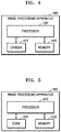
- FIG. 4 is a block diagram of an image processing apparatus 400, according to an exemplary embodiment.
- the image processing apparatus 400 may include a camera 410, a processor 430, and a memory 420.
- the image processing apparatus 400 may be any of an electronic apparatus (e.g., a computer, a mobile device, a display device, a wearable device, or a digital camera), a central processing unit (CPU), a graphic processing unit (GPU), or the like.
- an electronic apparatus e.g., a computer, a mobile device, a display device, a wearable device, or a digital camera
- CPU central processing unit
- GPU graphic processing unit
- the camera 410 may capture an image and acquire a color image and a depth image from the captured image.
- the color image and the depth image are acquired in units of frames.
- the color image may be a composite image that includes a red image, a green image, and a blue image.
- Each of the red image, the green image, and the blue image is a single frame.
- the depth image is acquired for each color.
- the camera 410 acquires a depth image for the red image, a depth image for the green image, and a depth image for the blue image.
- the depth image for each of the red, green, and blue images is also a single frame.
- the memory 420 stores the color image and the depth image.
- the memory 420 stores the frame generated by the processor 430.
- FIG. 5 is a block diagram of an image processing apparatus 500, according to another exemplary embodiment.
- the image processing apparatus 500 may be any of a mobile device, a display device, a wearable device, a CPU, a GPU, or the like.
- the image processing apparatus 500 includes a controller (also referred to herein as a "processor") 510, a core 520, and a memory 530.
- the memory 530 may include dynamic random-access memory (DRAM) or static random-access memory (SRAM).
- the controller 510 controls the core 520 and the memory 530.
- the controller 510 may determine data that is input to the core 520.
- the controller 510 may designate a calculation that is to be performed by the core 520.
- the controller 510 may control the core 520 to perform a 1D FFT operation on data in the row direction, and may also control the core 520 to perform a 1D FFT operation on data in the column direction.
- the controller 510 may store data generated during a Fourier transformation operation in the memory 530.
- the controller 510 controls the core 520 to perform a primary 2D FFT operation and a secondary 2D FFT operation on image data.
- the primary 2D FFT operation includes two 1D FFT operations
- the secondary 2D FFT operation includes two 1D FFT operations.
- the controller 510 may control the data that is input to the core 520, in order to perform a 2D FFT operation twice (i.e., to perform a primary 2D FFT operation and a secondary 2D FFT operation).
- the controller 510 controls a flow of data so that the core 520 performs a primary 2D FFT operation and then performs a secondary 2D FFT operation.
- the image processing apparatus 500 may perform a primary 2D FFT operation and a secondary 2D FFT operation (i.e., a total of four 1D FFT operations) by using the single core 520.
- the controller 510 may reset the core 520.
- Resetting the core 520 may refer to changing the amount of data that is processible by the core 520.
- Resetting the core 520 may also refer to determining whether an FFT processor included in the core 520 is to operate.
- the controller 510 may reset the core 520 so that the core 520 performs a 1K-POINT FFT operation or a 2K-POINT FFT operation.
- the controller 510 determines the amount of the data that is input to the core 520, based on the flow rate of the data, and determines whether FFT processors included in the core 520 are to operate, based on the determined amount of data.
- the core 520 may Fourier-transform data included in each line of the frame. For example, the core 520 may perform a 1D FFT operation on the frame in a row direction. A single row or a single column may be referred to as a single line. The core 520 performing a 1D FFT operation on the frame in the row direction indicates performing a 1D FFT operation on pixel values included in the row of the frame.
- the core 520 may output the data to the memory 530. Every time a result value obtained from performing a 1D FFT operation is generated, the core 520 may output the result value to the memory 530.
- the core 520 may include a plurality of 1D FFT processors.
- the 1D FFT processors may perform a respective 1D FFT operation on each line of the frame.
- the memory 530 may store and output the data.
- the memory 530 may include SDRAM or DRAM.
- FIG. 6 is a block diagram for explaining a flow of processing data, according to an exemplary embodiment.
- An input interface 610 receives image data.
- the image data may be transmitted to a memory 620 or a core 640 via a bus.
- the memory 620 may store and output data.
- the memory 620 may include SDRAM or DRAM.
- An output interface 630 outputs image data.
- the output interface 630 may be implemented as a display.
- the core 640 may be reset based on the amount of the image data in order to perform an FFT operation on the image data.
- the controller 510 controls a flow of the image data that is processed by an image processing apparatus 600, and resets the core 640 based on the amount of the image data that is input to the core 640.
- the image processing apparatus 600 may further include a plurality of operators.
- the plurality of operators may perform a focus term operation 650, a depth summation operation 660, a prism phase operation 670, a left-right (L/R) summation operation 680, and an encoding operation 690.
- FIG. 7 is a block diagram of a core 520, according to an exemplary embodiment.
- the core 520 may perform an FFT operation on image data of two amounts.
- the amount of the image data may vary based on the size of a panel. For example, when the size of the panel is 1K X 2K, the amount of the image data may be 1K X 2K. In this case, the core 520 needs to perform a 1K FFT operation and a 2K FFT operation. When the size of a replacement panel is 2K X 4K, the core 520 performs a 2K FFT operation and a 4K FFT operation.
- the core 520 In the core 520, according to a mode signal of the controller 510, only a basic module 521 may operate, or both a first additional module 522 and the basic module 521 may operate. Accordingly, the core 520 performs an FFT operation on image data of a first amount when only the basic module 521 operates, and performs an FFT operation on image data of a second amount when both the first additional module 522 and the basic module 521 operate.
- the core 520 includes the first additional module 522 and the basic module 521.
- the basic module 521 includes a plurality of FFT processors.
- one FFT processor may be a 2-POINT FFT processor.
- the first additional module 522 includes a single 2-POINT FFT processor. Whether the first additional module 522 is to operate may be determined under the control of the controller 510. Accordingly, when the first additional module 522 operates, the image data input to the first additional module 522 is transformed and then output to the basic module 521. Conversely, when the first additional module 522 does not operate, the image data input to the first additional module 522 is output to the basic module 521 without being transformed.
- FIG. 8 is a block diagram of a core 520, according to an exemplary embodiment.
- the core 520 may perform an FFT operation on image data of three amounts. Only the basic module 521 may operate, the first additional module 522 and the basic module 521 may operate, or a second additional module 523, the first additional module 522, and the basic module 521 may operate.
- the core 520 performs an FFT operation on image data of a first amount when only the basic module 521 operates; performs an FFT operation on image data of a second amount when the first additional module 522 and the basic module 521 operate; and performs an FFT operation on image data of a third amount when the second additional module 523, the first additional module 522, and the basic module 521 operate.
- the core 520 may include three or more additional modules, and may perform an FFT operation on image data of four or more amounts.
- FIG. 9 is a block diagram of a core 800, according to an exemplary embodiment.
- the core 800 is an example of a 2K-FFT module.
- the core 800 may control an additional module 820 to perform a 1K-FFT operation or a 2K-FFT operation.
- a 1K-FFT module 810 includes a plurality of 2-POINT processors or a plurality of 4-POINT FFT processors.
- the 1K-FFT module 810 may include ten 4-POINT FFT processors.
- Image data is input to the additional module 820.
- the image data is input to a ButterFly (BF) unit (also referred to herein as a ButterFly (BF) component) 824 and a multiplexer (MUX) 821 included in the additional module 820.
- BF ButterFly
- MUX multiplexer
- a mode signal is input to the MUX 821.
- a signal that is output by the MUX 821 varies based on the mode signal. For example, when the mode signal is one (1), the MUX 821 outputs the input image data to the additional module 820. When the mode signal is zero (0), the MUX 821 outputs image data obtained from a transformation operation performed by the additional module 820. In particular, when the mode signal is 0, the MUX 821 outputs data received from a complex multiplier 822.
- a twiddle factor (TF) read-only memory (ROM) 823 outputs a TF value.
- the TF ROM 823 may include any of a shift register, a cache, a memory, or the like.
- the BF unit 824 performs an FFT operation or an inverse FFT (IFFT) operation on the received image data.
- the BF unit 824 is controlled by a specific bit of an up-counter and constructs a single data path by using a Simple Dual-Port Block RAM (SDP-BRAM)-based delay feedback logic.
- SDP-BRAM Simple Dual-Port Block RAM
- the complex multiplier 822 performs a complex multiplication operation on the TF value output by the TF ROM 823 and data output by the BF unit 824.
- Whether the additional module 820 is to operate is determined based on the mode signal. According to whether the additional module 820 operates, a determination is made as to whether the core 800 is to operate as a 2K-FFT module or as a 1K-FFT module.
- FIG. 10 is a block diagram of the core 800 of FIG. 9 .
- FIG. 10 illustrates the core 800 of FIG. 9 in greater detail.
- the 1K-FFT module 810 includes five 4-POINT FFT processors.
- Each 4-POINT FFT processor includes two BF units, two TR ROMs, and one complex multiplier.
- Each BF unit may be a BF2I component or a BF2II component.
- a clock signal is applied to each BF unit.
- the additional module 820 includes the same components as those described above with reference to FIG. 9 .
- the additional module 820 may be connected to a front end of the 1K-FFT module 810 and configured to determine the image data that is input to the 1K-FFT module 810.
- the additional module 820 may include the FFT processors included in the 1K-FFT MODULE 810 and a MUX, and may output image data and/or transformed image data.
- FIG. 11 is a block diagram of a core 1000, according to an exemplary embodiment.
- the core 1000 is a detailed illustration of the core 520 of FIG. 8 .
- the core 1000 may process image data of three amounts. For example, the core 1000 may perform a 1K-POINT FFT operation, a 2K-POINT FFT operation, or a 4K-POINT FFT operation, wherein 1K, 2K, and 4K indicate amounts of image data.
- the core 1000 includes two additional modules, whether the additional modules are to operate is determined based on respective amounts of data.
- a 1 is input as a first mode signal to a MUX of a 2K-FFT module 800.
- a 0 is input as the first mode signal to the MUX of the 2K-FFT module 800
- a 1 is input as a second mode signal to a MUX of an additional module 900.
- a 0 is input as each of the first and second mode signals to the MUXes of the 2K-FFT module 800 and the additional module 900.
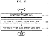
- FIG. 12 is a flowchart of an image processing method, according to an exemplary embodiment.
- an image processing apparatus determines the amount of image data.
- the amount of the image data may vary based on the size of a panel.
- the amount of the image data includes the sizes of rows and columns of the image data.
- the image processing apparatus sets a core based on the amount of the image data.
- the image processing apparatus sets the core based on the sizes of columns when performing an FFT operation on the image data in the row direction, and sets the core based on the sizes of rows when performing an FFT operation on the image data in the row direction.
- rows X columns of the image data is equivalent to 1K X 2K
- the image processing apparatus needs to perform a 2K-POINT FFT operation in order to perform a FFT operation in the row direction (because the number of rows is equal to 1K, whereas one row includes data of 2K-POINT).
- the image processing apparatus determines whether an additional module included in the core is to operate, and outputs a control signal (or mode signal) to the additional module based on the determination.
- a controller of the image processing apparatus may output a 0 or a 1 to a MUX included in the additional module and thus may determine output data of the MUX. For example, when a 1 is input to the MUX, the image data input to the additional module is output by the MUX. When a 0 is input to the MUX, the image data obtained from transformation performed by the additional module is output by the MUX.
- the core of the image processing apparatus may include a basic module, a first additional module, and a second additional module.
- the image processing apparatus outputs the control signal to a MUX of the first additional module and a MUX of the second additional module based on the amount of the image data.
- the core of the image processing apparatus performs a 1D FFT operation on the image data.
- the image processing apparatus may perform an FFT operation on image data even when the amount of the image data is changed by controlling an operation of the additional module.
- the image processing apparatus may process various amounts of image data by using the additional module connected to the basic module.
- the apparatuses described herein may comprise a processor, a memory configured for storing program data and executing a program that relates to the stored program data, a permanent storage unit such as a disk drive, a communications port configured for handling communications with external devices, and user interface devices, including a touch panel, keys, buttons, etc.
- a processor a memory configured for storing program data and executing a program that relates to the stored program data
- a permanent storage unit such as a disk drive
- a communications port configured for handling communications with external devices
- user interface devices including a touch panel, keys, buttons, etc.
- non-transitory computer-readable recording medium examples include magnetic storage media (e.g., read-only memory (ROM), random-access memory (RAM), floppy disks, hard disks, etc.), and optical recording media (e.g., compact disc - ROMs (CD-ROMs), or Digital Versatile Discs (DVDs)).
- the computer readable recording medium can also be distributed over network coupled computer systems so that the computer readable code is stored and executed in a distributive manner. This media can be read by the computer, stored in the memory, and executed by the processor.
- Exemplary embodiments may be described in terms of functional block components and various processing steps. Such functional blocks may be realized by any number of hardware and/or software components configured to perform the specified functions. For example, exemplary embodiments may employ various integrated circuit (IC) components, e.g., memory elements, processing elements, logic elements, look-up tables, and the like, which may carry out a variety of functions under the control of one or more microprocessors or other control devices. Similarly, where the elements are implemented by using software programming or software elements, the exemplary embodiments described herein may be implemented with any programming or scripting language such as C, C++, Java, assembler language, or the like, with the various algorithms being implemented with any combination of data structures, objects, processes, routines or other programming elements.
- IC integrated circuit
Landscapes
- Physics & Mathematics (AREA)
- Engineering & Computer Science (AREA)
- General Physics & Mathematics (AREA)
- Mathematical Physics (AREA)
- Theoretical Computer Science (AREA)
- Health & Medical Sciences (AREA)
- Data Mining & Analysis (AREA)
- Pure & Applied Mathematics (AREA)
- Mathematical Optimization (AREA)
- Mathematical Analysis (AREA)
- Computational Mathematics (AREA)
- Multimedia (AREA)
- Life Sciences & Earth Sciences (AREA)
- Medical Informatics (AREA)
- Discrete Mathematics (AREA)
- Nuclear Medicine, Radiotherapy & Molecular Imaging (AREA)
- Radiology & Medical Imaging (AREA)
- Computer Vision & Pattern Recognition (AREA)
- General Health & Medical Sciences (AREA)
- Optics & Photonics (AREA)
- General Engineering & Computer Science (AREA)
- Software Systems (AREA)
- Databases & Information Systems (AREA)
- Algebra (AREA)
- Molecular Biology (AREA)
- High Energy & Nuclear Physics (AREA)
- Biomedical Technology (AREA)
- Heart & Thoracic Surgery (AREA)
- Surgery (AREA)
- Veterinary Medicine (AREA)
- Public Health (AREA)
- Pathology (AREA)
- Animal Behavior & Ethology (AREA)
- Biophysics (AREA)
- Chemical & Material Sciences (AREA)
- Analytical Chemistry (AREA)
- Quality & Reliability (AREA)
- Signal Processing (AREA)
- Image Processing (AREA)
Abstract
Description
- Exemplary embodiments relate to a method and apparatus for processing an image.
- In the field of three-dimensional (3D) image technology, research has been actively conducted to develop apparatuses for realizing a high-definition hologram in real time by using a complex spatial light modulator (SLM) capable of simultaneously controlling the amplitude and phase of light.
- To reproduce a hologram moving picture, a computer-generated hologram (CGH) has been used. Image processing apparatuses perform a very large number of calculations to calculate a hologram value for each location in a hologram plane. In this aspect, in order to express a point in space, image processing apparatuses need to perform a Fourier transform operation one time. To express an image of a space, image processing apparatuses need to perform as many Fourier transform operations as the number of corresponding pixels of the image.
- Image processing apparatuses, such as televisions (TVs) and mobile devices, can process image data in order to reproduce a hologram image. In this case, the image processing apparatuses can perform Fourier transformation operations on the image data and reproduce an image by using the transformed data.
- When the image processing apparatuses perform Fourier transformation operations, a large number of calculations are performed, which is time consuming. In particular, portable devices such as mobile devices are limited with respect to both size and available power. Thus, there is a demand for methods of reducing the number of calculations and the calculation time when image processing apparatuses perform Fourier transformation operations.
- Provided are methods and apparatuses for performing Fourier transformation operations on image data.
- Additional aspects will be set forth in part in the description which follows and, in part, will be apparent from the description, or may be learned by practice of the presented exemplary embodiments.
- According to an aspect of an exemplary embodiment, an image processing apparatus for performing a fast Fourier transformation (FFT) operation on image data includes a core configured to perform an FFT operation on the image data; a memory configured to store data that is output by the core; and a controller configured to control the core to perform the FFT operation on the image data, wherein the core is resettable based on an amount of the image data.
- According to an aspect of another exemplary embodiment, an image processing method for performing a fast Fourier transformation (FFT) operation on image data includes determining an amount of the image data; setting a core based on the determined amount of image data; and controlling the core to perform a 1D FFT operation on the image data.
- These and/or other aspects will become apparent and more readily appreciated from the following description of exemplary embodiments, taken in conjunction with the accompanying drawings in which:
-
FIG. 1 is a schematic view illustrating a process of processing image data, according to an exemplary embodiment; -
FIG. 2 illustrates a process of transforming data, according to an exemplary embodiment; -
FIG. 3 illustrates a process of transforming data, according to another exemplary embodiment; -
FIG. 4 is a block diagram of an image processing apparatus, according to an exemplary embodiment; -
FIG. 5 is a block diagram of an image processing apparatus, according to another exemplary embodiment; -
FIG. 6 is a block diagram for explaining a flow of processing data, according to an exemplary embodiment; -
FIG. 7 is a block diagram of a core, according to an exemplary embodiment; -
FIG. 8 is a block diagram of a core, according to an exemplary embodiment; -
FIG. 9 is a block diagram of a core, according to an exemplary embodiment; -
FIG. 10 is a block diagram of a core, according to an exemplary embodiment; -
FIG. 11 is a block diagram of a core, according to an exemplary embodiment; and -
FIG. 12 is a flowchart of an image processing method, according to an exemplary embodiment. - Exemplary embodiments now will be described more fully hereinafter with reference to the accompanying drawings.
-
FIG. 1 is a schematic view illustrating a process of processing image data, according to an exemplary embodiment. Referring toFIG. 1 , an image processing apparatus may receive image data and output an image on which image processing has been performed. - In
operation 110, the image processing apparatus receives image data. For example, in computer-generated holography (CGH), when a layer-based algorithm is applied to image data, the image data may include color data (or a color image), depth data (or a depth image), or the like. The color data may include data that represents a plurality of colors for each plane of a plurality of planes. For example, the color data may include a red image, a blue image, and a green image. The layer-based algorithm is used to process data of each of the plurality of planes into which a reproduction area of a hologram is split based on depths. The image processing apparatus may generate a hologram image by performing a Fourier transform operation or an inverse Fourier transform operation on the data of each of the planes. - In
operation 120, the image processing apparatus performs an image quality correction operation and a field calculation operation. The image processing apparatus may correct the image data in order to improve an image quality. - In
operation 130, the image processing apparatus performs a Fourier transform operation or a fast Fourier transform (FFT) operation. For example, the image processing apparatus may perform a Fourier transform operation on a two-dimensional (2D) matrix type of image data. The image processing apparatus may perform a one-dimensional (1D) Fourier transform operation twice to accomplish a 2D Fourier transform. The image processing apparatus may perform a first 1D Fourier transform operation on the image data in a row direction and perform a second 1D Fourier transform operation on a result of the first 1D Fourier transform operation in a column direction. The image processing apparatus generates a hologram image via the Fourier transform operation. - The image processing apparatus may include a plurality of cores. The plurality of cores may be configured to perform a Fourier transform operation on the image data in parallel. For example, the image processing apparatus may allocate the image data of each plane to a respective one from among the plurality of cores, and each of the plurality of cores may perform a Fourier transform operation on the allocated image data. A process in which the image processing apparatus performs a Fourier transform operation on the image data according to exemplary embodiments will be described below in detail with reference to
FIGS. 2 ,3 ,4, 5 , and6 . - In
operation 140, the image processing apparatus performs a pixel encoding operation. The image processing apparatus generates data that is to be input to a screen, via the pixel encoding operation. - In
operation 150, the image processing apparatus outputs an image to an image display. -
FIG. 2 illustrates a process of transforming data, according to an exemplary embodiment. Referring toFIG. 2 , the image processing apparatus or a Fourier transform apparatus generatesfinal data 230 by performing a 1D FFT operation twice on image data 210 (i.e., a primary 2D FFT operation). For example, the image processing apparatus performs a 1D FFT operation once on theimage data 210 in the column direction to generateintermediate data 220, and then performs a 1D FFT operation once on theintermediate data 220 in the row direction to generate thefinal data 230. A secondary 2D FFT operation may also be achieved by performing a 1D FFT operation twice. The primary 2D FFT operation is an FFT operation from the pupil of a user to the retina of the user, and the secondary 2D FFT operation may be an FFT operation from a panel to the pupil. - The order of execution, in terms of column and row directions, of 1D FFT operations for the primary 2D FFT operation may be opposite to that of execution of 1D FFT operations for the secondary 2D FFT operation. For example, if 1D FFT operations are performed in the column direction and then in the row direction when a primary 2D FFT operation is performed, 1D FFT operations may be performed in the row direction and then in the column direction when a secondary 2D FFT operation is performed.
- In
FIG. 2 , for example, a case in which the image processing apparatus performs a 1D FFT operation first in the column direction is described. InFIG. 3 , for example, a case in which the image processing apparatus performs a 1D FFT operation first in the row direction is described. - Although only a case where a primary 2D FFT operation is performed is illustrated in
FIGS. 2 and3 , a secondary 2D FFT operation may also be performed in the same manner as the primary 2D FFT operation or by changing the order of a row and a column. - The image processing apparatus performs a 1D FFT operation on the
image data 210 in the column direction. Theintermediate data 220 is data obtained by performing a 1D FFT operation on theimage data 210 in the column direction. Arrows marked on theimage data 210 indicate directions in which the image processing apparatus performs a 1D FFT operation. Straight lines marked on theintermediate data 220 indicate directions in which theimage data 210 is transformed. - The image processing apparatus reads stored
intermediate data 220 from a memory and performs a 1D FFT operation on the readintermediate data 220 in the row direction. When reading out theintermediate data 220 from the memory, the image processing apparatus may read out theintermediate data 220 in the row direction and output the read-outintermediate data 220 to each 1D FFT processor. - The image processing apparatus generates the
final data 230 by performing a 1D FFT operation on theintermediate data 220 in the row direction. Thefinal data 230 is data obtained as theimage data 210 is 1D FFT-transformed respectively in the column direction and the row direction. -
FIG. 3 illustrates a process of transforming data, according to another exemplary embodiment. Referring toFIG. 3 , the image processing apparatus or a Fourier transform apparatus generatesfinal data 330 by performing a 1D FFT operation twice onimage data 310. For example, the image processing apparatus performs a 1D FFT operation once on theimage data 310 in the row direction to generateintermediate data 320 and then performs a 1D FFT operation once on theintermediate data 320 in the column direction to generate thefinal data 330. InFIGS. 2 and3 , the order of a column and a row is switched and the description presented inFIG. 2 may be identically applied to the description ofFIG. 3 . -
FIG. 4 is a block diagram of animage processing apparatus 400, according to an exemplary embodiment. Referring toFIG. 4 , theimage processing apparatus 400 may include acamera 410, aprocessor 430, and amemory 420. Theimage processing apparatus 400 may be any of an electronic apparatus (e.g., a computer, a mobile device, a display device, a wearable device, or a digital camera), a central processing unit (CPU), a graphic processing unit (GPU), or the like. - The
camera 410 may capture an image and acquire a color image and a depth image from the captured image. The color image and the depth image are acquired in units of frames. The color image may be a composite image that includes a red image, a green image, and a blue image. Each of the red image, the green image, and the blue image is a single frame. The depth image is acquired for each color. In this aspect, thecamera 410 acquires a depth image for the red image, a depth image for the green image, and a depth image for the blue image. The depth image for each of the red, green, and blue images is also a single frame. - The
memory 420 stores the color image and the depth image. Thememory 420 stores the frame generated by theprocessor 430. -
FIG. 5 is a block diagram of animage processing apparatus 500, according to another exemplary embodiment. Theimage processing apparatus 500 may be any of a mobile device, a display device, a wearable device, a CPU, a GPU, or the like. - The
image processing apparatus 500 includes a controller (also referred to herein as a "processor") 510, acore 520, and amemory 530. Thememory 530 may include dynamic random-access memory (DRAM) or static random-access memory (SRAM). - The
controller 510 controls thecore 520 and thememory 530. Thecontroller 510 may determine data that is input to thecore 520. Thecontroller 510 may designate a calculation that is to be performed by thecore 520. For example, thecontroller 510 may control thecore 520 to perform a 1D FFT operation on data in the row direction, and may also control thecore 520 to perform a 1D FFT operation on data in the column direction. Thecontroller 510 may store data generated during a Fourier transformation operation in thememory 530. - The
controller 510 controls thecore 520 to perform a primary 2D FFT operation and a secondary 2D FFT operation on image data. The primary 2D FFT operation includes two 1D FFT operations, and the secondary 2D FFT operation includes two 1D FFT operations. Thecontroller 510 may control the data that is input to thecore 520, in order to perform a 2D FFT operation twice (i.e., to perform a primary 2D FFT operation and a secondary 2D FFT operation). Thecontroller 510 controls a flow of data so that thecore 520 performs a primary 2D FFT operation and then performs a secondary 2D FFT operation. Accordingly, theimage processing apparatus 500 may perform a primary 2D FFT operation and a secondary 2D FFT operation (i.e., a total of four 1D FFT operations) by using thesingle core 520. - The
controller 510 may reset thecore 520. Resetting thecore 520 may refer to changing the amount of data that is processible by thecore 520. Resetting thecore 520 may also refer to determining whether an FFT processor included in thecore 520 is to operate. For example, thecontroller 510 may reset thecore 520 so that thecore 520 performs a 1K-POINT FFT operation or a 2K-POINT FFT operation. Thecontroller 510 determines the amount of the data that is input to thecore 520, based on the flow rate of the data, and determines whether FFT processors included in thecore 520 are to operate, based on the determined amount of data. - The
core 520 may Fourier-transform data included in each line of the frame. For example, thecore 520 may perform a 1D FFT operation on the frame in a row direction. A single row or a single column may be referred to as a single line. Thecore 520 performing a 1D FFT operation on the frame in the row direction indicates performing a 1D FFT operation on pixel values included in the row of the frame. - The
core 520 may output the data to thememory 530. Every time a result value obtained from performing a 1D FFT operation is generated, thecore 520 may output the result value to thememory 530. - The
core 520 may include a plurality of 1D FFT processors. The 1D FFT processors may perform a respective 1D FFT operation on each line of the frame. - The
memory 530 may store and output the data. Thememory 530 may include SDRAM or DRAM. -
FIG. 6 is a block diagram for explaining a flow of processing data, according to an exemplary embodiment. - An
input interface 610 receives image data. The image data may be transmitted to amemory 620 or acore 640 via a bus. - The
memory 620 may store and output data. Thememory 620 may include SDRAM or DRAM. - An
output interface 630 outputs image data. Theoutput interface 630 may be implemented as a display. - The
core 640 may be reset based on the amount of the image data in order to perform an FFT operation on the image data. - The
controller 510 controls a flow of the image data that is processed by animage processing apparatus 600, and resets thecore 640 based on the amount of the image data that is input to thecore 640. - Although not shown in
FIG. 6 , theimage processing apparatus 600 may further include a plurality of operators. The plurality of operators may perform afocus term operation 650, adepth summation operation 660, aprism phase operation 670, a left-right (L/R)summation operation 680, and anencoding operation 690. -
FIG. 7 is a block diagram of acore 520, according to an exemplary embodiment. Referring toFIG. 7 , thecore 520 may perform an FFT operation on image data of two amounts. - The amount of the image data may vary based on the size of a panel. For example, when the size of the panel is
1K X 2K, the amount of the image data may be1K X 2K. In this case, thecore 520 needs to perform a 1K FFT operation and a 2K FFT operation. When the size of a replacement panel is2K X 4K, thecore 520 performs a 2K FFT operation and a 4K FFT operation. - In the
core 520, according to a mode signal of thecontroller 510, only abasic module 521 may operate, or both a firstadditional module 522 and thebasic module 521 may operate. Accordingly, thecore 520 performs an FFT operation on image data of a first amount when only thebasic module 521 operates, and performs an FFT operation on image data of a second amount when both the firstadditional module 522 and thebasic module 521 operate. - The
core 520 includes the firstadditional module 522 and thebasic module 521. Thebasic module 521 includes a plurality of FFT processors. For example, one FFT processor may be a 2-POINT FFT processor. The firstadditional module 522 includes a single 2-POINT FFT processor. Whether the firstadditional module 522 is to operate may be determined under the control of thecontroller 510. Accordingly, when the firstadditional module 522 operates, the image data input to the firstadditional module 522 is transformed and then output to thebasic module 521. Conversely, when the firstadditional module 522 does not operate, the image data input to the firstadditional module 522 is output to thebasic module 521 without being transformed. -
FIG. 8 is a block diagram of acore 520, according to an exemplary embodiment. Referring toFIG. 8 , thecore 520 may perform an FFT operation on image data of three amounts. Only thebasic module 521 may operate, the firstadditional module 522 and thebasic module 521 may operate, or a secondadditional module 523, the firstadditional module 522, and thebasic module 521 may operate. Accordingly, thecore 520 performs an FFT operation on image data of a first amount when only thebasic module 521 operates; performs an FFT operation on image data of a second amount when the firstadditional module 522 and thebasic module 521 operate; and performs an FFT operation on image data of a third amount when the secondadditional module 523, the firstadditional module 522, and thebasic module 521 operate. - Although the
core 520 that includes two additional modules, namely, the first and secondadditional modules FIG. 8 , thecore 520 may include three or more additional modules, and may perform an FFT operation on image data of four or more amounts. -
FIG. 9 is a block diagram of acore 800, according to an exemplary embodiment. Referring toFIG. 9 , thecore 800 is an example of a 2K-FFT module. Thecore 800 may control anadditional module 820 to perform a 1K-FFT operation or a 2K-FFT operation. - For example, the
additional module 820 performs a function of a 2-POINT processor. A 1K-FFT module 810 includes a plurality of 2-POINT processors or a plurality of 4-POINT FFT processors. For example, the 1K-FFT module 810 may include ten 4-POINT FFT processors. - Image data is input to the
additional module 820. The image data is input to a ButterFly (BF) unit (also referred to herein as a ButterFly (BF) component) 824 and a multiplexer (MUX) 821 included in theadditional module 820. - A mode signal is input to the
MUX 821. A signal that is output by theMUX 821 varies based on the mode signal. For example, when the mode signal is one (1), theMUX 821 outputs the input image data to theadditional module 820. When the mode signal is zero (0), theMUX 821 outputs image data obtained from a transformation operation performed by theadditional module 820. In particular, when the mode signal is 0, theMUX 821 outputs data received from acomplex multiplier 822. - A twiddle factor (TF) read-only memory (ROM) 823 outputs a TF value. The
TF ROM 823 may include any of a shift register, a cache, a memory, or the like. - The
BF unit 824 performs an FFT operation or an inverse FFT (IFFT) operation on the received image data. TheBF unit 824 is controlled by a specific bit of an up-counter and constructs a single data path by using a Simple Dual-Port Block RAM (SDP-BRAM)-based delay feedback logic. - The
complex multiplier 822 performs a complex multiplication operation on the TF value output by theTF ROM 823 and data output by theBF unit 824. - Whether the
additional module 820 is to operate is determined based on the mode signal. According to whether theadditional module 820 operates, a determination is made as to whether thecore 800 is to operate as a 2K-FFT module or as a 1K-FFT module. -
FIG. 10 is a block diagram of thecore 800 ofFIG. 9 .FIG. 10 illustrates thecore 800 ofFIG. 9 in greater detail. - The 1K-
FFT module 810 includes five 4-POINT FFT processors. Each 4-POINT FFT processor includes two BF units, two TR ROMs, and one complex multiplier. Each BF unit may be a BF2I component or a BF2II component. A clock signal is applied to each BF unit. - The
additional module 820 includes the same components as those described above with reference toFIG. 9 . Theadditional module 820 may be connected to a front end of the 1K-FFT module 810 and configured to determine the image data that is input to the 1K-FFT module 810. Theadditional module 820 may include the FFT processors included in the 1K-FFT MODULE 810 and a MUX, and may output image data and/or transformed image data. -
FIG. 11 is a block diagram of acore 1000, according to an exemplary embodiment. Referring toFIG. 11 , thecore 1000 is a detailed illustration of thecore 520 ofFIG. 8 . - The
core 1000 may process image data of three amounts. For example, thecore 1000 may perform a 1K-POINT FFT operation, a 2K-POINT FFT operation, or a 4K-POINT FFT operation, wherein 1K, 2K, and 4K indicate amounts of image data. - Since the
core 1000 includes two additional modules, whether the additional modules are to operate is determined based on respective amounts of data. When the amount of data is equal to 1K, a 1 is input as a first mode signal to a MUX of a 2K-FFT module 800. When the amount of data is equal to 2K, a 0 is input as the first mode signal to the MUX of the 2K-FFT module 800, and a 1 is input as a second mode signal to a MUX of anadditional module 900. When the amount of data is equal to 4K, a 0 is input as each of the first and second mode signals to the MUXes of the 2K-FFT module 800 and theadditional module 900. -
FIG. 12 is a flowchart of an image processing method, according to an exemplary embodiment. - In
operation 1210, an image processing apparatus determines the amount of image data. The amount of the image data may vary based on the size of a panel. The amount of the image data includes the sizes of rows and columns of the image data. - In
operation 1220, the image processing apparatus sets a core based on the amount of the image data. The image processing apparatus sets the core based on the sizes of columns when performing an FFT operation on the image data in the row direction, and sets the core based on the sizes of rows when performing an FFT operation on the image data in the row direction. In particular, when rows X columns of the image data is equivalent to1K X 2K, the image processing apparatus needs to perform a 2K-POINT FFT operation in order to perform a FFT operation in the row direction (because the number of rows is equal to 1K, whereas one row includes data of 2K-POINT). - The image processing apparatus determines whether an additional module included in the core is to operate, and outputs a control signal (or mode signal) to the additional module based on the determination. A controller of the image processing apparatus may output a 0 or a 1 to a MUX included in the additional module and thus may determine output data of the MUX. For example, when a 1 is input to the MUX, the image data input to the additional module is output by the MUX. When a 0 is input to the MUX, the image data obtained from transformation performed by the additional module is output by the MUX.
- The core of the image processing apparatus may include a basic module, a first additional module, and a second additional module. The image processing apparatus outputs the control signal to a MUX of the first additional module and a MUX of the second additional module based on the amount of the image data.
- In
operation 1230, the core of the image processing apparatus performs a 1D FFT operation on the image data. - According to an exemplary embodiment, the image processing apparatus may perform an FFT operation on image data even when the amount of the image data is changed by controlling an operation of the additional module.
- According to an exemplary embodiment, the image processing apparatus may process various amounts of image data by using the additional module connected to the basic module.
- The apparatuses described herein may comprise a processor, a memory configured for storing program data and executing a program that relates to the stored program data, a permanent storage unit such as a disk drive, a communications port configured for handling communications with external devices, and user interface devices, including a touch panel, keys, buttons, etc. When software modules or algorithms are involved, these software modules may be stored as program instructions or computer readable codes executable on a processor on a transitory or non-transitory computer-readable recording medium. Examples of the non-transitory computer-readable recording medium include magnetic storage media (e.g., read-only memory (ROM), random-access memory (RAM), floppy disks, hard disks, etc.), and optical recording media (e.g., compact disc - ROMs (CD-ROMs), or Digital Versatile Discs (DVDs)). The computer readable recording medium can also be distributed over network coupled computer systems so that the computer readable code is stored and executed in a distributive manner. This media can be read by the computer, stored in the memory, and executed by the processor.
- Exemplary embodiments may be described in terms of functional block components and various processing steps. Such functional blocks may be realized by any number of hardware and/or software components configured to perform the specified functions. For example, exemplary embodiments may employ various integrated circuit (IC) components, e.g., memory elements, processing elements, logic elements, look-up tables, and the like, which may carry out a variety of functions under the control of one or more microprocessors or other control devices. Similarly, where the elements are implemented by using software programming or software elements, the exemplary embodiments described herein may be implemented with any programming or scripting language such as C, C++, Java, assembler language, or the like, with the various algorithms being implemented with any combination of data structures, objects, processes, routines or other programming elements. Functional aspects may be implemented by using algorithms that are executed on one or more processors. Furthermore, the exemplary embodiments described herein could employ any number of conventional techniques for electronics configuration, signal processing and/or control, data processing and the like. The words "mechanism," "element," "means," and "configuration" are used broadly and are not limited to mechanical or physical embodiments, but can include software routines in conjunction with processors, etc.
- The particular implementations shown and described herein are illustrative examples and are not intended to otherwise limit the scope of the present inventive concept in any way. For the sake of brevity, conventional electronics, control systems, software development and other functional aspects of the systems may not be described in detail. Furthermore, the connecting lines, or connectors shown in the various figures presented are intended to represent exemplary functional relationships and/or physical or logical couplings between the various elements. It should be noted that many alternative or additional functional relationships, physical connections or logical connections may be present in a practical apparatus.
- The use of the terms "a" and "an" and "the" and similar referents in the context of describing the exemplary embodiments (especially in the context of the following claims) are to be construed to cover both the singular and the plural. Furthermore, recitation of ranges of values herein are merely intended to serve as a shorthand method of referring individually to each separate value falling within the range, unless otherwise indicated herein, and each separate value is incorporated into the specification as if it were individually recited herein. Also, the steps of all methods described herein can be performed in any suitable order unless otherwise indicated herein or otherwise clearly contradicted by context. The exemplary embodiments are not limited to the described order of the steps. The use of any and all examples, or exemplary language (e.g., "such as") provided herein, is intended merely to better illuminate the present inventive concept and does not pose a limitation on the scope of the present inventive concept unless otherwise claimed. Numerous modifications and adaptations will be readily apparent to one of ordinary skill in the art without departing from the scope of the present disclosure.
Claims (15)
- An image processing apparatus, comprising:a core configured to perform a fast Fourier transformation, FFT, operation on image data;a memory configured to store data that is output by the core; anda controller configured to control the core to perform the FFT operation on the image data,wherein the core is resettable based on an amount of the image data.
- The image processing apparatus of claim 1, wherein
the core comprises a basic module and an additional module, and
the controller is further configured to output, to the core, a control signal that is usable for determining whether the additional module is to operate. - The image processing apparatus of claim 2, wherein
the basic module is a 1K FFT module,
when a 1K FFT operation is to be performed, the controller is further configured to control the additional module to stop operating so that the core performs the 1K FFT operation, and
when a 2K FFT operation is to be performed, the controller is further configured to control the additional module to operate so that the core performs the 2K FFT operation. - The image processing apparatus of claim 2 or 3, wherein the additional module is connected to the basic module, and data to be output by the additional module is input to the basic module.
- The image processing apparatus of any preceding claim, wherein
the core comprises a twiddle factor, TF, read-only memory, ROM, a butterfly (BF) component, a complex multiplier, and a multiplexer (MUX), and
the controller is further configured to output a control signal to the MUX that is usable for determining a value that is to be output by the MUX. - The image processing apparatus of any preceding claim, wherein the controller is further configured to reset the core based on at least one from among a size of a row of the image data and a size of a column of the image data.
- The image processing apparatus of any preceding claim, wherein the controller is further configured to reset the core based on an amount of data processed by the core.
- The image processing apparatus of any preceding claim, wherein
the core comprises a basic module, a first additional module, and a second additional module,
the first additional module is connected to an input end of the basic module, and the second additional module is connected to an input end of the first additional module,
each of the first additional module and the second additional module comprises a multiplexer, MUX, and
the controller is further configured to output a control signal to each of the MUX of the first additional module and the MUX of the second additional module based on an amount of the image data. - An image processing method for performing a fast Fourier transformation, FFT, operation on image data, the image processing method comprising:determining an amount of the image data;setting a core based on the determined amount; andcontrolling the core to perform a 1D FFT operation on the image data.
- The image processing method of claim 9, wherein the determining the amount of the image data comprises determining a size of a column of the image data and determining a size of a row of the image data.
- The image processing method of claim 9 or 10, wherein the setting the core comprises:when a 1D FFT operation in a row direction is to be performed on the image data, setting the core based on a size of a column of the image data; andwhen a 1D FFT operation in a column direction is to be performed on the image data, setting the core based on a size of a row of the image data.
- The image processing method of claim 9, 10 or 11, wherein the setting the core comprises:determining whether an additional module included in the core is to operate; andoutputting a control signal to the additional module, based on a result of the determining.
- The image processing method of claim 12, wherein the outputting the control signal comprises outputting one from among a zero and a one to a multiplexer (MUX) included in the additional module and determining output data of the MUX.
- The image processing method of any of claims 9 to 13, wherein
the core comprises a basic module, a first additional module, and a second additional module, and
the setting the core comprises outputting a control signal to each of a multiplexer, MUX, of the first additional module and a MUX of the second additional module based on the amount of the image data. - A computer program comprising computer program code means adapted to perform all of the steps of any of claims 9 to 14 when said program is run on a computer.
Applications Claiming Priority (1)
| Application Number | Priority Date | Filing Date | Title |
|---|---|---|---|
| KR1020160165175A KR102664387B1 (en) | 2016-12-06 | 2016-12-06 | Apparatus and Method of processing image |
Publications (2)
| Publication Number | Publication Date |
|---|---|
| EP3333719A1 true EP3333719A1 (en) | 2018-06-13 |
| EP3333719B1 EP3333719B1 (en) | 2025-01-08 |
Family
ID=60450507
Family Applications (1)
| Application Number | Title | Priority Date | Filing Date |
|---|---|---|---|
| EP17203099.1A Active EP3333719B1 (en) | 2016-12-06 | 2017-11-22 | Method and apparatus for processing an image |
Country Status (4)
| Country | Link |
|---|---|
| US (1) | US10545328B2 (en) |
| EP (1) | EP3333719B1 (en) |
| KR (1) | KR102664387B1 (en) |
| CN (1) | CN108154473A (en) |
Families Citing this family (1)
| Publication number | Priority date | Publication date | Assignee | Title |
|---|---|---|---|---|
| KR102732451B1 (en) * | 2019-04-01 | 2024-11-21 | 삼성전자주식회사 | Apparatus and method for processing hologram image data |
Citations (1)
| Publication number | Priority date | Publication date | Assignee | Title |
|---|---|---|---|---|
| US20090013021A1 (en) * | 2007-07-06 | 2009-01-08 | Mediatek Inc. | Variable length fft system and method |
Family Cites Families (28)
| Publication number | Priority date | Publication date | Assignee | Title |
|---|---|---|---|---|
| US5526506A (en) * | 1970-12-28 | 1996-06-11 | Hyatt; Gilbert P. | Computer system having an improved memory architecture |
| US5053983A (en) * | 1971-04-19 | 1991-10-01 | Hyatt Gilbert P | Filter system having an adaptive control for updating filter samples |
| US5974178A (en) | 1996-10-07 | 1999-10-26 | Advantest Corporation | Wavesource image visualization method using a partial division fast fourier transform |
| JP2008117044A (en) * | 2006-11-01 | 2008-05-22 | Oki Electric Ind Co Ltd | Two-dimensional fast fourier transform operation method and two-dimensional fast fourier transform operation device |
| US5859788A (en) * | 1997-08-15 | 1999-01-12 | The Aerospace Corporation | Modulated lapped transform method |
| US6333743B1 (en) * | 1997-10-23 | 2001-12-25 | Silicon Graphics, Inc. | Method and apparatus for providing image and graphics processing using a graphics rendering engine |
| US6940807B1 (en) * | 1999-10-26 | 2005-09-06 | Velocity Communication, Inc. | Method and apparatus for a X-DSL communication processor |
| US7236637B2 (en) * | 1999-11-24 | 2007-06-26 | Ge Medical Systems Information Technologies, Inc. | Method and apparatus for transmission and display of a compressed digitized image |
| JP2004206254A (en) | 2002-12-24 | 2004-07-22 | Mega Chips Corp | Fourier transformation device and its method, computer hologram generation device and its method and device for manufacturing diffraction optical element |
| CN100547580C (en) * | 2004-07-08 | 2009-10-07 | 阿苏克斯有限公司 | Method and apparatus for implementing variable size fast orthogonal transforms |
| US7577698B2 (en) * | 2004-12-28 | 2009-08-18 | Industrial Technology Research Institute | Fast fourier transform processor |
| CN101300572A (en) * | 2005-03-11 | 2008-11-05 | 高通股份有限公司 | Fast Fourier Transform rotation multiplication |
| GB2425860A (en) * | 2005-05-05 | 2006-11-08 | Advanced Risc Mach Ltd | Multi-dimensional fast fourier transform |
| GB0518912D0 (en) | 2005-09-16 | 2005-10-26 | Light Blue Optics Ltd | Methods and apparatus for displaying images using holograms |
| US8186379B2 (en) * | 2007-06-26 | 2012-05-29 | Advics Co., Ltd. | Electromagnetic valve and method for manufacturing the same |
| US9342486B2 (en) * | 2008-10-03 | 2016-05-17 | Microsoft Technology Licensing, Llc | Fast computation of general fourier transforms on graphics processing units |
| US8548257B2 (en) * | 2009-01-05 | 2013-10-01 | Apple Inc. | Distinguishing between faces and non-faces |
| JP5683213B2 (en) * | 2009-11-17 | 2015-03-11 | キヤノン株式会社 | Image forming apparatus and image forming method |
| US20120269239A1 (en) * | 2011-04-20 | 2012-10-25 | Mykhaylo Sabelkin | Method and Apparatus for Data Transmission Oriented on the Object, Communication Media, Agents, and State of Communication Systems |
| US8848465B2 (en) * | 2011-07-06 | 2014-09-30 | Samsung Electronics Co., Ltd. | Memory devices including selective RWW and RMW decoding |
| KR101366116B1 (en) | 2012-10-31 | 2014-02-24 | 전자부품연구원 | Fft parallel processing method, data processing method and hologram restoration apparatus |
| JP6101475B2 (en) * | 2012-12-06 | 2017-03-22 | 株式会社トプコン | Ophthalmic observation device |
| ITTO20130032A1 (en) * | 2013-01-15 | 2014-07-16 | St Microelectronics Srl | PROCEDURE AND EQUIPMENT FOR CALCULATING IMAGE PYRAMIDS AND ITS COMPUTER PRODUCT |
| US9081731B2 (en) * | 2013-01-31 | 2015-07-14 | Inview Technology Corporation | Efficient transforms and efficient row generation for Kronecker products of Hadamard matrices |
| KR20140125608A (en) | 2013-04-19 | 2014-10-29 | 엘지전자 주식회사 | Apparatus and method for displaying hologram |
| US9183648B2 (en) * | 2014-03-04 | 2015-11-10 | Ivan Bajic | Method and system for high-resolution transforms of frequency-space and image/audio/video-space data |
| KR102224718B1 (en) | 2014-08-06 | 2021-03-08 | 삼성전자주식회사 | Method and apparatus for generating hologram |
| KR102452945B1 (en) * | 2015-08-27 | 2022-10-11 | 삼성전자주식회사 | Apparatus and Method for performing Fourier transform |
-
2016
- 2016-12-06 KR KR1020160165175A patent/KR102664387B1/en active Active
-
2017
- 2017-10-04 US US15/724,459 patent/US10545328B2/en active Active
- 2017-11-22 EP EP17203099.1A patent/EP3333719B1/en active Active
- 2017-12-06 CN CN201711273986.XA patent/CN108154473A/en active Pending
Patent Citations (1)
| Publication number | Priority date | Publication date | Assignee | Title |
|---|---|---|---|---|
| US20090013021A1 (en) * | 2007-07-06 | 2009-01-08 | Mediatek Inc. | Variable length fft system and method |
Non-Patent Citations (1)
| Title |
|---|
| LIN Y-T ET AL: "Low-power variable-length fast Fourier transform processor", IEE PROCEEDINGS: COMPUTERS AND DIGITAL TECHNIQ, IEE, GB, vol. 152, no. 4, 8 July 2005 (2005-07-08), pages 499 - 506, XP006024793, ISSN: 1350-2387, DOI: 10.1049/IP-CDT:20041224 * |
Also Published As
| Publication number | Publication date |
|---|---|
| KR20180064823A (en) | 2018-06-15 |
| US20180157024A1 (en) | 2018-06-07 |
| CN108154473A (en) | 2018-06-12 |
| EP3333719B1 (en) | 2025-01-08 |
| KR102664387B1 (en) | 2024-05-08 |
| US10545328B2 (en) | 2020-01-28 |
Similar Documents
| Publication | Publication Date | Title |
|---|---|---|
| US10321159B2 (en) | Apparatus and method of performing fourier transform | |
| US11727659B2 (en) | Method and apparatus for processing three-dimensional (3D) image | |
| EP3629099B1 (en) | Method and apparatus for processing hologram image data | |
| US10275849B2 (en) | Image processing method and apparatus for performing two-dimensional fast Fourier transform with respect to image data | |
| US20160156902A1 (en) | Method and apparatus for generating three-dimensional image | |
| US10230933B2 (en) | Processing three-dimensional (3D) image through selectively processing stereoscopic images | |
| US10223763B2 (en) | Apparatus and method for performing fourier transform | |
| US20190155217A1 (en) | Method and apparatus for processing image | |
| US10545328B2 (en) | Method and apparatus for processing image | |
| KR20160014288A (en) | Method for rendering three dimensional image of circle type display | |
| US20160163093A1 (en) | Method and apparatus for generating image | |
| CN109873999B (en) | Image data processing method and device | |
| CN111800621A (en) | Method and apparatus for processing hologram image data |
Legal Events
| Date | Code | Title | Description |
|---|---|---|---|
| PUAI | Public reference made under article 153(3) epc to a published international application that has entered the european phase |
Free format text: ORIGINAL CODE: 0009012 |
|
| STAA | Information on the status of an ep patent application or granted ep patent |
Free format text: STATUS: THE APPLICATION HAS BEEN PUBLISHED |
|
| AK | Designated contracting states |
Kind code of ref document: A1 Designated state(s): AL AT BE BG CH CY CZ DE DK EE ES FI FR GB GR HR HU IE IS IT LI LT LU LV MC MK MT NL NO PL PT RO RS SE SI SK SM TR |
|
| AX | Request for extension of the european patent |
Extension state: BA ME |
|
| STAA | Information on the status of an ep patent application or granted ep patent |
Free format text: STATUS: REQUEST FOR EXAMINATION WAS MADE |
|
| 17P | Request for examination filed |
Effective date: 20181213 |
|
| RBV | Designated contracting states (corrected) |
Designated state(s): AL AT BE BG CH CY CZ DE DK EE ES FI FR GB GR HR HU IE IS IT LI LT LU LV MC MK MT NL NO PL PT RO RS SE SI SK SM TR |
|
| STAA | Information on the status of an ep patent application or granted ep patent |
Free format text: STATUS: EXAMINATION IS IN PROGRESS |
|
| 17Q | First examination report despatched |
Effective date: 20210514 |
|
| P01 | Opt-out of the competence of the unified patent court (upc) registered |
Effective date: 20230530 |
|
| GRAP | Despatch of communication of intention to grant a patent |
Free format text: ORIGINAL CODE: EPIDOSNIGR1 |
|
| STAA | Information on the status of an ep patent application or granted ep patent |
Free format text: STATUS: GRANT OF PATENT IS INTENDED |
|
| RIC1 | Information provided on ipc code assigned before grant |
Ipc: G03H 1/08 20060101ALI20240724BHEP Ipc: G06F 17/14 20060101AFI20240724BHEP |
|
| INTG | Intention to grant announced |
Effective date: 20240807 |
|
| RAP3 | Party data changed (applicant data changed or rights of an application transferred) |
Owner name: UNIVERSITY OF SEOUL INDUSTRYCOOPERATION FOUNDATION Owner name: SAMSUNG ELECTRONICS CO., LTD |
|
| RIN1 | Information on inventor provided before grant (corrected) |
Inventor name: KIM, KICHUL Inventor name: LEE, HONGSEOK Inventor name: KIM, YONGKYU Inventor name: KIM, HOJUNG |
|
| GRAS | Grant fee paid |
Free format text: ORIGINAL CODE: EPIDOSNIGR3 |
|
| GRAA | (expected) grant |
Free format text: ORIGINAL CODE: 0009210 |
|
| STAA | Information on the status of an ep patent application or granted ep patent |
Free format text: STATUS: THE PATENT HAS BEEN GRANTED |
|
| AK | Designated contracting states |
Kind code of ref document: B1 Designated state(s): AL AT BE BG CH CY CZ DE DK EE ES FI FR GB GR HR HU IE IS IT LI LT LU LV MC MK MT NL NO PL PT RO RS SE SI SK SM TR |
|
| REG | Reference to a national code |
Ref country code: GB Ref legal event code: FG4D |
|
| REG | Reference to a national code |
Ref country code: CH Ref legal event code: EP |
|
| REG | Reference to a national code |
Ref country code: DE Ref legal event code: R096 Ref document number: 602017087219 Country of ref document: DE |
|
| REG | Reference to a national code |
Ref country code: IE Ref legal event code: FG4D |
|
| REG | Reference to a national code |
Ref country code: LT Ref legal event code: MG9D |
|
| REG | Reference to a national code |
Ref country code: NL Ref legal event code: MP Effective date: 20250108 |
|
| REG | Reference to a national code |
Ref country code: AT Ref legal event code: MK05 Ref document number: 1758803 Country of ref document: AT Kind code of ref document: T Effective date: 20250108 |
|
| PG25 | Lapsed in a contracting state [announced via postgrant information from national office to epo] |
Ref country code: NL Free format text: LAPSE BECAUSE OF FAILURE TO SUBMIT A TRANSLATION OF THE DESCRIPTION OR TO PAY THE FEE WITHIN THE PRESCRIBED TIME-LIMIT Effective date: 20250108 |
|
| PG25 | Lapsed in a contracting state [announced via postgrant information from national office to epo] |
Ref country code: RS Free format text: LAPSE BECAUSE OF FAILURE TO SUBMIT A TRANSLATION OF THE DESCRIPTION OR TO PAY THE FEE WITHIN THE PRESCRIBED TIME-LIMIT Effective date: 20250408 |
|
| PG25 | Lapsed in a contracting state [announced via postgrant information from national office to epo] |
Ref country code: FI Free format text: LAPSE BECAUSE OF FAILURE TO SUBMIT A TRANSLATION OF THE DESCRIPTION OR TO PAY THE FEE WITHIN THE PRESCRIBED TIME-LIMIT Effective date: 20250108 |
|
| PG25 | Lapsed in a contracting state [announced via postgrant information from national office to epo] |
Ref country code: PL Free format text: LAPSE BECAUSE OF FAILURE TO SUBMIT A TRANSLATION OF THE DESCRIPTION OR TO PAY THE FEE WITHIN THE PRESCRIBED TIME-LIMIT Effective date: 20250108 |
|
| PG25 | Lapsed in a contracting state [announced via postgrant information from national office to epo] |
Ref country code: ES Free format text: LAPSE BECAUSE OF FAILURE TO SUBMIT A TRANSLATION OF THE DESCRIPTION OR TO PAY THE FEE WITHIN THE PRESCRIBED TIME-LIMIT Effective date: 20250108 |
|
| PG25 | Lapsed in a contracting state [announced via postgrant information from national office to epo] |
Ref country code: IS Free format text: LAPSE BECAUSE OF FAILURE TO SUBMIT A TRANSLATION OF THE DESCRIPTION OR TO PAY THE FEE WITHIN THE PRESCRIBED TIME-LIMIT Effective date: 20250508 Ref country code: NO Free format text: LAPSE BECAUSE OF FAILURE TO SUBMIT A TRANSLATION OF THE DESCRIPTION OR TO PAY THE FEE WITHIN THE PRESCRIBED TIME-LIMIT Effective date: 20250408 |
|
| PG25 | Lapsed in a contracting state [announced via postgrant information from national office to epo] |
Ref country code: HR Free format text: LAPSE BECAUSE OF FAILURE TO SUBMIT A TRANSLATION OF THE DESCRIPTION OR TO PAY THE FEE WITHIN THE PRESCRIBED TIME-LIMIT Effective date: 20250108 |
|
| PG25 | Lapsed in a contracting state [announced via postgrant information from national office to epo] |
Ref country code: PT Free format text: LAPSE BECAUSE OF FAILURE TO SUBMIT A TRANSLATION OF THE DESCRIPTION OR TO PAY THE FEE WITHIN THE PRESCRIBED TIME-LIMIT Effective date: 20250508 Ref country code: LV Free format text: LAPSE BECAUSE OF FAILURE TO SUBMIT A TRANSLATION OF THE DESCRIPTION OR TO PAY THE FEE WITHIN THE PRESCRIBED TIME-LIMIT Effective date: 20250108 |
|
| PG25 | Lapsed in a contracting state [announced via postgrant information from national office to epo] |
Ref country code: BG Free format text: LAPSE BECAUSE OF FAILURE TO SUBMIT A TRANSLATION OF THE DESCRIPTION OR TO PAY THE FEE WITHIN THE PRESCRIBED TIME-LIMIT Effective date: 20250108 Ref country code: GR Free format text: LAPSE BECAUSE OF FAILURE TO SUBMIT A TRANSLATION OF THE DESCRIPTION OR TO PAY THE FEE WITHIN THE PRESCRIBED TIME-LIMIT Effective date: 20250409 |
|
| PG25 | Lapsed in a contracting state [announced via postgrant information from national office to epo] |
Ref country code: AT Free format text: LAPSE BECAUSE OF FAILURE TO SUBMIT A TRANSLATION OF THE DESCRIPTION OR TO PAY THE FEE WITHIN THE PRESCRIBED TIME-LIMIT Effective date: 20250108 |
|
| PG25 | Lapsed in a contracting state [announced via postgrant information from national office to epo] |
Ref country code: SE Free format text: LAPSE BECAUSE OF FAILURE TO SUBMIT A TRANSLATION OF THE DESCRIPTION OR TO PAY THE FEE WITHIN THE PRESCRIBED TIME-LIMIT Effective date: 20250108 |
|
| PG25 | Lapsed in a contracting state [announced via postgrant information from national office to epo] |
Ref country code: SM Free format text: LAPSE BECAUSE OF FAILURE TO SUBMIT A TRANSLATION OF THE DESCRIPTION OR TO PAY THE FEE WITHIN THE PRESCRIBED TIME-LIMIT Effective date: 20250108 |
|
| REG | Reference to a national code |
Ref country code: DE Ref legal event code: R097 Ref document number: 602017087219 Country of ref document: DE |
|
| PG25 | Lapsed in a contracting state [announced via postgrant information from national office to epo] |
Ref country code: DK Free format text: LAPSE BECAUSE OF FAILURE TO SUBMIT A TRANSLATION OF THE DESCRIPTION OR TO PAY THE FEE WITHIN THE PRESCRIBED TIME-LIMIT Effective date: 20250108 |
|
| PG25 | Lapsed in a contracting state [announced via postgrant information from national office to epo] |
Ref country code: EE Free format text: LAPSE BECAUSE OF FAILURE TO SUBMIT A TRANSLATION OF THE DESCRIPTION OR TO PAY THE FEE WITHIN THE PRESCRIBED TIME-LIMIT Effective date: 20250108 Ref country code: CZ Free format text: LAPSE BECAUSE OF FAILURE TO SUBMIT A TRANSLATION OF THE DESCRIPTION OR TO PAY THE FEE WITHIN THE PRESCRIBED TIME-LIMIT Effective date: 20250108 |
|
| PG25 | Lapsed in a contracting state [announced via postgrant information from national office to epo] |
Ref country code: RO Free format text: LAPSE BECAUSE OF FAILURE TO SUBMIT A TRANSLATION OF THE DESCRIPTION OR TO PAY THE FEE WITHIN THE PRESCRIBED TIME-LIMIT Effective date: 20250108 |
|
| PG25 | Lapsed in a contracting state [announced via postgrant information from national office to epo] |
Ref country code: SK Free format text: LAPSE BECAUSE OF FAILURE TO SUBMIT A TRANSLATION OF THE DESCRIPTION OR TO PAY THE FEE WITHIN THE PRESCRIBED TIME-LIMIT Effective date: 20250108 |
|
| PLBE | No opposition filed within time limit |
Free format text: ORIGINAL CODE: 0009261 |
|
| STAA | Information on the status of an ep patent application or granted ep patent |
Free format text: STATUS: NO OPPOSITION FILED WITHIN TIME LIMIT |
|
| REG | Reference to a national code |
Ref country code: CH Ref legal event code: L10 Free format text: ST27 STATUS EVENT CODE: U-0-0-L10-L00 (AS PROVIDED BY THE NATIONAL OFFICE) Effective date: 20251119 |
|
| 26N | No opposition filed |
Effective date: 20251009 |
|
| PGFP | Annual fee paid to national office [announced via postgrant information from national office to epo] |
Ref country code: DE Payment date: 20251022 Year of fee payment: 9 |
|
| PGFP | Annual fee paid to national office [announced via postgrant information from national office to epo] |
Ref country code: GB Payment date: 20251016 Year of fee payment: 9 |
|
| PGFP | Annual fee paid to national office [announced via postgrant information from national office to epo] |
Ref country code: FR Payment date: 20251023 Year of fee payment: 9 |
|
| PG25 | Lapsed in a contracting state [announced via postgrant information from national office to epo] |
Ref country code: IT Free format text: LAPSE BECAUSE OF FAILURE TO SUBMIT A TRANSLATION OF THE DESCRIPTION OR TO PAY THE FEE WITHIN THE PRESCRIBED TIME-LIMIT Effective date: 20250108 |
|
| REG | Reference to a national code |
Ref country code: CH Ref legal event code: H13 Free format text: ST27 STATUS EVENT CODE: U-0-0-H10-H13 (AS PROVIDED BY THE NATIONAL OFFICE) Effective date: 20260623 |
|
| PG25 | Lapsed in a contracting state [announced via postgrant information from national office to epo] |
Ref country code: LT Free format text: LAPSE BECAUSE OF FAILURE TO SUBMIT A TRANSLATION OF THE DESCRIPTION OR TO PAY THE FEE WITHIN THE PRESCRIBED TIME-LIMIT Effective date: 20250108 |
|
| PG25 | Lapsed in a contracting state [announced via postgrant information from national office to epo] |
Ref country code: MC Free format text: LAPSE BECAUSE OF FAILURE TO SUBMIT A TRANSLATION OF THE DESCRIPTION OR TO PAY THE FEE WITHIN THE PRESCRIBED TIME-LIMIT Effective date: 20250108 |
|
| PG25 | Lapsed in a contracting state [announced via postgrant information from national office to epo] |
Ref country code: LU Free format text: LAPSE BECAUSE OF NON-PAYMENT OF DUE FEES Effective date: 20251122 Ref country code: CH Free format text: LAPSE BECAUSE OF NON-PAYMENT OF DUE FEES Effective date: 20251130 |