EP3333628A1 - Camera device including aperture and electronic device including the same - Google Patents
Camera device including aperture and electronic device including the same Download PDFInfo
- Publication number
- EP3333628A1 EP3333628A1 EP17205978.4A EP17205978A EP3333628A1 EP 3333628 A1 EP3333628 A1 EP 3333628A1 EP 17205978 A EP17205978 A EP 17205978A EP 3333628 A1 EP3333628 A1 EP 3333628A1
- Authority
- EP
- European Patent Office
- Prior art keywords
- aperture
- lever
- hole
- movable carrier
- hole area
- Prior art date
- Legal status (The legal status is an assumption and is not a legal conclusion. Google has not performed a legal analysis and makes no representation as to the accuracy of the status listed.)
- Granted
Links
Images















Classifications
-
- G—PHYSICS
- G03—PHOTOGRAPHY; CINEMATOGRAPHY; ANALOGOUS TECHNIQUES USING WAVES OTHER THAN OPTICAL WAVES; ELECTROGRAPHY; HOLOGRAPHY
- G03B—APPARATUS OR ARRANGEMENTS FOR TAKING PHOTOGRAPHS OR FOR PROJECTING OR VIEWING THEM; APPARATUS OR ARRANGEMENTS EMPLOYING ANALOGOUS TECHNIQUES USING WAVES OTHER THAN OPTICAL WAVES; ACCESSORIES THEREFOR
- G03B9/00—Exposure-making shutters; Diaphragms
- G03B9/02—Diaphragms
-
- G—PHYSICS
- G03—PHOTOGRAPHY; CINEMATOGRAPHY; ANALOGOUS TECHNIQUES USING WAVES OTHER THAN OPTICAL WAVES; ELECTROGRAPHY; HOLOGRAPHY
- G03B—APPARATUS OR ARRANGEMENTS FOR TAKING PHOTOGRAPHS OR FOR PROJECTING OR VIEWING THEM; APPARATUS OR ARRANGEMENTS EMPLOYING ANALOGOUS TECHNIQUES USING WAVES OTHER THAN OPTICAL WAVES; ACCESSORIES THEREFOR
- G03B30/00—Camera modules comprising integrated lens units and imaging units, specially adapted for being embedded in other devices, e.g. mobile phones or vehicles
-
- G—PHYSICS
- G02—OPTICS
- G02B—OPTICAL ELEMENTS, SYSTEMS OR APPARATUS
- G02B7/00—Mountings, adjusting means, or light-tight connections, for optical elements
- G02B7/02—Mountings, adjusting means, or light-tight connections, for optical elements for lenses
- G02B7/04—Mountings, adjusting means, or light-tight connections, for optical elements for lenses with mechanism for focusing or varying magnification
- G02B7/09—Mountings, adjusting means, or light-tight connections, for optical elements for lenses with mechanism for focusing or varying magnification adapted for automatic focusing or varying magnification
-
- G—PHYSICS
- G02—OPTICS
- G02B—OPTICAL ELEMENTS, SYSTEMS OR APPARATUS
- G02B13/00—Optical objectives specially designed for the purposes specified below
- G02B13/001—Miniaturised objectives for electronic devices, e.g. portable telephones, webcams, PDAs, small digital cameras
-
- G—PHYSICS
- G02—OPTICS
- G02B—OPTICAL ELEMENTS, SYSTEMS OR APPARATUS
- G02B7/00—Mountings, adjusting means, or light-tight connections, for optical elements
- G02B7/02—Mountings, adjusting means, or light-tight connections, for optical elements for lenses
-
- G—PHYSICS
- G03—PHOTOGRAPHY; CINEMATOGRAPHY; ANALOGOUS TECHNIQUES USING WAVES OTHER THAN OPTICAL WAVES; ELECTROGRAPHY; HOLOGRAPHY
- G03B—APPARATUS OR ARRANGEMENTS FOR TAKING PHOTOGRAPHS OR FOR PROJECTING OR VIEWING THEM; APPARATUS OR ARRANGEMENTS EMPLOYING ANALOGOUS TECHNIQUES USING WAVES OTHER THAN OPTICAL WAVES; ACCESSORIES THEREFOR
- G03B17/00—Details of cameras or camera bodies; Accessories therefor
- G03B17/02—Bodies
- G03B17/12—Bodies with means for supporting objectives, supplementary lenses, filters, masks, or turrets
-
- G—PHYSICS
- G03—PHOTOGRAPHY; CINEMATOGRAPHY; ANALOGOUS TECHNIQUES USING WAVES OTHER THAN OPTICAL WAVES; ELECTROGRAPHY; HOLOGRAPHY
- G03B—APPARATUS OR ARRANGEMENTS FOR TAKING PHOTOGRAPHS OR FOR PROJECTING OR VIEWING THEM; APPARATUS OR ARRANGEMENTS EMPLOYING ANALOGOUS TECHNIQUES USING WAVES OTHER THAN OPTICAL WAVES; ACCESSORIES THEREFOR
- G03B5/00—Adjustment of optical system relative to image or object surface other than for focusing
- G03B5/02—Lateral adjustment of lens
-
- G—PHYSICS
- G03—PHOTOGRAPHY; CINEMATOGRAPHY; ANALOGOUS TECHNIQUES USING WAVES OTHER THAN OPTICAL WAVES; ELECTROGRAPHY; HOLOGRAPHY
- G03B—APPARATUS OR ARRANGEMENTS FOR TAKING PHOTOGRAPHS OR FOR PROJECTING OR VIEWING THEM; APPARATUS OR ARRANGEMENTS EMPLOYING ANALOGOUS TECHNIQUES USING WAVES OTHER THAN OPTICAL WAVES; ACCESSORIES THEREFOR
- G03B7/00—Control of exposure by setting shutters, diaphragms or filters, separately or conjointly
- G03B7/006—Control of exposure by setting shutters, diaphragms or filters, separately or conjointly setting of both diaphragm and distance
-
- G—PHYSICS
- G03—PHOTOGRAPHY; CINEMATOGRAPHY; ANALOGOUS TECHNIQUES USING WAVES OTHER THAN OPTICAL WAVES; ELECTROGRAPHY; HOLOGRAPHY
- G03B—APPARATUS OR ARRANGEMENTS FOR TAKING PHOTOGRAPHS OR FOR PROJECTING OR VIEWING THEM; APPARATUS OR ARRANGEMENTS EMPLOYING ANALOGOUS TECHNIQUES USING WAVES OTHER THAN OPTICAL WAVES; ACCESSORIES THEREFOR
- G03B7/00—Control of exposure by setting shutters, diaphragms or filters, separately or conjointly
- G03B7/08—Control effected solely on the basis of the response, to the intensity of the light received by the camera, of a built-in light-sensitive device
- G03B7/091—Digital circuits
- G03B7/095—Digital circuits for control of aperture
-
- G—PHYSICS
- G03—PHOTOGRAPHY; CINEMATOGRAPHY; ANALOGOUS TECHNIQUES USING WAVES OTHER THAN OPTICAL WAVES; ELECTROGRAPHY; HOLOGRAPHY
- G03B—APPARATUS OR ARRANGEMENTS FOR TAKING PHOTOGRAPHS OR FOR PROJECTING OR VIEWING THEM; APPARATUS OR ARRANGEMENTS EMPLOYING ANALOGOUS TECHNIQUES USING WAVES OTHER THAN OPTICAL WAVES; ACCESSORIES THEREFOR
- G03B9/00—Exposure-making shutters; Diaphragms
- G03B9/02—Diaphragms
- G03B9/06—Two or more co-operating pivoted blades, e.g. iris type
-
- H—ELECTRICITY
- H04—ELECTRIC COMMUNICATION TECHNIQUE
- H04N—PICTORIAL COMMUNICATION, e.g. TELEVISION
- H04N23/00—Cameras or camera modules comprising electronic image sensors; Control thereof
- H04N23/50—Constructional details
- H04N23/55—Optical parts specially adapted for electronic image sensors; Mounting thereof
-
- G—PHYSICS
- G03—PHOTOGRAPHY; CINEMATOGRAPHY; ANALOGOUS TECHNIQUES USING WAVES OTHER THAN OPTICAL WAVES; ELECTROGRAPHY; HOLOGRAPHY
- G03B—APPARATUS OR ARRANGEMENTS FOR TAKING PHOTOGRAPHS OR FOR PROJECTING OR VIEWING THEM; APPARATUS OR ARRANGEMENTS EMPLOYING ANALOGOUS TECHNIQUES USING WAVES OTHER THAN OPTICAL WAVES; ACCESSORIES THEREFOR
- G03B2205/00—Adjustment of optical system relative to image or object surface other than for focusing
- G03B2205/0007—Movement of one or more optical elements for control of motion blur
- G03B2205/0015—Movement of one or more optical elements for control of motion blur by displacing one or more optical elements normal to the optical axis
-
- G—PHYSICS
- G03—PHOTOGRAPHY; CINEMATOGRAPHY; ANALOGOUS TECHNIQUES USING WAVES OTHER THAN OPTICAL WAVES; ELECTROGRAPHY; HOLOGRAPHY
- G03B—APPARATUS OR ARRANGEMENTS FOR TAKING PHOTOGRAPHS OR FOR PROJECTING OR VIEWING THEM; APPARATUS OR ARRANGEMENTS EMPLOYING ANALOGOUS TECHNIQUES USING WAVES OTHER THAN OPTICAL WAVES; ACCESSORIES THEREFOR
- G03B2205/00—Adjustment of optical system relative to image or object surface other than for focusing
- G03B2205/0053—Driving means for the movement of one or more optical element
- G03B2205/0069—Driving means for the movement of one or more optical element using electromagnetic actuators, e.g. voice coils
-
- G—PHYSICS
- G03—PHOTOGRAPHY; CINEMATOGRAPHY; ANALOGOUS TECHNIQUES USING WAVES OTHER THAN OPTICAL WAVES; ELECTROGRAPHY; HOLOGRAPHY
- G03B—APPARATUS OR ARRANGEMENTS FOR TAKING PHOTOGRAPHS OR FOR PROJECTING OR VIEWING THEM; APPARATUS OR ARRANGEMENTS EMPLOYING ANALOGOUS TECHNIQUES USING WAVES OTHER THAN OPTICAL WAVES; ACCESSORIES THEREFOR
- G03B3/00—Focusing arrangements of general interest for cameras, projectors or printers
- G03B3/10—Power-operated focusing
Definitions
- the present disclosure generally relates to a camera device of an electronic device.
- the conventional portable electronic device may be designed to have limited size and thickness so that they are portable.
- the camera device included in the portable electronic device may be of a relatively small size.
- it may be manufactured without certain components, such as the physical aperture. Because it is difficult to adjust the amount of light entering the camera device without an aperture, the capabilities of the conventional camera device may be limited.
- Various embodiments of the present disclosure provide a camera device that includes a variable aperture, which may be adjusted depending on the specified function of the camera device, and an electronic device including the same.
- various embodiments may provide a camera device that may support variable aperture where dimensions of the camera device may be minimized, and an electronic device including the same.
- a camera device may include a lens barrel including at least one lens and a lens hole; a variable aperture defining an aperture hole area arranged on the lens hole, where a size of the aperture hole area is adjustable via a physical force applied to a lever; a first movable carrier in which the lens barrel is seated, to which the variable aperture is fixed, and including at least one magnet member is configured to cooperate with at least one coil to move the first movable carrier; and an aperture driving module configured to adjust the size of the aperture hole area by supplying the physical force to the lever.
- an electronic device may include a case; a camera device, at least a portion of which is exposed through a hole formed in the case; and a processor electrically connected to the camera device, where the camera device includes: a lens barrel including at least one lens and a lens hole; a variable aperture defining an aperture hole area arranged on the lens hole, wherein a size of the aperture hole area is adjustable via a physical force applied to a lever; a first movable carrier in which the lens barrel is seated, to which the variable aperture is fixed, and including at least one magnet member is configured to cooperate with at least one coil to move the first movable carrier; and an aperture driving module configured to adjust the size of the aperture hole area by supplying the physical force to the lever.
- the expressions “have,” “may have,” “include,” “comprise,” “may include,” and “may comprise” indicate existence of corresponding features (e.g., elements such as numeric values, functions, operations, or components) but do not exclude presence of additional features.
- the expressions “A or B,” “at least one of A or/and B,” or “one or more of A or/and B,” and the like may include any and all combinations of one or more of the associated listed items.
- the term “A or B,” “at least one of A and B,” or “at least one of A or B” may refer to all of the case (1) where at least one A is included, the case (2) where at least one B is included, or the case (3) where both of at least one A and at least one B are included.
- first,” “second,” and the like used herein may refer to various elements of various embodiments, but do not limit the elements. Furthermore, such terms may be used to distinguish one element from another element. For example, “a first user device” and “a second user device” may indicate different user devices regardless of the order or priority thereof. In another example, “a first user device” and “a second user device” indicate different user devices.
- a “processor configured to perform A, B, and C,” for example, may mean a dedicated processor (e.g., an embedded processor) for performing the specified operation or a generic-purpose processor (e.g., a central processing unit (CPU) or an application processor) which may perform the specified operation by executing one or more software programs which are stored in a memory device.
- a dedicated processor e.g., an embedded processor
- a generic-purpose processor e.g., a central processing unit (CPU) or an application processor
- Electronic devices may be smartphones, tablet personal computers (PCs), mobile phones, video telephones, e-book readers, desktop PCs, laptop PCs, netbook computers, workstations, servers, personal digital assistants (PDAs), portable multimedia players (PMPs), Motion Picture Experts Group (MPEG-1 or MPEG-2) Audio Layer 3 (MP3) players, mobile medical devices, cameras, wearable devices (e.g., head-mounted-devices (HMDs), such as electronic glasses), electronic apparel, electronic bracelets, electronic necklaces, electronic appcessories, electronic tattoos, smart watches, and the like.
- PCs personal computers
- PDAs personal digital assistants
- PMPs portable multimedia players
- MPEG-1 or MPEG-2 Motion Picture Experts Group Audio Layer 3
- HMDs head-mounted-devices
- electronic glasses electronic apparel, electronic bracelets, electronic necklaces, electronic appcessories, electronic tattoos, smart watches, and the like.
- the electronic devices may be home appliances, such as televisions (TVs), digital versatile disc (DVD) players, audios, refrigerators, air conditioners, cleaners, ovens, microwave ovens, washing machines, air cleaners, set-top boxes, home automation control panels, security control panels, TV boxes (e.g., Samsung HomeSyncTM, Apple TVTM, or Google TVTM), game consoles (e.g., XboxTM or PlayStationTM), electronic dictionaries, electronic keys, camcorders, electronic picture frames, or the like.
- TVs televisions
- DVD digital versatile disc
- the electronic devices may be medical devices (e.g., various portable medical measurement devices, such as blood glucose monitoring devices, heartbeat measuring devices, blood pressure measuring devices, body temperature measuring devices, etc., magnetic resonance angiography (MRA) devices, magnetic resonance imaging (MRI) devices, computed tomography (CT) devices, medical scanners, and ultrasonic devices), navigation devices, global positioning system (GPS) receivers, event data recorders (EDRs), flight data recorders (FDRs), vehicle infotainment devices, electronic equipment for vessels (e.g., navigation systems and gyrocompasses), avionics, security devices, head units for vehicles, industrial or home robots, automatic teller's machines (ATMs), points of sales devices (POSs), or IoT (Internet of Things) devices (e.g., light bulbs, sensors, electric or gas meters, sprinkler devices, fire alarms, thermostats, street lamps, toasters, exercise equipment, hot water tanks, heaters, boilers, and the like).
- MRA magnetic resonance angiography
- the electronic devices may be parts of furniture or buildings/structures, electronic boards, electronic signature receiving devices, projectors, or various measuring instruments (e.g., water meters, electricity meters, gas meters, or wave meters, and the like).
- the electronic device may be one of the above-described devices or a combination thereof.
- An electronic device according to an embodiment may be a flexible device.
- an electronic device according to an embodiment may not be limited to the above-described electronic devices and may include other electronic devices developed in the art.
- the term "user” used herein may refer to a person who uses the electronic device or may refer to a device (e.g., an artificial intelligence electronic device) that uses the electronic device.
- FIG. 1A is top and side views of a camera module (or camera device) according to an embodiment of the present disclosure.
- FIG. 1B is a perspective view of a camera module according to an embodiment of the present disclosure.
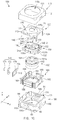
- FIG. 1C is an exploded perspective view of a camera module according to an embodiment of the present disclosure.
- the camera module 100 may include a shield can 110, a stopper 120, a variable aperture 130, an aperture fixing unit 140, a first movable carrier 150, a lens barrel 160, a second movable carrier 180, an aperture driving module 170, and a housing 190.
- the variable aperture 130 may be disposed on the lens barrel 160, and the size of an aperture hole area 130a of the variable aperture 130 may be adjusted by the aperture driving module 170.
- the camera module 100 may change the size of the variable aperture 130 depending on, for example, the currently-set photographing mode.
- the camera module 100 may be adjusted such that the size of the aperture hole area 130a is a first size (e.g., the maximum size) when a first photographing function (e.g., pan-focusing) is executed. Similarly, the camera module 100 may be adjusted such that the size of the aperture hole area 130a is a second size (e.g., the minimum size) when a second photographing function (e.g., zoom-focusing function or out-focusing function) is executed. Further, the size of the aperture hole area 130a may be adjusted to be between the maximum value and the minimum value.
- a first size e.g., the maximum size
- a second photographing function e.g., zoom-focusing function or out-focusing function
- the above-described camera module 100 may have a state in which the variable aperture 130 is disposed in the first movable carrier 150.
- the first movable carrier 150 in turn is coupled to the lens barrel 160 and is disposed on the lens barrel 160. Accordingly, the variable aperture 130 may be moved in the X-axis or Y-axis direction in correspondence to the movement of the lens barrel 160.
- the camera module 100 may include a second movable carrier configured to move the first movable carrier 150 in the Z-axis direction.
- the above-described camera module 100 may minimize the height (i.e.
- the length in the z-axis direction of the camera module 100 by minimizing a gap between an uppermost end of the lens barrel 160 and the aperture hole area 130a of the variable aperture 130 (e.g., there may be no gap, such that part of the uppermost lens of the lens barrel 160 protrudes through the aperture hole area 130a).
- the shield can 110 may cover the camera module 100 from its upper surface to lower surface as a whole.
- the shield can 110 may include an upper surface 111 and shield can side walls 112 disposed at the peripheries of the upper surface 111.
- the bottom of the shield can 110 may be open.
- the upper surface 111 of the shield can 110 may include a shield can hole 110a of a specific size such that at least a portion of the lens 161 disposed at a central portion of the lens barrel 160 may be exposed.
- the shield can side walls 112 may be coupled to the peripheries of the housing 190 so that the shield can 110 and the housing 190 enclose and protect the internal components (e.g., the stopper 120, the variable aperture 130, the aperture fixing unit 140, the first movable carrier 150, the lens barrel 160, the second movable carrier 180, and the aperture driving module 170) of the camera module 100.
- the shield can 110 may be made of metal or another material (e.g., reinforced plastic) having a specified hardness value.
- the stopper 120 may be disposed between the shield can 110 and the variable aperture 130 to prevent the variable aperture 130 from deviating in the positive-Z direction (e.g., the upward direction).
- the stopper 120 may include an upper substrate 125 and leads 124.
- the upper substrate 125 may include a peripheral area 121 having a polygonal band (e.g., rectangular band) shape, a hollow central portion, and a stopper substrate 122 including a stopper hole 120a at the central portion thereof and having a specific size such that the aperture hole area 130a of the variable aperture 130 may be exposed.
- the stopper substrate 122 may be connected and fixed to one side of the peripheral area 121 through connecting portions 123.
- the structure of the stopper 120 may be integrally formed.
- the upper substrate 125 (the peripheral area 121 and the stopper substrate 122), the connecting portion 123, and the leads 124 may be machined from a single piece of metal.
- the stopper substrate 122 may be disposed at the uppermost surface of the stopper 120, and may be spaced apart from the peripheral area 121 by a specific height (e.g., the height of the connecting portion 123). In other words, the stopper substrate 122 is spaced apart from the variable aperture 130 by a specific interval due to the height of the connecting portion 123, such that it allows for upward movement by the variable aperture 130.
- the leads 124 may be formed on sides (e.g., corners) of the peripheral area 121. According to an embodiment, the leads 124 may have a band shape, such that the central portion of the leads are hollow. The leads 124 may be coupled to the sides of the first movable carrier 150 and/or the second movable carrier 180.
- the variable aperture 130 may include two wing parts 130_1 and 130_2.
- the wing parts 130_1 and 130_2 may partially overlap each other.
- the overlapping wing parts 130_1 and 130_2 may be rotatably fixed so that they can rotate within a specific angle range.
- Each of the wing parts 130_1 and 130_2 may include wing holes 131a and 131b having different sizes at the respective central portion thereof.
- the wing holes 131a and 131b may partially overlap each other.
- the wing holes 131a and 131b partially overlap each other to form the central aperture hole area 130a.
- the wing holes 131a and 131b may have irregular shapes where different portions of the shapes have different sizes, so that depending on where the wing holes 131a and 131b overlap, different-sized central aperture hole may be produced.
- the wing hole 131a may have a snowman shape.
- the wing holes 131a and 131b may include a plurality of holes that are spaced apart from each other by a specific interval (e.g., two holes of different diameters that are spaced apart from each other).
- the wing parts 130_1 and 130_2 may be engaged to be moved so that the wing holes 131a and 131b can variously overlap. For example, when the wing parts 130_1 and 130_2 are moved to be closer to each other, such that the overlapping area of the wing parts 130_1 and 130_2 increases, the aperture hole area 130a may become larger. Conversely, when the wing parts 130_1 and 130_2 are moved to be further apart, such that the overlapping area of the wing parts 130_1 and 130_2 decreases, the aperture hole area 130a may become smaller.
- the above-described wing parts 130_1 and 130_2 are seated on one side of the first movable carrier 150.
- the aperture fixing unit 140 may be disposed on a periphery of one side of the variable aperture 130 so that it can cause the rotation of the variable aperture 130.
- the aperture fixing unit 140 may be disposed on one side of the variable aperture 130 and include a lever 139 that can be used to rotate the wing part 130_1.
- a wing holder 132 disposed on the other side of the variable aperture 130 fixes the wing part 130_2 in place.
- the aperture fixing unit 140 may include a cover 141 disposed to cover an upper surface of a corner area of the variable aperture 130, where the cover may prevent deviation of the variable aperture 130 in the Z-axis direction.
- the aperture fixing unit 140 may further include a side lead 142 disposed to overlap a side of the corner area of the variable aperture 130. The side lead 142 may be used to move the lever 139 within a specific angle while preventing deviation of the variable aperture 130 in the X-axis direction or Y-axis direction.
- the first movable carrier 150 may be configured such that the inner center of the first movable carrier 150 is hollow so as to accommodate at least a portion of the lens barrel 160.
- the variable aperture 130 may be seated on and fixed to one side of an upper portion of the first movable carrier 150. Then, the first movable carrier 150 may be coupled to the lens barrel 160.
- a first magnet member 151 and a second magnet member 152 may be disposed on at least two outer sides of the first movable carrier 150. The two outer sides may be adjacent to each other.
- the first and second magnet members 151 and 152 may be used to compensate for shakiness of the camera module 100 when it is in use.
- the first magnet member 151 and the second magnet member 152 may pair with hand-shaking compensation related coils 191 and 192 disposed on two sides of the housing 190, such that the first movable carrier 150 may move in the X-axis or Y-axis direction within the housing 190.
- the interior of the lens barrel 160 has a can shape, and one or more lenses are disposed in the interior of the lens barrel 160.
- the lenses are spaced apart from each other by specific intervals in the Z-direction.
- the upper portion of the lens barrel 160 may taper.
- a lens hole 161a may be disposed at an upper end of the lens barrel 160. At least a portion of the uppermost lens 161 may be exposed through the lens hole 161a.
- the uppermost lens 161 may be convex, such that a portion of the uppermost lens 161 extends beyond the upper surface of the lens barrel 160.
- a fixing recess or a fixing boss 162, to which the first movable carrier 150 or the stopper 120 is fixed, may be disposed on one side of the lens barrel 160.
- a through-hole 180a of a specific size may be provided at a central portion of the second movable carrier 180, and the second movable carrier 180 may include a frame 189 that forms the through-hole 180a, and one or more carrier side walls 181, 182, 183, and 184 extending upwards from peripheries of the frame 189.
- the carrier side walls 181, 182, 183, and 184 may include a first carrier side wall 181, a second carrier side wall 182, a third carrier side wall 183, and a fourth carrier side wall 184.
- the first carrier side wall 181 may include a recess or hole such that the first magnet member 151 disposed on one side of the first movable carrier 150 is exposed.
- the second carrier side wall 182 may include a specific recess or hole such that at least a portion of the second magnet member 152 disposed on another side of the first movable carrier 150 is exposed. As described above, the first magnet member 151 and the second magnet member 152 may be coupled to the coils 191 and 192 to move the lens barrel 160 in the X-axis and/or Y-axis direction.
- the third carrier side wall 183 may include a third magnetic member 188 that cooperates with a coil 193 in the housing 190 to move the lens barrel 160 in the Z-axis direction.
- a least some components of the aperture driving module 170 for the adjustments of the wing parts 130_1 and 130_2 of the variable aperture 130 may be disposed in the fourth carrier side wall 184. A portion of the lens barrel 160, such the lower end of the lens barrel 160, may be seated inside the above-described second movable carrier 180.
- the aperture driving module 170 may be disposed on one side of the variable aperture 130, and may be coupled to the lever 139.
- the aperture driving module 170 may include a support 174 configured to move the lever 139 in a specific direction (e.g., in one direction on a horizontal plane, for example, in the X-axis direction), a fourth magnet member 173 disposed on one side of the support 174, an aperture coil 172 configured to move the fourth magnet member 173 in the specific direction when electric power is supplied, and an aperture driving IC 171 configured to control supply of electric power to the aperture coil 172.
- the fourth magnet member may be called an aperture driving magnet member.
- the aperture driving IC 171 and the aperture coil 172 for example, may be disposed on one side of the housing 190.
- the support 174, in which the fourth magnet member 173 is disposed may be disposed on one side (e.g., the fourth carrier side wall 184) of the second movable carrier 180.
- the support 174 may include a holding hole 706, into which the lever 139 may be inserted.
- the holding hole 706 may have an elongated shape extending in one direction, along which the lever 139 may be moved in the direction (e.g., the X-axis direction).
- the holding hole 706 may further include a guard area so that the support 174 does not interfere with the lever 139 while the lens barrel 160 is moving to compensate for shakiness of the camera module 100.
- the surface area of holding hole 706 may be bigger than the cross-sectional area of the lever 139.
- guard area may correspond to the distance by which the lens barrel 160 is moved during the compensation for shakiness of the camera module 100 in both the +X-axis and -X-axis directions.
- guard areas may be provided on the upper and lower sides of the holding hole 706.
- the housing 190 may include a seating part 198, in which the above-described components (e.g., the stopper 120, the variable aperture 130, the aperture fixing unit 140, the first movable carrier 150, the lens barrel 160, and the second movable carrier 180) are disposed, and housing side walls 90 surrounding the above-described components.
- the seating part 198 may include a seating part hole 190a, through which a central portion of the lens barrel 160 is exposed downwards.
- An image sensor for example, may be disposed under the seating part hole 190a.
- the housing side walls 90 may be provided at peripheries of the seating part 198.
- the housing side walls 90 may include a first housing side wall 91 having the first coil 191.
- the first coil 191 cooperates with the first magnet member 151 disposed in the first movable carrier 150 to move the lens barrel 160 in the X-axis direction.
- the housing side walls 90 further includes a second housing side wall 92 having the second coil 192.
- the second coil 192 cooperates with the second magnet member 152 disposed in the first movable carrier 150 to move the lens barrel 160 in the Y-axis direction.
- the housing side walls 90 further includes a third housing side wall 93 having a third coil 193 that cooperates with the third magnet member 188 disposed in the second movable carrier 180 to move the lens barrel 160 in the Z-axis direction. And the housing side walls 90 may further include a fourth housing wall 94 in which the aperture coil 172 is disposed. At least some of the housing side walls 90 may protect the at least some of the components described above in conjunction with the shield can side walls 112.
- the above-described camera module 100 may have a variable aperture 130.
- the variable aperture 130 may be disposed on the first movable carrier 150 so that it is moved together as the lens barrel 160 is moved. Accordingly, the spatial relationship between the lens barrel 160 and the variable aperture 130 may be maintained regardless of the movement of the lens barrel 160 (e.g., movement in the X-axis/Y-axis direction to compensate for shakiness or movement in the Z-axis direction for auto-focusing). Further, the camera module 100 according to the present disclosure may minimize the vertical thickness of the camera module 100 by aligning the aperture hole area 130a of the variable aperture 130 with the uppermost lens 161 disposed inside the lens barrel 160 and extending at least a portion of the uppermost lens 161 through the aperture hole area 130a.
- the camera module 100 may include a guard area in the holding hole 706, in which the lever 139 is disposed, so that the support 174 does not interfere with the lever 139 during when the lens barrel 160 is moving to compensate for shakiness.
- FIG. 2A is a perspective view illustrating a camera module according to another embodiment of the present disclosure.
- FIG. 2B is a perspective view illustrating a stopper according to another embodiment of the present disclosure.
- the camera module 1100 of another embodiment of the present disclosure may include a shield can 110, a modified stopper 1200, a variable aperture 130, a lens barrel 160, and a housing 190. Additionally, the camera module 1100 may further include a first movable carrier, on which the lens barrel 160 is mounted, a second movable carrier, on which the first movable carrier is seated, and an aperture driving module configured to adjust the size of an aperture hole of the variable aperture 130.
- the shield can 110 in this embodiment may have a shape that is substantially same as or similar to the shape of the shield can described above in FIGS. 1A to 1C . Further, the variable aperture 130, the lens barrel 160, and the housing 190 also may be the same as or similar to those described above in FIGS. 1A to 1C .
- the modified stopper 1200 may be disposed between the shield can 110 and the variable aperture 130 to prevent the variable aperture 130 from deviating in the Z-axis direction (e.g., the upward direction).
- the modified stopper 1200 may include a stopper substrate 1250, connecting portions 1223a, 1223b, and 1223c, an upper substrate 1230, and leads 1224.
- the upper substrate 1230 may include a peripheral area 1221 having a polygonal band shape (e.g., rectangular), and a hollow central through part 1222.
- a polygonal band shape e.g., rectangular
- the connecting portions 1223a, 1223b, and 1223c may have specific vertical heights and may be disposed at peripheries of the through part 1222.
- the connecting portions 1223a, 1223b, and 1223c may be provided to support the stopper substrate 1250 so that the stopper substrate 1250 is separated from the upper substrate 1230 in the Z-axis direction by the specific height.
- at least one of the connecting portions 1223a, 1223b, and 1223c may include a first lead 1223_1 contacting the upper surface of the stopper substrate 1250, and a second lead 1223_2 contacting the lower surface of the stopper substrate 1250. Accordingly, one side of the stopper substrate 1250 may be inserted and seated between the first lead 1223_1 and the second lead 1223_2, and the stopper substrate 1250 may be fixed by the connecting portions 1223a, 1223b, and 1223c.
- the stopper substrate 1250 may include a substrate area 1225, the peripheries of which are coupled to the connecting portions 1223a, 1223b, and 1223c, and a stopper hole 1220a provided at a central portion of the stopper substrate 1250.
- the stopper hole 1220a may have a specific size such that the aperture hole area 130a of the variable aperture 130 can be exposed through the stopper hole 1220a.
- the stopper substrate 1250 may be inserted or removed from the connecting portions 1223a, 1223b, and 1223c from the side of the peripheral area 1221 that does not have a connecting portion.
- the connecting portions 1223a, 1223b, and 1223c may be integrally formed with the peripheral area 1221.
- the above-mentioned modified stopper 1200 may allow the stopper substrate 1250 to be assembled after the variable aperture 130 is assembled in the first movable carrier, because the stopper substrate 1250 and the upper substrate 1230 are separate pieces. This may be helpful in the manufacturing process for the camera module 100.
- FIG. 3 is views illustrating a variable aperture and a lens barrel according to an embodiment of the present disclosure.
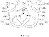
- FIG. 4A is a perspective view illustrating a variable aperture according to an embodiment of the present disclosure.
- FIG. 4B is a top view illustrating a first movable carrier, on which a variable aperture is mounted, and a lens barrel according to an embodiment of the present disclosure.
- FIG. 4C is a perspective view illustrating a first state of a variable aperture according to an embodiment of the present disclosure.
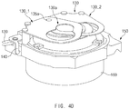
- FIG. 4D is a perspective view illustrating a second state of a variable aperture according to an embodiment of the present disclosure.
- the variable aperture 130 may be disposed on one side of the lens barrel 160.
- the lens barrel 160 may include a lower barrel 61 having a cylindrical shape of a first diameter, a middle barrel 62 having a second diameter which gradually tapers, a protrusion 64 having a circular band shape that protrudes from the exterior of the middle barrel 62, and an upper barrel 63 disposed on the protrusion 64 and having a diameter that is smaller than that of the middle barrel 62, where the diameter of the upper barrel 63 also gradually tapers.
- a lens hole 161a, through which external light is introduced into the lens barrel 160, may be disposed on an upper surface of the upper barrel 63.
- Notches may be disposed on an inner wall of the lower barrel 61. The peripheries of lenses may be received by these notches so that the lenses are held in place. Similarly, notches also may be disposed on inner walls of the middle barrel 62 and the upper barrel 63.
- Fixing bosses 162 each having a recess of a specific size may be disposed on one side of an upper surface of the protrusion 64.
- the fixing bosses 162, for example, may be used for coupling to the stopper 120.
- sides of the connecting portions 123 provided in the stopper 120 may be seated on the recesses of the fixing bosses 162.
- the variable aperture 130 may be seated on the protrusion 64.
- the variable aperture 130 may include a first wing part 130_1 and a second wing part 130_2.
- the first wing part 130_1 may include a first wing 134a, a first wing support 133a connected to the first wing 134a, a first wing holder 132a connected to the first wing support 133a, a lever 139, and a connection boss 135a.
- the second wing part 130_2, for example, may include a second wing 134b, a second wing support 133b connected to the second wing 134b, a second wing holder 132b connected to the second wing support 133b, and a connection hole 135b.
- the first wing 134a may have various shapes, such as a polygonal shape.
- a first upper hole 137a2 and a first lower hole 137a1 may be disposed on the first wing 134a.
- the diameter of the first upper hole 137a2 and the diameter of the first lower hole 137a1 may be different.
- the diameter of the first upper hole 137a2 may be smaller than the diameter of the first lower hole 137a1.
- the shape of the first upper hole 137a2 and the first lower hole 137a1 together may resemble a snowman.
- the first upper hole 137a2 in manufacturing the first wing 134a, may be a circular hole of a first size created on the first wing 134a.
- the first lower hole 137a1 which is another circular hole of a second size (e.g., which is the same as or larger than the first size), may be created on the first wing 134a.
- the first upper hole 137a2 and the first lower hole 137a1 may be spaced apart from each other.
- the second upper hole 137b2 and the second lower hole 137b1 may be similarly created on the second wing 134b.
- the first lower hole 137a1 and the second lower hole 137b1 may overlap each other.
- the first upper hole 137a2 and the second upper hole 137b2 may overlap each other.
- the holes 137a1, 137a2, 137b1, and 137b2 may be variously disposed on the center point of the lens hole 161a.
- the first upper hole 137a2 may be disposed on the lens hole 161a while overlapping the second upper hole 137b2 provided in the second wing 134b.
- the first wing support 133a may extend from a periphery of one side of the first wing 134a while having a specific angle (e.g., a vertical angle) with a surface of the first wing 134a.
- the first wing support 133a has a partially cylindrical shape and may extend toward the lens barrel 160.
- a lower side of the first wing support 133a may rest on the protrusion 64.
- the first wing 134a may be spaced apart from the front surface of the upper barrel 63 by the height of the first wing support 133a.
- the first wing holder 132a is connected to a lower side of the first wing support 133a and may extend outwards. Accordingly, the first wing holder 132a may prevent movement by the first wing part 130_1 in the Z-axis direction when the first wing holder 132a abuts the inner surface of the stopper 120.
- the first wing holder 132a may be disposed on one side of an upper portion of the first movable carrier 150.
- the lever 139 may protrude from one side of the first wing holder 132a.
- the lever 139 may be moved in specific directions (e.g., in the +X-axis and -X-axis directions) by the aperture driving module 170.
- the lever 139 may transmit a force that moves the first wing holder 132a, and the first wing 134a connected to the first wing support 133a may be rotated due to the force.
- the first upper hole 137a2 and/or the first lower hole 137a1 may be positioned on the lens hole 161a in correspondence to the rotation of the first wing 134a.
- connection boss 135a may be disposed on one side of the first wing 134a, and may be disposed in the area where the first wing 134a overlaps the second wing 134b. According to an embodiment, the connection boss 135a may protrude from the first wing 134a, and may be inserted into the connection hole 135b provided on one side of the second wing 134b. The connection boss 135a and the connection hole 135b may allow for rotation of the first wing 134a and the second wing 134b. Accordingly, a rotational force is transmitted to the connection boss 135a while the first wing 134a is rotated, and the second wing 134b may also be rotated in a specific angle range in correspondence to the movement of the connection boss 135a.
- the second wing 134b may have a shape that is substantially the same as or similar to that of the first wing 134a, except for the connection hole 135b.
- the second wing 134b may include a second upper hole 137b2 and a second lower hole 137b1.
- the second upper hole 137b2 and the second lower hole 137b1 may connect to each other to form a single continuous hole, as shown in FIG. 4A , and the second upper hole 137b2 may have a diameter that is larger than that of the second lower hole 137b1.
- the second upper hole 137b2 or the second lower hole 137b1 may be disposed on the lens hole 161a.
- the second wing support 133b is disposed on one side of the second wing 134b, and may extend perpendicularly from the surface of the second wing 134b.
- the second wing holder 132b may be connected to a lower side of the second wing support 133b.
- a lower side of the second wing holder 132b may be seated on an upper surface of the protrusion 64 of the lens barrel 160, and may move along the upper surface of the protrusion 64 in a specific angle range.
- the second wing support 133b has a shape that is similar to or the same as that of the first wing support 133a, and may be disposed to be symmetrical to the first wing support 133a with respect to the lens hole 161a.
- the second wing holder 132b may be disposed under the second wing support 133b.
- the second wing holder 132b may prevent movement by the second wing part 130_2 in the Z-axis direction when the second wing holder 132b abuts the inner surface of the stopper 120.
- the second wing holder 132b may have a shape that is substantially similar to or the same as that of the first wing holder 132a, except for the lever 139.
- the second wing holder 132b may be seated on an upper surface of the first movable carrier 150.
- connection hole 135b may be provided on one side of the second wing 134b and may have a specific length.
- the connection boss 135a provided in the first wing 134a may be inserted into the connection hole 135b.
- the connection boss 135a seated in the connection hole 135b may be moved along an inner peripheral surface of the connection hole 135b.
- the connection hole 135b may have a curved shape. Accordingly, while the first wing 134a is rotated, the second wing 134b may also be rotated because the connection boss 135a moves along the curved inner peripheral surface of the connection hole 135b.
- the size of the overlapping area of the first wing part 130_1 and the second wing part 130_2 may vary according to the control of the aperture driving module 170 coupled to the lever 139.
- the first wing part 130_1 and the second wing part 130_2 are maximally overlapping, the first lower hole 137a1 of the first wing part 130_1 and the second lower hole 137b1 of the second wing part 130_2 overlap each other on the lens hole 161a.
- the periphery of the first wing 134a contacts a boss formed in the second wing support 133b (not shown) rotation of the first wing 134a and the second wing 134b may be stopped.
- the first upper hole 137a2 of the first wing part 130_1 and the second upper hole 137b2 of the second wing part 130_2 overlap each other on the lens hole 161a. Then, the overlapping of the first wing 134a and the second wing 134b is minimal when the connection boss 135a is stopped by the connection hole 135b.
- the first movable carrier 150 may be fixedly coupled to the middle barrel 62 of the lens barrel 160, such that the protrusion 64 and the upper barrel 63 upwards protrudes from the first movable carrier 150, and the lower barrel 61 downwards protrudes from the first movable carrier 150.
- Sides of the wing holders of the variable aperture 130 may be seated on the first movable carrier 150.
- the first wing holder 132a of the first wing 134a may be seated on one side of the first movable carrier 150, and the aperture fixing unit 140 may be disposed on the upper side of the first movable carrier 150 while covering the first wing holder 132a. Then, the lever 139 extending from the first wing holder 132a may protrude through a recess provided in the aperture fixing unit 140.
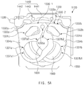
- FIG. 5A is a top view illustrating a camera module including a modified variable aperture according to an embodiment of the present disclosure.
- FIG. 5B is views related to a jig process of a camera module including a modified variable aperture according to an embodiment of the present disclosure.
- another embodiment of the camera module 1100 may include a modified variable aperture 1330, an aperture fixing unit 1440, a lens barrel 1660, and a first movable carrier 1550. Additionally, the camera module 1100 may further include other above-described other components such as the shield can and the second movable carrier.
- the aperture fixing unit 1440 may include a body 1441, cover areas 1442 configured to cover the first wing holder 1332a and the second wing holder 1332b of the modified variable aperture 1330, and holes 1443, which may be fitted with and fixed to protrusions provided on one side of the first movable carrier 1550.
- the modified variable aperture 1330 may include a first wing part 1330_1 and a second wing part 1330_2. They may at least partially overlap each other.
- the first wing part 1330_1 may include a first wing 1334a, a first wing support 1333a connected to the first wing 1334a, a first wing holder 1332a connected to the first wing support 1333a, a lever 1339, and a connection boss 1335a.
- the second wing part 1330_2 may include a second wing 1334b, a second wing support 1333b connected to the second wing 1334b, a second wing holder 1332b connected to the second wing support 1333b, and a connection hole 1335b, into which a connection boss 1335a is inserted.
- the first wing support 1330_1, the first wing holder 1332a, the lever 1339, and the connection boss 1335a may be substantially the same as or similar to the first wing support, the first wing holder, the lever, and the connection boss described above in FIG. 4A .
- the second wing support 1330_2, the second wing holder 1332b, and the connection hole 1335b may be substantially the same as or similar to the second wing support, the second wing holder, and the connection hole described above in FIG. 4A .
- the first wing 1334a may include a first upper hole 1337a2, a first lower hole 1337a1, and a first jig insertion hole 1331c.
- a jig may be inserted into the jig insertion hole 1331c.
- the first upper hole 1337a2 and the first lower hole 1337a1 may be disposed in a lower area of the first wing 1334a.
- the first upper hole 1337a2 and the first lower hole 1337a1 may be substantially the same as or similar to the first upper hole and the first lower hole described above in FIG. 4A .
- the first jig insertion hole 1331c may be disposed in an upper area of the first wing 1334a. Accordingly, a portion of the lens barrel 1660 disposed under the first jig insertion hole 1331c may be exposed by the first jig insertion hole 1331c.
- the size or shape of the first jig insertion hole 1331c may vary, depending on the design of the camera module 1100.
- the second wing 1334b may have a shape that is substantially the same as or similar to that of the first wing 1334a, except for the connection hole 135b, into which the connection boss 1335a is inserted.
- the second wing 1334b may include a second upper hole 137b2, a second lower hole 137b1, and a second jig insertion hole 1331d.
- the second jig insertion hole 1331d may be disposed in an upper area of the second wing 1334b.
- the jig related to the assembly of the camera module 1100 may include a lower jig 402, on which the camera module 1100 is disposed, and an upper jig 401 that presses the camera module 1100 downwards.
- the upper jig 401 may include a disk 410 and at least one column 420.
- the disk 410 may have a size that is smaller than the size of the shield can hole 1110a disposed at a central portion of the shield can 1110.
- the columns 420 may be four columns disposed under the disk 410.
- the columns may pass through the first upper hole 1337a2, the second upper hole 1337b2, the first jig insertion hole 1331c, and the second jig insertion hole 1331d in order to press the lens barrel 1660 downwards.
- the stopper substrate 1250 of the stopper 1200 may support the lens barrel 1660 after the upper jig 401 is removed
- the lower jig 402 may include a central disk 440 facing the seating part hole 190a provided in the housing 190, and a support substrate 430 disposed under the central disk 440. Additionally, at least one recess may be disposed in a corner area of the support substrate 430, such that the recess couples to a boss disposed under the housing 190.
- the substrate 430 may include four recesses for four bosses of the housing 190.
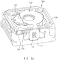
- FIG. 6A is a perspective view illustrating a first state of a camera module according to a change of a variable aperture according to an embodiment of the present disclosure.
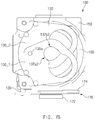
- FIG. 6B is a perspective view illustrating a second state of a camera module according to a change of a variable aperture according to an embodiment of the present disclosure.
- the shield can 110 having a shield can hole 110a surrounds the outside of the camera module 100 and the housing 190 may be coupled to the shield can 110 to provide an enclosure for the camera module 100.
- the lens barrel 160 which is coupled to the first movable carrier 150 and the second movable carrier 180, may be seated in the housing 190.
- the stopper 120 a central portion of which protrudes through the shield can hole 110a, may be disposed inside the housing 190.
- the peripheral area 121 and the leads 124 of the upper substrate 125 of the stopper 120 may be disposed within the shield can 110, while the stopper substrate 122 and the connecting portions 123 of the upper substrate 125 may protrude through the shield can hole 110a.
- the stopper hole 120a may coincide with the lens hole 161a of the lens barrel 160 such that external light may enter the lens hole 161a.
- the size of the stopper hole 120a may be the same as, smaller, or larger than the size of the lens hole 161a.
- the aperture driving module 170 may be disposed on one side of the housing 190. A portion of a side of the shield can 110 may be removed such that at least a portion (e.g., the aperture coil 172 or the aperture driving IC 171) of the aperture driving module 170 is exposed.
- the exposed aperture coil 172 may be connected to a control unit of the electronic device, in which the camera module 100 is mounted. An electrical current may be supplied to the aperture coil 172 under the control of the aperture driving IC 171. In that case, the fourth magnet member 173 disposed in the support 174 may move the support 174 in a first direction. When another current in the reverse direction is applied, the fourth magnet member 173 disposed in the support 174 may move the support 174 in a second direction. In turn, the lever 139 may be moved in the first and second direction.
- the first wing part 130_1 and the second wing part 130_2 may be moved to increasingly overlap, to the point where the first lower hole 137a1 of the first wing 134a and the second lower hole 137b1 of the second wing 134b completely overlap each other. Accordingly, the first lower hole 137a1 and the second lower hole 137b1 may provide a relatively large aperture for the camera module 100.
- the first wing part 130_1 and the second wing part 130_2 may be moved so that their overlap decreases, to the point where the first upper hole 137a2 of the first wing 134a and the second upper hole 137b2 of the second wing 134b completely overlap each other. Accordingly, the first upper hole 137a2 and the second upper hole 137b2 may provide a relatively small aperture for the camera module 100.
- the camera module 100 may adjust the aperture for the transmission of light, by using the variable aperture 130 disposed on the lens barrel 160.
- the state shown in FIG. 6A may be appropriate for a first photographing function (e.g., pan-focusing) that requires a relatively large amount of light
- the state shown in FIG. 6B may be appropriate for a second photographing function (e.g., zoom-focusing) that requires a relatively small amount of light.
- FIG. 6C is a top view illustrating a lens barrel according to an embodiment of the present disclosure.
- the camera module may include a lens barrel 160, a variable aperture 130, at least one side of which is fixed to an upper side of the lens barrel 160, a first magnet member 151 and a first coil 191, a second magnet member 152 and a second coil 192, a third magnet member 188 and a third coil 193, and a fourth magnet member 173 and an aperture coil 172.
- the first magnet member 151 and the first coil 191 may compensate vertical shakiness of the camera module (for example, when the user's hand holding the camera module is unsteady), by moving the lens barrel 160 downwards or upwards. Because the variable aperture 130 is coupled with the lens barrel 160, the variable aperture 130 may be moved upwards and downwards together with the lens barrel 160.
- the second magnet member 152 and the second coil 192 may compensate horizontal shakiness of the camera module by moving the lens barrel 160 leftwards or rightwards by a specific distance.
- the third magnet member 188 and the third coil 193 may support an auto-focusing function by moving the lens barrel 160 in the Z-axis direction (the Z-axis being orthogonal to the plane of the figure).
- the fourth magnet member 173 and the aperture coil 172 may be used to adjust the size of the aperture hole of the variable aperture 130, as described above.
- the camera module may a module to compensate for shakiness of the camera module.
- the compensation module may include a first compensation module (e.g., the first coil 191 and the first magnet member 151) disposed on a first side surface of the lens barrel 160 (or a carrier or a housing surrounding the lens barrel 160) to compensate shakiness in the X-axis direction, and a second compensation module (e.g., the second coil 192 and the second magnet member 152) disposed on a second side surface of the lens barrel 160 to compensate shakiness in the Y-axis direction.
- the first and second side surfaces may be adjacent to each other and form a ninety degree angle.
- the camera module may include an auto-focusing module AF disposed on a third side surface of the lens barrel 160.
- the AF module may include a third magnet member 188 and a third coil 193.
- the camera module may include an aperture driving module disposed on a fourth side surface of the lens barrel 160.
- the aperture driving module for example, may include a fourth magnet member 173 and an aperture coil 172.
- the camera module may support variable aperture, auto focus, and shakiness compensation in two axes without generating interferences between the magnets or coils used in the modules for variable aperture, auto focus, and shakiness compensation.
- a camera module or an electronic device may include a lens barrel including at least one lens and a lens hole such that light may be input through the lens hole, a pair of variable apertures including an aperture hole area arranged on the lens hole and configured to adjust the size of a hole by a physical force applied to a lever; a hand-shaking compensating module disposed on a first side surface and a second side surface of the lens barrel and configured to compensate hand shaking in a first axis direction and a second axis direction, an auto-focusing module disposed on a third side surface of the lens barrel and configured to support a motion of the lens barrel in a third axis direction, related to the auto-focusing function, and an aperture driving module disposed on a fourth side surface of the lens barrel and configured to adjust the aperture hole of the variable aperture.
- the hand-shaking compensating module may include a magnet member and a coil on a first side surface of the lens barrel and a second side surface that is adjacent to the first side surface and forming a specific angle with the first side surface on a horizontal plate, and the hand-shaking is compensated by moving the lens barrel in at least one of the X-axis and Y-axis directions on a horizontal plane.
- the autofocusing module may include a magnet member and a coil on a third side surface that is adjacent to the second side surface and forming a specific angle with the second side surface, and may be disposed to adjust the focusing by moving the lens barrel in the Z-axis direction.
- the aperture driving module may include a magnet member and a coil on a fourth side surface that is adjacent to the first side surface and forming a specific angle with the first side surface, and may be disposed to adjust the size of the aperture hole area through a movement in the X-axis direction.
- FIG. 7A is a perspective view illustrating a variable aperture of a first state according to an embodiment of the present disclosure.
- FIG. 7B is a top view illustrating a variable aperture of a second state according to an embodiment of the present disclosure.
- the lever 139 inserted into the holding hole of the support 174 may be moved rightwards in correspondence to the movement of the support 174. Accordingly, the first wing part 130_1 connected to the lever 139 may be rotated counterclockwise. In correspondence to the rotation of the first wing part 130_1, the second wing part 130_2 connected through the connection boss 135a may be rotated clockwise. Accordingly, as illustrated, the first lower hole 137a1 of the first wing and the second lower hole 137b1 of the second wing may overlap each other.
- the lever 139 inserted into the holding hole of the support 174 may be moved leftwards in correspondence to the movement of the support 174. Accordingly, the first wing part 130_1 connected to the lever 139 may be rotated clockwise. In correspondence to the rotation of the first wing part 130_1, the second wing part 130_2 connected through the connection boss 135a may be rotated counterclockwise. Accordingly, as illustrated, the first upper hole 137a2 of the first wing and the second upper hole 137b2 of the second wing may overlap each other.
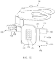
- FIG. 7C is a perspective view illustrating a variable aperture and an aperture driving module according to an embodiment of the present disclosure.
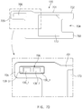
- FIG. 7D is a side view illustrating an aperture driving module according to an embodiment of the present disclosure.
- the aperture driving module 170 may include a support 174, an aperture driving IC 171, a fourth magnet member 173, and an aperture coil 172.
- the support 174 may include a central body 701, on which the fourth magnet member 173 is seated, a first extending portion 702 extending from an end of one side of the central body 701 in one direction, a second extending portion 703 extending in the same direction and disposed in parallel to the first extending portion 702, a holding recess 704 defined by the first extending portion 702 and the second extending portion 703, and a lever holder 705 in which the holding hole 706 is formed.
- the lever holder 705 and the first extending portion 702 may be on opposite sides of the central body 701.
- the holding hole 706 may comprise several regions.
- the holding hole 706 may include a first location 139_1 which is where the lever 139 is located when the first upper hole 137a2 and the second upper hole 137b2 overlap each other.
- the holding hole 706 may also include a second location 139_2 which is where the lever 139 is located when the first lower hole 137a1 and the second lower hole 137b1 overlap each other.
- the holding hole 706 may further include a first guard hole area 139_3 to the left of the first location 139_1 and a second guard hole area 139_4 to the right of the second location 139_2.
- the first guard hole area 139_3 and the second guard hole area 139_4 may be large enough such that when the camera module 100 is compensating for shakiness, the lever 139 does not come into contact with the lever holder 705.
- the first guard hole area 139_3 and the second guard hole area 139_4 may have widths of 0.3 mm.
- the lever 139 in relation to the compensation of shakiness in the Y-axis direction, the lever 139 may protrude into the lever holder 705 by a distance greater than the designed Y-axis compensation distance, such that the lever 139 does not disengage from the lever holder 705, even when Y-axis compensation occurs.
- the camera module may be designed such that the lever 139 exceeds the lever holder 705 by 0.4 mm.
- a processor (or a driving IC of the aperture driving module 170) of an electronic device, in which the camera module 100 is mounted, may operate the lever 139 such that a marginal area is left in anticipation of shakiness compensation. For example, in order to bring the variable aperture 130 into a first state (e.g., the state where the lower holes in the wing parts overlap), the processor may control the aperture driving module 170 such that the support 174 moves in a first direction by a first distance (e.g., the distance that make the aperture hole as large as possible).
- a first distance e.g., the distance that make the aperture hole as large as possible
- the processor may move the support 174 by a second distance (e.g., a distance related to the compensation of hand shaking) in a second direction opposite the first direction such that the first guard hole area 139_3 will have a sufficiently large width.
- the processor may control the aperture driving module 170 such that the support 174 moves in the second direction by a third distance (e.g., the distance that make the aperture hole as small as possible).
- the processor may move the support 174 by a fourth distance (e.g., a distance related to the compensation of hand shaking) in the first direction such that the second guard hole area 139_4 will have a sufficiently large width.
- FIG. 7E is a perspective view illustrating parts of a modified variable aperture and an aperture driving module according to an embodiment of the present disclosure.
- the camera module 100 may include a lever 139 disposed on one side of the modified variable aperture 1300, and the lever 139 may be inserted into the holding hole 706 of the lever holder 705.
- the modified variable aperture 1300 may further include a jig insertion hole, in addition to the upper and lower holes constituting the aperture hole.
- the aperture driving module 170 may include a support 174, by which the lever 139 is inserted into the holding hole 706, and a fourth magnet member 173 may be disposed on one side of the support 174. Additionally, as described above, the aperture driving module 170 may further include an aperture coil that cooperates with the fourth magnet member 173, and an aperture driving IC.
- FIG. 8A is a view illustrating various examples of a first adjustment state of an aperture hole area of a variable aperture according to an embodiment of the present disclosure.
- FIG. 8B is a view illustrating various examples of a second adjustment state of an aperture hole area of a variable aperture according to an embodiment of the present disclosure.
- FIG. 8C is a view illustrating various examples of a third adjustment state of an aperture hole area of a variable aperture according to an embodiment of the present disclosure.
- FIG. 8D is a view illustrating various examples of a fourth adjustment state of an aperture hole area of a variable aperture according to an embodiment of the present disclosure;
- a first adjustment state 801 of the aperture hole area 130a provides a large aperture hole as the first lower hole 137a1 of the first wing 134a and the second lower hole 137b1 of the second wing 134b overlap each other.
- the aperture driving module 170 may operate the lever 139 disposed in the first wing part 130_1 such that the first wing 134a and the second wing 134b rotate inward. In doing so, the lever 139 may be moved downwards with respect to the illustrated drawing and may be moved by a maximum movable distance. When the maximum movable distance is reached, the aperture fixing unit 140 may stop the movement of the lever 139.
- the support 174 of the aperture driving module 170 may be designed so that the movement of the lever 139 does not exceed the maximum movable distance.
- a second adjustment state 802 of the aperture hole area 130a provides a star-shaped aperture hole as portions of the first lower hole 137a1, the second lower hole 137b1, the second upper hole 137b2, and the first upper hole 137a2 overlap each other.
- the aperture driving module 170 may operate the lever 139 disposed in the first wing part 130_1 such that the first wing 134a and the second wing 134b move outwards from the first adjustment state 801.
- the lens hole 161a may be partially covered by the variable aperture 130.
- the second adjustment state 802 may be an intermediate state between the first adjustment state 801 and the fourth adjustment state 804 described in FIG. 8D . Further, the second adjustment state 802 may be used for specific photographing functions.
- a third adjustment state 803 of the aperture hole area 130a may provide a diamond-shaped aperture hole as portions of the first lower hole 137a1, the second lower hole 137b1, the second upper hole 137b2, and the first upper hole 137a2 overlap each other.
- the aperture driving module 170 may operate the lever 139 disposed in the first wing part 130_1 such that the first wing 134a and the second wing 134b move outwards from the second adjustment state 802.
- the aperture provided in the third adjustment state 803 may be smaller than that provided in the second adjustment state 802.
- the third adjustment state 803 may be an intermediate state between the first adjustment state 801 and the fourth adjustment state 804 described in FIG. 8D . Further, the third adjustment state 803 may be used for specific photographing functions.
- a fourth adjustment state 804 of the aperture hole area 130a may provide a small aperture hole as the first upper hole 137a2 of the first wing 134a and the second upper hole 137b2 of the second wing 134b overlap each other.
- the aperture driving module 170 may operate the lever 139 disposed in the first wing part 130_1 such that the first wing 134a and the second wing 134b rotate outward by a maximum angle.
- the fourth adjustment state 804 may provide the smallest possible aperture hole.
- the fourth adjustment state 804 may be temporarily fixed as the corresponding photographing function is executed.
- the above-described second adjustment state 802 may be the state in which the lever 139 is moved from the first adjustment state 801 by 0.4 mm.
- the above-described third adjustment state 803, for example, may be the state in which the lever 139 is moved from the first adjustment state 801 by 0.6 mm.
- the above-described fourth adjustment state 804, for example, may be the state in which the lever 139 is moved from the first adjustment state 801 by 0.7 mm. These distances may vary depending on, for example, the size of the camera module 100.
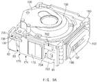
- FIG. 9A is a perspective view illustrating a camera module including a second movable carrier according to an embodiment of the present disclosure
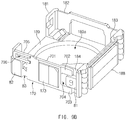
- FIG. 9B is a perspective view in a first direction illustrating a second movement carrier according to an embodiment of the present disclosure
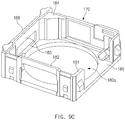
- FIG. 9C is a perspective view in a second direction illustrating a second movement carrier according to an embodiment of the present disclosure.
- the camera module 100 may include a second movable carrier 180 in which the lens barrel 160 is seated, and an aperture driving module 170 configured to drive the variable aperture 130.
- the second movable carrier 180 may include the carrier side walls 181, 182, 183, and 183, the through-hole 180a, and the frame 189, which have been described above.
- the second movable carrier 180 may be moved in an upward/downward direction (e.g. the Z-axis direction).
- the second movable carrier 180 may include the third magnet member 188.
- the third coil 193 and the focusing driving IC 197 disposed on one side of the housing 190 may face the third magnet member 188. Accordingly, if electric power is supplied to the third coil 193, the third magnet member 188 may interact with the third coil 193 to move the second movable carrier 180 upwards and downwards. While the second movable carrier 180 is moved upwards and downwards by the third magnet member 188, the aperture driving module 170 disposed on one side of the second movable carrier 180 may also be moved.
- the aperture driving module 170 in which some configurations are disposed on one side of the second movable carrier 180, may include a fourth magnet member 173 related to driving of the lever 139 of the variable aperture 130.
- the aperture coil 172, the aperture driving IC, and the like of the aperture driving module 170, which interact with the fourth magnet member 173, may be disposed in the housing 190.
- the second movable carrier 180 may include a first step 81, a second step 82, and a seating recess 83 such that the support 174 of the aperture driving module 170 may be seated.
- the seating recess 83 may have a shape corresponding to the shape of the support 174.
- the first step 81 may be disposed on one side of the seating recess 83, and the second step 82 may be disposed on an opposite side of the seating recess 83.
- the first step 81 may protrude from a corner of one side wall of the second movable carrier 180 toward a central portion of the side wall.
- the first step 81 may be disposed in parallel to the recess 704 formed by the first extending portion 702 and the second extending portion of the support 174.
- the second step 82 may have a shape that supports one side (e.g., the lower side) of the lever holder 705 of the support 174.
- FIG. 10A is a side view illustrating a first state of a Z-axis movement of a camera module according to an embodiment of the present disclosure.
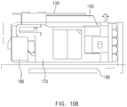
- FIG. 10B is a side view illustrating a second state of a Z-axis movement of a camera module according to an embodiment of the present disclosure.
- the variable aperture 130 positioned on the lens barrel 160 may be located at a first height from the bottom of the housing 190.
- Some components of the aperture driving module 170 may be disposed adjacent to the bottom of the housing 190.
- the variable aperture 130 may be located below the upper surface of the shield can 110.
- the stopper 120 positioned on the upper side of the variable aperture 130 may be disposed at a height that is substantially similar to the height of the upper surface of the shield can 110.
- the lens barrel 160 may be moved in the Z-axis direction, such that at least a portion (e.g., the lower portion) of the lens barrel 160 may be disposed to be spaced apart from the seating part hole of the housing 190 by a specific height.
- the variable aperture 130 disposed on the lens barrel 160 may be located at a second height (e.g., above the first height) from the bottom of the housing 190.
- the second movable carrier 180 may be disposed to be spaced apart from the bottom of the housing 190 by the specific height, and correspondingly, some components of the aperture driving module 170 disposed in the second movable carrier 180 may be spaced apart from the bottom of the housing 190 by the specific height.
- variable aperture 130 may be disposed at the same height as the upper surface of the shield can 110. Accordingly, the stopper 120 may be disposed at a height that is higher than the upper surface of the shield can 110 by protruding through the shield can hole.
- the second movable carrier 180 may move toward the bottom of the housing 190 or in the opposite direction. If the auto-focusing function of the camera module 100 is executed, a control unit of the camera module 100 or the electronic device, in which the camera module 100 is mounted, may supply electric current of different directions to the third coil 193 such that the second movable carrier 180 moves in the +Z or -Z-axis direction.
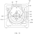
- FIG. 11 is a top view illustrating a shakiness compensation operation of a camera module according to an embodiment of the present disclosure.
- the camera module 100 may include a first coil 191 configured to generate a motion in the X-axis direction, and a second coil 192 configured to generate a motion in the Y-axis direction.
- the first coil 191 and the second coil 192 may be disposed on two sides of the housing 190, and may be disposed on an inner wall of the housing 190, which may face an outer wall of the first movable carrier 150.
- the first magnet member 151 may be disposed in one side of the first movable carrier 150 to face the first coil 191.
- the second magnet member 151 may be disposed in another side of the first movable carrier 150 to face the second coil 192.
- the variable aperture 130 may be disposed on the lens barrel 160. Although FIG. 11 shows that the variable aperture 130 is in a first adjustment state 801, the present disclosure is not limited thereto.
- the variable aperture 130 may be supported by one side of the lens barrel 160, and may have the same motion as the lens barrel 160 when the first movable carrier 150 moves in the X-axis direction and/or the Y-axis direction to compensate for shakiness.
- Some components such as the lens barrel 160, the variable aperture 130, and the first movable carrier 150 of the camera module 100 may move in the +X-axis direction due to force generated by the interaction between the first coil 191 and the first magnet member 151.
- the +X-axis direction is shown FIG. 11 as the upwards direction.
- the first coil 191 and the first magnet member 151 may be supplied with electric power such that an attractive force is generated between them.
- the first movable carrier 150 including the first magnet member 151 may be moved toward the housing 190, and the lens barrel 160 may be moved in an upward direction.
- the lens barrel 160 may be moved in an upward direction by 0.2 mm. The movement distance of the lens barrel 160 may vary according to the size of the camera module 100.
- Some components such as the lens barrel 160, the variable aperture 130, and the first movable carrier 150 of the camera module 100, may move in the -X-axis direction due to force generated by the interaction between the first coil 191 and the first magnet member 151.
- the -X-axis direction is shown FIG. 11 as the downwards direction.
- the first coil 191 and the first magnet member 151 may be supplied with electric power such that a repulsive force is generated between them.
- the first movable carrier 150 including the first magnet member 151 is moved away from to the housing 190, and the lens barrel 160 may be moved in a downward direction.
- the lens barrel 160 may be moved in a downward direction by 0.2 mm. The movement distance of the lens barrel 160 may vary according to the size of the camera module 100.
- Some components such as the lens barrel 160, the variable aperture 130, and the first movable carrier 150 of the camera module 100 may move in the +Y-axis direction due to force generated by the interaction between the second coil 192 and the second magnet member 152.
- the +Y-axis direction is shown in FIG. 11 as the rightward direction.
- the second coil 192 may be supplied with electric power such that an attractive force is generated between the second coil 192 and the second magnet member 152.
- the first movable carrier 150 including the second magnet member 152 may be moved toward the housing 190, and the lens barrel 160 may be moved in the rightward direction.
- the lens barrel 160 may be moved in the rightward direction by 0.2 mm. The movement distance of the lens barrel 160 may vary according to the size of the camera module 100.
- Some components such as the lens barrel 160, the variable aperture 130, and the first movable carrier 150 of the camera module 100 may move in the -Y-axis direction due to force generated by the interaction between the second coil 192 and the second magnet member 152.
- the -Y-axis direction is shown in FIG. 11 as a leftward direction.
- the first coil 191 may be supplied with electric power such that a repulsive force is generated between the first coil 192 and the first magnet member 151.
- the first movable carrier 150 including the first magnet member 151 moves away from the housing 190, and the lens barrel 160 may be moved in the leftward direction.
- the lens barrel 160 may be moved in the leftward direction by 0.2 mm. The movement distance of the lens barrel 160 may vary according to the size of the camera module 100.
- the above-described camera module 100 may perform OIS (optical image stabilization) and maintain alignment between the lens barrel 160 and the lens hole 161a.
- OIS optical image stabilization
- FIG. 12 is a top view illustrating an electronic device including a camera module according to an embodiment of the present disclosure.
- the electronic device 2000 may include a processor 2200, a memory 2300, a sensor 2500, a camera module 2100 (e.g., the camera module 100), and the display 2600.
- the display 2600 may be disposed on a front surface of the electronic device 2000
- the camera module 2100 may be disposed on a rear surface of the electronic device 2000.
- another camera module may be disposed on the front surface of the electronic device 2000.
- the electronic device 2000 may include a printed circuit board, in which the processor 2200, the memory 2300, and the sensor 2500 are seated, and a case 2001 for housing the printed circuit board and the display 2600.
- a hole may be formed on one side of the case 2001 such that the camera module 2100 may be disposed in the hole. Accordingly, one surface (e.g., the surface on which a lens hole is disposed) of the camera module 2100 may be exposed through the hole formed on one side of the case 2001.
- a cover e.g., a glass cover
- the processor 2200 may deliver a control signal related to driving of the camera module 2100 to the camera module 2100, and may output an image captured by the camera module 2100 through the display 2600 or store the image in the memory 2300.
- the processor 2200 may output a user interface (UI) related to selection of photographing functions of the camera module 2100 through the display 2600.
- UI user interface
- the processor 2200 may output a menu screen for selecting the pan-focusing function or the zoom-focus function selection item on the display 2600.
- the processor 2200 may deliver a first control signal corresponding to selection of the pan-focusing function or a second control signal corresponding to selection of the zoom-focus function to the camera module 2100.
- the first control signal may relate to the first adjustment state 801, and the second control signal may relate to the fourth adjustment state 804.
- the first and second control signals may be generated based on sensor information collected by the sensor 2500.
- the processor 2200 may determine illumination intensity based on the illumination intensity information provided by the sensor 2500. When the illumination intensity is lower than a predetermined threshold, the processor 2200 may deliver the first control signal to the camera module 2100. But when the illumination intensity exceeds the threshold, the processor 2200 may deliver the second control signal to the camera module 2100.
- the memory 2300 may store program(s) or data related to management of the electronic device 2000.
- the memory 2300 may store images (e.g., preview images, still images, or videos) captured by the camera module 2100.
- the memory 2300 may store application(s) related to management of the camera module 2100.
- the memory 2300 may store instruction(s) to transmit the first control signal or the second control signal to the camera module 2100 in correspondence to the user input that is input from the input/output interface previously described. Further, the memory 2300 may store instruction(s) to transmit the first control signal or the second control signal to the camera module 2100 based on the sensor information collected by the sensor 2500.
- the sensor 2500 may include at least one sensor related to management of the electronic device 2000.
- the sensor 2500 may include an illumination sensor that may measure the intensity of illumination surrounding the electronic device 2000.
- the sensor 2500 may collect sensor information, and may deliver the collected sensor information to the processor 2200.
- the sensor 2500 may be directly connected to the camera module 2100.
- an image sensor IC included in the camera module 2100 may change management of the sensor 2500 and change the state of the variable aperture 130 depending on the information from the sensor 2500.
- the display 2600 may include at least one screen related to management of the electronic device 2000. According to an embodiment, the display 2600 may provide icons or a menu related to activation or deactivation of the camera module 2100. The display 2600 may output a user interface that allows the user to select the first adjustment state 801 or the fourth adjustment state 804 of the variable aperture 130. Further, if the camera module 2100 is activated according to a request for activation of the camera module 2100, the display 2600 may output a text or an image corresponding to the adjustment state of the variable aperture 130.
- the processor 2200 may activate the camera module.
- the processor 2200 may provide icons or a menu related to activation of the camera module or may provide a button related to activation of the camera module. If an input signal corresponding to activation is received, the processor 2200 may activate the camera module 2100 by supplying the camera module 2100 (e.g., the camera module 100) with electric power. Further, the processor 2200 may automatically activate the camera module 2100 if a request for execution of a function (e.g., still image or video capture) is made.
- a function e.g., still image or video capture
- the processor 2200 may identify a setting function. For example, the processor 2200 may identify whether an input signal related to changing the variable aperture 130 is generated. Further, the processor 2200 may identify the state of the variable aperture 130.
- the processor 2200 may adjust the state of the variable aperture 130 to the first adjustment state 801 (e.g., where the first lower hole 137a1 of the first wing 134a and the second lower hole 137b1 of the second wing 134b overlap each other).
- the processor 2200 may adjust the state of the variable aperture 130 to the fourth adjustment state 804 (e.g., where the first upper hole 137a2 of the first wing 134a and the second upper hole 137b2 of the second wing 134b overlap each other).
- the processor 2200 may deactivate the camera module 2100 after changing the state of the variable aperture 130 to a specific state. For example, when the pan-focusing function is mainly used, the processor 2200 may deactivate the camera module 2100 after changing the state of the variable aperture 130 to the first adjustment state 801. Conversely, when the zoom-focusing function is mainly used, the processor 2200 may deactivate the camera module 2100 after changing the state of the variable aperture 130 to the fourth adjustment state 804.
- the processor 2200 may deactivate the camera module 2100 after changing the state of the variable aperture 130 according to the illumination intensity shortly before the request for deactivation. For example, when the illumination intensity shortly before the deactivation of the camera module 2100 is lower than a specified threshold, the processor 2200 may deactivate the camera module 2100 after changing the state of the variable aperture 130 to the first adjustment state 801. But when the illumination intensity shortly before the deactivation of the camera module 2100 exceeds the threshold, the processor 2200 may deactivate the camera module 2100 after changing the state of the variable aperture 130 to the fourth adjustment state 804.
- the processor 2200 may restore the state of the variable aperture 130 to a default state.
- the default state of the aperture coil 172 and the third magnet member 188 is designed to be a state in which the first lower hole 138a1 and the second lower hole 137b1 overlap each other
- the processor 2200 may deactivate the camera module 2100 after the variable aperture 130 is restored to the default state.
- the default state may be where the first upper hole 137a2 and the second upper hole 137b2 overlap each other.
- the electronic device 2000 may further include an input/output interface.
- the input/output interface may include an audio device, and may output audio information corresponding to the current state of the variable aperture 130 of the camera module 2100. For example, if an input signal related to a request of activation of the camera module 2100 is generated, the audio device may output audio information corresponding to the current state of the camera module 2100. Further, if the state of the camera module 2100 is changed, the audio device may output audio information corresponding to the changed state.
- a camera module may include a lens barrel including at least one lens and a lens hole; a variable aperture defining an aperture hole area arranged on the lens hole, where a size of the aperture hole area is adjustable via a physical force applied to a lever; a first movable carrier in which the lens barrel is seated, to which the variable aperture is fixed, and including at least one magnet member is configured to cooperate with at least one coil to move the first movable carrier; and an aperture driving module configured to adjust the size of the aperture hole area by supplying the physical force to the lever.
- the at least one magnet member may include a first magnet member configured to cooperate with a first coil to move the first movable carrier in an X-axis direction; and a second magnet member configured to cooperate with a second coil to move the first movable carrier in an Y-axis direction.
- the aperture driving module may include a support coupled to the lever; an aperture coil; and an aperture driving magnet member configured to cooperate with the aperture coil to move the support, which in turn moves the lever.
- the support may include a central body on which the aperture driving magnet member is seated; a lever holder extending from one side of the central body; and a holding hole formed in the lever holder, in which the lever is inserted.
- the holding hole may include a first region where the lever is located when the aperture hole area has a maximum size; a second region where the lever is located when the aperture hole area has a minimum size; and a first guard hole area adjacent to the first region and a second guard hole area adjacent to the second region, wherein the first guard hole area and the second guard hole area prevent contact between the lever and the lever holder when the first movable carrier is moving to compensate for shakiness of the camera device.
- the camera module may further include a second movable carrier surrounding the first movable carrier and including another magnet member configured to cooperate with another coil to move the second movable carrier in a Z-axis direction, where the support is disposed on one side of the second movable carrier.
- the camera module may further include a housing in which the second movable carrier is seated, where the aperture coil is disposed on one side of the housing; and where the aperture driving module further includes an aperture driving IC configured to control supply of electric power to the aperture coil.
- the aperture driving IC may control the aperture driving module to move the lever by a first specified distance in a first direction in order to adjust the aperture hole area to a specified size, and after moving the lever by the first specified distance, control the aperture driving module to move the lever by a second specified distance in a second direction opposite the first direction.
- the camera module may further include at least one of a shield can covering the lens barrel and at least a portion of the variable aperture; and a stopper disposed on the variable aperture and configured to prevent the variable aperture from deviating in a Z-axis direction.
- the stopper may include a stopper substrate including a stopper hole that coincides with the aperture hole area; and an upper substrate including connection portions, where the connecting portions are coupled to the stopper substrate such that the stopper substrate is separated from the variable aperture by a specified interval.
- an upper end of an uppermost lens of the lens barrel protrudes through the aperture hole area of the variable aperture.
- an electronic device may include a case; a camera device, at least a portion of which is exposed through a hole formed in the case; and a processor electrically connected to the camera device, where the camera device includes: a lens barrel including at least one lens and a lens hole; a variable aperture defining an aperture hole area arranged on the lens hole, wherein a size of the aperture hole area is adjustable via a physical force applied to a lever; a first movable carrier in which the lens barrel is seated, to which the variable aperture is fixed, and including at least one magnet member is configured to cooperate with at least one coil to move the first movable carrier; and an aperture driving module configured to adjust the size of the aperture hole area by supplying the physical force to the lever.
- the aperture driving module may include a support coupled to the lever; an aperture coil; and an aperture driving magnet member configured to cooperate with the aperture coil to move the support, which in turn moves the lever, where the support includes a central body on which the aperture driving magnet member is seated; a lever holder extending from one side of the central body; and a holding hole formed in the lever holder, in which the lever is inserted, and where the holding hole comprises: a first region where the lever is located when the aperture hole area has a maximum size; a second region where the lever is located when the aperture hole area has a minimum size; and a first guard hole area adjacent to the first region and a second guard hole area adjacent to the second region, wherein the first guard hole area and the second guard hole area prevent contact between the lever and the lever holder when the first movable carrier is moving to compensate for shakiness of the camera device.
- the camera module may further include a second movable carrier surrounding the first movable carrier and including another magnet member configured to cooperate with another coil to move the second movable carrier in a Z-axis direction, and where the support is disposed on one side of the second movable carrier.
- the camera module may further include a housing in which the second movable carrier is seated, where the aperture coil is disposed on one side of the housing; and where the aperture driving module further includes an aperture driving IC configured to control supply of electric power to the aperture coil.
- the aperture driving IC and/or processor may control the aperture driving module to move the lever by a first specified distance in a first direction in order to adjust the aperture hole area to a specified size, and after moving the lever by the first specified distance, control the aperture driving module to move the lever by a second specified distance in a second direction opposite the first direction.
- the camera module may further include at least one of a shield can covering the lens barrel and at least a portion of the variable aperture; and a stopper disposed on the variable aperture and configured to prevent the variable aperture from deviating in a Z-axis direction.
- the processor may be configured to, if execution of a pan-focusing function is requested, transmit a first control signal to the variable aperture so that the aperture hole area has a maximum size; and if execution of an out-focusing function is requested, transmit a second control signal to the variable aperture so that the aperture hole area has a minimum size.
- the electronic device may further include a sensor configured to sense illumination intensity information, where the processor is configured to: transmit a first control signal to the variable aperture so that the aperture hole area has a maximum size if the illumination intensity information is below a predetermined threshold; and transmit a second control signal to the variable aperture so that the aperture hole area has a minimum size if the illumination intensity information is equal to or greater than the predetermined threshold.
- FIG. 13 is a block diagram illustrating a configuration of an electronic device in a network environment according to an embodiment.
- an electronic device 1301 and a first external electronic device 1302, a second external electronic device 1304, or a server 1306 may connect with each other through a network 1362 or local-area communication 1364.
- the electronic device 1301 may include a bus 1310, a processor 1320, a memory 1330, an input and output interface 1350, a display 1360, and a communication interface 1370.
- at least one of the components may be omitted from the electronic device 1301, or other components may be additionally included in the electronic device 1301.
- the bus 1310 may be, for example, a circuit which connects the components 1320 to 1370 with each other and transmits a communication signal (e.g., a control message and/or data) between the components.
- a communication signal e.g., a control message and/or data
- the processor 1320 may include one or more of a central processing unit (CPU), an application processor (AP), or a communication processor (CP). For example, the processor 1320 may perform calculation or data processing about control and/or communication of at least another of the components of the electronic device 1301.
- CPU central processing unit
- AP application processor
- CP communication processor
- the processor 1320 may perform calculation or data processing about control and/or communication of at least another of the components of the electronic device 1301.
- the memory 1330 may include a volatile and/or non-volatile memory.
- the memory 1330 may store, for example, a command or data associated with at least another of the components of the electronic device 1301.
- the memory 1330 may store software and/or a program 1340.
- the program 1340 may include, for example, a kernel 1341, a middleware 1343, an application programming interface (API) 1345, and/or an least one application program 1347 (or "at least one application”), and the like.
- At least part of the kernel 1341, the middleware 1343, or the API 1345 may be referred to as an operating system (OS).
- OS operating system
- the kernel 1341 may control or manage, for example, system resources (e.g., the bus 1310, the processor 1320, or the memory 1330, and the like) used to execute an operation or function implemented in the other programs (e.g., the middleware 1343, the API 1345, or the application program 1347). Also, as the middleware 1343, the API 1345, or the application program 1347 accesses a separate component of the electronic device 1301, the kernel 1341 may provide an interface which may control or manage system resources.
- system resources e.g., the bus 1310, the processor 1320, or the memory 1330, and the like
- the kernel 1341 may provide an interface which may control or manage system resources.
- the middleware 1343 may play a role as, for example, a go-between such that the API 1345 or the application program 1347 communicates with the kernel 1341 to communicate data.
- the middleware 1343 may process one or more work requests, received from the application program 1347, in order of priority. For example, the middleware 1343 may assign priority which may use system resources (the bus 1310, the processor 1320, or the memory 1330, and the like) of the electronic device 1301 to at least one of the at least one application program 1347. For example, the middleware 1343 may perform scheduling or load balancing for the one or more work requests by processing the one or more work requests in order of the priority assigned to the at least one of the at least one application program 1347.
- the API 1345 may be, for example, an interface in which the application program 1347 controls a function provided from the kernel 1341 or the middleware 1343.
- the API 1345 may include at least one interface or function (e.g., a command) for file control, window control, image processing, or text control, and the like.
- the input and output interface 1350 may play a role as, for example, an interface which may transmit a command or data input from a user or another external device to another component (or other components) of the electronic device 1301. Also, input and output interface 1350 may output an instruction or data received from another component (or other components) of the electronic device 1301 to the user or the other external device.
- the display 1360 may include, for example, a liquid crystal display (LCD), a light emitting diode (LED) display, an organic LED (OLED) display, a microelectromechanical systems (MEMS) display, or an electronic paper display.
- the display 1360 may display, for example, a variety of content (e.g., text, images, videos, icons, or symbols, and the like) to the user.
- the display 1360 may include a touch screen, and may receive, for example, touch, gesture, proximity, or a hovering input using an electronic pen or part of a body of the user.
- the communication interface 1370 may establish communication between, for example, the electronic device 1301 and an external device (e.g., a first external electronic device 1302, a second external electronic device 1304, or a server 1306).
- the communication interface 1370 may connect to a network 1362 through wireless communication or wired communication and may communicate with the external device (e.g., the second external electronic device 1304 or the server 1306).
- the wireless communication may use, for example, at least one of long term evolution (LTE), LTE-advanced (LTE-A), code division multiple access (CDMA), wideband CDMA (WCDMA), universal mobile telecommunications system (UMTS), wireless broadband (WiBro), or global system for mobile communications (GSM), and the like as a cellular communication protocol.
- LTE long term evolution
- LTE-A LTE-advanced
- CDMA code division multiple access
- WCDMA wideband CDMA
- UMTS universal mobile telecommunications system
- WiBro wireless broadband
- GSM global system for mobile communications
- the wireless communication may include, for example, local-area communication 1364.
- the local-area communication 1364 may include, for example, at least one of wireless-fidelity (Wi-Fi) communication, Bluetooth (BT) communication, near field communication (NFC), or global navigation satellite system (GNSS) communication, and the like.
- Wi-Fi wireless-fidelity
- BT Bluetooth
- NFC near field communication
- An MST module may generate a pulse based on transmission data using an electromagnetic signal and may generate a magnetic field signal based on the pulse.
- the electronic device 1301 may output the magnetic field signal to a point of sales (POS) system.
- the POS system may restore the data by detecting the magnetic field signal using an MST reader and converting the detected magnetic field signal into an electric signal.
- the GNSS may include, for example, at least one of a global positioning system (GPS), a Glonass, a Beidou navigation satellite system (hereinafter referred to as "Beidou”), or a Galileo (i.e., the European global satellite-based navigation system) according to an available area or a bandwidth, and the like.
- GPS global positioning system
- Galileo i.e., the European global satellite-based navigation system
- the wired communication may include at least one of, for example, universal serial bus (USB) communication, high definition multimedia interface (HDMI) communication, recommended standard 232 (RS-232) communication, or plain old telephone service (POTS) communication, and the like.
- the network 1362 may include a telecommunications network, for example, at least one of a computer network (e.g., a local area network (LAN) or a wide area network (WAN)), the Internet, or a telephone network.
- LAN local area network
- WAN wide area network
- POTS plain
- Each of the first and second external electronic devices 1302 and 1304 may be the same as or different device from the electronic device 1301.
- the server 1306 may include a group of one or more servers.
- all or some of operations executed in the electronic device 1301 may be executed in another electronic device or a plurality of electronic devices (e.g., the first external electronic device 1302, the second external electronic device 1304, or the server 1306).
- the electronic device 1301 may request another device (e.g., the first external electronic device 1302, the second external electronic device 1304, or the server 106) to perform at least part of the function or service, rather than executing the function or service for itself or in addition to the function or service.
- the other electronic device e.g., the first external electronic device 1302, the second external electronic device 1304, or the server 1306) may execute the requested function or the added function and may transmit the executed result to the electronic device 1301.
- the electronic device 1301 may process the received result without change or additionally and may provide the requested function or service.
- cloud computing technologies, distributed computing technologies, or client-server computing technologies may be used.
- FIG. 14 is a block diagram illustrating a configuration of an electronic device according to various embodiments.
- the electronic device 1401 may include, for example, all or part of an electronic device 1301 shown in FIG. 13 .
- the electronic device 1401 may include one or more processors 1410 (e.g., application processors (APs)), a communication module 1420, a subscriber identification module (SIM) 1429, a memory 1430, a security module 1436, a sensor module 1440, an input device 1450, a display 1460, an interface 1470, an audio module 1480, a camera module 1491, a power management module 1495, a battery 1496, an indicator 1497, and a motor 1498.
- processors 1410 e.g., application processors (APs)
- APs application processors
- SIM subscriber identification module
- memory 1430 e.g., a memory 1430
- a security module 1436 e.g., a sensor module 1440
- an input device 1450 e.g., a display 1460, an interface 1470, an audio module 1480,
- the processor 1410 may drive, for example, an operating system (OS) or an application program to control a plurality of hardware or software components connected thereto and may process and compute a variety of data.
- the processor 1410 may be implemented with, for example, a system on chip (SoC).
- the processor 1410 may include a graphic processing unit (GPU) (not shown) and/or an image signal processor (not shown).
- the processor 1410 may include at least some (e.g., a cellular module 1421) of the components shown in FIG. 14 .
- the processor 1410 may load a command or data received from at least one of other components (e.g., a non-volatile memory) into a volatile memory to process the data and may store various data in a non-volatile memory.
- the communication module 1420 may have the same or similar configuration to a communication interface 1370 of FIG. 13 .
- the communication module 1420 may include, for example, the cellular module 1421, a wireless-fidelity (Wi-Fi) module 1422, a Bluetooth (BT) module 1423, a global navigation satellite system (GNSS) module 1424 (e.g., a GPS module, a Glonass module, a Beidou module, or a Galileo module), a near field communication (NFC) module 1425, an MST module 1426, a secure module, and a radio frequency (RF) module 1427.
- Wi-Fi wireless-fidelity
- BT Bluetooth
- GNSS global navigation satellite system
- NFC near field communication
- MST MST module
- secure module a secure module
- RF radio frequency
- the cellular module 1421 may provide, for example, a voice call service, a video call service, a text message service, or an Internet service, and the like through a communication network.
- the cellular module 1421 may identify and authenticate the electronic device 1401 in a communication network using the SIM 1424 (e.g., a SIM card).
- the cellular module 1421 may perform at least part of functions which may be provided by the processor 1410.
- the cellular module 1421 may include a communication processor (CP).
- the Wi-Fi module 1423, the BT module 1425, the GNSS module 1427, the NFC module 1428, or the MST module 1426 may include, for example, a processor for processing data transmitted and received through the corresponding module. According to various embodiments, at least some (e.g., two or more) of the cellular module 1421, the Wi-Fi module 1423, the BT module 1425, the GNSS module 1427, the NFC module 1428, or the MST module 1426 may be included in one integrated chip (IC) or one IC package.
- IC integrated chip
- the RF module 1427 may transmit and receive, for example, a communication signal (e.g., an RF signal).
- a communication signal e.g., an RF signal
- the RF module 1427 may include, for example, a transceiver, a power amplifier module (PAM), a frequency filter, or a low noise amplifier (LNA), or an antenna, and the like.
- PAM power amplifier module
- LNA low noise amplifier
- at least one of the cellular module 1421, the Wi-Fi module 1423, the BT module 1425, the GNSS module 1427, the NFC module 1428, or the MST module 1426 may transmit and receive an RF signal through a separate RF module.
- the SIM 1424 may include, for example, a card which includes a SIM and/or an embedded SIM.
- the SIM 1424 may include unique identification information (e.g., an integrated circuit card identifier (ICCID)) or subscriber information (e.g., an international mobile subscriber identity (IMSI)).
- ICCID integrated circuit card identifier
- IMSI international mobile subscriber identity
- the memory 1430 may include, for example, an embedded memory 1432 or an external memory 1434.
- the embedded memory 1432 may include at least one of, for example, a volatile memory (e.g., a dynamic random access memory (DRAM), a static RAM (SRAM), a synchronous dynamic RAM (SDRAM), and the like), or a non-volatile memory (e.g., a one-time programmable read only memory (OTPROM), a programmable ROM (PROM), an erasable and programmable ROM (EPROM), an electrically erasable and programmable ROM (EEPROM), a mask ROM, a flash ROM, a flash memory (e.g., a NAND flash memory or a NOR flash memory, and the like), a hard drive, or a solid state drive (SSD)).
- a volatile memory e.g., a dynamic random access memory (DRAM), a static RAM (SRAM), a synchronous dynamic RAM (SDRAM), and the like
- the external memory 1434 may include a flash drive, for example, a compact flash (CF), a secure digital (SD), a micro-SD, a mini-SD, an extreme digital (xD), a multimedia car (MMC), or a memory stick, and the like.
- the external memory 1434 may operatively and/or physically connect with the electronic device 1401 through various interfaces.
- the secure module may be a module which has a relatively higher secure level than the memory 1430 and may be a circuit which stores secure data and guarantees a protected execution environment.
- the secure module may be implemented with a separate circuit and may include a separate processor.
- the secure module may include, for example, an embedded secure element (eSE) which is present in a removable smart chip or a removable SD card or is embedded in a fixed chip of the electronic device 1401.
- eSE embedded secure element
- the secure module may be driven by an OS different from the OS of the electronic device 1401.
- the secure module may operate based on a java card open platform (JCOP) OS.
- JCOP java card open platform
- the sensor module 1440 may measure, for example, a physical quantity or may detect an operation state of the electronic device 1401, and may convert the measured or detected information to an electric signal.
- the sensor module 1440 may include at least one of, for example, a gesture sensor 1440A, a gyro sensor 1440B, a barometer sensor 1440C, a magnetic sensor 1440D, an acceleration sensor 1440E, a grip sensor 1440F, a proximity sensor 1440G, a color sensor 1440H (e.g., red, green, blue (RGB) sensor), a biometric sensor 14401, a temperature/humidity sensor 1440J, an illumination sensor 1440K, or an ultraviolet (UV) sensor 1440M.
- a gesture sensor 1440A e.g., a gyro sensor 1440B, a barometer sensor 1440C, a magnetic sensor 1440D, an acceleration sensor 1440E, a grip sensor 1440F, a proximity sensor 1440G, a color sensor 1440H
- the sensor module 1440 may further include, for example, an e-nose sensor (not shown), an electromyography (EMG) sensor (not shown), an electroencephalogram (EEG) sensor (not shown), an electrocardiogram (ECG) sensor (not shown), an infrared (IR) sensor (not shown), an iris sensor (not shown), and/or a fingerprint sensor (not shown), and the like.
- the sensor module 1440 may further include a control circuit for controlling at least one or more sensors included therein.
- the electronic device 1401 may further include a processor configured to control the sensor module 1440, as part of the processor 1410 or to be independent of the processor 1410. While the processor 1410 is in a sleep state, the electronic device 1401 may control the sensor module 1440.
- the input device 1450 may include, for example, a touch panel 1452, a (digital) pen sensor 1454, a key 1456, or an ultrasonic input device 1458.
- the touch panel 1452 may use at least one of, for example, a capacitive type, a resistive type, an infrared type, or an ultrasonic type.
- the touch panel 1452 may further include a control circuit.
- the touch panel 1452 may further include a tactile layer and may provide a tactile reaction to a user.
- the (digital) pen sensor 1454 may be, for example, part of the touch panel 1452 or may include a separate sheet for recognition.
- the key 1456 may include, for example, a physical button, an optical key, or a keypad.
- the ultrasonic input device 1458 may allow the electronic device 1401 to detect a sound wave using a microphone (e.g., a microphone 1488) and to verify data through an input tool generating an ultrasonic signal.
- the display 1460 may include a panel 1462, a hologram device 1464, or a projector 1466.
- the panel 1462 may include the same or similar configuration to the display 160 or 1360.
- the panel 1462 may be implemented to be, for example, flexible, transparent, or wearable.
- the panel 1462 and the touch panel 1452 may be integrated into one module.
- the hologram device 1464 may show a stereoscopic image in a space using interference of light.
- the projector 1466 may project light onto a screen to display an image.
- the screen may be positioned, for example, inside or outside the electronic device 1401.
- the display 1460 may further include a control circuit for controlling the panel 1462, the hologram device 1464, or the projector 1466.
- the interface 1470 may include, for example, a high-definition multimedia interface (HDMI) 1472, a universal serial bus (USB) 1474, an optical interface 1476, or a D-subminiature 1478.
- the interface 1470 may be included in, for example, a communication interface 170 or 1370 shown in FIG. 2 or 13 .
- the interface 1470 may include, for example, a mobile high definition link (MHL) interface, an SD card/multimedia card (MMC) interface, or an infrared data association (IrDA) standard interface.
- MHL mobile high definition link
- MMC SD card/multimedia card
- IrDA infrared data association
- the audio module 1480 may convert a sound and an electric signal in dual directions. At least part of components of the audio module 1480 may be included in, for example, an input and output interface 1350 (or a user interface) shown in FIG. 13 .
- the audio module 1480 may process sound information input or output through, for example, a speaker 1482, a receiver 1484, an earphone 1486, or the microphone 1488, and the like.
- the camera module 1491 may be a device which captures a still image and a moving image.
- the camera module 1491 may include one or more image sensors (not shown) (e.g., a front sensor or a rear sensor), a lens (not shown), an image signal processor (ISP) (not shown), or a flash (not shown) (e.g., an LED or a xenon lamp).
- image sensors e.g., a front sensor or a rear sensor
- ISP image signal processor
- flash not shown
- the power management module 1495 may manage, for example, power of the electronic device 1401.
- the power management module 1495 may include a power management integrated circuit (PMIC), a charger IC or a battery or fuel gauge.
- the PMIC may have a wired charging method and/or a wireless charging method.
- the wireless charging method may include, for example, a magnetic resonance method, a magnetic induction method, or an electromagnetic method, and the like.
- An additional circuit for wireless charging for example, a coil loop, a resonance circuit, or a rectifier, and the like may be further provided.
- the battery gauge may measure, for example, the remaining capacity of the battery 1496 and voltage, current, or temperature thereof while the battery 1496 is charged.
- the battery 1496 may include, for example, a rechargeable battery or a solar battery.
- the indicator 1497 may display a specific state of the electronic device 1401 or part (e.g., the processor 1410) thereof, for example, a booting state, a message state, or a charging state, and the like.
- the motor 1498 may convert an electric signal into mechanical vibration and may generate vibration or a haptic effect, and the like.
- the electronic device 1401 may include a processing unit (e.g., a GPU) for supporting a mobile TV.
- the processing unit for supporting the mobile TV may process media data according to standards, for example, a digital multimedia broadcasting (DMB) standard, a digital video broadcasting (DVB) standard, or a mediaFloTM standard, and the like.
- DMB digital multimedia broadcasting
- DVD digital video broadcasting
- mediaFloTM mediaFloTM standard
- Each of the above-mentioned elements of the electronic device according to various embodiments of the present disclosure may be configured with one or more components, and names of the corresponding elements may be changed according to the type of the electronic device.
- the electronic device according to various embodiments of the present disclosure may include at least one of the above-mentioned elements, some elements may be omitted from the electronic device, or other additional elements may be further included in the electronic device. Also, some of the elements of the electronic device according to various embodiments of the present disclosure may be combined with each other to form one entity, thereby making it possible to perform the functions of the corresponding elements in the same manner as before the combination.
- FIG. 15 is a block diagram illustrating a configuration of a program module according to various embodiments.
- the program module 1510 may include an operating system (OS) for controlling resources associated with an electronic device (e.g., an electronic device 1301 of FIG. 13 ) and/or various applications (e.g., an application program 1347 of FIG. 13 ) which are executed on the OS.
- OS operating system
- the OS may be, for example, Android, iOS, Windows, Symbian, Tizen, or Bada, and the like.
- the program module 1510 may include a kernel 1520, a middleware 1530, an application programming interface (API) 1560, and/or an application 1570. At least part of the program module 1510 may be preloaded on the electronic device, or may be downloaded from an external electronic device (e.g., a first external electronic device 1302, a second external electronic device 1304, or a server 1306, and the like of FIG. 13 ).
- an external electronic device e.g., a first external electronic device 1302, a second external electronic device 1304, or a server 1306, and the like of FIG. 13 .
- the kernel 1520 may include, for example, a system resource manager 1521 and/or a device driver 1523.
- the system resource manager 1521 may control, assign, or collect, and the like system resources.
- the system resource manager 1521 may include a process management unit, a memory management unit, or a file system management unit, and the like.
- the device driver 1523 may include, for example, a display driver, a camera driver, a Bluetooth (BT) driver, a shared memory driver, a universal serial bus (USB) driver, a keypad driver, a wireless-fidelity (Wi-Fi) driver, an audio driver, or an interprocess communication (IPC) driver.
- BT Bluetooth
- USB universal serial bus
- IPC interprocess communication
- the middleware 1530 may provide, for example, functions the application 1570 needs in common, and may provide various functions to the application 1570 through the API 1560 such that the application 1570 efficiently uses limited system resources in the electronic device.
- the middleware 1530 may include at least one of a runtime library 1535, an application manager 1541, a window manager 1542, a multimedia manager 1543, a resource manager 1544, a power manager 1545, a database manager 1546, a package manager 1547, a connectivity manager 1548, a notification manager 1549, a location manager 1550, a graphic manager 1551, a security manager 1552, or a payment manager 1554.
- the runtime library 1535 may include, for example, a library module used by a compiler to add a new function through a programming language while the application 1570 is executed.
- the runtime library 1535 may perform a function about input and output management, memory management, or an arithmetic function.
- the application manager 1541 may manage, for example, a life cycle of at least one of the application 1570.
- the window manager 1542 may manage graphic user interface (GUI) resources used on a screen of the electronic device.
- the multimedia manager 1543 may determine a format utilized for reproducing various media files and may encode or decode a media file using a codec corresponding to the corresponding format.
- the resource manager 1544 may manage source codes of at least one of the application 1570, and may manage resources of a memory or a storage space, and the like.
- the power manager 1545 may act together with, for example, a basic input/output system (BIOS) and the like, may manage a battery or a power source, and may provide power information utilized for an operation of the electronic device.
- the database manager 1546 may generate, search, or change a database to be used in at least one of the application 1570.
- the package manager 1547 may manage installation or update of an application distributed by a type of a package file.
- the connectivity manager 1548 may manage, for example, wireless connection such as Wi-Fi connection or BT connection, and the like.
- the notification manager 1549 may display or notify events, such as an arrival message, an appointment, and proximity notification, by a method which is not disturbed to the user.
- the location manager 1550 may manage location information of the electronic device.
- the graphic manager 1551 may manage a graphic effect to be provided to the user or a user interface (UI) related to the graphic effect.
- the security manager 1552 may provide all security functions utilized for system security or user authentication, and the like.
- the middleware 1530 may further include a telephony manager (not shown) for managing a voice or video communication function of the electronic device.
- the middleware 1530 may include a middleware module which configures combinations of various functions of the above-described components.
- the middleware 1530 may provide a module which specializes according to kinds of OSs to provide a differentiated function. Also, the middleware 1530 may dynamically delete some of old components or may add new components.
- the API 1560 may be, for example, a set of API programming functions, and may be provided with different components according to OSs. For example, in case of Android or iOS, one API set may be provided according to platforms. In case of Tizen, two or more API sets may be provided according to platforms.
- the application 1570 may include one or more of, for example, a home application 1571, a dialer application 1572, a short message service/multimedia message service (SMS/MMS) application 1573, an instant message (IM) application 1574, a browser application 1575, a camera application 1576, an alarm application 1577, a contact application 1578, a voice dial application 1579, an e-mail application 1580, a calendar application 1581, a media player application 1582, an album application 1583, a clock application 1584, a health care application (e.g., an application for measuring quantity of exercise or blood sugar, and the like), or an environment information application (e.g., an application for providing atmospheric pressure information, humidity information, or temperature information, and the like), and the like.
- a health care application e.g., an application for measuring quantity of exercise or blood sugar, and the like
- an environment information application e.g., an application for providing atmospheric pressure information, humidity information, or temperature information, and the like
- the application 1570 may include an application (hereinafter, for better understanding and ease of description, referred to as "information exchange application") for exchanging information between the electronic device (e.g., the electronic device 1301 of FIG. 13 ) and an external electronic device (e.g., the first external electronic device 1302 or the second external electronic device 1304).
- the information exchange application may include, for example, a notification relay application for transmitting specific information to the external electronic device or a device management application for managing the external electronic device.
- the notification relay application may include a function of transmitting notification information, which is generated by other applications (e.g., the SMS/MMS application, the e-mail application, the health care application, or the environment information application, and the like) of the electronic device, to the external electronic device (e.g., the first external electronic device 1302 or the second external electronic device 1304).
- the notification relay application may receive, for example, notification information from the external electronic device, and may provide the received notification information to the user of the electronic device.
- the device management application may manage (e.g., install, delete, or update), for example, at least one (e.g., a function of turning on/off the external electronic device itself (or partial components) or a function of adjusting brightness (or resolution) of a display) of functions of the external electronic device (e.g., the first external electronic device 1302 or the second external electronic device 1304) which communicates with the electronic device, an application which operates in the external electronic device, or a service (e.g., a call service or a message service) provided from the external electronic device.
- a service e.g., a call service or a message service
- the application 1570 may include an application (e.g., the health card application of a mobile medical device) which is preset according to attributes of the external electronic device (e.g., the first external electronic device 1302 or the second external electronic device 1304).
- the application 1570 may include an application received from the external electronic device (e.g., the server 1306, the first external electronic device 1302, or the second external electronic device 1304).
- the application 1570 may include a preloaded application or a third party application which may be downloaded from a server. Names of the components of the program module 1510 according to various embodiments of the present disclosure may differ according to kinds of OSs.
- At least part of the program module 1510 may be implemented with software, firmware, hardware, or at least two or more combinations thereof. At least part of the program module 1510 may be implemented (e.g., executed) by, for example, a processor (e.g., a processor 1320 of FIG. 13 ). At least part of the program module 1510 may include, for example, a module, a program, a routine, sets of instructions, or a process, and the like for performing one or more functions.
- module used herein may mean, for example, a unit including one of hardware, software, and firmware or two or more combinations thereof.
- the terminology “module” may be interchangeably used with, for example, terminologies “unit,” “logic,” “logical block,” “component,” or “circuit,” and the like.
- the “module” may be mechanically or electronically implemented.
- the “module” may include at least one of an application-specific integrated circuit (ASIC) chip, field-programmable gate arrays (FPGAs), or a programmable-logic device, which is well known or will be developed in the future, for performing certain operations.
- ASIC application-specific integrated circuit
- FPGAs field-programmable gate arrays
- a device e.g., modules or the functions
- a method e.g., operations
- computer-readable storage media may be, for example, a memory.
- the computer-readable storage media may include a hard disc, a floppy disk, magnetic media (e.g., a magnetic tape), optical media (e.g., a compact disc read only memory (CD-ROM) and a digital versatile disc (DVD)), magneto-optical media (e.g., a floptical disk), a hardware device (e.g., a ROM, a random access memory (RAM), or a flash memory, and the like), and the like.
- the program instructions may include not only mechanical codes compiled by a compiler but also high-level language codes which may be executed by a computer using an interpreter and the like.
- the above-mentioned hardware device may be configured to operate as one or more software modules to perform operations according to various embodiments of the present disclosure, and vice versa.
- Modules or program modules according to various embodiments of the present disclosure may include at least one or more of the above-mentioned components, some of the above-mentioned components may be omitted, or other additional components may be further included.
- Operations executed by modules, program modules, or other components may be executed by a successive method, a parallel method, a repeated method, or a heuristic method. Also, some operations may be executed in a different order or may be omitted, and other operations may be added.
- a recording medium such as a CD ROM, a Digital Versatile Disc (DVD), a magnetic tape, a RAM, a floppy disk, a hard disk, or a magneto-optical disk or computer code downloaded over a network originally stored on a remote recording medium or a non-transitory machine readable medium and to be stored on a local recording medium, so that the methods described herein can be rendered via such software that is stored on the recording medium using a general purpose computer, or a special processor or in programmable or dedicated hardware, such as an ASIC or FPGA.
- a recording medium such as a CD ROM, a Digital Versatile Disc (DVD), a magnetic tape, a RAM, a floppy disk, a hard disk, or a magneto-optical disk or computer code downloaded over a network originally stored on a remote recording medium or a non-transitory machine readable medium and to be stored on a local recording medium, so that the methods described herein can be rendered via such software that is stored
- the computer, the processor, microprocessor controller or the programmable hardware include memory components, e.g., RAM, ROM, Flash, etc. that may store or receive software or computer code that when accessed and executed by the computer, processor or hardware implement the processing methods described herein.
- memory components e.g., RAM, ROM, Flash, etc. that may store or receive software or computer code that when accessed and executed by the computer, processor or hardware implement the processing methods described herein.
- the processor described herein may include a microprocessor or any suitable type of processing circuitry, such as one or more general-purpose processors (e.g., ARM-based processors), a Digital Signal Processor (DSP), a Programmable Logic Device (PLD), an Application-Specific Integrated Circuit (ASIC), a Field-Programmable Gate Array (FPGA), a Graphical Processing Unit (GPU), a video card controller, etc.
- general-purpose processors e.g., ARM-based processors
- DSP Digital Signal Processor
- PLD Programmable Logic Device
- ASIC Application-Specific Integrated Circuit
- FPGA Field-Programmable Gate Array
- GPU Graphical Processing Unit
- any of the functions and steps provided in the Figures may be implemented in hardware, software or a combination of both and may be performed in whole or in part within the programmed instructions of a computer.
- a "processor” or “microprocessor” may be hardware in the claimed disclosure.
Landscapes
- Physics & Mathematics (AREA)
- General Physics & Mathematics (AREA)
- Optics & Photonics (AREA)
- Engineering & Computer Science (AREA)
- Multimedia (AREA)
- Signal Processing (AREA)
- Lens Barrels (AREA)
- Adjustment Of Camera Lenses (AREA)
- Studio Devices (AREA)
Abstract
Description
- The present disclosure generally relates to a camera device of an electronic device.
- In recent years, various portable electronic devices, such as smartphones and tablet PCs, have been increasingly popular. These portable electronic devices may include photographing capabilities. As, these portable electronic devices may include cameras.
- Aspects of the present disclosure are to address at least the above-mentioned problems and/or disadvantages and to provide at least the advantages described below.
- The conventional portable electronic device may be designed to have limited size and thickness so that they are portable. Correspondingly, it is often advantageous for the camera device included in the portable electronic device to be of a relatively small size. To minimize the size of the camera device, it may be manufactured without certain components, such as the physical aperture. Because it is difficult to adjust the amount of light entering the camera device without an aperture, the capabilities of the conventional camera device may be limited.
- Various embodiments of the present disclosure provide a camera device that includes a variable aperture, which may be adjusted depending on the specified function of the camera device, and an electronic device including the same.
- As described above, various embodiments may provide a camera device that may support variable aperture where dimensions of the camera device may be minimized, and an electronic device including the same.
- In accordance with an aspect of the present disclosure, a camera device is provided. The camera device may include a lens barrel including at least one lens and a lens hole; a variable aperture defining an aperture hole area arranged on the lens hole, where a size of the aperture hole area is adjustable via a physical force applied to a lever; a first movable carrier in which the lens barrel is seated, to which the variable aperture is fixed, and including at least one magnet member is configured to cooperate with at least one coil to move the first movable carrier; and an aperture driving module configured to adjust the size of the aperture hole area by supplying the physical force to the lever.
- In accordance with another aspect of the present disclosure, an electronic device is provided. The electronic device may include a case; a camera device, at least a portion of which is exposed through a hole formed in the case; and a processor electrically connected to the camera device, where the camera device includes: a lens barrel including at least one lens and a lens hole; a variable aperture defining an aperture hole area arranged on the lens hole, wherein a size of the aperture hole area is adjustable via a physical force applied to a lever; a first movable carrier in which the lens barrel is seated, to which the variable aperture is fixed, and including at least one magnet member is configured to cooperate with at least one coil to move the first movable carrier; and an aperture driving module configured to adjust the size of the aperture hole area by supplying the physical force to the lever.
- Other aspects, advantages, and salient features of the disclosure will become apparent to those skilled in the art from the following detailed description, which, taken in conjunction with the annexed drawings, discloses various embodiments of the present disclosure.
- The above and other aspects, features, and advantages of certain embodiments of the present disclosure will be more apparent from the following description taken in conjunction with the accompanying drawings, in which:
-
FIG. 1A is top and side views illustrating a camera module according to an embodiment of the present disclosure; -
FIG. 1B is a perspective view illustrating a camera module according to an embodiment of the present disclosure; -
FIG. 1C is an exploded view illustrating a camera module according to an embodiment of the present disclosure; -
FIG. 2A is a perspective view illustrating a camera module according to another embodiment of the present disclosure; -
FIG. 2B is a perspective view illustrating a stopper according to an embodiment of the present disclosure; -
FIG. 3 is views illustrating a variable aperture and a lens barrel according to an embodiment of the present disclosure; -
FIG. 4A is a perspective view illustrating a variable aperture according to an embodiment of the present disclosure; -
FIG. 4B is a top view illustrating a first movable carrier, on which a variable aperture is mounted, and a lens barrel according to an embodiment of the present disclosure; -
FIG. 4C is a perspective view illustrating a first state of a variable aperture according to an embodiment of the present disclosure; -
FIG. 4D is a perspective view illustrating a second state of a variable aperture according to an embodiment of the present disclosure; -
FIG. 5A is a top view illustrating a camera module including a modified variable aperture according to an embodiment of the present disclosure; -
FIG. 5B is views related to a jig process of a camera module including a modified variable aperture according to an embodiment of the present disclosure; -
FIG. 6A is a perspective view illustrating a first state of a camera module according to a change of a variable aperture according to an embodiment of the present disclosure; -
FIG. 6B is a perspective view illustrating a second state of a camera module according to a change of a variable aperture according to an embodiment of the present disclosure; -
FIG. 6C is a top view illustrating a lens barrel according to an embodiment of the present disclosure; -
FIG. 7A is a perspective view illustrating a variable aperture of a first state according to an embodiment of the present disclosure; -
FIG. 7B is a top view illustrating a variable aperture of a second state according to an embodiment of the present disclosure; -
FIG. 7C is a perspective view illustrating a variable aperture and an aperture driving module according to an embodiment of the present disclosure; -
FIG. 7D is a side view illustrating an aperture driving module according to an embodiment of the present disclosure; -
FIG. 7E is a view illustrating parts of a modified variable aperture and an aperture driving module according to an embodiment of the present disclosure; -
FIG. 8A is a view illustrating various examples of a first adjustment state of an aperture hole area of a variable aperture according to an embodiment of the present disclosure; -
FIG. 8B is a view illustrating various examples of a second adjustment state of an aperture hole area of a variable aperture according to an embodiment of the present disclosure; -
FIG. 8C is a view illustrating various examples of a third adjustment state of an aperture hole area of a variable aperture according to an embodiment of the present disclosure; -
FIG. 8D is a view illustrating various examples of a fourth adjustment state of an aperture hole area of a variable aperture according to an embodiment of the present disclosure; -
FIG. 9A is a perspective view illustrating a camera module including a second movable carrier according to an embodiment of the present disclosure; -
FIG. 9B is a perspective view in a first direction illustrating a second movement carrier according to an embodiment of the present disclosure; -
FIG. 9C is a perspective view in a second direction illustrating a second movement carrier according to an embodiment of the present disclosure; -
FIG. 10A is a side view illustrating a first state of a Z-axis movement of a camera module according to an embodiment of the present disclosure; -
FIG. 10B is a side view illustrating a second state of a Z-axis movement of a camera module according to an embodiment of the present disclosure; -
FIG. 11 is a top view illustrating a shakiness compensation operation of a camera module according to an embodiment of the present disclosure; -
FIG. 12 is a top view illustrating an electronic device including a camera module according to an embodiment of the present disclosure. -
FIG. 13 is a view illustrating an example of an electronic device operating environment according to an embodiment of the present disclosure; -
FIG. 14 is a block diagram of an electronic device according to various embodiments; and -
FIG. 15 is a block diagram of a program module according to various embodiments. - Throughout the drawings, it should be noted that like reference numbers are used to depict the same or similar elements, features, and structures.
- Various embodiments of the present disclosure may be described with reference to accompanying drawings. Accordingly, those of ordinary skill in the art will recognize that modification, equivalent, and/or alternative on the various embodiments described herein can be variously made without departing from the scope of the present disclosure. With regard to description of drawings, similar components may be marked by similar reference numerals.
- In the disclosure disclosed herein, the expressions "have," "may have," "include," "comprise," "may include," and "may comprise" indicate existence of corresponding features (e.g., elements such as numeric values, functions, operations, or components) but do not exclude presence of additional features.
- In the disclosure disclosed herein, the expressions "A or B," "at least one of A or/and B," or "one or more of A or/and B," and the like may include any and all combinations of one or more of the associated listed items. For example, the term "A or B," "at least one of A and B," or "at least one of A or B" may refer to all of the case (1) where at least one A is included, the case (2) where at least one B is included, or the case (3) where both of at least one A and at least one B are included.
- The terms, such as "first," "second," and the like used herein may refer to various elements of various embodiments, but do not limit the elements. Furthermore, such terms may be used to distinguish one element from another element. For example, "a first user device" and "a second user device" may indicate different user devices regardless of the order or priority thereof. In another example, "a first user device" and "a second user device" indicate different user devices.
- It will be understood that when an element (e.g., a first element) is referred to as being "(operatively or communicatively) coupled with/to" or "connected to" another element (e.g., a second element), it may be directly coupled with/to or connected to the other element or an intervening element (e.g., a third element) may be present. In contrast, when an element (e.g., a first element) is referred to as being "directly coupled with/to" or "directly connected to" another element (e.g., a second element), it should be understood that there are no intervening element (e.g., the third element).
- The expression "configured to" used herein may mean "suitable for," "having the capacity to," "designed to," "adapted to," "made to," or "capable of." As such, the term "configured to" does not necessarily mean only "specifically designed to" in hardware. Instead, the expression "a device configured to" may mean that the device is "capable of" operating together with another device or other components. A "processor configured to perform A, B, and C," for example, may mean a dedicated processor (e.g., an embedded processor) for performing the specified operation or a generic-purpose processor (e.g., a central processing unit (CPU) or an application processor) which may perform the specified operation by executing one or more software programs which are stored in a memory device.
- Terms used in the present disclosure are used to describe specified embodiments and are not intended to limit the scope of the present disclosure. The terms in singular form may also refer to the plural, unless otherwise specified. Unless otherwise defined herein, all the terms used herein, which include technical and scientific terms, may have the same meaning that is generally understood by a person skilled in the art. It will be further understood that terms, which are defined in dictionaries and commonly used, should also be interpreted according to their customary meaning in the relevant related art and not according to other meanings unless expressly so defined herein. In some cases, even if a term is explicitly defined in the specification, it may not be interpreted to exclude embodiments of the present disclosure.
- Electronic devices according to various embodiments of the present disclosure may be smartphones, tablet personal computers (PCs), mobile phones, video telephones, e-book readers, desktop PCs, laptop PCs, netbook computers, workstations, servers, personal digital assistants (PDAs), portable multimedia players (PMPs), Motion Picture Experts Group (MPEG-1 or MPEG-2) Audio Layer 3 (MP3) players, mobile medical devices, cameras, wearable devices (e.g., head-mounted-devices (HMDs), such as electronic glasses), electronic apparel, electronic bracelets, electronic necklaces, electronic appcessories, electronic tattoos, smart watches, and the like.
- According to another embodiment, the electronic devices may be home appliances, such as televisions (TVs), digital versatile disc (DVD) players, audios, refrigerators, air conditioners, cleaners, ovens, microwave ovens, washing machines, air cleaners, set-top boxes, home automation control panels, security control panels, TV boxes (e.g., Samsung HomeSync™, Apple TV™, or Google TV™), game consoles (e.g., Xbox™ or PlayStation™), electronic dictionaries, electronic keys, camcorders, electronic picture frames, or the like.
- According to another embodiment, the electronic devices may be medical devices (e.g., various portable medical measurement devices, such as blood glucose monitoring devices, heartbeat measuring devices, blood pressure measuring devices, body temperature measuring devices, etc., magnetic resonance angiography (MRA) devices, magnetic resonance imaging (MRI) devices, computed tomography (CT) devices, medical scanners, and ultrasonic devices), navigation devices, global positioning system (GPS) receivers, event data recorders (EDRs), flight data recorders (FDRs), vehicle infotainment devices, electronic equipment for vessels (e.g., navigation systems and gyrocompasses), avionics, security devices, head units for vehicles, industrial or home robots, automatic teller's machines (ATMs), points of sales devices (POSs), or IoT (Internet of Things) devices (e.g., light bulbs, sensors, electric or gas meters, sprinkler devices, fire alarms, thermostats, street lamps, toasters, exercise equipment, hot water tanks, heaters, boilers, and the like).
- According to another embodiment, the electronic devices may be parts of furniture or buildings/structures, electronic boards, electronic signature receiving devices, projectors, or various measuring instruments (e.g., water meters, electricity meters, gas meters, or wave meters, and the like). In the various embodiments, the electronic device may be one of the above-described devices or a combination thereof. An electronic device according to an embodiment may be a flexible device. Furthermore, an electronic device according to an embodiment may not be limited to the above-described electronic devices and may include other electronic devices developed in the art.
- Hereinafter, electronic devices according to the various embodiments may be described with reference to the accompanying drawings. The term "user" used herein may refer to a person who uses the electronic device or may refer to a device (e.g., an artificial intelligence electronic device) that uses the electronic device.
-
FIG. 1A is top and side views of a camera module (or camera device) according to an embodiment of the present disclosure.FIG. 1B is a perspective view of a camera module according to an embodiment of the present disclosure.FIG. 1C is an exploded perspective view of a camera module according to an embodiment of the present disclosure. - Referring to
FIGS. 1A to 1C , thecamera module 100 according to the embodiment of the present disclosure may include a shield can 110, astopper 120, avariable aperture 130, anaperture fixing unit 140, a firstmovable carrier 150, alens barrel 160, a secondmovable carrier 180, anaperture driving module 170, and ahousing 190. In the above-describedcamera module 100, thevariable aperture 130 may be disposed on thelens barrel 160, and the size of anaperture hole area 130a of thevariable aperture 130 may be adjusted by theaperture driving module 170. For example, thecamera module 100 may change the size of thevariable aperture 130 depending on, for example, the currently-set photographing mode. According to an embodiment, thecamera module 100 may be adjusted such that the size of theaperture hole area 130a is a first size (e.g., the maximum size) when a first photographing function (e.g., pan-focusing) is executed. Similarly, thecamera module 100 may be adjusted such that the size of theaperture hole area 130a is a second size (e.g., the minimum size) when a second photographing function (e.g., zoom-focusing function or out-focusing function) is executed. Further, the size of theaperture hole area 130a may be adjusted to be between the maximum value and the minimum value. - The above-described
camera module 100 according to the present disclosure may have a state in which thevariable aperture 130 is disposed in the firstmovable carrier 150. The firstmovable carrier 150 in turn is coupled to thelens barrel 160 and is disposed on thelens barrel 160. Accordingly, thevariable aperture 130 may be moved in the X-axis or Y-axis direction in correspondence to the movement of thelens barrel 160. Further, thecamera module 100 may include a second movable carrier configured to move the firstmovable carrier 150 in the Z-axis direction. The above-describedcamera module 100 may minimize the height (i.e. length in the z-axis direction) of thecamera module 100 by minimizing a gap between an uppermost end of thelens barrel 160 and theaperture hole area 130a of the variable aperture 130 (e.g., there may be no gap, such that part of the uppermost lens of thelens barrel 160 protrudes through theaperture hole area 130a). - The shield can 110 may cover the
camera module 100 from its upper surface to lower surface as a whole. For example, the shield can 110 may include anupper surface 111 and shield can sidewalls 112 disposed at the peripheries of theupper surface 111. The bottom of the shield can 110 may be open. Theupper surface 111 of the shield can 110 may include a shield can hole 110a of a specific size such that at least a portion of thelens 161 disposed at a central portion of thelens barrel 160 may be exposed. The shield can sidewalls 112 may be coupled to the peripheries of thehousing 190 so that the shield can 110 and thehousing 190 enclose and protect the internal components (e.g., thestopper 120, thevariable aperture 130, theaperture fixing unit 140, the firstmovable carrier 150, thelens barrel 160, the secondmovable carrier 180, and the aperture driving module 170) of thecamera module 100. The shield can 110, for example, may be made of metal or another material (e.g., reinforced plastic) having a specified hardness value. - The
stopper 120 may be disposed between the shield can 110 and thevariable aperture 130 to prevent thevariable aperture 130 from deviating in the positive-Z direction (e.g., the upward direction). Thestopper 120 may include anupper substrate 125 and leads 124. Theupper substrate 125 may include aperipheral area 121 having a polygonal band (e.g., rectangular band) shape, a hollow central portion, and astopper substrate 122 including astopper hole 120a at the central portion thereof and having a specific size such that theaperture hole area 130a of thevariable aperture 130 may be exposed. Thestopper substrate 122 may be connected and fixed to one side of theperipheral area 121 through connectingportions 123. The structure of thestopper 120 may be integrally formed. For example, the upper substrate 125 (theperipheral area 121 and the stopper substrate 122), the connectingportion 123, and theleads 124 may be machined from a single piece of metal. - The
stopper substrate 122 may be disposed at the uppermost surface of thestopper 120, and may be spaced apart from theperipheral area 121 by a specific height (e.g., the height of the connecting portion 123). In other words, thestopper substrate 122 is spaced apart from thevariable aperture 130 by a specific interval due to the height of the connectingportion 123, such that it allows for upward movement by thevariable aperture 130. The leads 124 may be formed on sides (e.g., corners) of theperipheral area 121. According to an embodiment, theleads 124 may have a band shape, such that the central portion of the leads are hollow. The leads 124 may be coupled to the sides of the firstmovable carrier 150 and/or the secondmovable carrier 180. - The
variable aperture 130 may include two wing parts 130_1 and 130_2. The wing parts 130_1 and 130_2 may partially overlap each other. The overlapping wing parts 130_1 and 130_2 may be rotatably fixed so that they can rotate within a specific angle range. Each of the wing parts 130_1 and 130_2 may includewing holes wing holes aperture hole area 130a. The wing holes 131a and 131b may have irregular shapes where different portions of the shapes have different sizes, so that depending on where thewing holes FIG. 1C , thewing hole 131a may have a snowman shape. According to other embodiments, thewing holes - The wing parts 130_1 and 130_2 may be engaged to be moved so that the
wing holes aperture hole area 130a may become larger. Conversely, when the wing parts 130_1 and 130_2 are moved to be further apart, such that the overlapping area of the wing parts 130_1 and 130_2 decreases, theaperture hole area 130a may become smaller. The above-described wing parts 130_1 and 130_2 are seated on one side of the firstmovable carrier 150. - The
aperture fixing unit 140 may be disposed on a periphery of one side of thevariable aperture 130 so that it can cause the rotation of thevariable aperture 130. For example, theaperture fixing unit 140 may be disposed on one side of thevariable aperture 130 and include alever 139 that can be used to rotate the wing part 130_1. At the same time, awing holder 132 disposed on the other side of thevariable aperture 130 fixes the wing part 130_2 in place. Theaperture fixing unit 140 may include acover 141 disposed to cover an upper surface of a corner area of thevariable aperture 130, where the cover may prevent deviation of thevariable aperture 130 in the Z-axis direction. Theaperture fixing unit 140 may further include aside lead 142 disposed to overlap a side of the corner area of thevariable aperture 130. Theside lead 142 may be used to move thelever 139 within a specific angle while preventing deviation of thevariable aperture 130 in the X-axis direction or Y-axis direction. - The first
movable carrier 150 may be configured such that the inner center of the firstmovable carrier 150 is hollow so as to accommodate at least a portion of thelens barrel 160. Thevariable aperture 130 may be seated on and fixed to one side of an upper portion of the firstmovable carrier 150. Then, the firstmovable carrier 150 may be coupled to thelens barrel 160. Afirst magnet member 151 and asecond magnet member 152 may be disposed on at least two outer sides of the firstmovable carrier 150. The two outer sides may be adjacent to each other. The first andsecond magnet members camera module 100 when it is in use. In doing so, thefirst magnet member 151 and thesecond magnet member 152 may pair with hand-shaking compensation relatedcoils housing 190, such that the firstmovable carrier 150 may move in the X-axis or Y-axis direction within thehousing 190. - The interior of the
lens barrel 160 has a can shape, and one or more lenses are disposed in the interior of thelens barrel 160. The lenses are spaced apart from each other by specific intervals in the Z-direction. According to an embodiment, the upper portion of thelens barrel 160 may taper. Alens hole 161a may be disposed at an upper end of thelens barrel 160. At least a portion of theuppermost lens 161 may be exposed through thelens hole 161a. According to an embodiment, theuppermost lens 161 may be convex, such that a portion of theuppermost lens 161 extends beyond the upper surface of thelens barrel 160. A fixing recess or a fixingboss 162, to which the firstmovable carrier 150 or thestopper 120 is fixed, may be disposed on one side of thelens barrel 160. - A through-
hole 180a of a specific size may be provided at a central portion of the secondmovable carrier 180, and the secondmovable carrier 180 may include aframe 189 that forms the through-hole 180a, and one or morecarrier side walls frame 189. For example, thecarrier side walls carrier side wall 181, a secondcarrier side wall 182, a thirdcarrier side wall 183, and a fourthcarrier side wall 184. The firstcarrier side wall 181 may include a recess or hole such that thefirst magnet member 151 disposed on one side of the firstmovable carrier 150 is exposed. The secondcarrier side wall 182 may include a specific recess or hole such that at least a portion of thesecond magnet member 152 disposed on another side of the firstmovable carrier 150 is exposed. As described above, thefirst magnet member 151 and thesecond magnet member 152 may be coupled to thecoils lens barrel 160 in the X-axis and/or Y-axis direction. The thirdcarrier side wall 183 may include a thirdmagnetic member 188 that cooperates with acoil 193 in thehousing 190 to move thelens barrel 160 in the Z-axis direction. A least some components of theaperture driving module 170 for the adjustments of the wing parts 130_1 and 130_2 of thevariable aperture 130 may be disposed in the fourthcarrier side wall 184. A portion of thelens barrel 160, such the lower end of thelens barrel 160, may be seated inside the above-described secondmovable carrier 180. - The
aperture driving module 170, for example, may be disposed on one side of thevariable aperture 130, and may be coupled to thelever 139. Theaperture driving module 170 may include asupport 174 configured to move thelever 139 in a specific direction (e.g., in one direction on a horizontal plane, for example, in the X-axis direction), afourth magnet member 173 disposed on one side of thesupport 174, anaperture coil 172 configured to move thefourth magnet member 173 in the specific direction when electric power is supplied, and anaperture driving IC 171 configured to control supply of electric power to theaperture coil 172. The fourth magnet member may be called an aperture driving magnet member. Theaperture driving IC 171 and theaperture coil 172, for example, may be disposed on one side of thehousing 190. Further, thesupport 174, in which thefourth magnet member 173 is disposed, may be disposed on one side (e.g., the fourth carrier side wall 184) of the secondmovable carrier 180. - The
support 174 may include a holdinghole 706, into which thelever 139 may be inserted. The holdinghole 706 may have an elongated shape extending in one direction, along which thelever 139 may be moved in the direction (e.g., the X-axis direction). Further, the holdinghole 706 may further include a guard area so that thesupport 174 does not interfere with thelever 139 while thelens barrel 160 is moving to compensate for shakiness of thecamera module 100. For example, including the guard area, the surface area of holdinghole 706 may be bigger than the cross-sectional area of thelever 139. The size of guard area may correspond to the distance by which thelens barrel 160 is moved during the compensation for shakiness of thecamera module 100 in both the +X-axis and -X-axis directions. For example, guard areas may be provided on the upper and lower sides of the holdinghole 706. - The
housing 190 may include aseating part 198, in which the above-described components (e.g., thestopper 120, thevariable aperture 130, theaperture fixing unit 140, the firstmovable carrier 150, thelens barrel 160, and the second movable carrier 180) are disposed, andhousing side walls 90 surrounding the above-described components. Theseating part 198 may include aseating part hole 190a, through which a central portion of thelens barrel 160 is exposed downwards. An image sensor, for example, may be disposed under theseating part hole 190a. - The
housing side walls 90 may be provided at peripheries of theseating part 198. Thehousing side walls 90, for example, may include a firsthousing side wall 91 having thefirst coil 191. As described above, thefirst coil 191 cooperates with thefirst magnet member 151 disposed in the firstmovable carrier 150 to move thelens barrel 160 in the X-axis direction. Thehousing side walls 90 further includes a secondhousing side wall 92 having thesecond coil 192. As described above, thesecond coil 192 cooperates with thesecond magnet member 152 disposed in the firstmovable carrier 150 to move thelens barrel 160 in the Y-axis direction. Thehousing side walls 90 further includes a thirdhousing side wall 93 having athird coil 193 that cooperates with thethird magnet member 188 disposed in the secondmovable carrier 180 to move thelens barrel 160 in the Z-axis direction. And thehousing side walls 90 may further include afourth housing wall 94 in which theaperture coil 172 is disposed. At least some of thehousing side walls 90 may protect the at least some of the components described above in conjunction with the shield can sidewalls 112. - The above-described
camera module 100 according to the present disclosure may have avariable aperture 130. Thevariable aperture 130 may be disposed on the firstmovable carrier 150 so that it is moved together as thelens barrel 160 is moved. Accordingly, the spatial relationship between thelens barrel 160 and thevariable aperture 130 may be maintained regardless of the movement of the lens barrel 160 (e.g., movement in the X-axis/Y-axis direction to compensate for shakiness or movement in the Z-axis direction for auto-focusing). Further, thecamera module 100 according to the present disclosure may minimize the vertical thickness of thecamera module 100 by aligning theaperture hole area 130a of thevariable aperture 130 with theuppermost lens 161 disposed inside thelens barrel 160 and extending at least a portion of theuppermost lens 161 through theaperture hole area 130a. Further, in relation to driving of thevariable aperture 130, thecamera module 100 according to the present disclosure may include a guard area in the holdinghole 706, in which thelever 139 is disposed, so that thesupport 174 does not interfere with thelever 139 during when thelens barrel 160 is moving to compensate for shakiness. -
FIG. 2A is a perspective view illustrating a camera module according to another embodiment of the present disclosure.FIG. 2B is a perspective view illustrating a stopper according to another embodiment of the present disclosure. - Referring to
FIGS. 2A and2B , thecamera module 1100 of another embodiment of the present disclosure may include a shield can 110, a modifiedstopper 1200, avariable aperture 130, alens barrel 160, and ahousing 190. Additionally, thecamera module 1100 may further include a first movable carrier, on which thelens barrel 160 is mounted, a second movable carrier, on which the first movable carrier is seated, and an aperture driving module configured to adjust the size of an aperture hole of thevariable aperture 130. The shield can 110 in this embodiment may have a shape that is substantially same as or similar to the shape of the shield can described above inFIGS. 1A to 1C . Further, thevariable aperture 130, thelens barrel 160, and thehousing 190 also may be the same as or similar to those described above inFIGS. 1A to 1C . - Similar to the function of the
stopper 120, the modifiedstopper 1200 may be disposed between the shield can 110 and thevariable aperture 130 to prevent thevariable aperture 130 from deviating in the Z-axis direction (e.g., the upward direction). In this regard, the modifiedstopper 1200 may include astopper substrate 1250, connectingportions upper substrate 1230, and leads 1224. - The
upper substrate 1230 may include aperipheral area 1221 having a polygonal band shape (e.g., rectangular), and a hollow central throughpart 1222. - The connecting
portions part 1222. The connectingportions stopper substrate 1250 so that thestopper substrate 1250 is separated from theupper substrate 1230 in the Z-axis direction by the specific height. According to an embodiment, at least one of the connectingportions stopper substrate 1250, and a second lead 1223_2 contacting the lower surface of thestopper substrate 1250. Accordingly, one side of thestopper substrate 1250 may be inserted and seated between the first lead 1223_1 and the second lead 1223_2, and thestopper substrate 1250 may be fixed by the connectingportions - The
stopper substrate 1250 may include asubstrate area 1225, the peripheries of which are coupled to the connectingportions stopper hole 1220a provided at a central portion of thestopper substrate 1250. Thestopper hole 1220a may have a specific size such that theaperture hole area 130a of thevariable aperture 130 can be exposed through thestopper hole 1220a. - As shown in
FIG. 2B , thestopper substrate 1250 may be inserted or removed from the connectingportions peripheral area 1221 that does not have a connecting portion. The connectingportions peripheral area 1221. - The above-mentioned modified
stopper 1200 may allow thestopper substrate 1250 to be assembled after thevariable aperture 130 is assembled in the first movable carrier, because thestopper substrate 1250 and theupper substrate 1230 are separate pieces. This may be helpful in the manufacturing process for thecamera module 100. -
FIG. 3 is views illustrating a variable aperture and a lens barrel according to an embodiment of the present disclosure.FIG. 4A is a perspective view illustrating a variable aperture according to an embodiment of the present disclosure.FIG. 4B is a top view illustrating a first movable carrier, on which a variable aperture is mounted, and a lens barrel according to an embodiment of the present disclosure.FIG. 4C is a perspective view illustrating a first state of a variable aperture according to an embodiment of the present disclosure.FIG. 4D is a perspective view illustrating a second state of a variable aperture according to an embodiment of the present disclosure. - Referring to
FIG. 3 , thevariable aperture 130 may be disposed on one side of thelens barrel 160. As illustrated, thelens barrel 160 according to an embodiment of the present disclosure may include alower barrel 61 having a cylindrical shape of a first diameter, amiddle barrel 62 having a second diameter which gradually tapers, aprotrusion 64 having a circular band shape that protrudes from the exterior of themiddle barrel 62, and anupper barrel 63 disposed on theprotrusion 64 and having a diameter that is smaller than that of themiddle barrel 62, where the diameter of theupper barrel 63 also gradually tapers. Alens hole 161a, through which external light is introduced into thelens barrel 160, may be disposed on an upper surface of theupper barrel 63. - Notches may be disposed on an inner wall of the
lower barrel 61. The peripheries of lenses may be received by these notches so that the lenses are held in place. Similarly, notches also may be disposed on inner walls of themiddle barrel 62 and theupper barrel 63. - Fixing
bosses 162 each having a recess of a specific size may be disposed on one side of an upper surface of theprotrusion 64. The fixingbosses 162, for example, may be used for coupling to thestopper 120. According to an embodiment, sides of the connectingportions 123 provided in thestopper 120 may be seated on the recesses of the fixingbosses 162. According to one embodiment, thevariable aperture 130 may be seated on theprotrusion 64. - Referring to
FIGS. 3 to 4B , and as described above, thevariable aperture 130 may include a first wing part 130_1 and a second wing part 130_2. The first wing part 130_1, for example, may include afirst wing 134a, afirst wing support 133a connected to thefirst wing 134a, afirst wing holder 132a connected to thefirst wing support 133a, alever 139, and aconnection boss 135a. The second wing part 130_2, for example, may include asecond wing 134b, asecond wing support 133b connected to thesecond wing 134b, asecond wing holder 132b connected to thesecond wing support 133b, and aconnection hole 135b. - The
first wing 134a may have various shapes, such as a polygonal shape. A first upper hole 137a2 and a first lower hole 137a1 may be disposed on thefirst wing 134a. The diameter of the first upper hole 137a2 and the diameter of the first lower hole 137a1 may be different. According to an embodiment, the diameter of the first upper hole 137a2 may be smaller than the diameter of the first lower hole 137a1. Accordingly, the shape of the first upper hole 137a2 and the first lower hole 137a1 together may resemble a snowman. According to one embodiment, in manufacturing thefirst wing 134a, the first upper hole 137a2 may be a circular hole of a first size created on thefirst wing 134a. Then, the first lower hole 137a1, which is another circular hole of a second size (e.g., which is the same as or larger than the first size), may be created on thefirst wing 134a. The first upper hole 137a2 and the first lower hole 137a1 may be spaced apart from each other. The second upper hole 137b2 and the second lower hole 137b1 may be similarly created on thesecond wing 134b. When the wing parts 130_1 and 130_2 are rotated to maximally overlap each other, the first lower hole 137a1 and the second lower hole 137b1 may overlap each other. On the other hand, when the wing parts 130_1 and 130_2 are rotated to minimally overlap each other, the first upper hole 137a2 and the second upper hole 137b2 may overlap each other. - As the wing parts 130_1 and 130_2 are moved, the holes 137a1, 137a2, 137b1, and 137b2 may be variously disposed on the center point of the
lens hole 161a. For example, in one rotational configuration, the first upper hole 137a2 may be disposed on thelens hole 161a while overlapping the second upper hole 137b2 provided in thesecond wing 134b. - The
first wing support 133a may extend from a periphery of one side of thefirst wing 134a while having a specific angle (e.g., a vertical angle) with a surface of thefirst wing 134a. Thefirst wing support 133a has a partially cylindrical shape and may extend toward thelens barrel 160. A lower side of thefirst wing support 133a may rest on theprotrusion 64. As the height of thefirst wing support 133a may be larger than the height of theupper barrel 63, thefirst wing 134a may be spaced apart from the front surface of theupper barrel 63 by the height of thefirst wing support 133a. - The
first wing holder 132a is connected to a lower side of thefirst wing support 133a and may extend outwards. Accordingly, thefirst wing holder 132a may prevent movement by the first wing part 130_1 in the Z-axis direction when thefirst wing holder 132a abuts the inner surface of thestopper 120. Thefirst wing holder 132a may be disposed on one side of an upper portion of the firstmovable carrier 150. - The
lever 139 may protrude from one side of thefirst wing holder 132a. Thelever 139 may be moved in specific directions (e.g., in the +X-axis and -X-axis directions) by theaperture driving module 170. Thelever 139 may transmit a force that moves thefirst wing holder 132a, and thefirst wing 134a connected to thefirst wing support 133a may be rotated due to the force. The first upper hole 137a2 and/or the first lower hole 137a1 may be positioned on thelens hole 161a in correspondence to the rotation of thefirst wing 134a. - The
connection boss 135a may be disposed on one side of thefirst wing 134a, and may be disposed in the area where thefirst wing 134a overlaps thesecond wing 134b. According to an embodiment, theconnection boss 135a may protrude from thefirst wing 134a, and may be inserted into theconnection hole 135b provided on one side of thesecond wing 134b. Theconnection boss 135a and theconnection hole 135b may allow for rotation of thefirst wing 134a and thesecond wing 134b. Accordingly, a rotational force is transmitted to theconnection boss 135a while thefirst wing 134a is rotated, and thesecond wing 134b may also be rotated in a specific angle range in correspondence to the movement of theconnection boss 135a. - The
second wing 134b may have a shape that is substantially the same as or similar to that of thefirst wing 134a, except for theconnection hole 135b. For example, thesecond wing 134b may include a second upper hole 137b2 and a second lower hole 137b1. The second upper hole 137b2 and the second lower hole 137b1 may connect to each other to form a single continuous hole, as shown inFIG. 4A , and the second upper hole 137b2 may have a diameter that is larger than that of the second lower hole 137b1. Depending on the rotational state of thesecond wing 134b, the second upper hole 137b2 or the second lower hole 137b1 may be disposed on thelens hole 161a. - The
second wing support 133b is disposed on one side of thesecond wing 134b, and may extend perpendicularly from the surface of thesecond wing 134b. Thesecond wing holder 132b may be connected to a lower side of thesecond wing support 133b. A lower side of thesecond wing holder 132b may be seated on an upper surface of theprotrusion 64 of thelens barrel 160, and may move along the upper surface of theprotrusion 64 in a specific angle range. Thesecond wing support 133b has a shape that is similar to or the same as that of thefirst wing support 133a, and may be disposed to be symmetrical to thefirst wing support 133a with respect to thelens hole 161a. - The
second wing holder 132b may be disposed under thesecond wing support 133b. Thesecond wing holder 132b may prevent movement by the second wing part 130_2 in the Z-axis direction when thesecond wing holder 132b abuts the inner surface of thestopper 120. Thesecond wing holder 132b may have a shape that is substantially similar to or the same as that of thefirst wing holder 132a, except for thelever 139. Thesecond wing holder 132b may be seated on an upper surface of the firstmovable carrier 150. - The
connection hole 135b may be provided on one side of thesecond wing 134b and may have a specific length. Theconnection boss 135a provided in thefirst wing 134a may be inserted into theconnection hole 135b. Theconnection boss 135a seated in theconnection hole 135b may be moved along an inner peripheral surface of theconnection hole 135b. Theconnection hole 135b may have a curved shape. Accordingly, while thefirst wing 134a is rotated, thesecond wing 134b may also be rotated because theconnection boss 135a moves along the curved inner peripheral surface of theconnection hole 135b. - Referring to
FIGS. 3 to 4D , the size of the overlapping area of the first wing part 130_1 and the second wing part 130_2 may vary according to the control of theaperture driving module 170 coupled to thelever 139. According to an embodiment, when the first wing part 130_1 and the second wing part 130_2 are maximally overlapping, the first lower hole 137a1 of the first wing part 130_1 and the second lower hole 137b1 of the second wing part 130_2 overlap each other on thelens hole 161a. As the periphery of thefirst wing 134a contacts a boss formed in thesecond wing support 133b (not shown), rotation of thefirst wing 134a and thesecond wing 134b may be stopped. Further, when the first wing part 130_1 and the second wing part 130_2 are minimally overlapping, the first upper hole 137a2 of the first wing part 130_1 and the second upper hole 137b2 of the second wing part 130_2 overlap each other on thelens hole 161a. Then, the overlapping of thefirst wing 134a and thesecond wing 134b is minimal when theconnection boss 135a is stopped by theconnection hole 135b. - The first
movable carrier 150 may be fixedly coupled to themiddle barrel 62 of thelens barrel 160, such that theprotrusion 64 and theupper barrel 63 upwards protrudes from the firstmovable carrier 150, and thelower barrel 61 downwards protrudes from the firstmovable carrier 150. Sides of the wing holders of thevariable aperture 130 may be seated on the firstmovable carrier 150. According to an embodiment, thefirst wing holder 132a of thefirst wing 134a may be seated on one side of the firstmovable carrier 150, and theaperture fixing unit 140 may be disposed on the upper side of the firstmovable carrier 150 while covering thefirst wing holder 132a. Then, thelever 139 extending from thefirst wing holder 132a may protrude through a recess provided in theaperture fixing unit 140. -
FIG. 5A is a top view illustrating a camera module including a modified variable aperture according to an embodiment of the present disclosure.FIG. 5B is views related to a jig process of a camera module including a modified variable aperture according to an embodiment of the present disclosure. - Referring to
FIG. 5A , according to an embodiment of the present disclosure, another embodiment of thecamera module 1100 may include a modifiedvariable aperture 1330, anaperture fixing unit 1440, alens barrel 1660, and a firstmovable carrier 1550. Additionally, thecamera module 1100 may further include other above-described other components such as the shield can and the second movable carrier. - The
aperture fixing unit 1440 may include abody 1441,cover areas 1442 configured to cover thefirst wing holder 1332a and thesecond wing holder 1332b of the modifiedvariable aperture 1330, and holes 1443, which may be fitted with and fixed to protrusions provided on one side of the firstmovable carrier 1550. - The modified
variable aperture 1330 may include a first wing part 1330_1 and a second wing part 1330_2. They may at least partially overlap each other. - The first wing part 1330_1, for example, may include a
first wing 1334a, afirst wing support 1333a connected to thefirst wing 1334a, afirst wing holder 1332a connected to thefirst wing support 1333a, alever 1339, and aconnection boss 1335a. The second wing part 1330_2, for example, may include asecond wing 1334b, asecond wing support 1333b connected to thesecond wing 1334b, asecond wing holder 1332b connected to thesecond wing support 1333b, and a connection hole 1335b, into which aconnection boss 1335a is inserted. The first wing support 1330_1, thefirst wing holder 1332a, thelever 1339, and theconnection boss 1335a may be substantially the same as or similar to the first wing support, the first wing holder, the lever, and the connection boss described above inFIG. 4A . The second wing support 1330_2, thesecond wing holder 1332b, and the connection hole 1335b may be substantially the same as or similar to the second wing support, the second wing holder, and the connection hole described above inFIG. 4A . - The
first wing 1334a may include a first upper hole 1337a2, a first lower hole 1337a1, and a firstjig insertion hole 1331c. A jig may be inserted into thejig insertion hole 1331c. The first upper hole 1337a2 and the first lower hole 1337a1 may be disposed in a lower area of thefirst wing 1334a. - The first upper hole 1337a2 and the first lower hole 1337a1 may be substantially the same as or similar to the first upper hole and the first lower hole described above in
FIG. 4A . The firstjig insertion hole 1331c may be disposed in an upper area of thefirst wing 1334a. Accordingly, a portion of thelens barrel 1660 disposed under the firstjig insertion hole 1331c may be exposed by the firstjig insertion hole 1331c. The size or shape of the firstjig insertion hole 1331c may vary, depending on the design of thecamera module 1100. - The
second wing 1334b may have a shape that is substantially the same as or similar to that of thefirst wing 1334a, except for theconnection hole 135b, into which theconnection boss 1335a is inserted. For example, thesecond wing 1334b may include a second upper hole 137b2, a second lower hole 137b1, and a secondjig insertion hole 1331d. The secondjig insertion hole 1331d may be disposed in an upper area of thesecond wing 1334b. - Referring to
FIG. 5B , the jig related to the assembly of thecamera module 1100 according to an embodiment of the present disclosure may include alower jig 402, on which thecamera module 1100 is disposed, and anupper jig 401 that presses thecamera module 1100 downwards. - The
upper jig 401, for example, may include adisk 410 and at least onecolumn 420. Thedisk 410 may have a size that is smaller than the size of the shield can hole 1110a disposed at a central portion of the shield can 1110. Thecolumns 420, for example, may be four columns disposed under thedisk 410. The columns may pass through the first upper hole 1337a2, the second upper hole 1337b2, the firstjig insertion hole 1331c, and the secondjig insertion hole 1331d in order to press thelens barrel 1660 downwards. In this regard, thestopper substrate 1250 of thestopper 1200 described inFIG. 2B may be assembled with thelens barrel 1660 while theupper jig 401 presses thelens barrel 1660 through the shield can hole 1110a of the shield can 1110 in an unassembled state, and thestopper substrate 1250 of thestopper 1200 may support thelens barrel 1660 after theupper jig 401 is removed - The
lower jig 402, for example, may include acentral disk 440 facing theseating part hole 190a provided in thehousing 190, and asupport substrate 430 disposed under thecentral disk 440. Additionally, at least one recess may be disposed in a corner area of thesupport substrate 430, such that the recess couples to a boss disposed under thehousing 190. For example, thesubstrate 430 may include four recesses for four bosses of thehousing 190. -
FIG. 6A is a perspective view illustrating a first state of a camera module according to a change of a variable aperture according to an embodiment of the present disclosure.FIG. 6B is a perspective view illustrating a second state of a camera module according to a change of a variable aperture according to an embodiment of the present disclosure. - Referring to
FIGS. 6A and6B , in thecamera module 100 according to an embodiment of the present disclosure, the shield can 110 having a shield can hole 110a surrounds the outside of thecamera module 100 and thehousing 190 may be coupled to the shield can 110 to provide an enclosure for thecamera module 100. Thelens barrel 160, which is coupled to the firstmovable carrier 150 and the secondmovable carrier 180, may be seated in thehousing 190. Thestopper 120, a central portion of which protrudes through the shield can hole 110a, may be disposed inside thehousing 190. Theperipheral area 121 and theleads 124 of theupper substrate 125 of thestopper 120 may be disposed within the shield can 110, while thestopper substrate 122 and the connectingportions 123 of theupper substrate 125 may protrude through the shield can hole 110a. Thestopper hole 120a may coincide with thelens hole 161a of thelens barrel 160 such that external light may enter thelens hole 161a. The size of thestopper hole 120a, for example, may be the same as, smaller, or larger than the size of thelens hole 161a. - The
aperture driving module 170 may be disposed on one side of thehousing 190. A portion of a side of the shield can 110 may be removed such that at least a portion (e.g., theaperture coil 172 or the aperture driving IC 171) of theaperture driving module 170 is exposed. The exposedaperture coil 172, for example, may be connected to a control unit of the electronic device, in which thecamera module 100 is mounted. An electrical current may be supplied to theaperture coil 172 under the control of theaperture driving IC 171. In that case, thefourth magnet member 173 disposed in thesupport 174 may move thesupport 174 in a first direction. When another current in the reverse direction is applied, thefourth magnet member 173 disposed in thesupport 174 may move thesupport 174 in a second direction. In turn, thelever 139 may be moved in the first and second direction. - Referring to
FIG. 6A , if thelever 139 is moved in one direction (e.g., the rightward direction in the figure) by the motion of thesupport 174, the first wing part 130_1 and the second wing part 130_2 may be moved to increasingly overlap, to the point where the first lower hole 137a1 of thefirst wing 134a and the second lower hole 137b1 of thesecond wing 134b completely overlap each other. Accordingly, the first lower hole 137a1 and the second lower hole 137b1 may provide a relatively large aperture for thecamera module 100. - Referring to
FIG. 6B , if thelever 139 is moved in the opposite direction (e.g., the leftward direction in the figure) by the motion of thesupport 174, the first wing part 130_1 and the second wing part 130_2 may be moved so that their overlap decreases, to the point where the first upper hole 137a2 of thefirst wing 134a and the second upper hole 137b2 of thesecond wing 134b completely overlap each other. Accordingly, the first upper hole 137a2 and the second upper hole 137b2 may provide a relatively small aperture for thecamera module 100. - As described above, the
camera module 100 according to an embodiment of the present disclosure may adjust the aperture for the transmission of light, by using thevariable aperture 130 disposed on thelens barrel 160. According to an embodiment, the state shown inFIG. 6A may be appropriate for a first photographing function (e.g., pan-focusing) that requires a relatively large amount of light, while the state shown inFIG. 6B may be appropriate for a second photographing function (e.g., zoom-focusing) that requires a relatively small amount of light. -
FIG. 6C is a top view illustrating a lens barrel according to an embodiment of the present disclosure; - Referring to
FIG. 6C , the camera module according to an embodiment of the present disclosure may include alens barrel 160, avariable aperture 130, at least one side of which is fixed to an upper side of thelens barrel 160, afirst magnet member 151 and afirst coil 191, asecond magnet member 152 and asecond coil 192, athird magnet member 188 and athird coil 193, and afourth magnet member 173 and anaperture coil 172. - The
first magnet member 151 and thefirst coil 191 may compensate vertical shakiness of the camera module (for example, when the user's hand holding the camera module is unsteady), by moving thelens barrel 160 downwards or upwards. Because thevariable aperture 130 is coupled with thelens barrel 160, thevariable aperture 130 may be moved upwards and downwards together with thelens barrel 160. - The
second magnet member 152 and thesecond coil 192 may compensate horizontal shakiness of the camera module by moving thelens barrel 160 leftwards or rightwards by a specific distance. - The
third magnet member 188 and thethird coil 193 may support an auto-focusing function by moving thelens barrel 160 in the Z-axis direction (the Z-axis being orthogonal to the plane of the figure). - The
fourth magnet member 173 and theaperture coil 172 may be used to adjust the size of the aperture hole of thevariable aperture 130, as described above. - As described above, the camera module according to an embodiment of the present disclosure may a module to compensate for shakiness of the camera module. The compensation module, for example, may include a first compensation module (e.g., the
first coil 191 and the first magnet member 151) disposed on a first side surface of the lens barrel 160 (or a carrier or a housing surrounding the lens barrel 160) to compensate shakiness in the X-axis direction, and a second compensation module (e.g., thesecond coil 192 and the second magnet member 152) disposed on a second side surface of thelens barrel 160 to compensate shakiness in the Y-axis direction. The first and second side surfaces may be adjacent to each other and form a ninety degree angle. Further, the camera module may include an auto-focusing module AF disposed on a third side surface of thelens barrel 160. For example, the AF module may include athird magnet member 188 and athird coil 193. In addition, the camera module may include an aperture driving module disposed on a fourth side surface of thelens barrel 160. The aperture driving module, for example, may include afourth magnet member 173 and anaperture coil 172. - As described above, according to an embodiment of the present disclosure, the camera module may support variable aperture, auto focus, and shakiness compensation in two axes without generating interferences between the magnets or coils used in the modules for variable aperture, auto focus, and shakiness compensation.
- According to various embodiments, a camera module or an electronic device according to an embodiment may include a lens barrel including at least one lens and a lens hole such that light may be input through the lens hole, a pair of variable apertures including an aperture hole area arranged on the lens hole and configured to adjust the size of a hole by a physical force applied to a lever; a hand-shaking compensating module disposed on a first side surface and a second side surface of the lens barrel and configured to compensate hand shaking in a first axis direction and a second axis direction, an auto-focusing module disposed on a third side surface of the lens barrel and configured to support a motion of the lens barrel in a third axis direction, related to the auto-focusing function, and an aperture driving module disposed on a fourth side surface of the lens barrel and configured to adjust the aperture hole of the variable aperture.
- According to various embodiments, the hand-shaking compensating module may include a magnet member and a coil on a first side surface of the lens barrel and a second side surface that is adjacent to the first side surface and forming a specific angle with the first side surface on a horizontal plate, and the hand-shaking is compensated by moving the lens barrel in at least one of the X-axis and Y-axis directions on a horizontal plane.
- According to various embodiments, the autofocusing module may include a magnet member and a coil on a third side surface that is adjacent to the second side surface and forming a specific angle with the second side surface, and may be disposed to adjust the focusing by moving the lens barrel in the Z-axis direction.
- According to various embodiments, the aperture driving module may include a magnet member and a coil on a fourth side surface that is adjacent to the first side surface and forming a specific angle with the first side surface, and may be disposed to adjust the size of the aperture hole area through a movement in the X-axis direction.
-
FIG. 7A is a perspective view illustrating a variable aperture of a first state according to an embodiment of the present disclosure.FIG. 7B is a top view illustrating a variable aperture of a second state according to an embodiment of the present disclosure. - Referring to
FIG. 7A , in thecamera module 100 according to an embodiment of the present disclosure, when theaperture driving module 170 is moved in one direction (e.g., the rightward direction in the figure), thelever 139 inserted into the holding hole of thesupport 174 may be moved rightwards in correspondence to the movement of thesupport 174. Accordingly, the first wing part 130_1 connected to thelever 139 may be rotated counterclockwise. In correspondence to the rotation of the first wing part 130_1, the second wing part 130_2 connected through theconnection boss 135a may be rotated clockwise. Accordingly, as illustrated, the first lower hole 137a1 of the first wing and the second lower hole 137b1 of the second wing may overlap each other. - Referring to
FIG. 7B , in thecamera module 100 according to an embodiment of the present disclosure, when theaperture driving module 170 is moved in another direction (e.g., the leftward direction in the figure), thelever 139 inserted into the holding hole of thesupport 174 may be moved leftwards in correspondence to the movement of thesupport 174. Accordingly, the first wing part 130_1 connected to thelever 139 may be rotated clockwise. In correspondence to the rotation of the first wing part 130_1, the second wing part 130_2 connected through theconnection boss 135a may be rotated counterclockwise. Accordingly, as illustrated, the first upper hole 137a2 of the first wing and the second upper hole 137b2 of the second wing may overlap each other. -
FIG. 7C is a perspective view illustrating a variable aperture and an aperture driving module according to an embodiment of the present disclosure.FIG. 7D is a side view illustrating an aperture driving module according to an embodiment of the present disclosure. - Referring to
FIGS. 7C and7D , theaperture driving module 170 may include asupport 174, anaperture driving IC 171, afourth magnet member 173, and anaperture coil 172. - The
support 174 may include acentral body 701, on which thefourth magnet member 173 is seated, a first extendingportion 702 extending from an end of one side of thecentral body 701 in one direction, a second extendingportion 703 extending in the same direction and disposed in parallel to the first extendingportion 702, a holdingrecess 704 defined by the first extendingportion 702 and the second extendingportion 703, and alever holder 705 in which the holdinghole 706 is formed. According to an embodiment, thelever holder 705 and the first extendingportion 702 may be on opposite sides of thecentral body 701. - The holding
hole 706 may comprise several regions. For example, the holdinghole 706 may include a first location 139_1 which is where thelever 139 is located when the first upper hole 137a2 and the second upper hole 137b2 overlap each other. The holdinghole 706 may also include a second location 139_2 which is where thelever 139 is located when the first lower hole 137a1 and the second lower hole 137b1 overlap each other. The holdinghole 706 may further include a first guard hole area 139_3 to the left of the first location 139_1 and a second guard hole area 139_4 to the right of the second location 139_2. The first guard hole area 139_3 and the second guard hole area 139_4 may be large enough such that when thecamera module 100 is compensating for shakiness, thelever 139 does not come into contact with thelever holder 705. For example, when the compensation of shakiness of thecamera module 100 is designed to be within 0.3 mm (e.g., 0.3 mm in the +X-axis direction and 0.3 mm in the -X axis direction), the first guard hole area 139_3 and the second guard hole area 139_4 may have widths of 0.3 mm. - According to one embodiment, in relation to the compensation of shakiness in the Y-axis direction, the
lever 139 may protrude into thelever holder 705 by a distance greater than the designed Y-axis compensation distance, such that thelever 139 does not disengage from thelever holder 705, even when Y-axis compensation occurs. For example, when the Y-axis compensation of shakiness of thecamera module 100 is designed to be within 0.3 mm (e.g., 0.3 mm in the +Y-axis direction and 0.3 mm in the -Y axis direction), the camera module may be designed such that thelever 139 exceeds thelever holder 705 by 0.4 mm. - A processor (or a driving IC of the aperture driving module 170) of an electronic device, in which the
camera module 100 is mounted, may operate thelever 139 such that a marginal area is left in anticipation of shakiness compensation. For example, in order to bring thevariable aperture 130 into a first state (e.g., the state where the lower holes in the wing parts overlap), the processor may control theaperture driving module 170 such that thesupport 174 moves in a first direction by a first distance (e.g., the distance that make the aperture hole as large as possible). Thereafter, the processor may move thesupport 174 by a second distance (e.g., a distance related to the compensation of hand shaking) in a second direction opposite the first direction such that the first guard hole area 139_3 will have a sufficiently large width. Similarly, in order to bring thevariable aperture 130 into a second state (e.g., the state in where the upper holes in the wing parts overlap), the processor may control theaperture driving module 170 such that thesupport 174 moves in the second direction by a third distance (e.g., the distance that make the aperture hole as small as possible). Thereafter, the processor may move thesupport 174 by a fourth distance (e.g., a distance related to the compensation of hand shaking) in the first direction such that the second guard hole area 139_4 will have a sufficiently large width. -
FIG. 7E is a perspective view illustrating parts of a modified variable aperture and an aperture driving module according to an embodiment of the present disclosure. - Referring to
FIG. 7E , thecamera module 100 according to an embodiment of the present disclosure may include alever 139 disposed on one side of the modifiedvariable aperture 1300, and thelever 139 may be inserted into the holdinghole 706 of thelever holder 705. As described above, the modifiedvariable aperture 1300 may further include a jig insertion hole, in addition to the upper and lower holes constituting the aperture hole. - The
aperture driving module 170 may include asupport 174, by which thelever 139 is inserted into the holdinghole 706, and afourth magnet member 173 may be disposed on one side of thesupport 174. Additionally, as described above, theaperture driving module 170 may further include an aperture coil that cooperates with thefourth magnet member 173, and an aperture driving IC. -
FIG. 8A is a view illustrating various examples of a first adjustment state of an aperture hole area of a variable aperture according to an embodiment of the present disclosure.FIG. 8B is a view illustrating various examples of a second adjustment state of an aperture hole area of a variable aperture according to an embodiment of the present disclosure.FIG. 8C is a view illustrating various examples of a third adjustment state of an aperture hole area of a variable aperture according to an embodiment of the present disclosure.FIG. 8D is a view illustrating various examples of a fourth adjustment state of an aperture hole area of a variable aperture according to an embodiment of the present disclosure; - Referring to
FIG. 8A , afirst adjustment state 801 of theaperture hole area 130a provides a large aperture hole as the first lower hole 137a1 of thefirst wing 134a and the second lower hole 137b1 of thesecond wing 134b overlap each other. In this regard, theaperture driving module 170 may operate thelever 139 disposed in the first wing part 130_1 such that thefirst wing 134a and thesecond wing 134b rotate inward. In doing so, thelever 139 may be moved downwards with respect to the illustrated drawing and may be moved by a maximum movable distance. When the maximum movable distance is reached, theaperture fixing unit 140 may stop the movement of thelever 139. According to various embodiments, thesupport 174 of theaperture driving module 170 may be designed so that the movement of thelever 139 does not exceed the maximum movable distance. - Referring to
FIG. 8B , asecond adjustment state 802 of theaperture hole area 130a provides a star-shaped aperture hole as portions of the first lower hole 137a1, the second lower hole 137b1, the second upper hole 137b2, and the first upper hole 137a2 overlap each other. In this regard, theaperture driving module 170 may operate thelever 139 disposed in the first wing part 130_1 such that thefirst wing 134a and thesecond wing 134b move outwards from thefirst adjustment state 801. In thesecond adjustment state 802, thelens hole 161a may be partially covered by thevariable aperture 130. Thesecond adjustment state 802 may be an intermediate state between thefirst adjustment state 801 and thefourth adjustment state 804 described inFIG. 8D . Further, thesecond adjustment state 802 may be used for specific photographing functions. - Referring to
FIG. 8C , athird adjustment state 803 of theaperture hole area 130a may provide a diamond-shaped aperture hole as portions of the first lower hole 137a1, the second lower hole 137b1, the second upper hole 137b2, and the first upper hole 137a2 overlap each other. In this regard, theaperture driving module 170 may operate thelever 139 disposed in the first wing part 130_1 such that thefirst wing 134a and thesecond wing 134b move outwards from thesecond adjustment state 802. The aperture provided in thethird adjustment state 803 may be smaller than that provided in thesecond adjustment state 802. Thethird adjustment state 803 may be an intermediate state between thefirst adjustment state 801 and thefourth adjustment state 804 described inFIG. 8D . Further, thethird adjustment state 803 may be used for specific photographing functions. - Referring to
FIG. 8D , afourth adjustment state 804 of theaperture hole area 130a may provide a small aperture hole as the first upper hole 137a2 of thefirst wing 134a and the second upper hole 137b2 of thesecond wing 134b overlap each other. In this regard, theaperture driving module 170 may operate thelever 139 disposed in the first wing part 130_1 such that thefirst wing 134a and thesecond wing 134b rotate outward by a maximum angle. Thefourth adjustment state 804 may provide the smallest possible aperture hole. Thefourth adjustment state 804 may be temporarily fixed as the corresponding photographing function is executed. - According to various embodiments, the above-described
second adjustment state 802, for example, may be the state in which thelever 139 is moved from thefirst adjustment state 801 by 0.4 mm. The above-describedthird adjustment state 803, for example, may be the state in which thelever 139 is moved from thefirst adjustment state 801 by 0.6 mm. The above-describedfourth adjustment state 804, for example, may be the state in which thelever 139 is moved from thefirst adjustment state 801 by 0.7 mm. These distances may vary depending on, for example, the size of thecamera module 100. -
FIG. 9A is a perspective view illustrating a camera module including a second movable carrier according to an embodiment of the present disclosure;FIG. 9B is a perspective view in a first direction illustrating a second movement carrier according to an embodiment of the present disclosure.FIG. 9C is a perspective view in a second direction illustrating a second movement carrier according to an embodiment of the present disclosure. - Referring to
FIG. 9A to 9C , thecamera module 100, for example, may include a secondmovable carrier 180 in which thelens barrel 160 is seated, and anaperture driving module 170 configured to drive thevariable aperture 130. - The second
movable carrier 180 may include thecarrier side walls hole 180a, and theframe 189, which have been described above. The secondmovable carrier 180 may be moved in an upward/downward direction (e.g. the Z-axis direction). In this regard, the secondmovable carrier 180 may include thethird magnet member 188. Thethird coil 193 and the focusing drivingIC 197 disposed on one side of thehousing 190 may face thethird magnet member 188. Accordingly, if electric power is supplied to thethird coil 193, thethird magnet member 188 may interact with thethird coil 193 to move the secondmovable carrier 180 upwards and downwards. While the secondmovable carrier 180 is moved upwards and downwards by thethird magnet member 188, theaperture driving module 170 disposed on one side of the secondmovable carrier 180 may also be moved. - The
aperture driving module 170, in which some configurations are disposed on one side of the secondmovable carrier 180, may include afourth magnet member 173 related to driving of thelever 139 of thevariable aperture 130. Theaperture coil 172, the aperture driving IC, and the like of theaperture driving module 170, which interact with thefourth magnet member 173, may be disposed in thehousing 190. - The second
movable carrier 180 may include afirst step 81, asecond step 82, and aseating recess 83 such that thesupport 174 of theaperture driving module 170 may be seated. Theseating recess 83 may have a shape corresponding to the shape of thesupport 174. Thefirst step 81 may be disposed on one side of theseating recess 83, and thesecond step 82 may be disposed on an opposite side of theseating recess 83. Thefirst step 81 may protrude from a corner of one side wall of the secondmovable carrier 180 toward a central portion of the side wall. Thefirst step 81, for example, may be disposed in parallel to therecess 704 formed by the first extendingportion 702 and the second extending portion of thesupport 174. Thesecond step 82 may have a shape that supports one side (e.g., the lower side) of thelever holder 705 of thesupport 174. -
FIG. 10A is a side view illustrating a first state of a Z-axis movement of a camera module according to an embodiment of the present disclosure.FIG. 10B is a side view illustrating a second state of a Z-axis movement of a camera module according to an embodiment of the present disclosure. - Referring to
FIG. 10A , when thelens barrel 160 is seated in thehousing 190, at least a portion (e.g., the lower portion) of thelens barrel 160 may be located in theseating part hole 190a disposed on the bottom of thehousing 190. Correspondingly, thevariable aperture 130 positioned on thelens barrel 160 may be located at a first height from the bottom of thehousing 190. Some components of theaperture driving module 170 may be disposed adjacent to the bottom of thehousing 190. In this state, thevariable aperture 130 may be located below the upper surface of the shield can 110. Thestopper 120 positioned on the upper side of thevariable aperture 130 may be disposed at a height that is substantially similar to the height of the upper surface of the shield can 110. - Referring to
FIG. 10B , thelens barrel 160 may be moved in the Z-axis direction, such that at least a portion (e.g., the lower portion) of thelens barrel 160 may be disposed to be spaced apart from the seating part hole of thehousing 190 by a specific height. Correspondingly, thevariable aperture 130 disposed on thelens barrel 160 may be located at a second height (e.g., above the first height) from the bottom of thehousing 190. Further, the secondmovable carrier 180 may be disposed to be spaced apart from the bottom of thehousing 190 by the specific height, and correspondingly, some components of theaperture driving module 170 disposed in the secondmovable carrier 180 may be spaced apart from the bottom of thehousing 190 by the specific height. In this state, thevariable aperture 130 may be disposed at the same height as the upper surface of the shield can 110. Accordingly, thestopper 120 may be disposed at a height that is higher than the upper surface of the shield can 110 by protruding through the shield can hole. - According to various embodiments, in relation to the performance of the auto-focusing function of the
camera module 100, the secondmovable carrier 180 may move toward the bottom of thehousing 190 or in the opposite direction. If the auto-focusing function of thecamera module 100 is executed, a control unit of thecamera module 100 or the electronic device, in which thecamera module 100 is mounted, may supply electric current of different directions to thethird coil 193 such that the secondmovable carrier 180 moves in the +Z or -Z-axis direction. -
FIG. 11 is a top view illustrating a shakiness compensation operation of a camera module according to an embodiment of the present disclosure. - Referring to
FIG. 11 , thecamera module 100 may include afirst coil 191 configured to generate a motion in the X-axis direction, and asecond coil 192 configured to generate a motion in the Y-axis direction. Thefirst coil 191 and thesecond coil 192 may be disposed on two sides of thehousing 190, and may be disposed on an inner wall of thehousing 190, which may face an outer wall of the firstmovable carrier 150. Thefirst magnet member 151 may be disposed in one side of the firstmovable carrier 150 to face thefirst coil 191. Thesecond magnet member 151 may be disposed in another side of the firstmovable carrier 150 to face thesecond coil 192. - The
variable aperture 130 may be disposed on thelens barrel 160. AlthoughFIG. 11 shows that thevariable aperture 130 is in afirst adjustment state 801, the present disclosure is not limited thereto. Thevariable aperture 130 may be supported by one side of thelens barrel 160, and may have the same motion as thelens barrel 160 when the firstmovable carrier 150 moves in the X-axis direction and/or the Y-axis direction to compensate for shakiness. - Some components such as the
lens barrel 160, thevariable aperture 130, and the firstmovable carrier 150 of thecamera module 100 may move in the +X-axis direction due to force generated by the interaction between thefirst coil 191 and thefirst magnet member 151. The +X-axis direction is shownFIG. 11 as the upwards direction. According to an embodiment, thefirst coil 191 and thefirst magnet member 151 may be supplied with electric power such that an attractive force is generated between them. In this case, the firstmovable carrier 150 including thefirst magnet member 151 may be moved toward thehousing 190, and thelens barrel 160 may be moved in an upward direction. According to an embodiment, thelens barrel 160 may be moved in an upward direction by 0.2 mm. The movement distance of thelens barrel 160 may vary according to the size of thecamera module 100. - Some components such as the
lens barrel 160, thevariable aperture 130, and the firstmovable carrier 150 of thecamera module 100, may move in the -X-axis direction due to force generated by the interaction between thefirst coil 191 and thefirst magnet member 151. The -X-axis direction is shownFIG. 11 as the downwards direction. According to an embodiment, thefirst coil 191 and thefirst magnet member 151 may be supplied with electric power such that a repulsive force is generated between them. In this case, the firstmovable carrier 150 including thefirst magnet member 151 is moved away from to thehousing 190, and thelens barrel 160 may be moved in a downward direction. According to an embodiment, thelens barrel 160 may be moved in a downward direction by 0.2 mm. The movement distance of thelens barrel 160 may vary according to the size of thecamera module 100. - Some components such as the
lens barrel 160, thevariable aperture 130, and the firstmovable carrier 150 of thecamera module 100 may move in the +Y-axis direction due to force generated by the interaction between thesecond coil 192 and thesecond magnet member 152. The +Y-axis direction is shown inFIG. 11 as the rightward direction. According to an embodiment, thesecond coil 192 may be supplied with electric power such that an attractive force is generated between thesecond coil 192 and thesecond magnet member 152. In this case, the firstmovable carrier 150 including thesecond magnet member 152 may be moved toward thehousing 190, and thelens barrel 160 may be moved in the rightward direction. According to an embodiment, thelens barrel 160 may be moved in the rightward direction by 0.2 mm. The movement distance of thelens barrel 160 may vary according to the size of thecamera module 100. - Some components such as the
lens barrel 160, thevariable aperture 130, and the firstmovable carrier 150 of thecamera module 100 may move in the -Y-axis direction due to force generated by the interaction between thesecond coil 192 and thesecond magnet member 152. The -Y-axis direction is shown inFIG. 11 as a leftward direction. According to an embodiment, thefirst coil 191 may be supplied with electric power such that a repulsive force is generated between thefirst coil 192 and thefirst magnet member 151. In this case, the firstmovable carrier 150 including thefirst magnet member 151 moves away from thehousing 190, and thelens barrel 160 may be moved in the leftward direction. According to an embodiment, thelens barrel 160 may be moved in the leftward direction by 0.2 mm. The movement distance of thelens barrel 160 may vary according to the size of thecamera module 100. - The above-described
camera module 100 may perform OIS (optical image stabilization) and maintain alignment between thelens barrel 160 and thelens hole 161a. -
FIG. 12 is a top view illustrating an electronic device including a camera module according to an embodiment of the present disclosure. - Referring to
FIGS. 8A to 8D and12 , theelectronic device 2000 according to an embodiment of the present disclosure may include aprocessor 2200, amemory 2300, asensor 2500, a camera module 2100 (e.g., the camera module 100), and thedisplay 2600. For example, thedisplay 2600 may be disposed on a front surface of theelectronic device 2000, and thecamera module 2100 may be disposed on a rear surface of theelectronic device 2000. In another embodiment, another camera module may be disposed on the front surface of theelectronic device 2000. - The
electronic device 2000 may include a printed circuit board, in which theprocessor 2200, thememory 2300, and thesensor 2500 are seated, and acase 2001 for housing the printed circuit board and thedisplay 2600. A hole may be formed on one side of thecase 2001 such that thecamera module 2100 may be disposed in the hole. Accordingly, one surface (e.g., the surface on which a lens hole is disposed) of thecamera module 2100 may be exposed through the hole formed on one side of thecase 2001. A cover (e.g., a glass cover) may be disposed in the hole formed in thecase 2001 to protect thecamera module 2100. - According to an embodiment of the present disclosure, the
processor 2200 may deliver a control signal related to driving of thecamera module 2100 to thecamera module 2100, and may output an image captured by thecamera module 2100 through thedisplay 2600 or store the image in thememory 2300. According to an embodiment, theprocessor 2200 may output a user interface (UI) related to selection of photographing functions of thecamera module 2100 through thedisplay 2600. For example, theprocessor 2200 may output a menu screen for selecting the pan-focusing function or the zoom-focus function selection item on thedisplay 2600. Theprocessor 2200 may deliver a first control signal corresponding to selection of the pan-focusing function or a second control signal corresponding to selection of the zoom-focus function to thecamera module 2100. - The first control signal may relate to the
first adjustment state 801, and the second control signal may relate to thefourth adjustment state 804. In one embodiment, the first and second control signals may be generated based on sensor information collected by thesensor 2500. For example, theprocessor 2200 may determine illumination intensity based on the illumination intensity information provided by thesensor 2500. When the illumination intensity is lower than a predetermined threshold, theprocessor 2200 may deliver the first control signal to thecamera module 2100. But when the illumination intensity exceeds the threshold, theprocessor 2200 may deliver the second control signal to thecamera module 2100. - The
memory 2300 may store program(s) or data related to management of theelectronic device 2000. Thememory 2300 may store images (e.g., preview images, still images, or videos) captured by thecamera module 2100. According to an embodiment, thememory 2300 may store application(s) related to management of thecamera module 2100. Further, thememory 2300 may store instruction(s) to transmit the first control signal or the second control signal to thecamera module 2100 in correspondence to the user input that is input from the input/output interface previously described. Further, thememory 2300 may store instruction(s) to transmit the first control signal or the second control signal to thecamera module 2100 based on the sensor information collected by thesensor 2500. - The
sensor 2500 may include at least one sensor related to management of theelectronic device 2000. For example, thesensor 2500 may include an illumination sensor that may measure the intensity of illumination surrounding theelectronic device 2000. When thecamera module 2100 is activated, thesensor 2500 may collect sensor information, and may deliver the collected sensor information to theprocessor 2200. Although it has been exemplified in the illustrated description that information from thesensor 2500 is connected to theprocessor 2200, the present disclosure is not limited thereto. For example, thesensor 2500 may be directly connected to thecamera module 2100. In this case, an image sensor IC included in thecamera module 2100 may change management of thesensor 2500 and change the state of thevariable aperture 130 depending on the information from thesensor 2500. - The
display 2600 may include at least one screen related to management of theelectronic device 2000. According to an embodiment, thedisplay 2600 may provide icons or a menu related to activation or deactivation of thecamera module 2100. Thedisplay 2600 may output a user interface that allows the user to select thefirst adjustment state 801 or thefourth adjustment state 804 of thevariable aperture 130. Further, if thecamera module 2100 is activated according to a request for activation of thecamera module 2100, thedisplay 2600 may output a text or an image corresponding to the adjustment state of thevariable aperture 130. - In relation to management of an electronic device according to an embodiment of the present disclosure, the
processor 2200 may activate the camera module. For example, theprocessor 2200 may provide icons or a menu related to activation of the camera module or may provide a button related to activation of the camera module. If an input signal corresponding to activation is received, theprocessor 2200 may activate thecamera module 2100 by supplying the camera module 2100 (e.g., the camera module 100) with electric power. Further, theprocessor 2200 may automatically activate thecamera module 2100 if a request for execution of a function (e.g., still image or video capture) is made. - The
processor 2200 may identify a setting function. For example, theprocessor 2200 may identify whether an input signal related to changing thevariable aperture 130 is generated. Further, theprocessor 2200 may identify the state of thevariable aperture 130. - When execution of the pan-focusing function, the
processor 2200 may adjust the state of thevariable aperture 130 to the first adjustment state 801 (e.g., where the first lower hole 137a1 of thefirst wing 134a and the second lower hole 137b1 of thesecond wing 134b overlap each other). - When execution of the zoom-focusing function, the
processor 2200 may adjust the state of thevariable aperture 130 to the fourth adjustment state 804 (e.g., where the first upper hole 137a2 of thefirst wing 134a and the second upper hole 137b2 of thesecond wing 134b overlap each other). - According to various embodiments, if deactivation of the
camera module 2100 is requested, theprocessor 2200 may deactivate thecamera module 2100 after changing the state of thevariable aperture 130 to a specific state. For example, when the pan-focusing function is mainly used, theprocessor 2200 may deactivate thecamera module 2100 after changing the state of thevariable aperture 130 to thefirst adjustment state 801. Conversely, when the zoom-focusing function is mainly used, theprocessor 2200 may deactivate thecamera module 2100 after changing the state of thevariable aperture 130 to thefourth adjustment state 804. - According to various embodiments, if deactivation of the
camera module 2100 is requested, theprocessor 2200 may deactivate thecamera module 2100 after changing the state of thevariable aperture 130 according to the illumination intensity shortly before the request for deactivation. For example, when the illumination intensity shortly before the deactivation of thecamera module 2100 is lower than a specified threshold, theprocessor 2200 may deactivate thecamera module 2100 after changing the state of thevariable aperture 130 to thefirst adjustment state 801. But when the illumination intensity shortly before the deactivation of thecamera module 2100 exceeds the threshold, theprocessor 2200 may deactivate thecamera module 2100 after changing the state of thevariable aperture 130 to thefourth adjustment state 804. - According to various embodiments, when deactivation of the
camera module 2100 is requested, theprocessor 2200 may restore the state of thevariable aperture 130 to a default state. For example, if the default state of theaperture coil 172 and thethird magnet member 188 is designed to be a state in which the first lower hole 138a1 and the second lower hole 137b1 overlap each other, theprocessor 2200 may deactivate thecamera module 2100 after thevariable aperture 130 is restored to the default state. Alternatively, the default state may be where the first upper hole 137a2 and the second upper hole 137b2 overlap each other. - According to various embodiments, the
electronic device 2000 may further include an input/output interface. The input/output interface may include an audio device, and may output audio information corresponding to the current state of thevariable aperture 130 of thecamera module 2100. For example, if an input signal related to a request of activation of thecamera module 2100 is generated, the audio device may output audio information corresponding to the current state of thecamera module 2100. Further, if the state of thecamera module 2100 is changed, the audio device may output audio information corresponding to the changed state. - According to various embodiments, a camera module (or camera device) may include a lens barrel including at least one lens and a lens hole; a variable aperture defining an aperture hole area arranged on the lens hole, where a size of the aperture hole area is adjustable via a physical force applied to a lever; a first movable carrier in which the lens barrel is seated, to which the variable aperture is fixed, and including at least one magnet member is configured to cooperate with at least one coil to move the first movable carrier; and an aperture driving module configured to adjust the size of the aperture hole area by supplying the physical force to the lever.
- According to various embodiments, the at least one magnet member may include a first magnet member configured to cooperate with a first coil to move the first movable carrier in an X-axis direction; and a second magnet member configured to cooperate with a second coil to move the first movable carrier in an Y-axis direction.
- According to various embodiments, the aperture driving module may include a support coupled to the lever; an aperture coil; and an aperture driving magnet member configured to cooperate with the aperture coil to move the support, which in turn moves the lever.
- According to various embodiments, the support may include a central body on which the aperture driving magnet member is seated; a lever holder extending from one side of the central body; and a holding hole formed in the lever holder, in which the lever is inserted.
- According to various embodiments, the holding hole may include a first region where the lever is located when the aperture hole area has a maximum size; a second region where the lever is located when the aperture hole area has a minimum size; and a first guard hole area adjacent to the first region and a second guard hole area adjacent to the second region, wherein the first guard hole area and the second guard hole area prevent contact between the lever and the lever holder when the first movable carrier is moving to compensate for shakiness of the camera device.
- According to various embodiments, the camera module may further include a second movable carrier surrounding the first movable carrier and including another magnet member configured to cooperate with another coil to move the second movable carrier in a Z-axis direction, where the support is disposed on one side of the second movable carrier.
- According to various embodiments, the camera module may further include a housing in which the second movable carrier is seated, where the aperture coil is disposed on one side of the housing; and where the aperture driving module further includes an aperture driving IC configured to control supply of electric power to the aperture coil.
- According to various embodiments, the aperture driving IC may control the aperture driving module to move the lever by a first specified distance in a first direction in order to adjust the aperture hole area to a specified size, and after moving the lever by the first specified distance, control the aperture driving module to move the lever by a second specified distance in a second direction opposite the first direction.
- According to various embodiments, the camera module may further include at least one of a shield can covering the lens barrel and at least a portion of the variable aperture; and a stopper disposed on the variable aperture and configured to prevent the variable aperture from deviating in a Z-axis direction.
- According to various embodiments, the stopper may include a stopper substrate including a stopper hole that coincides with the aperture hole area; and an upper substrate including connection portions, where the connecting portions are coupled to the stopper substrate such that the stopper substrate is separated from the variable aperture by a specified interval.
- According to various embodiments, an upper end of an uppermost lens of the lens barrel protrudes through the aperture hole area of the variable aperture.
- According to various embodiments, an electronic device may include a case; a camera device, at least a portion of which is exposed through a hole formed in the case; and a processor electrically connected to the camera device, where the camera device includes: a lens barrel including at least one lens and a lens hole; a variable aperture defining an aperture hole area arranged on the lens hole, wherein a size of the aperture hole area is adjustable via a physical force applied to a lever; a first movable carrier in which the lens barrel is seated, to which the variable aperture is fixed, and including at least one magnet member is configured to cooperate with at least one coil to move the first movable carrier; and an aperture driving module configured to adjust the size of the aperture hole area by supplying the physical force to the lever.
- According to various embodiments, the aperture driving module may include a support coupled to the lever; an aperture coil; and an aperture driving magnet member configured to cooperate with the aperture coil to move the support, which in turn moves the lever, where the support includes a central body on which the aperture driving magnet member is seated; a lever holder extending from one side of the central body; and a holding hole formed in the lever holder, in which the lever is inserted, and where the holding hole comprises: a first region where the lever is located when the aperture hole area has a maximum size; a second region where the lever is located when the aperture hole area has a minimum size; and a first guard hole area adjacent to the first region and a second guard hole area adjacent to the second region, wherein the first guard hole area and the second guard hole area prevent contact between the lever and the lever holder when the first movable carrier is moving to compensate for shakiness of the camera device.
- According to various embodiments, the camera module may further include a second movable carrier surrounding the first movable carrier and including another magnet member configured to cooperate with another coil to move the second movable carrier in a Z-axis direction, and where the support is disposed on one side of the second movable carrier.
- According to various embodiments, the camera module may further include a housing in which the second movable carrier is seated, where the aperture coil is disposed on one side of the housing; and where the aperture driving module further includes an aperture driving IC configured to control supply of electric power to the aperture coil.
- According to various embodiments, the aperture driving IC and/or processor may control the aperture driving module to move the lever by a first specified distance in a first direction in order to adjust the aperture hole area to a specified size, and after moving the lever by the first specified distance, control the aperture driving module to move the lever by a second specified distance in a second direction opposite the first direction.
- According to various embodiments, the camera module may further include at least one of a shield can covering the lens barrel and at least a portion of the variable aperture; and a stopper disposed on the variable aperture and configured to prevent the variable aperture from deviating in a Z-axis direction.
- According to various embodiments, the processor may be configured to, if execution of a pan-focusing function is requested, transmit a first control signal to the variable aperture so that the aperture hole area has a maximum size; and if execution of an out-focusing function is requested, transmit a second control signal to the variable aperture so that the aperture hole area has a minimum size.
- According to various embodiments, the electronic device may further include a sensor configured to sense illumination intensity information, where the processor is configured to: transmit a first control signal to the variable aperture so that the aperture hole area has a maximum size if the illumination intensity information is below a predetermined threshold; and transmit a second control signal to the variable aperture so that the aperture hole area has a minimum size if the illumination intensity information is equal to or greater than the predetermined threshold.
-
FIG. 13 is a block diagram illustrating a configuration of an electronic device in a network environment according to an embodiment. - Referring to
FIG. 13 , in various embodiments, anelectronic device 1301 and a first externalelectronic device 1302, a second externalelectronic device 1304, or aserver 1306 may connect with each other through anetwork 1362 or local-area communication 1364. Theelectronic device 1301 may include abus 1310, aprocessor 1320, amemory 1330, an input andoutput interface 1350, adisplay 1360, and acommunication interface 1370. In various embodiments, at least one of the components may be omitted from theelectronic device 1301, or other components may be additionally included in theelectronic device 1301. - The
bus 1310 may be, for example, a circuit which connects thecomponents 1320 to 1370 with each other and transmits a communication signal (e.g., a control message and/or data) between the components. - The
processor 1320 may include one or more of a central processing unit (CPU), an application processor (AP), or a communication processor (CP). For example, theprocessor 1320 may perform calculation or data processing about control and/or communication of at least another of the components of theelectronic device 1301. - The
memory 1330 may include a volatile and/or non-volatile memory. Thememory 1330 may store, for example, a command or data associated with at least another of the components of theelectronic device 1301. According to an embodiment, thememory 1330 may store software and/or aprogram 1340. Theprogram 1340 may include, for example, akernel 1341, amiddleware 1343, an application programming interface (API) 1345, and/or an least one application program 1347 (or "at least one application"), and the like. At least part of thekernel 1341, themiddleware 1343, or theAPI 1345 may be referred to as an operating system (OS). - The
kernel 1341 may control or manage, for example, system resources (e.g., thebus 1310, theprocessor 1320, or thememory 1330, and the like) used to execute an operation or function implemented in the other programs (e.g., themiddleware 1343, theAPI 1345, or the application program 1347). Also, as themiddleware 1343, theAPI 1345, or theapplication program 1347 accesses a separate component of theelectronic device 1301, thekernel 1341 may provide an interface which may control or manage system resources. - The
middleware 1343 may play a role as, for example, a go-between such that theAPI 1345 or theapplication program 1347 communicates with thekernel 1341 to communicate data. - Also, the
middleware 1343 may process one or more work requests, received from theapplication program 1347, in order of priority. For example, themiddleware 1343 may assign priority which may use system resources (thebus 1310, theprocessor 1320, or thememory 1330, and the like) of theelectronic device 1301 to at least one of the at least oneapplication program 1347. For example, themiddleware 1343 may perform scheduling or load balancing for the one or more work requests by processing the one or more work requests in order of the priority assigned to the at least one of the at least oneapplication program 1347. - The
API 1345 may be, for example, an interface in which theapplication program 1347 controls a function provided from thekernel 1341 or themiddleware 1343. For example, theAPI 1345 may include at least one interface or function (e.g., a command) for file control, window control, image processing, or text control, and the like. - The input and
output interface 1350 may play a role as, for example, an interface which may transmit a command or data input from a user or another external device to another component (or other components) of theelectronic device 1301. Also, input andoutput interface 1350 may output an instruction or data received from another component (or other components) of theelectronic device 1301 to the user or the other external device. - The
display 1360 may include, for example, a liquid crystal display (LCD), a light emitting diode (LED) display, an organic LED (OLED) display, a microelectromechanical systems (MEMS) display, or an electronic paper display. Thedisplay 1360 may display, for example, a variety of content (e.g., text, images, videos, icons, or symbols, and the like) to the user. Thedisplay 1360 may include a touch screen, and may receive, for example, touch, gesture, proximity, or a hovering input using an electronic pen or part of a body of the user. - The
communication interface 1370 may establish communication between, for example, theelectronic device 1301 and an external device (e.g., a first externalelectronic device 1302, a second externalelectronic device 1304, or a server 1306). For example, thecommunication interface 1370 may connect to anetwork 1362 through wireless communication or wired communication and may communicate with the external device (e.g., the second externalelectronic device 1304 or the server 1306). - The wireless communication may use, for example, at least one of long term evolution (LTE), LTE-advanced (LTE-A), code division multiple access (CDMA), wideband CDMA (WCDMA), universal mobile telecommunications system (UMTS), wireless broadband (WiBro), or global system for mobile communications (GSM), and the like as a cellular communication protocol. Also, the wireless communication may include, for example, local-
area communication 1364. The local-area communication 1364 may include, for example, at least one of wireless-fidelity (Wi-Fi) communication, Bluetooth (BT) communication, near field communication (NFC), or global navigation satellite system (GNSS) communication, and the like. - An MST module may generate a pulse based on transmission data using an electromagnetic signal and may generate a magnetic field signal based on the pulse. The
electronic device 1301 may output the magnetic field signal to a point of sales (POS) system. The POS system may restore the data by detecting the magnetic field signal using an MST reader and converting the detected magnetic field signal into an electric signal. - The GNSS may include, for example, at least one of a global positioning system (GPS), a Glonass, a Beidou navigation satellite system (hereinafter referred to as "Beidou"), or a Galileo (i.e., the European global satellite-based navigation system) according to an available area or a bandwidth, and the like. Hereinafter, the "GPS" used herein may be interchangeably with the "GNSS". The wired communication may include at least one of, for example, universal serial bus (USB) communication, high definition multimedia interface (HDMI) communication, recommended standard 232 (RS-232) communication, or plain old telephone service (POTS) communication, and the like. The
network 1362 may include a telecommunications network, for example, at least one of a computer network (e.g., a local area network (LAN) or a wide area network (WAN)), the Internet, or a telephone network. - Each of the first and second external
electronic devices electronic device 1301. According to an embodiment, theserver 1306 may include a group of one or more servers. According to various embodiments, all or some of operations executed in theelectronic device 1301 may be executed in another electronic device or a plurality of electronic devices (e.g., the first externalelectronic device 1302, the second externalelectronic device 1304, or the server 1306). According to an embodiment, if theelectronic device 1301 should perform any function or service automatically or according to a request, it may request another device (e.g., the first externalelectronic device 1302, the second externalelectronic device 1304, or the server 106) to perform at least part of the function or service, rather than executing the function or service for itself or in addition to the function or service. The other electronic device (e.g., the first externalelectronic device 1302, the second externalelectronic device 1304, or the server 1306) may execute the requested function or the added function and may transmit the executed result to theelectronic device 1301. Theelectronic device 1301 may process the received result without change or additionally and may provide the requested function or service. For this purpose, for example, cloud computing technologies, distributed computing technologies, or client-server computing technologies may be used. -
FIG. 14 is a block diagram illustrating a configuration of an electronic device according to various embodiments. - Referring to
FIG. 14 , theelectronic device 1401 may include, for example, all or part of anelectronic device 1301 shown inFIG. 13 . Theelectronic device 1401 may include one or more processors 1410 (e.g., application processors (APs)), acommunication module 1420, a subscriber identification module (SIM) 1429, amemory 1430, a security module 1436, asensor module 1440, aninput device 1450, adisplay 1460, aninterface 1470, anaudio module 1480, acamera module 1491, apower management module 1495, abattery 1496, anindicator 1497, and amotor 1498. - The
processor 1410 may drive, for example, an operating system (OS) or an application program to control a plurality of hardware or software components connected thereto and may process and compute a variety of data. Theprocessor 1410 may be implemented with, for example, a system on chip (SoC). According to an embodiment, theprocessor 1410 may include a graphic processing unit (GPU) (not shown) and/or an image signal processor (not shown). Theprocessor 1410 may include at least some (e.g., a cellular module 1421) of the components shown inFIG. 14 . Theprocessor 1410 may load a command or data received from at least one of other components (e.g., a non-volatile memory) into a volatile memory to process the data and may store various data in a non-volatile memory. - The
communication module 1420 may have the same or similar configuration to acommunication interface 1370 ofFIG. 13 . Thecommunication module 1420 may include, for example, thecellular module 1421, a wireless-fidelity (Wi-Fi) module 1422, a Bluetooth (BT)module 1423, a global navigation satellite system (GNSS) module 1424 (e.g., a GPS module, a Glonass module, a Beidou module, or a Galileo module), a near field communication (NFC)module 1425, an MST module 1426, a secure module, and a radio frequency (RF)module 1427. - The
cellular module 1421 may provide, for example, a voice call service, a video call service, a text message service, or an Internet service, and the like through a communication network. According to an embodiment, thecellular module 1421 may identify and authenticate theelectronic device 1401 in a communication network using the SIM 1424 (e.g., a SIM card). According to an embodiment, thecellular module 1421 may perform at least part of functions which may be provided by theprocessor 1410. According to an embodiment, thecellular module 1421 may include a communication processor (CP). - The Wi-
Fi module 1423, theBT module 1425, theGNSS module 1427, theNFC module 1428, or the MST module 1426 may include, for example, a processor for processing data transmitted and received through the corresponding module. According to various embodiments, at least some (e.g., two or more) of thecellular module 1421, the Wi-Fi module 1423, theBT module 1425, theGNSS module 1427, theNFC module 1428, or the MST module 1426 may be included in one integrated chip (IC) or one IC package. - The
RF module 1427 may transmit and receive, for example, a communication signal (e.g., an RF signal). Though not shown, theRF module 1427 may include, for example, a transceiver, a power amplifier module (PAM), a frequency filter, or a low noise amplifier (LNA), or an antenna, and the like. According to another embodiment, at least one of thecellular module 1421, the Wi-Fi module 1423, theBT module 1425, theGNSS module 1427, theNFC module 1428, or the MST module 1426 may transmit and receive an RF signal through a separate RF module. - The
SIM 1424 may include, for example, a card which includes a SIM and/or an embedded SIM. TheSIM 1424 may include unique identification information (e.g., an integrated circuit card identifier (ICCID)) or subscriber information (e.g., an international mobile subscriber identity (IMSI)). - The memory 1430 (e.g., a
memory 1330 ofFIG. 13 ) may include, for example, an embeddedmemory 1432 or anexternal memory 1434. The embeddedmemory 1432 may include at least one of, for example, a volatile memory (e.g., a dynamic random access memory (DRAM), a static RAM (SRAM), a synchronous dynamic RAM (SDRAM), and the like), or a non-volatile memory (e.g., a one-time programmable read only memory (OTPROM), a programmable ROM (PROM), an erasable and programmable ROM (EPROM), an electrically erasable and programmable ROM (EEPROM), a mask ROM, a flash ROM, a flash memory (e.g., a NAND flash memory or a NOR flash memory, and the like), a hard drive, or a solid state drive (SSD)). - The
external memory 1434 may include a flash drive, for example, a compact flash (CF), a secure digital (SD), a micro-SD, a mini-SD, an extreme digital (xD), a multimedia car (MMC), or a memory stick, and the like. Theexternal memory 1434 may operatively and/or physically connect with theelectronic device 1401 through various interfaces. - The secure module may be a module which has a relatively higher secure level than the
memory 1430 and may be a circuit which stores secure data and guarantees a protected execution environment. The secure module may be implemented with a separate circuit and may include a separate processor. The secure module may include, for example, an embedded secure element (eSE) which is present in a removable smart chip or a removable SD card or is embedded in a fixed chip of theelectronic device 1401. Also, the secure module may be driven by an OS different from the OS of theelectronic device 1401. For example, the secure module may operate based on a java card open platform (JCOP) OS. - The
sensor module 1440 may measure, for example, a physical quantity or may detect an operation state of theelectronic device 1401, and may convert the measured or detected information to an electric signal. Thesensor module 1440 may include at least one of, for example, agesture sensor 1440A, agyro sensor 1440B, abarometer sensor 1440C, amagnetic sensor 1440D, anacceleration sensor 1440E, agrip sensor 1440F, aproximity sensor 1440G, acolor sensor 1440H (e.g., red, green, blue (RGB) sensor), abiometric sensor 14401, a temperature/humidity sensor 1440J, anillumination sensor 1440K, or an ultraviolet (UV)sensor 1440M. Additionally or alternatively, thesensor module 1440 may further include, for example, an e-nose sensor (not shown), an electromyography (EMG) sensor (not shown), an electroencephalogram (EEG) sensor (not shown), an electrocardiogram (ECG) sensor (not shown), an infrared (IR) sensor (not shown), an iris sensor (not shown), and/or a fingerprint sensor (not shown), and the like. Thesensor module 1440 may further include a control circuit for controlling at least one or more sensors included therein. According to various embodiments, theelectronic device 1401 may further include a processor configured to control thesensor module 1440, as part of theprocessor 1410 or to be independent of theprocessor 1410. While theprocessor 1410 is in a sleep state, theelectronic device 1401 may control thesensor module 1440. - The
input device 1450 may include, for example, atouch panel 1452, a (digital)pen sensor 1454, a key 1456, or anultrasonic input device 1458. Thetouch panel 1452 may use at least one of, for example, a capacitive type, a resistive type, an infrared type, or an ultrasonic type. Also, thetouch panel 1452 may further include a control circuit. Thetouch panel 1452 may further include a tactile layer and may provide a tactile reaction to a user. - The (digital)
pen sensor 1454 may be, for example, part of thetouch panel 1452 or may include a separate sheet for recognition. The key 1456 may include, for example, a physical button, an optical key, or a keypad. Theultrasonic input device 1458 may allow theelectronic device 1401 to detect a sound wave using a microphone (e.g., a microphone 1488) and to verify data through an input tool generating an ultrasonic signal. - The display 1460 (e.g., a
display 1360 ofFIG. 13 ) may include apanel 1462, ahologram device 1464, or aprojector 1466. Thepanel 1462 may include the same or similar configuration to thedisplay panel 1462 may be implemented to be, for example, flexible, transparent, or wearable. Thepanel 1462 and thetouch panel 1452 may be integrated into one module. Thehologram device 1464 may show a stereoscopic image in a space using interference of light. Theprojector 1466 may project light onto a screen to display an image. The screen may be positioned, for example, inside or outside theelectronic device 1401. According to an embodiment, thedisplay 1460 may further include a control circuit for controlling thepanel 1462, thehologram device 1464, or theprojector 1466. - The
interface 1470 may include, for example, a high-definition multimedia interface (HDMI) 1472, a universal serial bus (USB) 1474, anoptical interface 1476, or a D-subminiature 1478. Theinterface 1470 may be included in, for example, acommunication interface FIG. 2 or13 . Additionally or alternatively, theinterface 1470 may include, for example, a mobile high definition link (MHL) interface, an SD card/multimedia card (MMC) interface, or an infrared data association (IrDA) standard interface. - The
audio module 1480 may convert a sound and an electric signal in dual directions. At least part of components of theaudio module 1480 may be included in, for example, an input and output interface 1350 (or a user interface) shown inFIG. 13 . Theaudio module 1480 may process sound information input or output through, for example, aspeaker 1482, areceiver 1484, anearphone 1486, or themicrophone 1488, and the like. - The
camera module 1491 may be a device which captures a still image and a moving image. According to an embodiment, thecamera module 1491 may include one or more image sensors (not shown) (e.g., a front sensor or a rear sensor), a lens (not shown), an image signal processor (ISP) (not shown), or a flash (not shown) (e.g., an LED or a xenon lamp). - The
power management module 1495 may manage, for example, power of theelectronic device 1401. According to an embodiment, though not shown, thepower management module 1495 may include a power management integrated circuit (PMIC), a charger IC or a battery or fuel gauge. The PMIC may have a wired charging method and/or a wireless charging method. The wireless charging method may include, for example, a magnetic resonance method, a magnetic induction method, or an electromagnetic method, and the like. An additional circuit for wireless charging, for example, a coil loop, a resonance circuit, or a rectifier, and the like may be further provided. The battery gauge may measure, for example, the remaining capacity of thebattery 1496 and voltage, current, or temperature thereof while thebattery 1496 is charged. Thebattery 1496 may include, for example, a rechargeable battery or a solar battery. - The
indicator 1497 may display a specific state of theelectronic device 1401 or part (e.g., the processor 1410) thereof, for example, a booting state, a message state, or a charging state, and the like. Themotor 1498 may convert an electric signal into mechanical vibration and may generate vibration or a haptic effect, and the like. Though not shown, theelectronic device 1401 may include a processing unit (e.g., a GPU) for supporting a mobile TV. The processing unit for supporting the mobile TV may process media data according to standards, for example, a digital multimedia broadcasting (DMB) standard, a digital video broadcasting (DVB) standard, or a mediaFlo™ standard, and the like. - Each of the above-mentioned elements of the electronic device according to various embodiments of the present disclosure may be configured with one or more components, and names of the corresponding elements may be changed according to the type of the electronic device. The electronic device according to various embodiments of the present disclosure may include at least one of the above-mentioned elements, some elements may be omitted from the electronic device, or other additional elements may be further included in the electronic device. Also, some of the elements of the electronic device according to various embodiments of the present disclosure may be combined with each other to form one entity, thereby making it possible to perform the functions of the corresponding elements in the same manner as before the combination.
-
FIG. 15 is a block diagram illustrating a configuration of a program module according to various embodiments. - According to an embodiment, the program module 1510 (e.g., a
program 1340 ofFIG. 13 ) may include an operating system (OS) for controlling resources associated with an electronic device (e.g., anelectronic device 1301 ofFIG. 13 ) and/or various applications (e.g., anapplication program 1347 ofFIG. 13 ) which are executed on the OS. The OS may be, for example, Android, iOS, Windows, Symbian, Tizen, or Bada, and the like. - The
program module 1510 may include akernel 1520, amiddleware 1530, an application programming interface (API) 1560, and/or anapplication 1570. At least part of theprogram module 1510 may be preloaded on the electronic device, or may be downloaded from an external electronic device (e.g., a first externalelectronic device 1302, a second externalelectronic device 1304, or aserver 1306, and the like ofFIG. 13 ). - The kernel 1520 (e.g., a
kernel 1341 ofFIG. 13 ) may include, for example, asystem resource manager 1521 and/or adevice driver 1523. Thesystem resource manager 1521 may control, assign, or collect, and the like system resources. According to an embodiment, thesystem resource manager 1521 may include a process management unit, a memory management unit, or a file system management unit, and the like. Thedevice driver 1523 may include, for example, a display driver, a camera driver, a Bluetooth (BT) driver, a shared memory driver, a universal serial bus (USB) driver, a keypad driver, a wireless-fidelity (Wi-Fi) driver, an audio driver, or an interprocess communication (IPC) driver. - The middleware 1530 (e.g., a
middleware 1343 ofFIG. 13 ) may provide, for example, functions theapplication 1570 needs in common, and may provide various functions to theapplication 1570 through theAPI 1560 such that theapplication 1570 efficiently uses limited system resources in the electronic device. According to an embodiment, the middleware 1530 (e.g., the middleware 1343) may include at least one of aruntime library 1535, anapplication manager 1541, awindow manager 1542, amultimedia manager 1543, aresource manager 1544, apower manager 1545, adatabase manager 1546, apackage manager 1547, aconnectivity manager 1548, anotification manager 1549, alocation manager 1550, agraphic manager 1551, asecurity manager 1552, or a payment manager 1554. - The
runtime library 1535 may include, for example, a library module used by a compiler to add a new function through a programming language while theapplication 1570 is executed. Theruntime library 1535 may perform a function about input and output management, memory management, or an arithmetic function. - The
application manager 1541 may manage, for example, a life cycle of at least one of theapplication 1570. Thewindow manager 1542 may manage graphic user interface (GUI) resources used on a screen of the electronic device. Themultimedia manager 1543 may determine a format utilized for reproducing various media files and may encode or decode a media file using a codec corresponding to the corresponding format. Theresource manager 1544 may manage source codes of at least one of theapplication 1570, and may manage resources of a memory or a storage space, and the like. - The
power manager 1545 may act together with, for example, a basic input/output system (BIOS) and the like, may manage a battery or a power source, and may provide power information utilized for an operation of the electronic device. Thedatabase manager 1546 may generate, search, or change a database to be used in at least one of theapplication 1570. Thepackage manager 1547 may manage installation or update of an application distributed by a type of a package file. - The
connectivity manager 1548 may manage, for example, wireless connection such as Wi-Fi connection or BT connection, and the like. Thenotification manager 1549 may display or notify events, such as an arrival message, an appointment, and proximity notification, by a method which is not disturbed to the user. Thelocation manager 1550 may manage location information of the electronic device. Thegraphic manager 1551 may manage a graphic effect to be provided to the user or a user interface (UI) related to the graphic effect. Thesecurity manager 1552 may provide all security functions utilized for system security or user authentication, and the like. According to an embodiment, when the electronic device (e.g., anelectronic device FIG. 1 or13 ) has a phone function, themiddleware 1530 may further include a telephony manager (not shown) for managing a voice or video communication function of the electronic device. - The
middleware 1530 may include a middleware module which configures combinations of various functions of the above-described components. Themiddleware 1530 may provide a module which specializes according to kinds of OSs to provide a differentiated function. Also, themiddleware 1530 may dynamically delete some of old components or may add new components. - The API 1560 (e.g., an
API 1345 ofFIG. 13 ) may be, for example, a set of API programming functions, and may be provided with different components according to OSs. For example, in case of Android or iOS, one API set may be provided according to platforms. In case of Tizen, two or more API sets may be provided according to platforms. - The application 1570 (e.g., an
application program 1347 ofFIG. 13 ) may include one or more of, for example, ahome application 1571, adialer application 1572, a short message service/multimedia message service (SMS/MMS)application 1573, an instant message (IM)application 1574, abrowser application 1575, acamera application 1576, analarm application 1577, acontact application 1578, avoice dial application 1579, ane-mail application 1580, acalendar application 1581, amedia player application 1582, analbum application 1583, aclock application 1584, a health care application (e.g., an application for measuring quantity of exercise or blood sugar, and the like), or an environment information application (e.g., an application for providing atmospheric pressure information, humidity information, or temperature information, and the like), and the like. - According to an embodiment, the
application 1570 may include an application (hereinafter, for better understanding and ease of description, referred to as "information exchange application") for exchanging information between the electronic device (e.g., theelectronic device 1301 ofFIG. 13 ) and an external electronic device (e.g., the first externalelectronic device 1302 or the second external electronic device 1304). The information exchange application may include, for example, a notification relay application for transmitting specific information to the external electronic device or a device management application for managing the external electronic device. - For example, the notification relay application may include a function of transmitting notification information, which is generated by other applications (e.g., the SMS/MMS application, the e-mail application, the health care application, or the environment information application, and the like) of the electronic device, to the external electronic device (e.g., the first external
electronic device 1302 or the second external electronic device 1304). Also, the notification relay application may receive, for example, notification information from the external electronic device, and may provide the received notification information to the user of the electronic device. - The device management application may manage (e.g., install, delete, or update), for example, at least one (e.g., a function of turning on/off the external electronic device itself (or partial components) or a function of adjusting brightness (or resolution) of a display) of functions of the external electronic device (e.g., the first external
electronic device 1302 or the second external electronic device 1304) which communicates with the electronic device, an application which operates in the external electronic device, or a service (e.g., a call service or a message service) provided from the external electronic device. - According to an embodiment, the
application 1570 may include an application (e.g., the health card application of a mobile medical device) which is preset according to attributes of the external electronic device (e.g., the first externalelectronic device 1302 or the second external electronic device 1304). According to an embodiment, theapplication 1570 may include an application received from the external electronic device (e.g., theserver 1306, the first externalelectronic device 1302, or the second external electronic device 1304). According to an embodiment, theapplication 1570 may include a preloaded application or a third party application which may be downloaded from a server. Names of the components of theprogram module 1510 according to various embodiments of the present disclosure may differ according to kinds of OSs. - According to various embodiments, at least part of the
program module 1510 may be implemented with software, firmware, hardware, or at least two or more combinations thereof. At least part of theprogram module 1510 may be implemented (e.g., executed) by, for example, a processor (e.g., aprocessor 1320 ofFIG. 13 ). At least part of theprogram module 1510 may include, for example, a module, a program, a routine, sets of instructions, or a process, and the like for performing one or more functions. - The terminology "module" used herein may mean, for example, a unit including one of hardware, software, and firmware or two or more combinations thereof. The terminology "module" may be interchangeably used with, for example, terminologies "unit," "logic," "logical block," "component," or "circuit," and the like. The "module" may be mechanically or electronically implemented. For example, the "module" may include at least one of an application-specific integrated circuit (ASIC) chip, field-programmable gate arrays (FPGAs), or a programmable-logic device, which is well known or will be developed in the future, for performing certain operations.
- According to various embodiments of the present disclosure, at least part of a device (e.g., modules or the functions) or a method (e.g., operations) may be implemented with, for example, instructions stored in computer-readable storage media which have a program module. When the instructions are executed by a processor, one or more processors may perform functions corresponding to the instructions. The computer-readable storage media may be, for example, a memory.
- The computer-readable storage media may include a hard disc, a floppy disk, magnetic media (e.g., a magnetic tape), optical media (e.g., a compact disc read only memory (CD-ROM) and a digital versatile disc (DVD)), magneto-optical media (e.g., a floptical disk), a hardware device (e.g., a ROM, a random access memory (RAM), or a flash memory, and the like), and the like. Also, the program instructions may include not only mechanical codes compiled by a compiler but also high-level language codes which may be executed by a computer using an interpreter and the like. The above-mentioned hardware device may be configured to operate as one or more software modules to perform operations according to various embodiments of the present disclosure, and vice versa.
- Modules or program modules according to various embodiments of the present disclosure may include at least one or more of the above-mentioned components, some of the above-mentioned components may be omitted, or other additional components may be further included. Operations executed by modules, program modules, or other components may be executed by a successive method, a parallel method, a repeated method, or a heuristic method. Also, some operations may be executed in a different order or may be omitted, and other operations may be added.
- Embodiments of the present disclosure described and shown in the drawings are provided as examples to describe technical content and help understanding but do not limit the present disclosure. Accordingly, it should be interpreted that besides the embodiments listed herein, all modifications or modified forms derived based on the technical ideas of the present disclosure are included in the present disclosure as defined in the claims, and their equivalents.
- The above-described embodiments of the present disclosure can be implemented in hardware, firmware or via the execution of software or computer code that can be stored in a recording medium such as a CD ROM, a Digital Versatile Disc (DVD), a magnetic tape, a RAM, a floppy disk, a hard disk, or a magneto-optical disk or computer code downloaded over a network originally stored on a remote recording medium or a non-transitory machine readable medium and to be stored on a local recording medium, so that the methods described herein can be rendered via such software that is stored on the recording medium using a general purpose computer, or a special processor or in programmable or dedicated hardware, such as an ASIC or FPGA. As would be understood in the art, the computer, the processor, microprocessor controller or the programmable hardware include memory components, e.g., RAM, ROM, Flash, etc. that may store or receive software or computer code that when accessed and executed by the computer, processor or hardware implement the processing methods described herein.
- The processor described herein may include a microprocessor or any suitable type of processing circuitry, such as one or more general-purpose processors (e.g., ARM-based processors), a Digital Signal Processor (DSP), a Programmable Logic Device (PLD), an Application-Specific Integrated Circuit (ASIC), a Field-Programmable Gate Array (FPGA), a Graphical Processing Unit (GPU), a video card controller, etc. In addition, it would be recognized that when a general purpose computer accesses code for implementing the processing shown herein, the execution of the code transforms the general purpose computer into a special purpose computer for executing the processing shown herein. Any of the functions and steps provided in the Figures may be implemented in hardware, software or a combination of both and may be performed in whole or in part within the programmed instructions of a computer. In addition, an artisan understands and appreciates that a "processor" or "microprocessor" may be hardware in the claimed disclosure.
Claims (15)
- A camera device comprising:a lens barrel including at least one lens and a lens hole;a variable aperture defining an aperture hole area arranged on the lens hole, wherein a size of the aperture hole area is adjustable via a physical force applied to a lever;a first movable carrier in which the lens barrel is seated, to which the variable aperture is fixed, and including at least one magnet member is configured to cooperate with at least one coil to move the first movable carrier; andan aperture driving module configured to adjust the size of the aperture hole area by supplying the physical force to the lever.
- The camera device of claim 1, wherein the at least one magnet member comprises:a first magnet member configured to cooperate with a first coil to move the first movable carrier in an X-axis direction; anda second magnet member configured to cooperate with a second coil to move the first movable carrier in an Y-axis direction.
- The camera device of claim 1, wherein the aperture driving module includes:a support coupled to the lever;an aperture coil; andan aperture driving magnet member configured to cooperate with the aperture coil to move the support, which in turn moves the lever.
- The camera device of claim 3, wherein the support includes:a central body on which the aperture driving magnet member is seated;a lever holder extending from one side of the central body; anda holding hole formed in the lever holder, in which the lever is inserted.
- The camera device of claim 4, wherein the holding hole comprises:a first region where the lever is located when the aperture hole area has a maximum size;a second region where the lever is located when the aperture hole area has a minimum size; anda first guard hole area adjacent to the first region and a second guard hole area adjacent to the second region, wherein the first guard hole area and the second guard hole area prevent contact between the lever and the lever holder when the first movable carrier is moving to compensate for shakiness of the camera device.
- The camera device of claim 3, further comprising:a second movable carrier surrounding the first movable carrier and including another magnet member configured to cooperate with another coil to move the second movable carrier in a Z-axis direction,wherein the support is disposed on one side of the second movable carrier,a housing in which the second movable carrier is seated,wherein the aperture coil is disposed on one side of the housing; andwherein the aperture driving module further includes an aperture driving IC configured to control supply of electric power to the aperture coil.
- The camera device of claim 6, wherein the aperture driving IC is configured to:control the aperture driving module to move the lever by a first specified distance in a first direction in order to adjust the aperture hole area to a specified size, andafter moving the lever by the first specified distance, control the aperture driving module to move the lever by a second specified distance in a second direction opposite the first direction.
- The camera device of claim 1, further comprising at least one of:a shield can covering the lens barrel and at least a portion of the variable aperture; anda stopper disposed on the variable aperture and configured to prevent the variable aperture from deviating in a Z-axis direction.
- The camera device of claim 8, wherein the stopper includes:a stopper substrate including a stopper hole that coincides with the aperture hole area; andan upper substrate including connection portions,wherein the connecting portions are coupled to the stopper substrate such that the stopper substrate is separated from the variable aperture by a specified interval.
- The camera device of claim 1, wherein an upper end of an uppermost lens of the lens barrel protrudes through the aperture hole area of the variable aperture.
- An electronic device comprising:a case;a camera device, at least a portion of which is exposed through a hole formed in the case; anda processor electrically connected to the camera device,wherein the camera device includes:a lens barrel including at least one lens and a lens hole;a variable aperture defining an aperture hole area arranged on the lens hole, wherein a size of the aperture hole area is adjustable via a physical force applied to a lever;a first movable carrier in which the lens barrel is seated, to which the variable aperture is fixed, and including at least one magnet member is configured to cooperate with at least one coil to move the first movable carrier; andan aperture driving module configured to adjust the size of the aperture hole area by supplying the physical force to the lever.
- The electronic device of claim 11, wherein the aperture driving module includes:a support coupled to the lever;an aperture coil; andan aperture driving magnet member configured to cooperate with the aperture coil to move the support, which in turn moves the lever,wherein the support includes:a central body on which the aperture driving magnet member is seated;a lever holder extending from one side of the central body; anda holding hole formed in the lever holder, in which the lever is inserted, andwherein the holding hole comprises:a first region where the lever is located when the aperture hole area has a maximum size;a second region where the lever is located when the aperture hole area has a minimum size; anda first guard hole area adjacent to the first region and a second guard hole area adjacent to the second region, wherein the first guard hole area and the second guard hole area prevent contact between the lever and the lever holder when the first movable carrier is moving to compensate for shakiness of the camera device,wherein the camera device further includes:a second movable carrier surrounding the first movable carrier and including another magnet member configured to cooperate with another coil to move the second movable carrier in a Z-axis direction, andwherein the support is disposed on one side of the second movable carrier.wherein the camera device further includes:a housing in which the second movable carrier is seated,wherein the aperture coil is disposed on one side of the housing; andwherein the aperture driving module further includes an aperture driving IC configured to control supply of electric power to the aperture coil,wherein the aperture driving IC and/or the processor is configured to:control the aperture driving module to move the lever by a first specified distance in a first direction in order to adjust the aperture hole area to a specified size, andafter moving the lever by the first specified distance, control the aperture driving module to move the lever by a second specified distance in a second direction opposite the first direction.
- The electronic device of claim 11, wherein the camera device further includes at least one of:a shield can covering the lens barrel and at least a portion of the variable aperture; anda stopper disposed on the variable aperture and configured to prevent the variable aperture from deviating in a Z-axis direction.wherein the stopper includes:a stopper substrate including a stopper hole that coincides with the aperture hole area; andan upper substrate including connection portions,wherein the connecting portions are coupled to the stopper substrate such that the stopper substrate is separated from the variable aperture by a specified interval.
- The electronic device of claim 11, wherein the processor is configured to:if execution of a pan-focusing function is requested, transmit a first control signal to the variable aperture so that the aperture hole area has a maximum size; andif execution of an out-focusing function is requested, transmit a second control signal to the variable aperture so that the aperture hole area has a minimum size.
- The electronic device of claim 11, further comprising:a sensor configured to sense illumination intensity information,wherein the processor is configured to:transmit a first control signal to the variable aperture so that the aperture hole area has a maximum size if the illumination intensity information is below a predetermined threshold; andtransmit a second control signal to the variable aperture so that the aperture hole area has a minimum size if the illumination intensity information is equal to or greater than the predetermined threshold.
Applications Claiming Priority (1)
| Application Number | Priority Date | Filing Date | Title |
|---|---|---|---|
| KR1020160166856A KR102663990B1 (en) | 2016-12-08 | 2016-12-08 | Camera Module including a aperture and Electronic device including the same |
Publications (2)
| Publication Number | Publication Date |
|---|---|
| EP3333628A1 true EP3333628A1 (en) | 2018-06-13 |
| EP3333628B1 EP3333628B1 (en) | 2021-07-07 |
Family
ID=60661781
Family Applications (1)
| Application Number | Title | Priority Date | Filing Date |
|---|---|---|---|
| EP17205978.4A Active EP3333628B1 (en) | 2016-12-08 | 2017-12-07 | Camera device including aperture and electronic device including the same |
Country Status (4)
| Country | Link |
|---|---|
| US (2) | US10571648B2 (en) |
| EP (1) | EP3333628B1 (en) |
| KR (1) | KR102663990B1 (en) |
| CN (1) | CN108181775B (en) |
Cited By (4)
| Publication number | Priority date | Publication date | Assignee | Title |
|---|---|---|---|---|
| EP3647866A1 (en) * | 2018-10-31 | 2020-05-06 | Samsung Electronics Co., Ltd. | Camera module including aperture |
| EP3757653A1 (en) * | 2019-06-28 | 2020-12-30 | Beijing Xiaomi Mobile Software Co., Ltd. | Lens module and mobile terminal |
| CN112505979A (en) * | 2019-08-26 | 2021-03-16 | 致能机电工业股份有限公司 | Aperture plate transfer device |
| EP3951758A4 (en) * | 2019-03-28 | 2022-05-18 | Ningbo Sunny Opotech Co., Ltd. | SUB-DISPLAY CAMERA ASSEMBLY AND CORRESPONDING TERMINAL DEVICE |
Families Citing this family (32)
| Publication number | Priority date | Publication date | Assignee | Title |
|---|---|---|---|---|
| US10506146B2 (en) * | 2017-08-18 | 2019-12-10 | Samsung Electro-Mechanics Co., Ltd. | Camera Module |
| CN112368622B (en) * | 2018-06-28 | 2022-10-04 | 株式会社尼康 | Lens barrel |
| KR102139766B1 (en) * | 2018-06-28 | 2020-07-31 | 삼성전기주식회사 | Iris module and camera module including the same |
| KR102584964B1 (en) * | 2018-07-04 | 2023-10-05 | 삼성전기주식회사 | Camera module |
| KR102139767B1 (en) * | 2018-08-22 | 2020-07-31 | 삼성전기주식회사 | Aperture stop and camera module including the same |
| KR102638527B1 (en) | 2018-11-13 | 2024-02-21 | 엘지이노텍 주식회사 | Actuator |
| TWI700546B (en) * | 2019-01-14 | 2020-08-01 | 致能機電工業股份有限公司 | Mobile device lens assembly with variable aperture device |
| CN111435963B (en) * | 2019-01-15 | 2024-09-10 | 新思考电机有限公司 | Electronic device, camera device and driving device thereof |
| KR102297281B1 (en) | 2019-03-21 | 2021-09-02 | 삼성전기주식회사 | Aperture module and camera module including the same |
| US11513308B2 (en) | 2019-04-01 | 2022-11-29 | Samsung Electro-Mechanics Co., Ltd. | Camera module |
| KR102248523B1 (en) | 2019-06-28 | 2021-05-06 | 삼성전기주식회사 | Aperture module |
| JP2021021846A (en) * | 2019-07-29 | 2021-02-18 | 株式会社タムロン | Lens unit and camera module equipped therewith |
| KR102782142B1 (en) * | 2019-10-14 | 2025-03-17 | 삼성전자주식회사 | Camera module including aperture |
| KR102297487B1 (en) | 2019-12-26 | 2021-09-03 | (주)아이엠 | Actuator module with optical image stabilization |
| CN113163070B (en) * | 2020-01-07 | 2023-09-12 | 三赢科技(深圳)有限公司 | camera module |
| CN113163077B (en) * | 2020-01-22 | 2022-12-09 | 宁波舜宇光电信息有限公司 | Camera shooting module |
| CN212115444U (en) * | 2020-02-17 | 2020-12-08 | 华为技术有限公司 | Camera module and electronic equipment |
| CN111999846A (en) * | 2020-08-26 | 2020-11-27 | 诚瑞光学(常州)股份有限公司 | Lens driving device |
| TWI751786B (en) * | 2020-11-13 | 2022-01-01 | 大陽科技股份有限公司 | Actuator device for driving an imaging lens system and image capturing unit and electronic device including the same |
| CN112987451B (en) * | 2021-03-04 | 2023-04-25 | 新思考电机有限公司 | Base, assembly, driving and camera device and electronic equipment of iris diaphragm |
| KR20220137421A (en) * | 2021-04-02 | 2022-10-12 | 삼성전자주식회사 | Electronic device including camera module |
| CN113433769A (en) * | 2021-06-25 | 2021-09-24 | 维沃移动通信(杭州)有限公司 | Aperture assembly, camera module and electronic equipment |
| CN113820818B (en) * | 2021-09-24 | 2025-01-10 | 维沃移动通信(杭州)有限公司 | Lens modules, cameras and electronic equipment |
| CN116261035A (en) * | 2021-12-08 | 2023-06-13 | 宁波舜宇光电信息有限公司 | Iris diaphragm optical lens and camera module |
| TWI814457B (en) | 2022-05-26 | 2023-09-01 | 大立光電股份有限公司 | Light pass aperture module, camera module and electronic device |
| CN115047690A (en) * | 2022-06-27 | 2022-09-13 | 河南皓泽电子股份有限公司 | Lens aperture adjusting device and base thereof |
| KR102711767B1 (en) * | 2022-08-25 | 2024-09-27 | 삼성전기주식회사 | Camera module |
| TWI840980B (en) | 2022-09-30 | 2024-05-01 | 大立光電股份有限公司 | Imaging lens assembly module, camera module and electronic device |
| US20240419055A1 (en) * | 2023-06-13 | 2024-12-19 | Samsung Electro-Mechanics Co., Ltd. | Iris module and camera module including the same |
| CN119200295A (en) * | 2023-06-27 | 2024-12-27 | 北京小米移动软件有限公司 | Variable aperture, camera module and electronic equipment |
| CN121605336A (en) * | 2023-07-28 | 2026-03-03 | Lg伊诺特有限公司 | Aperture module and lens module, and camera device including the same |
| WO2025135541A1 (en) * | 2023-12-20 | 2025-06-26 | 엘지이노텍 주식회사 | Aperture device, camera device, and optical device |
Citations (4)
| Publication number | Priority date | Publication date | Assignee | Title |
|---|---|---|---|---|
| WO2011002151A2 (en) * | 2009-06-30 | 2011-01-06 | (주)하이소닉 | Image-capturing apparatus with a function for compensating for shaking |
| US20110032592A1 (en) * | 2009-08-04 | 2011-02-10 | Olympus Corporation | Light controlling apparatus |
| US20150062706A1 (en) * | 2013-08-27 | 2015-03-05 | Samsung Electro-Mechanics Co., Ltd. | Lens driving device and camera module including the same |
| US20160274441A1 (en) * | 2015-03-19 | 2016-09-22 | Seiko Precision Inc. | Blade drive device and optical apparatus |
Family Cites Families (10)
| Publication number | Priority date | Publication date | Assignee | Title |
|---|---|---|---|---|
| JP4335617B2 (en) * | 2003-09-01 | 2009-09-30 | セイコープレシジョン株式会社 | Sector drive device for optical equipment |
| WO2009139543A1 (en) | 2008-05-14 | 2009-11-19 | (주)하이소닉 | Photography device with anti-shake function |
| KR101692397B1 (en) | 2010-05-28 | 2017-01-03 | 삼성전자주식회사 | Light amount adjusting device, photographing apparatus and method |
| JP5454508B2 (en) * | 2011-04-06 | 2014-03-26 | 株式会社ニコン | Optical equipment |
| CN103765310B (en) * | 2011-07-07 | 2016-08-24 | 佳能电子株式会社 | Light quantity adjustment apparatus and optical device |
| KR101288255B1 (en) * | 2011-11-10 | 2013-07-26 | 삼성전기주식회사 | Camera module |
| KR101272790B1 (en) * | 2011-12-02 | 2013-06-10 | 자화전자 주식회사 | Shutter apparatus for a camera |
| KR20130081398A (en) * | 2012-01-09 | 2013-07-17 | 자화전자(주) | Camera lens assembly |
| KR101664194B1 (en) * | 2014-08-14 | 2016-10-11 | 마이크로엑츄에이터(주) | Shutter and iris apparatus for mobile devices |
| KR101668720B1 (en) * | 2015-12-28 | 2016-10-24 | 자화전자(주) | Camera lens module |
-
2016
- 2016-12-08 KR KR1020160166856A patent/KR102663990B1/en active Active
-
2017
- 2017-12-05 US US15/831,741 patent/US10571648B2/en active Active
- 2017-12-07 EP EP17205978.4A patent/EP3333628B1/en active Active
- 2017-12-08 CN CN201711303233.9A patent/CN108181775B/en active Active
-
2020
- 2020-01-15 US US16/743,260 patent/US11215787B2/en active Active
Patent Citations (4)
| Publication number | Priority date | Publication date | Assignee | Title |
|---|---|---|---|---|
| WO2011002151A2 (en) * | 2009-06-30 | 2011-01-06 | (주)하이소닉 | Image-capturing apparatus with a function for compensating for shaking |
| US20110032592A1 (en) * | 2009-08-04 | 2011-02-10 | Olympus Corporation | Light controlling apparatus |
| US20150062706A1 (en) * | 2013-08-27 | 2015-03-05 | Samsung Electro-Mechanics Co., Ltd. | Lens driving device and camera module including the same |
| US20160274441A1 (en) * | 2015-03-19 | 2016-09-22 | Seiko Precision Inc. | Blade drive device and optical apparatus |
Cited By (7)
| Publication number | Priority date | Publication date | Assignee | Title |
|---|---|---|---|---|
| EP3647866A1 (en) * | 2018-10-31 | 2020-05-06 | Samsung Electronics Co., Ltd. | Camera module including aperture |
| US11036042B2 (en) | 2018-10-31 | 2021-06-15 | Samsung Electronics Co., Ltd. | Camera module including aperture |
| EP3951758A4 (en) * | 2019-03-28 | 2022-05-18 | Ningbo Sunny Opotech Co., Ltd. | SUB-DISPLAY CAMERA ASSEMBLY AND CORRESPONDING TERMINAL DEVICE |
| US12217664B2 (en) | 2019-03-28 | 2025-02-04 | Ningbo Sunny Opotech Co., Ltd. | Under-display camera assembly and corresponding terminal device |
| EP3757653A1 (en) * | 2019-06-28 | 2020-12-30 | Beijing Xiaomi Mobile Software Co., Ltd. | Lens module and mobile terminal |
| US11156900B2 (en) | 2019-06-28 | 2021-10-26 | Beijing Xiaomi Mobile Software Co., Ltd. | Lens module and mobile terminal |
| CN112505979A (en) * | 2019-08-26 | 2021-03-16 | 致能机电工业股份有限公司 | Aperture plate transfer device |
Also Published As
| Publication number | Publication date |
|---|---|
| US20180164537A1 (en) | 2018-06-14 |
| US11215787B2 (en) | 2022-01-04 |
| US10571648B2 (en) | 2020-02-25 |
| CN108181775A (en) | 2018-06-19 |
| CN108181775B (en) | 2021-10-08 |
| KR20180065687A (en) | 2018-06-18 |
| KR102663990B1 (en) | 2024-05-09 |
| US20200150380A1 (en) | 2020-05-14 |
| EP3333628B1 (en) | 2021-07-07 |
Similar Documents
| Publication | Publication Date | Title |
|---|---|---|
| US11215787B2 (en) | Camera device including aperture and electronic device including the same | |
| US11137569B2 (en) | Camera module including aperture and electronic device including the same | |
| CN109076154B (en) | Electronic devices including camera modules | |
| US10819133B2 (en) | Device for performing wireless charging and method thereof | |
| EP3342149B1 (en) | Camera module having stabilizer and electronic device including the same | |
| CN111935380B (en) | Electronic device with a detachable cover | |
| KR102625247B1 (en) | Electronic device including camera and acoustic component | |
| EP3375174B1 (en) | Electronic device having unibody housing and method of manufacturing the same | |
| US10616474B2 (en) | Electronic device including iris recognition sensor and method of operating the same | |
| CN117289886A (en) | Screen output method using external device and electronic device for supporting the same |
Legal Events
| Date | Code | Title | Description |
|---|---|---|---|
| PUAI | Public reference made under article 153(3) epc to a published international application that has entered the european phase |
Free format text: ORIGINAL CODE: 0009012 |
|
| STAA | Information on the status of an ep patent application or granted ep patent |
Free format text: STATUS: THE APPLICATION HAS BEEN PUBLISHED |
|
| AK | Designated contracting states |
Kind code of ref document: A1 Designated state(s): AL AT BE BG CH CY CZ DE DK EE ES FI FR GB GR HR HU IE IS IT LI LT LU LV MC MK MT NL NO PL PT RO RS SE SI SK SM TR |
|
| AX | Request for extension of the european patent |
Extension state: BA ME |
|
| STAA | Information on the status of an ep patent application or granted ep patent |
Free format text: STATUS: REQUEST FOR EXAMINATION WAS MADE |
|
| 17P | Request for examination filed |
Effective date: 20181019 |
|
| RBV | Designated contracting states (corrected) |
Designated state(s): AL AT BE BG CH CY CZ DE DK EE ES FI FR GB GR HR HU IE IS IT LI LT LU LV MC MK MT NL NO PL PT RO RS SE SI SK SM TR |
|
| STAA | Information on the status of an ep patent application or granted ep patent |
Free format text: STATUS: EXAMINATION IS IN PROGRESS |
|
| 17Q | First examination report despatched |
Effective date: 20200512 |
|
| RIC1 | Information provided on ipc code assigned before grant |
Ipc: G03B 9/06 20060101AFI20201216BHEP Ipc: G03B 5/02 20060101ALI20201216BHEP Ipc: G03B 3/10 20060101ALN20201216BHEP Ipc: H04N 5/225 20060101ALN20201216BHEP |
|
| GRAP | Despatch of communication of intention to grant a patent |
Free format text: ORIGINAL CODE: EPIDOSNIGR1 |
|
| STAA | Information on the status of an ep patent application or granted ep patent |
Free format text: STATUS: GRANT OF PATENT IS INTENDED |
|
| RIC1 | Information provided on ipc code assigned before grant |
Ipc: H04N 5/225 20060101ALN20201218BHEP Ipc: G03B 9/06 20060101AFI20201218BHEP Ipc: G03B 5/02 20060101ALI20201218BHEP Ipc: G03B 3/10 20060101ALN20201218BHEP |
|
| INTG | Intention to grant announced |
Effective date: 20210122 |
|
| GRAS | Grant fee paid |
Free format text: ORIGINAL CODE: EPIDOSNIGR3 |
|
| GRAA | (expected) grant |
Free format text: ORIGINAL CODE: 0009210 |
|
| STAA | Information on the status of an ep patent application or granted ep patent |
Free format text: STATUS: THE PATENT HAS BEEN GRANTED |
|
| AK | Designated contracting states |
Kind code of ref document: B1 Designated state(s): AL AT BE BG CH CY CZ DE DK EE ES FI FR GB GR HR HU IE IS IT LI LT LU LV MC MK MT NL NO PL PT RO RS SE SI SK SM TR |
|
| REG | Reference to a national code |
Ref country code: GB Ref legal event code: FG4D |
|
| REG | Reference to a national code |
Ref country code: AT Ref legal event code: REF Ref document number: 1409163 Country of ref document: AT Kind code of ref document: T Effective date: 20210715 |
|
| REG | Reference to a national code |
Ref country code: DE Ref legal event code: R096 Ref document number: 602017041565 Country of ref document: DE |
|
| REG | Reference to a national code |
Ref country code: IE Ref legal event code: FG4D |
|
| REG | Reference to a national code |
Ref country code: LT Ref legal event code: MG9D |
|
| REG | Reference to a national code |
Ref country code: NL Ref legal event code: MP Effective date: 20210707 |
|
| REG | Reference to a national code |
Ref country code: AT Ref legal event code: MK05 Ref document number: 1409163 Country of ref document: AT Kind code of ref document: T Effective date: 20210707 |
|
| PG25 | Lapsed in a contracting state [announced via postgrant information from national office to epo] |
Ref country code: RS Free format text: LAPSE BECAUSE OF FAILURE TO SUBMIT A TRANSLATION OF THE DESCRIPTION OR TO PAY THE FEE WITHIN THE PRESCRIBED TIME-LIMIT Effective date: 20210707 Ref country code: SE Free format text: LAPSE BECAUSE OF FAILURE TO SUBMIT A TRANSLATION OF THE DESCRIPTION OR TO PAY THE FEE WITHIN THE PRESCRIBED TIME-LIMIT Effective date: 20210707 Ref country code: HR Free format text: LAPSE BECAUSE OF FAILURE TO SUBMIT A TRANSLATION OF THE DESCRIPTION OR TO PAY THE FEE WITHIN THE PRESCRIBED TIME-LIMIT Effective date: 20210707 Ref country code: LT Free format text: LAPSE BECAUSE OF FAILURE TO SUBMIT A TRANSLATION OF THE DESCRIPTION OR TO PAY THE FEE WITHIN THE PRESCRIBED TIME-LIMIT Effective date: 20210707 Ref country code: BG Free format text: LAPSE BECAUSE OF FAILURE TO SUBMIT A TRANSLATION OF THE DESCRIPTION OR TO PAY THE FEE WITHIN THE PRESCRIBED TIME-LIMIT Effective date: 20211007 Ref country code: AT Free format text: LAPSE BECAUSE OF FAILURE TO SUBMIT A TRANSLATION OF THE DESCRIPTION OR TO PAY THE FEE WITHIN THE PRESCRIBED TIME-LIMIT Effective date: 20210707 Ref country code: FI Free format text: LAPSE BECAUSE OF FAILURE TO SUBMIT A TRANSLATION OF THE DESCRIPTION OR TO PAY THE FEE WITHIN THE PRESCRIBED TIME-LIMIT Effective date: 20210707 Ref country code: ES Free format text: LAPSE BECAUSE OF FAILURE TO SUBMIT A TRANSLATION OF THE DESCRIPTION OR TO PAY THE FEE WITHIN THE PRESCRIBED TIME-LIMIT Effective date: 20210707 Ref country code: NL Free format text: LAPSE BECAUSE OF FAILURE TO SUBMIT A TRANSLATION OF THE DESCRIPTION OR TO PAY THE FEE WITHIN THE PRESCRIBED TIME-LIMIT Effective date: 20210707 Ref country code: NO Free format text: LAPSE BECAUSE OF FAILURE TO SUBMIT A TRANSLATION OF THE DESCRIPTION OR TO PAY THE FEE WITHIN THE PRESCRIBED TIME-LIMIT Effective date: 20211007 Ref country code: PT Free format text: LAPSE BECAUSE OF FAILURE TO SUBMIT A TRANSLATION OF THE DESCRIPTION OR TO PAY THE FEE WITHIN THE PRESCRIBED TIME-LIMIT Effective date: 20211108 |
|
| PG25 | Lapsed in a contracting state [announced via postgrant information from national office to epo] |
Ref country code: PL Free format text: LAPSE BECAUSE OF FAILURE TO SUBMIT A TRANSLATION OF THE DESCRIPTION OR TO PAY THE FEE WITHIN THE PRESCRIBED TIME-LIMIT Effective date: 20210707 Ref country code: LV Free format text: LAPSE BECAUSE OF FAILURE TO SUBMIT A TRANSLATION OF THE DESCRIPTION OR TO PAY THE FEE WITHIN THE PRESCRIBED TIME-LIMIT Effective date: 20210707 Ref country code: GR Free format text: LAPSE BECAUSE OF FAILURE TO SUBMIT A TRANSLATION OF THE DESCRIPTION OR TO PAY THE FEE WITHIN THE PRESCRIBED TIME-LIMIT Effective date: 20211008 |
|
| REG | Reference to a national code |
Ref country code: DE Ref legal event code: R097 Ref document number: 602017041565 Country of ref document: DE |
|
| PG25 | Lapsed in a contracting state [announced via postgrant information from national office to epo] |
Ref country code: DK Free format text: LAPSE BECAUSE OF FAILURE TO SUBMIT A TRANSLATION OF THE DESCRIPTION OR TO PAY THE FEE WITHIN THE PRESCRIBED TIME-LIMIT Effective date: 20210707 |
|
| PLBE | No opposition filed within time limit |
Free format text: ORIGINAL CODE: 0009261 |
|
| STAA | Information on the status of an ep patent application or granted ep patent |
Free format text: STATUS: NO OPPOSITION FILED WITHIN TIME LIMIT |
|
| PG25 | Lapsed in a contracting state [announced via postgrant information from national office to epo] |
Ref country code: SM Free format text: LAPSE BECAUSE OF FAILURE TO SUBMIT A TRANSLATION OF THE DESCRIPTION OR TO PAY THE FEE WITHIN THE PRESCRIBED TIME-LIMIT Effective date: 20210707 Ref country code: SK Free format text: LAPSE BECAUSE OF FAILURE TO SUBMIT A TRANSLATION OF THE DESCRIPTION OR TO PAY THE FEE WITHIN THE PRESCRIBED TIME-LIMIT Effective date: 20210707 Ref country code: RO Free format text: LAPSE BECAUSE OF FAILURE TO SUBMIT A TRANSLATION OF THE DESCRIPTION OR TO PAY THE FEE WITHIN THE PRESCRIBED TIME-LIMIT Effective date: 20210707 Ref country code: EE Free format text: LAPSE BECAUSE OF FAILURE TO SUBMIT A TRANSLATION OF THE DESCRIPTION OR TO PAY THE FEE WITHIN THE PRESCRIBED TIME-LIMIT Effective date: 20210707 Ref country code: CZ Free format text: LAPSE BECAUSE OF FAILURE TO SUBMIT A TRANSLATION OF THE DESCRIPTION OR TO PAY THE FEE WITHIN THE PRESCRIBED TIME-LIMIT Effective date: 20210707 Ref country code: AL Free format text: LAPSE BECAUSE OF FAILURE TO SUBMIT A TRANSLATION OF THE DESCRIPTION OR TO PAY THE FEE WITHIN THE PRESCRIBED TIME-LIMIT Effective date: 20210707 |
|
| 26N | No opposition filed |
Effective date: 20220408 |
|
| REG | Reference to a national code |
Ref country code: DE Ref legal event code: R119 Ref document number: 602017041565 Country of ref document: DE |
|
| PG25 | Lapsed in a contracting state [announced via postgrant information from national office to epo] |
Ref country code: MC Free format text: LAPSE BECAUSE OF FAILURE TO SUBMIT A TRANSLATION OF THE DESCRIPTION OR TO PAY THE FEE WITHIN THE PRESCRIBED TIME-LIMIT Effective date: 20210707 Ref country code: IT Free format text: LAPSE BECAUSE OF FAILURE TO SUBMIT A TRANSLATION OF THE DESCRIPTION OR TO PAY THE FEE WITHIN THE PRESCRIBED TIME-LIMIT Effective date: 20210707 |
|
| REG | Reference to a national code |
Ref country code: CH Ref legal event code: PL |
|
| REG | Reference to a national code |
Ref country code: BE Ref legal event code: MM Effective date: 20211231 |
|
| PG25 | Lapsed in a contracting state [announced via postgrant information from national office to epo] |
Ref country code: LU Free format text: LAPSE BECAUSE OF NON-PAYMENT OF DUE FEES Effective date: 20211207 Ref country code: IE Free format text: LAPSE BECAUSE OF NON-PAYMENT OF DUE FEES Effective date: 20211207 Ref country code: DE Free format text: LAPSE BECAUSE OF NON-PAYMENT OF DUE FEES Effective date: 20220701 |
|
| PG25 | Lapsed in a contracting state [announced via postgrant information from national office to epo] |
Ref country code: FR Free format text: LAPSE BECAUSE OF NON-PAYMENT OF DUE FEES Effective date: 20211231 Ref country code: BE Free format text: LAPSE BECAUSE OF NON-PAYMENT OF DUE FEES Effective date: 20211231 |
|
| PG25 | Lapsed in a contracting state [announced via postgrant information from national office to epo] |
Ref country code: LI Free format text: LAPSE BECAUSE OF NON-PAYMENT OF DUE FEES Effective date: 20211231 Ref country code: CH Free format text: LAPSE BECAUSE OF NON-PAYMENT OF DUE FEES Effective date: 20211231 |
|
| PG25 | Lapsed in a contracting state [announced via postgrant information from national office to epo] |
Ref country code: HU Free format text: LAPSE BECAUSE OF FAILURE TO SUBMIT A TRANSLATION OF THE DESCRIPTION OR TO PAY THE FEE WITHIN THE PRESCRIBED TIME-LIMIT; INVALID AB INITIO Effective date: 20171207 |
|
| PG25 | Lapsed in a contracting state [announced via postgrant information from national office to epo] |
Ref country code: CY Free format text: LAPSE BECAUSE OF FAILURE TO SUBMIT A TRANSLATION OF THE DESCRIPTION OR TO PAY THE FEE WITHIN THE PRESCRIBED TIME-LIMIT Effective date: 20210707 |
|
| PG25 | Lapsed in a contracting state [announced via postgrant information from national office to epo] |
Ref country code: MK Free format text: LAPSE BECAUSE OF FAILURE TO SUBMIT A TRANSLATION OF THE DESCRIPTION OR TO PAY THE FEE WITHIN THE PRESCRIBED TIME-LIMIT Effective date: 20210707 |
|
| PG25 | Lapsed in a contracting state [announced via postgrant information from national office to epo] |
Ref country code: MT Free format text: LAPSE BECAUSE OF FAILURE TO SUBMIT A TRANSLATION OF THE DESCRIPTION OR TO PAY THE FEE WITHIN THE PRESCRIBED TIME-LIMIT Effective date: 20210707 |
|
| PG25 | Lapsed in a contracting state [announced via postgrant information from national office to epo] |
Ref country code: TR Free format text: LAPSE BECAUSE OF FAILURE TO SUBMIT A TRANSLATION OF THE DESCRIPTION OR TO PAY THE FEE WITHIN THE PRESCRIBED TIME-LIMIT Effective date: 20210707 |
|
| PGFP | Annual fee paid to national office [announced via postgrant information from national office to epo] |
Ref country code: GB Payment date: 20251120 Year of fee payment: 9 |