EP3333414A1 - Mixer - Google Patents
Mixer Download PDFInfo
- Publication number
- EP3333414A1 EP3333414A1 EP16833128.8A EP16833128A EP3333414A1 EP 3333414 A1 EP3333414 A1 EP 3333414A1 EP 16833128 A EP16833128 A EP 16833128A EP 3333414 A1 EP3333414 A1 EP 3333414A1
- Authority
- EP
- European Patent Office
- Prior art keywords
- electromagnetic wave
- high voltage
- voltage pulse
- input terminal
- mixer
- Prior art date
- Legal status (The legal status is an assumption and is not a legal conclusion. Google has not performed a legal analysis and makes no representation as to the accuracy of the status listed.)
- Withdrawn
Links
Images




Classifications
-
- F—MECHANICAL ENGINEERING; LIGHTING; HEATING; WEAPONS; BLASTING
- F02—COMBUSTION ENGINES; HOT-GAS OR COMBUSTION-PRODUCT ENGINE PLANTS
- F02P—IGNITION, OTHER THAN COMPRESSION IGNITION, FOR INTERNAL-COMBUSTION ENGINES; TESTING OF IGNITION TIMING IN COMPRESSION-IGNITION ENGINES
- F02P23/00—Other ignition
- F02P23/04—Other physical ignition means, e.g. using laser rays
- F02P23/045—Other physical ignition means, e.g. using laser rays using electromagnetic microwaves
-
- H—ELECTRICITY
- H01—ELECTRIC ELEMENTS
- H01T—SPARK GAPS; OVERVOLTAGE ARRESTERS USING SPARK GAPS; SPARKING PLUGS; CORONA DEVICES; GENERATING IONS TO BE INTRODUCED INTO NON-ENCLOSED GASES
- H01T13/00—Sparking plugs
- H01T13/40—Sparking plugs structurally combined with other devices
-
- H—ELECTRICITY
- H01—ELECTRIC ELEMENTS
- H01T—SPARK GAPS; OVERVOLTAGE ARRESTERS USING SPARK GAPS; SPARKING PLUGS; CORONA DEVICES; GENERATING IONS TO BE INTRODUCED INTO NON-ENCLOSED GASES
- H01T13/00—Sparking plugs
- H01T13/50—Sparking plugs having means for ionisation of gap
-
- H—ELECTRICITY
- H02—GENERATION; CONVERSION OR DISTRIBUTION OF ELECTRIC POWER
- H02J—ELECTRIC POWER NETWORKS; CIRCUIT ARRANGEMENTS OR SYSTEMS FOR SUPPLYING OR DISTRIBUTING ELECTRIC POWER; SYSTEMS FOR STORING ELECTRIC ENERGY
- H02J50/00—Circuit arrangements or systems for wireless supply or distribution of electric power
- H02J50/70—Circuit arrangements or systems for wireless supply or distribution of electric power involving the reduction of electric, magnetic or electromagnetic leakage fields
-
- H—ELECTRICITY
- H05—ELECTRIC TECHNIQUES NOT OTHERWISE PROVIDED FOR
- H05H—PLASMA TECHNIQUE; PRODUCTION OF ACCELERATED ELECTRICALLY-CHARGED PARTICLES OR OF NEUTRONS; PRODUCTION OR ACCELERATION OF NEUTRAL MOLECULAR OR ATOMIC BEAMS
- H05H1/00—Generating plasma; Handling plasma
- H05H1/02—Arrangements for confining plasma by electric or magnetic fields; Arrangements for heating plasma
-
- H—ELECTRICITY
- H05—ELECTRIC TECHNIQUES NOT OTHERWISE PROVIDED FOR
- H05H—PLASMA TECHNIQUE; PRODUCTION OF ACCELERATED ELECTRICALLY-CHARGED PARTICLES OR OF NEUTRONS; PRODUCTION OR ACCELERATION OF NEUTRAL MOLECULAR OR ATOMIC BEAMS
- H05H1/00—Generating plasma; Handling plasma
- H05H1/24—Generating plasma
- H05H1/46—Generating plasma using applied electromagnetic fields, e.g. high frequency or microwave energy
-
- H—ELECTRICITY
- H05—ELECTRIC TECHNIQUES NOT OTHERWISE PROVIDED FOR
- H05H—PLASMA TECHNIQUE; PRODUCTION OF ACCELERATED ELECTRICALLY-CHARGED PARTICLES OR OF NEUTRONS; PRODUCTION OR ACCELERATION OF NEUTRAL MOLECULAR OR ATOMIC BEAMS
- H05H1/00—Generating plasma; Handling plasma
- H05H1/24—Generating plasma
- H05H1/52—Generating plasma using exploding wires or spark gaps
-
- H—ELECTRICITY
- H01—ELECTRIC ELEMENTS
- H01T—SPARK GAPS; OVERVOLTAGE ARRESTERS USING SPARK GAPS; SPARKING PLUGS; CORONA DEVICES; GENERATING IONS TO BE INTRODUCED INTO NON-ENCLOSED GASES
- H01T13/00—Sparking plugs
- H01T13/20—Sparking plugs characterised by features of the electrodes or insulation
- H01T13/39—Selection of materials for electrodes
-
- H—ELECTRICITY
- H05—ELECTRIC TECHNIQUES NOT OTHERWISE PROVIDED FOR
- H05H—PLASMA TECHNIQUE; PRODUCTION OF ACCELERATED ELECTRICALLY-CHARGED PARTICLES OR OF NEUTRONS; PRODUCTION OR ACCELERATION OF NEUTRAL MOLECULAR OR ATOMIC BEAMS
- H05H1/00—Generating plasma; Handling plasma
- H05H1/24—Generating plasma
- H05H1/46—Generating plasma using applied electromagnetic fields, e.g. high frequency or microwave energy
- H05H1/461—Microwave discharges
- H05H1/463—Microwave discharges using antennas or applicators
-
- H—ELECTRICITY
- H05—ELECTRIC TECHNIQUES NOT OTHERWISE PROVIDED FOR
- H05H—PLASMA TECHNIQUE; PRODUCTION OF ACCELERATED ELECTRICALLY-CHARGED PARTICLES OR OF NEUTRONS; PRODUCTION OR ACCELERATION OF NEUTRAL MOLECULAR OR ATOMIC BEAMS
- H05H2242/00—Auxiliary systems
- H05H2242/20—Power circuits
- H05H2242/26—Matching networks
Definitions
- the present invention relates to a mixer for supplying a discharge pulse voltage and an electromagnetic wave into an ignition device of an internal combustion engine.
- ignition to the gas mixture in the internal combustion engine is performed by spark discharge of the spark plug, but means for achieving secure ignition even through in high-EGR, lean-burn, by irradiating the electromagnetic wave (microwave) to the plasma generated by the spark discharge in order to increase the plasma volume, is suggested (referring to Patent Document 1).
- electromagnetic wave microwave
- the mixer 300 includes a first input terminal 310 configured to receive an electromagnetic wave, a second input terminal 315 configured to receive a pulse voltage, a mixing output terminal 340 configured to output the pulse voltage and the electromagnetic wave, a stick-type first conductive member 320 connected electrically to the second input terminal 315 at one end and connected electrically to an inner conductor 340a of the mixing output terminal at another end, a cylindrical second conductive member 321 surrounding the first conductive member 320 spaced with an interval, arranged on an axis similar with the first conductive member 320, and connected electrically to an inner conductor 310a of the first input terminal 310, and a cylindrical third conductive member 330 configured to store the first conductive member 320 and the second conductive member 321 therein together in an interval forming manner between the first conductive member 320 and the second conductive member 321, arranged on the
- the mixer 300 includes a resonator of a space gap 322 between the second conductive member 321 and the third conductive member 330 in the parallel direction (longitudinal direction) of the axis center, and an impedance matching is attained in order to be capacitively-coupled of the second conductive member 321 to the first conductive member 320, and thereby, the electromagnetic wave supplied from the first input terminal 310 is passed to the spark plug SP via the first conductive member 320 through which the pulse voltage is flown.
- a leakage prevention means 320 (choke structure in the figure example) configured to prevent the electromagnetic wave leakage toward the second input terminal 315 side is provided between the second input terminal 315 and the first conductive member 320.
- Patent Document 1 Patent No. 5632993
- the mixer 300 since the mixer 300 has the resonation structure at the same axis in the longitudinal direction of the mixture 300, and it is configured to attain an impedance matching in this condition, there is a problem that a device strength as a whole in the longitudinal direction is increased, and an interference with the stay for jointing to the engine frame or other devices occurs according to mounted internal combustion engine type.
- the present invention is made from the above viewpoints, and an objective is to reduce a length in the longitudinal direction of a mixer and to provide a mixer that is attachable even though in a small space to be mounted.
- a mixer for receiving a high voltage pulse from a high voltage pulse generator and an electromagnetic wave from an electromagnetic wave oscillator via individual input terminals and supplying the high voltage pulse and the electromagnetic wave into an ignition device, the mixer comprises an electromagnetic wave input terminal configured to receive the electromagnetic wave from the electromagnetic wave oscillator, a high voltage pulse input terminal provided separately from the electromagnetic wave input terminal and configured to receive the high voltage pulse from the high voltage pulse generator, a high voltage pulse output terminal configured to output the electromagnetic wave and the high voltage pulse to the ignition device, an electromagnetic wave leakage prevention structure arranged between the high voltage pulse input terminal and the high voltage pulse output terminal, an insulator surrounding the electromagnetic wave leakage prevention structure and the high voltage pulse output terminal, and a cylindrical conductive member surrounding a part of the insulator.
- the cylindrical conductive member forms a resonator connected to the electromagnetic wave input terminal, and an impedance matching adjuster is arranged inside the resonator.
- the mixer of the present invention is not the same-axis-resonation-structure in the parallel direction (longitudinal direction) to the axis center, but a resonation structure in a vertical direction (radial direction) to the axis center is adopted. Thereby, the length of the resonator in the longitudinal direction is reduced, and the mounting work can be performed even though in small size of the mounting space, specifically in a case of the longitudinal direction reduced.
- the impedance matching adjuster can comprise a conductor having a length which is changeable in at least one direction of an axial direction and a direction perpendicular to the axial direction inside the resonator.
- a resonation frequency is configured to be variable and a passage characteristic of the electromagnetic wave can be adjusted by the impedance matching adjuster that is changeable of length in at least one direction of the axial direction and the direction perpendicular to the axial direction.
- the electromagnetic wave leakage prevention structure can comprise a cylindrical member surrounding the high voltage pulse output terminal.
- the length in the longitudinal direction can further be reduced by being the electromagnetic wave leakage prevention structure to be formed in chock shape so as to be configured to surround the high voltage pulse output terminal.
- each of the high voltage pulse input terminal, the high voltage pulse output terminal, the electromagnetic wave leakage prevention structure, and the insulator surrounding them can be configured to be detachable and attachable from the mixer.
- a cord for a spark plug, i.e., a peculiar high-tension cable, configured to surround the high voltage pulse output terminal can be used as the electromagnetic wave leakage prevention structure.
- a length in a longitudinal direction of a resonator can be reduced by adopting a resonation structure in a vertical direction (radial direction) to an axis center. Furthermore, the length in the longitudinal direction of the resonator can significantly be reduced by constituting the electromagnetic wave leakage prevention structure so as to surround a high voltage pulse output terminal, and a mounting work can be performed even through in a small size of a mounting space, specifically in a case of being reduced of a length in the longitudinal direction.
- the first embodiment is a mixer 1 regarding the present invention.
- the mixer 1 receives a high voltage pulse from a high voltage pulse generator P (including so called “ignition coil”. Same as below) and an electromagnetic wave from an electromagnetic wave oscillator MW at individual input terminals, and supplies them into an ignition device, and the mixer 1 comprises an electromagnetic wave input terminal 6, a high voltage pulse input terminal 5, a high voltage pulse output terminal 50, an electromagnetic wave leakage prevention structure 3 arranged between the high voltage pulse input terminal 5 and the high voltage pulse output terminal 50 and arranged in an axis similar to both the terminals, an insulator 4 surrounding the electromagnetic wave leakage prevention structure 3 and the high voltage pulse output terminal 50, and a resonator 2 (radial resonator) formed by a cylindrical member that surrounds the insulator 4 partially.
- a resonator 2 radial resonator
- An inner conductor 6a of the electromagnetic wave input terminal 6 is exposed toward an annular space 20 of the resonator 2 (The present embodiment includes a case where the conductor is surrounded by the insulator for the extrusion of the conductor. Same as below.), and an impedance matching adjuster 7 that attains matching between an impedance of the supplied electromagnetic wave (generally, 50 ⁇ in a case of being supplied by a coaxial cable) and an impedance of a spark plug SP, is arranged.
- the mixer 1 is a device for supplying the high voltage pulse and the electromagnetic wave into the spark plug in order to achieve a secure ignition even through in high EGR and lean-burn by applying the high voltage pulse from the high voltage pulse generator P to be spark discharge by the spark plug SP, then generate plasma, and irradiating the electromagnetic wave, i.e., microwave to the generated plasma to be increase the plasma volume.
- the mixer 1 is formed in the extrusion manner of the inner conductor 6a of the electromagnetic wave input terminal 6 into the annular space 20 inside the resonator 2, and configured to supply the electromagnetic wave into the inside the resonator 2.
- the impedance matching adjuster 7 arranged at the space 20 attains an impedance matching, the supplied electromagnetic wave is coupled to the inner conductor of the spark plug SP (generally, the center electrode of the spark plug SP), and it is configured to irradiate the electromagnetic wave from the tip end side (discharge electrode side opposing to the ground electrode) of the spark plug SP toward the inside the combustion chamber.
- the resonator 2 is divided into a part forming the annular space 20 being the supplied electromagnetic wave resonation part and a cylindrical part into which the spark plug SP is inserted.
- the tip end of the cylindrical part is grounded by contacting the housing part of the spark plug SP, and the supplied electromagnetic wave leakage towards outside is prevented from.
- the impedance matching adjuster 7 is, as illustrated in Fig. 1 , is arranged at a bottom plate 21b opposed to the electromagnetic wave input terminal 6 provided at a disk-type ceiling plate 21a of the radial resonator 2 that forms the annular space 20 (in the present embodiment, the annular space 20 is formed in an annular manner), and arranged movably in upwards and downwards directions of the figure example in order to be changeable of a distance L from/to the electromagnetic wave input terminal 6.
- the impedance matching adjuster 7 comprises a bolt 71 engaged with a hole for screw formed at the bottom plate 21b, a nut 71a for securing the bolt 71 at the bottom plate 21b, and a dielectric cap 71b covering the tip end of the bolt 71.
- the size of the dielectric cap 71b, and the shape thereof are not specifically limited, for example, can be formed into the disk-type member having substantially equal diameter with the outer diameter of the electromagnetic wave input terminal 6, in other case, also formed into a shape covering the substantially overall cross-section in a horizontal direction of the annular-type space 20, or a shape covering a cross-sectional predetermined area in the horizontal direction of the space 20.
- the impedance matching is attained by adjusting the distance L between the electromagnetic wave input terminal 6 and the surface of the dielectric cap 71b of the impedance matching adjuster 7, also the supplied electromagnetic wave is coupled to the high voltage pulse output terminal 50, and thereby, coupled to the inner conductor of the spark plug SP.
- the coupled electromagnetic wave is flown into the high voltage pulse input terminal 5 side, the leakage of the electromagnetic wave to the upwards than the position of the electromagnetic wave leakage prevention structure 3 is prevented from for the reason that the electromagnetic wave leakage prevention structure 3 is arranged between the high voltage pulse input terminal 5 and the high voltage pulse output terminal 50.
- the electromagnetic wave leakage prevention structure 3, as illustrated in Fig.1 adopts a cylindrical chock structure having a bottom part configured to open the input terminal side of the spark plug SP, and the chock depth is configured to become 1/4 ⁇ with respect to the wavelength ⁇ of the supplied electromagnetic wave.
- the supplied electromagnetic wave is efficiently irradiated from the tip end side of the spark plug SP (discharge electrode opposing to ground electrode) into the inside the combustion chamber.
- the resonator 2 thereinside forming the annular space 20 is preferably configured to become D>2 ⁇ H (cylindrical outer diameter length :D, height: H) in order to be able to mount without interfering with the stay for joint to the engine frame or other device, even if the internal combustion engine has a limitation in length in the longitudinal direction.
- a mixer 1 of the present first embodiment can be reduced in length in a longitudinal direction of a resonator by adopting a resonation structure in a vertical direction (radial direction) with respect to an axis center.
- the only different point compared to the first embodiment is the arranging position of the impedance matching adjuster 7 and the electromagnetic wave leakage prevention structure 3, and other structures are similar to the first embodiment, and therefore, the explanation thereof is omitted.
- the electromagnetic wave leakage prevention structure 3 surrounds the high voltage pulse output terminal 50. More specifically, the electromagnetic wave leakage prevention structure 3 adopts a choke structure having a bottom part that opens the input terminal side of the spark plug SP through the insulator arranged between the high voltage pulse output terminal 50 and the input terminal of the spark plug SP in a state where the high voltage pulse output terminal 50 is jointed to the input terminal of the spark plug SP.
- the choke depth is, as similar to the first embodiment, configured to become 1/4 ⁇ with respect to the wavelength ⁇ of the supplied electromagnetic wave.
- an insulator part of the spark plug SP is inserted into a part that forms the annular space 20 being a resonation part of the supplied electromagnetic wave, and the cylindrical part is configured to contact only to the housing of the spark plug (hexagonal portion for mounting to the engine head).
- the impedance matching adjuster 7 of the second embodiment can become a cylindrical manner pipe 73 that is concentric to the cylindrical space 20.
- the length of the cylindrical manner pipe 73 becomes ⁇ /4 wavelength with respect to the wavelength ⁇ defined by the supplied electromagnetic wave frequency
- the cylindrical manner pipe 73 comprises a first cylindrical pipe 73a arranged in a manner that one end thereof comes into contact with the ceiling plate 21a and a second cylindrical pipe 73b having a smaller diameter than the first cylindrical pipe 73a and arranged in a manner that one end thereof comes into contact with the bottom plate 21b.
- the inner conductor 6a of the electromagnetic wave input terminal 6 is connected to the first cylindrical pipe 73a.
- a connected position of the inner conductor 6a is not especially limited; however, as illustrated, the connected position of the inner conductor 6 is preferably closer to the opening end of the first cylindrical pipe 73a.
- an impedance (“Z” illustrated in below formula 1) that is defined by relative permittivity of the dielectric member that is interposed in the diameter ratio of the inner conductor of the spark plug SP, the first cylindrical pipe 73a, and the second cylindrical pipe 73b, is adjusted by the dielectric member that is interposed between the diameters of the first cylindrical pipe 73a and the second cylindrical pipe 73b so as to increase and enhance the coupling degree of the supplied electromagnetic wave in the impedance matching adjuster 7.
- the impedance matching is attained by two coaxial resonators, the first cylindrical pipe 73a and the second cylindrical pipe 73b, and the supplied electromagnetic wave is emitted from the distal end (the discharge electrode opposed to the ground electrode) side of the spark plug SP to the inside of the combustion chamber.
- the ceiling plate 21a of the resonator 2 can be made as a dual structure.
- a cylindrical pipe 21d is extended from the ceiling plate 21a at the lower side so as to surround the insulator 4, and a gap space C is provided between the upper ceiling plate 21a and the top end of the cylindrical pipe 21d.
- the space 20A sandwiched between both the ceiling plates 21a functions as a choke, and the leakage of the electromagnetic wave toward the high voltage pulse input terminal 5 side, is prevented from as well as the electromagnetic wave leakage prevention structure 3.
- the dielectric member such as fluorine-based resin and PEEK material
- a slit S extending in the axial direction from the opening end side toward the ceiling plate 21a side can be formed at the circumferential surface of the first cylindrical pipe 73a.
- the place and number to form the slit S are not specifically limited; however, in the present embodiment example, as illustrated in the figure, it is arranged at four places evenly on the circumferential surface.
- the slit S can also be formed at the second cylindrical pipe 73b.
- the coaxial resonation capacity can be reduced in size and the coupling degree with the center conductor of the spark plug SP can be enhanced by dividing the circumferential surfaces of the first cylindrical pipe 73a and the second cylindrical pipe 73b being the impedance matching adjuster 7 by the slit S.
- the mixer 1 of the present second embodiment is configured to attain the impedance matching by two coaxial resonators, a suitable impedance matching can be attained based on the supplied electromagnetic wave.
- the mixer 1 of the present third embodiment differs from the first and second embodiments only in the impedance matching adjuster 7, other structures are similar to the first and second embodiments, and therefore, the explanation thereof is omitted.
- the impedance matching adjuster 7 in the present third embodiment comprises an cylindrical pipe 70 coaxially with an annular space 20, a cylindrical insulator 72 engaged in a notch portion 70a provided at the part facing to the connection part of the cylindrical pipe 70 with the inner conductor 6a of the electromagnetic wave input terminal 6, and a conductive member 71 arranged at the cylindrical insulator 72 so as to move freely back and forth.
- the cylindrical pipe 70 is a coupling pipe so as to couple the supplied electromagnetic wave to the center conductor of the spark plug SP, and one end thereof is arranged so as to contact to the bottom plate 21b as well as the second cylindrical pipe 73b of the second embodiment.
- the distance from the connecting point of the inner conductor 6a to the notch portion 70a provided at the facing position becomes the distance being an integer multiple of 1/4 ⁇ with respect to the supplied-electromagnetic-wave-wavelength ⁇ , and the connecting point of the inner conductor 6a becomes "node” point of the supplied electromagnetic wave, and the vicinity of the adjuster 7 becomes "anti-node” point of the supplied electromagnetic wave.
- the cylindrical insulator 72 that is engaged into the notch portion 70a is not especially limited; however, in the present embodiment, the square-cylindrical-type insulator such as fluorine-based resin or PEEK material is used as illustrated, and it is configured to contact to the lower side ceiling plate 21a.
- the conductive member 71 that moves forth and back into the hole of the annular insulator 72 is not especially limited in member; however, a bolt secured via the nut 71a to the ceiling plate 21a at the upper side is used.
- the impedance matching adjuster 7 forms a capacitor between the top end surface of the cylindrical pipe 70 and the conductive member 71, and it functions as a stub when the bottom surface 71c is positioned at the below of the top end surface of the cylindrical pipe 70.
- the supplied electromagnetic wave is efficiently irradiated from the tip end (discharge electrode opposed to the ground electrode) side of the spark plug SP toward the inside of the combustion chamber by attaining the impedance matching in such a structure.
- the impedance matching adjuster is constituted by the annular insulator being engaged in the notch portion provided at the facing position to the part connected of the inner conductor of the electromagnetic wave input terminal of the cylindrical pipe that constitutes the coaxial resonator and the conductive member arranged at the annular insulator in freely-moving-forth-and-back manner. Further, the pseudo capacitor and the stub are formed based on the position of the conductive member being arranged, and therefore, the inputted electromagnetic wave impedance can be adjusted minutely.
- the mixer 1 of the fourth present embodiment comprises the high-voltage-pulse-input-terminal 5, the high-voltage-pulse-output-terminal 50, the electromagnetic wave leakage prevention structure 3, and the insulator 40 that surrounds them, so as to attach and detach freely.
- the impedance matching adjuster 7, as similar to the second embodiment, can become the cylindrical pipe 73 coaxially with the cylindrical space 20.
- the length of the cylindrical pipe 73 becomes in length of ⁇ /4 with respect to the wavelength ⁇ defined by the supplied electromagnetic wave frequency, and the cylindrical pipe 73 comprises the first cylindrical pipe 73a that is arranged so as to contact to the ceiling plate 21a at one end thereof, and the second cylindrical pipe 73b in smaller diameter than the first cylindrical pipe 73a and arranged so as to contact to the bottom plate 21b at one end thereof; however, it is not limited to the above, and the structure similar to the first embodiment and the second embodiment may be adopted.
- the insulator 40 connects electrically the high-voltage-input-terminal 5 for receiving the supply of the high voltage pulse from the high voltage pulse generator P to the high-voltage-output-terminal 50 configured to supply the high voltage pulse into the input terminal of the spark plug SP. Then, the electromagnetic wave leakage prevention structure 3 is configured to surround the high-voltage-pulse-output-terminal 50 as well as the second embodiment. In below, these are collectively together referred to "input terminal 9."
- a hole is formed respectively in the center of the ceiling plate 21a and the center of the bottom plate 21b in order that the spark plug SP and the input terminal 9 can be inserted therethrough.
- the insulator 4 that surrounds the high-voltage-pulse-output-terminal 50 and the electromagnetic wave leakage prevention structure 3, is configured to become somewhat larger in diameter than the hole part, and the material thereof may preferably be a flexible one.
- the insulator 41 (4) is arranged between the second cylindrical pipe 73b and the input terminal 9 at the space 20.
- the material of the insulator 41 can be selected as one among kinds of materials such as PEEK material, fluorine-based resin, aluminum, and silicon nitride.
- the material having the suitable dielectric permittivity is selected in accordance to the supplied electromagnetic wave frequency and etc., and the fine technical adjustment and fitting of the impedance matching adjuster 7 can be performed.
- the input terminal 9 provides with a spring inside the conductive path, and the connection to the spark plug SP can be supported.
- an engaging ring being eccentric to the axis center and moving toward the direction perpendicular to the axis center, is arranged at the high-voltage-pulse-output-terminal 50 so as to engage to a step portion of the input terminal of the spark plug SP.
- the high-voltage-pulse-input-terminal 5 is configured to be perpendicular to the axis center of the spark plug SP; however, not limited to this.
- the mixer 1 of the present forth embodiment comprises the resonator 2 part and the input terminal 9 part including the high-voltage-pulse-input-terminal 5, the high-voltage-pulse-output-terminal 50, the electromagnetic wave leakage prevention structure 3 and the insulator 40 surrounding them, and therefore, a cost reduction can be achieved by changing a portion of the input terminal 9 into a cord for the spark plug improved at the distal end.
- the mixer of the present invention can suitably be used in not only the general internal combustion engine but also in the internal combustion engine in a case of less allowance in the engine outline surrounding.
Landscapes
- Engineering & Computer Science (AREA)
- Physics & Mathematics (AREA)
- Plasma & Fusion (AREA)
- Electromagnetism (AREA)
- Spectroscopy & Molecular Physics (AREA)
- Chemical & Material Sciences (AREA)
- Combustion & Propulsion (AREA)
- Optics & Photonics (AREA)
- Mechanical Engineering (AREA)
- General Engineering & Computer Science (AREA)
- Computer Networks & Wireless Communication (AREA)
- Power Engineering (AREA)
- Ignition Installations For Internal Combustion Engines (AREA)
- Spark Plugs (AREA)
- Plasma Technology (AREA)
Abstract
Description
- The present invention relates to a mixer for supplying a discharge pulse voltage and an electromagnetic wave into an ignition device of an internal combustion engine.
- Generally, ignition to the gas mixture in the internal combustion engine is performed by spark discharge of the spark plug, but means for achieving secure ignition even through in high-EGR, lean-burn, by irradiating the electromagnetic wave (microwave) to the plasma generated by the spark discharge in order to increase the plasma volume, is suggested (referring to Patent Document 1).
- According to the technique disclosed in the
Patent Document 1, the mixer which mixes the pulse voltage energy and the electromagnetic wave energy into the same transmission line, is provided. Themixer 300, as illustrated inFig. 6 , includes afirst input terminal 310 configured to receive an electromagnetic wave, asecond input terminal 315 configured to receive a pulse voltage, amixing output terminal 340 configured to output the pulse voltage and the electromagnetic wave, a stick-type firstconductive member 320 connected electrically to thesecond input terminal 315 at one end and connected electrically to aninner conductor 340a of the mixing output terminal at another end, a cylindrical secondconductive member 321 surrounding the firstconductive member 320 spaced with an interval, arranged on an axis similar with the firstconductive member 320, and connected electrically to aninner conductor 310a of thefirst input terminal 310, and a cylindrical thirdconductive member 330 configured to store the firstconductive member 320 and the secondconductive member 321 therein together in an interval forming manner between the firstconductive member 320 and the secondconductive member 321, arranged on the axis similar to the firstconductive member 320 and the secondconductive member 321, and connected electrically to anouter conductor 310b of thefirst input terminal 310 and anouter conductor 340b of themixing output terminal 340 respectively. - The
mixer 300 includes a resonator of aspace gap 322 between the secondconductive member 321 and the thirdconductive member 330 in the parallel direction (longitudinal direction) of the axis center, and an impedance matching is attained in order to be capacitively-coupled of the secondconductive member 321 to the firstconductive member 320, and thereby, the electromagnetic wave supplied from thefirst input terminal 310 is passed to the spark plug SP via the firstconductive member 320 through which the pulse voltage is flown. Moreover, a leakage prevention means 320 (choke structure in the figure example) configured to prevent the electromagnetic wave leakage toward thesecond input terminal 315 side is provided between thesecond input terminal 315 and the firstconductive member 320. - Patent Document 1: Patent No.
5632993 - However, since the
mixer 300 has the resonation structure at the same axis in the longitudinal direction of themixture 300, and it is configured to attain an impedance matching in this condition, there is a problem that a device strength as a whole in the longitudinal direction is increased, and an interference with the stay for jointing to the engine frame or other devices occurs according to mounted internal combustion engine type. - The present invention is made from the above viewpoints, and an objective is to reduce a length in the longitudinal direction of a mixer and to provide a mixer that is attachable even though in a small space to be mounted.
- For solving the above problems, a mixer for receiving a high voltage pulse from a high voltage pulse generator and an electromagnetic wave from an electromagnetic wave oscillator via individual input terminals and supplying the high voltage pulse and the electromagnetic wave into an ignition device, the mixer comprises an electromagnetic wave input terminal configured to receive the electromagnetic wave from the electromagnetic wave oscillator, a high voltage pulse input terminal provided separately from the electromagnetic wave input terminal and configured to receive the high voltage pulse from the high voltage pulse generator, a high voltage pulse output terminal configured to output the electromagnetic wave and the high voltage pulse to the ignition device, an electromagnetic wave leakage prevention structure arranged between the high voltage pulse input terminal and the high voltage pulse output terminal, an insulator surrounding the electromagnetic wave leakage prevention structure and the high voltage pulse output terminal, and a cylindrical conductive member surrounding a part of the insulator. The cylindrical conductive member forms a resonator connected to the electromagnetic wave input terminal, and an impedance matching adjuster is arranged inside the resonator.
- The mixer of the present invention is not the same-axis-resonation-structure in the parallel direction (longitudinal direction) to the axis center, but a resonation structure in a vertical direction (radial direction) to the axis center is adopted. Thereby, the length of the resonator in the longitudinal direction is reduced, and the mounting work can be performed even though in small size of the mounting space, specifically in a case of the longitudinal direction reduced.
- In this case, the impedance matching adjuster can comprise a conductor having a length which is changeable in at least one direction of an axial direction and a direction perpendicular to the axial direction inside the resonator. A resonation frequency is configured to be variable and a passage characteristic of the electromagnetic wave can be adjusted by the impedance matching adjuster that is changeable of length in at least one direction of the axial direction and the direction perpendicular to the axial direction.
- In this case, the electromagnetic wave leakage prevention structure can comprise a cylindrical member surrounding the high voltage pulse output terminal. The length in the longitudinal direction can further be reduced by being the electromagnetic wave leakage prevention structure to be formed in chock shape so as to be configured to surround the high voltage pulse output terminal.
- In this case, each of the high voltage pulse input terminal, the high voltage pulse output terminal, the electromagnetic wave leakage prevention structure, and the insulator surrounding them can be configured to be detachable and attachable from the mixer. Thereby, a cord for a spark plug, i.e., a peculiar high-tension cable, configured to surround the high voltage pulse output terminal can be used as the electromagnetic wave leakage prevention structure.
- According to a mixer of the present invention, a length in a longitudinal direction of a resonator can be reduced by adopting a resonation structure in a vertical direction (radial direction) to an axis center. Furthermore, the length in the longitudinal direction of the resonator can significantly be reduced by constituting the electromagnetic wave leakage prevention structure so as to surround a high voltage pulse output terminal, and a mounting work can be performed even through in a small size of a mounting space, specifically in a case of being reduced of a length in the longitudinal direction.
-
-
Fig. 1 shows a partially cross-sectional front view of a mixer of a first present embodiment. -
Fig. 2 shows the partially cross-sectional front view of a mixer of a second present embodiment. -
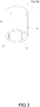
Fig. 3 shows a perspective view illustrating a modification example of a cylindrical pipe that is an impedance matching adjuster of the mixer. -
Fig. 4 shows a mixer of a third present embodiment, (a) is a front view of the partially cross section, and (b) is an X-X cross sectional view of (a). -
Fig. 5 shows the partially cross-sectional front view of a mixer of a forth present embodiment. -
Fig. 6 is the partially cross-sectional front view of the conventional mixer. - In below, embodiments of the present invention are described in details based on figures. Note that, following embodiments are essentially preferable examples, and the scope of the present invention, the application, or the use is not intended to be limited.
- The first embodiment is a
mixer 1 regarding the present invention. Themixer 1 receives a high voltage pulse from a high voltage pulse generator P (including so called "ignition coil". Same as below) and an electromagnetic wave from an electromagnetic wave oscillator MW at individual input terminals, and supplies them into an ignition device, and themixer 1 comprises an electromagneticwave input terminal 6, a high voltagepulse input terminal 5, a high voltagepulse output terminal 50, an electromagnetic waveleakage prevention structure 3 arranged between the high voltagepulse input terminal 5 and the high voltagepulse output terminal 50 and arranged in an axis similar to both the terminals, aninsulator 4 surrounding the electromagnetic waveleakage prevention structure 3 and the high voltagepulse output terminal 50, and a resonator 2 (radial resonator) formed by a cylindrical member that surrounds theinsulator 4 partially. Aninner conductor 6a of the electromagneticwave input terminal 6 is exposed toward anannular space 20 of the resonator 2 (The present embodiment includes a case where the conductor is surrounded by the insulator for the extrusion of the conductor. Same as below.), and an impedance matching adjuster 7 that attains matching between an impedance of the supplied electromagnetic wave (generally, 50Ω in a case of being supplied by a coaxial cable) and an impedance of a spark plug SP, is arranged. - The
mixer 1 is a device for supplying the high voltage pulse and the electromagnetic wave into the spark plug in order to achieve a secure ignition even through in high EGR and lean-burn by applying the high voltage pulse from the high voltage pulse generator P to be spark discharge by the spark plug SP, then generate plasma, and irradiating the electromagnetic wave, i.e., microwave to the generated plasma to be increase the plasma volume. - Then, the
mixer 1 is formed in the extrusion manner of theinner conductor 6a of the electromagneticwave input terminal 6 into theannular space 20 inside theresonator 2, and configured to supply the electromagnetic wave into the inside theresonator 2. Moreover, theimpedance matching adjuster 7 arranged at thespace 20 attains an impedance matching, the supplied electromagnetic wave is coupled to the inner conductor of the spark plug SP (generally, the center electrode of the spark plug SP), and it is configured to irradiate the electromagnetic wave from the tip end side (discharge electrode side opposing to the ground electrode) of the spark plug SP toward the inside the combustion chamber. - The
resonator 2 is divided into a part forming theannular space 20 being the supplied electromagnetic wave resonation part and a cylindrical part into which the spark plug SP is inserted. The tip end of the cylindrical part is grounded by contacting the housing part of the spark plug SP, and the supplied electromagnetic wave leakage towards outside is prevented from. - The impedance matching
adjuster 7 is, as illustrated inFig. 1 , is arranged at abottom plate 21b opposed to the electromagneticwave input terminal 6 provided at a disk-type ceiling plate 21a of theradial resonator 2 that forms the annular space 20 (in the present embodiment, theannular space 20 is formed in an annular manner), and arranged movably in upwards and downwards directions of the figure example in order to be changeable of a distance L from/to the electromagneticwave input terminal 6. Specifically, theimpedance matching adjuster 7 comprises abolt 71 engaged with a hole for screw formed at thebottom plate 21b, anut 71a for securing thebolt 71 at thebottom plate 21b, and adielectric cap 71b covering the tip end of thebolt 71. The size of thedielectric cap 71b, and the shape thereof are not specifically limited, for example, can be formed into the disk-type member having substantially equal diameter with the outer diameter of the electromagneticwave input terminal 6, in other case, also formed into a shape covering the substantially overall cross-section in a horizontal direction of the annular-type space 20, or a shape covering a cross-sectional predetermined area in the horizontal direction of thespace 20. - The impedance matching is attained by adjusting the distance L between the electromagnetic
wave input terminal 6 and the surface of thedielectric cap 71b of theimpedance matching adjuster 7, also the supplied electromagnetic wave is coupled to the high voltagepulse output terminal 50, and thereby, coupled to the inner conductor of the spark plug SP. Although the coupled electromagnetic wave is flown into the high voltagepulse input terminal 5 side, the leakage of the electromagnetic wave to the upwards than the position of the electromagnetic waveleakage prevention structure 3 is prevented from for the reason that the electromagnetic waveleakage prevention structure 3 is arranged between the high voltagepulse input terminal 5 and the high voltagepulse output terminal 50. The electromagnetic waveleakage prevention structure 3, as illustrated inFig.1 , adopts a cylindrical chock structure having a bottom part configured to open the input terminal side of the spark plug SP, and the chock depth is configured to become 1/4λ with respect to the wavelength λ of the supplied electromagnetic wave. - By adopting such a configuration, the supplied electromagnetic wave is efficiently irradiated from the tip end side of the spark plug SP (discharge electrode opposing to ground electrode) into the inside the combustion chamber.
- Moreover, the
resonator 2 thereinside forming theannular space 20, is preferably configured to become D>2×H (cylindrical outer diameter length :D, height: H) in order to be able to mount without interfering with the stay for joint to the engine frame or other device, even if the internal combustion engine has a limitation in length in the longitudinal direction. - A
mixer 1 of the present first embodiment can be reduced in length in a longitudinal direction of a resonator by adopting a resonation structure in a vertical direction (radial direction) with respect to an axis center. - In the
mixer 1 of the present second embodiment, the only different point compared to the first embodiment is the arranging position of theimpedance matching adjuster 7 and the electromagnetic waveleakage prevention structure 3, and other structures are similar to the first embodiment, and therefore, the explanation thereof is omitted. - It is configured that the electromagnetic wave
leakage prevention structure 3 surrounds the high voltagepulse output terminal 50. More specifically, the electromagnetic waveleakage prevention structure 3 adopts a choke structure having a bottom part that opens the input terminal side of the spark plug SP through the insulator arranged between the high voltagepulse output terminal 50 and the input terminal of the spark plug SP in a state where the high voltagepulse output terminal 50 is jointed to the input terminal of the spark plug SP. The choke depth is, as similar to the first embodiment, configured to become 1/4λ with respect to the wavelength λ of the supplied electromagnetic wave. - When the
resonator 2 is compared to the first embodiment, an insulator part of the spark plug SP is inserted into a part that forms theannular space 20 being a resonation part of the supplied electromagnetic wave, and the cylindrical part is configured to contact only to the housing of the spark plug (hexagonal portion for mounting to the engine head). - The impedance matching adjuster 7 of the second embodiment, as illustrated in
Fig. 2 , can become a cylindrical manner pipe 73 that is concentric to thecylindrical space 20. In the present embodiment, the length of the cylindrical manner pipe 73 becomes λ/4 wavelength with respect to the wavelength λ defined by the supplied electromagnetic wave frequency, and the cylindrical manner pipe 73 comprises a firstcylindrical pipe 73a arranged in a manner that one end thereof comes into contact with theceiling plate 21a and a secondcylindrical pipe 73b having a smaller diameter than the firstcylindrical pipe 73a and arranged in a manner that one end thereof comes into contact with thebottom plate 21b. - In this case, the
inner conductor 6a of the electromagneticwave input terminal 6 is connected to the firstcylindrical pipe 73a. A connected position of theinner conductor 6a is not especially limited; however, as illustrated, the connected position of theinner conductor 6 is preferably closer to the opening end of the firstcylindrical pipe 73a. - Then, an impedance ("Z" illustrated in below formula 1) that is defined by relative permittivity of the dielectric member that is interposed in the diameter ratio of the inner conductor of the spark plug SP, the first
cylindrical pipe 73a, and the secondcylindrical pipe 73b, is adjusted by the dielectric member that is interposed between the diameters of the firstcylindrical pipe 73a and the secondcylindrical pipe 73b so as to increase and enhance the coupling degree of the supplied electromagnetic wave in theimpedance matching adjuster 7.
- Accordingly, the impedance matching is attained by two coaxial resonators, the first
cylindrical pipe 73a and the secondcylindrical pipe 73b, and the supplied electromagnetic wave is emitted from the distal end (the discharge electrode opposed to the ground electrode) side of the spark plug SP to the inside of the combustion chamber. - Moreover, as illustrated in
Fig. 2 , theceiling plate 21a of theresonator 2 can be made as a dual structure. In this case, acylindrical pipe 21d is extended from theceiling plate 21a at the lower side so as to surround theinsulator 4, and a gap space C is provided between theupper ceiling plate 21a and the top end of thecylindrical pipe 21d. By adopting such a structure, thespace 20A sandwiched between both theceiling plates 21a functions as a choke, and the leakage of the electromagnetic wave toward the high voltagepulse input terminal 5 side, is prevented from as well as the electromagnetic waveleakage prevention structure 3. Note that, it is preferable to attain the impedance matching by filling with the dielectric member such as fluorine-based resin and PEEK material to thespace 20A. - A slit S extending in the axial direction from the opening end side toward the
ceiling plate 21a side can be formed at the circumferential surface of the firstcylindrical pipe 73a. The place and number to form the slit S are not specifically limited; however, in the present embodiment example, as illustrated in the figure, it is arranged at four places evenly on the circumferential surface. Furthermore, the slit S can also be formed at the secondcylindrical pipe 73b. - Accordingly, the coaxial resonation capacity can be reduced in size and the coupling degree with the center conductor of the spark plug SP can be enhanced by dividing the circumferential surfaces of the first
cylindrical pipe 73a and the secondcylindrical pipe 73b being theimpedance matching adjuster 7 by the slit S. - Since the
mixer 1 of the present second embodiment is configured to attain the impedance matching by two coaxial resonators, a suitable impedance matching can be attained based on the supplied electromagnetic wave. - The
mixer 1 of the present third embodiment differs from the first and second embodiments only in theimpedance matching adjuster 7, other structures are similar to the first and second embodiments, and therefore, the explanation thereof is omitted. As illustrated inFig. 4 , theimpedance matching adjuster 7 in the present third embodiment comprises ancylindrical pipe 70 coaxially with anannular space 20, acylindrical insulator 72 engaged in anotch portion 70a provided at the part facing to the connection part of thecylindrical pipe 70 with theinner conductor 6a of the electromagneticwave input terminal 6, and aconductive member 71 arranged at thecylindrical insulator 72 so as to move freely back and forth. - The
cylindrical pipe 70 is a coupling pipe so as to couple the supplied electromagnetic wave to the center conductor of the spark plug SP, and one end thereof is arranged so as to contact to thebottom plate 21b as well as the secondcylindrical pipe 73b of the second embodiment. - Further, as illustrated in
Fig. 4(b) , it is configured that the distance from the connecting point of theinner conductor 6a to thenotch portion 70a provided at the facing position becomes the distance being an integer multiple of 1/4λ with respect to the supplied-electromagnetic-wave-wavelength λ, and the connecting point of theinner conductor 6a becomes "node" point of the supplied electromagnetic wave, and the vicinity of theadjuster 7 becomes "anti-node" point of the supplied electromagnetic wave. - The
cylindrical insulator 72 that is engaged into thenotch portion 70a is not especially limited; however, in the present embodiment, the square-cylindrical-type insulator such as fluorine-based resin or PEEK material is used as illustrated, and it is configured to contact to the lowerside ceiling plate 21a. - Further, the
conductive member 71 that moves forth and back into the hole of theannular insulator 72 is not especially limited in member; however, a bolt secured via thenut 71a to theceiling plate 21a at the upper side is used. - When the
bottom surface 71c of the bolt being theconductive member 71 is positioned at the above of the top end surface of the cylindrical pipe 70 (as illustrated by two-dot chain line in the figure example), theimpedance matching adjuster 7 forms a capacitor between the top end surface of thecylindrical pipe 70 and theconductive member 71, and it functions as a stub when thebottom surface 71c is positioned at the below of the top end surface of thecylindrical pipe 70. - The supplied electromagnetic wave is efficiently irradiated from the tip end (discharge electrode opposed to the ground electrode) side of the spark plug SP toward the inside of the combustion chamber by attaining the impedance matching in such a structure.
- In the
mixer 1 of the present embodiment, the impedance matching adjuster is constituted by the annular insulator being engaged in the notch portion provided at the facing position to the part connected of the inner conductor of the electromagnetic wave input terminal of the cylindrical pipe that constitutes the coaxial resonator and the conductive member arranged at the annular insulator in freely-moving-forth-and-back manner. Further, the pseudo capacitor and the stub are formed based on the position of the conductive member being arranged, and therefore, the inputted electromagnetic wave impedance can be adjusted minutely. - The
mixer 1 of the fourth present embodiment, as illustrated inFig. 5 , comprises the high-voltage-pulse-input-terminal 5, the high-voltage-pulse-output-terminal 50, the electromagnetic waveleakage prevention structure 3, and theinsulator 40 that surrounds them, so as to attach and detach freely. Theimpedance matching adjuster 7, as similar to the second embodiment, can become the cylindrical pipe 73 coaxially with thecylindrical space 20. The length of the cylindrical pipe 73 becomes in length of λ/4 with respect to the wavelength λ defined by the supplied electromagnetic wave frequency, and the cylindrical pipe 73 comprises the firstcylindrical pipe 73a that is arranged so as to contact to theceiling plate 21a at one end thereof, and the secondcylindrical pipe 73b in smaller diameter than the firstcylindrical pipe 73a and arranged so as to contact to thebottom plate 21b at one end thereof; however, it is not limited to the above, and the structure similar to the first embodiment and the second embodiment may be adopted. - The
insulator 40 connects electrically the high-voltage-input-terminal 5 for receiving the supply of the high voltage pulse from the high voltage pulse generator P to the high-voltage-output-terminal 50 configured to supply the high voltage pulse into the input terminal of the spark plug SP. Then, the electromagnetic waveleakage prevention structure 3 is configured to surround the high-voltage-pulse-output-terminal 50 as well as the second embodiment. In below, these are collectively together referred to "inputterminal 9." - With regard to the center of the
space 20, a hole is formed respectively in the center of theceiling plate 21a and the center of thebottom plate 21b in order that the spark plug SP and theinput terminal 9 can be inserted therethrough. As a result, engaged into the hole of the insulator 40(4) of theinput terminal 9. Theinsulator 4 that surrounds the high-voltage-pulse-output-terminal 50 and the electromagnetic waveleakage prevention structure 3, is configured to become somewhat larger in diameter than the hole part, and the material thereof may preferably be a flexible one. The insulator 41 (4) is arranged between the secondcylindrical pipe 73b and theinput terminal 9 at thespace 20. The material of theinsulator 41 can be selected as one among kinds of materials such as PEEK material, fluorine-based resin, aluminum, and silicon nitride. The material having the suitable dielectric permittivity is selected in accordance to the supplied electromagnetic wave frequency and etc., and the fine technical adjustment and fitting of theimpedance matching adjuster 7 can be performed. - The
input terminal 9 provides with a spring inside the conductive path, and the connection to the spark plug SP can be supported. Moreover, an engaging ring being eccentric to the axis center and moving toward the direction perpendicular to the axis center, is arranged at the high-voltage-pulse-output-terminal 50 so as to engage to a step portion of the input terminal of the spark plug SP. Moreover, the high-voltage-pulse-input-terminal 5 is configured to be perpendicular to the axis center of the spark plug SP; however, not limited to this. - The
mixer 1 of the present forth embodiment comprises theresonator 2 part and theinput terminal 9 part including the high-voltage-pulse-input-terminal 5, the high-voltage-pulse-output-terminal 50, the electromagnetic waveleakage prevention structure 3 and theinsulator 40 surrounding them, and therefore, a cost reduction can be achieved by changing a portion of theinput terminal 9 into a cord for the spark plug improved at the distal end. - As illustrated above, the mixer of the present invention can suitably be used in not only the general internal combustion engine but also in the internal combustion engine in a case of less allowance in the engine outline surrounding.
-
- 1.
- Mixer
- 2.
- Resonator
- 20.
- Space
- 3.
- Electromagnetic Wave Leakage Prevention Structure
- 4.
- Insulator
- 5.
- High Voltage Pulse Input Terminal
- 50.
- High Voltage Pulse Output Terminal
- 6.
- Electromagnetic Wave Input Terminal
- 7.
- Impedance Matching Adjuster
- 70.
- Cylindrical Pipe
- 73.
- Cylindrical Pipe
- 73a.
- First Cylindrical Pipe
- 73b.
- Second Cylindrical Pipe
- P
- High Voltage Pulse Generator
- MW
- Electromagnetic Wave Oscillator
- SP
- Spark Plug
Claims (4)
- A mixer for receiving a high voltage pulse from a high voltage pulse generator and an electromagnetic wave from an electromagnetic wave oscillator via individual input terminals and supplying the high voltage pulse and the electromagnetic wave into an ignition device, the mixer comprising:an electromagnetic wave input terminal configured to receive the electromagnetic wave from the electromagnetic wave oscillator;a high voltage pulse input terminal provided separately from the electromagnetic wave input terminal and configured to receive the high voltage pulse from the high voltage pulse generator;a high voltage pulse output terminal configured to output the electromagnetic wave and the high voltage pulse to the ignition device;an electromagnetic wave leakage prevention structure arranged between the high voltage pulse input terminal and the high voltage pulse output terminal;an insulator surrounding the electromagnetic wave leakage prevention structure and the high voltage pulse output terminal; anda cylindrical conductive member surrounding a part of the insulator,wherein the cylindrical conductive member forms a resonator connected to the electromagnetic wave input terminal, andwherein an impedance matching adjuster is arranged inside the resonator.
- The mixer according to claim 1,
wherein the impedance matching adjuster comprises a conductor having a length which is changeable in at least one direction of an axial direction and a direction perpendicular to the axial direction inside the resonator. - The mixer according to claim 1 or claim 2,
wherein the electromagnetic wave leakage prevention structure comprises a cylindrical member surrounding the high voltage pulse output terminal. - The mixer according to any one of claims 1 to 3,
wherein each of the high voltage pulse input terminal, the high voltage pulse output terminal, the electromagnetic wave leakage prevention structure, and the insulator surrounding them is configured to be detachable from and attachable to the mixer.
Applications Claiming Priority (2)
| Application Number | Priority Date | Filing Date | Title |
|---|---|---|---|
| JP2015156406 | 2015-08-06 | ||
| PCT/JP2016/073084 WO2017022849A1 (en) | 2015-08-06 | 2016-08-05 | Mixer |
Publications (1)
| Publication Number | Publication Date |
|---|---|
| EP3333414A1 true EP3333414A1 (en) | 2018-06-13 |
Family
ID=57943497
Family Applications (1)
| Application Number | Title | Priority Date | Filing Date |
|---|---|---|---|
| EP16833128.8A Withdrawn EP3333414A1 (en) | 2015-08-06 | 2016-08-05 | Mixer |
Country Status (4)
| Country | Link |
|---|---|
| US (1) | US20190010911A1 (en) |
| EP (1) | EP3333414A1 (en) |
| JP (1) | JPWO2017022849A1 (en) |
| WO (1) | WO2017022849A1 (en) |
Families Citing this family (1)
| Publication number | Priority date | Publication date | Assignee | Title |
|---|---|---|---|---|
| JP6963928B2 (en) * | 2017-07-27 | 2021-11-10 | マツダ株式会社 | Spark plug mounting structure, mounting jig and spark plug mounting method |
Family Cites Families (2)
| Publication number | Priority date | Publication date | Assignee | Title |
|---|---|---|---|---|
| US8861173B2 (en) * | 2009-08-06 | 2014-10-14 | Imagineering, Inc. | Mixer, matching device, ignition unit, and plasma generator |
| WO2014203873A1 (en) * | 2013-06-18 | 2014-12-24 | イマジニアリング株式会社 | Ignition plug and plasma generation device |
-
2016
- 2016-08-05 EP EP16833128.8A patent/EP3333414A1/en not_active Withdrawn
- 2016-08-05 WO PCT/JP2016/073084 patent/WO2017022849A1/en not_active Ceased
- 2016-08-05 US US15/750,552 patent/US20190010911A1/en not_active Abandoned
- 2016-08-05 JP JP2017533134A patent/JPWO2017022849A1/en active Pending
Also Published As
| Publication number | Publication date |
|---|---|
| US20190010911A1 (en) | 2019-01-10 |
| JPWO2017022849A1 (en) | 2018-06-07 |
| WO2017022849A1 (en) | 2017-02-09 |
Similar Documents
| Publication | Publication Date | Title |
|---|---|---|
| CN102472240B (en) | Mixer, matching device, ignition unit, and plasma generator | |
| US9624898B2 (en) | Compact electromagnetic plasma ignition device | |
| US9873315B2 (en) | Dual signal coaxial cavity resonator plasma generation | |
| US8464679B2 (en) | Corona tip insulator | |
| KR102083337B1 (en) | High voltage connection sealing method for corona ignition coil | |
| JP2014501431A (en) | Corona igniter with asymmetric ignition | |
| EP3037651A1 (en) | Ignition system for internal combustion engine, and internal combustion engine | |
| RU2577319C2 (en) | Ice spark-plug | |
| KR20130139893A (en) | Corona igniter having shaped insulator | |
| US7233084B2 (en) | Microwave generator | |
| EP3333414A1 (en) | Mixer | |
| CN103967684B (en) | corona ignition device | |
| WO2016084772A1 (en) | Ignition unit, ignition system, and internal combustion engine | |
| WO2017065310A1 (en) | Ignition device | |
| RU2419960C2 (en) | Microwave generator | |
| US7400484B2 (en) | Coaxial overvoltage protector | |
| WO2016108283A1 (en) | Ignition system, and internal combustion engine | |
| JPWO2016125857A1 (en) | Spark plug | |
| HK1234469A1 (en) | Dual signal coaxial cavity resonator plasma generation | |
| JP2022511889A (en) | Ignition system and prime mover products | |
| JP5858536B2 (en) | Ignition system |
Legal Events
| Date | Code | Title | Description |
|---|---|---|---|
| STAA | Information on the status of an ep patent application or granted ep patent |
Free format text: STATUS: THE INTERNATIONAL PUBLICATION HAS BEEN MADE |
|
| PUAI | Public reference made under article 153(3) epc to a published international application that has entered the european phase |
Free format text: ORIGINAL CODE: 0009012 |
|
| STAA | Information on the status of an ep patent application or granted ep patent |
Free format text: STATUS: REQUEST FOR EXAMINATION WAS MADE |
|
| 17P | Request for examination filed |
Effective date: 20180305 |
|
| AK | Designated contracting states |
Kind code of ref document: A1 Designated state(s): AL AT BE BG CH CY CZ DE DK EE ES FI FR GB GR HR HU IE IS IT LI LT LU LV MC MK MT NL NO PL PT RO RS SE SI SK SM TR |
|
| AX | Request for extension of the european patent |
Extension state: BA ME |
|
| DAV | Request for validation of the european patent (deleted) | ||
| DAX | Request for extension of the european patent (deleted) | ||
| STAA | Information on the status of an ep patent application or granted ep patent |
Free format text: STATUS: THE APPLICATION IS DEEMED TO BE WITHDRAWN |
|
| 18D | Application deemed to be withdrawn |
Effective date: 20190301 |