EP3333375A1 - Sync ring assembly and associated clevis including a rib - Google Patents
Sync ring assembly and associated clevis including a rib Download PDFInfo
- Publication number
- EP3333375A1 EP3333375A1 EP17205661.6A EP17205661A EP3333375A1 EP 3333375 A1 EP3333375 A1 EP 3333375A1 EP 17205661 A EP17205661 A EP 17205661A EP 3333375 A1 EP3333375 A1 EP 3333375A1
- Authority
- EP
- European Patent Office
- Prior art keywords
- clevis
- sync ring
- rib
- ring assembly
- sync
- Prior art date
- Legal status (The legal status is an assumption and is not a legal conclusion. Google has not performed a legal analysis and makes no representation as to the accuracy of the status listed.)
- Granted
Links
Images





Classifications
-
- F—MECHANICAL ENGINEERING; LIGHTING; HEATING; WEAPONS; BLASTING
- F01—MACHINES OR ENGINES IN GENERAL; ENGINE PLANTS IN GENERAL; STEAM ENGINES
- F01D—NON-POSITIVE DISPLACEMENT MACHINES OR ENGINES, e.g. STEAM TURBINES
- F01D25/00—Component parts, details, or accessories, not provided for in, or of interest apart from, other groups
- F01D25/04—Antivibration arrangements
-
- F—MECHANICAL ENGINEERING; LIGHTING; HEATING; WEAPONS; BLASTING
- F01—MACHINES OR ENGINES IN GENERAL; ENGINE PLANTS IN GENERAL; STEAM ENGINES
- F01D—NON-POSITIVE DISPLACEMENT MACHINES OR ENGINES, e.g. STEAM TURBINES
- F01D17/00—Regulating or controlling by varying flow
- F01D17/10—Final actuators
- F01D17/12—Final actuators arranged in stator parts
- F01D17/14—Final actuators arranged in stator parts varying effective cross-sectional area of nozzles or guide conduits
- F01D17/16—Final actuators arranged in stator parts varying effective cross-sectional area of nozzles or guide conduits by means of nozzle vanes
-
- F—MECHANICAL ENGINEERING; LIGHTING; HEATING; WEAPONS; BLASTING
- F01—MACHINES OR ENGINES IN GENERAL; ENGINE PLANTS IN GENERAL; STEAM ENGINES
- F01D—NON-POSITIVE DISPLACEMENT MACHINES OR ENGINES, e.g. STEAM TURBINES
- F01D17/00—Regulating or controlling by varying flow
- F01D17/10—Final actuators
- F01D17/12—Final actuators arranged in stator parts
- F01D17/14—Final actuators arranged in stator parts varying effective cross-sectional area of nozzles or guide conduits
- F01D17/16—Final actuators arranged in stator parts varying effective cross-sectional area of nozzles or guide conduits by means of nozzle vanes
- F01D17/162—Final actuators arranged in stator parts varying effective cross-sectional area of nozzles or guide conduits by means of nozzle vanes for axial flow, i.e. the vanes turning around axes which are essentially perpendicular to the rotor centre line
-
- F—MECHANICAL ENGINEERING; LIGHTING; HEATING; WEAPONS; BLASTING
- F01—MACHINES OR ENGINES IN GENERAL; ENGINE PLANTS IN GENERAL; STEAM ENGINES
- F01D—NON-POSITIVE DISPLACEMENT MACHINES OR ENGINES, e.g. STEAM TURBINES
- F01D25/00—Component parts, details, or accessories, not provided for in, or of interest apart from, other groups
- F01D25/24—Casings; Casing parts, e.g. diaphragms, casing fastenings
- F01D25/243—Flange connections; Bolting arrangements
-
- F—MECHANICAL ENGINEERING; LIGHTING; HEATING; WEAPONS; BLASTING
- F04—POSITIVE - DISPLACEMENT MACHINES FOR LIQUIDS; PUMPS FOR LIQUIDS OR ELASTIC FLUIDS
- F04D—NON-POSITIVE-DISPLACEMENT PUMPS
- F04D29/00—Details, component parts, or accessories
- F04D29/40—Casings; Connections of working fluid
- F04D29/52—Casings; Connections of working fluid for axial pumps
- F04D29/522—Casings; Connections of working fluid for axial pumps especially adapted for elastic fluid pumps
-
- F—MECHANICAL ENGINEERING; LIGHTING; HEATING; WEAPONS; BLASTING
- F04—POSITIVE - DISPLACEMENT MACHINES FOR LIQUIDS; PUMPS FOR LIQUIDS OR ELASTIC FLUIDS
- F04D—NON-POSITIVE-DISPLACEMENT PUMPS
- F04D29/00—Details, component parts, or accessories
- F04D29/40—Casings; Connections of working fluid
- F04D29/52—Casings; Connections of working fluid for axial pumps
- F04D29/54—Fluid-guiding means, e.g. diffusers
- F04D29/56—Fluid-guiding means, e.g. diffusers adjustable
- F04D29/563—Fluid-guiding means, e.g. diffusers adjustable specially adapted for elastic fluid pumps
-
- F—MECHANICAL ENGINEERING; LIGHTING; HEATING; WEAPONS; BLASTING
- F05—INDEXING SCHEMES RELATING TO ENGINES OR PUMPS IN VARIOUS SUBCLASSES OF CLASSES F01-F04
- F05D—INDEXING SCHEME FOR ASPECTS RELATING TO NON-POSITIVE-DISPLACEMENT MACHINES OR ENGINES, GAS-TURBINES OR JET-PROPULSION PLANTS
- F05D2220/00—Application
- F05D2220/30—Application in turbines
- F05D2220/32—Application in turbines in gas turbines
-
- F—MECHANICAL ENGINEERING; LIGHTING; HEATING; WEAPONS; BLASTING
- F05—INDEXING SCHEMES RELATING TO ENGINES OR PUMPS IN VARIOUS SUBCLASSES OF CLASSES F01-F04
- F05D—INDEXING SCHEME FOR ASPECTS RELATING TO NON-POSITIVE-DISPLACEMENT MACHINES OR ENGINES, GAS-TURBINES OR JET-PROPULSION PLANTS
- F05D2260/00—Function
- F05D2260/50—Kinematic linkage, i.e. transmission of position
-
- F—MECHANICAL ENGINEERING; LIGHTING; HEATING; WEAPONS; BLASTING
- F05—INDEXING SCHEMES RELATING TO ENGINES OR PUMPS IN VARIOUS SUBCLASSES OF CLASSES F01-F04
- F05D—INDEXING SCHEME FOR ASPECTS RELATING TO NON-POSITIVE-DISPLACEMENT MACHINES OR ENGINES, GAS-TURBINES OR JET-PROPULSION PLANTS
- F05D2260/00—Function
- F05D2260/70—Adjusting of angle of incidence or attack of rotating blades
- F05D2260/79—Bearing, support or actuation arrangements therefor
-
- F—MECHANICAL ENGINEERING; LIGHTING; HEATING; WEAPONS; BLASTING
- F05—INDEXING SCHEMES RELATING TO ENGINES OR PUMPS IN VARIOUS SUBCLASSES OF CLASSES F01-F04
- F05D—INDEXING SCHEME FOR ASPECTS RELATING TO NON-POSITIVE-DISPLACEMENT MACHINES OR ENGINES, GAS-TURBINES OR JET-PROPULSION PLANTS
- F05D2260/00—Function
- F05D2260/96—Preventing, counteracting or reducing vibration or noise
-
- F—MECHANICAL ENGINEERING; LIGHTING; HEATING; WEAPONS; BLASTING
- F05—INDEXING SCHEMES RELATING TO ENGINES OR PUMPS IN VARIOUS SUBCLASSES OF CLASSES F01-F04
- F05D—INDEXING SCHEME FOR ASPECTS RELATING TO NON-POSITIVE-DISPLACEMENT MACHINES OR ENGINES, GAS-TURBINES OR JET-PROPULSION PLANTS
- F05D2300/00—Materials; Properties thereof
- F05D2300/10—Metals, alloys or intermetallic compounds
- F05D2300/13—Refractory metals, i.e. Ti, V, Cr, Zr, Nb, Mo, Hf, Ta, W
- F05D2300/133—Titanium
-
- Y—GENERAL TAGGING OF NEW TECHNOLOGICAL DEVELOPMENTS; GENERAL TAGGING OF CROSS-SECTIONAL TECHNOLOGIES SPANNING OVER SEVERAL SECTIONS OF THE IPC; TECHNICAL SUBJECTS COVERED BY FORMER USPC CROSS-REFERENCE ART COLLECTIONS [XRACs] AND DIGESTS
- Y02—TECHNOLOGIES OR APPLICATIONS FOR MITIGATION OR ADAPTATION AGAINST CLIMATE CHANGE
- Y02T—CLIMATE CHANGE MITIGATION TECHNOLOGIES RELATED TO TRANSPORTATION
- Y02T50/00—Aeronautics or air transport
- Y02T50/60—Efficient propulsion technologies, e.g. for aircraft
Definitions
- Gas turbine engines such as those which power aircraft and industrial equipment, employ a compressor to compress air that is drawn into the engine and a turbine to capture energy associated with the combustion of a fuel-air mixture.
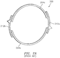
- the assembly 200 is formed from sync rings 204a and 204b.
- the sync rings 204a and 204b are coupled to one another via clevises 212a and 212b.
- the sync rings 204a and 204b are made of steel and the clevises 212a and 212b are made of nickel.
- FIG. 2B illustrates a clevis (e.g., clevis 212a) of the assembly 200 of FIG. 2A .
- the clevis incudes stand-offs 222a, 222b, and 222c at/proximate a first end 224 of the clevis.
- the stand-offs include holes to seat fasteners (not shown) for coupling the clevis to a sync ring (e.g., sync ring 204a - see FIG. 2A ).
- the clevis also includes a wall 232 in proximity to the stand-offs 222a-222c.
- FIG. 2C illustrates a cross-section of the clevis of FIG. 2B taken about the line 252a-252b. The reasons for the inclusion of FIG. 2C will become more apparent in the description to follow.
- the assembly 200 may experience one or more deflections during a surge condition (where the surge condition may be in response to one or more changing environmental conditions, operator/pilot inputs, etc.).
- the assembly 200 may be required to provide an associated degree of stiffness to counter/resist the tendency to deflect during the surge condition.
- sync ring assembly that has greater stiffness to reduce the magnitude of the deflections experienced by the sync ring assembly during engine operation. Furthermore, a reduction in weight of the sync ring assembly would promote engine efficiency/performance in terms of, e.g., thrust specific fuel consumption.
- a sync ring assembly associated with an engine comprising: a sync ring, and a clevis coupled to the sync ring, where the clevis includes a rib that resists a deflection of the sync ring assembly when the engine is operated, and where the clevis is made of titanium.
- the rib is located on an interior of the clevis.
- the clevis includes a second rib.
- the second rib is located on an exterior of the clevis.
- the rib is located on an exterior of the clevis.
- the clevis includes at least one stand-off that includes a hole to seat a fastener that couples the clevis to the sync ring. In some embodiments, a radial projection of the rib is confined within a radial projection of the at least one stand-off. In some embodiments, the at least one stand-off is located proximate a first end of the clevis. In some embodiments, the clevis is wall-free in proximity to a first end of the clevis. In some embodiments, the clevis includes a wall proximate to a second end of the clevis, where the second end is opposed to the first end.
- the sync ring assembly further comprises a second clevis coupled to the sync ring. In some embodiments, the sync ring assembly further comprises a second sync ring coupled to the first clevis and the second clevis. In some embodiments, the second clevis includes a second rib.
- connections are set forth between elements in the following description and in the drawings (the contents of which are included in this disclosure by way of reference). It is noted that these connections are general and, unless specified otherwise, may be direct or indirect and that this specification is not intended to be limiting in this respect.
- a coupling between two or more entities may refer to a direct connection or an indirect connection.
- An indirect connection may incorporate one or more intervening entities or a space/gap between the entities that are being coupled to one another.
- the sync ring assembly may include one or more sync rings and one or more clevises.
- a clevis may be manufactured of one or more materials, e.g., titanium.
- the clevis may include a rib that may provide stiffness to the clevis.
- FIG. 1 is a side cutaway illustration of a geared turbine engine 10.
- This turbine engine 10 extends along an axial centerline 12 between an upstream airflow inlet 14 and a downstream airflow exhaust 16.
- the turbine engine 10 includes a fan section 18, a compressor section 19, a combustor section 20 and a turbine section 21.
- the compressor section 19 includes a low pressure compressor (LPC) section 19A and a high pressure compressor (HPC) section 19B.
- the turbine section 21 includes a high pressure turbine (HPT) section 21A and a low pressure turbine (LPT) section 21B.
- the engine sections 18-21 are arranged sequentially along the centerline 12 within an engine housing 22.
- Each of the engine sections 18-19B, 21A and 21B includes a respective rotor 24-28.
- Each of these rotors 24-28 includes a plurality of rotor blades arranged circumferentially around and connected to one or more respective rotor disks.
- the rotor blades may be formed integral with or mechanically fastened, welded, brazed, adhered and/or otherwise attached to the respective rotor disk(s).
- the fan rotor 24 is connected to a gear train 30, for example, through a fan shaft 32.
- the gear train 30 and the LPC rotor 25 are connected to and driven by the LPT rotor 28 through a low speed shaft 33.
- the HPC rotor 26 is connected to and driven by the HPT rotor 27 through a high speed shaft 34.
- the shafts 32-34 are rotatably supported by a plurality of bearings 36; e.g., rolling element and/or thrust bearings. Each of these bearings 36 is connected to the engine housing 22 by at least one stationary structure such as, for example, an annular support strut.
- the air within the core gas path 38 may be referred to as "core air”.
- the air within the bypass gas path 40 may be referred to as "bypass air”.
- the core air is directed through the engine sections 19-21, and exits the turbine engine 10 through the airflow exhaust 16 to provide forward engine thrust.
- fuel is injected into a combustion chamber 42 and mixed with compressed core air. This fuel-core air mixture is ignited to power the turbine engine 10.
- the bypass air is directed through the bypass gas path 40 and out of the turbine engine 10 through a bypass nozzle 44 to provide additional forward engine thrust. This additional forward engine thrust may account for a majority (e.g., more than 70 percent) of total engine thrust.
- at least some of the bypass air may be directed out of the turbine engine 10 through a thrust reverser to provide reverse engine thrust.
- FIG. 1 represents one possible configuration for an engine 10. Aspects of the disclosure may be applied in connection with other environments, including additional configurations for gas turbine engines.
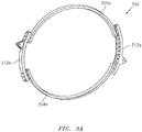
- a sync ring assembly 300 is shown.
- the assembly 300 may be formed from sync rings 304a and 304b.
- the sync rings 304a and 304b may correspond to the sync rings 204a and 204b, respectively (see FIG. 2A ).
- the sync rings 304a and 304b may be coupled to one another via clevises 312a and 312b.
- the clevises 312a and 312b may be manufactured of one or more materials.
- the clevises 312a and 312b may be manufactured by "hogging-out" titanium.
- Other techniques may be used in the manufacture of the clevises 312a and 312b. For example, casting, forging, etc., may be used in some embodiments.
- the assembly 300 may be incorporated as part of/over split case flanges of an engine (e.g., the engine 10 of FIG. 1 ).
- the flanges may be associated with the compressor section of the engine (e.g., compressor section 19 of FIG. 1 ).
- FIG. 4 illustrates a plurality of clevises 312-1, 312-2, 312-3, and 312-4 (where the clevises 312-1 through 312-4 may correspond to the clevis 312a or the clevis 312b of FIG. 3A ).
- the clevises 312-1 through 312-4 are shown as being arranged in one or more axial stages/station planes.
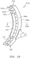
- FIG. 3B illustrates the clevis 312a of the assembly 300 of FIG. 3A . While a description of various features of the clevis 312a is provided below, the clevis 312b may include analogous/corresponding features. In this respect, a complete re-description of such features is omitted herein for the sake of brevity.
- the clevis 312a may include stand-offs 322a, 322b, and 322c at/proximate a first end 324 of the clevis.
- the stand-offs 322a-322c may include holes to seat fasteners (not shown) for coupling the clevis to a sync ring (e.g., sync ring 304a - see FIG. 3A ).
- a sync ring e.g., sync ring 304a - see FIG. 3A .
- FIG. 2B unlike the inclusion of the wall 232 in proximity to the stand-offs 222a-222c shown in FIG. 2B , in FIG.
- such a wall might not be present in proximity to the stand-offs 322a-322c, which is to say that the clevis may be "wall-free" in proximity to the stand-offs 322a-322c or the first end 324.
- the lack of such a wall in FIG. 3B may help to reduce the weight of the clevis of FIG. 3B (relative to the clevis of FIG. 2B ).
- the clevises 312a and 312b may be manufactured to include a rib.
- a rib 362 may be included with the clevis 312a.
- the particular size/dimension, weight, and/or profile of the rib 362 may be selected to provide at least the same level/degree of stiffness/resistance to deflections for the assembly 300 (see FIG. 3A ) as the assembly 200 (see FIG. 2A ).
- a radial projection of the rib 362 may not exceed (e.g., may be confined within) a radial projection/span of the stand-offs 322a-322c.
- the clevises 312a and 312b may be backwards compatible with existing/conventional clevises (e.g., clevises 212a and 212b of FIGS. 2A-2B ). Such backwards compatibility may be useful for retrofitting/substituting the clevises 312a and 312b for existing hardware/assemblies that may already be in-service/in-the-field.
- rib 362 is shown in FIG. 3B as being located on the interior/inner diameter 366a of the clevis 312a, the rib may be located on the exterior/outer diameter 366b of the clevis 312a in some embodiments. In some embodiments, a first rib may be located on the interior/inner diameter 366a and a second rib may be located on the exterior/outer diameter 366b of the clevis 312a.
- locating that rib on the interior/inner diameter 366a of the clevis 312a may provide greater stiffness to the assembly 300 (see FIG. 3A ) than locating the rib on the exterior/outer diameter 366b.
- stiffness per unit mass or per unit of dimension of the rib
- there might not be sufficient space available on the exterior/outer diameter 366b of the clevis 312a due to other components/parts of an engine that may be located in proximity to the clevis 312a when the assembly 300 is installed on the engine.
- a wall 372 At/proximate a second end 326 of the clevis 312a (where the second end 326 is opposed to the first end 324) there may be a wall 372.
- the wall 372, in combination with the rib 362 located between the ends 324 and 326, may provide for a mistake-proof assembly of the clevis 312a with respect to the rest of the assembly 300 (see FIG. 3A ).
- the combination of the wall 372 and the rib 362 may prevent the clevis 312a from being installed in an inverted direction (e.g., the end 326 at the top and the end 324 at the bottom) relative to what is shown in FIG. 3B .
- the clevis 312a may include one or more features to ensure that the clevis 312 is installed/assembled in accordance with a predetermined orientation.
- FIG. 3C illustrates a cross-section of the clevis of FIG. 3B taken about the line 352a-352b.
- the portion denoted by/within the dashed circle 362' is attributable to the presence of the rib 362 (see FIG. 3B ) that is lacking/absent in FIG. 2B .
Landscapes
- Engineering & Computer Science (AREA)
- Mechanical Engineering (AREA)
- General Engineering & Computer Science (AREA)
- Structures Of Non-Positive Displacement Pumps (AREA)
Abstract
Description
- Gas turbine engines, such as those which power aircraft and industrial equipment, employ a compressor to compress air that is drawn into the engine and a turbine to capture energy associated with the combustion of a fuel-air mixture.
- Referring to
FIG. 2A , a prior artsync ring assembly 200 is shown. Theassembly 200 is formed fromsync rings sync rings clevises sync rings clevises -
FIG. 2B illustrates a clevis (e.g.,clevis 212a) of theassembly 200 ofFIG. 2A . As shown, the clevis incudes stand-offs first end 224 of the clevis. The stand-offs include holes to seat fasteners (not shown) for coupling the clevis to a sync ring (e.g.,sync ring 204a - seeFIG. 2A ). The clevis also includes awall 232 in proximity to the stand-offs 222a-222c.FIG. 2C illustrates a cross-section of the clevis ofFIG. 2B taken about theline 252a-252b. The reasons for the inclusion ofFIG. 2C will become more apparent in the description to follow. - During engine operation, the
assembly 200 may experience one or more deflections during a surge condition (where the surge condition may be in response to one or more changing environmental conditions, operator/pilot inputs, etc.). In order to maintain the structural and functionality integrity of the engine, theassembly 200 may be required to provide an associated degree of stiffness to counter/resist the tendency to deflect during the surge condition. - Accordingly, what is needed is a sync ring assembly that has greater stiffness to reduce the magnitude of the deflections experienced by the sync ring assembly during engine operation. Furthermore, a reduction in weight of the sync ring assembly would promote engine efficiency/performance in terms of, e.g., thrust specific fuel consumption.
- The following presents a simplified summary in order to provide a basic understanding of some aspects of the disclosure. The summary is not an extensive overview of the disclosure. It is neither intended to identify key or critical elements of the disclosure nor to delineate the scope of the disclosure. The following summary merely presents some concepts of the disclosure in a simplified form as a prelude to the description below.
- Aspects of the disclosure are directed to a sync ring assembly associated with an engine, comprising: a sync ring, and a clevis coupled to the sync ring, where the clevis includes a rib that resists a deflection of the sync ring assembly when the engine is operated, and where the clevis is made of titanium. In some embodiments, the rib is located on an interior of the clevis. In some embodiments, the clevis includes a second rib. In some embodiments, the second rib is located on an exterior of the clevis. In some embodiments, the rib is located on an exterior of the clevis. In some embodiments, the clevis includes at least one stand-off that includes a hole to seat a fastener that couples the clevis to the sync ring. In some embodiments, a radial projection of the rib is confined within a radial projection of the at least one stand-off. In some embodiments, the at least one stand-off is located proximate a first end of the clevis. In some embodiments, the clevis is wall-free in proximity to a first end of the clevis. In some embodiments, the clevis includes a wall proximate to a second end of the clevis, where the second end is opposed to the first end. In some embodiments, the sync ring assembly further comprises a second clevis coupled to the sync ring. In some embodiments, the sync ring assembly further comprises a second sync ring coupled to the first clevis and the second clevis. In some embodiments, the second clevis includes a second rib.
- The present disclosure is illustrated by way of example and not limited in the accompanying figures in which like reference numerals indicate similar elements. The drawing figures are not necessarily drawn to scale unless specifically indicated otherwise.
-
FIG. 1 is a side cutaway illustration of a geared turbine engine. -
FIG. 2A illustrates a prior art sync ring assembly. -
FIG. 2B illustrates a clevis of the sync ring assembly ofFIG. 2A . -
FIG. 2C illustrates a cross-section of the clevis ofFIG. 2B . -
FIG. 3A illustrates a sync ring assembly in accordance with aspects of this disclosure. -
FIG. 3B illustrates a clevis of the sync ring assembly ofFIG. 3A . -
FIG. 3C illustrates a cross-section of the clevis ofFIG. 3B . -
FIG. 4 illustrates an arrangement of clevises in a plurality of stages. -
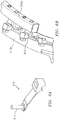
FIG. 5A illustrates a fastener in accordance with the prior art. -
FIG. 5B illustrates a coupling of a sync ring and a clevis using the fastener ofFIG. 5A . -
FIG. 6A illustrates a fastener in accordance with aspects of this disclosure. -
FIG. 6B illustrates a coupling of a sync ring and a clevis using the fastener ofFIG. 6A . - It is noted that various connections are set forth between elements in the following description and in the drawings (the contents of which are included in this disclosure by way of reference). It is noted that these connections are general and, unless specified otherwise, may be direct or indirect and that this specification is not intended to be limiting in this respect. A coupling between two or more entities may refer to a direct connection or an indirect connection. An indirect connection may incorporate one or more intervening entities or a space/gap between the entities that are being coupled to one another.
- Aspects of the disclosure are directed to apparatuses, systems, and method associated with a sync ring assembly for an engine. The sync ring assembly may include one or more sync rings and one or more clevises. A clevis may be manufactured of one or more materials, e.g., titanium. The clevis may include a rib that may provide stiffness to the clevis.
- Aspects of the disclosure may be applied in connection with a gas turbine engine.
FIG. 1 is a side cutaway illustration of a gearedturbine engine 10. Thisturbine engine 10 extends along anaxial centerline 12 between anupstream airflow inlet 14 and adownstream airflow exhaust 16. Theturbine engine 10 includes afan section 18, acompressor section 19, acombustor section 20 and aturbine section 21. Thecompressor section 19 includes a low pressure compressor (LPC)section 19A and a high pressure compressor (HPC)section 19B. Theturbine section 21 includes a high pressure turbine (HPT)section 21A and a low pressure turbine (LPT)section 21B. - The engine sections 18-21 are arranged sequentially along the
centerline 12 within anengine housing 22. Each of the engine sections 18-19B, 21A and 21B includes a respective rotor 24-28. Each of these rotors 24-28 includes a plurality of rotor blades arranged circumferentially around and connected to one or more respective rotor disks. The rotor blades, for example, may be formed integral with or mechanically fastened, welded, brazed, adhered and/or otherwise attached to the respective rotor disk(s). - The
fan rotor 24 is connected to agear train 30, for example, through afan shaft 32. Thegear train 30 and theLPC rotor 25 are connected to and driven by theLPT rotor 28 through alow speed shaft 33. TheHPC rotor 26 is connected to and driven by theHPT rotor 27 through ahigh speed shaft 34. The shafts 32-34 are rotatably supported by a plurality ofbearings 36; e.g., rolling element and/or thrust bearings. Each of thesebearings 36 is connected to theengine housing 22 by at least one stationary structure such as, for example, an annular support strut. - During operation, air enters the
turbine engine 10 through theairflow inlet 14, and is directed through thefan section 18 and into acore gas path 38 and abypass gas path 40. The air within thecore gas path 38 may be referred to as "core air". The air within thebypass gas path 40 may be referred to as "bypass air". The core air is directed through the engine sections 19-21, and exits theturbine engine 10 through theairflow exhaust 16 to provide forward engine thrust. Within thecombustor section 20, fuel is injected into acombustion chamber 42 and mixed with compressed core air. This fuel-core air mixture is ignited to power theturbine engine 10. The bypass air is directed through thebypass gas path 40 and out of theturbine engine 10 through abypass nozzle 44 to provide additional forward engine thrust. This additional forward engine thrust may account for a majority (e.g., more than 70 percent) of total engine thrust. Alternatively, at least some of the bypass air may be directed out of theturbine engine 10 through a thrust reverser to provide reverse engine thrust. -
FIG. 1 represents one possible configuration for anengine 10. Aspects of the disclosure may be applied in connection with other environments, including additional configurations for gas turbine engines. - Referring to
FIG. 3A , async ring assembly 300 is shown. Theassembly 300 may be formed fromsync rings FIG. 2A ). The sync rings 304a and 304b may be coupled to one another via clevises 312a and 312b. - The
clevises clevises - The
assembly 300 may be incorporated as part of/over split case flanges of an engine (e.g., theengine 10 ofFIG. 1 ). In some embodiments, the flanges may be associated with the compressor section of the engine (e.g.,compressor section 19 ofFIG. 1 ).FIG. 4 illustrates a plurality of clevises 312-1, 312-2, 312-3, and 312-4 (where the clevises 312-1 through 312-4 may correspond to the clevis 312a or the clevis 312b ofFIG. 3A ). The clevises 312-1 through 312-4 are shown as being arranged in one or more axial stages/station planes. -
FIG. 3B illustrates the clevis 312a of theassembly 300 ofFIG. 3A . While a description of various features of the clevis 312a is provided below, theclevis 312b may include analogous/corresponding features. In this respect, a complete re-description of such features is omitted herein for the sake of brevity. - As shown, the clevis 312a may include stand-
offs first end 324 of the clevis. The stand-offs 322a-322c may include holes to seat fasteners (not shown) for coupling the clevis to a sync ring (e.g.,sync ring 304a - seeFIG. 3A ). However, unlike the inclusion of thewall 232 in proximity to the stand-offs 222a-222c shown inFIG. 2B , inFIG. 3B such a wall might not be present in proximity to the stand-offs 322a-322c, which is to say that the clevis may be "wall-free" in proximity to the stand-offs 322a-322c or thefirst end 324. The lack of such a wall inFIG. 3B may help to reduce the weight of the clevis ofFIG. 3B (relative to the clevis ofFIG. 2B ). - In some embodiments, the
clevises FIG. 3B arib 362 may be included with the clevis 312a. One skilled in the art would appreciate that the particular size/dimension, weight, and/or profile of therib 362 may be selected to provide at least the same level/degree of stiffness/resistance to deflections for the assembly 300 (seeFIG. 3A ) as the assembly 200 (seeFIG. 2A ). - In some embodiments, a radial projection of the
rib 362 may not exceed (e.g., may be confined within) a radial projection/span of the stand-offs 322a-322c. In other words, in some embodiments theclevises FIGS. 2A-2B ). Such backwards compatibility may be useful for retrofitting/substituting theclevises - While the
rib 362 is shown inFIG. 3B as being located on the interior/inner diameter 366a of the clevis 312a, the rib may be located on the exterior/outer diameter 366b of the clevis 312a in some embodiments. In some embodiments, a first rib may be located on the interior/inner diameter 366a and a second rib may be located on the exterior/outer diameter 366b of the clevis 312a. - For a given rib, locating that rib on the interior/
inner diameter 366a of the clevis 312a may provide greater stiffness to the assembly 300 (seeFIG. 3A ) than locating the rib on the exterior/outer diameter 366b. Stated slightly differently, there may be greater efficiency in terms of stiffness (per unit mass or per unit of dimension of the rib) that is obtained when the rib is located on the interior/inner diameter 366a of the clevis 312a relative to locating the rib on the exterior/outer diameter 366b of the clevis 312a. Furthermore, there might not be sufficient space available on the exterior/outer diameter 366b of the clevis 312a due to other components/parts of an engine that may be located in proximity to the clevis 312a when theassembly 300 is installed on the engine. - At/proximate a
second end 326 of the clevis 312a (where thesecond end 326 is opposed to the first end 324) there may be awall 372. Thewall 372, in combination with therib 362 located between theends FIG. 3A ). For example, the combination of thewall 372 and therib 362 may prevent theclevis 312a from being installed in an inverted direction (e.g., theend 326 at the top and theend 324 at the bottom) relative to what is shown inFIG. 3B . In this respect, the clevis 312a may include one or more features to ensure that the clevis 312 is installed/assembled in accordance with a predetermined orientation. -
FIG. 3C illustrates a cross-section of the clevis ofFIG. 3B taken about theline 352a-352b. In comparingFIG. 3C to FIG. 2C , the portion denoted by/within the dashedcircle 362' is attributable to the presence of the rib 362 (seeFIG. 3B ) that is lacking/absent inFIG. 2B . - Referring to
FIGS. 5A-5B , afastener 510 in accordance with the prior art that is used to attach a clevis to a sync ring (e.g., clevis 212b to syncring 204a - seeFIG. 2A ) is shown. Thefastener 510 is shown as including apin 514, which is oriented in a downward direction in the perspective shown inFIG. 5A . - Referring to
FIGS. 6A-6B , afastener 610 in accordance with aspects of this disclosure that is used to attach a clevis to a sync ring (e.g., clevis 312b to syncring 304a - seeFIG. 3A ) is shown. Thefastener 610 is shown as including apin 614, which is oriented in an upward direction in the perspective shown inFIG. 6A (which perspective is the same as inFIG. 5A ). In other words, thepin 614 projects in a direction that is opposite from the projection of thepin 514 inFIG. 5A . - Technical effects and benefits of this disclosure include a sync ring assembly that, for a given dimension of the assembly, has a lower weight than a counterpart prior art assembly of the same dimension. The reduction in weight of the assembly might not compromise the stiffness/resistance to deflection of the assembly due to the inclusion of a rib as part of one or more clevises. In some embodiments, the stiffness of the assembly may even be increased/enhanced relative to the prior art assembly.
- Aspects of the disclosure have been described in terms of illustrative embodiments thereof. Numerous other embodiments, modifications, and variations within the scope of the appended claims will occur to persons of ordinary skill in the art from a review of this disclosure. For example, one of ordinary skill in the art will appreciate that the steps described in conjunction with the illustrative figures may be performed in other than the recited order, and that one or more steps illustrated may be optional in accordance with aspects of the disclosure. One or more features described in connection with a first embodiment may be combined with one or more features of one or more additional embodiments.
Claims (13)
- A sync ring assembly (300) associated with an engine (10), comprising:a sync ring (304a); anda clevis (312a) coupled to the sync ring (304a),wherein the clevis (312a) includes a rib (362) that resists a deflection of the sync ring assembly (300) when the engine (10) is operated, andwherein the clevis (312a) is made of titanium.
- The sync ring assembly (300) of claim 1, wherein the rib (362) is located on an interior (366a) of the clevis (312).
- The sync ring assembly (300) of claim 2, wherein the clevis (312a) includes a second rib.
- The sync ring assembly (300) of claim 3, wherein the second rib is located on an exterior (366b) of the clevis (312a).
- The sync ring assembly (300) of claim 1, wherein the rib (362) is located on an exterior (366b) of the clevis (312a).
- The sync ring assembly (300) of any preceding claim, wherein the clevis (312a) includes at least one stand-off (322a, 322b, 322c) that includes a hole to seat a fastener (610) that couples the clevis (312a) to the sync ring (304a).
- The sync ring assembly (300) of claim 6, wherein a radial projection of the rib (362) is confined within a radial projection of the at least one stand-off (322a, 322b, 322c).
- The sync ring assembly (300) of claim 6 or 7, wherein the at least one stand-off (322a, 322b, 322c) is located proximate a first end (324) of the clevis (312a).
- The sync ring assembly (300) of any preceding claim, wherein the clevis (312a) is wall-free in proximity to a or the first end (324) of the clevis (312a).
- The sync ring assembly (300) of claim 9, wherein the clevis (312a) includes a wall (372) proximate to a second end (326) of the clevis (312a), wherein the second end (326) is opposed to the first end (324).
- The sync ring assembly (300) of any preceding claim, further comprising:a second clevis (312b) coupled to the sync ring (304a).
- The sync ring assembly (300) of claim 11, further comprising:a second sync ring (304b) coupled to the first clevis (312a) and the second clevis (312b).
- The sync ring assembly (300) of claim 11 or 12, wherein the second clevis (312b) includes a second rib.
Applications Claiming Priority (1)
| Application Number | Priority Date | Filing Date | Title |
|---|---|---|---|
| US15/375,810 US10502091B2 (en) | 2016-12-12 | 2016-12-12 | Sync ring assembly and associated clevis including a rib |
Publications (2)
| Publication Number | Publication Date |
|---|---|
| EP3333375A1 true EP3333375A1 (en) | 2018-06-13 |
| EP3333375B1 EP3333375B1 (en) | 2020-11-18 |
Family
ID=60654699
Family Applications (1)
| Application Number | Title | Priority Date | Filing Date |
|---|---|---|---|
| EP17205661.6A Active EP3333375B1 (en) | 2016-12-12 | 2017-12-06 | Sync ring assembly and associated clevis including a rib |
Country Status (2)
| Country | Link |
|---|---|
| US (1) | US10502091B2 (en) |
| EP (1) | EP3333375B1 (en) |
Cited By (1)
| Publication number | Priority date | Publication date | Assignee | Title |
|---|---|---|---|---|
| EP3789590A1 (en) * | 2019-09-05 | 2021-03-10 | Raytheon Technologies Corporation | Synchronizing ring surge bumper |
Citations (6)
| Publication number | Priority date | Publication date | Assignee | Title |
|---|---|---|---|---|
| GB2206381A (en) * | 1987-06-30 | 1989-01-05 | Rolls Royce Plc | A variable stator vane arrangement for a compressor |
| US5549448A (en) * | 1995-02-08 | 1996-08-27 | United Technolgies Corporation | Variable stator vane linkage system and method |
| EP0741074A1 (en) * | 1995-05-03 | 1996-11-06 | The Boeing Company | Three link failsafe engine mount |
| US20050129510A1 (en) * | 2003-06-20 | 2005-06-16 | Snecma Moteurs | Variable pitch device for two blade stages fixed onto a turbojet |
| EP2211026A2 (en) * | 2009-01-26 | 2010-07-28 | Rolls-Royce plc | A variable stator vane assembly in a gas turbine engine |
| WO2014070630A1 (en) * | 2012-11-05 | 2014-05-08 | United Technologies Corporation | Gas turbine engine synchronization ring |
Family Cites Families (28)
| Publication number | Priority date | Publication date | Assignee | Title |
|---|---|---|---|---|
| US4242021A (en) | 1978-12-27 | 1980-12-30 | Sloane Glenn L | Removably mounted truck binding post |
| US4409788A (en) | 1979-04-23 | 1983-10-18 | General Electric Company | Actuation system for use on a gas turbine engine |
| FR2617910A1 (en) | 1987-07-08 | 1989-01-13 | Snecma | AXISYMETRIC NOZZLE OF DIVERGENT CONVERGENT TURBOREACTOR |
| US4892254A (en) | 1988-03-09 | 1990-01-09 | United Technologies Corporation | Aircraft engine interface fairing support |
| US5239815A (en) | 1991-09-23 | 1993-08-31 | United Technologies Corporation | Sync-ring assembly for a gas turbine engine exhaust nozzle |
| US5292227A (en) | 1992-12-10 | 1994-03-08 | General Electric Company | Turbine frame |
| FR2708311B1 (en) | 1993-07-28 | 1995-09-01 | Snecma | Turbomachine stator with pivoting vanes and control ring. |
| US5429877A (en) | 1993-10-20 | 1995-07-04 | The United States Of America As Represented By The Secretary Of The Air Force | Internally reinforced hollow titanium alloy components |
| US5797544A (en) | 1996-09-27 | 1998-08-25 | United Technologies Corporation | C/D nozzle with synchronizing ring link suspension |
| US5794850A (en) | 1996-09-27 | 1998-08-18 | United Technologies Corporation | Enclosed pressure balanced sync ring nozzle |
| US5848770A (en) | 1997-02-27 | 1998-12-15 | Sigma-Aldrich Co. | Clevis hanger |
| US6224025B1 (en) | 1999-04-29 | 2001-05-01 | Luis Jullian Alvarez | Snap-on/twist-in pipe saddle and installation method |
| US7534253B2 (en) | 2003-12-10 | 2009-05-19 | Boston Scientific Scimed, Inc. | Clevis assemblies for medical instruments and methods of manufacture of same |
| US7011494B2 (en) * | 2004-02-04 | 2006-03-14 | United Technologies Corporation | Dual retention vane arm |
| FR2879695B1 (en) * | 2004-12-16 | 2007-04-06 | Snecma Moteurs Sa | DEVICE FOR CONNECTING ADJUSTABLE LENGTH BETWEEN TWO PIECES |
| US7510369B2 (en) * | 2005-09-02 | 2009-03-31 | United Technologies Corporation | Sacrificial inner shroud liners for gas turbine engines |
| FR2902454A1 (en) * | 2006-06-16 | 2007-12-21 | Snecma Sa | TURBOMACHINE STATOR COMPRISING A FLOOR OF ADJUSTERS ADJUSTED BY A ROTATING CROWN WITH AUTOMATIC CENTERING |
| US7870741B2 (en) | 2007-05-25 | 2011-01-18 | General Electric Company | Turbine engine valve assembly and method of assembling the same |
| US8328512B2 (en) * | 2009-06-05 | 2012-12-11 | United Technologies Corporation | Inner diameter shroud assembly for variable inlet guide vane structure in a gas turbine engine |
| US8672260B2 (en) * | 2009-12-02 | 2014-03-18 | United Technologies Corporation | Single plane mount system for gas turbine engine |
| US8794910B2 (en) | 2011-02-01 | 2014-08-05 | United Technologies Corporation | Gas turbine engine synchronizing ring bumper |
| FR2982845B1 (en) | 2011-11-22 | 2013-12-20 | Airbus Operations Sas | REAR AERODYNAMIC FAIRING OF AIRCRAFT ENGINE MAT |
| US9091230B2 (en) | 2012-05-16 | 2015-07-28 | The Boeing Company | Linked ring petal actuation for variable area fan nozzle |
| US9353644B2 (en) * | 2012-08-15 | 2016-05-31 | United Technologies Corporation | Synchronizing ring surge bumper |
| EP2971597B1 (en) * | 2013-03-13 | 2021-12-29 | Raytheon Technologies Corporation | Machined vane arm of a variable vane actuation system |
| EP2971598B1 (en) | 2013-03-13 | 2019-08-21 | United Technologies Corporation | Variable vane control system |
| US10161407B2 (en) * | 2013-06-14 | 2018-12-25 | United Technologies Corporation | Radial fastening of tubular synchronizing rings |
| US10012104B2 (en) | 2014-10-14 | 2018-07-03 | United Technologies Corporation | Gas turbine engine convergent/divergent nozzle with unitary synchronization ring for roller track nozzle |
-
2016
- 2016-12-12 US US15/375,810 patent/US10502091B2/en active Active
-
2017
- 2017-12-06 EP EP17205661.6A patent/EP3333375B1/en active Active
Patent Citations (6)
| Publication number | Priority date | Publication date | Assignee | Title |
|---|---|---|---|---|
| GB2206381A (en) * | 1987-06-30 | 1989-01-05 | Rolls Royce Plc | A variable stator vane arrangement for a compressor |
| US5549448A (en) * | 1995-02-08 | 1996-08-27 | United Technolgies Corporation | Variable stator vane linkage system and method |
| EP0741074A1 (en) * | 1995-05-03 | 1996-11-06 | The Boeing Company | Three link failsafe engine mount |
| US20050129510A1 (en) * | 2003-06-20 | 2005-06-16 | Snecma Moteurs | Variable pitch device for two blade stages fixed onto a turbojet |
| EP2211026A2 (en) * | 2009-01-26 | 2010-07-28 | Rolls-Royce plc | A variable stator vane assembly in a gas turbine engine |
| WO2014070630A1 (en) * | 2012-11-05 | 2014-05-08 | United Technologies Corporation | Gas turbine engine synchronization ring |
Cited By (2)
| Publication number | Priority date | Publication date | Assignee | Title |
|---|---|---|---|---|
| EP3789590A1 (en) * | 2019-09-05 | 2021-03-10 | Raytheon Technologies Corporation | Synchronizing ring surge bumper |
| US11125106B2 (en) | 2019-09-05 | 2021-09-21 | Raytheon Technologies Corporation | Synchronizing ring surge bumper |
Also Published As
| Publication number | Publication date |
|---|---|
| EP3333375B1 (en) | 2020-11-18 |
| US20180163565A1 (en) | 2018-06-14 |
| US10502091B2 (en) | 2019-12-10 |
Similar Documents
| Publication | Publication Date | Title |
|---|---|---|
| US11225914B2 (en) | Multi-directional gearbox deflection limiter for a gas turbine engine | |
| US7186073B2 (en) | Counter-rotating gas turbine engine and method of assembling same | |
| US10301960B2 (en) | Shroud assembly for gas turbine engine | |
| US9869205B2 (en) | Bearing outer race retention during high load events | |
| EP1655457B1 (en) | Gas turbine engine and method of assembling same | |
| US10760589B2 (en) | Turbofan engine assembly and methods of assembling the same | |
| CA2942667C (en) | Gas turbine gearbox input shaft | |
| EP2236769A2 (en) | Method and apparatus for turbine interstage seal ring | |
| US10578204B2 (en) | Fused pilot for boss-mounted gearbox link | |
| CN107435592B (en) | Inter-shaft sealing system for gas turbine engine and method of assembling same | |
| US8734089B2 (en) | Damper seal and vane assembly for a gas turbine engine | |
| US10100648B2 (en) | Damper seal installation features | |
| US10344622B2 (en) | Assembly with mistake proof bayoneted lug | |
| EP3333375B1 (en) | Sync ring assembly and associated clevis including a rib | |
| US10697323B2 (en) | Engine bearing damper with interrupted oil film | |
| US10550725B2 (en) | Engine cases and associated flange | |
| US20110158792A1 (en) | Engine and vane actuation system for turbine engine | |
| EP3284917B1 (en) | Active clearance control collector to manifold insert | |
| US20160061045A1 (en) | Decoupled gas turbine engine | |
| GB2415017A (en) | Heat shield for attachment to a casing of a gas turbine engine |
Legal Events
| Date | Code | Title | Description |
|---|---|---|---|
| PUAI | Public reference made under article 153(3) epc to a published international application that has entered the european phase |
Free format text: ORIGINAL CODE: 0009012 |
|
| STAA | Information on the status of an ep patent application or granted ep patent |
Free format text: STATUS: THE APPLICATION HAS BEEN PUBLISHED |
|
| AK | Designated contracting states |
Kind code of ref document: A1 Designated state(s): AL AT BE BG CH CY CZ DE DK EE ES FI FR GB GR HR HU IE IS IT LI LT LU LV MC MK MT NL NO PL PT RO RS SE SI SK SM TR |
|
| AX | Request for extension of the european patent |
Extension state: BA ME |
|
| STAA | Information on the status of an ep patent application or granted ep patent |
Free format text: STATUS: REQUEST FOR EXAMINATION WAS MADE |
|
| 17P | Request for examination filed |
Effective date: 20181213 |
|
| RBV | Designated contracting states (corrected) |
Designated state(s): AL AT BE BG CH CY CZ DE DK EE ES FI FR GB GR HR HU IE IS IT LI LT LU LV MC MK MT NL NO PL PT RO RS SE SI SK SM TR |
|
| RIC1 | Information provided on ipc code assigned before grant |
Ipc: F01D 17/16 20060101AFI20200513BHEP |
|
| GRAP | Despatch of communication of intention to grant a patent |
Free format text: ORIGINAL CODE: EPIDOSNIGR1 |
|
| STAA | Information on the status of an ep patent application or granted ep patent |
Free format text: STATUS: GRANT OF PATENT IS INTENDED |
|
| INTG | Intention to grant announced |
Effective date: 20200619 |
|
| GRAS | Grant fee paid |
Free format text: ORIGINAL CODE: EPIDOSNIGR3 |
|
| GRAA | (expected) grant |
Free format text: ORIGINAL CODE: 0009210 |
|
| STAA | Information on the status of an ep patent application or granted ep patent |
Free format text: STATUS: THE PATENT HAS BEEN GRANTED |
|
| AK | Designated contracting states |
Kind code of ref document: B1 Designated state(s): AL AT BE BG CH CY CZ DE DK EE ES FI FR GB GR HR HU IE IS IT LI LT LU LV MC MK MT NL NO PL PT RO RS SE SI SK SM TR |
|
| REG | Reference to a national code |
Ref country code: GB Ref legal event code: FG4D |
|
| REG | Reference to a national code |
Ref country code: CH Ref legal event code: EP |
|
| REG | Reference to a national code |
Ref country code: IE Ref legal event code: FG4D |
|
| REG | Reference to a national code |
Ref country code: DE Ref legal event code: R096 Ref document number: 602017027683 Country of ref document: DE |
|
| REG | Reference to a national code |
Ref country code: AT Ref legal event code: REF Ref document number: 1336004 Country of ref document: AT Kind code of ref document: T Effective date: 20201215 |
|
| RAP2 | Party data changed (patent owner data changed or rights of a patent transferred) |
Owner name: RAYTHEON TECHNOLOGIES CORPORATION |
|
| REG | Reference to a national code |
Ref country code: AT Ref legal event code: MK05 Ref document number: 1336004 Country of ref document: AT Kind code of ref document: T Effective date: 20201118 |
|
| REG | Reference to a national code |
Ref country code: NL Ref legal event code: MP Effective date: 20201118 |
|
| PG25 | Lapsed in a contracting state [announced via postgrant information from national office to epo] |
Ref country code: NO Free format text: LAPSE BECAUSE OF FAILURE TO SUBMIT A TRANSLATION OF THE DESCRIPTION OR TO PAY THE FEE WITHIN THE PRESCRIBED TIME-LIMIT Effective date: 20210218 Ref country code: PT Free format text: LAPSE BECAUSE OF FAILURE TO SUBMIT A TRANSLATION OF THE DESCRIPTION OR TO PAY THE FEE WITHIN THE PRESCRIBED TIME-LIMIT Effective date: 20210318 Ref country code: RS Free format text: LAPSE BECAUSE OF FAILURE TO SUBMIT A TRANSLATION OF THE DESCRIPTION OR TO PAY THE FEE WITHIN THE PRESCRIBED TIME-LIMIT Effective date: 20201118 Ref country code: GR Free format text: LAPSE BECAUSE OF FAILURE TO SUBMIT A TRANSLATION OF THE DESCRIPTION OR TO PAY THE FEE WITHIN THE PRESCRIBED TIME-LIMIT Effective date: 20210219 Ref country code: FI Free format text: LAPSE BECAUSE OF FAILURE TO SUBMIT A TRANSLATION OF THE DESCRIPTION OR TO PAY THE FEE WITHIN THE PRESCRIBED TIME-LIMIT Effective date: 20201118 |
|
| PG25 | Lapsed in a contracting state [announced via postgrant information from national office to epo] |
Ref country code: SE Free format text: LAPSE BECAUSE OF FAILURE TO SUBMIT A TRANSLATION OF THE DESCRIPTION OR TO PAY THE FEE WITHIN THE PRESCRIBED TIME-LIMIT Effective date: 20201118 Ref country code: BG Free format text: LAPSE BECAUSE OF FAILURE TO SUBMIT A TRANSLATION OF THE DESCRIPTION OR TO PAY THE FEE WITHIN THE PRESCRIBED TIME-LIMIT Effective date: 20210218 Ref country code: IS Free format text: LAPSE BECAUSE OF FAILURE TO SUBMIT A TRANSLATION OF THE DESCRIPTION OR TO PAY THE FEE WITHIN THE PRESCRIBED TIME-LIMIT Effective date: 20210318 Ref country code: LV Free format text: LAPSE BECAUSE OF FAILURE TO SUBMIT A TRANSLATION OF THE DESCRIPTION OR TO PAY THE FEE WITHIN THE PRESCRIBED TIME-LIMIT Effective date: 20201118 Ref country code: PL Free format text: LAPSE BECAUSE OF FAILURE TO SUBMIT A TRANSLATION OF THE DESCRIPTION OR TO PAY THE FEE WITHIN THE PRESCRIBED TIME-LIMIT Effective date: 20201118 Ref country code: AT Free format text: LAPSE BECAUSE OF FAILURE TO SUBMIT A TRANSLATION OF THE DESCRIPTION OR TO PAY THE FEE WITHIN THE PRESCRIBED TIME-LIMIT Effective date: 20201118 |
|
| REG | Reference to a national code |
Ref country code: LT Ref legal event code: MG9D |
|
| PG25 | Lapsed in a contracting state [announced via postgrant information from national office to epo] |
Ref country code: HR Free format text: LAPSE BECAUSE OF FAILURE TO SUBMIT A TRANSLATION OF THE DESCRIPTION OR TO PAY THE FEE WITHIN THE PRESCRIBED TIME-LIMIT Effective date: 20201118 |
|
| PG25 | Lapsed in a contracting state [announced via postgrant information from national office to epo] |
Ref country code: SK Free format text: LAPSE BECAUSE OF FAILURE TO SUBMIT A TRANSLATION OF THE DESCRIPTION OR TO PAY THE FEE WITHIN THE PRESCRIBED TIME-LIMIT Effective date: 20201118 Ref country code: RO Free format text: LAPSE BECAUSE OF FAILURE TO SUBMIT A TRANSLATION OF THE DESCRIPTION OR TO PAY THE FEE WITHIN THE PRESCRIBED TIME-LIMIT Effective date: 20201118 Ref country code: SM Free format text: LAPSE BECAUSE OF FAILURE TO SUBMIT A TRANSLATION OF THE DESCRIPTION OR TO PAY THE FEE WITHIN THE PRESCRIBED TIME-LIMIT Effective date: 20201118 Ref country code: CZ Free format text: LAPSE BECAUSE OF FAILURE TO SUBMIT A TRANSLATION OF THE DESCRIPTION OR TO PAY THE FEE WITHIN THE PRESCRIBED TIME-LIMIT Effective date: 20201118 Ref country code: EE Free format text: LAPSE BECAUSE OF FAILURE TO SUBMIT A TRANSLATION OF THE DESCRIPTION OR TO PAY THE FEE WITHIN THE PRESCRIBED TIME-LIMIT Effective date: 20201118 Ref country code: LT Free format text: LAPSE BECAUSE OF FAILURE TO SUBMIT A TRANSLATION OF THE DESCRIPTION OR TO PAY THE FEE WITHIN THE PRESCRIBED TIME-LIMIT Effective date: 20201118 |
|
| REG | Reference to a national code |
Ref country code: CH Ref legal event code: PL |
|
| REG | Reference to a national code |
Ref country code: DE Ref legal event code: R097 Ref document number: 602017027683 Country of ref document: DE |
|
| PG25 | Lapsed in a contracting state [announced via postgrant information from national office to epo] |
Ref country code: MC Free format text: LAPSE BECAUSE OF FAILURE TO SUBMIT A TRANSLATION OF THE DESCRIPTION OR TO PAY THE FEE WITHIN THE PRESCRIBED TIME-LIMIT Effective date: 20201118 Ref country code: DK Free format text: LAPSE BECAUSE OF FAILURE TO SUBMIT A TRANSLATION OF THE DESCRIPTION OR TO PAY THE FEE WITHIN THE PRESCRIBED TIME-LIMIT Effective date: 20201118 |
|
| REG | Reference to a national code |
Ref country code: BE Ref legal event code: MM Effective date: 20201231 |
|
| PLBE | No opposition filed within time limit |
Free format text: ORIGINAL CODE: 0009261 |
|
| STAA | Information on the status of an ep patent application or granted ep patent |
Free format text: STATUS: NO OPPOSITION FILED WITHIN TIME LIMIT |
|
| 26N | No opposition filed |
Effective date: 20210819 |
|
| PG25 | Lapsed in a contracting state [announced via postgrant information from national office to epo] |
Ref country code: NL Free format text: LAPSE BECAUSE OF FAILURE TO SUBMIT A TRANSLATION OF THE DESCRIPTION OR TO PAY THE FEE WITHIN THE PRESCRIBED TIME-LIMIT Effective date: 20201118 Ref country code: AL Free format text: LAPSE BECAUSE OF FAILURE TO SUBMIT A TRANSLATION OF THE DESCRIPTION OR TO PAY THE FEE WITHIN THE PRESCRIBED TIME-LIMIT Effective date: 20201118 Ref country code: IE Free format text: LAPSE BECAUSE OF NON-PAYMENT OF DUE FEES Effective date: 20201206 Ref country code: IT Free format text: LAPSE BECAUSE OF FAILURE TO SUBMIT A TRANSLATION OF THE DESCRIPTION OR TO PAY THE FEE WITHIN THE PRESCRIBED TIME-LIMIT Effective date: 20201118 Ref country code: LU Free format text: LAPSE BECAUSE OF NON-PAYMENT OF DUE FEES Effective date: 20201206 |
|
| PG25 | Lapsed in a contracting state [announced via postgrant information from national office to epo] |
Ref country code: SI Free format text: LAPSE BECAUSE OF FAILURE TO SUBMIT A TRANSLATION OF THE DESCRIPTION OR TO PAY THE FEE WITHIN THE PRESCRIBED TIME-LIMIT Effective date: 20201118 Ref country code: CH Free format text: LAPSE BECAUSE OF NON-PAYMENT OF DUE FEES Effective date: 20201231 Ref country code: LI Free format text: LAPSE BECAUSE OF NON-PAYMENT OF DUE FEES Effective date: 20201231 |
|
| PG25 | Lapsed in a contracting state [announced via postgrant information from national office to epo] |
Ref country code: ES Free format text: LAPSE BECAUSE OF FAILURE TO SUBMIT A TRANSLATION OF THE DESCRIPTION OR TO PAY THE FEE WITHIN THE PRESCRIBED TIME-LIMIT Effective date: 20201118 |
|
| PG25 | Lapsed in a contracting state [announced via postgrant information from national office to epo] |
Ref country code: IS Free format text: LAPSE BECAUSE OF FAILURE TO SUBMIT A TRANSLATION OF THE DESCRIPTION OR TO PAY THE FEE WITHIN THE PRESCRIBED TIME-LIMIT Effective date: 20210318 Ref country code: TR Free format text: LAPSE BECAUSE OF FAILURE TO SUBMIT A TRANSLATION OF THE DESCRIPTION OR TO PAY THE FEE WITHIN THE PRESCRIBED TIME-LIMIT Effective date: 20201118 Ref country code: MT Free format text: LAPSE BECAUSE OF FAILURE TO SUBMIT A TRANSLATION OF THE DESCRIPTION OR TO PAY THE FEE WITHIN THE PRESCRIBED TIME-LIMIT Effective date: 20201118 Ref country code: CY Free format text: LAPSE BECAUSE OF FAILURE TO SUBMIT A TRANSLATION OF THE DESCRIPTION OR TO PAY THE FEE WITHIN THE PRESCRIBED TIME-LIMIT Effective date: 20201118 |
|
| PG25 | Lapsed in a contracting state [announced via postgrant information from national office to epo] |
Ref country code: MK Free format text: LAPSE BECAUSE OF FAILURE TO SUBMIT A TRANSLATION OF THE DESCRIPTION OR TO PAY THE FEE WITHIN THE PRESCRIBED TIME-LIMIT Effective date: 20201118 |
|
| PG25 | Lapsed in a contracting state [announced via postgrant information from national office to epo] |
Ref country code: BE Free format text: LAPSE BECAUSE OF NON-PAYMENT OF DUE FEES Effective date: 20201231 |
|
| P01 | Opt-out of the competence of the unified patent court (upc) registered |
Effective date: 20230520 |
|
| REG | Reference to a national code |
Ref country code: DE Ref legal event code: R081 Ref document number: 602017027683 Country of ref document: DE Owner name: RTX CORPORATION (N.D.GES.D. STAATES DELAWARE),, US Free format text: FORMER OWNER: UNITED TECHNOLOGIES CORPORATION, FARMINGTON, CONN., US |
|
| PGFP | Annual fee paid to national office [announced via postgrant information from national office to epo] |
Ref country code: DE Payment date: 20251126 Year of fee payment: 9 |
|
| PGFP | Annual fee paid to national office [announced via postgrant information from national office to epo] |
Ref country code: GB Payment date: 20251120 Year of fee payment: 9 |
|
| PGFP | Annual fee paid to national office [announced via postgrant information from national office to epo] |
Ref country code: FR Payment date: 20251120 Year of fee payment: 9 |