EP3333073A1 - Drivetrain subassembly having an integrated sprag clutch race and gear shaft member - Google Patents
Drivetrain subassembly having an integrated sprag clutch race and gear shaft member Download PDFInfo
- Publication number
- EP3333073A1 EP3333073A1 EP17205640.0A EP17205640A EP3333073A1 EP 3333073 A1 EP3333073 A1 EP 3333073A1 EP 17205640 A EP17205640 A EP 17205640A EP 3333073 A1 EP3333073 A1 EP 3333073A1
- Authority
- EP
- European Patent Office
- Prior art keywords
- gear shaft
- inner race
- subassembly
- clutch
- sprag clutch
- Prior art date
- Legal status (The legal status is an assumption and is not a legal conclusion. Google has not performed a legal analysis and makes no representation as to the accuracy of the status listed.)
- Granted
Links
Images


Classifications
-
- F—MECHANICAL ENGINEERING; LIGHTING; HEATING; WEAPONS; BLASTING
- F16—ENGINEERING ELEMENTS AND UNITS; GENERAL MEASURES FOR PRODUCING AND MAINTAINING EFFECTIVE FUNCTIONING OF MACHINES OR INSTALLATIONS; THERMAL INSULATION IN GENERAL
- F16D—COUPLINGS FOR TRANSMITTING ROTATION; CLUTCHES; BRAKES
- F16D41/00—Freewheels or freewheel clutches
- F16D41/06—Freewheels or freewheel clutches with intermediate wedging coupling members between an inner and an outer surface
- F16D41/069—Freewheels or freewheel clutches with intermediate wedging coupling members between an inner and an outer surface the intermediate members wedging by pivoting or rocking, e.g. sprags
- F16D41/07—Freewheels or freewheel clutches with intermediate wedging coupling members between an inner and an outer surface the intermediate members wedging by pivoting or rocking, e.g. sprags between two cylindrical surfaces
-
- B—PERFORMING OPERATIONS; TRANSPORTING
- B64—AIRCRAFT; AVIATION; COSMONAUTICS
- B64C—AEROPLANES; HELICOPTERS
- B64C27/00—Rotorcraft; Rotors peculiar thereto
- B64C27/04—Helicopters
- B64C27/12—Rotor drives
-
- B—PERFORMING OPERATIONS; TRANSPORTING
- B64—AIRCRAFT; AVIATION; COSMONAUTICS
- B64C—AEROPLANES; HELICOPTERS
- B64C29/00—Aircraft capable of landing or taking-off vertically, e.g. vertical take-off and landing [VTOL] aircraft
- B64C29/0008—Aircraft capable of landing or taking-off vertically, e.g. vertical take-off and landing [VTOL] aircraft having its flight directional axis horizontal when grounded
- B64C29/0016—Aircraft capable of landing or taking-off vertically, e.g. vertical take-off and landing [VTOL] aircraft having its flight directional axis horizontal when grounded the lift during taking-off being created by free or ducted propellers or by blowers
- B64C29/0033—Aircraft capable of landing or taking-off vertically, e.g. vertical take-off and landing [VTOL] aircraft having its flight directional axis horizontal when grounded the lift during taking-off being created by free or ducted propellers or by blowers the propellers being tiltable relative to the fuselage
-
- F—MECHANICAL ENGINEERING; LIGHTING; HEATING; WEAPONS; BLASTING
- F16—ENGINEERING ELEMENTS AND UNITS; GENERAL MEASURES FOR PRODUCING AND MAINTAINING EFFECTIVE FUNCTIONING OF MACHINES OR INSTALLATIONS; THERMAL INSULATION IN GENERAL
- F16H—GEARING
- F16H55/00—Elements with teeth or friction surfaces for conveying motion; Worms, pulleys or sheaves for gearing mechanisms
- F16H55/02—Toothed members; Worms
- F16H55/17—Toothed wheels
-
- F—MECHANICAL ENGINEERING; LIGHTING; HEATING; WEAPONS; BLASTING
- F16—ENGINEERING ELEMENTS AND UNITS; GENERAL MEASURES FOR PRODUCING AND MAINTAINING EFFECTIVE FUNCTIONING OF MACHINES OR INSTALLATIONS; THERMAL INSULATION IN GENERAL
- F16H—GEARING
- F16H57/00—General details of gearing
- F16H57/0018—Shaft assemblies for gearings
- F16H57/0025—Shaft assemblies for gearings with gearing elements rigidly connected to a shaft, e.g. securing gears or pulleys by specially adapted splines, keys or methods
-
- F—MECHANICAL ENGINEERING; LIGHTING; HEATING; WEAPONS; BLASTING
- F16—ENGINEERING ELEMENTS AND UNITS; GENERAL MEASURES FOR PRODUCING AND MAINTAINING EFFECTIVE FUNCTIONING OF MACHINES OR INSTALLATIONS; THERMAL INSULATION IN GENERAL
- F16H—GEARING
- F16H57/00—General details of gearing
- F16H57/02—Gearboxes; Mounting gearing therein
- F16H57/021—Shaft support structures, e.g. partition walls, bearing eyes, casing walls or covers with bearings
-
- F—MECHANICAL ENGINEERING; LIGHTING; HEATING; WEAPONS; BLASTING
- F16—ENGINEERING ELEMENTS AND UNITS; GENERAL MEASURES FOR PRODUCING AND MAINTAINING EFFECTIVE FUNCTIONING OF MACHINES OR INSTALLATIONS; THERMAL INSULATION IN GENERAL
- F16H—GEARING
- F16H57/00—General details of gearing
- F16H57/02—Gearboxes; Mounting gearing therein
- F16H2057/02039—Gearboxes for particular applications
- F16H2057/02043—Gearboxes for particular applications for vehicle transmissions
Definitions
- This disclosure generally relates to overrunning sprag clutches for the uni-directional transmission of torque. In one aspect, it relates to an overrunning sprag clutch having an improved output shaft configuration.
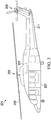
- FIG. 1 shows a schematic diagram of an example tiltrotor aircraft 101.
- Aircraft 101 includes a fuselage 103 with attached wings 105.
- Nacelles 107 are carried at the outboard ends of wings 105 and are rotatable between the helicopter-mode position shown and a forward-facing airplane-mode position (not shown).
- Nacelles 107 carry engines and transmissions 109 for powering rotor systems 111 in rotation.
- An engine may be an internal combustion engine, an electrical power source and associated motor, or any other suitable means for powering rotor system 111.
- Each rotor system 111 is illustrated as having three blades 113.
- Spinning covers 115 and nacelles 107 substantially enclose transmission 109, obscuring transmission 109 from view in figure 1 .
- the tiltrotor aircraft 101 includes a drive train that includes subassemblies generally indicated at 301 and described below for driving the rotor systems 111.
- the drive train subassemblies 301 can include gearboxes, shafts, couplings, and respective sprag overrunning one-way clutches as disclosed herein.
- FIG 2 shows a schematic diagram of an example rotorcraft 201, which also constitutes an aircraft.
- Rotorcraft 201 has a rotor system 203 with multiple rotor blades 205. The pitch of each rotor blade 205 can be manipulated in order to selectively control direction, thrust, and lift of rotorcraft 201.
- Rotorcraft 201 can further include a fuselage 207, anti-torque system 209, and an empennage 211.
- the rotorcraft 201 includes a drive train, including a subassembly generally indicated at 301 and described below for driving the rotor system 203.
- the drive train subassembly 301 can include a gearbox, shafts, couplings, and a sprag clutch.
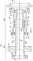
- FIG. 3 shows a cross-sectional view of an embodiment of a drive train subassembly 301.
- the drive train subassembly 301 includes a clutch portion 302A and a gear shaft portion 302B.
- the clutch portion 302A includes a sprag clutch 303.
- the gear shaft portion 302B includes a gear shaft 309B, which is integrally formed with an inner race 309A of the sprag clutch 303 so as to form an integrated inner race/gear shaft 309A/309B member.
- the integration of the inner race 309A and the gear shaft 309B can be accomplished by forming the inner race 309A/gear shaft 309B together as a single component.
- the inner race 309A can be formed separately from the gear shaft 309B, and then inner race 309A and gear shaft 309B can be colinearly fixed together, for example by friction welding, so as to be formed into a single continuous component.
- the integration of the output gear shaft 309B with the inner race 309A of the sprag clutch 303 as disclosed herein constitutes an example of a deviation from prior drive train assemblies.
- an output gear shaft would be a separate component from a sprag clutch.
- the sprag clutch would typically be connected to the output gear shaft via another component, such as a dog-bone shaft, that allows for axial misalignments between the output gear shaft and the sprag clutch.
- integration of the inner race 309A and the output gear shaft 309B into a single shaft component reduces parts count, weight, and complexity, which is desirable for aircraft applications.
- the sprag clutch 303 includes an outer race 305 having a longitudinal axis 307 therethrough, with the inner race 309A positioned concentrically within the outer race 305.
- An annular space 311 is therefore present between the inner race 309A and the outer race 305.
- One or more annular sprag rows 313 are positioned in the annular space 311 radially between the inner race 309A and the outer race 305. The exact number and configuration of sprags is determined according to principles known in the art for designing sprag clutches.
- Outer race 305 is adapted for connection to an input shaft (not shown) at an input end 318.
- the input end 318 of the outer race 305 can be a gear, such as a spiral bevel gear in the illustrated embodiment (note that the gear teeth are not shown in Figure 4 for simplicity of the view), or can be provided with internal and/or external crowned splines (not shown) which can receive torque from the input shaft.
- Outer race 305 can be adapted for connection to an input shaft using any one of a variety of known mechanical connections.
- the integrated inner race 309A and gear shaft 309B has an output end 315 at a distal end of the output gear shaft 309B.
- the clutch portion 302A includes a pair of overrunning bearings 319, 321 positioned radially between the outer race 305 and the inner race 309A of the sprag clutch 303.
- the first bearing 319 of the pair is positioned axially between the output end 315 and the sprag rows 313.
- the second bearing 321 is positioned axially on the opposite side of the sprag rows 313 from the output end 315.
- the sprag clutch 303 can be used in a variety of rotorcraft designs to transfer power from an engine to rotor system.
- a duplex bearing assembly 331 is provided for supporting the subassembly 301 in the axial direction.
- Alternative embodiments can include a single-row bearing in place of the duplex bearing assembly 331, depending on the input to the input end 318.
- the duplex bearing assembly 331 is desirable because it provides for more exact axial positioning than a single-row bearing, which is desirable for use with the spiral bevel gear on the input end 318.
- the configuration and location of the bearing assembly 331 can vary depending on the loading induced by the configuration of the outer race 305 and the gear shaft 309B. Also, depending on the input and output drive arrangements of the particular aircraft drivetrain, the loads on the bearings 331 can be modified such that the subassembly 301 can be held radially between roller bearings and axially with the duplex bearing assembly 331.
- the sprag clutch 303 allows the rotor system to continue to rotate faster than the engine so that the rotorcraft can perform an autorotation. In rotorcraft with more than one engine, the clutch is also used to allow one engine to be started up before the other engine(s).
- the input end of outer race 305 and output end 315 of the integrated inner race 309A and the gear shaft 309B are positioned at opposite ends of the longitudinal axis 307.
- the sprag clutch 303 is engaged and in driving mode, the outer race 305 and the integrated inner race 309A and gear shaft 309B rotate together as single shaft.
- the sprag clutch 303 is disengaged and allows the integrated inner race 309A and gear shaft 309B to rotate faster than the outer race 305 in order to allow for autorotation.
- the gear shaft portion 302B of the drive train subassembly 301 can extend into a downstream component of the drivetrain.
- the gear shaft 309B extends into a gearbox 401.
- the gear shaft 309B is integrally formed with the inner race 309A of the sprag clutch 303, the inner race 309A is part of a single continuous component that also serves as the gear shaft 309B that extends into the gearbox 401 for transmitting torque to downstream drivetrain components.
- the integrated inner race 309A and gear shaft 309B can be formed of metal, such as hardened steel, or can be formed of composite or ceramic material.
- An output gear 323 is formed on the gear shaft 309B between the sprag clutch 303 and the output end 315.
- the output gear 323 is a helical gear, but other types of gears can be used depending on the drivetrain configuration.
- the illustrated embodiment includes an integrally formed output gear 323, alternative embodiments can include an output gear that is a separate component that is attached to the gear shaft 309B.
- the gear shaft 309B can be provided with additional components (not shown) within the gearbox 401, such as one or more bearings, flanges, and retaining nuts.
- the embodiment of the integrated inner race 309A and the gear shaft 309B includes a generally cylindrical portion 325A that extends from within the sprag rows 313 to the output gear 323.
- the integrated inner race 309A and the gear shaft 309B further includes a pair of frustoconical portions 325B and 325C.
- the first frustoconical portion 325B extends from the output gear 323 away from the input end 318 such that the outside diameter of the first frustoconical portion 325B increases as it extends away from the output gear 323.
- the second frustoconical portion 325C extends from the sprag rows 313 to the bearing 321 such that the outside diameter of the second frustoconical portion 325C decreases from the sprag rows 313 to the bearing 321.
- shape of the integrated inner race 309A and the gear shaft 309B can differ from the illustrated embodiment as desired to accommodate different drivetrain configurations.
Landscapes
- Engineering & Computer Science (AREA)
- General Engineering & Computer Science (AREA)
- Mechanical Engineering (AREA)
- Aviation & Aerospace Engineering (AREA)
- Retarders (AREA)
- Gear Transmission (AREA)
Abstract
Description
- This disclosure generally relates to overrunning sprag clutches for the uni-directional transmission of torque. In one aspect, it relates to an overrunning sprag clutch having an improved output shaft configuration.
- Embodiments are illustrated by way of example in the accompanying figures, in which like reference numbers indicate similar parts, and in which:
-
Figure 1 shows a schematic diagram of an example of a tiltrotor aircraft; -
Figure 2 shows a schematic diagram of an example of a rotorcraft; -
Figure 3 shows a cross-sectional view of an exemplary embodiment of a drive train subassembly according to the present disclosure; and -
Figure 4 shows partial a cross-sectional view and partial side view of the drive train subassembly shown inFigure 3 . -
Figure 1 shows a schematic diagram of anexample tiltrotor aircraft 101.Aircraft 101 includes afuselage 103 with attachedwings 105. Nacelles 107 are carried at the outboard ends ofwings 105 and are rotatable between the helicopter-mode position shown and a forward-facing airplane-mode position (not shown). Nacelles 107 carry engines andtransmissions 109 for poweringrotor systems 111 in rotation. An engine may be an internal combustion engine, an electrical power source and associated motor, or any other suitable means for poweringrotor system 111. Eachrotor system 111 is illustrated as having threeblades 113. Spinning covers 115 andnacelles 107 substantially enclosetransmission 109, obscuringtransmission 109 from view infigure 1 . Thetiltrotor aircraft 101 includes a drive train that includes subassemblies generally indicated at 301 and described below for driving therotor systems 111. Thedrive train subassemblies 301 can include gearboxes, shafts, couplings, and respective sprag overrunning one-way clutches as disclosed herein. -
Figure 2 shows a schematic diagram of anexample rotorcraft 201, which also constitutes an aircraft. Rotorcraft 201 has arotor system 203 withmultiple rotor blades 205. The pitch of eachrotor blade 205 can be manipulated in order to selectively control direction, thrust, and lift ofrotorcraft 201. Rotorcraft 201 can further include afuselage 207,anti-torque system 209, and anempennage 211. Therotorcraft 201 includes a drive train, including a subassembly generally indicated at 301 and described below for driving therotor system 203. Thedrive train subassembly 301 can include a gearbox, shafts, couplings, and a sprag clutch. -
Figure 3 shows a cross-sectional view of an embodiment of adrive train subassembly 301. Thedrive train subassembly 301 includes aclutch portion 302A and agear shaft portion 302B. Theclutch portion 302A includes asprag clutch 303. Thegear shaft portion 302B includes agear shaft 309B, which is integrally formed with aninner race 309A of thesprag clutch 303 so as to form an integrated inner race/gear shaft 309A/309B member. The integration of theinner race 309A and thegear shaft 309B can be accomplished by forming theinner race 309A/gear shaft 309B together as a single component. Alternatively, in some embodiments theinner race 309A can be formed separately from thegear shaft 309B, and theninner race 309A andgear shaft 309B can be colinearly fixed together, for example by friction welding, so as to be formed into a single continuous component. - The integration of the
output gear shaft 309B with theinner race 309A of thesprag clutch 303 as disclosed herein constitutes an example of a deviation from prior drive train assemblies. Traditionally, an output gear shaft would be a separate component from a sprag clutch. The sprag clutch would typically be connected to the output gear shaft via another component, such as a dog-bone shaft, that allows for axial misalignments between the output gear shaft and the sprag clutch. However, integration of theinner race 309A and theoutput gear shaft 309B into a single shaft component reduces parts count, weight, and complexity, which is desirable for aircraft applications. - The
sprag clutch 303 includes anouter race 305 having alongitudinal axis 307 therethrough, with theinner race 309A positioned concentrically within theouter race 305. Anannular space 311 is therefore present between theinner race 309A and theouter race 305. One or moreannular sprag rows 313 are positioned in theannular space 311 radially between theinner race 309A and theouter race 305. The exact number and configuration of sprags is determined according to principles known in the art for designing sprag clutches.Outer race 305 is adapted for connection to an input shaft (not shown) at aninput end 318. For example, theinput end 318 of theouter race 305 can be a gear, such as a spiral bevel gear in the illustrated embodiment (note that the gear teeth are not shown inFigure 4 for simplicity of the view), or can be provided with internal and/or external crowned splines (not shown) which can receive torque from the input shaft.Outer race 305 can be adapted for connection to an input shaft using any one of a variety of known mechanical connections. The integratedinner race 309A andgear shaft 309B has anoutput end 315 at a distal end of theoutput gear shaft 309B. - The
clutch portion 302A includes a pair of overrunningbearings outer race 305 and theinner race 309A of thesprag clutch 303. The first bearing 319 of the pair is positioned axially between theoutput end 315 and thesprag rows 313. The second bearing 321 is positioned axially on the opposite side of thesprag rows 313 from theoutput end 315. - The
sprag clutch 303 can be used in a variety of rotorcraft designs to transfer power from an engine to rotor system. In the illustrated embodiment, aduplex bearing assembly 331 is provided for supporting thesubassembly 301 in the axial direction. Alternative embodiments can include a single-row bearing in place of theduplex bearing assembly 331, depending on the input to theinput end 318. In the illustrated embodiment, theduplex bearing assembly 331 is desirable because it provides for more exact axial positioning than a single-row bearing, which is desirable for use with the spiral bevel gear on theinput end 318. The configuration and location of thebearing assembly 331 can vary depending on the loading induced by the configuration of theouter race 305 and thegear shaft 309B. Also, depending on the input and output drive arrangements of the particular aircraft drivetrain, the loads on thebearings 331 can be modified such that thesubassembly 301 can be held radially between roller bearings and axially with theduplex bearing assembly 331. - In the event of an engine failure, the
sprag clutch 303 allows the rotor system to continue to rotate faster than the engine so that the rotorcraft can perform an autorotation. In rotorcraft with more than one engine, the clutch is also used to allow one engine to be started up before the other engine(s). The input end ofouter race 305 andoutput end 315 of the integratedinner race 309A and thegear shaft 309B are positioned at opposite ends of thelongitudinal axis 307. When thesprag clutch 303 is engaged and in driving mode, theouter race 305 and the integratedinner race 309A andgear shaft 309B rotate together as single shaft. However, in the event of an engine failure, thesprag clutch 303 is disengaged and allows the integratedinner race 309A andgear shaft 309B to rotate faster than theouter race 305 in order to allow for autorotation. - Referring now also to
Figure 4 , thegear shaft portion 302B of thedrive train subassembly 301 can extend into a downstream component of the drivetrain. For example, in the illustrated embodiment, thegear shaft 309B extends into agearbox 401. Since thegear shaft 309B is integrally formed with theinner race 309A of thesprag clutch 303, theinner race 309A is part of a single continuous component that also serves as thegear shaft 309B that extends into thegearbox 401 for transmitting torque to downstream drivetrain components. The integratedinner race 309A andgear shaft 309B can be formed of metal, such as hardened steel, or can be formed of composite or ceramic material. - An
output gear 323 is formed on thegear shaft 309B between thesprag clutch 303 and theoutput end 315. For example, in the illustrated embodiment theoutput gear 323 is a helical gear, but other types of gears can be used depending on the drivetrain configuration. Also, while the illustrated embodiment includes an integrally formedoutput gear 323, alternative embodiments can include an output gear that is a separate component that is attached to thegear shaft 309B. It will also be appreciated that thegear shaft 309B can be provided with additional components (not shown) within thegearbox 401, such as one or more bearings, flanges, and retaining nuts. - The embodiment of the integrated
inner race 309A and thegear shaft 309B includes a generallycylindrical portion 325A that extends from within thesprag rows 313 to theoutput gear 323. The integratedinner race 309A and thegear shaft 309B further includes a pair offrustoconical portions frustoconical portion 325B extends from theoutput gear 323 away from theinput end 318 such that the outside diameter of the firstfrustoconical portion 325B increases as it extends away from theoutput gear 323. The secondfrustoconical portion 325C extends from thesprag rows 313 to thebearing 321 such that the outside diameter of the secondfrustoconical portion 325C decreases from thesprag rows 313 to thebearing 321. However, it will be appreciated that the shape of the integratedinner race 309A and thegear shaft 309B can differ from the illustrated embodiment as desired to accommodate different drivetrain configurations. - While various embodiments in accordance with the principles disclosed herein have been described above, it should be understood that they have been presented by way of example only, and are not limiting. Thus, the breadth and scope of the claims should not be limited by any of the above-described exemplary embodiments, but should be defined only in accordance with the claims and their equivalents issuing from this disclosure. Furthermore, the above advantages and features are provided in described embodiments, but shall not limit the application of such issued claims to processes and structures accomplishing any or all of the above advantages. Also, the phrases "at least one of A, B, and C" and "A and/or B and/or C" should each be interpreted to include only A, only B, only C, or any combination of A, B, and C.
Claims (11)
- A drivetrain subassembly comprising:a clutch portion including a sprag clutch having an inner race that is configured to rotate about a longitudinal axis; anda gear shaft portion including a gear shaft integrally formed with the inner race of the sprag clutch so as to form an integrated inner race/gear shaft member,wherein the integrated inner race/gear shaft member is configured to rotate about the longitudinal axis for transmitting torque from the sprag clutch to a downstream drivetrain component.
- An aircraft comprising:a rotor system; anda drivetrain subassembly for transferring torque to the rotor system, the drivetrain subassembly comprising:a clutch portion including a sprag clutch having an inner race that is configured to rotate about a longitudinal axis; anda gear shaft portion including a gear shaft integrally formed with the inner race of the sprag clutch so as to form an integrated inner race/gear shaft member,wherein the integrated inner race/gear shaft member is configured to rotate about the longitudinal axis for transmitting torque from the sprag clutch towards the rotor system.
- The subassembly of claim 1 or the aircraft of claim 2, wherein the sprag clutch further comprises an outer race, wherein the inner race is positioned concentrically within the outer race.
- The subassembly or aircraft of claim 3, wherein the sprag clutch further comprises at least one sprag row between the inner race and the outer race.
- The subassembly of claim 1 or of claim 3 or of claim 4, or the aircraft of claim 2 or of claim 3 or of claim 4, wherein the clutch portion further comprises a first bearing positioned between the outer race and the inner race of the sprag clutch.
- The subassembly or aircraft of claim 5, wherein the clutch portion further comprises a second bearing positioned between the outer race and the inner race of the sprag clutch.
- The subassembly or aircraft of claim 6, wherein the sprag clutch further comprises at least one sprag row radially disposed between the inner race and the outer race and axially disposed between the first and second bearings.
- The subassembly of claim 1 or of any preceding claim, or the aircraft of claim 2 or of any preceding claim, wherein an output gear is formed on the gear shaft such that the sprag clutch is between the output gear and an input end of the integrated inner race/gear shaft member.
- The subassembly or aircraft of claim 8, wherein the gear shaft extends from the sprag clutch to within a gearbox.
- The subassembly or aircraft of claim 9, wherein the output gear is disposed within the gearbox.
- The subassembly or aircraft of claim 10, wherein the output gear is a helical gear.
Applications Claiming Priority (1)
| Application Number | Priority Date | Filing Date | Title |
|---|---|---|---|
| US15/375,134 US20180163795A1 (en) | 2016-12-11 | 2016-12-11 | Drivetrain subassembly having an integrated sprag clutch race and gear shaft member |
Publications (2)
| Publication Number | Publication Date |
|---|---|
| EP3333073A1 true EP3333073A1 (en) | 2018-06-13 |
| EP3333073B1 EP3333073B1 (en) | 2019-03-20 |
Family
ID=60582510
Family Applications (1)
| Application Number | Title | Priority Date | Filing Date |
|---|---|---|---|
| EP17205640.0A Active EP3333073B1 (en) | 2016-12-11 | 2017-12-06 | Drivetrain subassembly having an integrated sprag clutch race and gear shaft member |
Country Status (2)
| Country | Link |
|---|---|
| US (1) | US20180163795A1 (en) |
| EP (1) | EP3333073B1 (en) |
Cited By (2)
| Publication number | Priority date | Publication date | Assignee | Title |
|---|---|---|---|---|
| EP3919376A1 (en) * | 2020-06-01 | 2021-12-08 | Bell Textron Inc. | Gearbox with coaxial input and output shafts |
| US11420760B2 (en) | 2020-06-29 | 2022-08-23 | Textron Innovations Inc. | Sealed coaxial input and output shafts |
Families Citing this family (4)
| Publication number | Priority date | Publication date | Assignee | Title |
|---|---|---|---|---|
| CN112572784B (en) * | 2021-02-23 | 2021-05-25 | 北京清航紫荆装备科技有限公司 | A power unit and output mechanism of an unmanned helicopter |
| US11708156B2 (en) * | 2021-10-20 | 2023-07-25 | Textron Innovations Inc. | Friction welded raceways for use in rotorcraft propulsion assemblies |
| US12352323B1 (en) * | 2024-06-13 | 2025-07-08 | Textron Innovations Inc. | Sprag clutch system for rotorcraft |
| US20260085741A1 (en) * | 2024-09-20 | 2026-03-26 | Pratt & Whitney Canada Corp. | Clutch assembly for an aircraft propulsion system gear train |
Citations (2)
| Publication number | Priority date | Publication date | Assignee | Title |
|---|---|---|---|---|
| US5722522A (en) * | 1996-06-05 | 1998-03-03 | Bell Helicopter Textron, Inc. | Overrunning multiple-row sprag clutch |
| US20090224096A1 (en) * | 2008-03-06 | 2009-09-10 | Karem Aircraft, Inc. | Rotorcraft engine and rotor speed synchronization |
Family Cites Families (12)
| Publication number | Priority date | Publication date | Assignee | Title |
|---|---|---|---|---|
| US3907219A (en) * | 1972-10-16 | 1975-09-23 | Jack W Pharris | High speed, long range turbo-jet aircraft |
| US4609165A (en) * | 1983-04-25 | 1986-09-02 | Hughes Helicopters, Inc. | Helicopter auxiliary energy system |
| US4697675A (en) * | 1986-06-02 | 1987-10-06 | Emerson Electric Co. | Shaft aligned backstop for a reducer |
| US5135442A (en) * | 1990-02-12 | 1992-08-04 | Lucas Western, Inc. | Gear arrangement for transmitting torque through an angle |
| US5249666A (en) * | 1992-04-03 | 1993-10-05 | The Falk Corporation | Load compensator for geared holdback devices |
| US5485905A (en) * | 1994-04-01 | 1996-01-23 | Rader, Iii; H. John | Lightweight overrunning clutch assembly |
| KR19980064247A (en) * | 1996-12-19 | 1998-10-07 | 윌리엄비.켐플러 | Continuous automatic rotation of wire bonding capillaries |
| US6629590B2 (en) * | 2000-11-17 | 2003-10-07 | The Hilliard Corporation | Spring assembly for a bi-directional overrunning clutch |
| US20040119261A1 (en) * | 2002-12-24 | 2004-06-24 | Troutman William E. | Modular drive system |
| JP4850129B2 (en) * | 2007-06-01 | 2012-01-11 | 富士重工業株式会社 | Final reduction gear |
| US8863924B2 (en) * | 2011-10-24 | 2014-10-21 | Bell Helicopter Textron Inc. | Hybrid overrunning clutch assembly and method of making same |
| US9797503B2 (en) * | 2015-05-12 | 2017-10-24 | Caterpillar Inc. | Direct torque path differential having spiderless pinions |
-
2016
- 2016-12-11 US US15/375,134 patent/US20180163795A1/en not_active Abandoned
-
2017
- 2017-12-06 EP EP17205640.0A patent/EP3333073B1/en active Active
Patent Citations (2)
| Publication number | Priority date | Publication date | Assignee | Title |
|---|---|---|---|---|
| US5722522A (en) * | 1996-06-05 | 1998-03-03 | Bell Helicopter Textron, Inc. | Overrunning multiple-row sprag clutch |
| US20090224096A1 (en) * | 2008-03-06 | 2009-09-10 | Karem Aircraft, Inc. | Rotorcraft engine and rotor speed synchronization |
Cited By (3)
| Publication number | Priority date | Publication date | Assignee | Title |
|---|---|---|---|---|
| EP3919376A1 (en) * | 2020-06-01 | 2021-12-08 | Bell Textron Inc. | Gearbox with coaxial input and output shafts |
| US11731779B2 (en) | 2020-06-01 | 2023-08-22 | Textron Innovations Inc. | Drivetrain for an aircraft including gearbox with coaxial input and output shafts |
| US11420760B2 (en) | 2020-06-29 | 2022-08-23 | Textron Innovations Inc. | Sealed coaxial input and output shafts |
Also Published As
| Publication number | Publication date |
|---|---|
| EP3333073B1 (en) | 2019-03-20 |
| US20180163795A1 (en) | 2018-06-14 |
Similar Documents
| Publication | Publication Date | Title |
|---|---|---|
| EP3333073B1 (en) | Drivetrain subassembly having an integrated sprag clutch race and gear shaft member | |
| EP3361122B1 (en) | Planetary gearbox for gas turbine engine | |
| US8231503B2 (en) | Torque balancing gearbox | |
| CN105605187B (en) | Electronics rear drive module with split type half shaft flange | |
| EP3038906B1 (en) | Light weight propulsor gearbox | |
| US8870538B2 (en) | Counter rotating facegear gearbox | |
| WO2008002474A2 (en) | Separable under load shaft coupling | |
| EP3608143B1 (en) | Drive axle system having a planetary interaxle differential unit | |
| KR102698325B1 (en) | Hover-capable aircraft | |
| US3249187A (en) | One way positive clutch connected in parallel with overload release friction coupling | |
| US11104430B2 (en) | Multimode powertrains for multi engine rotorcraft | |
| US10618642B2 (en) | Power transmission system and an aircraft having a rotary wing | |
| US20190055011A1 (en) | Drive train | |
| EP3385557B1 (en) | Clutch device for gas turbine engine | |
| US12313131B2 (en) | Electric propulsion systems | |
| EP3287654A1 (en) | Flexible coupling arrangements for drive systems | |
| US4609165A (en) | Helicopter auxiliary energy system | |
| US10724625B2 (en) | Torsionally compliant geartrain carrier assembly | |
| CN108331848B (en) | Crowning of splines in a direction perpendicular to the tooth flanks of the splines | |
| CN110873156A (en) | Transmission for an engine with two power inputs | |
| EP0876955A2 (en) | Torque-dividing transmission, particularly for aircraft | |
| EP0023393B1 (en) | Freewheel devices | |
| EP3486515B1 (en) | Splined coupling | |
| EP4328133B1 (en) | Rotary shaft for an aircraft | |
| EP3431795B1 (en) | Gear transmission for aeronautical applications |
Legal Events
| Date | Code | Title | Description |
|---|---|---|---|
| STAA | Information on the status of an ep patent application or granted ep patent |
Free format text: STATUS: EXAMINATION IS IN PROGRESS |
|
| PUAI | Public reference made under article 153(3) epc to a published international application that has entered the european phase |
Free format text: ORIGINAL CODE: 0009012 |
|
| 17P | Request for examination filed |
Effective date: 20171206 |
|
| AK | Designated contracting states |
Kind code of ref document: A1 Designated state(s): AL AT BE BG CH CY CZ DE DK EE ES FI FR GB GR HR HU IE IS IT LI LT LU LV MC MK MT NL NO PL PT RO RS SE SI SK SM TR |
|
| AX | Request for extension of the european patent |
Extension state: BA ME |
|
| GRAP | Despatch of communication of intention to grant a patent |
Free format text: ORIGINAL CODE: EPIDOSNIGR1 |
|
| STAA | Information on the status of an ep patent application or granted ep patent |
Free format text: STATUS: GRANT OF PATENT IS INTENDED |
|
| RIC1 | Information provided on ipc code assigned before grant |
Ipc: B64C 29/00 20060101ALN20180911BHEP Ipc: B64C 27/12 20060101AFI20180911BHEP Ipc: F16D 41/07 20060101ALN20180911BHEP |
|
| INTG | Intention to grant announced |
Effective date: 20181002 |
|
| GRAS | Grant fee paid |
Free format text: ORIGINAL CODE: EPIDOSNIGR3 |
|
| GRAA | (expected) grant |
Free format text: ORIGINAL CODE: 0009210 |
|
| STAA | Information on the status of an ep patent application or granted ep patent |
Free format text: STATUS: THE PATENT HAS BEEN GRANTED |
|
| AK | Designated contracting states |
Kind code of ref document: B1 Designated state(s): AL AT BE BG CH CY CZ DE DK EE ES FI FR GB GR HR HU IE IS IT LI LT LU LV MC MK MT NL NO PL PT RO RS SE SI SK SM TR |
|
| REG | Reference to a national code |
Ref country code: GB Ref legal event code: FG4D |
|
| REG | Reference to a national code |
Ref country code: CH Ref legal event code: EP |
|
| REG | Reference to a national code |
Ref country code: DE Ref legal event code: R096 Ref document number: 602017002835 Country of ref document: DE |
|
| REG | Reference to a national code |
Ref country code: AT Ref legal event code: REF Ref document number: 1110260 Country of ref document: AT Kind code of ref document: T Effective date: 20190415 |
|
| REG | Reference to a national code |
Ref country code: IE Ref legal event code: FG4D |
|
| REG | Reference to a national code |
Ref country code: NL Ref legal event code: MP Effective date: 20190320 |
|
| PG25 | Lapsed in a contracting state [announced via postgrant information from national office to epo] |
Ref country code: FI Free format text: LAPSE BECAUSE OF FAILURE TO SUBMIT A TRANSLATION OF THE DESCRIPTION OR TO PAY THE FEE WITHIN THE PRESCRIBED TIME-LIMIT Effective date: 20190320 Ref country code: LT Free format text: LAPSE BECAUSE OF FAILURE TO SUBMIT A TRANSLATION OF THE DESCRIPTION OR TO PAY THE FEE WITHIN THE PRESCRIBED TIME-LIMIT Effective date: 20190320 Ref country code: SE Free format text: LAPSE BECAUSE OF FAILURE TO SUBMIT A TRANSLATION OF THE DESCRIPTION OR TO PAY THE FEE WITHIN THE PRESCRIBED TIME-LIMIT Effective date: 20190320 Ref country code: NO Free format text: LAPSE BECAUSE OF FAILURE TO SUBMIT A TRANSLATION OF THE DESCRIPTION OR TO PAY THE FEE WITHIN THE PRESCRIBED TIME-LIMIT Effective date: 20190620 |
|
| REG | Reference to a national code |
Ref country code: LT Ref legal event code: MG4D |
|
| PG25 | Lapsed in a contracting state [announced via postgrant information from national office to epo] |
Ref country code: RS Free format text: LAPSE BECAUSE OF FAILURE TO SUBMIT A TRANSLATION OF THE DESCRIPTION OR TO PAY THE FEE WITHIN THE PRESCRIBED TIME-LIMIT Effective date: 20190320 Ref country code: NL Free format text: LAPSE BECAUSE OF FAILURE TO SUBMIT A TRANSLATION OF THE DESCRIPTION OR TO PAY THE FEE WITHIN THE PRESCRIBED TIME-LIMIT Effective date: 20190320 Ref country code: HR Free format text: LAPSE BECAUSE OF FAILURE TO SUBMIT A TRANSLATION OF THE DESCRIPTION OR TO PAY THE FEE WITHIN THE PRESCRIBED TIME-LIMIT Effective date: 20190320 Ref country code: GR Free format text: LAPSE BECAUSE OF FAILURE TO SUBMIT A TRANSLATION OF THE DESCRIPTION OR TO PAY THE FEE WITHIN THE PRESCRIBED TIME-LIMIT Effective date: 20190621 Ref country code: BG Free format text: LAPSE BECAUSE OF FAILURE TO SUBMIT A TRANSLATION OF THE DESCRIPTION OR TO PAY THE FEE WITHIN THE PRESCRIBED TIME-LIMIT Effective date: 20190620 Ref country code: LV Free format text: LAPSE BECAUSE OF FAILURE TO SUBMIT A TRANSLATION OF THE DESCRIPTION OR TO PAY THE FEE WITHIN THE PRESCRIBED TIME-LIMIT Effective date: 20190320 |
|
| REG | Reference to a national code |
Ref country code: AT Ref legal event code: MK05 Ref document number: 1110260 Country of ref document: AT Kind code of ref document: T Effective date: 20190320 |
|
| PG25 | Lapsed in a contracting state [announced via postgrant information from national office to epo] |
Ref country code: RO Free format text: LAPSE BECAUSE OF FAILURE TO SUBMIT A TRANSLATION OF THE DESCRIPTION OR TO PAY THE FEE WITHIN THE PRESCRIBED TIME-LIMIT Effective date: 20190320 Ref country code: SK Free format text: LAPSE BECAUSE OF FAILURE TO SUBMIT A TRANSLATION OF THE DESCRIPTION OR TO PAY THE FEE WITHIN THE PRESCRIBED TIME-LIMIT Effective date: 20190320 Ref country code: EE Free format text: LAPSE BECAUSE OF FAILURE TO SUBMIT A TRANSLATION OF THE DESCRIPTION OR TO PAY THE FEE WITHIN THE PRESCRIBED TIME-LIMIT Effective date: 20190320 Ref country code: ES Free format text: LAPSE BECAUSE OF FAILURE TO SUBMIT A TRANSLATION OF THE DESCRIPTION OR TO PAY THE FEE WITHIN THE PRESCRIBED TIME-LIMIT Effective date: 20190320 Ref country code: AL Free format text: LAPSE BECAUSE OF FAILURE TO SUBMIT A TRANSLATION OF THE DESCRIPTION OR TO PAY THE FEE WITHIN THE PRESCRIBED TIME-LIMIT Effective date: 20190320 Ref country code: PT Free format text: LAPSE BECAUSE OF FAILURE TO SUBMIT A TRANSLATION OF THE DESCRIPTION OR TO PAY THE FEE WITHIN THE PRESCRIBED TIME-LIMIT Effective date: 20190720 Ref country code: CZ Free format text: LAPSE BECAUSE OF FAILURE TO SUBMIT A TRANSLATION OF THE DESCRIPTION OR TO PAY THE FEE WITHIN THE PRESCRIBED TIME-LIMIT Effective date: 20190320 |
|
| PG25 | Lapsed in a contracting state [announced via postgrant information from national office to epo] |
Ref country code: SM Free format text: LAPSE BECAUSE OF FAILURE TO SUBMIT A TRANSLATION OF THE DESCRIPTION OR TO PAY THE FEE WITHIN THE PRESCRIBED TIME-LIMIT Effective date: 20190320 Ref country code: PL Free format text: LAPSE BECAUSE OF FAILURE TO SUBMIT A TRANSLATION OF THE DESCRIPTION OR TO PAY THE FEE WITHIN THE PRESCRIBED TIME-LIMIT Effective date: 20190320 |
|
| PG25 | Lapsed in a contracting state [announced via postgrant information from national office to epo] |
Ref country code: AT Free format text: LAPSE BECAUSE OF FAILURE TO SUBMIT A TRANSLATION OF THE DESCRIPTION OR TO PAY THE FEE WITHIN THE PRESCRIBED TIME-LIMIT Effective date: 20190320 Ref country code: IS Free format text: LAPSE BECAUSE OF FAILURE TO SUBMIT A TRANSLATION OF THE DESCRIPTION OR TO PAY THE FEE WITHIN THE PRESCRIBED TIME-LIMIT Effective date: 20190720 |
|
| REG | Reference to a national code |
Ref country code: DE Ref legal event code: R097 Ref document number: 602017002835 Country of ref document: DE |
|
| PLBE | No opposition filed within time limit |
Free format text: ORIGINAL CODE: 0009261 |
|
| STAA | Information on the status of an ep patent application or granted ep patent |
Free format text: STATUS: NO OPPOSITION FILED WITHIN TIME LIMIT |
|
| PG25 | Lapsed in a contracting state [announced via postgrant information from national office to epo] |
Ref country code: DK Free format text: LAPSE BECAUSE OF FAILURE TO SUBMIT A TRANSLATION OF THE DESCRIPTION OR TO PAY THE FEE WITHIN THE PRESCRIBED TIME-LIMIT Effective date: 20190320 |
|
| 26N | No opposition filed |
Effective date: 20200102 |
|
| PG25 | Lapsed in a contracting state [announced via postgrant information from national office to epo] |
Ref country code: TR Free format text: LAPSE BECAUSE OF FAILURE TO SUBMIT A TRANSLATION OF THE DESCRIPTION OR TO PAY THE FEE WITHIN THE PRESCRIBED TIME-LIMIT Effective date: 20190320 |
|
| REG | Reference to a national code |
Ref country code: BE Ref legal event code: MM Effective date: 20191231 |
|
| PG25 | Lapsed in a contracting state [announced via postgrant information from national office to epo] |
Ref country code: MC Free format text: LAPSE BECAUSE OF FAILURE TO SUBMIT A TRANSLATION OF THE DESCRIPTION OR TO PAY THE FEE WITHIN THE PRESCRIBED TIME-LIMIT Effective date: 20190320 |
|
| PG25 | Lapsed in a contracting state [announced via postgrant information from national office to epo] |
Ref country code: IE Free format text: LAPSE BECAUSE OF NON-PAYMENT OF DUE FEES Effective date: 20191206 Ref country code: LU Free format text: LAPSE BECAUSE OF NON-PAYMENT OF DUE FEES Effective date: 20191206 |
|
| PG25 | Lapsed in a contracting state [announced via postgrant information from national office to epo] |
Ref country code: BE Free format text: LAPSE BECAUSE OF NON-PAYMENT OF DUE FEES Effective date: 20191231 |
|
| PG25 | Lapsed in a contracting state [announced via postgrant information from national office to epo] |
Ref country code: CY Free format text: LAPSE BECAUSE OF FAILURE TO SUBMIT A TRANSLATION OF THE DESCRIPTION OR TO PAY THE FEE WITHIN THE PRESCRIBED TIME-LIMIT Effective date: 20190320 |
|
| PG25 | Lapsed in a contracting state [announced via postgrant information from national office to epo] |
Ref country code: HU Free format text: LAPSE BECAUSE OF FAILURE TO SUBMIT A TRANSLATION OF THE DESCRIPTION OR TO PAY THE FEE WITHIN THE PRESCRIBED TIME-LIMIT; INVALID AB INITIO Effective date: 20171206 Ref country code: MT Free format text: LAPSE BECAUSE OF FAILURE TO SUBMIT A TRANSLATION OF THE DESCRIPTION OR TO PAY THE FEE WITHIN THE PRESCRIBED TIME-LIMIT Effective date: 20190320 |
|
| REG | Reference to a national code |
Ref country code: CH Ref legal event code: PL |
|
| PG25 | Lapsed in a contracting state [announced via postgrant information from national office to epo] |
Ref country code: SI Free format text: LAPSE BECAUSE OF FAILURE TO SUBMIT A TRANSLATION OF THE DESCRIPTION OR TO PAY THE FEE WITHIN THE PRESCRIBED TIME-LIMIT Effective date: 20190320 |
|
| PG25 | Lapsed in a contracting state [announced via postgrant information from national office to epo] |
Ref country code: CH Free format text: LAPSE BECAUSE OF NON-PAYMENT OF DUE FEES Effective date: 20201231 Ref country code: LI Free format text: LAPSE BECAUSE OF NON-PAYMENT OF DUE FEES Effective date: 20201231 |
|
| PG25 | Lapsed in a contracting state [announced via postgrant information from national office to epo] |
Ref country code: MK Free format text: LAPSE BECAUSE OF FAILURE TO SUBMIT A TRANSLATION OF THE DESCRIPTION OR TO PAY THE FEE WITHIN THE PRESCRIBED TIME-LIMIT Effective date: 20190320 |
|
| P01 | Opt-out of the competence of the unified patent court (upc) registered |
Effective date: 20230602 |
|
| PGFP | Annual fee paid to national office [announced via postgrant information from national office to epo] |
Ref country code: GB Payment date: 20251229 Year of fee payment: 9 |
|
| PGFP | Annual fee paid to national office [announced via postgrant information from national office to epo] |
Ref country code: IT Payment date: 20251219 Year of fee payment: 9 |
|
| PGFP | Annual fee paid to national office [announced via postgrant information from national office to epo] |
Ref country code: FR Payment date: 20251226 Year of fee payment: 9 |
|
| PGFP | Annual fee paid to national office [announced via postgrant information from national office to epo] |
Ref country code: DE Payment date: 20251229 Year of fee payment: 9 |