EP3333013A1 - Trailer in particular for horse transport - Google Patents
Trailer in particular for horse transport Download PDFInfo
- Publication number
- EP3333013A1 EP3333013A1 EP17205837.2A EP17205837A EP3333013A1 EP 3333013 A1 EP3333013 A1 EP 3333013A1 EP 17205837 A EP17205837 A EP 17205837A EP 3333013 A1 EP3333013 A1 EP 3333013A1
- Authority
- EP
- European Patent Office
- Prior art keywords
- horsebox
- partition
- sleeve
- vehicle
- pole
- Prior art date
- Legal status (The legal status is an assumption and is not a legal conclusion. Google has not performed a legal analysis and makes no representation as to the accuracy of the status listed.)
- Granted
Links
Images

Classifications
-
- B—PERFORMING OPERATIONS; TRANSPORTING
- B60—VEHICLES IN GENERAL
- B60P—VEHICLES ADAPTED FOR LOAD TRANSPORTATION OR TO TRANSPORT, TO CARRY, OR TO COMPRISE SPECIAL LOADS OR OBJECTS
- B60P3/00—Vehicles adapted to transport, to carry or to comprise special loads or objects
- B60P3/04—Vehicles adapted to transport, to carry or to comprise special loads or objects for transporting animals
Definitions
- the invention relates to a vehicle, more particularly for horse transport, comprising:
- a vehicle of this type is known from DE 93 09 517.1 U .
- the partition of this known vehicle divides the horsebox in two or more compartments for the transport of two or more horses.
- the partition extends from the bottom to approximately halfway the ceiling.
- a sleeve has been fitted in the bottom, in which sleeve one end of the partition pole is accommodated.
- the vehicle according to the invention is characterized in that the bottom end of the partition pole is present underneath the bottom at a distance from the bottom, and floor beams are present underneath the bottom of the horsebox where the part of the partition pole that is present underneath the bottom is connected to one or more of the bottom beams by guy elements, so that this part is secured in radial direction relative to the bottom of the horsebox and the partition pole is maintained in an upright position.
- the partition pole is locked in lateral direction in the tubular hole in the floor.
- the partition pole By securing in lateral direction also the part of the partition pole extending underneath the underside of the bottom, the partition pole is maintained in upright position in a sturdier way and the partition will better be able to keep the horse in the vehicle standing on its feet during transport, so that there will be less chance of accidents.
- the guy elements are connected to the bottom end of the partition pole.
- An advantageous embodiment of the vehicle according to the invention is characterized in that a sleeve open at the top and closed at the bottom is fitted to the bottom in the opening in the floor, where the part of the partition pole present underneath the bottom of the floor is accommodated in the sleeve and the sleeve is connected to one or more of the floor beams by means of the guy elements.
- the sleeve preferably contains an inner sleeve in which the bottom end of the partition pole is fitted.
- a further advantageous embodiment of the vehicle according to the invention is characterized in that at the top of the partition pole is provided an operating element (preferably a turning knob) which is connected via a transfer element (preferably a rod) to a securing mechanism provided with a securing element located in the bottom of the partition pole, where when the securing mechanism is operated the securing element (for example a pin) is brought outward until it hits the inside of the sleeve and thereby secures the partition pole in the sleeve.
- an operating element preferably a turning knob
- a transfer element preferably a rod
- a still further advantageous embodiment of the vehicle according to the invention is characterized in that the vehicle is a trailer and is provided with a coupling that is present at the front of the horsebox and is connected to the horsebox, for coupling the trailer to a towing vehicle.
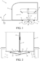
- Figs. 1 to 3 show an embodiment of the vehicle for horse transport according to the invention represented in a longitudinal cross sectional view and rear and bottom views respectively.
- the vehicle 1 is arranged as a trailer and has a horsebox 3 comprising wheels 5 connected to it. Underneath the bottom 7 of the horsebox are arranged floor beams 9 which form part of a chassis. At the front of the chassis is present a coupling 11 for coupling the vehicle to a towing vehicle. At the rear of the horsebox there is a ramp 13 for loading and unloading horses.
- the partition 15 dividing the space in the horsebox in two, so that two horses may be transported.
- the partition is affixed to a partition pole 17 which is connected to the bottom 7 of the horsebox.
- the partition and the partition pole extend from the bottom to roughly halfway the roof 19 of the horsebox.
- the bottom 7 of the horsebox has a hole 21 and a sleeve open at the top and closed at the bottom is fitted to the bottom at the location of this hole.
- the partition pole 17 is lowered with its bottom end in the sleeve and is locked in radial direction in the sleeve so that the partition pole is maintained in an upright position.
- the bottom of the sleeve 23 is connected by means of guy wires 25 or guy rods to the floor beams 9 underneath the bottom 7 of the horsebox.
- Fig. 4 separately shows for illustrative purposes the partition 15 with the partition pole 17 and the sleeve 23 with guy wires 25.
- Fig. 5 shows a cross-sectional view at the location of the sleeve along line V-V of Fig. 3 in which the securing mechanism is visible.
- the securing mechanism comprises a movable securing element (rotatable pin) which can be pushed against the inside of the sleeve.
- the securing element is connected via a transfer element 31 (rod) to an operating element 33 (turning knob, cf. Fig. 4 ).
- the securing mechanism has a right-angled transfer which converts a rotation of the rod to a rotation of the pin.
- Inside the sleeve 23 is located an inner sleeve 24 which accommodates the bottom end 17A of the partition pole 17.
Landscapes
- Engineering & Computer Science (AREA)
- Health & Medical Sciences (AREA)
- Public Health (AREA)
- Transportation (AREA)
- Mechanical Engineering (AREA)
- Fittings On The Vehicle Exterior For Carrying Loads, And Devices For Holding Or Mounting Articles (AREA)
Abstract
Description
- The invention relates to a vehicle, more particularly for horse transport, comprising:
- a horsebox provided with a bottom,
- wheels which are connected to the horsebox,
- a ramp which is present on one side of the vehicle, for loading and unloading horses,
- a partition extending in the horsebox, and
- at least a partition pole to which the partition is fitted, which partition pole is connected to the bottom of the horsebox,
- A vehicle of this type is known from
DE 93 09 517.1 U . The partition of this known vehicle divides the horsebox in two or more compartments for the transport of two or more horses. The partition extends from the bottom to approximately halfway the ceiling. A sleeve has been fitted in the bottom, in which sleeve one end of the partition pole is accommodated. - It is an object of the invention to provide a vehicle of the type defined in the opening paragraph which is safer than the known vehicle. To this end the vehicle according to the invention is characterized in that the bottom end of the partition pole is present underneath the bottom at a distance from the bottom, and floor beams are present underneath the bottom of the horsebox where the part of the partition pole that is present underneath the bottom is connected to one or more of the bottom beams by guy elements, so that this part is secured in radial direction relative to the bottom of the horsebox and the partition pole is maintained in an upright position. The partition pole is locked in lateral direction in the tubular hole in the floor. By securing in lateral direction also the part of the partition pole extending underneath the underside of the bottom, the partition pole is maintained in upright position in a sturdier way and the partition will better be able to keep the horse in the vehicle standing on its feet during transport, so that there will be less chance of accidents.
- Preferably, the guy elements are connected to the bottom end of the partition pole.
- An advantageous embodiment of the vehicle according to the invention is characterized in that a sleeve open at the top and closed at the bottom is fitted to the bottom in the opening in the floor, where the part of the partition pole present underneath the bottom of the floor is accommodated in the sleeve and the sleeve is connected to one or more of the floor beams by means of the guy elements. By not fitting the partition pole itself to the floor but by installing a sleeve underneath the floor which can accommodate the partition pole, the partition pole and the partition with it can be removed in a simple and rapid manner if so desired. The sleeve preferably contains an inner sleeve in which the bottom end of the partition pole is fitted.
- A further advantageous embodiment of the vehicle according to the invention is characterized in that at the top of the partition pole is provided an operating element (preferably a turning knob) which is connected via a transfer element (preferably a rod) to a securing mechanism provided with a securing element located in the bottom of the partition pole, where when the securing mechanism is operated the securing element (for example a pin) is brought outward until it hits the inside of the sleeve and thereby secures the partition pole in the sleeve.
- A still further advantageous embodiment of the vehicle according to the invention is characterized in that the vehicle is a trailer and is provided with a coupling that is present at the front of the horsebox and is connected to the horsebox, for coupling the trailer to a towing vehicle.
- The invention will be described hereinbelow in more detail based on an example of embodiment of the vehicle according to the invention represented in the drawing figures, in which:
-
Fig. 1 shows a longitudinal cross section of the vehicle; -
Fig. 2 shows a rear view of the vehicle; -
Fig. 3 shows bottom view of the vehicle; -
Fig. 4 shows the partition with partition pole and sleeve including guy wires; and -
Fig. 5 shows a cross-sectional view of the sleeve accommodating the end of the partition pole. -
Figs. 1 to 3 show an embodiment of the vehicle for horse transport according to the invention represented in a longitudinal cross sectional view and rear and bottom views respectively. Thevehicle 1 is arranged as a trailer and has ahorsebox 3 comprisingwheels 5 connected to it. Underneath thebottom 7 of the horsebox are arrangedfloor beams 9 which form part of a chassis. At the front of the chassis is present acoupling 11 for coupling the vehicle to a towing vehicle. At the rear of the horsebox there is aramp 13 for loading and unloading horses. - Inside the
horsebox 7 there is apartition 15 dividing the space in the horsebox in two, so that two horses may be transported. The partition is affixed to apartition pole 17 which is connected to thebottom 7 of the horsebox. The partition and the partition pole extend from the bottom to roughly halfway the roof 19 of the horsebox. Thebottom 7 of the horsebox has ahole 21 and a sleeve open at the top and closed at the bottom is fitted to the bottom at the location of this hole. Thepartition pole 17 is lowered with its bottom end in the sleeve and is locked in radial direction in the sleeve so that the partition pole is maintained in an upright position. The bottom of thesleeve 23 is connected by means ofguy wires 25 or guy rods to thefloor beams 9 underneath thebottom 7 of the horsebox. -
Fig. 4 separately shows for illustrative purposes thepartition 15 with thepartition pole 17 and thesleeve 23 withguy wires 25. - For locking the
partition pole 17 in thesleeve 23 there is a securing mechanism in the bottom of the partition pole.Fig. 5 shows a cross-sectional view at the location of the sleeve along line V-V ofFig. 3 in which the securing mechanism is visible. The securing mechanism comprises a movable securing element (rotatable pin) which can be pushed against the inside of the sleeve. The securing element is connected via a transfer element 31 (rod) to an operating element 33 (turning knob, cf.Fig. 4 ). The securing mechanism has a right-angled transfer which converts a rotation of the rod to a rotation of the pin. Inside thesleeve 23 is located aninner sleeve 24 which accommodates thebottom end 17A of thepartition pole 17. - Albeit the invention has been described in the foregoing based on the drawing figures, it should be observed that the invention is not by any manner or means restricted to the embodiment shown in the drawing figures. The invention also extends to all embodiments deviating from the embodiment shown in the drawing figures within the spirit and scope defined by the claims.
Claims (6)
- A vehicle, more particularly for horse transport, comprising:- a horsebox (3) provided with a bottom (7),- wheels (5) which are connected to the horsebox,- a ramp (13) which is present on one side of the vehicle, for loading and unloading horses,- a partition (15) extending in the horsebox, and- at least a partition pole (17) to which the partition is fitted, which partition pole is connected to the bottom (7) of the horsebox,where the bottom (7) of the horsebox (3) is provided with a hole (21) through which the partition pole (17) is projected, characterized in that the bottom end (17A) of the partition pole is present underneath the bottom at a distance from the bottom (7), and floor beams (9) are present underneath the bottom (7) of the horsebox where the part of the partition pole that is present underneath the bottom is connected to one or more of the bottom beams by guy elements (25), so that this part is secured in radial direction relative to the bottom of the horsebox and the partition pole is maintained in an upright position.
- A vehicle as claimed in claim 1, characterized in that the guy elements (25) are connected to the the bottom end (17a, 23A) of the partition pole (17).
- A vehicle as claimed in claim 1 or 2, characterized in that a sleeve (23) open at the top and closed at the bottom is fitted to the bottom (7) in the opening (21) in the floor, where the part of the partition pole (17) present underneath the bottom of the floor is accommodated in the sleeve and the sleeve is connected to one or more of the floor beams by means of the guy elements (25).
- A vehicle as claimed in claim 3, characterized in that the sleeve (23) contains an inner sleeve (24) in which the bottom end (17A) of the partition pole (17) is fitted.
- A vehicle as claimed ion claim 3 or 4, characterized in that at the top of the partition pole (17) is provided an operating element (33) which is connected via a transfer element (31) to a securing mechanism (27) provided with a securing element (29) located in the bottom of the partition pole, where when the securing mechanism is operated the securing element (29) is brought outward until it hits the inside of the sleeve (23) and thereby secures the partition pole (17) in the sleeve.
- A vehicle as claimed in any one of the preceding claims, characterized in that the vehicle is a trailer and is provided with a coupling (11) that is present at the front of the horsebox (3) and is connected to the horsebox, for coupling the trailer to a towing vehicle.
Applications Claiming Priority (2)
| Application Number | Priority Date | Filing Date | Title |
|---|---|---|---|
| NL2017961 | 2016-12-08 | ||
| NL2018265A NL2018265B1 (en) | 2016-12-08 | 2017-01-31 | Vehicle in particular for horse transport |
Publications (2)
| Publication Number | Publication Date |
|---|---|
| EP3333013A1 true EP3333013A1 (en) | 2018-06-13 |
| EP3333013B1 EP3333013B1 (en) | 2019-10-02 |
Family
ID=60781481
Family Applications (1)
| Application Number | Title | Priority Date | Filing Date |
|---|---|---|---|
| EP17205837.2A Active EP3333013B1 (en) | 2016-12-08 | 2017-12-07 | Trailer in particular for horse transport |
Country Status (1)
| Country | Link |
|---|---|
| EP (1) | EP3333013B1 (en) |
Citations (3)
| Publication number | Priority date | Publication date | Assignee | Title |
|---|---|---|---|---|
| US5174240A (en) * | 1992-06-15 | 1992-12-29 | Steve Darvill | Livestock trailer with catch gate |
| DE9309517U1 (en) * | 1993-06-26 | 1993-09-23 | Julius, Dieter, 42855 Remscheid | MOTOR VEHICLE TRAILER |
| DE102011011877A1 (en) * | 2011-02-21 | 2012-08-23 | Primero Trailer Gmbh & Co. Kg | Large animal transport trailer, especially horse trailer |
-
2017
- 2017-12-07 EP EP17205837.2A patent/EP3333013B1/en active Active
Patent Citations (3)
| Publication number | Priority date | Publication date | Assignee | Title |
|---|---|---|---|---|
| US5174240A (en) * | 1992-06-15 | 1992-12-29 | Steve Darvill | Livestock trailer with catch gate |
| DE9309517U1 (en) * | 1993-06-26 | 1993-09-23 | Julius, Dieter, 42855 Remscheid | MOTOR VEHICLE TRAILER |
| DE102011011877A1 (en) * | 2011-02-21 | 2012-08-23 | Primero Trailer Gmbh & Co. Kg | Large animal transport trailer, especially horse trailer |
Also Published As
| Publication number | Publication date |
|---|---|
| EP3333013B1 (en) | 2019-10-02 |
Similar Documents
| Publication | Publication Date | Title |
|---|---|---|
| US7635247B2 (en) | Telescoping vehicle step | |
| US9809271B2 (en) | Wheeled vehicle, especially for children | |
| US8485207B1 (en) | Shade system for vehicles | |
| US9440668B1 (en) | Umbrella folding table cart | |
| US20120126564A1 (en) | Vehicle tailgate having pivoting secondary tailgate therein | |
| US9738332B2 (en) | Kingpin stabilizer | |
| US10518707B2 (en) | Slidable step for mounting and dismounting a vehicle | |
| CN109890631A (en) | Detachable receiver | |
| US20070228761A1 (en) | Cargo bed step | |
| MX2015000743A (en) | Deploy and extend step pad. | |
| CN109068820A (en) | Fixing device and corresponding auxiliary hooking elements designed to be mounted on wheeled luggage | |
| US10486583B2 (en) | Multifunctional locking device for container of trailer | |
| EP3333013B1 (en) | Trailer in particular for horse transport | |
| US20170106926A1 (en) | Modular extension tube | |
| US20150086313A1 (en) | Retractable platform for vehicles | |
| US20170158110A1 (en) | Locking apparatus of container for trailer | |
| US9808060B2 (en) | Pull handle of luggage | |
| US9327567B2 (en) | Trailer hitch receiver locking apparatus | |
| US8915515B1 (en) | Gooseneck hitching system | |
| US20190047341A1 (en) | Coupling | |
| NL2018265B1 (en) | Vehicle in particular for horse transport | |
| US9340139B1 (en) | Trailer ramp system | |
| US20120261909A1 (en) | Expandable trailer | |
| EP3792109B1 (en) | Caravan with built-in access for driving motorcycles or other vehicles into same | |
| US20140357175A1 (en) | Multi-Platform Game Hoist |
Legal Events
| Date | Code | Title | Description |
|---|---|---|---|
| PUAI | Public reference made under article 153(3) epc to a published international application that has entered the european phase |
Free format text: ORIGINAL CODE: 0009012 |
|
| STAA | Information on the status of an ep patent application or granted ep patent |
Free format text: STATUS: THE APPLICATION HAS BEEN PUBLISHED |
|
| AK | Designated contracting states |
Kind code of ref document: A1 Designated state(s): AL AT BE BG CH CY CZ DE DK EE ES FI FR GB GR HR HU IE IS IT LI LT LU LV MC MK MT NL NO PL PT RO RS SE SI SK SM TR |
|
| AX | Request for extension of the european patent |
Extension state: BA ME |
|
| STAA | Information on the status of an ep patent application or granted ep patent |
Free format text: STATUS: REQUEST FOR EXAMINATION WAS MADE |
|
| 17P | Request for examination filed |
Effective date: 20181213 |
|
| RBV | Designated contracting states (corrected) |
Designated state(s): AL AT BE BG CH CY CZ DE DK EE ES FI FR GB GR HR HU IE IS IT LI LT LU LV MC MK MT NL NO PL PT RO RS SE SI SK SM TR |
|
| GRAP | Despatch of communication of intention to grant a patent |
Free format text: ORIGINAL CODE: EPIDOSNIGR1 |
|
| STAA | Information on the status of an ep patent application or granted ep patent |
Free format text: STATUS: GRANT OF PATENT IS INTENDED |
|
| INTG | Intention to grant announced |
Effective date: 20190426 |
|
| GRAS | Grant fee paid |
Free format text: ORIGINAL CODE: EPIDOSNIGR3 |
|
| GRAA | (expected) grant |
Free format text: ORIGINAL CODE: 0009210 |
|
| STAA | Information on the status of an ep patent application or granted ep patent |
Free format text: STATUS: THE PATENT HAS BEEN GRANTED |
|
| AK | Designated contracting states |
Kind code of ref document: B1 Designated state(s): AL AT BE BG CH CY CZ DE DK EE ES FI FR GB GR HR HU IE IS IT LI LT LU LV MC MK MT NL NO PL PT RO RS SE SI SK SM TR |
|
| REG | Reference to a national code |
Ref country code: GB Ref legal event code: FG4D |
|
| REG | Reference to a national code |
Ref country code: CH Ref legal event code: EP Ref country code: AT Ref legal event code: REF Ref document number: 1185821 Country of ref document: AT Kind code of ref document: T Effective date: 20191015 |
|
| REG | Reference to a national code |
Ref country code: DE Ref legal event code: R096 Ref document number: 602017007469 Country of ref document: DE |
|
| REG | Reference to a national code |
Ref country code: IE Ref legal event code: FG4D |
|
| REG | Reference to a national code |
Ref country code: NL Ref legal event code: FP |
|
| REG | Reference to a national code |
Ref country code: LT Ref legal event code: MG4D |
|
| REG | Reference to a national code |
Ref country code: AT Ref legal event code: MK05 Ref document number: 1185821 Country of ref document: AT Kind code of ref document: T Effective date: 20191002 |
|
| PG25 | Lapsed in a contracting state [announced via postgrant information from national office to epo] |
Ref country code: PT Free format text: LAPSE BECAUSE OF FAILURE TO SUBMIT A TRANSLATION OF THE DESCRIPTION OR TO PAY THE FEE WITHIN THE PRESCRIBED TIME-LIMIT Effective date: 20200203 Ref country code: AT Free format text: LAPSE BECAUSE OF FAILURE TO SUBMIT A TRANSLATION OF THE DESCRIPTION OR TO PAY THE FEE WITHIN THE PRESCRIBED TIME-LIMIT Effective date: 20191002 Ref country code: FI Free format text: LAPSE BECAUSE OF FAILURE TO SUBMIT A TRANSLATION OF THE DESCRIPTION OR TO PAY THE FEE WITHIN THE PRESCRIBED TIME-LIMIT Effective date: 20191002 Ref country code: GR Free format text: LAPSE BECAUSE OF FAILURE TO SUBMIT A TRANSLATION OF THE DESCRIPTION OR TO PAY THE FEE WITHIN THE PRESCRIBED TIME-LIMIT Effective date: 20200103 Ref country code: PL Free format text: LAPSE BECAUSE OF FAILURE TO SUBMIT A TRANSLATION OF THE DESCRIPTION OR TO PAY THE FEE WITHIN THE PRESCRIBED TIME-LIMIT Effective date: 20191002 Ref country code: LT Free format text: LAPSE BECAUSE OF FAILURE TO SUBMIT A TRANSLATION OF THE DESCRIPTION OR TO PAY THE FEE WITHIN THE PRESCRIBED TIME-LIMIT Effective date: 20191002 Ref country code: BG Free format text: LAPSE BECAUSE OF FAILURE TO SUBMIT A TRANSLATION OF THE DESCRIPTION OR TO PAY THE FEE WITHIN THE PRESCRIBED TIME-LIMIT Effective date: 20200102 Ref country code: NO Free format text: LAPSE BECAUSE OF FAILURE TO SUBMIT A TRANSLATION OF THE DESCRIPTION OR TO PAY THE FEE WITHIN THE PRESCRIBED TIME-LIMIT Effective date: 20200102 Ref country code: SE Free format text: LAPSE BECAUSE OF FAILURE TO SUBMIT A TRANSLATION OF THE DESCRIPTION OR TO PAY THE FEE WITHIN THE PRESCRIBED TIME-LIMIT Effective date: 20191002 Ref country code: LV Free format text: LAPSE BECAUSE OF FAILURE TO SUBMIT A TRANSLATION OF THE DESCRIPTION OR TO PAY THE FEE WITHIN THE PRESCRIBED TIME-LIMIT Effective date: 20191002 Ref country code: ES Free format text: LAPSE BECAUSE OF FAILURE TO SUBMIT A TRANSLATION OF THE DESCRIPTION OR TO PAY THE FEE WITHIN THE PRESCRIBED TIME-LIMIT Effective date: 20191002 |
|
| PG25 | Lapsed in a contracting state [announced via postgrant information from national office to epo] |
Ref country code: HR Free format text: LAPSE BECAUSE OF FAILURE TO SUBMIT A TRANSLATION OF THE DESCRIPTION OR TO PAY THE FEE WITHIN THE PRESCRIBED TIME-LIMIT Effective date: 20191002 Ref country code: IS Free format text: LAPSE BECAUSE OF FAILURE TO SUBMIT A TRANSLATION OF THE DESCRIPTION OR TO PAY THE FEE WITHIN THE PRESCRIBED TIME-LIMIT Effective date: 20200224 Ref country code: CZ Free format text: LAPSE BECAUSE OF FAILURE TO SUBMIT A TRANSLATION OF THE DESCRIPTION OR TO PAY THE FEE WITHIN THE PRESCRIBED TIME-LIMIT Effective date: 20191002 Ref country code: RS Free format text: LAPSE BECAUSE OF FAILURE TO SUBMIT A TRANSLATION OF THE DESCRIPTION OR TO PAY THE FEE WITHIN THE PRESCRIBED TIME-LIMIT Effective date: 20191002 |
|
| PG25 | Lapsed in a contracting state [announced via postgrant information from national office to epo] |
Ref country code: AL Free format text: LAPSE BECAUSE OF FAILURE TO SUBMIT A TRANSLATION OF THE DESCRIPTION OR TO PAY THE FEE WITHIN THE PRESCRIBED TIME-LIMIT Effective date: 20191002 |
|
| REG | Reference to a national code |
Ref country code: DE Ref legal event code: R097 Ref document number: 602017007469 Country of ref document: DE |
|
| PG2D | Information on lapse in contracting state deleted |
Ref country code: IS |
|
| PG25 | Lapsed in a contracting state [announced via postgrant information from national office to epo] |
Ref country code: EE Free format text: LAPSE BECAUSE OF FAILURE TO SUBMIT A TRANSLATION OF THE DESCRIPTION OR TO PAY THE FEE WITHIN THE PRESCRIBED TIME-LIMIT Effective date: 20191002 Ref country code: RO Free format text: LAPSE BECAUSE OF FAILURE TO SUBMIT A TRANSLATION OF THE DESCRIPTION OR TO PAY THE FEE WITHIN THE PRESCRIBED TIME-LIMIT Effective date: 20191002 Ref country code: DK Free format text: LAPSE BECAUSE OF FAILURE TO SUBMIT A TRANSLATION OF THE DESCRIPTION OR TO PAY THE FEE WITHIN THE PRESCRIBED TIME-LIMIT Effective date: 20191002 Ref country code: IS Free format text: LAPSE BECAUSE OF FAILURE TO SUBMIT A TRANSLATION OF THE DESCRIPTION OR TO PAY THE FEE WITHIN THE PRESCRIBED TIME-LIMIT Effective date: 20200202 |
|
| PLBE | No opposition filed within time limit |
Free format text: ORIGINAL CODE: 0009261 |
|
| STAA | Information on the status of an ep patent application or granted ep patent |
Free format text: STATUS: NO OPPOSITION FILED WITHIN TIME LIMIT |
|
| PG25 | Lapsed in a contracting state [announced via postgrant information from national office to epo] |
Ref country code: SM Free format text: LAPSE BECAUSE OF FAILURE TO SUBMIT A TRANSLATION OF THE DESCRIPTION OR TO PAY THE FEE WITHIN THE PRESCRIBED TIME-LIMIT Effective date: 20191002 Ref country code: MC Free format text: LAPSE BECAUSE OF FAILURE TO SUBMIT A TRANSLATION OF THE DESCRIPTION OR TO PAY THE FEE WITHIN THE PRESCRIBED TIME-LIMIT Effective date: 20191002 Ref country code: SK Free format text: LAPSE BECAUSE OF FAILURE TO SUBMIT A TRANSLATION OF THE DESCRIPTION OR TO PAY THE FEE WITHIN THE PRESCRIBED TIME-LIMIT Effective date: 20191002 Ref country code: IT Free format text: LAPSE BECAUSE OF FAILURE TO SUBMIT A TRANSLATION OF THE DESCRIPTION OR TO PAY THE FEE WITHIN THE PRESCRIBED TIME-LIMIT Effective date: 20191002 |
|
| 26N | No opposition filed |
Effective date: 20200703 |
|
| PG25 | Lapsed in a contracting state [announced via postgrant information from national office to epo] |
Ref country code: IE Free format text: LAPSE BECAUSE OF NON-PAYMENT OF DUE FEES Effective date: 20191207 Ref country code: LU Free format text: LAPSE BECAUSE OF NON-PAYMENT OF DUE FEES Effective date: 20191207 |
|
| PG25 | Lapsed in a contracting state [announced via postgrant information from national office to epo] |
Ref country code: SI Free format text: LAPSE BECAUSE OF FAILURE TO SUBMIT A TRANSLATION OF THE DESCRIPTION OR TO PAY THE FEE WITHIN THE PRESCRIBED TIME-LIMIT Effective date: 20191002 |
|
| PG25 | Lapsed in a contracting state [announced via postgrant information from national office to epo] |
Ref country code: CY Free format text: LAPSE BECAUSE OF FAILURE TO SUBMIT A TRANSLATION OF THE DESCRIPTION OR TO PAY THE FEE WITHIN THE PRESCRIBED TIME-LIMIT Effective date: 20191002 |
|
| PG25 | Lapsed in a contracting state [announced via postgrant information from national office to epo] |
Ref country code: MT Free format text: LAPSE BECAUSE OF FAILURE TO SUBMIT A TRANSLATION OF THE DESCRIPTION OR TO PAY THE FEE WITHIN THE PRESCRIBED TIME-LIMIT Effective date: 20191002 Ref country code: HU Free format text: LAPSE BECAUSE OF FAILURE TO SUBMIT A TRANSLATION OF THE DESCRIPTION OR TO PAY THE FEE WITHIN THE PRESCRIBED TIME-LIMIT; INVALID AB INITIO Effective date: 20171207 |
|
| PG25 | Lapsed in a contracting state [announced via postgrant information from national office to epo] |
Ref country code: TR Free format text: LAPSE BECAUSE OF FAILURE TO SUBMIT A TRANSLATION OF THE DESCRIPTION OR TO PAY THE FEE WITHIN THE PRESCRIBED TIME-LIMIT Effective date: 20191002 |
|
| PG25 | Lapsed in a contracting state [announced via postgrant information from national office to epo] |
Ref country code: MK Free format text: LAPSE BECAUSE OF FAILURE TO SUBMIT A TRANSLATION OF THE DESCRIPTION OR TO PAY THE FEE WITHIN THE PRESCRIBED TIME-LIMIT Effective date: 20191002 |
|
| REG | Reference to a national code |
Ref country code: CH Ref legal event code: U11 Free format text: ST27 STATUS EVENT CODE: U-0-0-U10-U11 (AS PROVIDED BY THE NATIONAL OFFICE) Effective date: 20260101 |
|
| PGFP | Annual fee paid to national office [announced via postgrant information from national office to epo] |
Ref country code: DE Payment date: 20251211 Year of fee payment: 9 |
|
| PGFP | Annual fee paid to national office [announced via postgrant information from national office to epo] |
Ref country code: GB Payment date: 20251219 Year of fee payment: 9 |
|
| PGFP | Annual fee paid to national office [announced via postgrant information from national office to epo] |
Ref country code: NL Payment date: 20251219 Year of fee payment: 9 Ref country code: FR Payment date: 20251229 Year of fee payment: 9 |
|
| PGFP | Annual fee paid to national office [announced via postgrant information from national office to epo] |
Ref country code: BE Payment date: 20251219 Year of fee payment: 9 |
|
| PGFP | Annual fee paid to national office [announced via postgrant information from national office to epo] |
Ref country code: CH Payment date: 20260101 Year of fee payment: 9 |