EP3332999A1 - Engine device support structure and engine device installation method - Google Patents
Engine device support structure and engine device installation method Download PDFInfo
- Publication number
- EP3332999A1 EP3332999A1 EP16835027.0A EP16835027A EP3332999A1 EP 3332999 A1 EP3332999 A1 EP 3332999A1 EP 16835027 A EP16835027 A EP 16835027A EP 3332999 A1 EP3332999 A1 EP 3332999A1
- Authority
- EP
- European Patent Office
- Prior art keywords
- elastic support
- engine unit
- support bodies
- central axis
- engine
- Prior art date
- Legal status (The legal status is an assumption and is not a legal conclusion. Google has not performed a legal analysis and makes no representation as to the accuracy of the status listed.)
- Granted
Links
Images


Classifications
-
- B—PERFORMING OPERATIONS; TRANSPORTING
- B60—VEHICLES IN GENERAL
- B60K—ARRANGEMENT OR MOUNTING OF PROPULSION UNITS OR OF TRANSMISSIONS IN VEHICLES; ARRANGEMENT OR MOUNTING OF PLURAL DIVERSE PRIME-MOVERS IN VEHICLES; AUXILIARY DRIVES FOR VEHICLES; INSTRUMENTATION OR DASHBOARDS FOR VEHICLES; ARRANGEMENTS IN CONNECTION WITH COOLING, AIR INTAKE, GAS EXHAUST OR FUEL SUPPLY OF PROPULSION UNITS IN VEHICLES
- B60K5/00—Arrangement or mounting of internal-combustion or jet-propulsion units
- B60K5/12—Arrangement of engine supports
- B60K5/1208—Resilient supports
- B60K5/1216—Resilient supports characterised by the location of the supports relative to the motor or to each other
-
- B—PERFORMING OPERATIONS; TRANSPORTING
- B60—VEHICLES IN GENERAL
- B60K—ARRANGEMENT OR MOUNTING OF PROPULSION UNITS OR OF TRANSMISSIONS IN VEHICLES; ARRANGEMENT OR MOUNTING OF PLURAL DIVERSE PRIME-MOVERS IN VEHICLES; AUXILIARY DRIVES FOR VEHICLES; INSTRUMENTATION OR DASHBOARDS FOR VEHICLES; ARRANGEMENTS IN CONNECTION WITH COOLING, AIR INTAKE, GAS EXHAUST OR FUEL SUPPLY OF PROPULSION UNITS IN VEHICLES
- B60K5/00—Arrangement or mounting of internal-combustion or jet-propulsion units
- B60K5/12—Arrangement of engine supports
-
- B—PERFORMING OPERATIONS; TRANSPORTING
- B60—VEHICLES IN GENERAL
- B60K—ARRANGEMENT OR MOUNTING OF PROPULSION UNITS OR OF TRANSMISSIONS IN VEHICLES; ARRANGEMENT OR MOUNTING OF PLURAL DIVERSE PRIME-MOVERS IN VEHICLES; AUXILIARY DRIVES FOR VEHICLES; INSTRUMENTATION OR DASHBOARDS FOR VEHICLES; ARRANGEMENTS IN CONNECTION WITH COOLING, AIR INTAKE, GAS EXHAUST OR FUEL SUPPLY OF PROPULSION UNITS IN VEHICLES
- B60K5/00—Arrangement or mounting of internal-combustion or jet-propulsion units
- B60K5/12—Arrangement of engine supports
- B60K5/1208—Resilient supports
-
- B—PERFORMING OPERATIONS; TRANSPORTING
- B60—VEHICLES IN GENERAL
- B60W—CONJOINT CONTROL OF VEHICLE SUB-UNITS OF DIFFERENT TYPE OR DIFFERENT FUNCTION; CONTROL SYSTEMS SPECIALLY ADAPTED FOR HYBRID VEHICLES; ROAD VEHICLE DRIVE CONTROL SYSTEMS FOR PURPOSES NOT RELATED TO THE CONTROL OF A PARTICULAR SUB-UNIT
- B60W30/00—Purposes of road vehicle drive control systems not related to the control of a particular sub-unit, e.g. of systems using conjoint control of vehicle sub-units
- B60W30/18—Propelling the vehicle
- B60W30/20—Reducing vibrations in the driveline
-
- F—MECHANICAL ENGINEERING; LIGHTING; HEATING; WEAPONS; BLASTING
- F16—ENGINEERING ELEMENTS AND UNITS; GENERAL MEASURES FOR PRODUCING AND MAINTAINING EFFECTIVE FUNCTIONING OF MACHINES OR INSTALLATIONS; THERMAL INSULATION IN GENERAL
- F16F—SPRINGS; SHOCK-ABSORBERS; MEANS FOR DAMPING VIBRATION
- F16F15/00—Suppression of vibrations in systems; Means or arrangements for avoiding or reducing out-of-balance forces, e.g. due to motion
- F16F15/02—Suppression of vibrations of non-rotating, e.g. reciprocating systems; Suppression of vibrations of rotating systems by use of members not moving with the rotating systems
- F16F15/04—Suppression of vibrations of non-rotating, e.g. reciprocating systems; Suppression of vibrations of rotating systems by use of members not moving with the rotating systems using elastic means
-
- F—MECHANICAL ENGINEERING; LIGHTING; HEATING; WEAPONS; BLASTING
- F16—ENGINEERING ELEMENTS AND UNITS; GENERAL MEASURES FOR PRODUCING AND MAINTAINING EFFECTIVE FUNCTIONING OF MACHINES OR INSTALLATIONS; THERMAL INSULATION IN GENERAL
- F16F—SPRINGS; SHOCK-ABSORBERS; MEANS FOR DAMPING VIBRATION
- F16F9/00—Springs, vibration-dampers, shock-absorbers, or similarly-constructed movement-dampers using a fluid or the equivalent as damping medium
- F16F9/32—Details
- F16F9/3207—Constructional features
-
- F—MECHANICAL ENGINEERING; LIGHTING; HEATING; WEAPONS; BLASTING
- F16—ENGINEERING ELEMENTS AND UNITS; GENERAL MEASURES FOR PRODUCING AND MAINTAINING EFFECTIVE FUNCTIONING OF MACHINES OR INSTALLATIONS; THERMAL INSULATION IN GENERAL
- F16M—FRAMES, CASINGS OR BEDS OF ENGINES, MACHINES OR APPARATUS, NOT SPECIFIC TO ENGINES, MACHINES OR APPARATUS PROVIDED FOR ELSEWHERE; STANDS; SUPPORTS
- F16M7/00—Details of attaching or adjusting engine beds, frames, or supporting-legs on foundation or base; Attaching non-moving engine parts, e.g. cylinder blocks
-
- F—MECHANICAL ENGINEERING; LIGHTING; HEATING; WEAPONS; BLASTING
- F02—COMBUSTION ENGINES; HOT-GAS OR COMBUSTION-PRODUCT ENGINE PLANTS
- F02B—INTERNAL-COMBUSTION PISTON ENGINES; COMBUSTION ENGINES IN GENERAL
- F02B75/00—Other engines
- F02B75/16—Engines characterised by number of cylinders, e.g. single-cylinder engines
- F02B75/18—Multi-cylinder engines
- F02B2075/1804—Number of cylinders
- F02B2075/1812—Number of cylinders three
-
- F—MECHANICAL ENGINEERING; LIGHTING; HEATING; WEAPONS; BLASTING
- F16—ENGINEERING ELEMENTS AND UNITS; GENERAL MEASURES FOR PRODUCING AND MAINTAINING EFFECTIVE FUNCTIONING OF MACHINES OR INSTALLATIONS; THERMAL INSULATION IN GENERAL
- F16F—SPRINGS; SHOCK-ABSORBERS; MEANS FOR DAMPING VIBRATION
- F16F15/00—Suppression of vibrations in systems; Means or arrangements for avoiding or reducing out-of-balance forces, e.g. due to motion
- F16F15/02—Suppression of vibrations of non-rotating, e.g. reciprocating systems; Suppression of vibrations of rotating systems by use of members not moving with the rotating systems
- F16F15/04—Suppression of vibrations of non-rotating, e.g. reciprocating systems; Suppression of vibrations of rotating systems by use of members not moving with the rotating systems using elastic means
- F16F15/08—Suppression of vibrations of non-rotating, e.g. reciprocating systems; Suppression of vibrations of rotating systems by use of members not moving with the rotating systems using elastic means with rubber springs ; with springs made of rubber and metal
Definitions
- the present invention relates to an engine unit support structure with an engine unit mounted on a mount via elastic support bodies.
- An engine unit support structure for supporting an engine unit using elastic support bodies (elastic members) has been known as an art employed when mounting the engine unit on a mount (see
- Patent Document 1 for instance.
- Patent Document 1 Japanese Unexamined Patent Application Publication No. 2005-247249
- three-cylinder engines are mainly used for small construction machinery, such as compact excavators.
- first-order engine rotation same frequency as a engine rotation frequency
- 1.5th-order engine rotation same frequency as 1.5 times the engine rotation frequency
- the present invention provides an engine unit support structure and the like, featuring excellent vibration absorption performance for the pitching vibration, for an engine unit having a three-cylinder engine.
- An engine unit support structure includes an engine unit having a three-cylinder engine, a mount for mounting the engine unit, and a plurality of elastic support bodies coupled to the engine unit and the mount to support the engine unit.
- the plurality of elastic support bodies include a plurality of first elastic support bodies and a plurality of second elastic support bodies .
- the second elastic support bodies are so disposed as to be orthogonal to a rolling rotation central axis of the engine unit and astride a virtual plane including a pitching rotation central axis of the engine unit, and the first elastic support bodies are disposed in a position closer to the pitching rotation central axis than the second elastic support bodies and astride the virtual plane.
- a method for mounting an engine unit to constitute an engine unit support structure includes providing first elastic support bodies and second elastic support bodies in such positions that a load of the engine unit is borne first by the first elastic support bodies then by the second elastic support bodies when coupling the engine unit to the first elastic support bodies and the second elastic support bodies coupled to a mount from above the first elastic support bodies and the second elastic support bodies; and then coupling the engine unit and the first elastic support bodies together and coupling the engine unit and the second elastic support bodies together such that the load of the engine unit is borne by the first elastic support bodies and the second elastic support bodied in a distributed manner.
- an engine unit support structure 1 includes an engine unit 2, a mount 3, and a plurality of elastic support bodies 4.
- the engine unit 2 is of a construction having a three-cylinder engine 22 which has a cooling fan 21 for cooling the engine and a hydraulic pump 23 driven by the engine 22.
- the mount 3 is a vehicle frame constituting a mechanical floor of the operating machine, or a mount attached to the vehicle frame.
- the engine unit 2 is equipped with a cooling fan 21 on one end side of the engine 22 (on one end side in the extension direction of a not-shown output shaft (crank shaft) of the engine 22) and the hydraulic pump 23 on the other end side of the engine 22, as shown in FIG. 1 and FIG. 2 , for instance.
- the elastic support bodies 4 may be elastic support bodies having columnar rubber members as columnar elastic bodies, for instance.
- the elastic support bodies 4, at a lower end as one end thereof, are each coupled to the mount 3 as a vibration receiver via a joint member 41, such as a bracket, provided on the mount 3.
- the elastic support bodies 4, at an upper end as the other end thereof, are each coupled to the engine unit 2 as a vibration generator via a joint member 42, such as a bracket, provided on left and right sides 22S, 22S of the engine unit 2.
- the plurality of elastic support bodies 4, 4, ... include a pair of first elastic support bodies 4A, 4A disposed orthogonal to a pitching rotation central axis 22B of the engine unit 2 and astride a virtual plane 22D (see FIG. 1A, FIG. 1C , FIG. 2A, FIG. 2C ) including a rolling rotation central axis 22A of the engine unit 2 and two pairs of second elastic support bodies 4B, 4B, 4B, 4B, disposed astride the virtual plane 22D.
- the rolling rotation central axis 22A of the engine unit 2 is an axis extending in a front-rear direction of the engine unit 2 which is a center of rotation when the engine unit 2 rotates and vibrates.
- the pitching rotation central axis 22B of the engine unit 2 is the axis extending in a left-right direction of the engine unit 2 which is a center of rotation when the engine unit 2 rotates and vibrates.
- FIG. 1 and FIG. 2 illustrate the rolling rotation central axis 22A passing through a gravity center G of the engine unit 2 and the pitching rotation central axis 22B passing through the gravity center G of the engine unit 2.
- the rolling rotation central axis 22A and the pitching rotation central axis 22B do not pass through the gravity center G of the engine unit 2.
- a pair of first elastic support bodies 4A, 4A is so located as to be along the left and right sides 22S, 22S of the engine unit 2.
- each of the pair of first elastic support bodies 4A, 4A is disposed near the pitching rotation central axis 22B of the engine unit 2, and more preferably orthogonal to the rolling rotation central axis 22A of the engine unit 2 and on a virtual plane 22E (see FIG. 1B and FIG. 2B ) including the pitching rotation central axis 22B of the engine unit 2.
- first elastic support bodies 4A are disposed on the axis line of the pitching rotation central axis 22B.
- the first elastic support bodies 4A being disposed on the axis line of the pitching rotation central axis 22B means that the first elastic support bodies 4A are located in positions where the pitching rotation central axis 22B of the engine unit 2 passes. More preferably, the first elastic support bodies 4A are disposed such that the pitching rotation central axis 22B of the engine unit 2 passes through the gravity center of the first elastic support bodies 4A. This will improve the vibration absorption performance for the pitching vibration of low frequency peculiar to the three-cylinder engine 22.
- a mount 31 having a mounting surface higher than a mounting surface of the mount 3 is to be provided.
- the first elastic support bodies 4A are to be mounted on the mounting surface of the mount 31.
- the first elastic support bodies 4A may be disposed on the virtual plane 22E below the pitching rotation central axis 22B. In such a case, it is preferable that the gravity center of the first elastic support bodies 4A is located directly underneath the pitching rotation central axis 22B.
- the first elastic support bodies 4A may be disposed on the virtual plane 22E above the pitching rotation central axis 22B. In such a case, it is preferable that the gravity center of the first elastic support bodies 4A is located directly above the pitching rotation central axis 22B.
- the pair of first elastic support bodies 4A, 4A is disposed in positions an equal distance from the rolling rotation central axis 22A of the engine unit 2
- two pairs of second elastic support bodies 4B, 4B, 4B, 4B are so located as to be along the left and right sides 22S, 22S of the engine unit 2. At the same time, they are disposed in positions farther from the pitching rotation central axis 22B of the engine unit 2 than the first elastic support bodies 4A.
- One pair of second elastic support bodies 4B, 4B is disposed in positions an equal distance from the rolling rotation central axis 22A of the engine unit 2.
- the other pair of second elastic support bodies 4B, 4B is disposed in positions an equal distance from the rolling rotation central axis 22A of the engine unit 2.
- the engine unit support structure 1 is installed such that the second elastic support bodies 4B are located astride the virtual plane 22D. Also, the first elastic support bodies 4A are closer to the pitching rotation central axis 22B than the second elastic support bodies 4B and astride the virtual plane 22D.
- a pair of first elastic support bodies 4A, 4A is so arranged as to be along the left and right sides 22S, 22S of the engine unit 2.
- the pair of first elastic support bodies 4A, 4A is disposed near the pitching rotation central axis 22B of the engine unit 2, and more preferably orthogonal to the rolling rotation central axis 22A of the engine unit 2 and on a virtual plane 22E including the pitching rotation central axis 22B of the engine unit 2.
- two pairs of second elastic support bodies 4B, 4B, 4B, 4B are so arranged as to be along the left and right sides 22S, 22S of the engine unit 2, and they are disposed in positions farther from the pitching rotation central axis 22B of the engine unit 2 than the first elastic support bodies 4A.
- the provision of the pair of first elastic support bodies 4A, 4A will reduce the distributed load of the engine unit 2 to be borne by each of the four second elastic support bodies 4B, 4B, 4B, 4B. And this can make a spring constant of the second elastic support body 4B smaller.
- the engine unit support structure can excel in the vibration absorption performance for controlling the pitching vibration of low frequency peculiar to the three-cylinder engine 22.
- a pair of first elastic support bodies 4A, 4A is disposed near the pitching rotation central axis 22B of the engine unit 2, and more preferably orthogonal to the rolling rotation central axis 22A of the engine unit 2 and on the virtual plane 22E including the pitching rotation central axis 22B of the engine unit 2.
- the spring constant of the second elastic support body 4B can be made smaller.
- the influence of the pair of first elastic support bodies 4A, 4A on the pitching vibration of low frequency peculiar to the three-cylinder engine 22 can be made smaller.
- the engine unit support structure 1 featuring superior vibration absorption performance for controlling the vibration of the engine unit 2 having a three-cylinder engine 22 can be provided.
- the pitching vibration of frequencies as low as 20 Hz can be controlled.
- the pair of first elastic support bodies 4A, 4A is installed on the under surface 20 of the engine unit 2, it is possible that the pair of first elastic support bodies 4A, 4A is located significantly downward apart from the gravity center G of the engine unit 2.
- the pair of first elastic support bodies 4A, 4A is not installed on the under surface 20 of the engine unit 2, but along the left and right sides 22S, 22S of the engine unit 2. Therefore, it becomes possible to locate the pair of first elastic support bodies 4A, 4A close to the pitching rotation central axis 22B of the engine unit 2, which improves the vibration absorption performance for the pitching vibration.
- the engine unit support structure 1 excels in both vibration absorption performance and durability.
- vibration absorption performance of the engine unit support structure 1 can be further improved by using elastic support bodies equipped with columnar rubber members as the plurality of elastic support bodies 4, 4,...
- Pre-compressed first elastic support bodies 4A or first elastic support bodies 4A formed with harder rubber than the second elastic support bodies 4B may be used so that the distributed load of the engine unit 2 borne by each of the first elastic support bodies 4A is greater than the distributed load of the engine unit 2 borne individually by the second elastic support bodies 4B, 4B, 4B, 4B.
- the distributed load of the engine unit 2 borne individually by the second elastic support bodies 4B, 4B, 4B, 4B will be lightened. Accordingly, it becomes possible to use rubber of even smaller spring constant than that of the first embodiment as the second elastic support bodies 4B. This will further improve the vibration absorption performance of the engine unit support structure 1 described in the first embodiment.
- the durability of the engine unit support structure 1 can be further improved because the load of the engine unit 2 is borne by the first elastic support bodies 4A and four second elastic support bodies 4B, 4B,...
- the arrangement may be such that the first elastic support bodies 4A whose vertical (direction in which the engine unit 2 is supported) spring constant is greater than the vertical spring constant of the second elastic support body 4B is used so that the distributed load of the engine unit 2 borne by the first elastic support body 4A is greater than the distributed load of the engine unit 2 borne individually by the second elastic support bodies 4B, 4B,...
- This may realize an arrangement such that the distributed load of the engine unit 2 borne by the first elastic support body 4A is greater than the distributed load of the engine unit 2 borne individually by the second elastic support bodies 4B, 4B, ... And the effect as described in the second embodiment can be obtained.
- this may be realized by use of a columnar rubber body constituting the first elastic support body 4A whose vertical spring constant is greater than the vertical spring constant of the columnar rubber body constituting the second elastic support body 4B.
- the first elastic support body 4A to be used may be one whose vertical (direction in which the engine unit 2 is supported) spring constant is greater than the spring constant in the direction intersecting with the vertical direction, that is, one whose vertical spring is hard and horizontal spring is soft with the stiffness ratio being 0.4 or below, for instance. This will further improve the vibration absorption performance of the engine unit support structure 1.
- a columnar rubber body constituting the first elastic support body 4A whose stiffness ratio is 0.4 or below may be used.
- vibration absorbing rubber which is hard in the vertical direction and soft in the horizontal direction as the first elastic support bodies 4A, 4A may further improve the vibration absorption performance for the pitching vibration.
- the above-described two first elastic support bodies 4A and four second elastic support bodies 4B, 4B, ... are used as the plurality of elastic support bodies 4, 4,...
- the engine unit 2 is coupled to the first elastic support bodies 4A and the second elastic support bodies 4B from above the first elastic support bodies 4A and the second elastic support bodies 4B coupled to the mount 3.
- the first elastic support bodies 4A are placed higher than the second elastic support bodies 4B (see FIG. 3A ), when the load of the engine unit 2 is not acting on the first elastic support bodies 4A and the second elastic support bodies 4B, so that the load of the engine unit 2 acts on the first elastic support bodies before the second elastic support bodies.
- each of the first elastic support bodies 4A bears more of the load of the engine unit 2. That is, as shown in FIG. 3B , a greater load F1 can be placed on the first elastic support bodies 4A than the load F2 placed on each of the second elastic support bodies 4B. Accordingly, it becomes possible to use rubber of a smaller spring constant as the second elastic support bodies 4B. This will improve the vibration absorption performance of the engine unit support structure 1.
- the durability of the engine unit support structure 1 can be further improved because the load of the engine unit 2 is borne by the first elastic support bodies 4A and the four second elastic support bodies 4B, 4B,...
- a stable engine unit support structure 1 excelling in both vibration absorption performance for pitching vibration and durability can be obtained easily.
- first elastic support bodies 4A having the vertical (direction in which the engine unit 2 is supported) spring constant equal or equivalent to the second elastic support bodies 4B can produce the same effects as described above. In this case, the cost of the elastic support bodies 4 can be reduced because equal or equivalent first elastic support bodies 4A and second elastic support bodies 4B can be used.
- first elastic support bodies 4A whose vertical (direction in which the engine unit 2 is supported) spring constant is different from the second elastic support bodies 4B can be used.
- vibration absorption device as disclosed in Japanese Unexamined Patent Application Publication No. 2009-228770 , for instance, may be used as the second elastic support bodies 4B.
- a pair of vibration absorption rubber structures equipped with bracket joints and bolt holes is sandwiched between a pair of plates.
- one end of the bracket coupled to the bracket joint of the pair of vibration absorption rubber structures is coupled to the engine unit 2 as a vibration generator or to the mount 3 such as the vehicle frame as a vibration receiver.
- a sandwich type vibration absorption device is used in which one of the pair of the plates is coupled to the mount 3 such as the vehicle frame as a vibration receiver or to the engine unit 2 as a vibration generator.
- the pair of vibration absorption rubber structures is each includes a cylinder having a bolt hole formed by a cylindrical space, a vibration absorption rubber joined by curing bond or the like to the outer periphery of the cylinder to surround the cylinder, and an annular member attached to the other end surface of the vibration absorption rubber located on the other end side of the cylinder with the central axis of the cylinder as the center thereof.
- the annular member which is coaxial with the central axis of the cylinder as the central axis thereof, has a cylindrical portion with larger diameter than the cylinder and a flange extending outward from one end of the cylindrical portion. And the flange surface on one side of the flange is coupled to the other end surface of the vibration absorption rubber by curing bond or the like.
- the cylindrical portion of one vibration absorption rubber structure is inserted into the joint hole formed in the other end of the bracket from the other end side of the cylindrical portion of one vibration absorption rubber structure, and the cylindrical portion of the other vibration absorption rubber structure is also inserted from the other end side of the cylindrical portion of the other vibration absorption rubber structure.
- the other ends of the respective cylinders of the pair of vibration absorption rubber structures and the other ends of the respective cylintrical portions are both placed opposite to each other, and the portion around the joint hole of the other end of the bracket is sandwiched between the other flange surfaces of the respective flanges of the pair of vibration absorption rubber structures.
- one of the plates is placed on the end surface of the vibration absorption rubber located on one end side of the cylinder of one vibration absorption rubber structure.
- the other of the plates is placed on the end surface of the vibration absorption rubber located on one end side of the cylinder of the other vibration absorption rubber structure.
- one end of the bracket of the vibration absorption device is coupled to the engine unit 2, for instance.
- the other plate of the vibration absorption device is coupled to the mount 3.
- the second elastic support bodies 4B play the role of a stopper when the vehicle body rebounds. This will prevent tensile force from being inputted to the first elastic support bodies 4A, thus procucing an effect of improving the durability of the first elastic support bodies 4A.
- the second elastic support bodies 4B may be of structures different from each other.
- the elastic support bodies 4 may use spring instead of rubber.
- joints 42 for the second elastic support bodies 4B on the engine unit 2 may be located higher than the joints 42 for the first elastic support bodies 4A.
- the engine unit support structure 1 may be so arranged that more than one third elastic support bodies, instead of one of the pair of second elastic support bodies 4B, 4B or the other of the pair of second elastic support bodies 4B, 4B, are installed on the under surface 20 of the engine unit 2.
- the arrangement may be such that at least one pair of second elastic support bodies 4B is installed in a position farther from the pitching rotation central axis 22B of the engine unit 2 than the first elastic support bodies 4A and astride the above-mentioned virtual plane 22D.
- a pair of first elastic support bodies 4A, 4A is preferably located such that the gravity center of each of the first elastic support bodies 4A, 4A is on the straight line orthogonal to the virtual plane 22D. However, it is not essential that the gravity center of each of the first elastic support bodies 4A, 4A is on this straight line.
- a pair of second elastic support bodies 4B, 4B is preferably located such that the gravity center of each of the second elastic support bodies 4B, 4B is on the straight line orthogonal to the virtual plane 22D. However, it is not essential that the gravity center of each of the second elastic support bodies 4B, 4B is on this straight line.
- the present invention is applicable to engine unit support structures and methods for mounting engine units of agricultural machinery, ships, and vehicles equipped with three-cylinder engines.
- it is applicable to support structures for engine units equipped with an engine and a transmission or engine units with an engine only and methods for mounting such engine units.
- the engine unit support structure includes an engine unit having a three-cylinder engine, a mount for mounting the engine unit, and a plurality of elastic support bodies coupled to the engine unit and the mount, for supporting the engine unit.
- the plurality of elastic support bodies include a plurality of first elastic support bodies and a plurality of second elastic support bodies .
- the second elastic support bodies are so disposed as to be orthogonal to a pitching rotation central axis of the engine unit and astride a virtual plane including a rolling rotation central axis of the engine unit, and the first elastic support bodies are disposed in positions closer to the pitching rotation central axis than the second elastic support bodies and astride the virtual plane.
- the distributed load of the engine unit to be borne by each of the first elastic support bodies is greater than the distributed load of the engine unit to be borne by each of the second elastic support bodies. This will reduce the distributed load of the engine unit to be borne by each of the second elastic support bodies. And it becomes possible to use rubber of a smaller spring constant as the second elastic support bodies. This will further improve the vibration absorption performance for the pitching vibration of the three-cylinder engine .
- the durability of the engine unit support structure can be further improved because the load of the engine unit is borne by the first elastic support bodies and the second elastic support bodies . That is, an engine unit support structure excelling in both vibration absorption performance for the pitching vibration and durability can be obtained.
- the spring constants in the vertical direction of the first elastic support bodies and the second elastic support bodies are such that the vertical spring constant of the first elastic support bodies is greater than that of the second elastic support bodies.
- the first elastic support bodies are so disposed as to be orthogonal to the rolling rotation central axis of the engine unit and on a virtual plane including the pitching rotation central axis of the engine unit. As a result, the vibration absorption performance for the pitching vibration is further improved.
- a pair of first elastic support bodies so disposed as to be astride the virtual plane is arranged along the sides of the engine unit. As a result, it becomes possible to bring the pair of first elastic support bodies closer to the pitching rotation central axis of the engine unit, thus improving the vibration absorption performance for the pitching vibration.
- first elastic support bodies and second elastic support bodies are provided in such positions that a load of the engine unit is borne first by the first elastic support bodies then by the second elastic support bodies when the engine unit is coupled to the first elastic support bodies and the second elastic support bodies coupled to a mount from above the first elastic support bodies and the second elastic support bodies, and then the engine unit and the first elastic support bodies are coupled together and the engine unit and the second elastic support bodies are coupled together such that the load of the engine unit is borne by the first elastic support bodies and the second elastic support bodied in a distributed manner.
- a stable engine unit support structure excelling in both vibration absorption performance for pitching vibration and durability can be obtained easily.
Landscapes
- Engineering & Computer Science (AREA)
- Mechanical Engineering (AREA)
- General Engineering & Computer Science (AREA)
- Transportation (AREA)
- Chemical & Material Sciences (AREA)
- Combustion & Propulsion (AREA)
- Automation & Control Theory (AREA)
- Physics & Mathematics (AREA)
- Acoustics & Sound (AREA)
- Aviation & Aerospace Engineering (AREA)
- Arrangement Or Mounting Of Propulsion Units For Vehicles (AREA)
- Vibration Prevention Devices (AREA)
- Springs (AREA)
Abstract


Description
- The present invention relates to an engine unit support structure with an engine unit mounted on a mount via elastic support bodies.
- An engine unit support structure for supporting an engine unit using elastic support bodies (elastic members) has been known as an art employed when mounting the engine unit on a mount (see
-
Patent Document 1, for instance). - Patent Document 1: Japanese Unexamined Patent Application Publication No.
2005-247249 - For example, three-cylinder engines are mainly used for small construction machinery, such as compact excavators.
- Vibrations that occur during operation of a three-cylinder engine is a pitching vibration of first-order engine rotation (= same frequency as a engine rotation frequency) and a rolling vibration of 1.5th-order engine rotation (= same frequency as 1.5 times the engine rotation frequency). However, with the above-described engine unit support structure, there is still room for improvement in vibration absorption performance because a vibration absorption effect on the first-order pitching vibration with low frequency is not sufficient.
- Accordingly, the present invention provides an engine unit support structure and the like, featuring excellent vibration absorption performance for the pitching vibration, for an engine unit having a three-cylinder engine.
- An engine unit support structure according to an embodiment of the present invention includes an engine unit having a three-cylinder engine, a mount for mounting the engine unit, and a plurality of elastic support bodies coupled to the engine unit and the mount to support the engine unit. For this engine unit support structure, the plurality of elastic support bodies include a plurality of first elastic support bodies and a plurality of second elastic support bodies . And the second elastic support bodies are so disposed as to be orthogonal to a rolling rotation central axis of the engine unit and astride a virtual plane including a pitching rotation central axis of the engine unit, and the first elastic support bodies are disposed in a position closer to the pitching rotation central axis than the second elastic support bodies and astride the virtual plane. Also, a method for mounting an engine unit to constitute an engine unit support structure according to an embodiment of the invention includes providing first elastic support bodies and second elastic support bodies in such positions that a load of the engine unit is borne first by the first elastic support bodies then by the second elastic support bodies when coupling the engine unit to the first elastic support bodies and the second elastic support bodies coupled to a mount from above the first elastic support bodies and the second elastic support bodies; and then coupling the engine unit and the first elastic support bodies together and coupling the engine unit and the second elastic support bodies together such that the load of the engine unit is borne by the first elastic support bodies and the second elastic support bodied in a distributed manner.
-
-
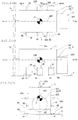
FIG. 1 shows an engine unit support structure.FIG. 1A is a plan view,FIG. 1B is a front view (as seen from a side of the engine unit), andFIG. 1C is a right side view (as seen from back of the engine unit). -
FIG. 2 shows the engine unit support structure.FIG. 2A is a plan view,FIG. 2B is a front view (as seen from a side of the engine unit), andFIG. 2C is a right side view (as seen from back of the engine unit). -
FIG. 3 shows a procedure for installing the engine unit support structure. - Hereinafter, the invention will be described based on preferred embodiments which do not intend to limit the scope of the claims of the present invention. Not all of the combinations of the features described in the embodiments are necessarily essential to the solutions presented by the invention.
- As shown in
FIG. 1 andFIG. 2 , an engineunit support structure 1 according to the first embodiment includes anengine unit 2, amount 3, and a plurality ofelastic support bodies 4. - For example, with an operating machine such as a construction machinery whose actuator is driven hydraulically, the
engine unit 2, as shown inFIG. 1 , is of a construction having a three-cylinder engine 22 which has acooling fan 21 for cooling the engine and ahydraulic pump 23 driven by theengine 22. And themount 3 is a vehicle frame constituting a mechanical floor of the operating machine, or a mount attached to the vehicle frame. - The
engine unit 2 is equipped with acooling fan 21 on one end side of the engine 22 (on one end side in the extension direction of a not-shown output shaft (crank shaft) of the engine 22) and thehydraulic pump 23 on the other end side of theengine 22, as shown inFIG. 1 andFIG. 2 , for instance. - It is to be noted that the description of the present embodiment will be given with one end side of the
engine 22 as the "front" side and the other end side of theengine 22 as the "rear" side. - The
elastic support bodies 4 may be elastic support bodies having columnar rubber members as columnar elastic bodies, for instance. - As shown in
FIG. 1 andFIG. 2 , theelastic support bodies 4, at a lower end as one end thereof, are each coupled to themount 3 as a vibration receiver via ajoint member 41, such as a bracket, provided on themount 3. At the same time, theelastic support bodies 4, at an upper end as the other end thereof, are each coupled to theengine unit 2 as a vibration generator via ajoint member 42, such as a bracket, provided on left andright sides engine unit 2. - The plurality of
elastic support bodies elastic support bodies central axis 22B of theengine unit 2 and astride avirtual plane 22D (seeFIG. 1A, FIG. 1C ,FIG. 2A, FIG. 2C ) including a rolling rotationcentral axis 22A of theengine unit 2 and two pairs of secondelastic support bodies virtual plane 22D. - The rolling rotation
central axis 22A of theengine unit 2 is an axis extending in a front-rear direction of theengine unit 2 which is a center of rotation when theengine unit 2 rotates and vibrates. - The pitching rotation
central axis 22B of theengine unit 2 is the axis extending in a left-right direction of theengine unit 2 which is a center of rotation when theengine unit 2 rotates and vibrates. - It is to be noted that
FIG. 1 andFIG. 2 illustrate the rolling rotationcentral axis 22A passing through a gravity center G of theengine unit 2 and the pitching rotationcentral axis 22B passing through the gravity center G of theengine unit 2. However, there are cases where the rolling rotationcentral axis 22A and the pitching rotationcentral axis 22B do not pass through the gravity center G of theengine unit 2. - As shown in
FIG. 1 andFIG. 2 , a pair of firstelastic support bodies right sides engine unit 2. At the same time, each of the pair of firstelastic support bodies central axis 22B of theengine unit 2, and more preferably orthogonal to the rolling rotationcentral axis 22A of theengine unit 2 and on avirtual plane 22E (seeFIG. 1B andFIG. 2B ) including the pitching rotationcentral axis 22B of theengine unit 2. - It is further preferable that the first
elastic support bodies 4A are disposed on the axis line of the pitching rotationcentral axis 22B. The firstelastic support bodies 4A being disposed on the axis line of the pitching rotationcentral axis 22B means that the firstelastic support bodies 4A are located in positions where the pitching rotationcentral axis 22B of theengine unit 2 passes. More preferably, the firstelastic support bodies 4A are disposed such that the pitching rotationcentral axis 22B of theengine unit 2 passes through the gravity center of the firstelastic support bodies 4A. This will improve the vibration absorption performance for the pitching vibration of low frequency peculiar to the three-cylinder engine 22. - In this case, a
mount 31 having a mounting surface higher than a mounting surface of themount 3 is to be provided. And the firstelastic support bodies 4A are to be mounted on the mounting surface of themount 31. - It is to be noted that, as shown in
FIG. 2 , the firstelastic support bodies 4A may be disposed on thevirtual plane 22E below the pitching rotationcentral axis 22B. In such a case, it is preferable that the gravity center of the firstelastic support bodies 4A is located directly underneath the pitching rotationcentral axis 22B. - Also, although not shown, the first
elastic support bodies 4A may be disposed on thevirtual plane 22E above the pitching rotationcentral axis 22B. In such a case, it is preferable that the gravity center of the firstelastic support bodies 4A is located directly above the pitching rotationcentral axis 22B. - Also, the pair of first
elastic support bodies central axis 22A of theengine unit 2 - As shown in
FIG. 1 andFIG. 2 , two pairs of secondelastic support bodies right sides engine unit 2. At the same time, they are disposed in positions farther from the pitching rotationcentral axis 22B of theengine unit 2 than the firstelastic support bodies 4A. - One pair of second
elastic support bodies central axis 22A of theengine unit 2. - Similarly, the other pair of second
elastic support bodies central axis 22A of theengine unit 2. - In other words, the engine
unit support structure 1 according to the first embodiment is installed such that the secondelastic support bodies 4B are located astride thevirtual plane 22D. Also, the firstelastic support bodies 4A are closer to the pitching rotationcentral axis 22B than the secondelastic support bodies 4B and astride thevirtual plane 22D. - With the engine
unit support structure 1 according to the first embodiment, a pair of firstelastic support bodies right sides engine unit 2. At the same time, the pair of firstelastic support bodies central axis 22B of theengine unit 2, and more preferably orthogonal to the rolling rotationcentral axis 22A of theengine unit 2 and on avirtual plane 22E including the pitching rotationcentral axis 22B of theengine unit 2. Further, two pairs of secondelastic support bodies right sides engine unit 2, and they are disposed in positions farther from the pitching rotationcentral axis 22B of theengine unit 2 than the firstelastic support bodies 4A. Hence, the provision of the pair of firstelastic support bodies engine unit 2 to be borne by each of the four secondelastic support bodies elastic support body 4B smaller. As a result, the engine unit support structure can excel in the vibration absorption performance for controlling the pitching vibration of low frequency peculiar to the three-cylinder engine 22. - In other words, a pair of first
elastic support bodies central axis 22B of theengine unit 2, and more preferably orthogonal to the rolling rotationcentral axis 22A of theengine unit 2 and on thevirtual plane 22E including the pitching rotationcentral axis 22B of theengine unit 2. Thus, the spring constant of the secondelastic support body 4B can be made smaller. Also, the influence of the pair of firstelastic support bodies cylinder engine 22 can be made smaller. As a result, the engineunit support structure 1 featuring superior vibration absorption performance for controlling the vibration of theengine unit 2 having a three-cylinder engine 22 can be provided. - A frequency of the pitching vibration occurring when the speed of the three-cylinder engine is 1200 rpm, for instance, is 20 Hz. With the engine unit support structure as disclosed in the above-described
Patent Document 1, it is difficult to control the pitching vibration of frequencies as low as 20 Hz. However, with the engineunit support structure 1 of the present embodiment, the pitching vibration of frequencies as low as 20 Hz can be controlled. - Also, if the pair of first
elastic support bodies under surface 20 of theengine unit 2, it is possible that the pair of firstelastic support bodies engine unit 2. According to the first embodiment, the pair of firstelastic support bodies under surface 20 of theengine unit 2, but along the left andright sides engine unit 2. Therefore, it becomes possible to locate the pair of firstelastic support bodies central axis 22B of theengine unit 2, which improves the vibration absorption performance for the pitching vibration. - Also, it becomes possible to use rubber of smaller spring constant as the second
elastic support bodies 4B. This will improve the vibration absorption performance. At the same time, the durability of the engineunit support structure 1 can be improved because the load of theengine unit 2 is borne by two firstelastic support bodies 4A and four secondelastic support bodies unit support structure 1 thus obtained excels in both vibration absorption performance and durability. - Also, the vibration absorption performance of the engine
unit support structure 1 can be further improved by using elastic support bodies equipped with columnar rubber members as the plurality ofelastic support bodies - Pre-compressed first
elastic support bodies 4A or firstelastic support bodies 4A formed with harder rubber than the secondelastic support bodies 4B may be used so that the distributed load of theengine unit 2 borne by each of the firstelastic support bodies 4A is greater than the distributed load of theengine unit 2 borne individually by the secondelastic support bodies engine unit 2 borne individually by the secondelastic support bodies elastic support bodies 4B. This will further improve the vibration absorption performance of the engineunit support structure 1 described in the first embodiment. At the same time, the durability of the engineunit support structure 1 can be further improved because the load of theengine unit 2 is borne by the firstelastic support bodies 4A and four secondelastic support bodies - The arrangement may be such that the first
elastic support bodies 4A whose vertical (direction in which theengine unit 2 is supported) spring constant is greater than the vertical spring constant of the secondelastic support body 4B is used so that the distributed load of theengine unit 2 borne by the firstelastic support body 4A is greater than the distributed load of theengine unit 2 borne individually by the secondelastic support bodies engine unit 2 borne by the firstelastic support body 4A is greater than the distributed load of theengine unit 2 borne individually by the secondelastic support bodies - For example, this may be realized by use of a columnar rubber body constituting the first
elastic support body 4A whose vertical spring constant is greater than the vertical spring constant of the columnar rubber body constituting the secondelastic support body 4B. - Also, the first
elastic support body 4A to be used may be one whose vertical (direction in which theengine unit 2 is supported) spring constant is greater than the spring constant in the direction intersecting with the vertical direction, that is, one whose vertical spring is hard and horizontal spring is soft with the stiffness ratio being 0.4 or below, for instance. This will further improve the vibration absorption performance of the engineunit support structure 1. - For example, a columnar rubber body constituting the first
elastic support body 4A whose stiffness ratio is 0.4 or below may be used. - That is, use of a vibration absorbing rubber which is hard in the vertical direction and soft in the horizontal direction as the first
elastic support bodies - Now a description is given of a method for mounting an engine unit to constitute the engine unit support structure described in the foregoing first to fourth embodiments.
- As shown in
FIG. 3 , the above-described two firstelastic support bodies 4A and four secondelastic support bodies elastic support bodies engine unit 2 is coupled to the firstelastic support bodies 4A and the secondelastic support bodies 4B from above the firstelastic support bodies 4A and the secondelastic support bodies 4B coupled to themount 3. At this time, the firstelastic support bodies 4A are placed higher than the secondelastic support bodies 4B (seeFIG. 3A ), when the load of theengine unit 2 is not acting on the firstelastic support bodies 4A and the secondelastic support bodies 4B, so that the load of theengine unit 2 acts on the first elastic support bodies before the second elastic support bodies. Then theengine unit 2 and the firstelastic support bodies 4A are coupled together, and theengine unit 2 and the secondelastic support bodies 4B are coupled together. By doing so, the load of theengine unit 2 is borne by the firstelastic support bodies 4A and the secondelastic support bodies 4B in a distributed manner (seeFIG. 3B ). In this manner, each of the firstelastic support bodies 4A bears more of the load of theengine unit 2. That is, as shown inFIG. 3B , a greater load F1 can be placed on the firstelastic support bodies 4A than the load F2 placed on each of the secondelastic support bodies 4B. Accordingly, it becomes possible to use rubber of a smaller spring constant as the secondelastic support bodies 4B. This will improve the vibration absorption performance of the engineunit support structure 1. At the same time, the durability of the engineunit support structure 1 can be further improved because the load of theengine unit 2 is borne by the firstelastic support bodies 4A and the four secondelastic support bodies - Also, by adjusting the installation positions of the first
elastic support bodies 4A, it becomes possible to equalize the distributed loads of theengine unit 2 to be borne by the four secondelastic support bodies unit support structure 1 excelling in both vibration absorption performance for pitching vibration and durability can be obtained easily. - Also, the first
elastic support bodies 4A having the vertical (direction in which theengine unit 2 is supported) spring constant equal or equivalent to the secondelastic support bodies 4B can produce the same effects as described above. In this case, the cost of theelastic support bodies 4 can be reduced because equal or equivalent firstelastic support bodies 4A and secondelastic support bodies 4B can be used. - It is to be noted that the first
elastic support bodies 4A whose vertical (direction in which theengine unit 2 is supported) spring constant is different from the secondelastic support bodies 4B can be used. - It is to be noted that the vibration absorption device as disclosed in Japanese Unexamined Patent Application Publication No.
2009-228770 elastic support bodies 4B. - That is, a pair of vibration absorption rubber structures equipped with bracket joints and bolt holes is sandwiched between a pair of plates. At the same time, one end of the bracket coupled to the bracket joint of the pair of vibration absorption rubber structures is coupled to the
engine unit 2 as a vibration generator or to themount 3 such as the vehicle frame as a vibration receiver. In this manner, a sandwich type vibration absorption device is used in which one of the pair of the plates is coupled to themount 3 such as the vehicle frame as a vibration receiver or to theengine unit 2 as a vibration generator. - The pair of vibration absorption rubber structures is each includes a cylinder having a bolt hole formed by a cylindrical space, a vibration absorption rubber joined by curing bond or the like to the outer periphery of the cylinder to surround the cylinder, and an annular member attached to the other end surface of the vibration absorption rubber located on the other end side of the cylinder with the central axis of the cylinder as the center thereof. The annular member, which is coaxial with the central axis of the cylinder as the central axis thereof, has a cylindrical portion with larger diameter than the cylinder and a flange extending outward from one end of the cylindrical portion. And the flange surface on one side of the flange is coupled to the other end surface of the vibration absorption rubber by curing bond or the like.
- The cylindrical portion of one vibration absorption rubber structure is inserted into the joint hole formed in the other end of the bracket from the other end side of the cylindrical portion of one vibration absorption rubber structure, and the cylindrical portion of the other vibration absorption rubber structure is also inserted from the other end side of the cylindrical portion of the other vibration absorption rubber structure. In this manner, the other ends of the respective cylinders of the pair of vibration absorption rubber structures and the other ends of the respective cylintrical portions are both placed opposite to each other, and the portion around the joint hole of the other end of the bracket is sandwiched between the other flange surfaces of the respective flanges of the pair of vibration absorption rubber structures. And one of the plates is placed on the end surface of the vibration absorption rubber located on one end side of the cylinder of one vibration absorption rubber structure. Also, the other of the plates is placed on the end surface of the vibration absorption rubber located on one end side of the cylinder of the other vibration absorption rubber structure. After this, bolts are inserted through the bolt hole in one of the plates, the bolt holes that are inner walls of each cylinder of the pair of vibration absorption rubber structures, and the bolt hole in the other of the plates, and nuts are attached to the threaded ends of the bolts protruding from the bolt holes in the other plate. Thus the vibration absorption device is formed.
- Then one end of the bracket of the vibration absorption device is coupled to the
engine unit 2, for instance. At the same time, the other plate of the vibration absorption device is coupled to themount 3. By doing so, the vibration absorption device can be made to function as the secondelastic support bodies 4B. - With the vibration absorption device as described above used as the second
elastic support bodies 4B, the secondelastic support bodies 4B play the role of a stopper when the vehicle body rebounds. This will prevent tensile force from being inputted to the firstelastic support bodies 4A, thus procucing an effect of improving the durability of the firstelastic support bodies 4A. - The second
elastic support bodies 4B may be of structures different from each other. - The
elastic support bodies 4 may use spring instead of rubber. - Also, the
joints 42 for the secondelastic support bodies 4B on theengine unit 2 may be located higher than thejoints 42 for the firstelastic support bodies 4A. - The engine
unit support structure 1 may be so arranged that more than one third elastic support bodies, instead of one of the pair of secondelastic support bodies elastic support bodies under surface 20 of theengine unit 2. - That is, the arrangement may be such that at least one pair of second
elastic support bodies 4B is installed in a position farther from the pitching rotationcentral axis 22B of theengine unit 2 than the firstelastic support bodies 4A and astride the above-mentionedvirtual plane 22D. - A pair of first
elastic support bodies elastic support bodies virtual plane 22D. However, it is not essential that the gravity center of each of the firstelastic support bodies - Similarly, a pair of second
elastic support bodies elastic support bodies virtual plane 22D. However, it is not essential that the gravity center of each of the secondelastic support bodies - The present invention is applicable to engine unit support structures and methods for mounting engine units of agricultural machinery, ships, and vehicles equipped with three-cylinder engines. For example, it is applicable to support structures for engine units equipped with an engine and a transmission or engine units with an engine only and methods for mounting such engine units.
- The engine unit support structure according to an embodiment of the present invention includes an engine unit having a three-cylinder engine, a mount for mounting the engine unit, and a plurality of elastic support bodies coupled to the engine unit and the mount, for supporting the engine unit. In the engine unit support structure, the plurality of elastic support bodies include a plurality of first elastic support bodies and a plurality of second elastic support bodies . And the second elastic support bodies are so disposed as to be orthogonal to a pitching rotation central axis of the engine unit and astride a virtual plane including a rolling rotation central axis of the engine unit, and the first elastic support bodies are disposed in positions closer to the pitching rotation central axis than the second elastic support bodies and astride the virtual plane. As a result, with the engine unit having a three-cylinder engine, distributed load to be borne by the second elastic support bodies can be reduced. Thus, an engine unit support structure excelling in vibration absorption performance for the pitching vibration can be provided.
- Also, the distributed load of the engine unit to be borne by each of the first elastic support bodies is greater than the distributed load of the engine unit to be borne by each of the second elastic support bodies. This will reduce the distributed load of the engine unit to be borne by each of the second elastic support bodies. And it becomes possible to use rubber of a smaller spring constant as the second elastic support bodies. This will further improve the vibration absorption performance for the pitching vibration of the three-cylinder engine . At the same time, the durability of the engine unit support structure can be further improved because the load of the engine unit is borne by the first elastic support bodies and the second elastic support bodies . That is, an engine unit support structure excelling in both vibration absorption performance for the pitching vibration and durability can be obtained.
- Also, the spring constants in the vertical direction of the first elastic support bodies and the second elastic support bodies are such that the vertical spring constant of the first elastic support bodies is greater than that of the second elastic support bodies. This makes it possible to arrange that the distributed load of the engine unit to be borne by the first elastic support body is greater than the distributed load of the engine unit to be borne by each of the second elastic support bodies. Hence, an engine unit support structure excelling in both vibration absorption performance for the pitching vibration and durability can be obtained.
- Also, the first elastic support bodies are so disposed as to be orthogonal to the rolling rotation central axis of the engine unit and on a virtual plane including the pitching rotation central axis of the engine unit. As a result, the vibration absorption performance for the pitching vibration is further improved.
- Also, a pair of first elastic support bodies so disposed as to be astride the virtual plane is arranged along the sides of the engine unit. As a result, it becomes possible to bring the pair of first elastic support bodies closer to the pitching rotation central axis of the engine unit, thus improving the vibration absorption performance for the pitching vibration.
- Moreover, according to a method for mounting an engine unit to constitute an engine unit support structure as described above, first elastic support bodies and second elastic support bodies are provided in such positions that a load of the engine unit is borne first by the first elastic support bodies then by the second elastic support bodies when the engine unit is coupled to the first elastic support bodies and the second elastic support bodies coupled to a mount from above the first elastic support bodies and the second elastic support bodies, and then the engine unit and the first elastic support bodies are coupled together and the engine unit and the second elastic support bodies are coupled together such that the load of the engine unit is borne by the first elastic support bodies and the second elastic support bodied in a distributed manner. As a result, a stable engine unit support structure excelling in both vibration absorption performance for pitching vibration and durability can be obtained easily.
-
- 1
- engine unit support structure
- 2
- engine unit
- 3
- mount
- 4A
- first elastic support body
- 4B
- second elastic support body
- 22
- engine
- 22A
- rolling rotation central axis
- 22B
- pitching rotation central axis
- 22D
- virtual plane
- 22E
- virtual plane
- 22S
- side of engine unit
Claims (6)
- An engine unit support structure comprising:an engine unit having a three-cylinder engine;a mount for mounting the engine unit; anda plurality of elastic support bodies coupled to the engine unit and the mount to support the engine unit,wherein the plurality of elastic support bodies include a plurality of first elastic support bodies and a plurality of second elastic support bodies, andwherein the second elastic support bodies are so disposed as to be orthogonal to a pitching rotation central axis of the engine unit and astride a virtual plane including a rolling rotation central axis of the engine unit, and the first elastic support bodies are disposed in a position closer to the pitching rotation central axis than the second elastic support bodies and astride the virtual plane.
- The engine unit support structure of claim 1, wherein a distributed load of the engine unit to be borne by each of the first elastic support bodies is greater than a distributed load of the engine unit to be borne by each of the second elastic support bodies.
- The engine unit support structure of claim 1 or claim 2, wherein a spring constant in a vertical direction of each of the first elastic support bodies is greater than that of each of the second elastic support bodies.
- The engine unit support structure of any of claims 1 to 3, wherein the first elastic support bodies are so disposed as to be orthogonal to the rolling rotation central axis of the engine unit and on the virtual plane including the pitching rotation central axis of the engine unit.
- The engine unit support structure of any of claims 1 to 4, wherein a pair of first elastic support bodies so disposed as to be astride the virtual plane is located along sides of the engine unit.
- A method for mounting an engine unit to constitute an engine unit support structure as recited in claim 2, the method comprising:providing first elastic support bodies and second elastic support bodies in such positions that a load of the engine unit is borne first by the first elastic support bodies then by the second elastic support bodies when coupling the engine unit to the first elastic support bodies and the second elastic support bodies coupled to a mount from above the first elastic support bodies and the second elastic support bodies; and thencoupling the engine unit and the first elastic support bodies together and coupling the engine unit and the second elastic support bodies together such that the load of the engine unit is borne by the first elastic support bodies and the second elastic support bodied in a distributed manner.
Applications Claiming Priority (2)
| Application Number | Priority Date | Filing Date | Title |
|---|---|---|---|
| JP2015157242A JP6616122B2 (en) | 2015-08-07 | 2015-08-07 | Engine device support structure and engine device installation method |
| PCT/JP2016/072684 WO2017026330A1 (en) | 2015-08-07 | 2016-08-02 | Engine device support structure and engine device installation method |
Publications (3)
| Publication Number | Publication Date |
|---|---|
| EP3332999A1 true EP3332999A1 (en) | 2018-06-13 |
| EP3332999A4 EP3332999A4 (en) | 2018-11-07 |
| EP3332999B1 EP3332999B1 (en) | 2022-04-13 |
Family
ID=57983159
Family Applications (1)
| Application Number | Title | Priority Date | Filing Date |
|---|---|---|---|
| EP16835027.0A Active EP3332999B1 (en) | 2015-08-07 | 2016-08-02 | Engine device support structure and engine device installation method |
Country Status (5)
| Country | Link |
|---|---|
| US (1) | US10300778B2 (en) |
| EP (1) | EP3332999B1 (en) |
| JP (1) | JP6616122B2 (en) |
| CN (1) | CN107848389B (en) |
| WO (1) | WO2017026330A1 (en) |
Families Citing this family (8)
| Publication number | Priority date | Publication date | Assignee | Title |
|---|---|---|---|---|
| US10850192B2 (en) | 2016-03-04 | 2020-12-01 | Sony Interactive Entertainment Inc. | Control apparatus and control program |
| JP6626576B2 (en) | 2016-07-21 | 2019-12-25 | 株式会社ソニー・インタラクティブエンタテインメント | Operation device and control system |
| WO2018020778A1 (en) | 2016-07-26 | 2018-02-01 | 株式会社ソニー・インタラクティブエンタテインメント | Information processing system, operation device, and method for controlling operation device |
| EP3493030B1 (en) | 2016-07-26 | 2021-06-23 | Sony Interactive Entertainment Inc. | Operation device and operation device control method |
| WO2019064518A1 (en) * | 2017-09-29 | 2019-04-04 | 株式会社ソニー・インタラクティブエンタテインメント | Operation device and control apparatus therefor |
| US11511185B2 (en) | 2017-10-27 | 2022-11-29 | Sony Interactive Entertainment Inc. | Operation device |
| CN111960240B (en) * | 2020-08-27 | 2025-07-01 | 湖南湘一环境科技有限公司 | Automatically controlled lifting device and garbage compactor |
| CN112060900B (en) * | 2020-10-10 | 2022-04-05 | 上海汽车集团股份有限公司 | Automobile, powertrain suspension system and its torsion rod |
Family Cites Families (11)
| Publication number | Priority date | Publication date | Assignee | Title |
|---|---|---|---|---|
| JPS59196751U (en) * | 1983-06-16 | 1984-12-27 | トヨタ自動車株式会社 | engine mounting equipment |
| JP2657319B2 (en) * | 1989-08-08 | 1997-09-24 | 本田技研工業株式会社 | Automobile power unit support device |
| JP3374655B2 (en) * | 1996-04-23 | 2003-02-10 | トヨタ自動車株式会社 | Method for supporting an engine / transmission assembly on a vehicle body and support structure for the assembly |
| JP3341638B2 (en) * | 1997-07-11 | 2002-11-05 | トヨタ自動車株式会社 | Powertrain suspension |
| US6708793B2 (en) * | 2001-05-11 | 2004-03-23 | General Motors Corporation | Double-isolated, symmetric, high-damped mount system |
| JP2005247249A (en) * | 2004-03-08 | 2005-09-15 | Hitachi Constr Mach Co Ltd | Engine support structure |
| JP4715190B2 (en) * | 2004-12-20 | 2011-07-06 | 日産自動車株式会社 | Vehicle engine mounting structure |
| US8042793B2 (en) * | 2006-09-06 | 2011-10-25 | Honda Motor Co., Ltd. | Solid engine mount |
| FR2942998B1 (en) * | 2009-03-16 | 2012-07-20 | Peugeot Citroen Automobiles Sa | DEVICE FOR THE SUSPENSION OF A POWER PLANT IN A VEHICLE BOX |
| BR112012012367B8 (en) | 2009-11-26 | 2023-01-17 | Nissan Motor | THREE CYLINDER ENGINE |
| DE102011079111A1 (en) * | 2011-07-14 | 2013-01-17 | Bayerische Motoren Werke Aktiengesellschaft | Aggregate attachment for drive unit mounted in engine of motor vehicle, has vibration-damping elements which are arranged in vertical axis with respect to longitudinal and transverse directions of vehicle |
-
2015
- 2015-08-07 JP JP2015157242A patent/JP6616122B2/en active Active
-
2016
- 2016-08-02 EP EP16835027.0A patent/EP3332999B1/en active Active
- 2016-08-02 US US15/744,169 patent/US10300778B2/en active Active
- 2016-08-02 CN CN201680045954.1A patent/CN107848389B/en active Active
- 2016-08-02 WO PCT/JP2016/072684 patent/WO2017026330A1/en not_active Ceased
Also Published As
| Publication number | Publication date |
|---|---|
| JP6616122B2 (en) | 2019-12-04 |
| EP3332999B1 (en) | 2022-04-13 |
| JP2017035945A (en) | 2017-02-16 |
| US10300778B2 (en) | 2019-05-28 |
| WO2017026330A1 (en) | 2017-02-16 |
| US20180208039A1 (en) | 2018-07-26 |
| CN107848389A (en) | 2018-03-27 |
| CN107848389B (en) | 2020-12-08 |
| EP3332999A4 (en) | 2018-11-07 |
Similar Documents
| Publication | Publication Date | Title |
|---|---|---|
| EP3332999B1 (en) | Engine device support structure and engine device installation method | |
| CN103895488B (en) | Power unit for multi-purpose vehicle | |
| JP5779033B2 (en) | Vibration isolator for vehicle | |
| JP5747270B2 (en) | Installation structure of important safety parts at the rear of the car | |
| RU2376134C1 (en) | Mixing machine for construction materials | |
| US20170028834A1 (en) | Split bushing torque strut isolator assembly | |
| JPWO2019198393A1 (en) | Anti-vibration device for unmanned aerial vehicles | |
| EP3065962A1 (en) | Torque roll axis mounting system for serial range extenders without a through-drive | |
| CN103375522B (en) | Isolated supporting tectosome | |
| RU2758728C2 (en) | Monoblock device for supporting power plant, containing intermediate support | |
| US10072386B1 (en) | Vibration system | |
| JP2004314945A (en) | Power train supporting device of forklift | |
| CN106061781B (en) | Engine device support construction and engine device setting method | |
| KR20160060598A (en) | Controller assembly and work machine cab | |
| KR20090129324A (en) | Devices for the installation of engines in the frames of agricultural or industrial utility vehicles | |
| US9951482B2 (en) | Vibration isolation for compactor | |
| CN101784811B (en) | Vibration dampers for aircraft cabins | |
| JP2015010690A (en) | Vibration reduction structure of pipeline and construction machine including the same | |
| CN108995523B (en) | Equipment support structure for motor vehicle | |
| JP2000128493A (en) | Industrial vehicles | |
| JP2014163391A (en) | Rotary machine installation base | |
| JP2016210343A (en) | Vibration isolation structure of construction machine | |
| CN208646534U (en) | Automotive shock absorber mounts and automotive shock absorbers | |
| CN209409784U (en) | Reducer assemblies, vehicle and rear suspension bracket | |
| EP1570721A1 (en) | Lawnmower |
Legal Events
| Date | Code | Title | Description |
|---|---|---|---|
| STAA | Information on the status of an ep patent application or granted ep patent |
Free format text: STATUS: THE INTERNATIONAL PUBLICATION HAS BEEN MADE |
|
| PUAI | Public reference made under article 153(3) epc to a published international application that has entered the european phase |
Free format text: ORIGINAL CODE: 0009012 |
|
| STAA | Information on the status of an ep patent application or granted ep patent |
Free format text: STATUS: REQUEST FOR EXAMINATION WAS MADE |
|
| 17P | Request for examination filed |
Effective date: 20180123 |
|
| AK | Designated contracting states |
Kind code of ref document: A1 Designated state(s): AL AT BE BG CH CY CZ DE DK EE ES FI FR GB GR HR HU IE IS IT LI LT LU LV MC MK MT NL NO PL PT RO RS SE SI SK SM TR |
|
| AX | Request for extension of the european patent |
Extension state: BA ME |
|
| A4 | Supplementary search report drawn up and despatched |
Effective date: 20181008 |
|
| RIC1 | Information provided on ipc code assigned before grant |
Ipc: B60K 5/12 20060101AFI20181001BHEP Ipc: F16M 7/00 20060101ALI20181001BHEP |
|
| DAV | Request for validation of the european patent (deleted) | ||
| DAX | Request for extension of the european patent (deleted) | ||
| GRAP | Despatch of communication of intention to grant a patent |
Free format text: ORIGINAL CODE: EPIDOSNIGR1 |
|
| STAA | Information on the status of an ep patent application or granted ep patent |
Free format text: STATUS: GRANT OF PATENT IS INTENDED |
|
| INTG | Intention to grant announced |
Effective date: 20211207 |
|
| GRAS | Grant fee paid |
Free format text: ORIGINAL CODE: EPIDOSNIGR3 |
|
| GRAA | (expected) grant |
Free format text: ORIGINAL CODE: 0009210 |
|
| STAA | Information on the status of an ep patent application or granted ep patent |
Free format text: STATUS: THE PATENT HAS BEEN GRANTED |
|
| AK | Designated contracting states |
Kind code of ref document: B1 Designated state(s): AL AT BE BG CH CY CZ DE DK EE ES FI FR GB GR HR HU IE IS IT LI LT LU LV MC MK MT NL NO PL PT RO RS SE SI SK SM TR |
|
| REG | Reference to a national code |
Ref country code: GB Ref legal event code: FG4D |
|
| REG | Reference to a national code |
Ref country code: CH Ref legal event code: EP |
|
| REG | Reference to a national code |
Ref country code: DE Ref legal event code: R096 Ref document number: 602016071125 Country of ref document: DE |
|
| REG | Reference to a national code |
Ref country code: IE Ref legal event code: FG4D |
|
| REG | Reference to a national code |
Ref country code: AT Ref legal event code: REF Ref document number: 1483133 Country of ref document: AT Kind code of ref document: T Effective date: 20220515 |
|
| REG | Reference to a national code |
Ref country code: GB Ref legal event code: 732E Free format text: REGISTERED BETWEEN 20220707 AND 20220713 |
|
| REG | Reference to a national code |
Ref country code: LT Ref legal event code: MG9D |
|
| REG | Reference to a national code |
Ref country code: NL Ref legal event code: MP Effective date: 20220413 |
|
| REG | Reference to a national code |
Ref country code: AT Ref legal event code: MK05 Ref document number: 1483133 Country of ref document: AT Kind code of ref document: T Effective date: 20220413 |
|
| REG | Reference to a national code |
Ref country code: DE Ref legal event code: R081 Ref document number: 602016071125 Country of ref document: DE Owner name: PROSPIRA CORPORATION, JP Free format text: FORMER OWNER: BRIDGESTONE CORPORATION, TOKYO, JP |
|
| PG25 | Lapsed in a contracting state [announced via postgrant information from national office to epo] |
Ref country code: NL Free format text: LAPSE BECAUSE OF FAILURE TO SUBMIT A TRANSLATION OF THE DESCRIPTION OR TO PAY THE FEE WITHIN THE PRESCRIBED TIME-LIMIT Effective date: 20220413 |
|
| PG25 | Lapsed in a contracting state [announced via postgrant information from national office to epo] |
Ref country code: SE Free format text: LAPSE BECAUSE OF FAILURE TO SUBMIT A TRANSLATION OF THE DESCRIPTION OR TO PAY THE FEE WITHIN THE PRESCRIBED TIME-LIMIT Effective date: 20220413 Ref country code: PT Free format text: LAPSE BECAUSE OF FAILURE TO SUBMIT A TRANSLATION OF THE DESCRIPTION OR TO PAY THE FEE WITHIN THE PRESCRIBED TIME-LIMIT Effective date: 20220816 Ref country code: NO Free format text: LAPSE BECAUSE OF FAILURE TO SUBMIT A TRANSLATION OF THE DESCRIPTION OR TO PAY THE FEE WITHIN THE PRESCRIBED TIME-LIMIT Effective date: 20220713 Ref country code: LT Free format text: LAPSE BECAUSE OF FAILURE TO SUBMIT A TRANSLATION OF THE DESCRIPTION OR TO PAY THE FEE WITHIN THE PRESCRIBED TIME-LIMIT Effective date: 20220413 Ref country code: HR Free format text: LAPSE BECAUSE OF FAILURE TO SUBMIT A TRANSLATION OF THE DESCRIPTION OR TO PAY THE FEE WITHIN THE PRESCRIBED TIME-LIMIT Effective date: 20220413 Ref country code: GR Free format text: LAPSE BECAUSE OF FAILURE TO SUBMIT A TRANSLATION OF THE DESCRIPTION OR TO PAY THE FEE WITHIN THE PRESCRIBED TIME-LIMIT Effective date: 20220714 Ref country code: FI Free format text: LAPSE BECAUSE OF FAILURE TO SUBMIT A TRANSLATION OF THE DESCRIPTION OR TO PAY THE FEE WITHIN THE PRESCRIBED TIME-LIMIT Effective date: 20220413 Ref country code: ES Free format text: LAPSE BECAUSE OF FAILURE TO SUBMIT A TRANSLATION OF THE DESCRIPTION OR TO PAY THE FEE WITHIN THE PRESCRIBED TIME-LIMIT Effective date: 20220413 Ref country code: BG Free format text: LAPSE BECAUSE OF FAILURE TO SUBMIT A TRANSLATION OF THE DESCRIPTION OR TO PAY THE FEE WITHIN THE PRESCRIBED TIME-LIMIT Effective date: 20220713 Ref country code: AT Free format text: LAPSE BECAUSE OF FAILURE TO SUBMIT A TRANSLATION OF THE DESCRIPTION OR TO PAY THE FEE WITHIN THE PRESCRIBED TIME-LIMIT Effective date: 20220413 |
|
| PG25 | Lapsed in a contracting state [announced via postgrant information from national office to epo] |
Ref country code: RS Free format text: LAPSE BECAUSE OF FAILURE TO SUBMIT A TRANSLATION OF THE DESCRIPTION OR TO PAY THE FEE WITHIN THE PRESCRIBED TIME-LIMIT Effective date: 20220413 Ref country code: PL Free format text: LAPSE BECAUSE OF FAILURE TO SUBMIT A TRANSLATION OF THE DESCRIPTION OR TO PAY THE FEE WITHIN THE PRESCRIBED TIME-LIMIT Effective date: 20220413 Ref country code: LV Free format text: LAPSE BECAUSE OF FAILURE TO SUBMIT A TRANSLATION OF THE DESCRIPTION OR TO PAY THE FEE WITHIN THE PRESCRIBED TIME-LIMIT Effective date: 20220413 Ref country code: IS Free format text: LAPSE BECAUSE OF FAILURE TO SUBMIT A TRANSLATION OF THE DESCRIPTION OR TO PAY THE FEE WITHIN THE PRESCRIBED TIME-LIMIT Effective date: 20220813 |
|
| REG | Reference to a national code |
Ref country code: DE Ref legal event code: R097 Ref document number: 602016071125 Country of ref document: DE |
|
| PG25 | Lapsed in a contracting state [announced via postgrant information from national office to epo] |
Ref country code: SM Free format text: LAPSE BECAUSE OF FAILURE TO SUBMIT A TRANSLATION OF THE DESCRIPTION OR TO PAY THE FEE WITHIN THE PRESCRIBED TIME-LIMIT Effective date: 20220413 Ref country code: SK Free format text: LAPSE BECAUSE OF FAILURE TO SUBMIT A TRANSLATION OF THE DESCRIPTION OR TO PAY THE FEE WITHIN THE PRESCRIBED TIME-LIMIT Effective date: 20220413 Ref country code: RO Free format text: LAPSE BECAUSE OF FAILURE TO SUBMIT A TRANSLATION OF THE DESCRIPTION OR TO PAY THE FEE WITHIN THE PRESCRIBED TIME-LIMIT Effective date: 20220413 Ref country code: EE Free format text: LAPSE BECAUSE OF FAILURE TO SUBMIT A TRANSLATION OF THE DESCRIPTION OR TO PAY THE FEE WITHIN THE PRESCRIBED TIME-LIMIT Effective date: 20220413 Ref country code: DK Free format text: LAPSE BECAUSE OF FAILURE TO SUBMIT A TRANSLATION OF THE DESCRIPTION OR TO PAY THE FEE WITHIN THE PRESCRIBED TIME-LIMIT Effective date: 20220413 Ref country code: CZ Free format text: LAPSE BECAUSE OF FAILURE TO SUBMIT A TRANSLATION OF THE DESCRIPTION OR TO PAY THE FEE WITHIN THE PRESCRIBED TIME-LIMIT Effective date: 20220413 |
|
| PLBE | No opposition filed within time limit |
Free format text: ORIGINAL CODE: 0009261 |
|
| STAA | Information on the status of an ep patent application or granted ep patent |
Free format text: STATUS: NO OPPOSITION FILED WITHIN TIME LIMIT |
|
| 26N | No opposition filed |
Effective date: 20230116 |
|
| PG25 | Lapsed in a contracting state [announced via postgrant information from national office to epo] |
Ref country code: MC Free format text: LAPSE BECAUSE OF FAILURE TO SUBMIT A TRANSLATION OF THE DESCRIPTION OR TO PAY THE FEE WITHIN THE PRESCRIBED TIME-LIMIT Effective date: 20220413 Ref country code: AL Free format text: LAPSE BECAUSE OF FAILURE TO SUBMIT A TRANSLATION OF THE DESCRIPTION OR TO PAY THE FEE WITHIN THE PRESCRIBED TIME-LIMIT Effective date: 20220413 |
|
| REG | Reference to a national code |
Ref country code: CH Ref legal event code: PL |
|
| PG25 | Lapsed in a contracting state [announced via postgrant information from national office to epo] |
Ref country code: LU Free format text: LAPSE BECAUSE OF NON-PAYMENT OF DUE FEES Effective date: 20220802 Ref country code: LI Free format text: LAPSE BECAUSE OF NON-PAYMENT OF DUE FEES Effective date: 20220831 Ref country code: CH Free format text: LAPSE BECAUSE OF NON-PAYMENT OF DUE FEES Effective date: 20220831 |
|
| REG | Reference to a national code |
Ref country code: BE Ref legal event code: MM Effective date: 20220831 |
|
| REG | Reference to a national code |
Ref country code: DE Ref legal event code: R082 Ref document number: 602016071125 Country of ref document: DE |
|
| PG25 | Lapsed in a contracting state [announced via postgrant information from national office to epo] |
Ref country code: SI Free format text: LAPSE BECAUSE OF FAILURE TO SUBMIT A TRANSLATION OF THE DESCRIPTION OR TO PAY THE FEE WITHIN THE PRESCRIBED TIME-LIMIT Effective date: 20220413 |
|
| PG25 | Lapsed in a contracting state [announced via postgrant information from national office to epo] |
Ref country code: IE Free format text: LAPSE BECAUSE OF NON-PAYMENT OF DUE FEES Effective date: 20220802 Ref country code: FR Free format text: LAPSE BECAUSE OF NON-PAYMENT OF DUE FEES Effective date: 20220831 |
|
| PG25 | Lapsed in a contracting state [announced via postgrant information from national office to epo] |
Ref country code: BE Free format text: LAPSE BECAUSE OF NON-PAYMENT OF DUE FEES Effective date: 20220831 |
|
| PG25 | Lapsed in a contracting state [announced via postgrant information from national office to epo] |
Ref country code: IT Free format text: LAPSE BECAUSE OF FAILURE TO SUBMIT A TRANSLATION OF THE DESCRIPTION OR TO PAY THE FEE WITHIN THE PRESCRIBED TIME-LIMIT Effective date: 20220413 |
|
| PG25 | Lapsed in a contracting state [announced via postgrant information from national office to epo] |
Ref country code: HU Free format text: LAPSE BECAUSE OF FAILURE TO SUBMIT A TRANSLATION OF THE DESCRIPTION OR TO PAY THE FEE WITHIN THE PRESCRIBED TIME-LIMIT; INVALID AB INITIO Effective date: 20160802 |
|
| PG25 | Lapsed in a contracting state [announced via postgrant information from national office to epo] |
Ref country code: MK Free format text: LAPSE BECAUSE OF FAILURE TO SUBMIT A TRANSLATION OF THE DESCRIPTION OR TO PAY THE FEE WITHIN THE PRESCRIBED TIME-LIMIT Effective date: 20220413 Ref country code: CY Free format text: LAPSE BECAUSE OF FAILURE TO SUBMIT A TRANSLATION OF THE DESCRIPTION OR TO PAY THE FEE WITHIN THE PRESCRIBED TIME-LIMIT Effective date: 20220413 |
|
| PG25 | Lapsed in a contracting state [announced via postgrant information from national office to epo] |
Ref country code: TR Free format text: LAPSE BECAUSE OF FAILURE TO SUBMIT A TRANSLATION OF THE DESCRIPTION OR TO PAY THE FEE WITHIN THE PRESCRIBED TIME-LIMIT Effective date: 20220413 |
|
| PG25 | Lapsed in a contracting state [announced via postgrant information from national office to epo] |
Ref country code: MT Free format text: LAPSE BECAUSE OF FAILURE TO SUBMIT A TRANSLATION OF THE DESCRIPTION OR TO PAY THE FEE WITHIN THE PRESCRIBED TIME-LIMIT Effective date: 20220413 |
|
| PG25 | Lapsed in a contracting state [announced via postgrant information from national office to epo] |
Ref country code: BG Free format text: LAPSE BECAUSE OF FAILURE TO SUBMIT A TRANSLATION OF THE DESCRIPTION OR TO PAY THE FEE WITHIN THE PRESCRIBED TIME-LIMIT Effective date: 20220413 |
|
| PG25 | Lapsed in a contracting state [announced via postgrant information from national office to epo] |
Ref country code: BG Free format text: LAPSE BECAUSE OF FAILURE TO SUBMIT A TRANSLATION OF THE DESCRIPTION OR TO PAY THE FEE WITHIN THE PRESCRIBED TIME-LIMIT Effective date: 20220413 |
|
| PGFP | Annual fee paid to national office [announced via postgrant information from national office to epo] |
Ref country code: DE Payment date: 20250820 Year of fee payment: 10 |
|
| PGFP | Annual fee paid to national office [announced via postgrant information from national office to epo] |
Ref country code: GB Payment date: 20250821 Year of fee payment: 10 |