EP3332989A1 - Tire for running on rough terrain - Google Patents
Tire for running on rough terrain Download PDFInfo
- Publication number
- EP3332989A1 EP3332989A1 EP17202003.4A EP17202003A EP3332989A1 EP 3332989 A1 EP3332989 A1 EP 3332989A1 EP 17202003 A EP17202003 A EP 17202003A EP 3332989 A1 EP3332989 A1 EP 3332989A1
- Authority
- EP
- European Patent Office
- Prior art keywords
- tire
- crown
- blocks
- block
- axial direction
- Prior art date
- Legal status (The legal status is an assumption and is not a legal conclusion. Google has not performed a legal analysis and makes no representation as to the accuracy of the status listed.)
- Granted
Links
Images


Classifications
-
- B—PERFORMING OPERATIONS; TRANSPORTING
- B60—VEHICLES IN GENERAL
- B60C—VEHICLE TYRES; TYRE INFLATION; TYRE CHANGING; CONNECTING VALVES TO INFLATABLE ELASTIC BODIES IN GENERAL; DEVICES OR ARRANGEMENTS RELATED TO TYRES
- B60C11/00—Tyre tread bands; Tread patterns; Anti-skid inserts
- B60C11/03—Tread patterns
- B60C11/11—Tread patterns in which the raised area of the pattern consists only of isolated elements, e.g. blocks
-
- B—PERFORMING OPERATIONS; TRANSPORTING
- B60—VEHICLES IN GENERAL
- B60C—VEHICLE TYRES; TYRE INFLATION; TYRE CHANGING; CONNECTING VALVES TO INFLATABLE ELASTIC BODIES IN GENERAL; DEVICES OR ARRANGEMENTS RELATED TO TYRES
- B60C11/00—Tyre tread bands; Tread patterns; Anti-skid inserts
- B60C11/03—Tread patterns
- B60C11/0302—Tread patterns directional pattern, i.e. with main rolling direction
-
- B—PERFORMING OPERATIONS; TRANSPORTING
- B60—VEHICLES IN GENERAL
- B60C—VEHICLE TYRES; TYRE INFLATION; TYRE CHANGING; CONNECTING VALVES TO INFLATABLE ELASTIC BODIES IN GENERAL; DEVICES OR ARRANGEMENTS RELATED TO TYRES
- B60C11/00—Tyre tread bands; Tread patterns; Anti-skid inserts
- B60C11/03—Tread patterns
- B60C11/0311—Patterns comprising tread lugs arranged parallel or oblique to the axis of rotation
-
- B—PERFORMING OPERATIONS; TRANSPORTING
- B60—VEHICLES IN GENERAL
- B60C—VEHICLE TYRES; TYRE INFLATION; TYRE CHANGING; CONNECTING VALVES TO INFLATABLE ELASTIC BODIES IN GENERAL; DEVICES OR ARRANGEMENTS RELATED TO TYRES
- B60C11/00—Tyre tread bands; Tread patterns; Anti-skid inserts
- B60C11/03—Tread patterns
- B60C11/0311—Patterns comprising tread lugs arranged parallel or oblique to the axis of rotation
- B60C2011/0313—Patterns comprising tread lugs arranged parallel or oblique to the axis of rotation directional type
-
- B—PERFORMING OPERATIONS; TRANSPORTING
- B60—VEHICLES IN GENERAL
- B60C—VEHICLE TYRES; TYRE INFLATION; TYRE CHANGING; CONNECTING VALVES TO INFLATABLE ELASTIC BODIES IN GENERAL; DEVICES OR ARRANGEMENTS RELATED TO TYRES
- B60C2200/00—Tyres specially adapted for particular applications
- B60C2200/14—Tyres specially adapted for particular applications for off-road use
Definitions
- the present invention relates to a tire for running on rough terrain capable of exerting large traction on muddy roads.
- Patent Literature 1 Japanese Unexamined Patent Application Publication No. 2016-60347 has proposed a tire for running on rough terrain provided with axially-long crown blocks and middle blocks in order to obtain large traction.
- the present invention was made in view of the above, and a primary object thereof is to provide a tire for running on rough terrain capable of exerting large traction on muddy roads.
- a tire comprises a tread portion bound with an intended tire rotational direction and comprising a row of crown blocks arranged on a tire equator and a pair of rows of middle blocks arranged in a tire circumferential direction on both sides of the row of the crown blocks, wherein each of the crown blocks and the middle blocks has an axially-elongated shape in which a length thereof in a tire axial direction is longer than a length thereof in the tire circumferential direction, a ground contacting surface of each of the crown blocks has a crown front edge positioned on a heel-side in the tire rotational direction, the crown front edge comprises a most concave portion positioned at the most toe-side thereof in the tire rotational direction and a pair of inclined edges extending from the most concave portion toward both sides thereof in the tire axial direction and toward the heel-side in the tire rotational direction, an inclination angle of each of the inclined edges is in a range of from 10 to 45 degrees with respect to the tire axial direction, a
- the middle front edge is inclined at an angle in a range of from 10 to 45 degrees with respect to the tire axial direction.
- a pair of the crown block and the middle block adjacent to each other in the tire circumferential direction are arranged so that an imaginary straight line obtained by connecting a centroid of the ground contacting surface of the crown block and a centroid of the ground contacting surface of the middle block is inclined at an angle in a range of from 20 to 45 degrees with respect to the tire axial direction.
- a gap in the tire axial direction between the crown block and the middle block is in a range of from 0.05 to 0.10 times a tread development width, and a gap in the tire circumferential direction between the crown block and the middle block is in a range of from 0.50 to 1.00 times the gap in the tire axial direction.
- a width in the tire axial direction of the ground contacting surface of each of the crown blocks is in a range of from 0.25 to 0.35 times the tread development width
- a width in the tire axial direction of the ground contacting surface of each of the middle blocks is in a range of from 0.10 to 0.15 times the tread development width
- each of the middle blocks comprises a substantially rectangular block main body and a convex portion protruding toward the toe-side from the block main body.
- the convex portion is provided axially outside a center position in the tire axial direction of the ground contacting surface of the middle block.
- the middle front edge is concave toward the toe-side.
- each of the middle blocks has a middle rear edge, and the middle rear edge is concave toward the heel-side.
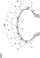
- Fig. 1 is a lateral cross-sectional view of a tire for running on rough terrain (hereinafter may be simply referred to as "tire") 1 according to an embodiment of the present invention in a standard state.
- Fig. 2 is a development view of a tread portion 2 of the tire 1 showing a tread pattern thereof.
- Fig. 1 is a cross-sectional view taken along A-A line of Fig. 2 .
- the "standard state” is a state in which the tire 1 is mounted on a standard rim (not shown), inflated to a standard pressure, and loaded with no tire load.
- a standard rim not shown
- dimensions and the like of various parts of the tire are values measured in the standard state unless otherwise noted.
- the "standard rim” is a wheel rim specified for the concerned tire by a standard included in a standardization system on which the tire is based, for example, the "normal wheel rim” in JATMA, "Design Rim” in TRA, and “Measuring Rim” in ETRTO.
- the "standard pressure” is air pressure specified for the concerned tire by a standard included in a standardization system on which the tire is based, for example, the “maximum air pressure” in JATMA, maximum value listed in the "TIRE LOAD LIMITS AT VARIOUS COLD INFLATION PRESSURES" table in TRA, and "INFLATION PRESSURE” in ETRTO.
- the tire 1 in this embodiment is a tire for a motorcycle for running on rough terrain, and is used, for example, for motocross competition.
- an outer surface thereof is curved in an arc shape protruding outwardly in a tire radial direction.
- the tire of the present invention is not limited to a tire for a motorcycle, but may be used for a three-wheel buggy or a 4WD-car, for example.
- the tire 1 in this embodiment is provided with, for example, a carcass 6 and a belt layer 7. Known configurations are appropriately applied to these.
- the tread portion 2 has a directional pattern bound with an intended rotational direction (R).
- the rotational direction (R) is indicated by a letter or a symbol on at least one of the sidewall portions 3 (shown in Fig. 1 ), for example.
- the tread portion 2 is divided into a crown region (Cr), a pair of middle regions (Mi), and a pair of shoulder regions (Sh), for example.
- the crown region (Cr) is a region having a width of 1/3 of a tread development width (TWe) with a tire equator (C) in a center thereof.
- the shoulder regions (Sh) are regions each having a width of 1/6 of the tread development width (TWe) and extending from each of tread edges (Te) toward the tire equator (C).
- Each of the middle regions (Mi) is a region between the crown region (Cr) and each of the shoulder regions (Sh).
- the tread development width (TWe) is a distance in a tire axial direction between tread edges (Te) when the tread portion 2 is developed into a plane.
- the "tread edges (Te)” means axially outermost edges of blocks arranged axially outermost among the blocks provided in the tread portion 2.
- the tread portion 2 is provided with a row of crown blocks 10 arranged along the tire equator (C), a pair of rows of middle blocks 11 arranged in a tire circumferential direction on both sides in the tire axial direction of the row of the crown blocks 10, and a pair of rows of shoulder blocks 12 each arranged in the tire circumferential direction on an axially outer side of the corresponding row of the middle blocks 11.
- each of the crown blocks 10 for example, the entire block is provided in the crown region (Cr) and at least a part thereof extends across the tire equator (C).
- a center portion thereof in the tire axial direction is located on the tire equator (C).
- each of the crown blocks 10 in this embodiment has a ground contacting surface that is line symmetrical with respect to the tire equator (C) with a centroid (10c) of the ground contacting surface located on the tire equator (C).
- a centroid (11c) of a ground contacting surface thereof is located within the middle regions (Mi).
- a part of each of the middle blocks 11 in this embodiment extends across a boundary (not shown) between one of the middle regions (Mi) and its adjacent one of the shoulder regions (Sh).
- the centroids (11c) of the ground contacting surfaces of the middle blocks 11 in this embodiment are provided, for example, in regions axially outside the center positions in the tire axial direction of the middle regions (Mi).
- a distance L1 in the tire axial direction (that is, a distance along the outer surface of the tread portion 2, the same applies below) between the centroid (11c) of the ground contacting surface of each of the middle blocks 11 and the tire equator (C) is, for example, in a range of from 0.25 to 0.35 times the tread development width (TWe).
- a centroid (12c) of a ground contacting surface thereof is located within the shoulder regions (Sh).
- the centroids (12c) of the ground contacting surfaces of the shoulder blocks 12 in this embodiment are provided, for example, in regions axially outside the center positions in the tire axial direction of the shoulder regions (Sh). More specifically, a distance L2 in the tire axial direction between the centroid (12c) of the ground contacting surface of each of the shoulder blocks 12 and the tire equator (C) is, for example, in a range of from 0.40 to 0.48 times the tread development width (TWe).
- Each of the crown blocks 10 and the middle blocks 11 has an axially-elongated shape in which a length thereof in the tire axial direction is larger than a length thereof in the tire circumferential direction.
- the crown blocks 10 and the middle blocks 11 configured as such can exert large traction upon shearing mud on a road surface during running on a muddy road.
- a ratio W2/W1 of a length W2 in the tire circumferential direction and a width W1 in the tire axial direction of the ground contacting surface of each of the crown blocks 10 is in a range of from 0.25 to 0.45, for example. Further, it is preferred that the width W1 in the tire axial direction of the ground contacting surface of each of the crown blocks 10 is in a range of from 0.25 to 0.35 times the tread development width (TWe), for example.
- TWe tread development width
- a ratio W4/W3 of a length W4 in the tire circumferential direction and a width w3 in the tire axial direction of the ground contacting surface of each of the middle blocks 11 is in a range of from 0.50 to 0.90, for example. Further, it is preferred that the width W3 in the tire axial direction of the ground contacting surface of each of the middle blocks 11 is smaller than 1/2 of the width W1 of the crown block 10, for example. More specifically, it is preferred that the w3 is in a range of from 0.10 to 0.15 times the tread development width (TWe).
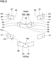
- Fig. 3 shows an enlarged partial view of the crown blocks 10 and the middle blocks 11.
- a ground contacting surface (10s) of each of the crown blocks 10 comprises, for example, a first surface 13 disposed on one side of a center position of the ground contacting surface (10s) in the tire axial direction and a second surface 14 disposed on the other side of the center position and connected with the first surface 13.
- Each of the first surface 13 and the second surface 14 is formed in an axially-elongated shape in which a width thereof in the tire circumferential direction is constant in a longitudinal direction of the ground contacting surface in this embodiment.
- each of the first surface 13 and the second surface 14 is, for example, formed in a rectangular shape, and formed in a parallelogram shape in this embodiment.
- the first surface 13 and the second surface 14 are configured in line symmetry.
- the ground contacting surfaces of the crown blocks 10 are not limited to such a configuration.
- each of the crown blocks 10 includes a crown front edge 15 positioned on a heel-side in the rotational direction (R) (hereinafter may be simply referred to as "heel-side”) and a crown rear edge 16 positioned on a toe-side in the rotational direction (R) (hereinafter, may be simply referred to as "toe-side”), and a pair of crown side edges 17 extending therebetween.
- the crown front edge 15 is concave toward the toe-side and includes a most concave portion 18 positioned at the most toe-side.
- the most concave portion 18 in this embodiment is provided, for example, at the center position in the tire axial direction of the block.
- the crown front edge is not limited to such a configuration, and the most concave portion 18 may be provided, for example, at a position different from the center position.
- the crown front edge 15 includes a pair of inclined edges 20 each extending from the most concave portion 18 positioned at the most toe-side toward both sides of the most concave portion 18 in the tire axial direction and toward the heel-side.
- the inclined edges 20 include an inclined edge (20a) on one side and an inclined edge (20b) on the other side in the tire axial direction, and they are inclined in opposite directions to each other.
- Each of the inclined edges (20a) and (20b) in this embodiment extends straight from the most concave portion 18 to respective ends in the tire axial direction of the crown front edge 15, for example. That is, the entire crown front edge 15 is composed of a pair of the inclined edges 20. Thereby, the pair of inclined edges 20 is configured, for example, in a V-shape that is concave toward the toe-side.
- the inclined edge (20a) on one side and the inclined edge (20b) on the other side in this embodiment are formed line-symmetrically. However, they are not limited to such a configuration and the inclined edge (20a) and the inclined edge (20b) may have shapes and lengths different from each other.
- each of the crown blocks 10 has block walls extending radially inwardly from each of the inclined edges 20 on the heel-side.
- the block walls disposed on the heel-side include two surfaces inclined in opposite directions to each other on both sides of the most concave portion 18, and are concave toward the toe-side.
- An angle ⁇ 1 of each of the inclined edges (20a) and (20b) with respect to the tire axial direction is in a range of from 10 to 45 degrees.
- the crown blocks 10 configured as such can scrape mud toward the center of the block and then can shear it by the inclined edges 20 during running on rough terrain. Thereby, mud does not escape in the left and right sides of the inclined edges, therefore, larger traction can be expected.
- the angle ⁇ 1 is preferably not larger than 30 degrees, more preferably not larger than 20 degrees. Thereby, it is possible that large traction is obtained even on a relatively hard road surface.
- the crown rear edge 16 extends along the crown front edge 15, for example. Thereby, the crown rear edge 16 is configured in a v-shape convex toward the toe-side. As a more preferred embodiment, the crown rear edge 16 and the crown front edge 15 extend in parallel with each other. Thereby, each of the crown blocks 10 extends in the tire axial direction with a constant width, therefore, partial damage of the blocks during running is suppressed.
- the crown side edges 17 are disposed on both sides in the tire axial direction of the crown block 10 and extend in the tire circumferential direction between the crown front edge 15 and the crown rear edge 16.
- the crown side edges 17 in this embodiment extend straight in the tire circumferential direction.
- the crown side edges 17 configured as such is helpful for shearing mud in the tire axial direction, therefore, it is possible that cornering performance on rough terrain is improved.
- a plurality of the middle blocks 11 is provided in the tire circumferential direction at same pitches as the crown blocks 10.
- each of the middle blocks 11 is, for example, formed in a rectangular shape, and in this embodiment, a width thereof in the tire circumferential direction is constant in a lateral direction of the block.
- the ground contacting surface of each of the middle blocks 11 in this embodiment is configured in a parallelogram shape.
- each of the middle blocks 11 includes a middle front edge 21 positioned on the heel-side, a middle rear edge 22 positioned on the toe-side, and a pair of middle side edges 23 extending between them.
- the middle front edge 21 extends axially outwardly and is inclined to the heel-side.
- each of the middle blocks 11 has a block wall extending radially inwardly from the middle front edge 21 on the heel-side.
- the block wall on the heel-side is inclined in the same direction as the middle front edge 21.
- the middle blocks 11 configured as such guide mud and the like to sides of the crown blocks 10 by the middle front edges 21 during running on muddy roads. Thereby, it is possible that the crown blocks 10 shear more mud, therefore, larger traction is obtained.
- the middle front edge 21 in this embodiment extends straight in its entirety, for example. Thereby, it is possible that more mud is guided toward the crown blocks 10.
- an angle ⁇ 2 of the middle front edge 21 with respect to the tire axial direction is in a range of from 10 to 45 degrees, for example.
- the angle ⁇ 2 is preferably not greater than 30 degrees, more preferably not greater than 20 degrees.
- the middle rear edge 22 is inclined to the same direction as the middle front edge 21, for example. It is preferred that the middle rear edge 22 extends along the middle front edge 21. As a more preferred embodiment, the middle rear edge 22 in its entirety in this embodiment extends in parallel with the middle front edge 21.
- the middle side edges 23 are arranged on both sides in the tire axial direction of each of the middle blocks 11. Each of the middle side edges 23 extends in the tire circumferential direction between the middle front edge 21 and the middle rear edge 22, and extends straight along the tire circumferential direction in this embodiment.
- the middle side edges 23 configured as such are helpful for shearing mud in the tire axial direction, therefore, it is possible that the cornering performance on rough terrain is improved.
- an imaginary straight line 25 obtained by connecting the centroid (10c) of the ground contacting surface of the crown block 10 and the centroid (11c) of the ground contacting surface of the middle block 11 is inclined in the same direction as the middle front edge 21. It is preferred that the pair of the crown block 10 and the middle block 11 is arranged so that the imaginary straight line 25 is inclined at an angle ⁇ 3 in a range of from 20 to 45 degrees with respect to the tire axial direction.
- the angle ⁇ 3 is preferably not more than 40 degrees, more preferably not more than 30 degrees.
- the crown block 10 and the middle block 11 are arranged so as to have a gap L3 in tire axial direction between the ground contacting surfaces thereof, for example.
- a gap L3 in tire axial direction between the ground contacting surfaces thereof, for example.
- an area obtained by projecting the ground contacting surface of the crown block 10 in the tire circumferential direction does not overlap the ground contacting surface of the middle block 11.
- the gap L3 is in a range of from 0.05 to 0.10 times the tread development width (TWe), for example.
- the centroids of the ground contacting surfaces of the crown block 10 and the middle block 11 in this embodiment are misaligned in the tire circumferential direction, for example.
- the crown block 10 and the middle block 11 in this embodiment are misaligned in their entirety in the tire circumferential direction. That is, the crown block 10 and the middle block 11 are arranged so as to have a gap L4 in the tire circumferential direction between the ground contacting surfaces thereof, and an area obtained by projecting the ground contacting surface of the crown block 10 along the tire axial direction does not overlap the ground contacting surface of the middle block 11.
- the gap L4 is preferably not smaller than 0.50 times the above described gap L3 in the tire axial direction, more preferably not smaller than 0.65 times the gap L3, and preferably not more than 1.00 times the gap L3, more preferably not more than 0.85 times the gap L3.
- a plurality of the shoulder blocks 12 is provided in the tire circumferential direction at the same pitches as the middle blocks 11.
- each of the shoulder blocks 12 is formed in a rectangular shape, for example, and in this embodiment, a length thereof in the tire circumferential direction is constant in the lateral direction of the block.
- the ground contacting surface of each of the shoulder blocks 12 in this embodiment is configured in a parallelogram shape.
- a ratio w6/w5 of a length W6 in the tire circumferential direction and a length W5 in the tire axial direction of the ground contacting surface of each of the shoulder blocks 12 is in a range of from 0.90 to 1.30, for example. Further, it is preferred that the length W5 in the tire axial direction of the ground contacting surface of the shoulder block 12 is smaller than the width W3 in the tire axial direction of the ground contacting surface of the middle block 11, for example, and specifically, it is preferred that the length W5 is in a range of from 0.05 to 0.10 times the tread development width (TWe).
- each of the shoulder blocks 12 has a shoulder front edge 27 located on the heel-side thereof.
- the shoulder front edge 27 is inclined in the same direction as the middle front edge 21, for example. It is preferred that the shoulder front edge 27 is inclined at the same angle as the middle front edge 21 with respect to the tire axial direction.
- the shoulder front edge 27 in this embodiment is provided at a position where the middle front edge 21 is extended in its longitudinal direction.
- the middle block 11 and the shoulder block 12 are arranged so as to have a gap L5 in tire axial direction between the ground contacting surfaces thereof, for example.
- a gap L5 in tire axial direction between the ground contacting surfaces thereof, for example.
- an area obtained by projecting the ground contacting surface of the middle block 11 in the tire circumferential direction does not overlap the ground contacting surface of the shoulder block 12.
- the gap L5 is in a range of from 0.05 to 0.10 times the tread development width (TWe), for example.
- the centroid (11c) of the ground contacting surface of the middle block 11 and the centroid (12c) of the ground contacting surface of the shoulder block 12 are misaligned in the tire circumferential direction.
- the centroid (12c) of the shoulder block 12 is positioned on the heel-side of the centroid (11c) of the middle block 11.
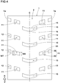
- Fig 4 shows a development view of the tread portion 2 according to second embodiment of the present invention
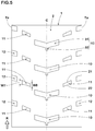
- Fig. 5 shows a development view of the tread portion 2 according to third embodiment of the present invention.
- the embodiments shown in Figs. 4 and 5 have the same configuration as the above-described first embodiment except for the differences described below.
- Figs. 4 and 5 the same reference numbers are given to the configurations common to the above-described first embodiment.
- the crown front edge 15 in this embodiment is formed in an arc shape concave toward the toe-side.
- the crown rear edge 16 is formed in an arc shape convex toward the toe side.
- the crown front edge 15 and the crown rear edge 16 extend in parallel with each other.
- Each of the crown blocks 10 configured as such is deformed in its entirety when shearing mud, therefore, it is possible that partial damage of the block is suppressed.
- each of the middle blocks 11 in this embodiment includes a substantially rectangular block main body 28 and a convex portion 29 protruding toward the toe-side from the block main body 28.
- the middle block 11 configured as such, deformation in the tire circumferential direction of the block is suppressed by the convex portions 29, therefore, it is possible that large reaction force is obtained when the block shears mud.
- the convex portion 29 is provided axially outside the center position in the tire axial direction of the ground contacting surface of the middle block 11. More preferably, the convex portion 29 is provided at an outer end in the tire axial direction of the middle block 11, and a part of the convex portion 29 constitutes a part of the middle side edges 23. Thereby, axially inner part of each of the middle blocks 11 is relatively easy to deform, therefore, it is possible that the middle blocks 11 guide mud toward the crown blocks 10 more effectively.
- each of the crown blocks 10 in this embodiment includes an axially-elongated block main body 31 and a convex portion 32 protruding toward the toe-side from the block main body 31.
- the convex portion 32 is provided, for example, at the center position in the tire axial direction of the crown block 10.
- the convex portions 32 configured as such are helpful for suppressing deformation in the tire circumferential direction of the crown blocks 10.
- the middle front edge 21 in this embodiment is concave toward the toe-side. Thereby, it is possible that the middle blocks 11 provide larger reaction force in the tire circumferential direction when shearing mud.
- the middle rear edge 22 in this embodiment is concave toward the heel-side. Therefore, mud positioned on the toe-side of the middle block 11 is easy to move in the tire axial direction, therefore, it is possible that the motorcycle is easy to lean when running on muddy roads.
- a length W7 in the tire circumferential direction of an outer end in the tire axial direction of each of the middle blocks 11 is larger than a length W8 in the tire circumferential direction of an inner end in the tire axial direction of each of the middle blocks 11.
- Tires for running on rough terrain, to be mounted on a rear wheel of a test vehicle, having the basic structure shown in Figs. 2 , 4 , or 5 were made by way of test according to the specifications listed in Table 1.
- a tire having the crown front edges extending straight in the tire axial direction as shown in Fig. 6 is made by way of test. Then each of the test tires was tested for the traction performance.
- Common specifications and test methods of the test tires are as follows.
- Test vehicle motorcycle for motocross competition with displacement of 450 cc
- a test rider drove the above-mentioned test vehicle on a soft road surface fully covered with mud containing a lot of water, a medium road surface including mixture of a road surface covered with the above mud and dry rough terrain, and a sandy road surface, and the test driver evaluated the traction performance of each of the test tires by the driver's feeling during the test drive.
- the results are indicated by an evaluation point based on Reference 1 being 100, wherein the larger the numerical value, the better the traction performance.
Landscapes
- Engineering & Computer Science (AREA)
- Mechanical Engineering (AREA)
- Tires In General (AREA)
Abstract
Description
- The present invention relates to a tire for running on rough terrain capable of exerting large traction on muddy roads.
- For example, Japanese Unexamined Patent Application Publication No.
2016-60347 - However, in the tire disclosed in
Patent Literature 1, mud scraped by crown blocks when they contact the ground easily moves in lateral directions during running on muddy roads, therefore, there is room for further improvement of traction. - The present invention was made in view of the above, and a primary object thereof is to provide a tire for running on rough terrain capable of exerting large traction on muddy roads.
- In one aspect of the present invention, a tire comprises a tread portion bound with an intended tire rotational direction and comprising a row of crown blocks arranged on a tire equator and a pair of rows of middle blocks arranged in a tire circumferential direction on both sides of the row of the crown blocks, wherein each of the crown blocks and the middle blocks has an axially-elongated shape in which a length thereof in a tire axial direction is longer than a length thereof in the tire circumferential direction, a ground contacting surface of each of the crown blocks has a crown front edge positioned on a heel-side in the tire rotational direction, the crown front edge comprises a most concave portion positioned at the most toe-side thereof in the tire rotational direction and a pair of inclined edges extending from the most concave portion toward both sides thereof in the tire axial direction and toward the heel-side in the tire rotational direction, an inclination angle of each of the inclined edges is in a range of from 10 to 45 degrees with respect to the tire axial direction, a ground contacting surface of each of the middle blocks has a middle front edge positioned on the heel-side in the tire rotational direction, and the middle front edge extends axially outwardly and is inclined to the heel-side.
- In another aspect of the invention, it is preferred that the middle front edge is inclined at an angle in a range of from 10 to 45 degrees with respect to the tire axial direction.
- In another aspect of the invention, it is preferred that a pair of the crown block and the middle block adjacent to each other in the tire circumferential direction are arranged so that an imaginary straight line obtained by connecting a centroid of the ground contacting surface of the crown block and a centroid of the ground contacting surface of the middle block is inclined at an angle in a range of from 20 to 45 degrees with respect to the tire axial direction.
- In another aspect of the invention, it is preferred that in a pair of the crown block and the middle block adjacent to each other in the tire circumferential direction, a gap in the tire axial direction between the crown block and the middle block is in a range of from 0.05 to 0.10 times a tread development width, and a gap in the tire circumferential direction between the crown block and the middle block is in a range of from 0.50 to 1.00 times the gap in the tire axial direction.
- In another aspect of the invention, it is preferred that a width in the tire axial direction of the ground contacting surface of each of the crown blocks is in a range of from 0.25 to 0.35 times the tread development width, and a width in the tire axial direction of the ground contacting surface of each of the middle blocks is in a range of from 0.10 to 0.15 times the tread development width.
- In another aspect of the invention, it is preferred that the ground contacting surface of each of the middle blocks comprises a substantially rectangular block main body and a convex portion protruding toward the toe-side from the block main body.
- In another aspect of the invention, it is preferred that the convex portion is provided axially outside a center position in the tire axial direction of the ground contacting surface of the middle block.
- In another aspect of the invention, it is preferred that the middle front edge is concave toward the toe-side.
- In another aspect of the invention, it is preferred that the ground contacting surface of each of the middle blocks has a middle rear edge, and the middle rear edge is concave toward the heel-side.
-
-
Fig. 1 is a lateral cross-sectional view of a tire for running on rough terrain according to one embodiment of the present invention. -
Fig. 2 is a development view showing a tread pattern of a tread portion ofFig. 1 . -
Fig. 3 is an enlarged partial view of crown blocks and middle blocks. -
Fig. 4 is a development view of the tread portion of a tire for running on rough terrain according to second embodiment of the present invention. -
Fig. 5 is a development view of the tread portion of a tire for running on rough terrain according to third embodiment of the present invention. -
Fig. 6 is a development view of the tread portion of a tire for running on rough terrain according toreference 1. - An embodiment of the present invention will now be described in conjunction with accompanying drawings.
-
Fig. 1 is a lateral cross-sectional view of a tire for running on rough terrain (hereinafter may be simply referred to as "tire") 1 according to an embodiment of the present invention in a standard state.Fig. 2 is a development view of atread portion 2 of thetire 1 showing a tread pattern thereof.Fig. 1 is a cross-sectional view taken along A-A line ofFig. 2 . - The "standard state" is a state in which the
tire 1 is mounted on a standard rim (not shown), inflated to a standard pressure, and loaded with no tire load. In this specification, dimensions and the like of various parts of the tire are values measured in the standard state unless otherwise noted. - The "standard rim" is a wheel rim specified for the concerned tire by a standard included in a standardization system on which the tire is based, for example, the "normal wheel rim" in JATMA, "Design Rim" in TRA, and "Measuring Rim" in ETRTO.
- The "standard pressure" is air pressure specified for the concerned tire by a standard included in a standardization system on which the tire is based, for example, the "maximum air pressure" in JATMA, maximum value listed in the "TIRE LOAD LIMITS AT VARIOUS COLD INFLATION PRESSURES" table in TRA, and "INFLATION PRESSURE" in ETRTO.
- As shown in
Fig. 1 , thetire 1 in this embodiment is a tire for a motorcycle for running on rough terrain, and is used, for example, for motocross competition. Thereby, in the lateral cross-section of thetread portion 2 of thetire 1 in this embodiment, an outer surface thereof is curved in an arc shape protruding outwardly in a tire radial direction. However, the tire of the present invention is not limited to a tire for a motorcycle, but may be used for a three-wheel buggy or a 4WD-car, for example. - The
tire 1 in this embodiment is provided with, for example, acarcass 6 and abelt layer 7. Known configurations are appropriately applied to these. - As shown in
Fig. 2 , thetread portion 2 has a directional pattern bound with an intended rotational direction (R). The rotational direction (R) is indicated by a letter or a symbol on at least one of the sidewall portions 3 (shown inFig. 1 ), for example. - The
tread portion 2 is divided into a crown region (Cr), a pair of middle regions (Mi), and a pair of shoulder regions (Sh), for example. - The crown region (Cr) is a region having a width of 1/3 of a tread development width (TWe) with a tire equator (C) in a center thereof.
The shoulder regions (Sh) are regions each having a width of 1/6 of the tread development width (TWe) and extending from each of tread edges (Te) toward the tire equator (C).
Each of the middle regions (Mi) is a region between the crown region (Cr) and each of the shoulder regions (Sh). - The tread development width (TWe) is a distance in a tire axial direction between tread edges (Te) when the
tread portion 2 is developed into a plane. The "tread edges (Te)" means axially outermost edges of blocks arranged axially outermost among the blocks provided in thetread portion 2. - The
tread portion 2 is provided with a row ofcrown blocks 10 arranged along the tire equator (C), a pair of rows ofmiddle blocks 11 arranged in a tire circumferential direction on both sides in the tire axial direction of the row of thecrown blocks 10, and a pair of rows ofshoulder blocks 12 each arranged in the tire circumferential direction on an axially outer side of the corresponding row of themiddle blocks 11. - In each of the
crown blocks 10, for example, the entire block is provided in the crown region (Cr) and at least a part thereof extends across the tire equator (C). In each of thecrown blocks 10, for example, a center portion thereof in the tire axial direction is located on the tire equator (C). As a preferred embodiment, each of thecrown blocks 10 in this embodiment has a ground contacting surface that is line symmetrical with respect to the tire equator (C) with a centroid (10c) of the ground contacting surface located on the tire equator (C). - In each of the
middle blocks 11, for example, a centroid (11c) of a ground contacting surface thereof is located within the middle regions (Mi). A part of each of themiddle blocks 11 in this embodiment extends across a boundary (not shown) between one of the middle regions (Mi) and its adjacent one of the shoulder regions (Sh). The centroids (11c) of the ground contacting surfaces of themiddle blocks 11 in this embodiment are provided, for example, in regions axially outside the center positions in the tire axial direction of the middle regions (Mi). More specifically, a distance L1 in the tire axial direction (that is, a distance along the outer surface of thetread portion 2, the same applies below) between the centroid (11c) of the ground contacting surface of each of themiddle blocks 11 and the tire equator (C) is, for example, in a range of from 0.25 to 0.35 times the tread development width (TWe). - In each of the
shoulder blocks 12, for example, a centroid (12c) of a ground contacting surface thereof is located within the shoulder regions (Sh). The centroids (12c) of the ground contacting surfaces of theshoulder blocks 12 in this embodiment are provided, for example, in regions axially outside the center positions in the tire axial direction of the shoulder regions (Sh). More specifically, a distance L2 in the tire axial direction between the centroid (12c) of the ground contacting surface of each of theshoulder blocks 12 and the tire equator (C) is, for example, in a range of from 0.40 to 0.48 times the tread development width (TWe). - Each of the
crown blocks 10 and themiddle blocks 11 has an axially-elongated shape in which a length thereof in the tire axial direction is larger than a length thereof in the tire circumferential direction. Thecrown blocks 10 and themiddle blocks 11 configured as such can exert large traction upon shearing mud on a road surface during running on a muddy road. - It is preferred that a ratio W2/W1 of a length W2 in the tire circumferential direction and a width W1 in the tire axial direction of the ground contacting surface of each of the
crown blocks 10 is in a range of from 0.25 to 0.45, for example. Further, it is preferred that the width W1 in the tire axial direction of the ground contacting surface of each of thecrown blocks 10 is in a range of from 0.25 to 0.35 times the tread development width (TWe), for example.
Thecrown blocks 10 configured as such have sufficient rigidity in the tire circumferential direction, therefore, it is possible that large traction is exerted under various road surface conditions. - It is preferred that a ratio W4/W3 of a length W4 in the tire circumferential direction and a width w3 in the tire axial direction of the ground contacting surface of each of the
middle blocks 11 is in a range of from 0.50 to 0.90, for example. Further, it is preferred that the width W3 in the tire axial direction of the ground contacting surface of each of themiddle blocks 11 is smaller than 1/2 of the width W1 of thecrown block 10, for example. More specifically, it is preferred that the w3 is in a range of from 0.10 to 0.15 times the tread development width (TWe). -
Fig. 3 shows an enlarged partial view of thecrown blocks 10 and themiddle blocks 11. As shown inFig. 3 , a ground contacting surface (10s) of each of the crown blocks 10 comprises, for example, afirst surface 13 disposed on one side of a center position of the ground contacting surface (10s) in the tire axial direction and asecond surface 14 disposed on the other side of the center position and connected with thefirst surface 13. Each of thefirst surface 13 and thesecond surface 14 is formed in an axially-elongated shape in which a width thereof in the tire circumferential direction is constant in a longitudinal direction of the ground contacting surface in this embodiment. Further, each of thefirst surface 13 and thesecond surface 14 is, for example, formed in a rectangular shape, and formed in a parallelogram shape in this embodiment. As a more preferred embodiment, thefirst surface 13 and thesecond surface 14 are configured in line symmetry. However, the ground contacting surfaces of the crown blocks 10 are not limited to such a configuration. - The ground contacting surface of each of the crown blocks 10 includes a
crown front edge 15 positioned on a heel-side in the rotational direction (R) (hereinafter may be simply referred to as "heel-side") and a crownrear edge 16 positioned on a toe-side in the rotational direction (R) (hereinafter, may be simply referred to as "toe-side"), and a pair of crown side edges 17 extending therebetween. - The
crown front edge 15 is concave toward the toe-side and includes a mostconcave portion 18 positioned at the most toe-side. The mostconcave portion 18 in this embodiment is provided, for example, at the center position in the tire axial direction of the block. However, the crown front edge is not limited to such a configuration, and the mostconcave portion 18 may be provided, for example, at a position different from the center position. - The
crown front edge 15 includes a pair ofinclined edges 20 each extending from the mostconcave portion 18 positioned at the most toe-side toward both sides of the mostconcave portion 18 in the tire axial direction and toward the heel-side. The inclined edges 20 include an inclined edge (20a) on one side and an inclined edge (20b) on the other side in the tire axial direction, and they are inclined in opposite directions to each other. - Each of the inclined edges (20a) and (20b) in this embodiment extends straight from the most
concave portion 18 to respective ends in the tire axial direction of thecrown front edge 15, for example. That is, the entirecrown front edge 15 is composed of a pair of the inclined edges 20. Thereby, the pair ofinclined edges 20 is configured, for example, in a V-shape that is concave toward the toe-side. - The inclined edge (20a) on one side and the inclined edge (20b) on the other side in this embodiment are formed line-symmetrically. However, they are not limited to such a configuration and the inclined edge (20a) and the inclined edge (20b) may have shapes and lengths different from each other.
- With the
inclined edges 20 configured as such, each of the crown blocks 10 has block walls extending radially inwardly from each of the inclined edges 20 on the heel-side. The block walls disposed on the heel-side include two surfaces inclined in opposite directions to each other on both sides of the mostconcave portion 18, and are concave toward the toe-side. - An angle θ1 of each of the inclined edges (20a) and (20b) with respect to the tire axial direction is in a range of from 10 to 45 degrees. The crown blocks 10 configured as such can scrape mud toward the center of the block and then can shear it by the
inclined edges 20 during running on rough terrain. Thereby, mud does not escape in the left and right sides of the inclined edges, therefore, larger traction can be expected. - The angle θ1 is preferably not larger than 30 degrees, more preferably not larger than 20 degrees. Thereby, it is possible that large traction is obtained even on a relatively hard road surface.
- The crown
rear edge 16 extends along thecrown front edge 15, for example. Thereby, the crownrear edge 16 is configured in a v-shape convex toward the toe-side. As a more preferred embodiment, the crownrear edge 16 and thecrown front edge 15 extend in parallel with each other. Thereby, each of the crown blocks 10 extends in the tire axial direction with a constant width, therefore, partial damage of the blocks during running is suppressed. - The crown side edges 17 are disposed on both sides in the tire axial direction of the
crown block 10 and extend in the tire circumferential direction between thecrown front edge 15 and the crownrear edge 16. The crown side edges 17 in this embodiment extend straight in the tire circumferential direction. The crown side edges 17 configured as such is helpful for shearing mud in the tire axial direction, therefore, it is possible that cornering performance on rough terrain is improved. - For example, a plurality of the middle blocks 11 is provided in the tire circumferential direction at same pitches as the crown blocks 10.
- The ground contacting surface of each of the middle blocks 11 is, for example, formed in a rectangular shape, and in this embodiment, a width thereof in the tire circumferential direction is constant in a lateral direction of the block. As a preferred embodiment, the ground contacting surface of each of the middle blocks 11 in this embodiment is configured in a parallelogram shape.
- The ground contacting surface of each of the middle blocks 11 includes a middle
front edge 21 positioned on the heel-side, a middlerear edge 22 positioned on the toe-side, and a pair of middle side edges 23 extending between them. - The middle
front edge 21 extends axially outwardly and is inclined to the heel-side. Thereby, each of the middle blocks 11 has a block wall extending radially inwardly from the middlefront edge 21 on the heel-side. The block wall on the heel-side is inclined in the same direction as the middlefront edge 21. - The middle blocks 11 configured as such guide mud and the like to sides of the crown blocks 10 by the middle front edges 21 during running on muddy roads.
Thereby, it is possible that the crown blocks 10 shear more mud, therefore, larger traction is obtained. - The middle
front edge 21 in this embodiment extends straight in its entirety, for example. Thereby, it is possible that more mud is guided toward the crown blocks 10. - It is preferred that an angle θ2 of the middle
front edge 21 with respect to the tire axial direction is in a range of from 10 to 45 degrees, for example. In order to exert large traction under various road surface conditions, the angle θ2 is preferably not greater than 30 degrees, more preferably not greater than 20 degrees. - The middle
rear edge 22 is inclined to the same direction as the middlefront edge 21, for example. It is preferred that the middlerear edge 22 extends along the middlefront edge 21. As a more preferred embodiment, the middlerear edge 22 in its entirety in this embodiment extends in parallel with the middlefront edge 21. - The middle side edges 23 are arranged on both sides in the tire axial direction of each of the middle blocks 11. Each of the middle side edges 23 extends in the tire circumferential direction between the middle
front edge 21 and the middlerear edge 22, and extends straight along the tire circumferential direction in this embodiment.
The middle side edges 23 configured as such are helpful for shearing mud in the tire axial direction, therefore, it is possible that the cornering performance on rough terrain is improved. - In a pair of the
crown block 10 and themiddle block 11 adjacent in the tire circumferential direction, an imaginarystraight line 25 obtained by connecting the centroid (10c) of the ground contacting surface of thecrown block 10 and the centroid (11c) of the ground contacting surface of themiddle block 11 is inclined in the same direction as the middlefront edge 21. It is preferred that the pair of thecrown block 10 and themiddle block 11 is arranged so that the imaginarystraight line 25 is inclined at an angle θ3 in a range of from 20 to 45 degrees with respect to the tire axial direction. By such arrangement of the blocks, it is possible that a lot of mud is guided toward the crown blocks 10, therefore, excellent traction performance is obtained. - In order to exert large traction under various road surface conditions, the angle θ3 is preferably not more than 40 degrees, more preferably not more than 30 degrees.
- As shown in
Fig. 2 , thecrown block 10 and themiddle block 11 are arranged so as to have a gap L3 in tire axial direction between the ground contacting surfaces thereof, for example. In other words, an area obtained by projecting the ground contacting surface of thecrown block 10 in the tire circumferential direction does not overlap the ground contacting surface of themiddle block 11. It is preferred that the gap L3 is in a range of from 0.05 to 0.10 times the tread development width (TWe), for example. By such arrangement of the crown blocks 10 and the middle blocks 11, it is possible that clogging of mud between the blocks is suppressed. - The centroids of the ground contacting surfaces of the
crown block 10 and themiddle block 11 in this embodiment are misaligned in the tire circumferential direction, for example. As a preferred embodiment, thecrown block 10 and themiddle block 11 in this embodiment are misaligned in their entirety in the tire circumferential direction.
That is, thecrown block 10 and themiddle block 11 are arranged so as to have a gap L4 in the tire circumferential direction between the ground contacting surfaces thereof, and an area obtained by projecting the ground contacting surface of thecrown block 10 along the tire axial direction does not overlap the ground contacting surface of themiddle block 11. - The gap L4 is preferably not smaller than 0.50 times the above described gap L3 in the tire axial direction, more preferably not smaller than 0.65 times the gap L3, and preferably not more than 1.00 times the gap L3, more preferably not more than 0.85 times the gap L3. By such arrangement of the crown blocks 10 and the middle blocks 11, it is possible that the middle blocks 11 guide a lot of mud toward the crown blocks 10, therefore, it is possible that clogging of mud is suppressed.
- For example, a plurality of the shoulder blocks 12 is provided in the tire circumferential direction at the same pitches as the middle blocks 11.
- The ground contacting surface of each of the shoulder blocks 12 is formed in a rectangular shape, for example, and in this embodiment, a length thereof in the tire circumferential direction is constant in the lateral direction of the block. As a preferred embodiment, the ground contacting surface of each of the shoulder blocks 12 in this embodiment is configured in a parallelogram shape.
- It is preferred that a ratio w6/w5 of a length W6 in the tire circumferential direction and a length W5 in the tire axial direction of the ground contacting surface of each of the shoulder blocks 12 is in a range of from 0.90 to 1.30, for example. Further, it is preferred that the length W5 in the tire axial direction of the ground contacting surface of the
shoulder block 12 is smaller than the width W3 in the tire axial direction of the ground contacting surface of themiddle block 11, for example, and specifically, it is preferred that the length W5 is in a range of from 0.05 to 0.10 times the tread development width (TWe). - The ground contacting surface of each of the shoulder blocks 12 has a
shoulder front edge 27 located on the heel-side thereof. Theshoulder front edge 27 is inclined in the same direction as the middlefront edge 21, for example. It is preferred that theshoulder front edge 27 is inclined at the same angle as the middlefront edge 21 with respect to the tire axial direction. As a further preferred embodiment, theshoulder front edge 27 in this embodiment is provided at a position where the middlefront edge 21 is extended in its longitudinal direction. Thereby, it is possible that the shoulder blocks 12 and the middle blocks 11 shear mud together as one body, therefore, excellent traction performance is obtained. - The
middle block 11 and theshoulder block 12 are arranged so as to have a gap L5 in tire axial direction between the ground contacting surfaces thereof, for example. In other words, an area obtained by projecting the ground contacting surface of themiddle block 11 in the tire circumferential direction does not overlap the ground contacting surface of theshoulder block 12. It is preferred that the gap L5 is in a range of from 0.05 to 0.10 times the tread development width (TWe), for example. By such arrangement of the middle blocks 11 and the shoulder blocks 12, it is possible that clogging of mud is suppressed while exerting the above described effects. - A projection area in the tire axial direction of the ground contacting surface of the
middle block 11 in this embodiment overlaps the ground contacting surface of theshoulder block 12. On the other hand, the centroid (11c) of the ground contacting surface of themiddle block 11 and the centroid (12c) of the ground contacting surface of theshoulder block 12 are misaligned in the tire circumferential direction. Specifically, the centroid (12c) of theshoulder block 12 is positioned on the heel-side of the centroid (11c) of themiddle block 11. Thereby, the shoulder blocks 12 guide mud toward the middle blocks 11, therefore, it is possible that the traction performance during cornering is improved. -
Fig 4 shows a development view of thetread portion 2 according to second embodiment of the present invention andFig. 5 shows a development view of thetread portion 2 according to third embodiment of the present invention. The embodiments shown inFigs. 4 and5 have the same configuration as the above-described first embodiment except for the differences described below. InFigs. 4 and5 , the same reference numbers are given to the configurations common to the above-described first embodiment. - As shown in
Fig. 4 , thecrown front edge 15 in this embodiment is formed in an arc shape concave toward the toe-side. Similarly, the crownrear edge 16 is formed in an arc shape convex toward the toe side. As a preferred embodiment, thecrown front edge 15 and the crownrear edge 16 extend in parallel with each other. Each of the crown blocks 10 configured as such is deformed in its entirety when shearing mud, therefore, it is possible that partial damage of the block is suppressed. - The ground contacting surface of each of the middle blocks 11 in this embodiment includes a substantially rectangular block
main body 28 and aconvex portion 29 protruding toward the toe-side from the blockmain body 28. In themiddle block 11 configured as such, deformation in the tire circumferential direction of the block is suppressed by theconvex portions 29, therefore, it is possible that large reaction force is obtained when the block shears mud. - It is preferred that the
convex portion 29 is provided axially outside the center position in the tire axial direction of the ground contacting surface of themiddle block 11. More preferably, theconvex portion 29 is provided at an outer end in the tire axial direction of themiddle block 11, and a part of theconvex portion 29 constitutes a part of the middle side edges 23. Thereby, axially inner part of each of the middle blocks 11 is relatively easy to deform, therefore, it is possible that the middle blocks 11 guide mud toward the crown blocks 10 more effectively. - As shown in
Fig. 5 , the ground contacting surface of each of the crown blocks 10 in this embodiment includes an axially-elongated blockmain body 31 and aconvex portion 32 protruding toward the toe-side from the blockmain body 31. Theconvex portion 32 is provided, for example, at the center position in the tire axial direction of thecrown block 10. Theconvex portions 32 configured as such are helpful for suppressing deformation in the tire circumferential direction of the crown blocks 10. - It is preferred that the middle
front edge 21 in this embodiment is concave toward the toe-side. Thereby, it is possible that the middle blocks 11 provide larger reaction force in the tire circumferential direction when shearing mud. - Further, it is preferred that the middle
rear edge 22 in this embodiment is concave toward the heel-side. Thereby, mud positioned on the toe-side of themiddle block 11 is easy to move in the tire axial direction, therefore, it is possible that the motorcycle is easy to lean when running on muddy roads. - In the embodiments of
Figs. 4 and5 , it is preferred that a length W7 in the tire circumferential direction of an outer end in the tire axial direction of each of the middle blocks 11 is larger than a length W8 in the tire circumferential direction of an inner end in the tire axial direction of each of the middle blocks 11.
Thereby, axially inner part of each of the middle blocks 11 is easy to deform, therefore, it is possible that mud is surely guided to the crown blocks 10. - while detailed description has been made of the tire for running on rough terrain as embodiments of the present invention, the present invention can be embodied in various forms without being limited to the illustrated embodiments.
- Tires for running on rough terrain, to be mounted on a rear wheel of a test vehicle, having the basic structure shown in
Figs. 2 ,4 , or5 were made by way of test according to the specifications listed in Table 1. Asreference 1, a tire having the crown front edges extending straight in the tire axial direction as shown inFig. 6 is made by way of test. Then each of the test tires was tested for the traction performance. Common specifications and test methods of the test tires are as follows. - Test vehicle: motorcycle for motocross competition with displacement of 450 cc
- Tire size: 110/90-19
- Rim size: 2.15x19
- Tire pressure: 80 kPa
- Test methods are as follows.
- A test rider drove the above-mentioned test vehicle on a soft road surface fully covered with mud containing a lot of water, a medium road surface including mixture of a road surface covered with the above mud and dry rough terrain, and a sandy road surface, and the test driver evaluated the traction performance of each of the test tires by the driver's feeling during the test drive. The results are indicated by an evaluation point based on
Reference 1 being 100, wherein the larger the numerical value, the better the traction performance. - Test results are shown in Table 1.


- As is clear from Table 1, it was confirmed that the tires as the Examples exerted excellent traction performance on each of the road surfaces.
Claims (9)
- A tire for running on rough terrain comprising:a tread portion bound with an intended tire rotational direction and comprising
a row of crown blocks arranged on a tire equator and
a pair of rows of middle blocks arranged in a tire circumferential direction on both sides of the row of the crown blocks, whereineach of the crown blocks and the middle blocks has an axially-elongated shape in which a length thereof in a tire axial direction is longer than a length thereof in the tire circumferential direction,a ground contacting surface of each of the crown blocks has a crown front edge positioned on a heel-side in the tire rotational direction,the crown front edge comprises
a most concave portion positioned at the most toe-side thereof in the tire rotational direction and
a pair of inclined edges extending from the most concave portion toward both sides thereof in the tire axial direction and toward the heel-side in the tire rotational direction,an inclination angle of each of the inclined edges is in a range of from 10 to 45 degrees with respect to the tire axial direction,a ground contacting surface of each of the middle blocks has a middle front edge positioned on the heel-side in the tire rotational direction, andthe middle front edge extends axially outwardly and is inclined to the heel-side. - The tire for running on rough terrain according to claim 1, wherein
the middle front edge is inclined at an angle in a range of from 10 to 45 degrees with respect to the tire axial direction. - The tire for running on rough terrain according to claim 1 or 2, wherein
a pair of the crown block and the middle block adjacent to each other in the tire circumferential direction are arranged so that an imaginary straight line obtained by connecting a centroid of the ground contacting surface of the crown block and a centroid of the ground contacting surface of the middle block is inclined at an angle in a range of from 20 to 45 degrees with respect to the tire axial direction. - The tire for running on rough terrain according to any one of claims 1 to 3, wherein
in a pair of the crown block and the middle block adjacent to each other in the tire circumferential direction,
a gap in the tire axial direction between the crown block and the middle block is in a range of from 0.05 to 0.10 times a tread development width, and
a gap in the tire circumferential direction between the crown block and the middle block is in a range of from 0.50 to 1.00 times the gap in the tire axial direction. - The tire for running on rough terrain according to any one of claims 1 to 4, wherein
a width in the tire axial direction of the ground contacting surface of each of the crown blocks is in a range of from 0.25 to 0.35 times the tread development width, and
a width in the tire axial direction of the ground contacting surface of each of the middle blocks is in a range of from 0.10 to 0.15 times the tread development width. - The tire for running on rough terrain according to any one of claims 1 to 5, wherein
the ground contacting surface of each of the middle blocks comprises a substantially rectangular block main body and a convex portion protruding toward the toe-side from the block main body. - The tire for running on rough terrain according to claim 6, wherein
the convex portion is provided axially outside a center position in the tire axial direction of the ground contacting surface of the middle block. - The tire for running on rough terrain according to any one of claims 1 to 5, wherein
the middle front edge is concave toward the toe-side. - The tire for running on rough terrain according to claim 8, wherein
the ground contacting surface of each of the middle blocks has a middle rear edge, and
the middle rear edge is concave toward the heel-side.
Applications Claiming Priority (1)
| Application Number | Priority Date | Filing Date | Title |
|---|---|---|---|
| JP2016229220A JP6772785B2 (en) | 2016-11-25 | 2016-11-25 | Tires for running on rough terrain |
Publications (2)
| Publication Number | Publication Date |
|---|---|
| EP3332989A1 true EP3332989A1 (en) | 2018-06-13 |
| EP3332989B1 EP3332989B1 (en) | 2019-03-06 |
Family
ID=60331483
Family Applications (1)
| Application Number | Title | Priority Date | Filing Date |
|---|---|---|---|
| EP17202003.4A Active EP3332989B1 (en) | 2016-11-25 | 2017-11-16 | Tire for running on rough terrain |
Country Status (3)
| Country | Link |
|---|---|
| US (2) | US10953699B2 (en) |
| EP (1) | EP3332989B1 (en) |
| JP (1) | JP6772785B2 (en) |
Families Citing this family (9)
| Publication number | Priority date | Publication date | Assignee | Title |
|---|---|---|---|---|
| WO2020031640A1 (en) * | 2018-08-09 | 2020-02-13 | 株式会社ブリヂストン | Motorcycle tire |
| JP7211090B2 (en) * | 2019-01-16 | 2023-01-24 | 住友ゴム工業株式会社 | tires for rough terrain |
| JP7404820B2 (en) * | 2019-11-28 | 2023-12-26 | 住友ゴム工業株式会社 | Motorcycle tires for riding on rough terrain |
| JP7427963B2 (en) * | 2020-01-06 | 2024-02-06 | 住友ゴム工業株式会社 | motorcycle tires |
| JP6962412B1 (en) * | 2020-05-12 | 2021-11-05 | 住友ゴム工業株式会社 | Motorcycle tires for rough terrain |
| JP7494667B2 (en) | 2020-09-10 | 2024-06-04 | 住友ゴム工業株式会社 | Motorcycle tires |
| JP7687046B2 (en) * | 2021-05-19 | 2025-06-03 | 住友ゴム工業株式会社 | Off-road tires |
| EP4163128B1 (en) * | 2021-10-06 | 2024-10-23 | Sumitomo Rubber Industries, Ltd. | Tire for rough terrain |
| JP2024006707A (en) * | 2022-07-04 | 2024-01-17 | 住友ゴム工業株式会社 | Motorcycle tires for riding on rough terrain |
Citations (3)
| Publication number | Priority date | Publication date | Assignee | Title |
|---|---|---|---|---|
| JP2005193784A (en) * | 2004-01-07 | 2005-07-21 | Bridgestone Corp | Pneumatic tire for two-wheeled vehicle, and method for mounting the same |
| EP2204295A1 (en) * | 2007-09-13 | 2010-07-07 | Sumitomo Rubber Industries, Ltd. | Off-road pneumatic tire |
| EP2998129A1 (en) * | 2014-09-17 | 2016-03-23 | Sumitomo Rubber Industries Limited | Pneumatic tire for off-road motorcycle |
Family Cites Families (12)
| Publication number | Priority date | Publication date | Assignee | Title |
|---|---|---|---|---|
| JPS624611A (en) * | 1985-06-28 | 1987-01-10 | Ohtsu Tire & Rubber Co Ltd | Pneumatic tire for vehicle running on rough ground |
| JPH02189206A (en) * | 1989-01-17 | 1990-07-25 | Sumitomo Rubber Ind Ltd | Tire capable of also running on soft land |
| JP3377262B2 (en) * | 1993-09-14 | 2003-02-17 | 住友ゴム工業株式会社 | Pneumatic tires for motorcycles |
| JP3515232B2 (en) * | 1995-07-11 | 2004-04-05 | 横浜ゴム株式会社 | Pneumatic tire and method of using the same |
| USD555579S1 (en) * | 2007-03-01 | 2007-11-20 | Tsai Jen Lo | Tire |
| USD600633S1 (en) * | 2009-01-27 | 2009-09-22 | Tsai Jen Lo | Tire tread |
| JP5391236B2 (en) * | 2011-06-23 | 2014-01-15 | 住友ゴム工業株式会社 | Pneumatic tire for running on rough terrain |
| JP5886796B2 (en) * | 2013-07-18 | 2016-03-16 | 住友ゴム工業株式会社 | Pneumatic tire for running on rough terrain |
| JP6328416B2 (en) * | 2013-12-13 | 2018-05-23 | 株式会社ブリヂストン | Motorcycle tires |
| JP6204838B2 (en) * | 2014-01-17 | 2017-09-27 | 住友ゴム工業株式会社 | Motorcycle tires for running on rough terrain |
| JP5781209B2 (en) * | 2014-10-28 | 2015-09-16 | 株式会社ブリヂストン | Motorcycle tires |
| JP6871530B2 (en) * | 2017-03-17 | 2021-05-12 | 住友ゴム工業株式会社 | Motorcycle tires |
-
2016
- 2016-11-25 JP JP2016229220A patent/JP6772785B2/en active Active
-
2017
- 2017-11-03 US US15/802,810 patent/US10953699B2/en active Active
- 2017-11-16 EP EP17202003.4A patent/EP3332989B1/en active Active
-
2021
- 2021-02-19 US US17/180,148 patent/US20210170799A1/en not_active Abandoned
Patent Citations (4)
| Publication number | Priority date | Publication date | Assignee | Title |
|---|---|---|---|---|
| JP2005193784A (en) * | 2004-01-07 | 2005-07-21 | Bridgestone Corp | Pneumatic tire for two-wheeled vehicle, and method for mounting the same |
| EP2204295A1 (en) * | 2007-09-13 | 2010-07-07 | Sumitomo Rubber Industries, Ltd. | Off-road pneumatic tire |
| EP2998129A1 (en) * | 2014-09-17 | 2016-03-23 | Sumitomo Rubber Industries Limited | Pneumatic tire for off-road motorcycle |
| JP2016060347A (en) | 2014-09-17 | 2016-04-25 | 住友ゴム工業株式会社 | Pneumatic tires for motorcycles on rough terrain |
Also Published As
| Publication number | Publication date |
|---|---|
| JP6772785B2 (en) | 2020-10-21 |
| US20180147892A1 (en) | 2018-05-31 |
| US10953699B2 (en) | 2021-03-23 |
| JP2018083585A (en) | 2018-05-31 |
| EP3332989B1 (en) | 2019-03-06 |
| US20210170799A1 (en) | 2021-06-10 |
Similar Documents
| Publication | Publication Date | Title |
|---|---|---|
| EP3332989B1 (en) | Tire for running on rough terrain | |
| EP3189984B1 (en) | Pneumatic tire | |
| EP3098089B1 (en) | Winter tire | |
| EP2578418A1 (en) | Pneumatic tire | |
| EP2777950B1 (en) | Pneumatic tire | |
| US11752803B2 (en) | Tire | |
| EP3290235B1 (en) | Pneumatic tire | |
| EP3375633A1 (en) | Tire | |
| KR102569782B1 (en) | Tire | |
| CN112238712B (en) | tire | |
| EP3381717B1 (en) | Tire | |
| US11697313B2 (en) | Tyre for running on rough terrain | |
| CN110481245B (en) | Motorcycle tire for running on rough terrain | |
| EP3501854B1 (en) | Motorcycle tyre for traveling on rough terrain | |
| KR102569780B1 (en) | Tire | |
| CN110091677B (en) | Motorcycle tire for running on uneven ground | |
| EP3323638A1 (en) | Tire | |
| CN113650453B (en) | Tire for two-wheeled vehicle for running on uneven ground | |
| US11458773B2 (en) | Tyre for running on rough terrain | |
| US11518195B2 (en) | Off-road tyre | |
| CN110871650B (en) | Motorcycle tire for uneven ground running | |
| US12208647B2 (en) | Tire for rough terrain | |
| EP2987652B1 (en) | Pneumatic tire | |
| JP7404820B2 (en) | Motorcycle tires for riding on rough terrain | |
| EP3075571B1 (en) | Tire |
Legal Events
| Date | Code | Title | Description |
|---|---|---|---|
| PUAI | Public reference made under article 153(3) epc to a published international application that has entered the european phase |
Free format text: ORIGINAL CODE: 0009012 |
|
| STAA | Information on the status of an ep patent application or granted ep patent |
Free format text: STATUS: THE APPLICATION HAS BEEN PUBLISHED |
|
| AK | Designated contracting states |
Kind code of ref document: A1 Designated state(s): AL AT BE BG CH CY CZ DE DK EE ES FI FR GB GR HR HU IE IS IT LI LT LU LV MC MK MT NL NO PL PT RO RS SE SI SK SM TR |
|
| AX | Request for extension of the european patent |
Extension state: BA ME |
|
| STAA | Information on the status of an ep patent application or granted ep patent |
Free format text: STATUS: REQUEST FOR EXAMINATION WAS MADE |
|
| 17P | Request for examination filed |
Effective date: 20180830 |
|
| RBV | Designated contracting states (corrected) |
Designated state(s): AL AT BE BG CH CY CZ DE DK EE ES FI FR GB GR HR HU IE IS IT LI LT LU LV MC MK MT NL NO PL PT RO RS SE SI SK SM TR |
|
| RIC1 | Information provided on ipc code assigned before grant |
Ipc: B60C 11/03 20060101ALI20180927BHEP Ipc: B60C 11/11 20060101AFI20180927BHEP |
|
| GRAP | Despatch of communication of intention to grant a patent |
Free format text: ORIGINAL CODE: EPIDOSNIGR1 |
|
| STAA | Information on the status of an ep patent application or granted ep patent |
Free format text: STATUS: GRANT OF PATENT IS INTENDED |
|
| INTG | Intention to grant announced |
Effective date: 20181206 |
|
| GRAS | Grant fee paid |
Free format text: ORIGINAL CODE: EPIDOSNIGR3 |
|
| GRAA | (expected) grant |
Free format text: ORIGINAL CODE: 0009210 |
|
| STAA | Information on the status of an ep patent application or granted ep patent |
Free format text: STATUS: THE PATENT HAS BEEN GRANTED |
|
| AK | Designated contracting states |
Kind code of ref document: B1 Designated state(s): AL AT BE BG CH CY CZ DE DK EE ES FI FR GB GR HR HU IE IS IT LI LT LU LV MC MK MT NL NO PL PT RO RS SE SI SK SM TR |
|
| REG | Reference to a national code |
Ref country code: GB Ref legal event code: FG4D |
|
| REG | Reference to a national code |
Ref country code: CH Ref legal event code: EP Ref country code: AT Ref legal event code: REF Ref document number: 1104047 Country of ref document: AT Kind code of ref document: T Effective date: 20190315 |
|
| REG | Reference to a national code |
Ref country code: DE Ref legal event code: R096 Ref document number: 602017002530 Country of ref document: DE |
|
| REG | Reference to a national code |
Ref country code: IE Ref legal event code: FG4D |
|
| REG | Reference to a national code |
Ref country code: NL Ref legal event code: MP Effective date: 20190306 |
|
| REG | Reference to a national code |
Ref country code: LT Ref legal event code: MG4D |
|
| PG25 | Lapsed in a contracting state [announced via postgrant information from national office to epo] |
Ref country code: LT Free format text: LAPSE BECAUSE OF FAILURE TO SUBMIT A TRANSLATION OF THE DESCRIPTION OR TO PAY THE FEE WITHIN THE PRESCRIBED TIME-LIMIT Effective date: 20190306 Ref country code: FI Free format text: LAPSE BECAUSE OF FAILURE TO SUBMIT A TRANSLATION OF THE DESCRIPTION OR TO PAY THE FEE WITHIN THE PRESCRIBED TIME-LIMIT Effective date: 20190306 Ref country code: SE Free format text: LAPSE BECAUSE OF FAILURE TO SUBMIT A TRANSLATION OF THE DESCRIPTION OR TO PAY THE FEE WITHIN THE PRESCRIBED TIME-LIMIT Effective date: 20190306 Ref country code: NO Free format text: LAPSE BECAUSE OF FAILURE TO SUBMIT A TRANSLATION OF THE DESCRIPTION OR TO PAY THE FEE WITHIN THE PRESCRIBED TIME-LIMIT Effective date: 20190606 |
|
| PG25 | Lapsed in a contracting state [announced via postgrant information from national office to epo] |
Ref country code: NL Free format text: LAPSE BECAUSE OF FAILURE TO SUBMIT A TRANSLATION OF THE DESCRIPTION OR TO PAY THE FEE WITHIN THE PRESCRIBED TIME-LIMIT Effective date: 20190306 Ref country code: BG Free format text: LAPSE BECAUSE OF FAILURE TO SUBMIT A TRANSLATION OF THE DESCRIPTION OR TO PAY THE FEE WITHIN THE PRESCRIBED TIME-LIMIT Effective date: 20190606 Ref country code: LV Free format text: LAPSE BECAUSE OF FAILURE TO SUBMIT A TRANSLATION OF THE DESCRIPTION OR TO PAY THE FEE WITHIN THE PRESCRIBED TIME-LIMIT Effective date: 20190306 Ref country code: RS Free format text: LAPSE BECAUSE OF FAILURE TO SUBMIT A TRANSLATION OF THE DESCRIPTION OR TO PAY THE FEE WITHIN THE PRESCRIBED TIME-LIMIT Effective date: 20190306 Ref country code: GR Free format text: LAPSE BECAUSE OF FAILURE TO SUBMIT A TRANSLATION OF THE DESCRIPTION OR TO PAY THE FEE WITHIN THE PRESCRIBED TIME-LIMIT Effective date: 20190607 Ref country code: HR Free format text: LAPSE BECAUSE OF FAILURE TO SUBMIT A TRANSLATION OF THE DESCRIPTION OR TO PAY THE FEE WITHIN THE PRESCRIBED TIME-LIMIT Effective date: 20190306 |
|
| REG | Reference to a national code |
Ref country code: AT Ref legal event code: MK05 Ref document number: 1104047 Country of ref document: AT Kind code of ref document: T Effective date: 20190306 |
|
| PG25 | Lapsed in a contracting state [announced via postgrant information from national office to epo] |
Ref country code: SK Free format text: LAPSE BECAUSE OF FAILURE TO SUBMIT A TRANSLATION OF THE DESCRIPTION OR TO PAY THE FEE WITHIN THE PRESCRIBED TIME-LIMIT Effective date: 20190306 Ref country code: IT Free format text: LAPSE BECAUSE OF FAILURE TO SUBMIT A TRANSLATION OF THE DESCRIPTION OR TO PAY THE FEE WITHIN THE PRESCRIBED TIME-LIMIT Effective date: 20190306 Ref country code: EE Free format text: LAPSE BECAUSE OF FAILURE TO SUBMIT A TRANSLATION OF THE DESCRIPTION OR TO PAY THE FEE WITHIN THE PRESCRIBED TIME-LIMIT Effective date: 20190306 Ref country code: AL Free format text: LAPSE BECAUSE OF FAILURE TO SUBMIT A TRANSLATION OF THE DESCRIPTION OR TO PAY THE FEE WITHIN THE PRESCRIBED TIME-LIMIT Effective date: 20190306 Ref country code: ES Free format text: LAPSE BECAUSE OF FAILURE TO SUBMIT A TRANSLATION OF THE DESCRIPTION OR TO PAY THE FEE WITHIN THE PRESCRIBED TIME-LIMIT Effective date: 20190306 Ref country code: PT Free format text: LAPSE BECAUSE OF FAILURE TO SUBMIT A TRANSLATION OF THE DESCRIPTION OR TO PAY THE FEE WITHIN THE PRESCRIBED TIME-LIMIT Effective date: 20190706 Ref country code: RO Free format text: LAPSE BECAUSE OF FAILURE TO SUBMIT A TRANSLATION OF THE DESCRIPTION OR TO PAY THE FEE WITHIN THE PRESCRIBED TIME-LIMIT Effective date: 20190306 Ref country code: CZ Free format text: LAPSE BECAUSE OF FAILURE TO SUBMIT A TRANSLATION OF THE DESCRIPTION OR TO PAY THE FEE WITHIN THE PRESCRIBED TIME-LIMIT Effective date: 20190306 |
|
| PG25 | Lapsed in a contracting state [announced via postgrant information from national office to epo] |
Ref country code: SM Free format text: LAPSE BECAUSE OF FAILURE TO SUBMIT A TRANSLATION OF THE DESCRIPTION OR TO PAY THE FEE WITHIN THE PRESCRIBED TIME-LIMIT Effective date: 20190306 Ref country code: PL Free format text: LAPSE BECAUSE OF FAILURE TO SUBMIT A TRANSLATION OF THE DESCRIPTION OR TO PAY THE FEE WITHIN THE PRESCRIBED TIME-LIMIT Effective date: 20190306 |
|
| REG | Reference to a national code |
Ref country code: DE Ref legal event code: R097 Ref document number: 602017002530 Country of ref document: DE |
|
| PG25 | Lapsed in a contracting state [announced via postgrant information from national office to epo] |
Ref country code: AT Free format text: LAPSE BECAUSE OF FAILURE TO SUBMIT A TRANSLATION OF THE DESCRIPTION OR TO PAY THE FEE WITHIN THE PRESCRIBED TIME-LIMIT Effective date: 20190306 Ref country code: IS Free format text: LAPSE BECAUSE OF FAILURE TO SUBMIT A TRANSLATION OF THE DESCRIPTION OR TO PAY THE FEE WITHIN THE PRESCRIBED TIME-LIMIT Effective date: 20190706 |
|
| PLBE | No opposition filed within time limit |
Free format text: ORIGINAL CODE: 0009261 |
|
| STAA | Information on the status of an ep patent application or granted ep patent |
Free format text: STATUS: NO OPPOSITION FILED WITHIN TIME LIMIT |
|
| PG25 | Lapsed in a contracting state [announced via postgrant information from national office to epo] |
Ref country code: DK Free format text: LAPSE BECAUSE OF FAILURE TO SUBMIT A TRANSLATION OF THE DESCRIPTION OR TO PAY THE FEE WITHIN THE PRESCRIBED TIME-LIMIT Effective date: 20190306 |
|
| 26N | No opposition filed |
Effective date: 20191209 |
|
| PG25 | Lapsed in a contracting state [announced via postgrant information from national office to epo] |
Ref country code: TR Free format text: LAPSE BECAUSE OF FAILURE TO SUBMIT A TRANSLATION OF THE DESCRIPTION OR TO PAY THE FEE WITHIN THE PRESCRIBED TIME-LIMIT Effective date: 20190306 |
|
| PG25 | Lapsed in a contracting state [announced via postgrant information from national office to epo] |
Ref country code: MC Free format text: LAPSE BECAUSE OF FAILURE TO SUBMIT A TRANSLATION OF THE DESCRIPTION OR TO PAY THE FEE WITHIN THE PRESCRIBED TIME-LIMIT Effective date: 20190306 Ref country code: LU Free format text: LAPSE BECAUSE OF NON-PAYMENT OF DUE FEES Effective date: 20191116 |
|
| REG | Reference to a national code |
Ref country code: BE Ref legal event code: MM Effective date: 20191130 |
|
| PG25 | Lapsed in a contracting state [announced via postgrant information from national office to epo] |
Ref country code: IE Free format text: LAPSE BECAUSE OF NON-PAYMENT OF DUE FEES Effective date: 20191116 |
|
| PG25 | Lapsed in a contracting state [announced via postgrant information from national office to epo] |
Ref country code: BE Free format text: LAPSE BECAUSE OF NON-PAYMENT OF DUE FEES Effective date: 20191130 |
|
| PG25 | Lapsed in a contracting state [announced via postgrant information from national office to epo] |
Ref country code: CY Free format text: LAPSE BECAUSE OF FAILURE TO SUBMIT A TRANSLATION OF THE DESCRIPTION OR TO PAY THE FEE WITHIN THE PRESCRIBED TIME-LIMIT Effective date: 20190306 |
|
| REG | Reference to a national code |
Ref country code: CH Ref legal event code: PL |
|
| PG25 | Lapsed in a contracting state [announced via postgrant information from national office to epo] |
Ref country code: MT Free format text: LAPSE BECAUSE OF FAILURE TO SUBMIT A TRANSLATION OF THE DESCRIPTION OR TO PAY THE FEE WITHIN THE PRESCRIBED TIME-LIMIT Effective date: 20190306 Ref country code: HU Free format text: LAPSE BECAUSE OF FAILURE TO SUBMIT A TRANSLATION OF THE DESCRIPTION OR TO PAY THE FEE WITHIN THE PRESCRIBED TIME-LIMIT; INVALID AB INITIO Effective date: 20171116 |
|
| PG25 | Lapsed in a contracting state [announced via postgrant information from national office to epo] |
Ref country code: LI Free format text: LAPSE BECAUSE OF NON-PAYMENT OF DUE FEES Effective date: 20201130 Ref country code: CH Free format text: LAPSE BECAUSE OF NON-PAYMENT OF DUE FEES Effective date: 20201130 |
|
| PG25 | Lapsed in a contracting state [announced via postgrant information from national office to epo] |
Ref country code: SI Free format text: LAPSE BECAUSE OF FAILURE TO SUBMIT A TRANSLATION OF THE DESCRIPTION OR TO PAY THE FEE WITHIN THE PRESCRIBED TIME-LIMIT Effective date: 20190306 |
|
| PG25 | Lapsed in a contracting state [announced via postgrant information from national office to epo] |
Ref country code: MK Free format text: LAPSE BECAUSE OF FAILURE TO SUBMIT A TRANSLATION OF THE DESCRIPTION OR TO PAY THE FEE WITHIN THE PRESCRIBED TIME-LIMIT Effective date: 20190306 |
|
| GBPC | Gb: european patent ceased through non-payment of renewal fee |
Effective date: 20211116 |
|
| PG25 | Lapsed in a contracting state [announced via postgrant information from national office to epo] |
Ref country code: GB Free format text: LAPSE BECAUSE OF NON-PAYMENT OF DUE FEES Effective date: 20211116 |
|
| PGFP | Annual fee paid to national office [announced via postgrant information from national office to epo] |
Ref country code: FR Payment date: 20250930 Year of fee payment: 9 |
|
| PGFP | Annual fee paid to national office [announced via postgrant information from national office to epo] |
Ref country code: DE Payment date: 20250930 Year of fee payment: 9 |