EP3332948A1 - Systems and methods for making airfoils - Google Patents
Systems and methods for making airfoils Download PDFInfo
- Publication number
- EP3332948A1 EP3332948A1 EP17206444.6A EP17206444A EP3332948A1 EP 3332948 A1 EP3332948 A1 EP 3332948A1 EP 17206444 A EP17206444 A EP 17206444A EP 3332948 A1 EP3332948 A1 EP 3332948A1
- Authority
- EP
- European Patent Office
- Prior art keywords
- fiber tows
- dry fiber
- layer
- core
- layers
- Prior art date
- Legal status (The legal status is an assumption and is not a legal conclusion. Google has not performed a legal analysis and makes no representation as to the accuracy of the status listed.)
- Granted
Links
Images


Classifications
-
- F—MECHANICAL ENGINEERING; LIGHTING; HEATING; WEAPONS; BLASTING
- F04—POSITIVE - DISPLACEMENT MACHINES FOR LIQUIDS; PUMPS FOR LIQUIDS OR ELASTIC FLUIDS
- F04D—NON-POSITIVE-DISPLACEMENT PUMPS
- F04D29/00—Details, component parts, or accessories
- F04D29/26—Rotors specially for elastic fluids
- F04D29/32—Rotors specially for elastic fluids for axial flow pumps
- F04D29/38—Blades
- F04D29/388—Blades characterised by construction
-
- B—PERFORMING OPERATIONS; TRANSPORTING
- B29—WORKING OF PLASTICS; WORKING OF SUBSTANCES IN A PLASTIC STATE IN GENERAL
- B29C—SHAPING OR JOINING OF PLASTICS; SHAPING OF MATERIAL IN A PLASTIC STATE, NOT OTHERWISE PROVIDED FOR; AFTER-TREATMENT OF THE SHAPED PRODUCTS, e.g. REPAIRING
- B29C70/00—Shaping composites, i.e. plastics material comprising reinforcements, fillers or preformed parts, e.g. inserts
- B29C70/04—Shaping composites, i.e. plastics material comprising reinforcements, fillers or preformed parts, e.g. inserts comprising reinforcements only, e.g. self-reinforcing plastics
- B29C70/28—Shaping operations therefor
- B29C70/30—Shaping by lay-up, i.e. applying fibres, tape or broadsheet on a mould, former or core; Shaping by spray-up, i.e. spraying of fibres on a mould, former or core
- B29C70/38—Automated lay-up, e.g. using robots, laying filaments according to predetermined patterns
-
- B—PERFORMING OPERATIONS; TRANSPORTING
- B29—WORKING OF PLASTICS; WORKING OF SUBSTANCES IN A PLASTIC STATE IN GENERAL
- B29C—SHAPING OR JOINING OF PLASTICS; SHAPING OF MATERIAL IN A PLASTIC STATE, NOT OTHERWISE PROVIDED FOR; AFTER-TREATMENT OF THE SHAPED PRODUCTS, e.g. REPAIRING
- B29C70/00—Shaping composites, i.e. plastics material comprising reinforcements, fillers or preformed parts, e.g. inserts
- B29C70/04—Shaping composites, i.e. plastics material comprising reinforcements, fillers or preformed parts, e.g. inserts comprising reinforcements only, e.g. self-reinforcing plastics
- B29C70/06—Fibrous reinforcements only
- B29C70/10—Fibrous reinforcements only characterised by the structure of fibrous reinforcements, e.g. hollow fibres
- B29C70/16—Fibrous reinforcements only characterised by the structure of fibrous reinforcements, e.g. hollow fibres using fibres of substantial or continuous length
- B29C70/24—Fibrous reinforcements only characterised by the structure of fibrous reinforcements, e.g. hollow fibres using fibres of substantial or continuous length oriented in at least three directions forming a three-dimensional [3D] structure
-
- B—PERFORMING OPERATIONS; TRANSPORTING
- B29—WORKING OF PLASTICS; WORKING OF SUBSTANCES IN A PLASTIC STATE IN GENERAL
- B29C—SHAPING OR JOINING OF PLASTICS; SHAPING OF MATERIAL IN A PLASTIC STATE, NOT OTHERWISE PROVIDED FOR; AFTER-TREATMENT OF THE SHAPED PRODUCTS, e.g. REPAIRING
- B29C70/00—Shaping composites, i.e. plastics material comprising reinforcements, fillers or preformed parts, e.g. inserts
- B29C70/04—Shaping composites, i.e. plastics material comprising reinforcements, fillers or preformed parts, e.g. inserts comprising reinforcements only, e.g. self-reinforcing plastics
- B29C70/28—Shaping operations therefor
- B29C70/30—Shaping by lay-up, i.e. applying fibres, tape or broadsheet on a mould, former or core; Shaping by spray-up, i.e. spraying of fibres on a mould, former or core
- B29C70/34—Shaping by lay-up, i.e. applying fibres, tape or broadsheet on a mould, former or core; Shaping by spray-up, i.e. spraying of fibres on a mould, former or core and shaping or impregnating by compression, i.e. combined with compressing after the lay-up operation
- B29C70/345—Shaping by lay-up, i.e. applying fibres, tape or broadsheet on a mould, former or core; Shaping by spray-up, i.e. spraying of fibres on a mould, former or core and shaping or impregnating by compression, i.e. combined with compressing after the lay-up operation using matched moulds
-
- B—PERFORMING OPERATIONS; TRANSPORTING
- B29—WORKING OF PLASTICS; WORKING OF SUBSTANCES IN A PLASTIC STATE IN GENERAL
- B29C—SHAPING OR JOINING OF PLASTICS; SHAPING OF MATERIAL IN A PLASTIC STATE, NOT OTHERWISE PROVIDED FOR; AFTER-TREATMENT OF THE SHAPED PRODUCTS, e.g. REPAIRING
- B29C70/00—Shaping composites, i.e. plastics material comprising reinforcements, fillers or preformed parts, e.g. inserts
- B29C70/04—Shaping composites, i.e. plastics material comprising reinforcements, fillers or preformed parts, e.g. inserts comprising reinforcements only, e.g. self-reinforcing plastics
- B29C70/28—Shaping operations therefor
- B29C70/30—Shaping by lay-up, i.e. applying fibres, tape or broadsheet on a mould, former or core; Shaping by spray-up, i.e. spraying of fibres on a mould, former or core
- B29C70/38—Automated lay-up, e.g. using robots, laying filaments according to predetermined patterns
- B29C70/382—Automated fiber placement [AFP]
-
- B—PERFORMING OPERATIONS; TRANSPORTING
- B29—WORKING OF PLASTICS; WORKING OF SUBSTANCES IN A PLASTIC STATE IN GENERAL
- B29C—SHAPING OR JOINING OF PLASTICS; SHAPING OF MATERIAL IN A PLASTIC STATE, NOT OTHERWISE PROVIDED FOR; AFTER-TREATMENT OF THE SHAPED PRODUCTS, e.g. REPAIRING
- B29C70/00—Shaping composites, i.e. plastics material comprising reinforcements, fillers or preformed parts, e.g. inserts
- B29C70/04—Shaping composites, i.e. plastics material comprising reinforcements, fillers or preformed parts, e.g. inserts comprising reinforcements only, e.g. self-reinforcing plastics
- B29C70/28—Shaping operations therefor
- B29C70/40—Shaping or impregnating by compression not applied
- B29C70/42—Shaping or impregnating by compression not applied for producing articles of definite length, i.e. discrete articles
- B29C70/46—Shaping or impregnating by compression not applied for producing articles of definite length, i.e. discrete articles using matched moulds, e.g. for deforming sheet moulding compounds [SMC] or prepregs
- B29C70/48—Shaping or impregnating by compression not applied for producing articles of definite length, i.e. discrete articles using matched moulds, e.g. for deforming sheet moulding compounds [SMC] or prepregs and impregnating the reinforcements in the closed mould, e.g. resin transfer moulding [RTM], e.g. by vacuum
-
- B—PERFORMING OPERATIONS; TRANSPORTING
- B29—WORKING OF PLASTICS; WORKING OF SUBSTANCES IN A PLASTIC STATE IN GENERAL
- B29C—SHAPING OR JOINING OF PLASTICS; SHAPING OF MATERIAL IN A PLASTIC STATE, NOT OTHERWISE PROVIDED FOR; AFTER-TREATMENT OF THE SHAPED PRODUCTS, e.g. REPAIRING
- B29C70/00—Shaping composites, i.e. plastics material comprising reinforcements, fillers or preformed parts, e.g. inserts
- B29C70/04—Shaping composites, i.e. plastics material comprising reinforcements, fillers or preformed parts, e.g. inserts comprising reinforcements only, e.g. self-reinforcing plastics
- B29C70/28—Shaping operations therefor
- B29C70/54—Component parts, details or accessories; Auxiliary operations, e.g. feeding or storage of prepregs or SMC after impregnation or during ageing
- B29C70/543—Fixing the position or configuration of fibrous reinforcements before or during moulding
-
- B—PERFORMING OPERATIONS; TRANSPORTING
- B29—WORKING OF PLASTICS; WORKING OF SUBSTANCES IN A PLASTIC STATE IN GENERAL
- B29D—PRODUCING PARTICULAR ARTICLES FROM PLASTICS OR FROM SUBSTANCES IN A PLASTIC STATE
- B29D99/00—Subject matter not provided for in other groups of this subclass
- B29D99/0025—Producing blades or the like, e.g. blades for turbines, propellers, or wings
-
- F—MECHANICAL ENGINEERING; LIGHTING; HEATING; WEAPONS; BLASTING
- F02—COMBUSTION ENGINES; HOT-GAS OR COMBUSTION-PRODUCT ENGINE PLANTS
- F02K—JET-PROPULSION PLANTS
- F02K3/00—Plants including a gas turbine driving a compressor or a ducted fan
- F02K3/02—Plants including a gas turbine driving a compressor or a ducted fan in which part of the working fluid by-passes the turbine and combustion chamber
- F02K3/04—Plants including a gas turbine driving a compressor or a ducted fan in which part of the working fluid by-passes the turbine and combustion chamber the plant including ducted fans, i.e. fans with high volume, low pressure outputs, for augmenting the jet thrust, e.g. of double-flow type
- F02K3/06—Plants including a gas turbine driving a compressor or a ducted fan in which part of the working fluid by-passes the turbine and combustion chamber the plant including ducted fans, i.e. fans with high volume, low pressure outputs, for augmenting the jet thrust, e.g. of double-flow type with front fan
-
- F—MECHANICAL ENGINEERING; LIGHTING; HEATING; WEAPONS; BLASTING
- F04—POSITIVE - DISPLACEMENT MACHINES FOR LIQUIDS; PUMPS FOR LIQUIDS OR ELASTIC FLUIDS
- F04D—NON-POSITIVE-DISPLACEMENT PUMPS
- F04D29/00—Details, component parts, or accessories
- F04D29/26—Rotors specially for elastic fluids
- F04D29/32—Rotors specially for elastic fluids for axial flow pumps
- F04D29/325—Rotors specially for elastic fluids for axial flow pumps for axial flow fans
- F04D29/329—Details of the hub
-
- F—MECHANICAL ENGINEERING; LIGHTING; HEATING; WEAPONS; BLASTING
- F04—POSITIVE - DISPLACEMENT MACHINES FOR LIQUIDS; PUMPS FOR LIQUIDS OR ELASTIC FLUIDS
- F04D—NON-POSITIVE-DISPLACEMENT PUMPS
- F04D29/00—Details, component parts, or accessories
- F04D29/40—Casings; Connections of working fluid
- F04D29/52—Casings; Connections of working fluid for axial pumps
- F04D29/54—Fluid-guiding means, e.g. diffusers
- F04D29/541—Specially adapted for elastic fluid pumps
- F04D29/545—Ducts
-
- B—PERFORMING OPERATIONS; TRANSPORTING
- B29—WORKING OF PLASTICS; WORKING OF SUBSTANCES IN A PLASTIC STATE IN GENERAL
- B29L—INDEXING SCHEME ASSOCIATED WITH SUBCLASS B29C, RELATING TO PARTICULAR ARTICLES
- B29L2031/00—Other particular articles
- B29L2031/08—Blades for rotors, stators, fans, turbines or the like, e.g. screw propellers
-
- B—PERFORMING OPERATIONS; TRANSPORTING
- B29—WORKING OF PLASTICS; WORKING OF SUBSTANCES IN A PLASTIC STATE IN GENERAL
- B29L—INDEXING SCHEME ASSOCIATED WITH SUBCLASS B29C, RELATING TO PARTICULAR ARTICLES
- B29L2031/00—Other particular articles
- B29L2031/08—Blades for rotors, stators, fans, turbines or the like, e.g. screw propellers
- B29L2031/082—Blades, e.g. for helicopters
-
- F—MECHANICAL ENGINEERING; LIGHTING; HEATING; WEAPONS; BLASTING
- F05—INDEXING SCHEMES RELATING TO ENGINES OR PUMPS IN VARIOUS SUBCLASSES OF CLASSES F01-F04
- F05D—INDEXING SCHEME FOR ASPECTS RELATING TO NON-POSITIVE-DISPLACEMENT MACHINES OR ENGINES, GAS-TURBINES OR JET-PROPULSION PLANTS
- F05D2220/00—Application
- F05D2220/30—Application in turbines
- F05D2220/36—Application in turbines specially adapted for the fan of turbofan engines
-
- F—MECHANICAL ENGINEERING; LIGHTING; HEATING; WEAPONS; BLASTING
- F05—INDEXING SCHEMES RELATING TO ENGINES OR PUMPS IN VARIOUS SUBCLASSES OF CLASSES F01-F04
- F05D—INDEXING SCHEME FOR ASPECTS RELATING TO NON-POSITIVE-DISPLACEMENT MACHINES OR ENGINES, GAS-TURBINES OR JET-PROPULSION PLANTS
- F05D2230/00—Manufacture
- F05D2230/20—Manufacture essentially without removing material
-
- F—MECHANICAL ENGINEERING; LIGHTING; HEATING; WEAPONS; BLASTING
- F05—INDEXING SCHEMES RELATING TO ENGINES OR PUMPS IN VARIOUS SUBCLASSES OF CLASSES F01-F04
- F05D—INDEXING SCHEME FOR ASPECTS RELATING TO NON-POSITIVE-DISPLACEMENT MACHINES OR ENGINES, GAS-TURBINES OR JET-PROPULSION PLANTS
- F05D2300/00—Materials; Properties thereof
- F05D2300/60—Properties or characteristics given to material by treatment or manufacturing
- F05D2300/601—Fabrics
- F05D2300/6012—Woven fabrics
-
- F—MECHANICAL ENGINEERING; LIGHTING; HEATING; WEAPONS; BLASTING
- F05—INDEXING SCHEMES RELATING TO ENGINES OR PUMPS IN VARIOUS SUBCLASSES OF CLASSES F01-F04
- F05D—INDEXING SCHEME FOR ASPECTS RELATING TO NON-POSITIVE-DISPLACEMENT MACHINES OR ENGINES, GAS-TURBINES OR JET-PROPULSION PLANTS
- F05D2300/00—Materials; Properties thereof
- F05D2300/60—Properties or characteristics given to material by treatment or manufacturing
- F05D2300/614—Fibres or filaments
Definitions
- the disclosure relates generally to airfoils made from placed dry fiber tows.
- Fans in gas turbine engines are complex rotating systems that may encounter undesirable conditions during normal operation. Fans may be subject to debris entering an engine inlet. The debris may contact the blades of the fan and cause structural damage. As the use of composite materials for fan blades has become more prevalent, so too has the risk of delamination and fiber breakage.
- Fan blades are typically designed to have a light weight while maintaining sufficient strength to absorb impacts.
- Many composite blades are made using a resin transfer molding (RTM) process.
- RTM resin transfer molding
- the typical RTM process for fan blades uses two-dimensionally woven plies, three-dimensional preforms, or both. These plies and preforms are costly to make and use complex weaving machines.
- the carbon fibers in the plies and preforms may not be optimally oriented as there is little ability to customize fiber orientation to accommodate loads on a blade.
- a method of making a fan blade includes the steps of forming a core comprising fibrous material, and placing a first layer of dry fiber tows over the core using a robot.
- the first layer of dry fiber tows may be substantially un-crimped and may have a thermoplastic coating.
- a second layer of dry fiber tows may be placed over the first layer of dry fiber tows using the robot.
- the second layer may be un-crimped and coated similar to the first layer.
- the core, the first layer, and the second layer may be molded using resin transfer molding.
- the core may be trimmed before the placing the first layer of dry fiber tows over the core.
- the first layer may be placed over the core in a curved configuration.
- the core may include a three-dimensionally woven core formed on a loom and/or a plurality of layers of dry fiber tows placed by the robot.
- the thermoplastic coating may be heated after placing the first layer over the core.
- the first layer and the second layer may be tufted and or needled together.
- a fan blade is also provided.
- the fan blade may include a core comprising a fibrous material.
- a plurality of layers of dry fiber tows may be placed about the core to form a skin.
- the plurality of layers of dry fiber tows may have a thermoplastic coating and be substantially un-crimped.
- a resin material may be injected into at least one of the core or the plurality of layers of dry fiber tows.
- the fibrous material of the core may comprise a three-dimensionally woven material and/or a second plurality of layers of dry fiber tows.
- the plurality of layers of dry fiber tows maybe curved.
- a tufting may be disposed in the plurality of layers.
- the plurality of layers may also be needled together.
- a fan for a gas turbine engine may include a hub, a fan blade coupled to the hub and configured to rotate about the hub, and a shroud disposed about the fan blade.
- the fan blade may include a core comprising fibrous material, and a first layer of dry fiber tows placed over the core.
- the first layer may be substantially un-crimped and has a thermoplastic coating.
- the first layer may be curved relative to a surface of the fan blade.
- the fan blade may further comprise a second layer of dry fiber tows placed over the first layer of dry fiber tows.
- the first layer and the second layer may be tufted together and/or needled together.
- the fan blade may also comprise a resin material injected into the core and/or the first layer.
- the present disclosure relates to composite fan blades made using Automated Fiber Placement (AFP) of dry fiber tows.
- AFP may use a robot to place the fiber in tows with a thermoplastic material. Heat may be applied to hold the tows in place by increasing tackiness of the thermoplastic.
- the preform may be made by adding numerous layers of the dry fiber tows. Reinforcement through the thickness can also be added via tufting or needling. Tufting and/or needling may insert additional fiber through the layers after layup.
- Various embodiments may also include a three-dimensional woven core in the middle of the preform with only the outer layers formed by AFP of dry fiber tows.
- the preform can be highly customized for optimal structure.
- the tows may be held in place in an un-crimped configuration.
- the robotic placement process allows consistency and repeatability in the manufacturing process.
- dry means substantially free of viscous or adhesive material other than the thermoplastic coating.
- Gas turbine engine 20 may be a two-spool turbofan that generally incorporates a fan section 22, a compressor section 24, a combustor section 26 and a turbine section 28.
- Alternative engines may include, for example, an augmentor section among other systems or features.
- fan section 22 can drive fluid (e.g., air) along a bypass-flow path B while compressor section 24 can drive coolant along a core-flow path C for compression and communication into combustor section 26 then expansion through turbine section 28.
- fluid e.g., air
- compressor section 24 can drive coolant along a core-flow path C for compression and communication into combustor section 26 then expansion through turbine section 28.
- turbofan gas turbine engine 20 Although depicted as a two-spool turbofan gas turbine engine 20 herein, it should be understood that the concepts described herein are not limited to use with two-spool turbofans as the teachings may be applied to other types of turbine engines including turbojet, turboprop, turboshaft, or power generation turbines, with or without geared fan, geared compressor or three-spool architectures.
- Gas turbine engine 20 may generally comprise a low speed spool 30 and a high speed spool 32 mounted for rotation about an engine central longitudinal axis A-A' relative to an engine static structure 36 via several bearing systems 38, 38-1, and 38-2. It should be understood that various bearing systems 38 at various locations may alternatively or additionally be provided, including for example, bearing system 38, bearing system 38-1, and bearing system 38-2.
- Low speed spool 30 may generally comprise an inner shaft 40 that interconnects a fan 42, a low-pressure compressor 44 and a low-pressure turbine 46.
- Inner shaft 40 may be connected to fan 42 through a geared architecture 48 that can drive fan 42 at a lower speed than low speed spool 30.
- Fan 42 (or other rotating sections having airfoils such as compressor section 24 or turbine section 28) may include blades formed from composite materials.
- Geared architecture 48 may comprise a gear assembly enclosed within a gear housing that couples inner shaft 40 to a rotating fan structure.
- High speed spool 32 may comprise an outer shaft 50 that interconnects a high-pressure compressor 52 and high-pressure turbine 54.
- Airfoils 55 coupled to a rotor of high-pressure turbine may rotate about the engine central longitudinal axis A-A' or airfoils 55 coupled to a stator may be rotationally fixed about engine central longitudinal axis A-A'.
- a combustor 56 may be located between high-pressure compressor 52 and high-pressure turbine 54.
- Inner shaft 40 and outer shaft 50 may be concentric and rotate via bearing systems 38 about the engine central longitudinal axis A-A', which is collinear with their longitudinal axes.
- a "high-pressure” compressor or turbine experiences a higher pressure than a corresponding "low-pressure” compressor or turbine.
- the core airflow along core-flow path C may be compressed by low-pressure compressor 44 then high-pressure compressor 52, mixed and burned with fuel in combustor 56, then expanded over high-pressure turbine 54 and low-pressure turbine 46.
- Turbines 46, 54 rotationally drive the respective low speed spool 30 and high speed spool 32 in response to the expansion.
- Fan 42 may include a shroud 70 having an annular geometry. Blades 72 may rotate about hub 74 within shroud 70. Impact events may occur when debris enters shroud 70 and contacts blades 72. Blades 72 made from AFP of dry fiber tows may be resistant to delamination in response to impact events while maintaining light weight. Blades 72 may be made either with or without a woven core. The core may be made of fibrous material such as AFP of dry fiber tows and/or woven fibers.
- Core 80 may be a three-dimensionally woven core made using a loom to weave fibers into a predetermined shape.
- a three-dimensionally woven core may be a woven structure containing a set of fibrous yarn or tows lying in 3 orthogonal directions (e.g., an x-axis, y-axis, and z-axis).
- the woven structure may affect the physical properties in three planar directions as compared to two-dimensional woven composite form with yarns lying in only two orthogonal directions (e.g., an x-axis and a y-axis).
- core 80 may be trimmed to leave fibers in a predetermined shape.
- Skin 82 may be formed about core 80.
- Skin 82 may be made using AFP (as show in FIGs. 5 and 6 ) to place dry fiber tows directly on core 80, or fiber placed on a separate tool first, then attaching the dry fiber placed skin to the core.
- the dry fiber tows may include a plastic or thermoplastic coating to hold the fibers in place during the AFP process.
- a preform comprising core 80 and skin 82 may be molded using resin transfer molding (RTM).
- RTM includes a process where a molding material having a first material composition (e.g., a resin, a thermosetting material, a thermoplastic material, or the like) is heated and injected into a mold encasing at least a portion of the skin 82 and core 80.
- the molding material infiltrates and/or encases the skin 82 and core 80 and is subsequently cured.
- Core 80 and skin 82 may be injected with a resin material, such as the resin material commercially available under the tradename Hexcel RTM-6 for example, that lacks thermoplastic additives in response to the skin 82 and/or core 80 comprising dry fiber tows having a thermoplastic coating.
- FIG. 3B an exemplary cross section of a blade 72 made using AFP of dry fiber tows 90 without a three-dimensionally woven core is shown according to various embodiments.
- Layers of dry fiber tows 90 are built up using an AFP process.
- Outer surface 92 may also be defined by dry fiber tows placed using AFP.
- the dry fiber tow 90 may be treated injected with a molding material using RTM, as described above with reference to FIG. 3A .
- FIG. 4 a diagram illustrating the placement of internal fiber tows 102 about core 106 is shown according to various embodiments.
- Internal fiber tows 102 which are similar to skin 82 of FIG. 3A and outer surface 92 of FIG. 3B , are placed in a predetermined orientation on core 106.
- Multiple layers of internal fiber tows 102 may be built by placement on core 106.
- Core 1 06 may include a three-dimensionally woven core.
- Core 106 may also comprise many layers of internal fiber tows 102 built by placement one on top of another.
- External fiber tows 100 may be placed as the outermost layer on either side of core 106.
- the skin e.g., skin 82 of FIG. 3A
- the skin may include four layers of dry fiber tows placed on either side of core 106.
- robot 110 may be programmed to deposit the tows at various predetermined angles and orientations.
- Robot 110 may include head 112 that places dry fiber tow 113 in position on lower layer 116 of fiber material.
- Upper layer 117 of fiber material may comprise a multiple dry fiber tows placed by head 112 on lower layer 116 as robot translates head 112.
- Heating device 114 may heat the dry fiber tow 113 to make a thermoplastic coating on dry fiber tow 113 more tacky and retain the layers of fiber material relative to one another.
- internal fiber tows 102 may be placed by a robot operating similar to robot 110 of FIG. 5 .
- the robot may place the internal fiber tows 102 and/or external fiber tows 100 with the fiber tows oriented in various directions to augment the strength of a finished blade.
- fiber tows may point in a first direction at a blade root area and curve to a second direction at a blade tip area.
- the direction of the fiber tows may be predetermined using computer modeling to identify orientations that strengthen the blade.
- the fiber tows may also be placed using AFP in un-crimped manner.
- Fiber tows 100 may also be placed using AFP on a separate tool and then attached to core 106.
- the various layers of internal fiber tows 102, external fiber tows 100, and/or core 106 may be laid on a support and needled or tufted together simultaneously or in a series of needling steps. Tufting and/or needling processes may interconnect the horizontal fibers in a third direction (also called the z-direction). The fibers extending into the third direction may be referred to as z-fibers.
- the needling process may involve driving a multitude of barbed needles into the fibrous layers to displace a portion of the horizontal fibers into the z-direction.
- tufting may involve sewing tufting 104 into the various layers to retain the internal fiber tows 102, external fiber tows 100, and/or core 106 relative to one another. Tufting 104 may extend partially into core 106 and/or completely through core 106. Tufting may be done on both sides of the core 106. Resin material 107 may infiltrate the fiber tows and/or core in response to an RTM process.
- a core is formed comprising fibrous material (Step 122).
- a first layer of dry fiber tows is placed over the core using a robot (Step 124).
- the first layer of the dry fiber tows may be substantially un-crimped.
- the first layer of the dry fiber tows may also include a thermoplastic coating.
- a second layer of the dry fiber tows may be placed over the first layer of the dry fiber tows using the robot (Step 126).
- the second layer may be similar to the first layer in characteristics.
- the core, the first layer of the dry fiber tow, and the second layer of the dry fiber tows may be molded using resin transfer molding (Step 128).
- references to “one embodiment”, “an embodiment”, “an example embodiment”, etc. indicate that the embodiment described may include a particular feature, structure, or characteristic, but every embodiment may not necessarily include the particular feature, structure, or characteristic. Moreover, such phrases are not necessarily referring to the same embodiment. Further, when a particular feature, structure, or characteristic is described in connection with an embodiment, it is submitted that it is within the knowledge of one skilled in the art to affect such feature, structure, or characteristic in connection with other embodiments whether or not explicitly described. After reading the description, it will be apparent to one skilled in the relevant art(s) how to implement the disclosure in alternative embodiment
Landscapes
- Engineering & Computer Science (AREA)
- Mechanical Engineering (AREA)
- Chemical & Material Sciences (AREA)
- Composite Materials (AREA)
- General Engineering & Computer Science (AREA)
- Robotics (AREA)
- Textile Engineering (AREA)
- Combustion & Propulsion (AREA)
- Structures Of Non-Positive Displacement Pumps (AREA)
- Moulding By Coating Moulds (AREA)
Abstract
Description
- The disclosure relates generally to airfoils made from placed dry fiber tows.
- Fans in gas turbine engines are complex rotating systems that may encounter undesirable conditions during normal operation. Fans may be subject to debris entering an engine inlet. The debris may contact the blades of the fan and cause structural damage. As the use of composite materials for fan blades has become more prevalent, so too has the risk of delamination and fiber breakage.
- Fan blades are typically designed to have a light weight while maintaining sufficient strength to absorb impacts. Many composite blades are made using a resin transfer molding (RTM) process. The typical RTM process for fan blades uses two-dimensionally woven plies, three-dimensional preforms, or both. These plies and preforms are costly to make and use complex weaving machines. The carbon fibers in the plies and preforms may not be optimally oriented as there is little ability to customize fiber orientation to accommodate loads on a blade.
- A method of making a fan blade is provided. The method includes the steps of forming a core comprising fibrous material, and placing a first layer of dry fiber tows over the core using a robot. The first layer of dry fiber tows may be substantially un-crimped and may have a thermoplastic coating. A second layer of dry fiber tows may be placed over the first layer of dry fiber tows using the robot. The second layer may be un-crimped and coated similar to the first layer. The core, the first layer, and the second layer may be molded using resin transfer molding.
- In various embodiments, the core may be trimmed before the placing the first layer of dry fiber tows over the core. The first layer may be placed over the core in a curved configuration. The core may include a three-dimensionally woven core formed on a loom and/or a plurality of layers of dry fiber tows placed by the robot. The thermoplastic coating may be heated after placing the first layer over the core. The first layer and the second layer may be tufted and or needled together.
- A fan blade is also provided. The fan blade may include a core comprising a fibrous material. A plurality of layers of dry fiber tows may be placed about the core to form a skin. The plurality of layers of dry fiber tows may have a thermoplastic coating and be substantially un-crimped. A resin material may be injected into at least one of the core or the plurality of layers of dry fiber tows.
- In various embodiments, the fibrous material of the core may comprise a three-dimensionally woven material and/or a second plurality of layers of dry fiber tows. The plurality of layers of dry fiber tows maybe curved. A tufting may be disposed in the plurality of layers. The plurality of layers may also be needled together.
- A fan for a gas turbine engine is also provided. The fan may include a hub, a fan blade coupled to the hub and configured to rotate about the hub, and a shroud disposed about the fan blade. The fan blade may include a core comprising fibrous material, and a first layer of dry fiber tows placed over the core. The first layer may be substantially un-crimped and has a thermoplastic coating.
- In various embodiments, the first layer may be curved relative to a surface of the fan blade. The fan blade may further comprise a second layer of dry fiber tows placed over the first layer of dry fiber tows. The first layer and the second layer may be tufted together and/or needled together. The fan blade may also comprise a resin material injected into the core and/or the first layer.
- The forgoing features and elements may be combined in various combinations without exclusivity, unless expressly indicated herein otherwise. These features and elements as well as the operation of the disclosed embodiments will become more apparent in light of the following description and accompanying drawings.
- The subject matter of the present disclosure is particularly pointed out and distinctly claimed in the concluding portion of the specification. A more complete understanding of the present disclosures, however, may best be obtained by referring to the detailed description and claims when considered in connection with the drawing figures, wherein like numerals denote like elements.
-
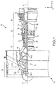
FIG. 1 illustrates an example of a gas turbine engine, in accordance with various embodiments; -
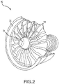
FIG. 2 illustrates a fan having a plurality of fan blades, in accordance with various embodiments; -
FIG. 3A illustrates a cross sectional view of a fan blade having a three-dimensional woven core and skin formed by automated fiber placement of dry fiber tows, in accordance with various embodiments; -
FIG. 3B illustrates a cross sectional view of a fan blade formed by automated fiber placement of dry fiber tows, in accordance with various embodiments; -
FIG. 4 illustrates a diagrammatic view of a blade having a three-dimensional woven core and skin formed by automated fiber placement of dry fiber tows, according to various embodiments; -
FIG. 5 illustrate automated fiber placement of dry fiber tows using a robotic tool, in accordance with various embodiments; and -
FIG. 6 illustrates a method of forming a blade using automated fiber placement of dry fiber tows, in accordance with various embodiments. - The detailed description of exemplary embodiments herein makes reference to the accompanying drawings, which show exemplary embodiments by way of illustration and their best mode. While these exemplary embodiments are described in sufficient detail to enable those skilled in the art to practice the disclosures, it should be understood that other embodiments may be realized and that logical, chemical, and mechanical changes may be made without departing from the scope of the invention as defined by the claims. Thus, the detailed description herein is presented for purposes of illustration only and not of limitation. For example, the steps recited in any of the method or process descriptions may be executed in any order and are not necessarily limited to the order presented. Furthermore, any reference to singular includes plural embodiments, and any reference to more than one component or step may include a singular embodiment or step. Also, any reference to attached, fixed, connected or the like may include permanent, removable, temporary, partial, full and/or any other possible attachment option. Additionally, any reference to without contact (or similar phrases) may also include reduced contact or minimal contact.
- The present disclosure relates to composite fan blades made using Automated Fiber Placement (AFP) of dry fiber tows. AFP may use a robot to place the fiber in tows with a thermoplastic material. Heat may be applied to hold the tows in place by increasing tackiness of the thermoplastic. The preform may be made by adding numerous layers of the dry fiber tows. Reinforcement through the thickness can also be added via tufting or needling. Tufting and/or needling may insert additional fiber through the layers after layup. Various embodiments may also include a three-dimensional woven core in the middle of the preform with only the outer layers formed by AFP of dry fiber tows. The preform can be highly customized for optimal structure. The tows may be held in place in an un-crimped configuration. The robotic placement process allows consistency and repeatability in the manufacturing process. As used herein, dry means substantially free of viscous or adhesive material other than the thermoplastic coating.
- Referring now to
FIG. 1 , an exemplarygas turbine engine 20 is shown, in accordance with various embodiments.Gas turbine engine 20 may be a two-spool turbofan that generally incorporates afan section 22, acompressor section 24, acombustor section 26 and aturbine section 28. Alternative engines may include, for example, an augmentor section among other systems or features. In operation,fan section 22 can drive fluid (e.g., air) along a bypass-flow path B whilecompressor section 24 can drive coolant along a core-flow path C for compression and communication intocombustor section 26 then expansion throughturbine section 28. Although depicted as a two-spool turbofangas turbine engine 20 herein, it should be understood that the concepts described herein are not limited to use with two-spool turbofans as the teachings may be applied to other types of turbine engines including turbojet, turboprop, turboshaft, or power generation turbines, with or without geared fan, geared compressor or three-spool architectures. -
Gas turbine engine 20 may generally comprise alow speed spool 30 and ahigh speed spool 32 mounted for rotation about an engine central longitudinal axis A-A' relative to an enginestatic structure 36 viaseveral bearing systems 38, 38-1, and 38-2. It should be understood that various bearingsystems 38 at various locations may alternatively or additionally be provided, including for example, bearingsystem 38, bearing system 38-1, and bearing system 38-2. -
Low speed spool 30 may generally comprise aninner shaft 40 that interconnects afan 42, a low-pressure compressor 44 and a low-pressure turbine 46.Inner shaft 40 may be connected to fan 42 through a gearedarchitecture 48 that can drivefan 42 at a lower speed thanlow speed spool 30. Fan 42 (or other rotating sections having airfoils such ascompressor section 24 or turbine section 28) may include blades formed from composite materials.Geared architecture 48 may comprise a gear assembly enclosed within a gear housing that couplesinner shaft 40 to a rotating fan structure.High speed spool 32 may comprise anouter shaft 50 that interconnects a high-pressure compressor 52 and high-pressure turbine 54. Airfoils 55 coupled to a rotor of high-pressure turbine may rotate about the engine central longitudinal axis A-A' or airfoils 55 coupled to a stator may be rotationally fixed about engine central longitudinal axis A-A'. - A
combustor 56 may be located between high-pressure compressor 52 and high-pressure turbine 54.Inner shaft 40 andouter shaft 50 may be concentric and rotate via bearingsystems 38 about the engine central longitudinal axis A-A', which is collinear with their longitudinal axes. As used herein, a "high-pressure" compressor or turbine experiences a higher pressure than a corresponding "low-pressure" compressor or turbine. - The core airflow along core-flow path C may be compressed by low-
pressure compressor 44 then high-pressure compressor 52, mixed and burned with fuel incombustor 56, then expanded over high-pressure turbine 54 and low-pressure turbine 46.Turbines low speed spool 30 andhigh speed spool 32 in response to the expansion. - Referring now to
FIG. 2 , afan 42 is shown according to various embodiments.Fan 42 may include ashroud 70 having an annular geometry.Blades 72 may rotate abouthub 74 withinshroud 70. Impact events may occur when debris entersshroud 70 andcontacts blades 72.Blades 72 made from AFP of dry fiber tows may be resistant to delamination in response to impact events while maintaining light weight.Blades 72 may be made either with or without a woven core. The core may be made of fibrous material such as AFP of dry fiber tows and/or woven fibers. - Referring to
FIG. 3A , an exemplary cross section of ablade 72 made using acore 80 and askin 82 made using AFP of dry fiber tows is shown according to various embodiments.Core 80 may be a three-dimensionally woven core made using a loom to weave fibers into a predetermined shape. A three-dimensionally woven core may be a woven structure containing a set of fibrous yarn or tows lying in 3 orthogonal directions (e.g., an x-axis, y-axis, and z-axis). The woven structure may affect the physical properties in three planar directions as compared to two-dimensional woven composite form with yarns lying in only two orthogonal directions (e.g., an x-axis and a y-axis). - In various embodiments,
core 80 may be trimmed to leave fibers in a predetermined shape.Skin 82 may be formed aboutcore 80.Skin 82 may be made using AFP (as show inFIGs. 5 and6 ) to place dry fiber tows directly oncore 80, or fiber placed on a separate tool first, then attaching the dry fiber placed skin to the core. The dry fiber tows may include a plastic or thermoplastic coating to hold the fibers in place during the AFP process. Apreform comprising core 80 andskin 82 may be molded using resin transfer molding (RTM). Generally, RTM includes a process where a molding material having a first material composition (e.g., a resin, a thermosetting material, a thermoplastic material, or the like) is heated and injected into a mold encasing at least a portion of theskin 82 andcore 80. The molding material infiltrates and/or encases theskin 82 andcore 80 and is subsequently cured.Core 80 andskin 82 may be injected with a resin material, such as the resin material commercially available under the tradename Hexcel RTM-6 for example, that lacks thermoplastic additives in response to theskin 82 and/orcore 80 comprising dry fiber tows having a thermoplastic coating. - Referring to
FIG. 3B , an exemplary cross section of ablade 72 made using AFP of dry fiber tows 90 without a three-dimensionally woven core is shown according to various embodiments. Layers of dry fiber tows 90 are built up using an AFP process.Outer surface 92 may also be defined by dry fiber tows placed using AFP. Thedry fiber tow 90 may be treated injected with a molding material using RTM, as described above with reference toFIG. 3A . - Referring to
FIG. 4 , a diagram illustrating the placement of internal fiber tows 102 aboutcore 106 is shown according to various embodiments. Internal fiber tows 102, which are similar toskin 82 ofFIG. 3A andouter surface 92 ofFIG. 3B , are placed in a predetermined orientation oncore 106. Multiple layers of internal fiber tows 102 may be built by placement oncore 106.Core 1 06 may include a three-dimensionally woven core.Core 106 may also comprise many layers of internal fiber tows 102 built by placement one on top of another. External fiber tows 100 may be placed as the outermost layer on either side ofcore 106. The skin (e.g.,skin 82 ofFIG. 3A ) may include one or more layers of dry fiber tows placed using AFP. For example, the skin may include four layers of dry fiber tows placed on either side ofcore 106. - Referring briefly to
FIG. 5 ,robot 110 may be programmed to deposit the tows at various predetermined angles and orientations.Robot 110 may includehead 112 that placesdry fiber tow 113 in position onlower layer 116 of fiber material.Upper layer 117 of fiber material may comprise a multiple dry fiber tows placed byhead 112 onlower layer 116 as robot translateshead 112.Heating device 114 may heat thedry fiber tow 113 to make a thermoplastic coating ondry fiber tow 113 more tacky and retain the layers of fiber material relative to one another. - Referring to
FIG. 4 , internal fiber tows 102 may be placed by a robot operating similar torobot 110 ofFIG. 5 . The robot may place the internal fiber tows 102 and/or external fiber tows 100 with the fiber tows oriented in various directions to augment the strength of a finished blade. For example, fiber tows may point in a first direction at a blade root area and curve to a second direction at a blade tip area. The direction of the fiber tows may be predetermined using computer modeling to identify orientations that strengthen the blade. The fiber tows may also be placed using AFP in un-crimped manner. Fiber tows 100 may also be placed using AFP on a separate tool and then attached tocore 106. - In various embodiments, the various layers of internal fiber tows 102, external fiber tows 100, and/or
core 106 may be laid on a support and needled or tufted together simultaneously or in a series of needling steps. Tufting and/or needling processes may interconnect the horizontal fibers in a third direction (also called the z-direction). The fibers extending into the third direction may be referred to as z-fibers. The needling process may involve driving a multitude of barbed needles into the fibrous layers to displace a portion of the horizontal fibers into the z-direction. Similarly, tufting may involvesewing tufting 104 into the various layers to retain the internal fiber tows 102, external fiber tows 100, and/orcore 106 relative to one another.Tufting 104 may extend partially intocore 106 and/or completely throughcore 106. Tufting may be done on both sides of thecore 106.Resin material 107 may infiltrate the fiber tows and/or core in response to an RTM process. - Referring now to
FIG. 6 , amethod 120 for making a fan blade (e.g.,blade 72 ofFIG. 2 ) is shown, in accordance with various embodiments. A core is formed comprising fibrous material (Step 122). A first layer of dry fiber tows is placed over the core using a robot (Step 124). The first layer of the dry fiber tows may be substantially un-crimped. The first layer of the dry fiber tows may also include a thermoplastic coating. A second layer of the dry fiber tows may be placed over the first layer of the dry fiber tows using the robot (Step 126). The second layer may be similar to the first layer in characteristics. The core, the first layer of the dry fiber tow, and the second layer of the dry fiber tows may be molded using resin transfer molding (Step 128). - Benefits, other advantages, and solutions to problems have been described herein with regard to specific embodiments. Furthermore, the connecting lines shown in the various figures contained herein are intended to represent exemplary functional relationships and/or physical couplings between the various elements. It should be noted that many alternative or additional functional relationships or physical connections may be present in a practical system. However, the benefits, advantages, solutions to problems, and any elements that may cause any benefit, advantage, or solution to occur or become more pronounced are not to be construed as critical, required, or essential features or elements of the disclosures.
- The scope of the disclosures is accordingly to be limited by nothing other than the appended claims, in which reference to an element in the singular is not intended to mean "one and only one" unless explicitly so stated, but rather "one or more." Moreover, where a phrase similar to "at least one of A, B, or C" is used in the claims, it is intended that the phrase be interpreted to mean that A alone may be present in an embodiment, B alone may be present in an embodiment, C alone may be present in an embodiment, or that any combination of the elements A, B and C may be present in a single embodiment; for example, A and B, A and C, B and C, or A and B and C. Different cross-hatching is used throughout the figures to denote different parts but not necessarily to denote the same or different materials.
- Systems, methods and apparatus are provided herein. In the detailed description herein, references to "one embodiment", "an embodiment", "an example embodiment", etc., indicate that the embodiment described may include a particular feature, structure, or characteristic, but every embodiment may not necessarily include the particular feature, structure, or characteristic. Moreover, such phrases are not necessarily referring to the same embodiment. Further, when a particular feature, structure, or characteristic is described in connection with an embodiment, it is submitted that it is within the knowledge of one skilled in the art to affect such feature, structure, or characteristic in connection with other embodiments whether or not explicitly described. After reading the description, it will be apparent to one skilled in the relevant art(s) how to implement the disclosure in alternative embodiment
Claims (15)
- A method of making a fan blade, comprising:forming a core (80) comprising fibrous material;placing a first layer of dry fiber tows (90) over the core using a robot (110), wherein the first layer of dry fiber tows is substantially un-crimped, wherein the first layer of dry fiber tows includes a thermoplastic coating;placing a second layer of dry fiber tows over the first layer of dry fiber tows, wherein the second layer of dry fiber tows is substantially un-crimped, wherein the second layer of dry fiber tows includes the thermoplastic coating; andmolding the core, the first layer of dry fiber tows, and the second layer of dry fiber tows using resin transfer molding.
- The method of claim 1, further comprising trimming the core before the placing the first layer of dry fiber tows over the core.
- The method of claim 1 or 2, wherein the first layer of dry fiber tows is placed over the core in a curved configuration.
- The method of claim 1, 2 or 3, wherein the core comprises a three-dimensionally woven core formed on a loom.
- The method of claim 1, wherein the core comprises a plurality of layers of dry fiber tows placed by the robot.
- The method of any preceding claim, further comprising heating the thermoplastic coating after the placing the first layer of dry fiber tows over the core.
- The method of any preceding claim, further comprising tufting the first layer of dry fiber tows and the second layer of dry fiber tows, or further comprising needling the first layer of dry fiber tows and the second layer of dry fiber tows.
- A fan blade, comprising:a core (80) comprising a fibrous material;a plurality of layers of dry fiber tows (90) placed about the core to form a skin (82), wherein the plurality of layers of dry fiber tows includes a thermoplastic coating, wherein dry fiber tows are substantially un-crimped; anda resin material injected into at least one of the core or the plurality of layers of dry fiber tows.
- The fan blade of claim 8, wherein the fibrous material of the core comprises a plurality of second layers of dry fiber tows.
- The fan blade of claim 8, wherein the plurality of layers of dry fiber tows are curved.
- The fan blade of claim 8, further comprising a tufting disposed in the plurality of layers of dry fiber tows, or
wherein the plurality of layers of dry fiber tows is needled together. - A fan for a gas turbine engine, comprising:a hub;a fan blade (72) coupled to the hub and configured to rotate about the hub, the fan blade comprising:a core (80) comprising fibrous material;a first layer of dry fiber tows (90) placed over the core, wherein the first layer of dry fiber tows is substantially un-crimped, wherein the first layer of dry fiber tows includes a thermoplastic coating; anda shroud (70) disposed about the fan blade.
- The fan of claim 12, wherein the first layer of dry fiber tows is curved relative to a surface of the fan blade.
- The fan of claim 12, wherein the fan blade further comprises a second layer of dry fiber tows placed over the first layer of dry fiber tows.
- The fan of claim 12, wherein the fan blade further comprises a resin material injected into at least one of the core or the first layer of dry fiber tows.
Applications Claiming Priority (1)
| Application Number | Priority Date | Filing Date | Title |
|---|---|---|---|
| US15/374,741 US10626884B2 (en) | 2016-12-09 | 2016-12-09 | Systems and methods for making airfoils |
Publications (2)
| Publication Number | Publication Date |
|---|---|
| EP3332948A1 true EP3332948A1 (en) | 2018-06-13 |
| EP3332948B1 EP3332948B1 (en) | 2025-04-16 |
Family
ID=60661823
Family Applications (1)
| Application Number | Title | Priority Date | Filing Date |
|---|---|---|---|
| EP17206444.6A Active EP3332948B1 (en) | 2016-12-09 | 2017-12-11 | System and method for making fan blades |
Country Status (2)
| Country | Link |
|---|---|
| US (1) | US10626884B2 (en) |
| EP (1) | EP3332948B1 (en) |
Cited By (2)
| Publication number | Priority date | Publication date | Assignee | Title |
|---|---|---|---|---|
| US10858944B2 (en) | 2018-03-09 | 2020-12-08 | Rolls-Royce Plc | Method of manufacturing a fan blade and a fan blade |
| US11440273B2 (en) | 2018-04-11 | 2022-09-13 | Rolls-Royce Plc | Method for forming a composite article |
Families Citing this family (1)
| Publication number | Priority date | Publication date | Assignee | Title |
|---|---|---|---|---|
| FR3085297B1 (en) * | 2018-08-29 | 2020-11-06 | Safran | METHOD OF MANUFACTURING A COMPOSITE PART OF A TURBOMACHINE |
Citations (2)
| Publication number | Priority date | Publication date | Assignee | Title |
|---|---|---|---|---|
| US20130174969A1 (en) * | 2010-04-16 | 2013-07-11 | Compositence Gmbh | Apparatus and Method for Manufacturing Fibre Layers |
| US20160032939A1 (en) * | 2014-07-31 | 2016-02-04 | General Electric Company | Airfoil structures |
Family Cites Families (18)
| Publication number | Priority date | Publication date | Assignee | Title |
|---|---|---|---|---|
| US4622091A (en) | 1984-11-29 | 1986-11-11 | The Boeing Company | Resin film infusion process and apparatus |
| US4988469A (en) | 1988-11-21 | 1991-01-29 | United Technologies Corporation | Method of fabricating fiber reinforced composite articles by resin transfer molding |
| US5222297A (en) | 1991-10-18 | 1993-06-29 | United Technologies Corporation | Composite blade manufacture |
| US5279892A (en) | 1992-06-26 | 1994-01-18 | General Electric Company | Composite airfoil with woven insert |
| US6431837B1 (en) | 1999-06-01 | 2002-08-13 | Alexander Velicki | Stitched composite fan blade |
| CN100509385C (en) | 2002-11-01 | 2009-07-08 | 贝尔直升机泰克斯特龙公司 | Method and apparatus for Z-direction reinforcement of composite laminates |
| GB0424481D0 (en) * | 2004-11-05 | 2004-12-08 | Rolls Royce Plc | Composite aerofoil |
| GB0428201D0 (en) | 2004-12-22 | 2005-01-26 | Rolls Royce Plc | A composite blade |
| US7943535B2 (en) * | 2005-11-17 | 2011-05-17 | Albany Engineered Composites, Inc. | Hybrid three-dimensional woven/laminated struts for composite structural applications |
| JP5584224B2 (en) * | 2008-10-23 | 2014-09-03 | ヘクセル ランフォルセマン | New reinforcing material suitable for the production of composite parts |
| FR2939069B1 (en) * | 2008-11-28 | 2013-03-01 | Hexcel Reinforcements | NEW INTERMEDIATE MATERIAL OF CONSTANT WIDTH FOR THE PRODUCTION OF COMPOSITE PARTS BY DIRECT PROCESS. |
| FR2945549B1 (en) * | 2009-05-12 | 2012-07-27 | Arkema France | FIBROUS SUBSTRATE, METHOD FOR MANUFACTURING AND USE OF SUCH A FIBROUS SUBSTRATE |
| FR2954271B1 (en) | 2009-12-21 | 2012-02-17 | Snecma | AIRCRAFT PROPELLER BLADE |
| WO2014079565A2 (en) * | 2012-11-20 | 2014-05-30 | Hexcel Composites Limited | Moulding material |
| US20140169972A1 (en) * | 2012-12-17 | 2014-06-19 | United Technologies Corporation | Fan with integral shroud |
| EP2987819B1 (en) * | 2013-04-19 | 2019-02-27 | Toray Industries, Inc. | Method for producing reinforcing fiber sheet |
| US9259858B2 (en) | 2013-10-18 | 2016-02-16 | Green Dynamics Corporation | Laminate stitching method for improved fiber logistics and placement precision |
| US10414142B2 (en) | 2014-12-29 | 2019-09-17 | Rolls-Royce Corporation | Needle punching of composites for preform assembly and thermomechanical enhancement |
-
2016
- 2016-12-09 US US15/374,741 patent/US10626884B2/en active Active
-
2017
- 2017-12-11 EP EP17206444.6A patent/EP3332948B1/en active Active
Patent Citations (2)
| Publication number | Priority date | Publication date | Assignee | Title |
|---|---|---|---|---|
| US20130174969A1 (en) * | 2010-04-16 | 2013-07-11 | Compositence Gmbh | Apparatus and Method for Manufacturing Fibre Layers |
| US20160032939A1 (en) * | 2014-07-31 | 2016-02-04 | General Electric Company | Airfoil structures |
Cited By (4)
| Publication number | Priority date | Publication date | Assignee | Title |
|---|---|---|---|---|
| US10858944B2 (en) | 2018-03-09 | 2020-12-08 | Rolls-Royce Plc | Method of manufacturing a fan blade and a fan blade |
| US11187084B2 (en) | 2018-03-09 | 2021-11-30 | Rolls-Royce Plc | Method of manufacturing a fan blade and a fan blade |
| US11441429B2 (en) | 2018-03-09 | 2022-09-13 | Rolls-Royce Plc | Composite fan blade and manufacturing method thereof |
| US11440273B2 (en) | 2018-04-11 | 2022-09-13 | Rolls-Royce Plc | Method for forming a composite article |
Also Published As
| Publication number | Publication date |
|---|---|
| EP3332948B1 (en) | 2025-04-16 |
| US10626884B2 (en) | 2020-04-21 |
| US20180163745A1 (en) | 2018-06-14 |
Similar Documents
| Publication | Publication Date | Title |
|---|---|---|
| EP3564487B1 (en) | Composite airfoil for gas turbine engines and corresponding method of forming | |
| EP3292991B1 (en) | Fiber composite material for a fan blade | |
| JP5974111B2 (en) | Composite storage case for gas turbine fan and manufacturing method thereof | |
| US9988156B2 (en) | Cylindrical case and manufacturing method of cylindrical case | |
| EP3287265B1 (en) | Gas-turbine engine composite components with integral 3-d woven off-axis reinforcement | |
| US9309772B2 (en) | Hybrid turbine blade including multiple insert sections | |
| EP3332948B1 (en) | System and method for making fan blades | |
| EP2971549B1 (en) | Gas turbine engine blade, corresponding gas turbine engine and method of forming | |
| WO2013123195A1 (en) | Case with ballistic liner | |
| EP3587736B1 (en) | Composite airfoil with fibres forming a cleft in the platform | |
| CN110080825B (en) | Composite article including composite to metal interlock and method of making | |
| EP2959131B1 (en) | Composite attachment structure with 3d weave | |
| EP3543467B1 (en) | Composite airfoil comprising a ply having plurality of fiber angles and associated method of manufacturing | |
| CN114127387A (en) | blower vanes | |
| US20260071549A1 (en) | Hybrid composite architecture for composite fan blade impact robustness | |
| CN121989478A (en) | Methods for manufacturing composite components for gas turbine engines | |
| CN120921742A (en) | Method of manufacturing a composite component of a gas turbine engine | |
| CN121989469A (en) | Preforms for composite airfoils used in turbine engines | |
| CN121006641A (en) | Method for manufacturing woven fabrics for composite components of turbine engines | |
| CN121047650A (en) | Method for manufacturing woven fabrics for composite components |
Legal Events
| Date | Code | Title | Description |
|---|---|---|---|
| PUAI | Public reference made under article 153(3) epc to a published international application that has entered the european phase |
Free format text: ORIGINAL CODE: 0009012 |
|
| STAA | Information on the status of an ep patent application or granted ep patent |
Free format text: STATUS: THE APPLICATION HAS BEEN PUBLISHED |
|
| AK | Designated contracting states |
Kind code of ref document: A1 Designated state(s): AL AT BE BG CH CY CZ DE DK EE ES FI FR GB GR HR HU IE IS IT LI LT LU LV MC MK MT NL NO PL PT RO RS SE SI SK SM TR |
|
| AX | Request for extension of the european patent |
Extension state: BA ME |
|
| STAA | Information on the status of an ep patent application or granted ep patent |
Free format text: STATUS: REQUEST FOR EXAMINATION WAS MADE |
|
| 17P | Request for examination filed |
Effective date: 20181213 |
|
| RBV | Designated contracting states (corrected) |
Designated state(s): AL AT BE BG CH CY CZ DE DK EE ES FI FR GB GR HR HU IE IS IT LI LT LU LV MC MK MT NL NO PL PT RO RS SE SI SK SM TR |
|
| STAA | Information on the status of an ep patent application or granted ep patent |
Free format text: STATUS: EXAMINATION IS IN PROGRESS |
|
| 17Q | First examination report despatched |
Effective date: 20201208 |
|
| GRAP | Despatch of communication of intention to grant a patent |
Free format text: ORIGINAL CODE: EPIDOSNIGR1 |
|
| STAA | Information on the status of an ep patent application or granted ep patent |
Free format text: STATUS: GRANT OF PATENT IS INTENDED |
|
| INTG | Intention to grant announced |
Effective date: 20241125 |
|
| GRAS | Grant fee paid |
Free format text: ORIGINAL CODE: EPIDOSNIGR3 |
|
| GRAA | (expected) grant |
Free format text: ORIGINAL CODE: 0009210 |
|
| STAA | Information on the status of an ep patent application or granted ep patent |
Free format text: STATUS: THE PATENT HAS BEEN GRANTED |
|
| AK | Designated contracting states |
Kind code of ref document: B1 Designated state(s): AL AT BE BG CH CY CZ DE DK EE ES FI FR GB GR HR HU IE IS IT LI LT LU LV MC MK MT NL NO PL PT RO RS SE SI SK SM TR |
|
| REG | Reference to a national code |
Ref country code: GB Ref legal event code: FG4D |
|
| REG | Reference to a national code |
Ref country code: CH Ref legal event code: EP Ref country code: DE Ref legal event code: R096 Ref document number: 602017088922 Country of ref document: DE |
|
| REG | Reference to a national code |
Ref country code: IE Ref legal event code: FG4D |
|
| REG | Reference to a national code |
Ref country code: NL Ref legal event code: MP Effective date: 20250416 |
|
| PG25 | Lapsed in a contracting state [announced via postgrant information from national office to epo] |
Ref country code: NL Free format text: LAPSE BECAUSE OF FAILURE TO SUBMIT A TRANSLATION OF THE DESCRIPTION OR TO PAY THE FEE WITHIN THE PRESCRIBED TIME-LIMIT Effective date: 20250416 |
|
| REG | Reference to a national code |
Ref country code: AT Ref legal event code: MK05 Ref document number: 1785307 Country of ref document: AT Kind code of ref document: T Effective date: 20250416 |
|
| PG25 | Lapsed in a contracting state [announced via postgrant information from national office to epo] |
Ref country code: PT Free format text: LAPSE BECAUSE OF FAILURE TO SUBMIT A TRANSLATION OF THE DESCRIPTION OR TO PAY THE FEE WITHIN THE PRESCRIBED TIME-LIMIT Effective date: 20250818 Ref country code: FI Free format text: LAPSE BECAUSE OF FAILURE TO SUBMIT A TRANSLATION OF THE DESCRIPTION OR TO PAY THE FEE WITHIN THE PRESCRIBED TIME-LIMIT Effective date: 20250416 Ref country code: ES Free format text: LAPSE BECAUSE OF FAILURE TO SUBMIT A TRANSLATION OF THE DESCRIPTION OR TO PAY THE FEE WITHIN THE PRESCRIBED TIME-LIMIT Effective date: 20250416 |
|
| REG | Reference to a national code |
Ref country code: LT Ref legal event code: MG9D |
|
| PG25 | Lapsed in a contracting state [announced via postgrant information from national office to epo] |
Ref country code: NO Free format text: LAPSE BECAUSE OF FAILURE TO SUBMIT A TRANSLATION OF THE DESCRIPTION OR TO PAY THE FEE WITHIN THE PRESCRIBED TIME-LIMIT Effective date: 20250716 Ref country code: GR Free format text: LAPSE BECAUSE OF FAILURE TO SUBMIT A TRANSLATION OF THE DESCRIPTION OR TO PAY THE FEE WITHIN THE PRESCRIBED TIME-LIMIT Effective date: 20250717 |
|
| PG25 | Lapsed in a contracting state [announced via postgrant information from national office to epo] |
Ref country code: PL Free format text: LAPSE BECAUSE OF FAILURE TO SUBMIT A TRANSLATION OF THE DESCRIPTION OR TO PAY THE FEE WITHIN THE PRESCRIBED TIME-LIMIT Effective date: 20250416 |
|
| PG25 | Lapsed in a contracting state [announced via postgrant information from national office to epo] |
Ref country code: BG Free format text: LAPSE BECAUSE OF FAILURE TO SUBMIT A TRANSLATION OF THE DESCRIPTION OR TO PAY THE FEE WITHIN THE PRESCRIBED TIME-LIMIT Effective date: 20250416 |
|
| PG25 | Lapsed in a contracting state [announced via postgrant information from national office to epo] |
Ref country code: HR Free format text: LAPSE BECAUSE OF FAILURE TO SUBMIT A TRANSLATION OF THE DESCRIPTION OR TO PAY THE FEE WITHIN THE PRESCRIBED TIME-LIMIT Effective date: 20250416 |
|
| PG25 | Lapsed in a contracting state [announced via postgrant information from national office to epo] |
Ref country code: AT Free format text: LAPSE BECAUSE OF FAILURE TO SUBMIT A TRANSLATION OF THE DESCRIPTION OR TO PAY THE FEE WITHIN THE PRESCRIBED TIME-LIMIT Effective date: 20250416 |
|
| PG25 | Lapsed in a contracting state [announced via postgrant information from national office to epo] |
Ref country code: RS Free format text: LAPSE BECAUSE OF FAILURE TO SUBMIT A TRANSLATION OF THE DESCRIPTION OR TO PAY THE FEE WITHIN THE PRESCRIBED TIME-LIMIT Effective date: 20250716 |
|
| PG25 | Lapsed in a contracting state [announced via postgrant information from national office to epo] |
Ref country code: IS Free format text: LAPSE BECAUSE OF FAILURE TO SUBMIT A TRANSLATION OF THE DESCRIPTION OR TO PAY THE FEE WITHIN THE PRESCRIBED TIME-LIMIT Effective date: 20250816 |
|
| PG25 | Lapsed in a contracting state [announced via postgrant information from national office to epo] |
Ref country code: LV Free format text: LAPSE BECAUSE OF FAILURE TO SUBMIT A TRANSLATION OF THE DESCRIPTION OR TO PAY THE FEE WITHIN THE PRESCRIBED TIME-LIMIT Effective date: 20250416 |
|
| PGFP | Annual fee paid to national office [announced via postgrant information from national office to epo] |
Ref country code: GB Payment date: 20251119 Year of fee payment: 9 |
|
| PG25 | Lapsed in a contracting state [announced via postgrant information from national office to epo] |
Ref country code: SM Free format text: LAPSE BECAUSE OF FAILURE TO SUBMIT A TRANSLATION OF THE DESCRIPTION OR TO PAY THE FEE WITHIN THE PRESCRIBED TIME-LIMIT Effective date: 20250416 Ref country code: DK Free format text: LAPSE BECAUSE OF FAILURE TO SUBMIT A TRANSLATION OF THE DESCRIPTION OR TO PAY THE FEE WITHIN THE PRESCRIBED TIME-LIMIT Effective date: 20250416 |
|
| PGFP | Annual fee paid to national office [announced via postgrant information from national office to epo] |
Ref country code: FR Payment date: 20251120 Year of fee payment: 9 |
|
| REG | Reference to a national code |
Ref country code: DE Ref legal event code: R097 Ref document number: 602017088922 Country of ref document: DE |
|
| PG25 | Lapsed in a contracting state [announced via postgrant information from national office to epo] |
Ref country code: CZ Free format text: LAPSE BECAUSE OF FAILURE TO SUBMIT A TRANSLATION OF THE DESCRIPTION OR TO PAY THE FEE WITHIN THE PRESCRIBED TIME-LIMIT Effective date: 20250416 |
|
| PG25 | Lapsed in a contracting state [announced via postgrant information from national office to epo] |
Ref country code: EE Free format text: LAPSE BECAUSE OF FAILURE TO SUBMIT A TRANSLATION OF THE DESCRIPTION OR TO PAY THE FEE WITHIN THE PRESCRIBED TIME-LIMIT Effective date: 20250416 |
|
| PG25 | Lapsed in a contracting state [announced via postgrant information from national office to epo] |
Ref country code: SK Free format text: LAPSE BECAUSE OF FAILURE TO SUBMIT A TRANSLATION OF THE DESCRIPTION OR TO PAY THE FEE WITHIN THE PRESCRIBED TIME-LIMIT Effective date: 20250416 Ref country code: RO Free format text: LAPSE BECAUSE OF FAILURE TO SUBMIT A TRANSLATION OF THE DESCRIPTION OR TO PAY THE FEE WITHIN THE PRESCRIBED TIME-LIMIT Effective date: 20250416 |
|
| PG25 | Lapsed in a contracting state [announced via postgrant information from national office to epo] |
Ref country code: IT Free format text: LAPSE BECAUSE OF FAILURE TO SUBMIT A TRANSLATION OF THE DESCRIPTION OR TO PAY THE FEE WITHIN THE PRESCRIBED TIME-LIMIT Effective date: 20250416 |
|
| PLBE | No opposition filed within time limit |
Free format text: ORIGINAL CODE: 0009261 |
|
| STAA | Information on the status of an ep patent application or granted ep patent |
Free format text: STATUS: NO OPPOSITION FILED WITHIN TIME LIMIT |
|
| REG | Reference to a national code |
Ref country code: CH Ref legal event code: L10 Free format text: ST27 STATUS EVENT CODE: U-0-0-L10-L00 (AS PROVIDED BY THE NATIONAL OFFICE) Effective date: 20260225 |
|
| 26N | No opposition filed |
Effective date: 20260119 |