EP3332945A1 - Hot joint fastener - Google Patents
Hot joint fastener Download PDFInfo
- Publication number
- EP3332945A1 EP3332945A1 EP16203398.9A EP16203398A EP3332945A1 EP 3332945 A1 EP3332945 A1 EP 3332945A1 EP 16203398 A EP16203398 A EP 16203398A EP 3332945 A1 EP3332945 A1 EP 3332945A1
- Authority
- EP
- European Patent Office
- Prior art keywords
- component
- components
- fastener
- joined
- fiber composite
- Prior art date
- Legal status (The legal status is an assumption and is not a legal conclusion. Google has not performed a legal analysis and makes no representation as to the accuracy of the status listed.)
- Granted
Links
Images









Classifications
-
- B—PERFORMING OPERATIONS; TRANSPORTING
- B29—WORKING OF PLASTICS; WORKING OF SUBSTANCES IN A PLASTIC STATE IN GENERAL
- B29C—SHAPING OR JOINING OF PLASTICS; SHAPING OF MATERIAL IN A PLASTIC STATE, NOT OTHERWISE PROVIDED FOR; AFTER-TREATMENT OF THE SHAPED PRODUCTS, e.g. REPAIRING
- B29C65/00—Joining or sealing of preformed parts, e.g. welding of plastics materials; Apparatus therefor
- B29C65/56—Joining or sealing of preformed parts, e.g. welding of plastics materials; Apparatus therefor using mechanical means or mechanical connections, e.g. form-fits
- B29C65/562—Joining or sealing of preformed parts, e.g. welding of plastics materials; Apparatus therefor using mechanical means or mechanical connections, e.g. form-fits using extra joining elements, i.e. which are not integral with the parts to be joined
-
- F—MECHANICAL ENGINEERING; LIGHTING; HEATING; WEAPONS; BLASTING
- F16—ENGINEERING ELEMENTS AND UNITS; GENERAL MEASURES FOR PRODUCING AND MAINTAINING EFFECTIVE FUNCTIONING OF MACHINES OR INSTALLATIONS; THERMAL INSULATION IN GENERAL
- F16B—DEVICES FOR FASTENING OR SECURING CONSTRUCTIONAL ELEMENTS OR MACHINE PARTS TOGETHER, e.g. NAILS, BOLTS, CIRCLIPS, CLAMPS, CLIPS OR WEDGES; JOINTS OR JOINTING
- F16B37/00—Nuts or like thread-engaging members
- F16B37/04—Devices for fastening nuts to surfaces, e.g. sheets, plates
- F16B37/06—Devices for fastening nuts to surfaces, e.g. sheets, plates by means of welding or riveting
- F16B37/062—Devices for fastening nuts to surfaces, e.g. sheets, plates by means of welding or riveting by means of riveting
- F16B37/065—Devices for fastening nuts to surfaces, e.g. sheets, plates by means of welding or riveting by means of riveting by deforming the material of the nut
- F16B37/067—Devices for fastening nuts to surfaces, e.g. sheets, plates by means of welding or riveting by means of riveting by deforming the material of the nut the material of the nut being deformed by a threaded member generating axial movement of the threaded part of the nut, e.g. blind rivet type
-
- B—PERFORMING OPERATIONS; TRANSPORTING
- B21—MECHANICAL METAL-WORKING WITHOUT ESSENTIALLY REMOVING MATERIAL; PUNCHING METAL
- B21J—FORGING; HAMMERING; PRESSING METAL; RIVETING; FORGE FURNACES
- B21J15/00—Riveting
- B21J15/02—Riveting procedures
- B21J15/08—Riveting by applying heat, e.g. to the end parts of the rivets to enable heads to be formed
-
- B—PERFORMING OPERATIONS; TRANSPORTING
- B29—WORKING OF PLASTICS; WORKING OF SUBSTANCES IN A PLASTIC STATE IN GENERAL
- B29C—SHAPING OR JOINING OF PLASTICS; SHAPING OF MATERIAL IN A PLASTIC STATE, NOT OTHERWISE PROVIDED FOR; AFTER-TREATMENT OF THE SHAPED PRODUCTS, e.g. REPAIRING
- B29C66/00—General aspects of processes or apparatus for joining preformed parts
- B29C66/01—General aspects dealing with the joint area or with the area to be joined
- B29C66/02—Preparation of the material, in the area to be joined, prior to joining or welding
- B29C66/024—Thermal pre-treatments
- B29C66/0242—Heating, or preheating, e.g. drying
-
- B—PERFORMING OPERATIONS; TRANSPORTING
- B29—WORKING OF PLASTICS; WORKING OF SUBSTANCES IN A PLASTIC STATE IN GENERAL
- B29C—SHAPING OR JOINING OF PLASTICS; SHAPING OF MATERIAL IN A PLASTIC STATE, NOT OTHERWISE PROVIDED FOR; AFTER-TREATMENT OF THE SHAPED PRODUCTS, e.g. REPAIRING
- B29C66/00—General aspects of processes or apparatus for joining preformed parts
- B29C66/01—General aspects dealing with the joint area or with the area to be joined
- B29C66/05—Particular design of joint configurations
- B29C66/10—Particular design of joint configurations particular design of the joint cross-sections
- B29C66/11—Joint cross-sections comprising a single joint-segment, i.e. one of the parts to be joined comprising a single joint-segment in the joint cross-section
- B29C66/112—Single lapped joints
- B29C66/1122—Single lap to lap joints, i.e. overlap joints
-
- B—PERFORMING OPERATIONS; TRANSPORTING
- B29—WORKING OF PLASTICS; WORKING OF SUBSTANCES IN A PLASTIC STATE IN GENERAL
- B29C—SHAPING OR JOINING OF PLASTICS; SHAPING OF MATERIAL IN A PLASTIC STATE, NOT OTHERWISE PROVIDED FOR; AFTER-TREATMENT OF THE SHAPED PRODUCTS, e.g. REPAIRING
- B29C66/00—General aspects of processes or apparatus for joining preformed parts
- B29C66/40—General aspects of joining substantially flat articles, e.g. plates, sheets or web-like materials; Making flat seams in tubular or hollow articles; Joining single elements to substantially flat surfaces
- B29C66/41—Joining substantially flat articles ; Making flat seams in tubular or hollow articles
-
- B—PERFORMING OPERATIONS; TRANSPORTING
- B29—WORKING OF PLASTICS; WORKING OF SUBSTANCES IN A PLASTIC STATE IN GENERAL
- B29C—SHAPING OR JOINING OF PLASTICS; SHAPING OF MATERIAL IN A PLASTIC STATE, NOT OTHERWISE PROVIDED FOR; AFTER-TREATMENT OF THE SHAPED PRODUCTS, e.g. REPAIRING
- B29C66/00—General aspects of processes or apparatus for joining preformed parts
- B29C66/70—General aspects of processes or apparatus for joining preformed parts characterised by the composition, physical properties or the structure of the material of the parts to be joined; Joining with non-plastics material
- B29C66/72—General aspects of processes or apparatus for joining preformed parts characterised by the composition, physical properties or the structure of the material of the parts to be joined; Joining with non-plastics material characterised by the structure of the material of the parts to be joined
- B29C66/721—Fibre-reinforced materials
-
- B—PERFORMING OPERATIONS; TRANSPORTING
- B29—WORKING OF PLASTICS; WORKING OF SUBSTANCES IN A PLASTIC STATE IN GENERAL
- B29C—SHAPING OR JOINING OF PLASTICS; SHAPING OF MATERIAL IN A PLASTIC STATE, NOT OTHERWISE PROVIDED FOR; AFTER-TREATMENT OF THE SHAPED PRODUCTS, e.g. REPAIRING
- B29C66/00—General aspects of processes or apparatus for joining preformed parts
- B29C66/70—General aspects of processes or apparatus for joining preformed parts characterised by the composition, physical properties or the structure of the material of the parts to be joined; Joining with non-plastics material
- B29C66/72—General aspects of processes or apparatus for joining preformed parts characterised by the composition, physical properties or the structure of the material of the parts to be joined; Joining with non-plastics material characterised by the structure of the material of the parts to be joined
- B29C66/721—Fibre-reinforced materials
- B29C66/7214—Fibre-reinforced materials characterised by the length of the fibres
- B29C66/72143—Fibres of discontinuous lengths
-
- B—PERFORMING OPERATIONS; TRANSPORTING
- B29—WORKING OF PLASTICS; WORKING OF SUBSTANCES IN A PLASTIC STATE IN GENERAL
- B29C—SHAPING OR JOINING OF PLASTICS; SHAPING OF MATERIAL IN A PLASTIC STATE, NOT OTHERWISE PROVIDED FOR; AFTER-TREATMENT OF THE SHAPED PRODUCTS, e.g. REPAIRING
- B29C66/00—General aspects of processes or apparatus for joining preformed parts
- B29C66/70—General aspects of processes or apparatus for joining preformed parts characterised by the composition, physical properties or the structure of the material of the parts to be joined; Joining with non-plastics material
- B29C66/73—General aspects of processes or apparatus for joining preformed parts characterised by the composition, physical properties or the structure of the material of the parts to be joined; Joining with non-plastics material characterised by the intensive physical properties of the material of the parts to be joined, by the optical properties of the material of the parts to be joined, by the extensive physical properties of the parts to be joined, by the state of the material of the parts to be joined or by the material of the parts to be joined being a thermoplastic or a thermoset
- B29C66/739—General aspects of processes or apparatus for joining preformed parts characterised by the composition, physical properties or the structure of the material of the parts to be joined; Joining with non-plastics material characterised by the intensive physical properties of the material of the parts to be joined, by the optical properties of the material of the parts to be joined, by the extensive physical properties of the parts to be joined, by the state of the material of the parts to be joined or by the material of the parts to be joined being a thermoplastic or a thermoset characterised by the material of the parts to be joined being a thermoplastic or a thermoset
- B29C66/7392—General aspects of processes or apparatus for joining preformed parts characterised by the composition, physical properties or the structure of the material of the parts to be joined; Joining with non-plastics material characterised by the intensive physical properties of the material of the parts to be joined, by the optical properties of the material of the parts to be joined, by the extensive physical properties of the parts to be joined, by the state of the material of the parts to be joined or by the material of the parts to be joined being a thermoplastic or a thermoset characterised by the material of the parts to be joined being a thermoplastic or a thermoset characterised by the material of at least one of the parts being a thermoplastic
-
- B—PERFORMING OPERATIONS; TRANSPORTING
- B29—WORKING OF PLASTICS; WORKING OF SUBSTANCES IN A PLASTIC STATE IN GENERAL
- B29C—SHAPING OR JOINING OF PLASTICS; SHAPING OF MATERIAL IN A PLASTIC STATE, NOT OTHERWISE PROVIDED FOR; AFTER-TREATMENT OF THE SHAPED PRODUCTS, e.g. REPAIRING
- B29C66/00—General aspects of processes or apparatus for joining preformed parts
- B29C66/70—General aspects of processes or apparatus for joining preformed parts characterised by the composition, physical properties or the structure of the material of the parts to be joined; Joining with non-plastics material
- B29C66/73—General aspects of processes or apparatus for joining preformed parts characterised by the composition, physical properties or the structure of the material of the parts to be joined; Joining with non-plastics material characterised by the intensive physical properties of the material of the parts to be joined, by the optical properties of the material of the parts to be joined, by the extensive physical properties of the parts to be joined, by the state of the material of the parts to be joined or by the material of the parts to be joined being a thermoplastic or a thermoset
- B29C66/739—General aspects of processes or apparatus for joining preformed parts characterised by the composition, physical properties or the structure of the material of the parts to be joined; Joining with non-plastics material characterised by the intensive physical properties of the material of the parts to be joined, by the optical properties of the material of the parts to be joined, by the extensive physical properties of the parts to be joined, by the state of the material of the parts to be joined or by the material of the parts to be joined being a thermoplastic or a thermoset characterised by the material of the parts to be joined being a thermoplastic or a thermoset
- B29C66/7394—General aspects of processes or apparatus for joining preformed parts characterised by the composition, physical properties or the structure of the material of the parts to be joined; Joining with non-plastics material characterised by the intensive physical properties of the material of the parts to be joined, by the optical properties of the material of the parts to be joined, by the extensive physical properties of the parts to be joined, by the state of the material of the parts to be joined or by the material of the parts to be joined being a thermoplastic or a thermoset characterised by the material of the parts to be joined being a thermoplastic or a thermoset characterised by the material of at least one of the parts being a thermoset
- B29C66/73941—General aspects of processes or apparatus for joining preformed parts characterised by the composition, physical properties or the structure of the material of the parts to be joined; Joining with non-plastics material characterised by the intensive physical properties of the material of the parts to be joined, by the optical properties of the material of the parts to be joined, by the extensive physical properties of the parts to be joined, by the state of the material of the parts to be joined or by the material of the parts to be joined being a thermoplastic or a thermoset characterised by the material of the parts to be joined being a thermoplastic or a thermoset characterised by the material of at least one of the parts being a thermoset characterised by the materials of both parts being thermosets
-
- B—PERFORMING OPERATIONS; TRANSPORTING
- B64—AIRCRAFT; AVIATION; COSMONAUTICS
- B64C—AEROPLANES; HELICOPTERS
- B64C1/00—Fuselages; Constructional features common to fuselages, wings, stabilising surfaces or the like
- B64C1/06—Frames; Stringers; Longerons ; Fuselage sections
- B64C1/12—Construction or attachment of skin panels
-
- F—MECHANICAL ENGINEERING; LIGHTING; HEATING; WEAPONS; BLASTING
- F16—ENGINEERING ELEMENTS AND UNITS; GENERAL MEASURES FOR PRODUCING AND MAINTAINING EFFECTIVE FUNCTIONING OF MACHINES OR INSTALLATIONS; THERMAL INSULATION IN GENERAL
- F16B—DEVICES FOR FASTENING OR SECURING CONSTRUCTIONAL ELEMENTS OR MACHINE PARTS TOGETHER, e.g. NAILS, BOLTS, CIRCLIPS, CLAMPS, CLIPS OR WEDGES; JOINTS OR JOINTING
- F16B25/00—Screws that cut thread in the body into which they are screwed, e.g. wood screws
- F16B25/001—Screws that cut thread in the body into which they are screwed, e.g. wood screws characterised by the material of the body into which the screw is screwed
- F16B25/0015—Screws that cut thread in the body into which they are screwed, e.g. wood screws characterised by the material of the body into which the screw is screwed the material being a soft organic material, e.g. wood or plastic
-
- F—MECHANICAL ENGINEERING; LIGHTING; HEATING; WEAPONS; BLASTING
- F16—ENGINEERING ELEMENTS AND UNITS; GENERAL MEASURES FOR PRODUCING AND MAINTAINING EFFECTIVE FUNCTIONING OF MACHINES OR INSTALLATIONS; THERMAL INSULATION IN GENERAL
- F16B—DEVICES FOR FASTENING OR SECURING CONSTRUCTIONAL ELEMENTS OR MACHINE PARTS TOGETHER, e.g. NAILS, BOLTS, CIRCLIPS, CLAMPS, CLIPS OR WEDGES; JOINTS OR JOINTING
- F16B39/00—Locking of screws, bolts or nuts
- F16B39/02—Locking of screws, bolts or nuts in which the locking takes place after screwing down
-
- B—PERFORMING OPERATIONS; TRANSPORTING
- B29—WORKING OF PLASTICS; WORKING OF SUBSTANCES IN A PLASTIC STATE IN GENERAL
- B29C—SHAPING OR JOINING OF PLASTICS; SHAPING OF MATERIAL IN A PLASTIC STATE, NOT OTHERWISE PROVIDED FOR; AFTER-TREATMENT OF THE SHAPED PRODUCTS, e.g. REPAIRING
- B29C2793/00—Shaping techniques involving a cutting or machining operation
- B29C2793/0045—Perforating
-
- B—PERFORMING OPERATIONS; TRANSPORTING
- B29—WORKING OF PLASTICS; WORKING OF SUBSTANCES IN A PLASTIC STATE IN GENERAL
- B29C—SHAPING OR JOINING OF PLASTICS; SHAPING OF MATERIAL IN A PLASTIC STATE, NOT OTHERWISE PROVIDED FOR; AFTER-TREATMENT OF THE SHAPED PRODUCTS, e.g. REPAIRING
- B29C65/00—Joining or sealing of preformed parts, e.g. welding of plastics materials; Apparatus therefor
- B29C65/02—Joining or sealing of preformed parts, e.g. welding of plastics materials; Apparatus therefor by heating, with or without pressure
-
- B—PERFORMING OPERATIONS; TRANSPORTING
- B29—WORKING OF PLASTICS; WORKING OF SUBSTANCES IN A PLASTIC STATE IN GENERAL
- B29C—SHAPING OR JOINING OF PLASTICS; SHAPING OF MATERIAL IN A PLASTIC STATE, NOT OTHERWISE PROVIDED FOR; AFTER-TREATMENT OF THE SHAPED PRODUCTS, e.g. REPAIRING
- B29C65/00—Joining or sealing of preformed parts, e.g. welding of plastics materials; Apparatus therefor
- B29C65/02—Joining or sealing of preformed parts, e.g. welding of plastics materials; Apparatus therefor by heating, with or without pressure
- B29C65/08—Joining or sealing of preformed parts, e.g. welding of plastics materials; Apparatus therefor by heating, with or without pressure using ultrasonic vibrations
-
- B—PERFORMING OPERATIONS; TRANSPORTING
- B29—WORKING OF PLASTICS; WORKING OF SUBSTANCES IN A PLASTIC STATE IN GENERAL
- B29C—SHAPING OR JOINING OF PLASTICS; SHAPING OF MATERIAL IN A PLASTIC STATE, NOT OTHERWISE PROVIDED FOR; AFTER-TREATMENT OF THE SHAPED PRODUCTS, e.g. REPAIRING
- B29C65/00—Joining or sealing of preformed parts, e.g. welding of plastics materials; Apparatus therefor
- B29C65/02—Joining or sealing of preformed parts, e.g. welding of plastics materials; Apparatus therefor by heating, with or without pressure
- B29C65/10—Joining or sealing of preformed parts, e.g. welding of plastics materials; Apparatus therefor by heating, with or without pressure using hot gases (e.g. combustion gases) or flames coming in contact with at least one of the parts to be joined
-
- B—PERFORMING OPERATIONS; TRANSPORTING
- B29—WORKING OF PLASTICS; WORKING OF SUBSTANCES IN A PLASTIC STATE IN GENERAL
- B29C—SHAPING OR JOINING OF PLASTICS; SHAPING OF MATERIAL IN A PLASTIC STATE, NOT OTHERWISE PROVIDED FOR; AFTER-TREATMENT OF THE SHAPED PRODUCTS, e.g. REPAIRING
- B29C65/00—Joining or sealing of preformed parts, e.g. welding of plastics materials; Apparatus therefor
- B29C65/02—Joining or sealing of preformed parts, e.g. welding of plastics materials; Apparatus therefor by heating, with or without pressure
- B29C65/14—Joining or sealing of preformed parts, e.g. welding of plastics materials; Apparatus therefor by heating, with or without pressure using wave energy, i.e. electromagnetic radiation, or particle radiation
- B29C65/1403—Joining or sealing of preformed parts, e.g. welding of plastics materials; Apparatus therefor by heating, with or without pressure using wave energy, i.e. electromagnetic radiation, or particle radiation characterised by the type of electromagnetic or particle radiation
- B29C65/1412—Infrared [IR] radiation
-
- B—PERFORMING OPERATIONS; TRANSPORTING
- B29—WORKING OF PLASTICS; WORKING OF SUBSTANCES IN A PLASTIC STATE IN GENERAL
- B29C—SHAPING OR JOINING OF PLASTICS; SHAPING OF MATERIAL IN A PLASTIC STATE, NOT OTHERWISE PROVIDED FOR; AFTER-TREATMENT OF THE SHAPED PRODUCTS, e.g. REPAIRING
- B29C65/00—Joining or sealing of preformed parts, e.g. welding of plastics materials; Apparatus therefor
- B29C65/02—Joining or sealing of preformed parts, e.g. welding of plastics materials; Apparatus therefor by heating, with or without pressure
- B29C65/14—Joining or sealing of preformed parts, e.g. welding of plastics materials; Apparatus therefor by heating, with or without pressure using wave energy, i.e. electromagnetic radiation, or particle radiation
- B29C65/1403—Joining or sealing of preformed parts, e.g. welding of plastics materials; Apparatus therefor by heating, with or without pressure using wave energy, i.e. electromagnetic radiation, or particle radiation characterised by the type of electromagnetic or particle radiation
- B29C65/1425—Microwave radiation
-
- B—PERFORMING OPERATIONS; TRANSPORTING
- B29—WORKING OF PLASTICS; WORKING OF SUBSTANCES IN A PLASTIC STATE IN GENERAL
- B29C—SHAPING OR JOINING OF PLASTICS; SHAPING OF MATERIAL IN A PLASTIC STATE, NOT OTHERWISE PROVIDED FOR; AFTER-TREATMENT OF THE SHAPED PRODUCTS, e.g. REPAIRING
- B29C65/00—Joining or sealing of preformed parts, e.g. welding of plastics materials; Apparatus therefor
- B29C65/02—Joining or sealing of preformed parts, e.g. welding of plastics materials; Apparatus therefor by heating, with or without pressure
- B29C65/14—Joining or sealing of preformed parts, e.g. welding of plastics materials; Apparatus therefor by heating, with or without pressure using wave energy, i.e. electromagnetic radiation, or particle radiation
- B29C65/16—Laser beams
-
- B—PERFORMING OPERATIONS; TRANSPORTING
- B29—WORKING OF PLASTICS; WORKING OF SUBSTANCES IN A PLASTIC STATE IN GENERAL
- B29C—SHAPING OR JOINING OF PLASTICS; SHAPING OF MATERIAL IN A PLASTIC STATE, NOT OTHERWISE PROVIDED FOR; AFTER-TREATMENT OF THE SHAPED PRODUCTS, e.g. REPAIRING
- B29C66/00—General aspects of processes or apparatus for joining preformed parts
- B29C66/70—General aspects of processes or apparatus for joining preformed parts characterised by the composition, physical properties or the structure of the material of the parts to be joined; Joining with non-plastics material
- B29C66/71—General aspects of processes or apparatus for joining preformed parts characterised by the composition, physical properties or the structure of the material of the parts to be joined; Joining with non-plastics material characterised by the composition of the plastics material of the parts to be joined
-
- B—PERFORMING OPERATIONS; TRANSPORTING
- B29—WORKING OF PLASTICS; WORKING OF SUBSTANCES IN A PLASTIC STATE IN GENERAL
- B29C—SHAPING OR JOINING OF PLASTICS; SHAPING OF MATERIAL IN A PLASTIC STATE, NOT OTHERWISE PROVIDED FOR; AFTER-TREATMENT OF THE SHAPED PRODUCTS, e.g. REPAIRING
- B29C66/00—General aspects of processes or apparatus for joining preformed parts
- B29C66/70—General aspects of processes or apparatus for joining preformed parts characterised by the composition, physical properties or the structure of the material of the parts to be joined; Joining with non-plastics material
- B29C66/72—General aspects of processes or apparatus for joining preformed parts characterised by the composition, physical properties or the structure of the material of the parts to be joined; Joining with non-plastics material characterised by the structure of the material of the parts to be joined
- B29C66/721—Fibre-reinforced materials
- B29C66/7212—Fibre-reinforced materials characterised by the composition of the fibres
-
- B—PERFORMING OPERATIONS; TRANSPORTING
- B29—WORKING OF PLASTICS; WORKING OF SUBSTANCES IN A PLASTIC STATE IN GENERAL
- B29C—SHAPING OR JOINING OF PLASTICS; SHAPING OF MATERIAL IN A PLASTIC STATE, NOT OTHERWISE PROVIDED FOR; AFTER-TREATMENT OF THE SHAPED PRODUCTS, e.g. REPAIRING
- B29C66/00—General aspects of processes or apparatus for joining preformed parts
- B29C66/70—General aspects of processes or apparatus for joining preformed parts characterised by the composition, physical properties or the structure of the material of the parts to be joined; Joining with non-plastics material
- B29C66/72—General aspects of processes or apparatus for joining preformed parts characterised by the composition, physical properties or the structure of the material of the parts to be joined; Joining with non-plastics material characterised by the structure of the material of the parts to be joined
- B29C66/721—Fibre-reinforced materials
- B29C66/7214—Fibre-reinforced materials characterised by the length of the fibres
- B29C66/72141—Fibres of continuous length
-
- B—PERFORMING OPERATIONS; TRANSPORTING
- B29—WORKING OF PLASTICS; WORKING OF SUBSTANCES IN A PLASTIC STATE IN GENERAL
- B29C—SHAPING OR JOINING OF PLASTICS; SHAPING OF MATERIAL IN A PLASTIC STATE, NOT OTHERWISE PROVIDED FOR; AFTER-TREATMENT OF THE SHAPED PRODUCTS, e.g. REPAIRING
- B29C66/00—General aspects of processes or apparatus for joining preformed parts
- B29C66/70—General aspects of processes or apparatus for joining preformed parts characterised by the composition, physical properties or the structure of the material of the parts to be joined; Joining with non-plastics material
- B29C66/73—General aspects of processes or apparatus for joining preformed parts characterised by the composition, physical properties or the structure of the material of the parts to be joined; Joining with non-plastics material characterised by the intensive physical properties of the material of the parts to be joined, by the optical properties of the material of the parts to be joined, by the extensive physical properties of the parts to be joined, by the state of the material of the parts to be joined or by the material of the parts to be joined being a thermoplastic or a thermoset
- B29C66/731—General aspects of processes or apparatus for joining preformed parts characterised by the composition, physical properties or the structure of the material of the parts to be joined; Joining with non-plastics material characterised by the intensive physical properties of the material of the parts to be joined, by the optical properties of the material of the parts to be joined, by the extensive physical properties of the parts to be joined, by the state of the material of the parts to be joined or by the material of the parts to be joined being a thermoplastic or a thermoset characterised by the intensive physical properties of the material of the parts to be joined
- B29C66/7311—Thermal properties
- B29C66/73115—Melting point
-
- B—PERFORMING OPERATIONS; TRANSPORTING
- B29—WORKING OF PLASTICS; WORKING OF SUBSTANCES IN A PLASTIC STATE IN GENERAL
- B29C—SHAPING OR JOINING OF PLASTICS; SHAPING OF MATERIAL IN A PLASTIC STATE, NOT OTHERWISE PROVIDED FOR; AFTER-TREATMENT OF THE SHAPED PRODUCTS, e.g. REPAIRING
- B29C66/00—General aspects of processes or apparatus for joining preformed parts
- B29C66/70—General aspects of processes or apparatus for joining preformed parts characterised by the composition, physical properties or the structure of the material of the parts to be joined; Joining with non-plastics material
- B29C66/73—General aspects of processes or apparatus for joining preformed parts characterised by the composition, physical properties or the structure of the material of the parts to be joined; Joining with non-plastics material characterised by the intensive physical properties of the material of the parts to be joined, by the optical properties of the material of the parts to be joined, by the extensive physical properties of the parts to be joined, by the state of the material of the parts to be joined or by the material of the parts to be joined being a thermoplastic or a thermoset
- B29C66/731—General aspects of processes or apparatus for joining preformed parts characterised by the composition, physical properties or the structure of the material of the parts to be joined; Joining with non-plastics material characterised by the intensive physical properties of the material of the parts to be joined, by the optical properties of the material of the parts to be joined, by the extensive physical properties of the parts to be joined, by the state of the material of the parts to be joined or by the material of the parts to be joined being a thermoplastic or a thermoset characterised by the intensive physical properties of the material of the parts to be joined
- B29C66/7311—Thermal properties
- B29C66/73117—Tg, i.e. glass transition temperature
-
- B—PERFORMING OPERATIONS; TRANSPORTING
- B29—WORKING OF PLASTICS; WORKING OF SUBSTANCES IN A PLASTIC STATE IN GENERAL
- B29K—INDEXING SCHEME ASSOCIATED WITH SUBCLASSES B29B, B29C OR B29D, RELATING TO MOULDING MATERIALS OR TO MATERIALS FOR MOULDS, REINFORCEMENTS, FILLERS OR PREFORMED PARTS, e.g. INSERTS
- B29K2023/00—Use of polyalkenes or derivatives thereof as moulding material
- B29K2023/04—Polymers of ethylene
- B29K2023/06—PE, i.e. polyethylene
-
- B—PERFORMING OPERATIONS; TRANSPORTING
- B29—WORKING OF PLASTICS; WORKING OF SUBSTANCES IN A PLASTIC STATE IN GENERAL
- B29K—INDEXING SCHEME ASSOCIATED WITH SUBCLASSES B29B, B29C OR B29D, RELATING TO MOULDING MATERIALS OR TO MATERIALS FOR MOULDS, REINFORCEMENTS, FILLERS OR PREFORMED PARTS, e.g. INSERTS
- B29K2081/00—Use of polymers having sulfur, with or without nitrogen, oxygen or carbon only, in the main chain, as moulding material
- B29K2081/04—Polysulfides, e.g. PPS, i.e. polyphenylene sulfide or derivatives thereof
-
- B—PERFORMING OPERATIONS; TRANSPORTING
- B29—WORKING OF PLASTICS; WORKING OF SUBSTANCES IN A PLASTIC STATE IN GENERAL
- B29K—INDEXING SCHEME ASSOCIATED WITH SUBCLASSES B29B, B29C OR B29D, RELATING TO MOULDING MATERIALS OR TO MATERIALS FOR MOULDS, REINFORCEMENTS, FILLERS OR PREFORMED PARTS, e.g. INSERTS
- B29K2101/00—Use of unspecified macromolecular compounds as moulding material
- B29K2101/10—Thermosetting resins
-
- B—PERFORMING OPERATIONS; TRANSPORTING
- B29—WORKING OF PLASTICS; WORKING OF SUBSTANCES IN A PLASTIC STATE IN GENERAL
- B29K—INDEXING SCHEME ASSOCIATED WITH SUBCLASSES B29B, B29C OR B29D, RELATING TO MOULDING MATERIALS OR TO MATERIALS FOR MOULDS, REINFORCEMENTS, FILLERS OR PREFORMED PARTS, e.g. INSERTS
- B29K2101/00—Use of unspecified macromolecular compounds as moulding material
- B29K2101/12—Thermoplastic materials
-
- B—PERFORMING OPERATIONS; TRANSPORTING
- B29—WORKING OF PLASTICS; WORKING OF SUBSTANCES IN A PLASTIC STATE IN GENERAL
- B29L—INDEXING SCHEME ASSOCIATED WITH SUBCLASS B29C, RELATING TO PARTICULAR ARTICLES
- B29L2031/00—Other particular articles
- B29L2031/30—Vehicles, e.g. ships or aircraft, or body parts thereof
-
- B—PERFORMING OPERATIONS; TRANSPORTING
- B29—WORKING OF PLASTICS; WORKING OF SUBSTANCES IN A PLASTIC STATE IN GENERAL
- B29L—INDEXING SCHEME ASSOCIATED WITH SUBCLASS B29C, RELATING TO PARTICULAR ARTICLES
- B29L2031/00—Other particular articles
- B29L2031/30—Vehicles, e.g. ships or aircraft, or body parts thereof
- B29L2031/3076—Aircrafts
-
- B—PERFORMING OPERATIONS; TRANSPORTING
- B29—WORKING OF PLASTICS; WORKING OF SUBSTANCES IN A PLASTIC STATE IN GENERAL
- B29L—INDEXING SCHEME ASSOCIATED WITH SUBCLASS B29C, RELATING TO PARTICULAR ARTICLES
- B29L2031/00—Other particular articles
- B29L2031/30—Vehicles, e.g. ships or aircraft, or body parts thereof
- B29L2031/3097—Cosmonautical vehicles; Rockets
-
- F—MECHANICAL ENGINEERING; LIGHTING; HEATING; WEAPONS; BLASTING
- F16—ENGINEERING ELEMENTS AND UNITS; GENERAL MEASURES FOR PRODUCING AND MAINTAINING EFFECTIVE FUNCTIONING OF MACHINES OR INSTALLATIONS; THERMAL INSULATION IN GENERAL
- F16B—DEVICES FOR FASTENING OR SECURING CONSTRUCTIONAL ELEMENTS OR MACHINE PARTS TOGETHER, e.g. NAILS, BOLTS, CIRCLIPS, CLAMPS, CLIPS OR WEDGES; JOINTS OR JOINTING
- F16B5/00—Joining sheets or plates, e.g. panels, to one another or to strips or bars parallel to them
- F16B5/04—Joining sheets or plates, e.g. panels, to one another or to strips or bars parallel to them by means of riveting
Definitions
- the present invention refers to a method for joining together different components or different sections of a single component, wherein at least one of the components is a thermoplastic fiber composite component, by using a fastener, wherein heat is applied to soften the thermoplastic fiber composite component.
- the invention further refers to the use of heat for joining together said component(s) by using a fastener.
- the invention also refers a joined-together fiber composite component of a vehicle, aircraft or spacecraft, obtainable or obtained by the method of the invention.
- CFRP carbon fiber reinforced plastics
- the reinforced composite materials are often thermoplastic fiber composite components.
- Thermoplastic connections are known and are generally realized by fusing/welding the layers to be joined. Compared with thermosets, thermoplastics generally have poorer behavior with respect to creep, this being of significance particularly in aircraft construction.
- Structural disadvantages are that they are applicable only for metallic materials and there is a risk of crack formation and reduction of fatigue behaviour. Also manufacturing issues exist such as needs of sealant for hermetisation.
- thermoplastic welding has structural disadvantages such as low mechanical behaviors, because of no connection between fibers in different parts. Also manufacturing issues exist, such as the need of high pressure over complete joining area and a high temperature over complete joining area.
- the present invention solves the posed problem by providing a method for joining together components, wherein the method comprises a step of heating at least the component which is a thermoplastic fiber composite material while a fastener is screwed into said component. Further features and benefits are described below.
- the present invention provides several benefits over the know methods. First of all, compared to the welding method, it is only required to locally apply a high temperature instead of having to heat the whole components.
- the method of the present invention can be used if just one of the components to be joined is a thermoplastic fiber composite material, i.e. a fastener comprising a thread can be inserted into said thermoplastic fiber composite material by using heat and providing the benefits of the invention.
- the method of the present invention does not require to drill holes prior to or during insertion of the fastener, but can rely on self-drilling principles. However, it is of course possible to drill through holes into the components which are not thermoplastic fiber composite materials and apply the method of the present invention without drilling holes into the thermoplastic fiber composite components.
- the joints obtained by the method of the present invention provide an increased strength compared with thermoplastic welding.
- the thread of the fastener moves the fibers and thermoplastic material of the heat softened thermoplastic fiber composite aside. Compared with a drilled hole, the fibers are not cutted in this case. Since the present invention avoids cutting of the fibers, the fibers essentially remain continuous. The presence of continuous fibers around the fastener further increases the performance of the joint.
- the method is also applicable to thermoplastic materials reinforced with short fibers and nanoparticles.
- the core of the present invention refers to the use of a fastener with a thread within the thermoplastic composite component and the remaining part of the fastener, or further components, e.g.
- bolts for fixing the fastener
- the end of the fastener can be fixed by deformation or can be fixed by using a fastener head. It is also possible to use blind fasteners or other principles and many options for putting the invention into practice can be used.
- the present invention thus refers to a method for joining together different components or different sections of a single component, comprising the steps of:
- Step (a) includes providing the components and fastener.
- thermoplastic fiber composite component refers to a component comprising or consisting of fibers embedded in a polymer matrix.
- component refers to any 3-dimensional structure/article which is to be joined with another structure/article, e.g., a panel, by means of a fastener. Preferred components are described further below.
- the polymer matrix of the fiber composite includes or consists of a thermoplastic material.
- thermoplastic fiber composite component is the same as fiber reinforced composite materials.
- the thermoplastic fiber composite component comprises, preferably consists of, more than 0 wt.-% and up to 80 wt.-% of fibers and/or nanoparticles, preferably continuous fibers, and from 20 wt.-% to less than 100 wt.-% of thermoplastic material.
- the thermoplastic fiber composite component comprises, preferably consists of, 10 wt.-% to 70 wt.-%, preferably 30 wt.-% to 65 wt.-%, or 45 wt.-% to 65 wt.-% of fibers and/or nanoparticles, preferably continuous fibers, and 30 wt.-% to 90 wt.-%, preferably at least 35 wt.-% to 70 wt.-%, or 35 wt.-% to 60 wt.-%, or 35 wt.-% to 50 wt.-%, of thermoplastic material.
- the thermoplastic fiber composite component comprises, preferably consists of 55 wt.-% to 65 wt.-% of fibers and/or nanoparticles, preferably continuous fibers, and 35 wt.-% to 45 wt.-% of thermoplastic material.
- the thermoplastic material can, e.g., have a glass transition temperature of above 80° C.
- the thermoplastic fiber composite component comprises, preferably consists of, about 60 wt.-% of continuous fibers and about 40 wt.-% of thermoplastic material, wherein the thermoplastic material optionally includes short fibers and/or nanoparticles.
- the other components i.e. the components which are not thermoplastic fiber composite components
- the components are positioned on top of each other. If one component is used, it can be bend or folded to have overlapping sections. If one or more bottom component(s) are made of a thermoplastic fiber composite component, this/these can be used for inserting a fastener comprising a thread. It is possible that this fastener either extends also into the other components or the other components are fixed to said fastener by using a further component, e.g., a bolt.
- Step (b) includes positioning of the component(s). If a single component is to be joined with itself, different sections of said component are joined with each other. For example, a flat sheet can be formed into a tube and overlapping portions of the flat sheet can be joined together. Positioning the components on top of each other does not exclude the use of spacers, sandwiched components which are not fixed, or leaving voids between the components.
- Heating step (c) is applied to soften the thermoplastic material.
- the required temperature therefore depends on how soft the thermoplastic material shall become and further depends on the glass transition temperature of the material. Suitable temperatures should be higher than the glass transition temperature but below the melting temperature and can be determined as process parameters depending on the applied materials, fasteners and equipment.
- the glass transition temperature (Tg) is one specific thermophysical property of amorphous polymers. The glass transition is a complex process for thermoplastic materials that is affected by a number of different factors, including fiber volume content, heating rate, ageing history, morphology, etc. Glass transition temperature (Tg) is a temperature where a polymer begins to exhibit a reduction in modulus.
- TP material Glass transition temperature T g (°C) Melting temperature T m (C°) PPS 90-95 278 - 290 PEI 210 360 PEEK 156 310 PEKK 143 343
- thermoplastic fiber composite component For example, it is possible for materials with PPS resin to heat the fastener to a temperature of at least 100°C and/or the thermoplastic fiber composite component to a temperature of at least 90°C, or at least 120°C, or at least 150°C. Temperatures where the properties of the thermoplastic materials are degraded should be avoided. It should also be avoided to completely melt the polymer, i.e. the softening temperature should be well below the melting point of the thermoplastic material. For example, an upper limit for the temperature of the fastener for materials with PPS resin is 285°C and is 285°C for the thermoplastic fiber composite component.
- the heating in step (c) can for example be performed with ultrasound, hot air, microwave radiation, laser radiation, electric current, electromagnetic induction and/or IR radiation.
- inner parts can be heated by ultrasound, hot air, microwave radiation, laser radiation, electromagnetic induction and/or IR radiation.
- the fastener preferably metallic fastener, can e.g., be heated by applying electric current.
- the aim of heating the fastener and/or the component (at the position where the fastener is to be inserted/screwed into) is to soften the polymeric material, in particular to the effect that the fastener moves aside the polymeric material and fibers without cutting and removing same like in a drilling method.
- a skilled person can also determine the minimum area of the surface or inner part of the components in order that the fastener can be screwed into the component(s) as desired.
- the heating is preferably performed at one surface or opposing surfaces of the one or more components, which are positioned on top of each other, at positions where the components are to be joined.
- heating the surfaces provides that the inner part is also (indirectly) heated.
- a homogenous temperature profile is provided in the heated component with the highest temperature at the positions for insertion of the fasteners and about the same temperature along the axis for insertion of the fasteners. It is also possible to modify the temperature profile in dependence of the form of the thread with greater diameters requiring a softer polymer, i.e. higher temperature. For example, if the component(s) is/are heated only on the surface of one side, there will be a temperature gradient along the axis of insertion.
- the components are preferably placed in contact which each other at least at the positions where they are joined together. Subsequently, prior to or after step (c), the fasteners are positioned at the one or more positions where the component(s) shall be jointed.
- This positioning can be performed by applying holes, marker and any other principles for allowing a quick positioning. This means that it is possible to heat the fasteners and/or the components and then bring the fasteners in position for screwing, or it is possible to first bring the fasteners in position for screwing and then heat the fasteners and/or the components.
- Fixing the further component to the at least one component comprising a thread can e.g., be performed by riveting or boltening said further component of the fastener to the at least one component of the fastener comprising a thread.
- the fastener is drilled into at least one component (or section of one component), e.g. one component (or section), several components (or sections), or all components (sections).
- the fastener is drilled into all components which are positioned on top of each other.
- the fastener is made of a single component, e.g., a screw
- the fastener has to extend through all components to join them, while one or more components can have a through hole before the fastener is inserted.
- the thermoplastic composite components do not have a through hole. If the fastener is made of one component, e.g., a screw, the fastener is drilled into all components and fixing is then either completed or (a) further step(s) is/are required such as deforming the end of the fastener which is protruding beyond the components.
- the fastener can also consist of more than one component, e.g., two components, which act together to fix the components.
- at least one component of a fastener which component comprises a thread, is screwed into the component(s). This is preferably done in one or more bottom components.
- the components are positioned on top of each other and the bottom component is the outermost component and the at least one component comprising a thread is screwed into the bottom component with the tip of the screw pointing in a direction opposite to the other components.
- the fastener consists of more than one component, e.g., two components, which act together to fix the components
- at least one component of a fastener which component comprises a thread
- a further component is used for engaging with said component to fix the fastener.
- a nut or a bolt can be used as the further component.
- the nut can be put on the component comprising a thread to fix the fastener.
- a bold can be inserted into the component comprising a thread to, e.g., form a rivet joint.
- the fastener can be a screw
- said at least one component of a fastener which comprises a thread
- said at least further component can be a bolt.
- the fastener can be used for permanent fixation or can be made removable. Removing the fastener may again require applying heat to soften the thermoplastic material.
- the components are not welded together by the process of the present invention. However, if two thermoplastic components are joined together, they may bond together (by welding) at the positions where they are heated in step c).
- the fastener comprising a thread is configured for applying a pressure force and/or torque for screwing. This can be done by using methods and devices known in the art.
- the fastener, said at least one component of a fastener and said further component of a fastener is predominantly made of a metal or a metal alloy. Suitable materials are the same as used in common screw and rivet applications.
- fasteners produced from materials with reinforcements with fibers or nanoparticles can be used.
- various ceramic materials can be used as fasteners.
- fasteners produced from polymeric materials with Tg higher than Tg of the materials to be joined can be used. As an example, fasteners produced with PEKK resin can be used for joining of thermoplastic materials with PPS resin.
- the thread of said fastener, or of said at least one component can be dimensioned to be in all components, i.e. extend through all components when the fastener is in its final position, which components are positioned on top of each other, or can be dimensioned to be present only in the bottom component and optionally further components, but not in the top component(s), leaving an unthreaded part at least in said top component(s).
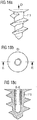
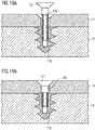
- the at least one fastener component comprising a thread can also have a (partial) inner thread for fixing the bolt as exemplified in Figures 18 and 19 .
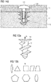
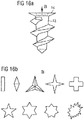
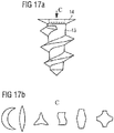
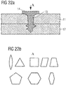
- the head and the slots in the head of the fastener can have different forms as shown in Figures 8 , 13 , 14 , 15-17 , e.g., biangle, triangle, square, pentagon, hexagon and polygons as well as star-shaped forms and mixtures thereof.
- Said at least one component can be screwed into all components which are positioned on top of each other, or to be screwed only into the bottom component and optionally further components, but not into the top component(s).
- Step (d) comprises drilling the fastener into the components by applying a torque and optionally a pressure force towards the positions, where the components are to be joined.
- the joined components are allowed to cool to ambient temperature, e.g., a temperature in the range of from 15 to 25°C.
- ambient temperature e.g., a temperature in the range of from 15 to 25°C.
- the cooling process can be enhanced by applying cooling techniques.
- the thermoplastic fiber composite component can include a thermoplastic material selected from the group consisting of polyamide (PA), polyphenylene sulfide (PPS), polyetherketoneketone (PEKK), polyetheretherketone (PEEK), polypropylene (PP), polyethylene (PE), poly(styrene-butadiene-styrene) (SBS) and polyethyleneimine (PEI), preferably polyphenylene sulfide (PPS), and polyetherketoneketone (PEKK), polyetheretherketone.
- a thermoplastic material selected from the group consisting of polyamide (PA), polyphenylene sulfide (PPS), polyetherketoneketone (PEKK), polyetheretherketone (PEEK), polypropylene (PP), polyethylene (PE), poly(styrene-butadiene-styrene) (SBS) and polyethyleneimine (PEI), preferably polyphenylene sulfide (PPS), and polyetherketoneketone (PE
- thermoplastic fiber composite component can be prepared by applying methods known in the art, e.g., by forming prepregs and curing same by applying heat and/or pressure. Other methods include press-forming, maybe even with stringers, consolidation in autoclave, consolidation on oven, and In-Situ consolidation (e.g., by laser, plasma, resistance heating).
- the reinforcement fibers may be carbon fibers or glass fibers, high resistance modulus carbon fibre, e.g., AS, IM, HM, E Glass, T300, T800, and HS.
- thermoplastic material includes thermoplastic polymers, or a mixture of thermoplastic polymers with elastomers and/or thermoset polymers.
- the at least one of the thermoplastic fiber composite components preferably represents a carbon-fiber-reinforced plastic (CFRP) material.
- the reinforcement fibers may be present as uni-directional layer(s), as fabrics or as laid webs.
- the matrix surrounding the reinforcement fibers can be cured by using temperature and pressure. Frequently a pultrusion process is applied, which is a continuous process for manufacture of fiber-reinforced composite materials.
- the matrix may, for example, comprise a material that can be liquefied through heating.
- the reinforcement fibers may be in form of laminates, tubes or tapes.
- the reinforcement fibers are present as tapes. These tapes may originate from spools which were used in an upstream manufacturing process and on which remainder material of reinforcement fibers is present, which would be disposed. This remainder material can be utilized in the preparation of bulk moulding compounds and sheet moulding compounds and thus in the production of composite materials.
- the one or more components can, e.g., have a flat form at least at the positions where they are to be joined to each other, and are stacked over each other in step (b), preferably, the components have a thickness of up to 20 mm, preferably up to 4 mm.
- the components can, e.g., have a panel or sheet form.
- the head of a screw can for example be a countersink head, a spherical head, or a polyhedron head (see Figures 8a-8c ).
- the thread can be dimensioned to be in all components which are positioned on top of each other, or to be only in the bottom component(s) leaving an unthreaded part at least in the top component(s) (see Figures 9a-9c ).
- the fastener can extend through all components and can protrude beyond the joined components (see Figures 10a-10c ).
- Said fastener or said further component can comprise a head at one end and an opposing end which can be deformed.
- the fastener can be inserted in a one sided process (i.e. inserted from one side of the components which are positioned on top of each other) without requiring manipulating from another side, such as used with a blind fastener (see Figures 12a and 12b ).
- the blind fastener comprises at least one component comprising a thread and a bolt to be inserted into said at least one component comprising a thread.
- the fastener can also be inserted by using a two sided process by inserting the fastener as in step (d) and providing a further component for securing the fastener at the opposing side.
- the method does not include drilling of a hole into the components prior to or during step (d), or at least does not include drilling of a hole into the thermoplastic fiber composite component(s) prior to or during step (d).
- the method does not comprise using a drilling device for forming a hole, at least not a through hole, into the components to be joined. Applying holes at the surface for marking purposes can nevertheless be performed.
- the fastener has no cutting edges, in particular no cutting edges at its tip or side parts, e.g., at the thread, which could drill a hole during step (d), i.e. during the insertion of the fastener.
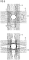
- Such an embodiment is preferred, since the fastener is inserted by shifting/moving the fibers aside ( Fig. 6b ) without (significantly) cutting the fibers, in contrast to a cutting of fibers like in conventional drilling ( Fig. 6a ).
- the joined components are preferably components of a vehicle, such as an aircraft, a spacecraft, a train, a bus or a passenger ship/vessel.
- the joined components are particularly preferred components of an aircraft or spacecraft, and/or are selected from the group consisting of: skin, e.g., skin panel; stiffening elements such as circumferential stiffeners (frames) and/or stringers, doublers/ reinforcements, window frames, floor structure components, such as cross beams, seat rails, Z-struts, X-paddels; door frames, intercostals, lintel and a mix of different parts thereof.
- skin e.g., skin panel
- stiffening elements such as circumferential stiffeners (frames) and/or stringers, doublers/ reinforcements, window frames
- floor structure components such as cross beams, seat rails, Z-struts, X-paddels
- door frames intercostals, lintel and a mix of different parts thereof.
- the number of joined components can for example be at least two, e.g., two, or at least three, e.g., three.
- the components can be made of the same material or can be made of a different material.
- the component which is not a thermoplastic fiber composite component can be made of plastic or metal.
- the present invention also refers to the use of heat for softening a thermoplastic fiber composite component during screwing of a fastener comprising a thread into one or more components, wherein at least one of said one or more components is said thermoplastic fiber composite component.
- the use can include all features described in the context of the method of the invention herein.
- the present invention further refers to a joined-together component(s) including a fiber composite component, preferably of a vehicle, aircraft or spacecraft, obtainable or obtained by the method of the present invention as described herein.
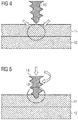
- Figures 1-5 show the fastener 13 in the form of a screw.
- the screw has been brought into position, i.e. is positioned above the components at the location where these are to be joined.
- Components 11 and 12 have been positioned on top of each other.
- the use of a single component which is bent or folded to prove an overlapping section can provide the same setup as shown in Figures 1-5 .
- Figure 6 shows the difference between prior art drilling methods ( Figure 6a ) and the method of the present invention ( Figure 6b ).
- Figure 6a shows the difference between prior art drilling methods
- Figure 6b shows the method of the present invention
- Figure 6b shows the structural differences between prior art products and the products of the present invention, resulting from the processes of joining according to the invention. These differences may be determined by microscopy, e.g. scanning electron microscopy.
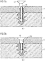
- Figures 7a and 7b show two components 11 and 12, to be joined by a bolt and insert combination.
- Component 11 is joined with component 12 by inserting bolt 120 (i.e. a further component which can optionally also comprise a thread) into the insert 113.
- the bolt can be screwed or hammered into the insert.
- Figures 11a and 11b show an embodiment which is similar to the embodiment of Figures 7a and 7b . However, in Figures 11a and 11b , the threaded component 113 protrudes beyond the components.
- PPS polyphenylene sulfide
- This material is used in A350 clips and cleats.
- the material PPS had a melting temperature of about 285°C.
- a woodscrew having a length of 16 mm and a cross recess was inserted by using a manual screwdriver and a blowtorch for heating.
- the temperature of the sheet was controlled by distance temperature measurement by means of IR measurement with laser steering (range: -50°C up to 900°C). Upon heating to a temperature of about 200°C it was possible to screw with minimal forces without destroying the fibers. After removal of the screw a god quality of the holes were observed.
Landscapes
- Engineering & Computer Science (AREA)
- Mechanical Engineering (AREA)
- General Engineering & Computer Science (AREA)
- Physics & Mathematics (AREA)
- Thermal Sciences (AREA)
- Aviation & Aerospace Engineering (AREA)
- Life Sciences & Earth Sciences (AREA)
- Chemical & Material Sciences (AREA)
- Dispersion Chemistry (AREA)
- Wood Science & Technology (AREA)
- Connection Of Plates (AREA)
- Lining Or Joining Of Plastics Or The Like (AREA)
Abstract
Description
- The present invention refers to a method for joining together different components or different sections of a single component, wherein at least one of the components is a thermoplastic fiber composite component, by using a fastener, wherein heat is applied to soften the thermoplastic fiber composite component. The invention further refers to the use of heat for joining together said component(s) by using a fastener. The invention also refers a joined-together fiber composite component of a vehicle, aircraft or spacecraft, obtainable or obtained by the method of the invention.
- In aircraft construction, efforts are being made to use, as load-bearing components, components that are made entirely or partially of fiber reinforced composite materials, for example carbon fiber reinforced plastics (CFRP). It is further known to provide aircraft fuselage segments with a skin and reinforcing elements (for example frames, stringers) made of fiber reinforced composite materials. These components can be joined, i.e. fixed together or mounted, by using bolts, nuts, screws and/or similar fasteners.
- The reinforced composite materials are often thermoplastic fiber composite components. Thermoplastic connections are known and are generally realized by fusing/welding the layers to be joined. Compared with thermosets, thermoplastics generally have poorer behavior with respect to creep, this being of significance particularly in aircraft construction.
- Fastening of fiber composite components via drilled holes has several disadvantages. Structural disadvantages of drilled holes are that the fibers are cut during the drilling process and that there is a risk of delamination of the composite material. There are also manufacturing issues, since such a process requires a complex process chain with different operations. Furthermore, carbon dust is created and there is a need of sealant for hermetisation as well as a long lead time in case of shimming.
- Self-piercing rivets (SPR) also have disadvantages. Structural disadvantages are that they are applicable only for metallic materials and there is a risk of crack formation and reduction of fatigue behaviour. Also manufacturing issues exist such as needs of sealant for hermetisation.
- Likewise, thermoplastic welding has structural disadvantages such as low mechanical behaviors, because of no connection between fibers in different parts. Also manufacturing issues exist, such as the need of high pressure over complete joining area and a high temperature over complete joining area.
- There was therefore a need to reduce the efforts involved in the assembly of components, including a thermoplastic fiber composite component. Also a need for improved stability of the joints existed.
- The present invention solves the posed problem by providing a method for joining together components, wherein the method comprises a step of heating at least the component which is a thermoplastic fiber composite material while a fastener is screwed into said component. Further features and benefits are described below.
- The present invention provides several benefits over the know methods. First of all, compared to the welding method, it is only required to locally apply a high temperature instead of having to heat the whole components. The method of the present invention can be used if just one of the components to be joined is a thermoplastic fiber composite material, i.e. a fastener comprising a thread can be inserted into said thermoplastic fiber composite material by using heat and providing the benefits of the invention. The method of the present invention does not require to drill holes prior to or during insertion of the fastener, but can rely on self-drilling principles. However, it is of course possible to drill through holes into the components which are not thermoplastic fiber composite materials and apply the method of the present invention without drilling holes into the thermoplastic fiber composite components.
- The joints obtained by the method of the present invention provide an increased strength compared with thermoplastic welding. In the method of the present invention, the thread of the fastener moves the fibers and thermoplastic material of the heat softened thermoplastic fiber composite aside. Compared with a drilled hole, the fibers are not cutted in this case. Since the present invention avoids cutting of the fibers, the fibers essentially remain continuous. The presence of continuous fibers around the fastener further increases the performance of the joint. The method is also applicable to thermoplastic materials reinforced with short fibers and nanoparticles. The core of the present invention refers to the use of a fastener with a thread within the thermoplastic composite component and the remaining part of the fastener, or further components, e.g. bolts, for fixing the fastener, can be chosen to provide further benefits. For example, the end of the fastener can be fixed by deformation or can be fixed by using a fastener head. It is also possible to use blind fasteners or other principles and many options for putting the invention into practice can be used.
- The present invention thus refers to a method for joining together different components or different sections of a single component, comprising the steps of:
- a) providing one or more components, wherein at least one of the components is a thermoplastic fiber composite component, preferably reinforced with short fibers, and/or continuous fibers, and/or nanoparticles, preferably including continuous fibers, including a thermoplastic material, optionally, to be joined together at one or more positions, and a fastener comprising a thread, or at least one component of a fastener, which component comprises a thread,
- b) positioning said one or more components, or sections of the single component on top of each other,
- c) heating at least a portion of the at least one thermoplastic fiber composite component, and optionally also portions of the other components to be joined, at one or more positions where the components are to be joined and/or
heating said fastener or said at least one component of a fastener, and - d) drilling said fastener, or said at least one component of a fastener, into at least the bottom component at the one or more positions,
- Step (a) includes providing the components and fastener. The term "thermoplastic fiber composite component" as used herein refers to a component comprising or consisting of fibers embedded in a polymer matrix. The term "component" refers to any 3-dimensional structure/article which is to be joined with another structure/article, e.g., a panel, by means of a fastener. Preferred components are described further below. The polymer matrix of the fiber composite includes or consists of a thermoplastic material. The term "thermoplastic fiber composite component" is the same as fiber reinforced composite materials.
- In one embodiment, the thermoplastic fiber composite component comprises, preferably consists of, more than 0 wt.-% and up to 80 wt.-% of fibers and/or nanoparticles, preferably continuous fibers, and from 20 wt.-% to less than 100 wt.-% of thermoplastic material.
- Preferably, the thermoplastic fiber composite component comprises, preferably consists of, 10 wt.-% to 70 wt.-%, preferably 30 wt.-% to 65 wt.-%, or 45 wt.-% to 65 wt.-% of fibers and/or nanoparticles, preferably continuous fibers, and 30 wt.-% to 90 wt.-%, preferably at least 35 wt.-% to 70 wt.-%, or 35 wt.-% to 60 wt.-%, or 35 wt.-% to 50 wt.-%, of thermoplastic material. In one embodiment, the thermoplastic fiber composite component comprises, preferably consists of 55 wt.-% to 65 wt.-% of fibers and/or nanoparticles, preferably continuous fibers, and 35 wt.-% to 45 wt.-% of thermoplastic material. The thermoplastic material can, e.g., have a glass transition temperature of above 80° C.
- In one embodiment, the thermoplastic fiber composite component comprises, preferably consists of, about 60 wt.-% of continuous fibers and about 40 wt.-% of thermoplastic material, wherein the thermoplastic material optionally includes short fibers and/or nanoparticles.
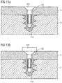
- The other components, i.e. the components which are not thermoplastic fiber composite components, can be freely chosen provided that they can be fixed with a fastener. In the process described herein, the components are positioned on top of each other. If one component is used, it can be bend or folded to have overlapping sections. If one or more bottom component(s) are made of a thermoplastic fiber composite component, this/these can be used for inserting a fastener comprising a thread. It is possible that this fastener either extends also into the other components or the other components are fixed to said fastener by using a further component, e.g., a bolt. To insert said bolt, it is an option to provide through holes into the other components and to fix the fastener by means of said bolt wherein the bolt then extends through all components (see e.g.,
Figure 13a/b ). It is also possible that both the fastener with the thread and the bolt extend through all components (see e.g.,Figure 12a/b ). - Step (b) includes positioning of the component(s). If a single component is to be joined with itself, different sections of said component are joined with each other. For example, a flat sheet can be formed into a tube and overlapping portions of the flat sheet can be joined together. Positioning the components on top of each other does not exclude the use of spacers, sandwiched components which are not fixed, or leaving voids between the components.
- Heating step (c) is applied to soften the thermoplastic material. The required temperature therefore depends on how soft the thermoplastic material shall become and further depends on the glass transition temperature of the material. Suitable temperatures should be higher than the glass transition temperature but below the melting temperature and can be determined as process parameters depending on the applied materials, fasteners and equipment.
The glass transition temperature (Tg) is one specific thermophysical property of amorphous polymers. The glass transition is a complex process for thermoplastic materials that is affected by a number of different factors, including fiber volume content, heating rate, ageing history, morphology, etc.
Glass transition temperature (Tg) is a temperature where a polymer begins to exhibit a reduction in modulus.TP material Glass transition temperature Tg (°C) Melting temperature Tm (C°) PPS 90-95 278 - 290 PEI 210 360 PEEK 156 310 PEKK 143 343 - For example, it is possible for materials with PPS resin to heat the fastener to a temperature of at least 100°C and/or the thermoplastic fiber composite component to a temperature of at least 90°C, or at least 120°C, or at least 150°C. Temperatures where the properties of the thermoplastic materials are degraded should be avoided. It should also be avoided to completely melt the polymer, i.e. the softening temperature should be well below the melting point of the thermoplastic material. For example, an upper limit for the temperature of the fastener for materials with PPS resin is 285°C and is 285°C for the thermoplastic fiber composite component.
- The heating in step (c) can for example be performed with ultrasound, hot air, microwave radiation, laser radiation, electric current, electromagnetic induction and/or IR radiation. In particular, inner parts can be heated by ultrasound, hot air, microwave radiation, laser radiation, electromagnetic induction and/or IR radiation. The fastener, preferably metallic fastener, can e.g., be heated by applying electric current. The aim of heating the fastener and/or the component (at the position where the fastener is to be inserted/screwed into) is to soften the polymeric material, in particular to the effect that the fastener moves aside the polymeric material and fibers without cutting and removing same like in a drilling method. As with the temperature which is required for softening, a skilled person can also determine the minimum area of the surface or inner part of the components in order that the fastener can be screwed into the component(s) as desired.
- Accordingly, the heating is preferably performed at one surface or opposing surfaces of the one or more components, which are positioned on top of each other, at positions where the components are to be joined. Of course, heating the surfaces provides that the inner part is also (indirectly) heated. In a preferred embodiment, a homogenous temperature profile is provided in the heated component with the highest temperature at the positions for insertion of the fasteners and about the same temperature along the axis for insertion of the fasteners. It is also possible to modify the temperature profile in dependence of the form of the thread with greater diameters requiring a softer polymer, i.e. higher temperature. For example, if the component(s) is/are heated only on the surface of one side, there will be a temperature gradient along the axis of insertion.
- It is also possible to heat at an inner part of one or more of said one or more components which are to be joined. That is, the energy input or at least its maximum is not located at a surface of the component(s) but is located in the inner part.
- The components are preferably placed in contact which each other at least at the positions where they are joined together. Subsequently, prior to or after step (c), the fasteners are positioned at the one or more positions where the component(s) shall be jointed. This positioning can be performed by applying holes, marker and any other principles for allowing a quick positioning. This means that it is possible to heat the fasteners and/or the components and then bring the fasteners in position for screwing, or it is possible to first bring the fasteners in position for screwing and then heat the fasteners and/or the components.
- Fixing the further component to the at least one component comprising a thread can e.g., be performed by riveting or boltening said further component of the fastener to the at least one component of the fastener comprising a thread.
- In step (d), the fastener is drilled into at least one component (or section of one component), e.g. one component (or section), several components (or sections), or all components (sections). In one embodiment, the fastener is drilled into all components which are positioned on top of each other.
- If the fastener is made of a single component, e.g., a screw, the fastener has to extend through all components to join them, while one or more components can have a through hole before the fastener is inserted. However, it is preferred that the thermoplastic composite components do not have a through hole. If the fastener is made of one component, e.g., a screw, the fastener is drilled into all components and fixing is then either completed or (a) further step(s) is/are required such as deforming the end of the fastener which is protruding beyond the components.
- The fastener can also consist of more than one component, e.g., two components, which act together to fix the components. In such an embodiment, at least one component of a fastener, which component comprises a thread, is screwed into the component(s). This is preferably done in one or more bottom components. The components are positioned on top of each other and the bottom component is the outermost component and the at least one component comprising a thread is screwed into the bottom component with the tip of the screw pointing in a direction opposite to the other components.
- If the fastener consists of more than one component, e.g., two components, which act together to fix the components, at least one component of a fastener, which component comprises a thread, is screwed into the component(s) and a further component is used for engaging with said component to fix the fastener. For example, a nut or a bolt can be used as the further component. The nut can be put on the component comprising a thread to fix the fastener. A bold can be inserted into the component comprising a thread to, e.g., form a rivet joint.
- Accordingly, the fastener can be a screw, said at least one component of a fastener, which comprises a thread, can be an insert of a rivet, e.g., of a drive rivet or a blind rivet, and said at least further component can be a bolt. The fastener can be used for permanent fixation or can be made removable. Removing the fastener may again require applying heat to soften the thermoplastic material.
- In general, the components are not welded together by the process of the present invention. However, if two thermoplastic components are joined together, they may bond together (by welding) at the positions where they are heated in step c).
- The fastener comprising a thread is configured for applying a pressure force and/or torque for screwing. This can be done by using methods and devices known in the art. The fastener, said at least one component of a fastener and said further component of a fastener is predominantly made of a metal or a metal alloy. Suitable materials are the same as used in common screw and rivet applications.
Suitably, also fasteners produced from materials with reinforcements with fibers or nanoparticles can be used. Also various ceramic materials can be used as fasteners. Also fasteners produced from polymeric materials with Tg higher than Tg of the materials to be joined can be used. As an example, fasteners produced with PEKK resin can be used for joining of thermoplastic materials with PPS resin. - The thread of said fastener, or of said at least one component can be dimensioned to be in all components, i.e. extend through all components when the fastener is in its final position, which components are positioned on top of each other, or can be dimensioned to be present only in the bottom component and optionally further components, but not in the top component(s), leaving an unthreaded part at least in said top component(s). The at least one fastener component comprising a thread can also have a (partial) inner thread for fixing the bolt as exemplified in
Figures 18 and19 . - The head and the slots in the head of the fastener can have different forms as shown in
Figures 8 ,13 ,14 ,15-17 , e.g., biangle, triangle, square, pentagon, hexagon and polygons as well as star-shaped forms and mixtures thereof. - Said at least one component can be screwed into all components which are positioned on top of each other, or to be screwed only into the bottom component and optionally further components, but not into the top component(s).
- Step (d) comprises drilling the fastener into the components by applying a torque and optionally a pressure force towards the positions, where the components are to be joined. After step (d), the joined components are allowed to cool to ambient temperature, e.g., a temperature in the range of from 15 to 25°C. The cooling process can be enhanced by applying cooling techniques.
- The thermoplastic fiber composite component can include a thermoplastic material selected from the group consisting of polyamide (PA), polyphenylene sulfide (PPS), polyetherketoneketone (PEKK), polyetheretherketone (PEEK), polypropylene (PP), polyethylene (PE), poly(styrene-butadiene-styrene) (SBS) and polyethyleneimine (PEI), preferably polyphenylene sulfide (PPS), and polyetherketoneketone (PEKK), polyetheretherketone.
- The thermoplastic fiber composite component can be prepared by applying methods known in the art, e.g., by forming prepregs and curing same by applying heat and/or pressure. Other methods include press-forming, maybe even with stringers, consolidation in autoclave, consolidation on oven, and In-Situ consolidation (e.g., by laser, plasma, resistance heating).
- The reinforcement fibers may be carbon fibers or glass fibers, high resistance modulus carbon fibre, e.g., AS, IM, HM, E Glass, T300, T800, and HS.
- The thermoplastic material includes thermoplastic polymers, or a mixture of thermoplastic polymers with elastomers and/or thermoset polymers. The at least one of the thermoplastic fiber composite components preferably represents a carbon-fiber-reinforced plastic (CFRP) material.
- The reinforcement fibers may be present as uni-directional layer(s), as fabrics or as laid webs. For the manufacture of a composite material component from a semifinished composite material, the matrix surrounding the reinforcement fibers can be cured by using temperature and pressure. Frequently a pultrusion process is applied, which is a continuous process for manufacture of fiber-reinforced composite materials. The matrix may, for example, comprise a material that can be liquefied through heating. The reinforcement fibers may be in form of laminates, tubes or tapes. Preferably, the reinforcement fibers are present as tapes. These tapes may originate from spools which were used in an upstream manufacturing process and on which remainder material of reinforcement fibers is present, which would be disposed. This remainder material can be utilized in the preparation of bulk moulding compounds and sheet moulding compounds and thus in the production of composite materials.
- The one or more components can, e.g., have a flat form at least at the positions where they are to be joined to each other, and are stacked over each other in step (b), preferably, the components have a thickness of up to 20 mm, preferably up to 4 mm. The components can, e.g., have a panel or sheet form.
- If a rivet is used, it can be called a "hot joint rivet". The head of a screw can for example be a countersink head, a spherical head, or a polyhedron head (see
Figures 8a-8c ). The thread can be dimensioned to be in all components which are positioned on top of each other, or to be only in the bottom component(s) leaving an unthreaded part at least in the top component(s) (seeFigures 9a-9c ). The fastener can extend through all components and can protrude beyond the joined components (seeFigures 10a-10c ). - Said fastener or said further component can comprise a head at one end and an opposing end which can be deformed. This means that the fastener can be inserted in a one sided process (i.e. inserted from one side of the components which are positioned on top of each other) without requiring manipulating from another side, such as used with a blind fastener (see
Figures 12a and 12b ). The blind fastener comprises at least one component comprising a thread and a bolt to be inserted into said at least one component comprising a thread. The fastener can also be inserted by using a two sided process by inserting the fastener as in step (d) and providing a further component for securing the fastener at the opposing side. - In one embodiment, which can be combined with all aspect described herein, the method does not include drilling of a hole into the components prior to or during step (d), or at least does not include drilling of a hole into the thermoplastic fiber composite component(s) prior to or during step (d).
- In such an embodiment, the method does not comprise using a drilling device for forming a hole, at least not a through hole, into the components to be joined. Applying holes at the surface for marking purposes can nevertheless be performed. Furthermore, the fastener has no cutting edges, in particular no cutting edges at its tip or side parts, e.g., at the thread, which could drill a hole during step (d), i.e. during the insertion of the fastener. Such an embodiment is preferred, since the fastener is inserted by shifting/moving the fibers aside (
Fig. 6b ) without (significantly) cutting the fibers, in contrast to a cutting of fibers like in conventional drilling (Fig. 6a ). - The joined components are preferably components of a vehicle, such as an aircraft, a spacecraft, a train, a bus or a passenger ship/vessel. The joined components are particularly preferred components of an aircraft or spacecraft, and/or are selected from the group consisting of: skin, e.g., skin panel; stiffening elements such as circumferential stiffeners (frames) and/or stringers, doublers/ reinforcements, window frames, floor structure components, such as cross beams, seat rails, Z-struts, X-paddels; door frames, intercostals, lintel and a mix of different parts thereof.
- The number of joined components can for example be at least two, e.g., two, or at least three, e.g., three. The components can be made of the same material or can be made of a different material. The component which is not a thermoplastic fiber composite component can be made of plastic or metal.
- The present invention also refers to the use of heat for softening a thermoplastic fiber composite component during screwing of a fastener comprising a thread into one or more components, wherein at least one of said one or more components is said thermoplastic fiber composite component. The use can include all features described in the context of the method of the invention herein.
- The present invention further refers to a joined-together component(s) including a fiber composite component, preferably of a vehicle, aircraft or spacecraft, obtainable or obtained by the method of the present invention as described herein.
- Preferred embodiments of the method, use and joined components of the present invention are described in greater detail with reference to the attached schematic drawings in the following.
- Figure 1
- shows the joined together
component 10, wherein afastener 13 is screwed intocomponents - Figure 2
- shows the embodiment of
Figure 1 after thefastener 13 is positioned but before it is drilled intocomponents - Figure 3
- shows the embodiment of
Figures 1 and 2 , whereinfastener 13 is heated before and optionally during drilling intocomponents components fastener 13. - Figure 4
- shows the embodiment of
Figures 1-3 , wherein an inner part ofcomponents 11 and 12 (indicated by the arrows) is heated at positions wherecomponents - Figure 5
- shows the embodiment of
Figures 1-4 , wherein a pressure force is applied onto thehead 14 of thefastener 13 towards the position where the components are to be joined (indicated by the arrow which is perpendicular tocomponents 11 and 12), and wherein a torque/momentum force is applied to fastener 13 (indicated by the bent arrow). - Figure 6a
- shows an enlarged view on a thermoplastic fiber composite component after conventional drilling, wherein a drilled hole/through
hole 17 has been formed.Composite fibers fibers 18 remain. - Figure 6b
- shows an enlarged view on a thermoplastic fiber composite component after a fastener has been screwed into it, wherein moved
fibers 19 remain, which are still (essentially) continuous, i.e. are not cut but are pushed aside by the fastener (not shown). - Figure 7a
- shows two
components component 12. The bolt has not yet been fully inserted. - Figure 7b
- shows the embodiment of
Figure 7 , wherein thebolt 120 has been fully inserted. - Figure 8a
- shows a fastener in the form of a
screw 13 with acountersink head 14, wherein the thread is in bothcomponents - Figure 8b
- shows a fastener in the form of a
screw 13 with aspherical head 14, wherein the thread is in bothcomponents - Figure 8c
- shows a fastener in the form of a
screw 13 with apolyhedron head 14, wherein the thread is in bothcomponents - Figure 9a
- shows a fastener in the form of a
screw 13 with acountersink head 14 and a thread only incomponent 12. - Figure 9b
- shows a fastener in the form of a
screw 13 with apolyhedron head 14 and a thread only incomponent 12. - Figure 9c
- shows a fastener in the form of a
screw 13 with aspherical head 14 and a thread only incomponent 12. - Figure 10a
- shows a fastener in the form of a
screw 13 with acountersink head 14, wherein thescrew 13 goes through bothcomponents - Figure 10b
- shows the embodiment of
Figure 10a with apolyhedron head 14. - Figure 10c
- shows the embodiment of
Figure 10a with aspherical head 14. - Figure 11a
- shows two
components component 113 of the fastener comprising a thread is screwed intocomponent 12 to join it withcomponent 11 by insertingbolt 120, which is not yet fully inserted (i.e. a further component of the fastener not comprising a thread), wherein the threadedcomponent 113 protrudes beyond the components. - Figure 11b
- shows the embodiment of
Figure 11a , wherein thebolt 120 has been fully inserted. - Figure 12a
- shows two
components component 113 of the fastener comprising a thread which is screwed intocomponents - Figure 12b
- shows the embodiment of
Figure 12a , wherein thebolt 120 has been fully fixed. - Figure 13a
- shows a fastener with two components, wherein one
component 113 comprises a thread and is screwed into thebottom component 12, and afurther component 120 which is a bolt with acountersink head 121. - Figure 13b
- shows the embodiment of
Figure 13a with aspherical head 121. - Figure 13c
- shows the embodiment of
Figure 13a with apolyhedron head 121. - Figure 14a
- shows a fastener (insert) 113 which is screwed into
component 12 and is fixed with abolt 120 having acountersink head 121. - Figure 14b
- shows the embodiment of
Figure 14a with adifferent head 121 and bolt 120 variant. - Figure 14c
- shows the embodiment of
Figure 14a with adifferent head 121 and bolt 120 variant. - Figure 14d
- shows the embodiment of
Figure 14a with adifferent head 121 and bolt 120 variant. - Figure 15a
- shows a
fastener 13, wherein arrow A shows the slot(s) in thefastener head 14. - Figure 15b
- shows different slot variants/forms of
head 14 ofFigure 15a , i.e. biangle, triangle, square, pentagon, hexagon and polygon. - Figure 16a
- shows a
fastener 13, wherein arrow B shows the slot(s) in thefastener head 14. - Figure 16b
- shows different slot variants/star forms of
head 14 ofFigure 16a . - Figure 17a
- shows a
fastener 13, wherein arrow C shows the slot(s) in thefastener head 14. - Figure 17b
- show different slot variants/ forms, being a mix of the forms of
head 14 ofFigures 15 and16 . - Figure 18a
- shows a
fastener 113, wherein arrow D shows the location of a partial inner thread at the location. - Figure 18b
- shows the top view of
Figure 18a on the partial inner thread. - Figure 18c
- shows a cross-section of the
fastener 113 ofFigures 18a and 18b . - Figure 19a
- shows a cross-section of
fastener 113 ofFigures 18a-18c with abolt 120 before being fully inserted. - Figure 19b
- shows the embodiment of
Figure 19a with thebolt 120 being fully inserted. - Figure 20a
- shows a
fastener 113, wherein arrow F shows the location of an inner thread at the location. - Figure 20b
- shows the top view of
Figure 20a on the inner thread. - Figure 20c
- shows a cross-section of
fastener 113 ofFigures 20a and 20b . - Figure 21a
- shows a cross-section of the
fastener 113 ofFigures 20a-20c with abolt 120 before being fully inserted. - Figure 21b
- shows the embodiment of
Figure 21a with thebolt 120 being fully inserted. - Figure 22a
- shows a
fastener 13 inserted in components 1 and 2 with ahead 14, pointed to by arrow A. - Figure 22b
- shows different head variants/forms, i.e. biangle, triangle, square, pentagon, hexagon and polygon of
head 14 ofFigure 22a . - Figure 23a
- shows a
fastener 13 inserted in components 1 and 2 with ahead 14, pointed to by arrow B. - Figure 23b
- shows different head variants/ star forms of
head 14 ofFigure 23a . - Figure 24a
- shows a
fastener 13 inserted in components 1 and 2 with ahead 14, pointed to by arrow C. - Figure 24b
- shows different head variants/forms based on mixtures of the forms of
head 14 ofFigures 22 and23 . - Figure 25
- shows a prior art self-piercing rivet.
- Figure 26a
- shows a prior art fastener with cutting edges which is inserted into a component, thereby forming a through hole.
- Figure 26b
- shows a prior art fastener showing that the cutting edges are removed/not present according to the present application.
- The following detailed description of the schematic drawings focuses on the illustrated implementation variants of a method of the invention, the use of the invention and the joined-together components of the invention. The present disclosure is not limited to the above and below described embodiments, but includes combinations thereof.
-
Figures 1-5 show thefastener 13 in the form of a screw. InFigure 2 , the screw has been brought into position, i.e. is positioned above the components at the location where these are to be joined.Components Figures 1-5 . -
Figure 6 shows the difference between prior art drilling methods (Figure 6a ) and the method of the present invention (Figure 6b ). When comparing the figures, the structural differences between prior art products and the products of the present invention, resulting from the processes of joining according to the invention, become apparent. These differences may be determined by microscopy, e.g. scanning electron microscopy. -
Figures 7a and 7b show twocomponents Component 11 is joined withcomponent 12 by inserting bolt 120 (i.e. a further component which can optionally also comprise a thread) into theinsert 113. The bolt can be screwed or hammered into the insert. -
Figures 11a and 11b show an embodiment which is similar to the embodiment ofFigures 7a and 7b . However, inFigures 11a and 11b , the threadedcomponent 113 protrudes beyond the components. - A test was performed with PPS (polyphenylene sulfide) material. This material is used in A350 clips and cleats. The material PPS had a melting temperature of about 285°C. A woodscrew having a length of 16 mm and a cross recess was inserted by using a manual screwdriver and a blowtorch for heating. The temperature of the sheet was controlled by distance temperature measurement by means of IR measurement with laser steering (range: -50°C up to 900°C). Upon heating to a temperature of about 200°C it was possible to screw with minimal forces without destroying the fibers. After removal of the screw a god quality of the holes were observed.
-
- 10
- joined-together components
- 11
- component to be joined
- 12
- component to be joined
- 13
- fastener comprising a thread
- 14
- fastener head
- 15
- composite fiber
- 16
- composite fiber
- 17
- drilled hole/through hole
- 18
- cut fibers
- 19
- moved fibers
- 113
- fastener in form of a threaded insert
- 120
- bolt
- 121
- bolt head
to join the component(s) together,
wherein step (c) can be performed prior to and/or during step (d).
Claims (15)
- A method for joining together different components (11, 12) or different sections of a single component (11, 12), comprising the steps of:a) providing one or more components (11, 12), wherein at least one of the components (11, 12) is a thermoplastic fiber composite component, to be joined together at one or more positions, and a fastener (13) comprising a thread, or at least one component (113) of a fastener, which component comprises a thread,b) positioning said one or more components (11, 12), or sections of the single component (11, 12), on top of each other,c) heating at least a portion of the at least one thermoplastic fiber composite component, and optionally also portions of the other components to be joined, at one or more positions where the components are to be joined and/or
heating said fastener (13) or said at least one component (113) of a fastener, andd) drilling said fastener (13), or said at least one component of a fastener (113), into at least the bottom component (12) at the one or more positions,wherein step (c) can be performed prior to and/or during step (d).
wherein a further component (120) of a fastener is fixed to said at least one component of a fastener (113),
to join the component(s) (11, 12) together, - The method according to claim 1, wherein the thermoplastic fiber composite component includes a thermoplastic material selected from the group consisting of polyamide (PA), polyphenylene sulfide (PPS), polyetherketoneketone (PEKK), polyetheretherketone (PEEK), polypropylene (PP), polyethylene (PE), poly(styrene-butadiene-styrene) (SBS), polyethyleneimine (PEI), preferably polyphenylene sulfide, polyetherketoneketone, and polyetheretherketone, and/or the thermoplastic fiber composite component comprises continuous fibers.
- The method according to claim 1 or 2, wherein said fastener (13), said at least one component (113) of a fastener and said further component (120) of a fastener is predominantly made of a metal or a metal alloy.
- The method according to any preceding claim, wherein said one or more components (11, 12) have a flat form at least at the positions where they are to be joined to each other, and are stacked over each other in step (b), preferably, the components have a thickness of up to 20 mm, preferably up to 3 mm.
- The method according to any preceding claim, wherein the heating in step (c) is performed with ultrasound, hot air, microwave radiation, laser radiation, electric current, electromagnetic induction and/or infrared (IR) radiation.
- The method according to any preceding claim, wherein the heating is performed at(i) one surface or opposing surfaces of the one or more components (11, 12), which are positioned on top of each other, at positions where the components (11, 12) are to be joined; and/or(ii) at an inner part of one or more of said one or more components (11, 12) which are to be joined.
- The method according to any preceding claim, wherein(i) said fastener (13) is a screw, said at least one component (113) of a fastener, which comprises a thread, is an insert of a rivet, and said at least further component (120) is a bolt; and/or(ii) the thread of said fastener (13) or of said at least one component (113) can be dimensioned to extend through all components (11, 12) which are positioned on top of each other, or to be only in the bottom component (12) and optionally further components, but not in the top component(s), leaving an unthreaded part at least in said top component(s) (11); and/or(iii) said at least one component (113) is screwed into all components (11, 12) which are positioned on top of each other, or is screwed only into the bottom component (12); and/or(iv) said fastener (13), said at least one component (113) of a fastener and said further component (120) of a fastener extends through all components.
- The method according to any preceding claim, wherein the method does not include drilling of a hole into the components (11, 12) prior to or during step (d), or at least does not include drilling of a hole into the thermoplastic fiber composite component(s) prior to or during step (d).
- The method according to any preceding claim, wherein said fastener (13), or said further component (120) comprises a head (14, 121) at one end and an opposing end which can be deformed.
- The method according to any preceding claim, wherein the thermoplastic fiber composite component or at least one of the thermoplastic fiber composite components represents a carbon-fiber-reinforced plastic material.
- The method according to any preceding claim, wherein the joined components (11, 12) are components of a vehicle, aircraft or spacecraft and/or are selected from the group consisting of: skin, e.g., skin panel; stiffening elements such as circumferential stiffeners (frames) and/or stringers, doublers/ reinforcements, window frames, floor structure components, such as cross beams, seat rails, Z-struts, X-paddels; door frames, intercostals, lintel and a mix of different parts thereof.
- The method according to any preceding claim, wherein the joined components (10) are components of an aircraft or spacecraft.
- The method according to any preceding claim, wherein the number of joined components is at least two.
- Use of heat for softening a thermoplastic fiber composite component during screwing of a fastener comprising a thread into one or more components (11, 12), wherein at least one of said one or more components (11, 12) is said thermoplastic fiber composite component.
- Joined-together components (10), including a fiber composite component, of a vehicle, aircraft or spacecraft, obtainable or obtained by the method according to any of claims 1-13.
Priority Applications (3)
| Application Number | Priority Date | Filing Date | Title |
|---|---|---|---|
| EP16203398.9A EP3332945B1 (en) | 2016-12-12 | 2016-12-12 | Hot joint fastener |
| CN201711284405.2A CN108215226A (en) | 2016-12-12 | 2017-12-07 | Thermal bonding fastener |
| US15/839,268 US10941804B2 (en) | 2016-12-12 | 2017-12-12 | Hot joint fastener |
Applications Claiming Priority (1)
| Application Number | Priority Date | Filing Date | Title |
|---|---|---|---|
| EP16203398.9A EP3332945B1 (en) | 2016-12-12 | 2016-12-12 | Hot joint fastener |
Publications (2)
| Publication Number | Publication Date |
|---|---|
| EP3332945A1 true EP3332945A1 (en) | 2018-06-13 |
| EP3332945B1 EP3332945B1 (en) | 2023-09-13 |
Family
ID=57749656
Family Applications (1)
| Application Number | Title | Priority Date | Filing Date |
|---|---|---|---|
| EP16203398.9A Active EP3332945B1 (en) | 2016-12-12 | 2016-12-12 | Hot joint fastener |
Country Status (2)
| Country | Link |
|---|---|
| US (1) | US10941804B2 (en) |
| EP (1) | EP3332945B1 (en) |
Cited By (1)
| Publication number | Priority date | Publication date | Assignee | Title |
|---|---|---|---|---|
| WO2019081219A1 (en) * | 2017-10-27 | 2019-05-02 | A. Raymond Et Cie | SEMICONDUCTOR FOR THE PRODUCTION OF A FIBER REINFORCED, A FIXING HOLE OR A FASTENING ELEMENT BONDING COMPONENT, COMPONENT AND METHOD FOR PRODUCING A FASTENER ELEMENT |
Families Citing this family (5)
| Publication number | Priority date | Publication date | Assignee | Title |
|---|---|---|---|---|
| US12433772B2 (en) * | 2019-01-29 | 2025-10-07 | Alps South S.R.O. | Interchangeable pump-lock for prosthetic socket and method of use |
| GB2587391A (en) * | 2019-09-26 | 2021-03-31 | Airbus Operations Ltd | Aircraft assembly |
| DE102020201609A1 (en) | 2020-02-10 | 2021-08-12 | Elringklinger Ag | Method for functionalizing a fiber-reinforced plastic component, functional element for functionalizing a fiber-reinforced plastic component, component composite and device for functionalizing a fiber-reinforced plastic component |
| US20220260104A1 (en) * | 2021-02-17 | 2022-08-18 | Prototype Investments, LLC | Vehicle engine carbon fiber head bolt |
| US12151445B2 (en) * | 2022-09-28 | 2024-11-26 | The Boeing Company | Countersinks in thin gauge thermoplastic skins |
Citations (4)
| Publication number | Priority date | Publication date | Assignee | Title |
|---|---|---|---|---|
| JPH05245941A (en) * | 1992-03-06 | 1993-09-24 | Yokohama Rubber Co Ltd:The | Joining method between more than one material |
| EP2025954A1 (en) * | 2007-08-14 | 2009-02-18 | The Boeing Company | Method for fastening components using a composite two-piece fastening system, and the related assembled part |
| US20130273312A1 (en) * | 2012-04-17 | 2013-10-17 | Ford Global Technologies, Llc | Method of Fastening Parts to a Composite Part |
| WO2014036986A1 (en) * | 2012-09-07 | 2014-03-13 | Bayerische Motoren Werke Aktiengesellschaft | Self-drilling and tapping screw for directly screwing together components without pilot holes and component assembly made in this way |
Family Cites Families (3)
| Publication number | Priority date | Publication date | Assignee | Title |
|---|---|---|---|---|
| WO2016063784A1 (en) * | 2014-10-21 | 2016-04-28 | Dic株式会社 | Adhesive tape, method for manufacturing same, article and portable electronic terminal |
| DE102015106563B4 (en) * | 2015-04-28 | 2024-03-21 | Airbus Operations Gmbh | Method for connecting fiber-reinforced structural components |
| DE102015210965A1 (en) * | 2015-06-15 | 2016-12-15 | Ejot Gmbh & Co. Kg | Method for producing a component composite with a connecting element |
-
2016
- 2016-12-12 EP EP16203398.9A patent/EP3332945B1/en active Active
-
2017
- 2017-12-12 US US15/839,268 patent/US10941804B2/en active Active
Patent Citations (4)
| Publication number | Priority date | Publication date | Assignee | Title |
|---|---|---|---|---|
| JPH05245941A (en) * | 1992-03-06 | 1993-09-24 | Yokohama Rubber Co Ltd:The | Joining method between more than one material |
| EP2025954A1 (en) * | 2007-08-14 | 2009-02-18 | The Boeing Company | Method for fastening components using a composite two-piece fastening system, and the related assembled part |
| US20130273312A1 (en) * | 2012-04-17 | 2013-10-17 | Ford Global Technologies, Llc | Method of Fastening Parts to a Composite Part |
| WO2014036986A1 (en) * | 2012-09-07 | 2014-03-13 | Bayerische Motoren Werke Aktiengesellschaft | Self-drilling and tapping screw for directly screwing together components without pilot holes and component assembly made in this way |
Cited By (1)
| Publication number | Priority date | Publication date | Assignee | Title |
|---|---|---|---|---|
| WO2019081219A1 (en) * | 2017-10-27 | 2019-05-02 | A. Raymond Et Cie | SEMICONDUCTOR FOR THE PRODUCTION OF A FIBER REINFORCED, A FIXING HOLE OR A FASTENING ELEMENT BONDING COMPONENT, COMPONENT AND METHOD FOR PRODUCING A FASTENER ELEMENT |
Also Published As
| Publication number | Publication date |
|---|---|
| EP3332945B1 (en) | 2023-09-13 |
| US10941804B2 (en) | 2021-03-09 |
| US20180163769A1 (en) | 2018-06-14 |
Similar Documents
| Publication | Publication Date | Title |
|---|---|---|
| US10941804B2 (en) | Hot joint fastener | |
| JP6962741B2 (en) | Open channel stifuna | |
| CA2888974C (en) | Joining composite components using low temperature thermoplastic film fusion | |
| US9359060B2 (en) | Laminated composite radius filler with geometric shaped filler element and method of forming the same | |
| US10704584B2 (en) | Process for joining fiber composite materials using self-piercing rivets | |
| JP6218323B2 (en) | Machinable composite materials | |
| AU2020201610A1 (en) | Fabrication of composite laminates using temporarily stitched preforms | |
| EP2390514A1 (en) | Method for fastening aircraft components using a composite two-piece fastening system, and so obtained aircraft structure | |
| EP2964451A2 (en) | Forming composite features using steered discontinuous fiber pre-preg | |
| EP3845370B1 (en) | Method of forming composite structural panels | |
| US10005267B1 (en) | Formation of complex composite structures using laminate templates | |
| JP2013540608A5 (en) | ||
| US20170028698A1 (en) | Method for joining thermoset components | |
| US20150210019A1 (en) | Methods for combining components of varying stages of cure | |
| EP3625034B1 (en) | Fastenerless structural assembly | |
| CN108215226A (en) | Thermal bonding fastener | |
| WO2022229197A1 (en) | Main body of an aerial vehicle | |
| EP3403918A1 (en) | Stiffening structure for an aircraft door or panel | |
| EP3403917A1 (en) | Door assembly for a vehicle | |
| EP3403807A1 (en) | Fastenerless structural assembly | |
| US20150093541A1 (en) | Composite staple | |
| Mathai et al. | Joining of Fiber-Reinforced Polymer Composites |
Legal Events
| Date | Code | Title | Description |
|---|---|---|---|
| PUAI | Public reference made under article 153(3) epc to a published international application that has entered the european phase |
Free format text: ORIGINAL CODE: 0009012 |
|
| STAA | Information on the status of an ep patent application or granted ep patent |
Free format text: STATUS: THE APPLICATION HAS BEEN PUBLISHED |
|
| AK | Designated contracting states |
Kind code of ref document: A1 Designated state(s): AL AT BE BG CH CY CZ DE DK EE ES FI FR GB GR HR HU IE IS IT LI LT LU LV MC MK MT NL NO PL PT RO RS SE SI SK SM TR |
|
| AX | Request for extension of the european patent |
Extension state: BA ME |
|
| STAA | Information on the status of an ep patent application or granted ep patent |
Free format text: STATUS: REQUEST FOR EXAMINATION WAS MADE |
|
| 17P | Request for examination filed |
Effective date: 20180823 |
|
| RBV | Designated contracting states (corrected) |
Designated state(s): AL AT BE BG CH CY CZ DE DK EE ES FI FR GB GR HR HU IE IS IT LI LT LU LV MC MK MT NL NO PL PT RO RS SE SI SK SM TR |
|
| STAA | Information on the status of an ep patent application or granted ep patent |
Free format text: STATUS: EXAMINATION IS IN PROGRESS |
|
| 17Q | First examination report despatched |
Effective date: 20201009 |
|
| GRAP | Despatch of communication of intention to grant a patent |
Free format text: ORIGINAL CODE: EPIDOSNIGR1 |
|
| STAA | Information on the status of an ep patent application or granted ep patent |
Free format text: STATUS: GRANT OF PATENT IS INTENDED |
|
| RIC1 | Information provided on ipc code assigned before grant |
Ipc: B29C 65/16 20060101ALN20230609BHEP Ipc: B29C 65/14 20060101ALN20230609BHEP Ipc: B29C 65/10 20060101ALN20230609BHEP Ipc: B29C 65/08 20060101ALN20230609BHEP Ipc: B29C 65/02 20060101ALI20230609BHEP Ipc: B29C 65/56 20060101AFI20230609BHEP |
|
| GRAS | Grant fee paid |
Free format text: ORIGINAL CODE: EPIDOSNIGR3 |
|
| GRAA | (expected) grant |
Free format text: ORIGINAL CODE: 0009210 |
|
| STAA | Information on the status of an ep patent application or granted ep patent |
Free format text: STATUS: THE PATENT HAS BEEN GRANTED |
|
| INTG | Intention to grant announced |
Effective date: 20230717 |
|
| AK | Designated contracting states |
Kind code of ref document: B1 Designated state(s): AL AT BE BG CH CY CZ DE DK EE ES FI FR GB GR HR HU IE IS IT LI LT LU LV MC MK MT NL NO PL PT RO RS SE SI SK SM TR |
|
| REG | Reference to a national code |
Ref country code: GB Ref legal event code: FG4D |
|
| REG | Reference to a national code |
Ref country code: CH Ref legal event code: EP |
|
| REG | Reference to a national code |
Ref country code: DE Ref legal event code: R096 Ref document number: 602016082709 Country of ref document: DE |
|
| REG | Reference to a national code |
Ref country code: IE Ref legal event code: FG4D |
|
| REG | Reference to a national code |
Ref country code: LT Ref legal event code: MG9D |
|
| REG | Reference to a national code |
Ref country code: NL Ref legal event code: MP Effective date: 20230913 |
|
| PG25 | Lapsed in a contracting state [announced via postgrant information from national office to epo] |
Ref country code: GR Free format text: LAPSE BECAUSE OF FAILURE TO SUBMIT A TRANSLATION OF THE DESCRIPTION OR TO PAY THE FEE WITHIN THE PRESCRIBED TIME-LIMIT Effective date: 20231214 |
|
| PGFP | Annual fee paid to national office [announced via postgrant information from national office to epo] |
Ref country code: GB Payment date: 20231220 Year of fee payment: 8 |
|
| PG25 | Lapsed in a contracting state [announced via postgrant information from national office to epo] |
Ref country code: SE Free format text: LAPSE BECAUSE OF FAILURE TO SUBMIT A TRANSLATION OF THE DESCRIPTION OR TO PAY THE FEE WITHIN THE PRESCRIBED TIME-LIMIT Effective date: 20230913 Ref country code: RS Free format text: LAPSE BECAUSE OF FAILURE TO SUBMIT A TRANSLATION OF THE DESCRIPTION OR TO PAY THE FEE WITHIN THE PRESCRIBED TIME-LIMIT Effective date: 20230913 Ref country code: NO Free format text: LAPSE BECAUSE OF FAILURE TO SUBMIT A TRANSLATION OF THE DESCRIPTION OR TO PAY THE FEE WITHIN THE PRESCRIBED TIME-LIMIT Effective date: 20231213 Ref country code: LV Free format text: LAPSE BECAUSE OF FAILURE TO SUBMIT A TRANSLATION OF THE DESCRIPTION OR TO PAY THE FEE WITHIN THE PRESCRIBED TIME-LIMIT Effective date: 20230913 Ref country code: LT Free format text: LAPSE BECAUSE OF FAILURE TO SUBMIT A TRANSLATION OF THE DESCRIPTION OR TO PAY THE FEE WITHIN THE PRESCRIBED TIME-LIMIT Effective date: 20230913 Ref country code: HR Free format text: LAPSE BECAUSE OF FAILURE TO SUBMIT A TRANSLATION OF THE DESCRIPTION OR TO PAY THE FEE WITHIN THE PRESCRIBED TIME-LIMIT Effective date: 20230913 Ref country code: GR Free format text: LAPSE BECAUSE OF FAILURE TO SUBMIT A TRANSLATION OF THE DESCRIPTION OR TO PAY THE FEE WITHIN THE PRESCRIBED TIME-LIMIT Effective date: 20231214 Ref country code: FI Free format text: LAPSE BECAUSE OF FAILURE TO SUBMIT A TRANSLATION OF THE DESCRIPTION OR TO PAY THE FEE WITHIN THE PRESCRIBED TIME-LIMIT Effective date: 20230913 |
|
| PGFP | Annual fee paid to national office [announced via postgrant information from national office to epo] |
Ref country code: DE Payment date: 20231214 Year of fee payment: 8 |
|
| REG | Reference to a national code |
Ref country code: AT Ref legal event code: MK05 Ref document number: 1610842 Country of ref document: AT Kind code of ref document: T Effective date: 20230913 |
|
| PG25 | Lapsed in a contracting state [announced via postgrant information from national office to epo] |
Ref country code: NL Free format text: LAPSE BECAUSE OF FAILURE TO SUBMIT A TRANSLATION OF THE DESCRIPTION OR TO PAY THE FEE WITHIN THE PRESCRIBED TIME-LIMIT Effective date: 20230913 |
|
| PG25 | Lapsed in a contracting state [announced via postgrant information from national office to epo] |
Ref country code: IS Free format text: LAPSE BECAUSE OF FAILURE TO SUBMIT A TRANSLATION OF THE DESCRIPTION OR TO PAY THE FEE WITHIN THE PRESCRIBED TIME-LIMIT Effective date: 20240113 |
|
| PG25 | Lapsed in a contracting state [announced via postgrant information from national office to epo] |
Ref country code: AT Free format text: LAPSE BECAUSE OF FAILURE TO SUBMIT A TRANSLATION OF THE DESCRIPTION OR TO PAY THE FEE WITHIN THE PRESCRIBED TIME-LIMIT Effective date: 20230913 |
|
| PG25 | Lapsed in a contracting state [announced via postgrant information from national office to epo] |
Ref country code: ES Free format text: LAPSE BECAUSE OF FAILURE TO SUBMIT A TRANSLATION OF THE DESCRIPTION OR TO PAY THE FEE WITHIN THE PRESCRIBED TIME-LIMIT Effective date: 20230913 |
|
| PG25 | Lapsed in a contracting state [announced via postgrant information from national office to epo] |
Ref country code: SM Free format text: LAPSE BECAUSE OF FAILURE TO SUBMIT A TRANSLATION OF THE DESCRIPTION OR TO PAY THE FEE WITHIN THE PRESCRIBED TIME-LIMIT Effective date: 20230913 Ref country code: RO Free format text: LAPSE BECAUSE OF FAILURE TO SUBMIT A TRANSLATION OF THE DESCRIPTION OR TO PAY THE FEE WITHIN THE PRESCRIBED TIME-LIMIT Effective date: 20230913 Ref country code: IS Free format text: LAPSE BECAUSE OF FAILURE TO SUBMIT A TRANSLATION OF THE DESCRIPTION OR TO PAY THE FEE WITHIN THE PRESCRIBED TIME-LIMIT Effective date: 20240113 Ref country code: ES Free format text: LAPSE BECAUSE OF FAILURE TO SUBMIT A TRANSLATION OF THE DESCRIPTION OR TO PAY THE FEE WITHIN THE PRESCRIBED TIME-LIMIT Effective date: 20230913 Ref country code: EE Free format text: LAPSE BECAUSE OF FAILURE TO SUBMIT A TRANSLATION OF THE DESCRIPTION OR TO PAY THE FEE WITHIN THE PRESCRIBED TIME-LIMIT Effective date: 20230913 Ref country code: CZ Free format text: LAPSE BECAUSE OF FAILURE TO SUBMIT A TRANSLATION OF THE DESCRIPTION OR TO PAY THE FEE WITHIN THE PRESCRIBED TIME-LIMIT Effective date: 20230913 Ref country code: AT Free format text: LAPSE BECAUSE OF FAILURE TO SUBMIT A TRANSLATION OF THE DESCRIPTION OR TO PAY THE FEE WITHIN THE PRESCRIBED TIME-LIMIT Effective date: 20230913 Ref country code: PT Free format text: LAPSE BECAUSE OF FAILURE TO SUBMIT A TRANSLATION OF THE DESCRIPTION OR TO PAY THE FEE WITHIN THE PRESCRIBED TIME-LIMIT Effective date: 20240115 Ref country code: SK Free format text: LAPSE BECAUSE OF FAILURE TO SUBMIT A TRANSLATION OF THE DESCRIPTION OR TO PAY THE FEE WITHIN THE PRESCRIBED TIME-LIMIT Effective date: 20230913 |
|
| PG25 | Lapsed in a contracting state [announced via postgrant information from national office to epo] |
Ref country code: PL Free format text: LAPSE BECAUSE OF FAILURE TO SUBMIT A TRANSLATION OF THE DESCRIPTION OR TO PAY THE FEE WITHIN THE PRESCRIBED TIME-LIMIT Effective date: 20230913 Ref country code: IT Free format text: LAPSE BECAUSE OF FAILURE TO SUBMIT A TRANSLATION OF THE DESCRIPTION OR TO PAY THE FEE WITHIN THE PRESCRIBED TIME-LIMIT Effective date: 20230913 |
|
| REG | Reference to a national code |
Ref country code: DE Ref legal event code: R097 Ref document number: 602016082709 Country of ref document: DE |
|
| PG25 | Lapsed in a contracting state [announced via postgrant information from national office to epo] |
Ref country code: DK Free format text: LAPSE BECAUSE OF FAILURE TO SUBMIT A TRANSLATION OF THE DESCRIPTION OR TO PAY THE FEE WITHIN THE PRESCRIBED TIME-LIMIT Effective date: 20230913 |
|
| PLBE | No opposition filed within time limit |
Free format text: ORIGINAL CODE: 0009261 |
|
| STAA | Information on the status of an ep patent application or granted ep patent |
Free format text: STATUS: NO OPPOSITION FILED WITHIN TIME LIMIT |
|
| PG25 | Lapsed in a contracting state [announced via postgrant information from national office to epo] |
Ref country code: DK Free format text: LAPSE BECAUSE OF FAILURE TO SUBMIT A TRANSLATION OF THE DESCRIPTION OR TO PAY THE FEE WITHIN THE PRESCRIBED TIME-LIMIT Effective date: 20230913 |
|
| REG | Reference to a national code |
Ref country code: CH Ref legal event code: PL |
|
| 26N | No opposition filed |
Effective date: 20240614 |
|
| PG25 | Lapsed in a contracting state [announced via postgrant information from national office to epo] |
Ref country code: LU Free format text: LAPSE BECAUSE OF NON-PAYMENT OF DUE FEES Effective date: 20231212 |
|
| PG25 | Lapsed in a contracting state [announced via postgrant information from national office to epo] |
Ref country code: MC Free format text: LAPSE BECAUSE OF FAILURE TO SUBMIT A TRANSLATION OF THE DESCRIPTION OR TO PAY THE FEE WITHIN THE PRESCRIBED TIME-LIMIT Effective date: 20230913 |
|
| REG | Reference to a national code |
Ref country code: BE Ref legal event code: MM Effective date: 20231231 |
|
| PG25 | Lapsed in a contracting state [announced via postgrant information from national office to epo] |
Ref country code: MC Free format text: LAPSE BECAUSE OF FAILURE TO SUBMIT A TRANSLATION OF THE DESCRIPTION OR TO PAY THE FEE WITHIN THE PRESCRIBED TIME-LIMIT Effective date: 20230913 Ref country code: LU Free format text: LAPSE BECAUSE OF NON-PAYMENT OF DUE FEES Effective date: 20231212 |
|
| REG | Reference to a national code |
Ref country code: IE Ref legal event code: MM4A |
|
| PG25 | Lapsed in a contracting state [announced via postgrant information from national office to epo] |
Ref country code: IE Free format text: LAPSE BECAUSE OF NON-PAYMENT OF DUE FEES Effective date: 20231212 |
|
| PG25 | Lapsed in a contracting state [announced via postgrant information from national office to epo] |
Ref country code: BE Free format text: LAPSE BECAUSE OF NON-PAYMENT OF DUE FEES Effective date: 20231231 |
|
| PG25 | Lapsed in a contracting state [announced via postgrant information from national office to epo] |
Ref country code: CH Free format text: LAPSE BECAUSE OF NON-PAYMENT OF DUE FEES Effective date: 20231231 |
|
| PG25 | Lapsed in a contracting state [announced via postgrant information from national office to epo] |
Ref country code: SI Free format text: LAPSE BECAUSE OF FAILURE TO SUBMIT A TRANSLATION OF THE DESCRIPTION OR TO PAY THE FEE WITHIN THE PRESCRIBED TIME-LIMIT Effective date: 20230913 |
|
| PG25 | Lapsed in a contracting state [announced via postgrant information from national office to epo] |
Ref country code: SI Free format text: LAPSE BECAUSE OF FAILURE TO SUBMIT A TRANSLATION OF THE DESCRIPTION OR TO PAY THE FEE WITHIN THE PRESCRIBED TIME-LIMIT Effective date: 20230913 Ref country code: IE Free format text: LAPSE BECAUSE OF NON-PAYMENT OF DUE FEES Effective date: 20231212 Ref country code: CH Free format text: LAPSE BECAUSE OF NON-PAYMENT OF DUE FEES Effective date: 20231231 Ref country code: BE Free format text: LAPSE BECAUSE OF NON-PAYMENT OF DUE FEES Effective date: 20231231 |
|
| PG25 | Lapsed in a contracting state [announced via postgrant information from national office to epo] |
Ref country code: BG Free format text: LAPSE BECAUSE OF FAILURE TO SUBMIT A TRANSLATION OF THE DESCRIPTION OR TO PAY THE FEE WITHIN THE PRESCRIBED TIME-LIMIT Effective date: 20230913 |
|
| PG25 | Lapsed in a contracting state [announced via postgrant information from national office to epo] |
Ref country code: BG Free format text: LAPSE BECAUSE OF FAILURE TO SUBMIT A TRANSLATION OF THE DESCRIPTION OR TO PAY THE FEE WITHIN THE PRESCRIBED TIME-LIMIT Effective date: 20230913 |
|
| REG | Reference to a national code |
Ref country code: DE Ref legal event code: R119 Ref document number: 602016082709 Country of ref document: DE |
|
| PG25 | Lapsed in a contracting state [announced via postgrant information from national office to epo] |
Ref country code: CY Free format text: LAPSE BECAUSE OF FAILURE TO SUBMIT A TRANSLATION OF THE DESCRIPTION OR TO PAY THE FEE WITHIN THE PRESCRIBED TIME-LIMIT; INVALID AB INITIO Effective date: 20161212 |
|
| PG25 | Lapsed in a contracting state [announced via postgrant information from national office to epo] |
Ref country code: HU Free format text: LAPSE BECAUSE OF FAILURE TO SUBMIT A TRANSLATION OF THE DESCRIPTION OR TO PAY THE FEE WITHIN THE PRESCRIBED TIME-LIMIT; INVALID AB INITIO Effective date: 20161212 |
|
| GBPC | Gb: european patent ceased through non-payment of renewal fee |
Effective date: 20241212 |
|
| PG25 | Lapsed in a contracting state [announced via postgrant information from national office to epo] |
Ref country code: DE Free format text: LAPSE BECAUSE OF NON-PAYMENT OF DUE FEES Effective date: 20250701 |
|
| PG25 | Lapsed in a contracting state [announced via postgrant information from national office to epo] |
Ref country code: GB Free format text: LAPSE BECAUSE OF NON-PAYMENT OF DUE FEES Effective date: 20241212 |
|
| PG25 | Lapsed in a contracting state [announced via postgrant information from national office to epo] |
Ref country code: TR Free format text: LAPSE BECAUSE OF FAILURE TO SUBMIT A TRANSLATION OF THE DESCRIPTION OR TO PAY THE FEE WITHIN THE PRESCRIBED TIME-LIMIT Effective date: 20230913 |
|
| PGFP | Annual fee paid to national office [announced via postgrant information from national office to epo] |
Ref country code: FR Payment date: 20251229 Year of fee payment: 10 |