EP3332892A1 - Materials for direct metal laser melting - Google Patents
Materials for direct metal laser melting Download PDFInfo
- Publication number
- EP3332892A1 EP3332892A1 EP17204980.1A EP17204980A EP3332892A1 EP 3332892 A1 EP3332892 A1 EP 3332892A1 EP 17204980 A EP17204980 A EP 17204980A EP 3332892 A1 EP3332892 A1 EP 3332892A1
- Authority
- EP
- European Patent Office
- Prior art keywords
- weight percent
- powder
- article
- laser melting
- direct metal
- Prior art date
- Legal status (The legal status is an assumption and is not a legal conclusion. Google has not performed a legal analysis and makes no representation as to the accuracy of the status listed.)
- Withdrawn
Links
Images
Classifications
-
- B—PERFORMING OPERATIONS; TRANSPORTING
- B22—CASTING; POWDER METALLURGY
- B22F—WORKING METALLIC POWDER; MANUFACTURE OF ARTICLES FROM METALLIC POWDER; MAKING METALLIC POWDER; APPARATUS OR DEVICES SPECIALLY ADAPTED FOR METALLIC POWDER
- B22F10/00—Additive manufacturing of workpieces or articles from metallic powder
- B22F10/20—Direct sintering or melting
- B22F10/28—Powder bed fusion, e.g. selective laser melting [SLM] or electron beam melting [EBM]
-
- B—PERFORMING OPERATIONS; TRANSPORTING
- B22—CASTING; POWDER METALLURGY
- B22F—WORKING METALLIC POWDER; MANUFACTURE OF ARTICLES FROM METALLIC POWDER; MAKING METALLIC POWDER; APPARATUS OR DEVICES SPECIALLY ADAPTED FOR METALLIC POWDER
- B22F1/00—Metallic powder; Treatment of metallic powder, e.g. to facilitate working or to improve properties
- B22F1/05—Metallic powder characterised by the size or surface area of the particles
-
- B—PERFORMING OPERATIONS; TRANSPORTING
- B29—WORKING OF PLASTICS; WORKING OF SUBSTANCES IN A PLASTIC STATE IN GENERAL
- B29C—SHAPING OR JOINING OF PLASTICS; SHAPING OF MATERIAL IN A PLASTIC STATE, NOT OTHERWISE PROVIDED FOR; AFTER-TREATMENT OF THE SHAPED PRODUCTS, e.g. REPAIRING
- B29C64/00—Additive manufacturing, i.e. manufacturing of three-dimensional [3D] objects by additive deposition, additive agglomeration or additive layering, e.g. by 3D printing, stereolithography or selective laser sintering
- B29C64/10—Processes of additive manufacturing
- B29C64/141—Processes of additive manufacturing using only solid materials
- B29C64/153—Processes of additive manufacturing using only solid materials using layers of powder being selectively joined, e.g. by selective laser sintering or melting
-
- B—PERFORMING OPERATIONS; TRANSPORTING
- B33—ADDITIVE MANUFACTURING TECHNOLOGY
- B33Y—ADDITIVE MANUFACTURING, i.e. MANUFACTURING OF THREE-DIMENSIONAL [3D] OBJECTS BY ADDITIVE DEPOSITION, ADDITIVE AGGLOMERATION OR ADDITIVE LAYERING, e.g. BY 3D PRINTING, STEREOLITHOGRAPHY OR SELECTIVE LASER SINTERING
- B33Y10/00—Processes of additive manufacturing
-
- B—PERFORMING OPERATIONS; TRANSPORTING
- B33—ADDITIVE MANUFACTURING TECHNOLOGY
- B33Y—ADDITIVE MANUFACTURING, i.e. MANUFACTURING OF THREE-DIMENSIONAL [3D] OBJECTS BY ADDITIVE DEPOSITION, ADDITIVE AGGLOMERATION OR ADDITIVE LAYERING, e.g. BY 3D PRINTING, STEREOLITHOGRAPHY OR SELECTIVE LASER SINTERING
- B33Y30/00—Apparatus for additive manufacturing; Details thereof or accessories therefor
-
- B—PERFORMING OPERATIONS; TRANSPORTING
- B33—ADDITIVE MANUFACTURING TECHNOLOGY
- B33Y—ADDITIVE MANUFACTURING, i.e. MANUFACTURING OF THREE-DIMENSIONAL [3D] OBJECTS BY ADDITIVE DEPOSITION, ADDITIVE AGGLOMERATION OR ADDITIVE LAYERING, e.g. BY 3D PRINTING, STEREOLITHOGRAPHY OR SELECTIVE LASER SINTERING
- B33Y70/00—Materials specially adapted for additive manufacturing
-
- C—CHEMISTRY; METALLURGY
- C22—METALLURGY; FERROUS OR NON-FERROUS ALLOYS; TREATMENT OF ALLOYS OR NON-FERROUS METALS
- C22C—ALLOYS
- C22C19/00—Alloys based on nickel or cobalt
- C22C19/03—Alloys based on nickel or cobalt based on nickel
- C22C19/05—Alloys based on nickel or cobalt based on nickel with chromium
- C22C19/051—Alloys based on nickel or cobalt based on nickel with chromium and Mo or W
- C22C19/055—Alloys based on nickel or cobalt based on nickel with chromium and Mo or W with the maximum Cr content being at least 20% but less than 30%
-
- B—PERFORMING OPERATIONS; TRANSPORTING
- B22—CASTING; POWDER METALLURGY
- B22F—WORKING METALLIC POWDER; MANUFACTURE OF ARTICLES FROM METALLIC POWDER; MAKING METALLIC POWDER; APPARATUS OR DEVICES SPECIALLY ADAPTED FOR METALLIC POWDER
- B22F2998/00—Supplementary information concerning processes or compositions relating to powder metallurgy
- B22F2998/10—Processes characterised by the sequence of their steps
-
- B—PERFORMING OPERATIONS; TRANSPORTING
- B22—CASTING; POWDER METALLURGY
- B22F—WORKING METALLIC POWDER; MANUFACTURE OF ARTICLES FROM METALLIC POWDER; MAKING METALLIC POWDER; APPARATUS OR DEVICES SPECIALLY ADAPTED FOR METALLIC POWDER
- B22F2999/00—Aspects linked to processes or compositions used in powder metallurgy
-
- F—MECHANICAL ENGINEERING; LIGHTING; HEATING; WEAPONS; BLASTING
- F05—INDEXING SCHEMES RELATING TO ENGINES OR PUMPS IN VARIOUS SUBCLASSES OF CLASSES F01-F04
- F05D—INDEXING SCHEME FOR ASPECTS RELATING TO NON-POSITIVE-DISPLACEMENT MACHINES OR ENGINES, GAS-TURBINES OR JET-PROPULSION PLANTS
- F05D2230/00—Manufacture
- F05D2230/20—Manufacture essentially without removing material
- F05D2230/22—Manufacture essentially without removing material by sintering
-
- F—MECHANICAL ENGINEERING; LIGHTING; HEATING; WEAPONS; BLASTING
- F05—INDEXING SCHEMES RELATING TO ENGINES OR PUMPS IN VARIOUS SUBCLASSES OF CLASSES F01-F04
- F05D—INDEXING SCHEME FOR ASPECTS RELATING TO NON-POSITIVE-DISPLACEMENT MACHINES OR ENGINES, GAS-TURBINES OR JET-PROPULSION PLANTS
- F05D2230/00—Manufacture
- F05D2230/20—Manufacture essentially without removing material
- F05D2230/23—Manufacture essentially without removing material by permanently joining parts together
- F05D2230/232—Manufacture essentially without removing material by permanently joining parts together by welding
- F05D2230/233—Electron beam welding
-
- F—MECHANICAL ENGINEERING; LIGHTING; HEATING; WEAPONS; BLASTING
- F05—INDEXING SCHEMES RELATING TO ENGINES OR PUMPS IN VARIOUS SUBCLASSES OF CLASSES F01-F04
- F05D—INDEXING SCHEME FOR ASPECTS RELATING TO NON-POSITIVE-DISPLACEMENT MACHINES OR ENGINES, GAS-TURBINES OR JET-PROPULSION PLANTS
- F05D2300/00—Materials; Properties thereof
- F05D2300/10—Metals, alloys or intermetallic compounds
-
- F—MECHANICAL ENGINEERING; LIGHTING; HEATING; WEAPONS; BLASTING
- F05—INDEXING SCHEMES RELATING TO ENGINES OR PUMPS IN VARIOUS SUBCLASSES OF CLASSES F01-F04
- F05D—INDEXING SCHEME FOR ASPECTS RELATING TO NON-POSITIVE-DISPLACEMENT MACHINES OR ENGINES, GAS-TURBINES OR JET-PROPULSION PLANTS
- F05D2300/00—Materials; Properties thereof
- F05D2300/10—Metals, alloys or intermetallic compounds
- F05D2300/17—Alloys
-
- F—MECHANICAL ENGINEERING; LIGHTING; HEATING; WEAPONS; BLASTING
- F05—INDEXING SCHEMES RELATING TO ENGINES OR PUMPS IN VARIOUS SUBCLASSES OF CLASSES F01-F04
- F05D—INDEXING SCHEME FOR ASPECTS RELATING TO NON-POSITIVE-DISPLACEMENT MACHINES OR ENGINES, GAS-TURBINES OR JET-PROPULSION PLANTS
- F05D2300/00—Materials; Properties thereof
- F05D2300/50—Intrinsic material properties or characteristics
-
- Y—GENERAL TAGGING OF NEW TECHNOLOGICAL DEVELOPMENTS; GENERAL TAGGING OF CROSS-SECTIONAL TECHNOLOGIES SPANNING OVER SEVERAL SECTIONS OF THE IPC; TECHNICAL SUBJECTS COVERED BY FORMER USPC CROSS-REFERENCE ART COLLECTIONS [XRACs] AND DIGESTS
- Y02—TECHNOLOGIES OR APPLICATIONS FOR MITIGATION OR ADAPTATION AGAINST CLIMATE CHANGE
- Y02P—CLIMATE CHANGE MITIGATION TECHNOLOGIES IN THE PRODUCTION OR PROCESSING OF GOODS
- Y02P10/00—Technologies related to metal processing
- Y02P10/25—Process efficiency
Definitions
- the disclosure relates generally to materials for Direct Metal Laser Melting (DMLM) techniques.
- DMLM Direct Metal Laser Melting
- DMLM also sometimes referred to as Selective Laser Melting (SLM)
- SLM Selective Laser Melting
- 3D CAD data in a digital format combined with an energy source, typically a high-power laser in order to create three-dimensional metal or alloy parts by fusing together particles of metallic powders or powders of alloys. Due to this fact, the quality of the DMLM powder used will directly impact the physical properties and the quality of the resulting part.
- Embodiments of the invention disclosed herein may include a nickel alloy for direct metal laser melting, the nickel alloy including: a powder including: about 1.6 to about 2.8 weight percent aluminum; about 2.2 to about 2.4 weight percent titanium; about 1.25 to about 2.05 weight percent niobium; about 22.2 to about 22.8 weight percent chromium; about 8.5 to about 19.5 weight percent cobalt; about 1.8 to about 2.2 weight percent tungsten; about 0.001 to about 0.05 weight percent carbon; about 0.002 to about 0.015 weight percent boron; and about 40 to about 70 weight percent nickel.
- a nickel alloy for direct metal laser melting the nickel alloy including: a powder including: about 1.6 to about 2.8 weight percent aluminum; about 2.2 to about 2.4 weight percent titanium; about 1.25 to about 2.05 weight percent niobium; about 22.2 to about 22.8 weight percent chromium; about 8.5 to about 19.5 weight percent cobalt; about 1.8 to about 2.2 weight percent tungsten; about 0.001 to about 0.05 weight percent
- Embodiments of the invention may also include a method of manufacturing an article, the method including: providing a 3D design file of the article; and using a 3D printer, applying in a repeated layered fashion according to the 3D design file, an energy source to a powder, the powder comprising: about 1.6 to about 2.8 weight percent aluminum; about 2.2 to about 2.4 weight percent titanium; about 1.25 to about 2.05 weight percent niobium; about 22.2 to about 22.8 weight percent chromium; about 8.5 to about 19.5 weight percent cobalt; about 1.8 to about 2.2 weight percent tungsten; about 0.001 to about 0.05 weight percent carbon; about 0.002 to about 0.015 weight percent boron; and about 40 to about 70 weight percent nickel.
- Embodiments of the invention may also include a direct metal laser melting system including: a powder; a build platform for holding at least a layer of the powder; and a 3D printer configured to apply an energy source to the powder in a repeated layered fashion according to a 3D design file of an article, wherein the powder comprises: about 1.6 to about 2.8 weight percent aluminum; about 2.2 to about 2.4 weight percent titanium; about 1.25 to about 2.05 weight percent niobium; about 22.2 to about 22.8 weight percent chromium; about 8.5 to about 19.5 weight percent cobalt; about 1.8 to about 2.2 weight percent tungsten; about 0.001 to about 0.05 weight percent carbon; about 0.002 to about 0.015 weight percent boron; and about 40 to about 70 weight percent nickel.
- a direct metal laser melting system including: a powder; a build platform for holding at least a layer of the powder; and a 3D printer configured to apply an energy source to the powder in a repeated layered fashion according to a 3D design file of an
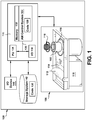
- FIG. 1 shows a block diagram of an additive manufacturing process including a non-transitory computer readable storage medium storing code representative of an article according to embodiments of the disclosure.
- the nickel alloy for use in direct metal laser melting.
- the nickel alloy can advantageously be used for welding, sintering, and laser melting.
- the nickel alloy comprises a powder, the powder including aluminum, titanium, niobium, chromium, cobalt, tungsten, carbon, boron, and nickel.
- concentrations of aluminum and titanium allow for an improved characteristics pertaining to low cycle fatigue, creep strain, oxidation resistance, and hot corrosion resistance.
- the nickel alloy may comprise about 1.6 to about 2.8 weight percent aluminum and about 2.2 to about 2.4 weight percent titanium. This chemistry provides a good compromise between high temperature strength and degree of weldability.
- the nickel alloy powder may further include the following concentrations; about 1.25 to about 2.05 weight percent niobium; about 22.2 to about 22.8 weight percent chromium; about 8.5 to about 19.5 weight percent cobalt; about 1.8 to about 2.2 weight percent tungsten; about 0.005 to about 0.1 weight percent carbon; about 0.002 to about 0.015 weight percent boron; and about 40 to about 70 weight percent nickel. More particularly, in some embodiments, the nickel alloy powder may include about 0.001 to about 0.05 weight percent carbon and in some embodiments even about 0.005 to about 0.01 weight percent carbon Carbon may combine with other elements in the nickel alloy powder to form carbides. These carbides strengthen the nickel alloy powder and create residual stresses within the nickel alloy powder.
- the nickel alloy powder includes small particles.
- the particles may be equal to or less than approximately 44 microns in size. This size parameter assists in the ability to be used for DMLM due to the heat source and ease of melting or sintering the particles of the powder.
- the particles may be more than or equal to approximately 10 microns in diameter. As should be understood, these size ranges may vary by 5 microns and particles of the powder can be synthesized within the size range, or may be filtered to a specific size using any now known or later developed technique.
- a specific size sieve may be used to filter the particles, and in some instances, a largest size sieve and a smallest size sieve may be utilized in order to create an upper limit and a lower limit to the diameter of the particles of the nickel alloy powder.
- the above disclosed nickel alloy powder is used in a method of manufacturing an article.
- the method may include providing a 3D design file of the article. Then, using a 3D printer, the above described alloy powder is applied in a repeated layered fashion and an energy source is applied to the powder.
- the powder used in the manufacturing process produces an article which has a low cycle fatigue characteristic as measured by a strain range percentage and a number of cycles to crack initiation.
- the article also has a low creep strain characteristic, a high oxidation resistance characteristic, and a high hot corrosion resistance characteristic.
- Articles according to embodiments of the present invention, due to these characteristics, are stronger than previous alloys such as, but not limited to, HastX, IN617, and IN625.
- the article of the manufacturing process can be used in a number of applications.
- the article may be used as a component of a turbine.
- the article can be used for first stage and later stage turbine nozzle applications and for use in large buckets for turbines.
- FIG. 1 shows a schematic/block view of an illustrative computerized additive manufacturing system 100 for generating an article 102.
- system 100 is arranged for DMLM.
- Article 102 is illustrated as a double walled turbine element; however, it is understood that the additive manufacturing process can be readily adapted to manufacture any article.
- AM system 100 generally includes a computerized additive manufacturing (AM) control system 104 and an AM printer 106.
- AM system 100 executes code 120 that includes a set of computer-executable instructions defining article 102 to physically generate the object using AM printer 106.
- Each AM process may use different raw materials in the form of, for example, fine-grain powder, liquid (e.g., polymers), sheet, etc., a stock of which may be held in a chamber 110 of AM printer 106, including the above disclosed nickel alloy powder.
- an applicator 112 may create a thin layer of raw material 114 spread out as the blank canvas from which each successive slice of the final object will be created.
- applicator 112 may directly apply or print the next layer onto a previous layer as defined by code 120, e.g., where the material is a polymer.
- a laser or electron beam 116 fuses particles for each slice, as defined by code 120.
- Various parts of AM printer 106 may move to accommodate the addition of each new layer, e.g., a build platform 118 may lower and/or chamber 110 and/or applicator 112 may rise after each layer.
- AM control system 104 is shown implemented on computer 130 as computer program code.
- computer 130 is shown including a memory 132, a processor 134, an input/output (I/O) interface 136, and a bus 138.
- I/O input/output
- computer 130 is shown in communication with an external I/O device/resource 140 and a storage system 142.
- processor 134 executes computer program code, such as AM control system 104, that is stored in memory 132 and/or storage system 142 under instructions from code 120 representative of article 102, described herein. While executing computer program code, processor 134 can read and/or write data to/from memory 132, storage system 142, I/O device 140 and/or AM printer 106.
- Bus 138 provides a communication link between each of the components in computer 130, and I/O device 140 can comprise any device that enables a user to interact with computer 140 (e.g., keyboard, pointing device, display, etc.).
- Computer 130 is only representative of various possible combinations of hardware and software.
- processor 134 may comprise a single processing unit, or be distributed across one or more processing units in one or more locations, e.g., on a client and server.
- memory 132 and/or storage system 142 may reside at one or more physical locations.
- Memory 132 and/or storage system 142 can comprise any combination of various types of non-transitory computer readable storage medium including magnetic media, optical media, random access memory (RAM), read only memory (ROM), etc.
- Computer 130 can comprise any type of computing device such as a network server, a desktop computer, a laptop, a handheld device, a mobile phone, a pager, a personal data assistant, etc.
- Additive manufacturing processes begin with a non-transitory computer readable storage medium (e.g., memory 132, storage system 142, etc.) storing code 120 representative of article 102.
- code 120 includes a set of computer-executable instructions defining article 102 that can be used to physically generate the object, upon execution of the code by system 100.
- code 120 may include a precisely defined 3D model of object 102 and can be generated from any of a large variety of well known computer aided design (CAD) software systems such as AutoCAD®, TurboCAD®, DesignCAD 3D Max, etc.
- CAD computer aided design
- code 120 can take any now known or later developed file format.
- code 120 may be in the Standard Tessellation Language (STL) which was created for stereolithography CAD programs of 3D Systems, or an additive manufacturing file (AMF), which is an American Society of Mechanical Engineers (ASME) standard that is an extensible markup-language (XML) based format designed to allow any CAD software to describe the shape and composition of any three-dimensional object to be fabricated on any AM printer.
- STL Standard Tessellation Language
- AMF additive manufacturing file
- ASME American Society of Mechanical Engineers
- XML extensible markup-language
- Code 120 may be translated between different formats, converted into a set of data signals and transmitted, received as a set of data signals and converted to code, stored, etc., as necessary.
- Code 120 may be an input to system 100 and may come from a part designer, an intellectual property (IP) provider, a design company, the operator or owner of system 100, or from other sources.
- IP intellectual property
- AM control system 104 executes code 120, article 102 into a series of thin slices that it assembles using AM printer 106 in successive layers of liquid, powder, sheet or other material.
- each layer is melted to the exact geometry defined by code 120 and fused to the preceding layer.
- article 102 may be exposed to any variety of finishing processes, e.g., minor machining, sealing, polishing, assembly to other part of the igniter tip, etc.
Landscapes
- Engineering & Computer Science (AREA)
- Chemical & Material Sciences (AREA)
- Materials Engineering (AREA)
- Manufacturing & Machinery (AREA)
- Physics & Mathematics (AREA)
- Plasma & Fusion (AREA)
- Mechanical Engineering (AREA)
- Optics & Photonics (AREA)
- Metallurgy (AREA)
- Organic Chemistry (AREA)
- Powder Metallurgy (AREA)
Abstract
Description
- The disclosure relates generally to materials for Direct Metal Laser Melting (DMLM) techniques.
- DMLM, also sometimes referred to as Selective Laser Melting (SLM), is an additive manufacturing technology capable of being used to build parts with complex geometries, however without requiring the tooling techniques common with non-additive manufacturing techniques. DMLM frequently uses 3D CAD data in a digital format combined with an energy source, typically a high-power laser in order to create three-dimensional metal or alloy parts by fusing together particles of metallic powders or powders of alloys. Due to this fact, the quality of the DMLM powder used will directly impact the physical properties and the quality of the resulting part.
- Previous embodiments have utilized a number of materials for DMLM. For instance, stainless steel, aluminum, maraging (or tooling) steel, titanium alloys, and cobalt chrome have previously been utilized. However, a better DMLM powder needs to be developed.
- Embodiments of the invention disclosed herein may include a nickel alloy for direct metal laser melting, the nickel alloy including: a powder including: about 1.6 to about 2.8 weight percent aluminum; about 2.2 to about 2.4 weight percent titanium; about 1.25 to about 2.05 weight percent niobium; about 22.2 to about 22.8 weight percent chromium; about 8.5 to about 19.5 weight percent cobalt; about 1.8 to about 2.2 weight percent tungsten; about 0.001 to about 0.05 weight percent carbon; about 0.002 to about 0.015 weight percent boron; and about 40 to about 70 weight percent nickel.
- Embodiments of the invention may also include a method of manufacturing an article, the method including: providing a 3D design file of the article; and using a 3D printer, applying in a repeated layered fashion according to the 3D design file, an energy source to a powder, the powder comprising: about 1.6 to about 2.8 weight percent aluminum; about 2.2 to about 2.4 weight percent titanium; about 1.25 to about 2.05 weight percent niobium; about 22.2 to about 22.8 weight percent chromium; about 8.5 to about 19.5 weight percent cobalt; about 1.8 to about 2.2 weight percent tungsten; about 0.001 to about 0.05 weight percent carbon; about 0.002 to about 0.015 weight percent boron; and about 40 to about 70 weight percent nickel.
- Embodiments of the invention may also include a direct metal laser melting system including: a powder; a build platform for holding at least a layer of the powder; and a 3D printer configured to apply an energy source to the powder in a repeated layered fashion according to a 3D design file of an article, wherein the powder comprises: about 1.6 to about 2.8 weight percent aluminum; about 2.2 to about 2.4 weight percent titanium; about 1.25 to about 2.05 weight percent niobium; about 22.2 to about 22.8 weight percent chromium; about 8.5 to about 19.5 weight percent cobalt; about 1.8 to about 2.2 weight percent tungsten; about 0.001 to about 0.05 weight percent carbon; about 0.002 to about 0.015 weight percent boron; and about 40 to about 70 weight percent nickel.
- These and other features of the disclosure will be more readily understood from the following detailed description of the various aspects of the invention taken in conjunction with the accompanying drawings that depict various aspects of the invention.
-
FIG. 1 shows a block diagram of an additive manufacturing process including a non-transitory computer readable storage medium storing code representative of an article according to embodiments of the disclosure. - It is noted that the drawings may not be to scale. The drawings are intended to depict only typical aspects of the invention, and therefore should not be considered as limiting the scope of the invention. In the drawings, like numbering represents like elements between the drawings. The detailed description explains embodiments of the invention, together with advantages and features, by way of example with reference to the drawings.
- Disclosed herein is a nickel alloy for use in direct metal laser melting. The nickel alloy can advantageously be used for welding, sintering, and laser melting. The nickel alloy comprises a powder, the powder including aluminum, titanium, niobium, chromium, cobalt, tungsten, carbon, boron, and nickel. The unique combination of concentrations of aluminum and titanium allow for an improved characteristics pertaining to low cycle fatigue, creep strain, oxidation resistance, and hot corrosion resistance.
- In some embodiments, the nickel alloy may comprise about 1.6 to about 2.8 weight percent aluminum and about 2.2 to about 2.4 weight percent titanium. This chemistry provides a good compromise between high temperature strength and degree of weldability. These and other features will become clearer in light of the descriptions below.
- In some embodiments, the nickel alloy powder may further include the following concentrations; about 1.25 to about 2.05 weight percent niobium; about 22.2 to about 22.8 weight percent chromium; about 8.5 to about 19.5 weight percent cobalt; about 1.8 to about 2.2 weight percent tungsten; about 0.005 to about 0.1 weight percent carbon; about 0.002 to about 0.015 weight percent boron; and about 40 to about 70 weight percent nickel. More particularly, in some embodiments, the nickel alloy powder may include about 0.001 to about 0.05 weight percent carbon and in some embodiments even about 0.005 to about 0.01 weight percent carbon Carbon may combine with other elements in the nickel alloy powder to form carbides. These carbides strengthen the nickel alloy powder and create residual stresses within the nickel alloy powder. During 3D printing, relaxing these stresses may be desirable. If there is a resistance to relaxing these stresses, cracks may be created within the nickel alloy powder. That is, a higher carbon content within the nickel alloy powder results in greater amount of carbides and hence a propensity for cracking. Therefore, reducing the carbon content low helps prevent cracking. During other manufacturing processes, such as investment casting, the amount of carbon is not of the same concern as in 3D printing as cracking issues during investment casting is not typically caused by a greater amount of carbon or carbides.
- In some embodiments, the nickel alloy powder includes small particles. For instance, the particles may be equal to or less than approximately 44 microns in size. This size parameter assists in the ability to be used for DMLM due to the heat source and ease of melting or sintering the particles of the powder. In a further embodiment, the particles may be more than or equal to approximately 10 microns in diameter. As should be understood, these size ranges may vary by 5 microns and particles of the powder can be synthesized within the size range, or may be filtered to a specific size using any now known or later developed technique. In some embodiments, a specific size sieve may be used to filter the particles, and in some instances, a largest size sieve and a smallest size sieve may be utilized in order to create an upper limit and a lower limit to the diameter of the particles of the nickel alloy powder.
- In further embodiments, the above disclosed nickel alloy powder is used in a method of manufacturing an article. In particular, the method may include providing a 3D design file of the article. Then, using a 3D printer, the above described alloy powder is applied in a repeated layered fashion and an energy source is applied to the powder. As discussed above, the powder used in the manufacturing process produces an article which has a low cycle fatigue characteristic as measured by a strain range percentage and a number of cycles to crack initiation. The article also has a low creep strain characteristic, a high oxidation resistance characteristic, and a high hot corrosion resistance characteristic. Articles according to embodiments of the present invention, due to these characteristics, are stronger than previous alloys such as, but not limited to, HastX, IN617, and IN625.
- The article of the manufacturing process can be used in a number of applications. For instance, the article may be used as a component of a turbine. The article can be used for first stage and later stage turbine nozzle applications and for use in large buckets for turbines.
- To illustrate an example additive manufacturing process such as DMLM,
FIG. 1 shows a schematic/block view of an illustrative computerizedadditive manufacturing system 100 for generating anarticle 102. In this example,system 100 is arranged for DMLM. It is understood that the general teachings of the disclosure are equally applicable to other forms of additive manufacturing.Article 102 is illustrated as a double walled turbine element; however, it is understood that the additive manufacturing process can be readily adapted to manufacture any article.AM system 100 generally includes a computerized additive manufacturing (AM)control system 104 and anAM printer 106.AM system 100, as will be described, executescode 120 that includes a set of computer-executableinstructions defining article 102 to physically generate the object usingAM printer 106. Each AM process may use different raw materials in the form of, for example, fine-grain powder, liquid (e.g., polymers), sheet, etc., a stock of which may be held in achamber 110 ofAM printer 106, including the above disclosed nickel alloy powder. As illustrated, anapplicator 112 may create a thin layer ofraw material 114 spread out as the blank canvas from which each successive slice of the final object will be created. In other cases,applicator 112 may directly apply or print the next layer onto a previous layer as defined bycode 120, e.g., where the material is a polymer. In the example shown, a laser orelectron beam 116 fuses particles for each slice, as defined bycode 120. Various parts ofAM printer 106 may move to accommodate the addition of each new layer, e.g., abuild platform 118 may lower and/orchamber 110 and/orapplicator 112 may rise after each layer. -
AM control system 104 is shown implemented oncomputer 130 as computer program code. To this extent,computer 130 is shown including amemory 132, aprocessor 134, an input/output (I/O)interface 136, and abus 138. Further,computer 130 is shown in communication with an external I/O device/resource 140 and astorage system 142. In general,processor 134 executes computer program code, such asAM control system 104, that is stored inmemory 132 and/orstorage system 142 under instructions fromcode 120 representative ofarticle 102, described herein. While executing computer program code,processor 134 can read and/or write data to/frommemory 132,storage system 142, I/O device 140 and/orAM printer 106.Bus 138 provides a communication link between each of the components incomputer 130, and I/O device 140 can comprise any device that enables a user to interact with computer 140 (e.g., keyboard, pointing device, display, etc.).Computer 130 is only representative of various possible combinations of hardware and software. For example,processor 134 may comprise a single processing unit, or be distributed across one or more processing units in one or more locations, e.g., on a client and server. Similarly,memory 132 and/orstorage system 142 may reside at one or more physical locations.Memory 132 and/orstorage system 142 can comprise any combination of various types of non-transitory computer readable storage medium including magnetic media, optical media, random access memory (RAM), read only memory (ROM), etc.Computer 130 can comprise any type of computing device such as a network server, a desktop computer, a laptop, a handheld device, a mobile phone, a pager, a personal data assistant, etc. - Additive manufacturing processes begin with a non-transitory computer readable storage medium (e.g.,
memory 132,storage system 142, etc.) storingcode 120 representative ofarticle 102. As noted,code 120 includes a set of computer-executableinstructions defining article 102 that can be used to physically generate the object, upon execution of the code bysystem 100. For example,code 120 may include a precisely defined 3D model ofobject 102 and can be generated from any of a large variety of well known computer aided design (CAD) software systems such as AutoCAD®, TurboCAD®, DesignCAD 3D Max, etc. In this regard,code 120 can take any now known or later developed file format. For example,code 120 may be in the Standard Tessellation Language (STL) which was created for stereolithography CAD programs of 3D Systems, or an additive manufacturing file (AMF), which is an American Society of Mechanical Engineers (ASME) standard that is an extensible markup-language (XML) based format designed to allow any CAD software to describe the shape and composition of any three-dimensional object to be fabricated on any AM printer.Code 120 may be translated between different formats, converted into a set of data signals and transmitted, received as a set of data signals and converted to code, stored, etc., as necessary.Code 120 may be an input tosystem 100 and may come from a part designer, an intellectual property (IP) provider, a design company, the operator or owner ofsystem 100, or from other sources. In any event,AM control system 104 executescode 120,article 102 into a series of thin slices that it assembles usingAM printer 106 in successive layers of liquid, powder, sheet or other material. In the DMLM example, each layer is melted to the exact geometry defined bycode 120 and fused to the preceding layer. Subsequently,article 102 may be exposed to any variety of finishing processes, e.g., minor machining, sealing, polishing, assembly to other part of the igniter tip, etc. - The terminology used herein is for the purpose of describing particular embodiments only and is not intended to be limiting of the disclosure. As used herein, the singular forms "a", "an" and "the" are intended to include the plural forms as well, unless the context clearly indicates otherwise. It will be further understood that the terms "comprises" and/or "comprising," when used in this specification, specify the presence of stated features, integers, steps, operations, elements, and/or components, but do not preclude the presence or addition of one or more other features, integers, steps, operations, elements, components, and/or groups thereof.
- While the invention has been described in detail in connection with only a limited number of embodiments, it should be readily understood that the invention is not limited to such disclosed embodiments. Rather, the invention can be modified to incorporate any number of variations, alterations, substitutions or equivalent arrangements not heretofore described, but which are commensurate with the spirit and scope of the invention. Additionally, while various embodiments of the invention have been described, it is to be understood that aspects of the invention may include only some of the described embodiments. Accordingly, the invention is not to be seen as limited by the foregoing description, but is only limited by the scope of the appended claims.
Claims (12)
- A nickel alloy for direct metal laser melting, the nickel alloy comprising:a powder including:1.6 to 2.8 weight percent aluminum;2.2 to 2.4 weight percent titanium;1.25 to 2.05 weight percent niobium;22.2 to 22.8 weight percent chromium;8.5 to 19.5 weight percent cobalt;1.8 to 2.2 weight percent tungsten;0.001 to 0.05 weight percent carbon;0.002 to 0.015 weight percent boron; and40 to 70 weight percent nickel.
- The nickel alloy of claim 1, wherein the powder comprises particles of less than or equal to 44 microns in size.
- The nickel alloy of claim 1 or 2, wherein the powder comprises particles of more than or equal to 10 microns in size.
- A method of manufacturing an article (102), the method comprising:providing a 3D design file of the article (102); andusing a 3D printer (106), applying in a repeated layered fashion according to the 3D design file, an energy source to a powder, the powder comprising:1.6 to 2.8 weight percent aluminum;2.2 to 2.4 weight percent titanium;1.25 to 2.05 weight percent niobium;22.2 to 22.8 weight percent chromium;8.5 to 19.5 weight percent cobalt;1.8 to 2.2 weight percent tungsten;0.001 to 0.05 weight percent carbon;0.002 to 0.015 weight percent boron; and40 to 70 weight percent nickel.
- The method of claim 4, wherein the powder comprises particles of less than or equal to 44 microns in size.
- The method of claim 4 or 5, wherein the powder comprises particles of more than or equal to 10 microns in size.
- The method of any one of claims 4 to 6, wherein the using includes welding, sintering, or laser melting.
- The method of any one of claims 4 to 7, wherein the article (102) comprises a turbine component.
- A direct metal laser melting system comprising:a build platform (118) for holding at least a layer of a powder; anda 3D printer (106) configured to apply an energy source to the powder in a repeated layered fashion according to a 3D design file of an article (102), wherein the powder comprises:1.6 to 2.8 weight percent aluminum;2.2 to 2.4 weight percent titanium;1.25 to 2.05 weight percent niobium;22.2 to 22.8 weight percent chromium;8.5 to 19.5 weight percent cobalt;1.8 to 2.2 weight percent tungsten;0.001 to 0.05 weight percent carbon;0.002 to 0.015 weight percent boron; and40 to 70 weight percent nickel.
- The direct metal laser melting system of claim 9, wherein the powder comprises particles of less than or equal to 44 microns in size.
- The direct metal laser melting system of claim 9 or 10, wherein the powder comprises particles of more than or equal to 10 microns in size.
- The direct metal laser melting system of any one of claims 9 to 11, wherein the article (102) comprises a turbine component.
Applications Claiming Priority (1)
| Application Number | Priority Date | Filing Date | Title |
|---|---|---|---|
| US15/375,380 US20170088918A1 (en) | 2014-09-19 | 2016-12-12 | Materials for direct metal laser melting |
Publications (1)
| Publication Number | Publication Date |
|---|---|
| EP3332892A1 true EP3332892A1 (en) | 2018-06-13 |
Family
ID=60629440
Family Applications (1)
| Application Number | Title | Priority Date | Filing Date |
|---|---|---|---|
| EP17204980.1A Withdrawn EP3332892A1 (en) | 2016-12-12 | 2017-12-01 | Materials for direct metal laser melting |
Country Status (2)
| Country | Link |
|---|---|
| EP (1) | EP3332892A1 (en) |
| JP (1) | JP2018150615A (en) |
Cited By (1)
| Publication number | Priority date | Publication date | Assignee | Title |
|---|---|---|---|---|
| US11458537B2 (en) | 2017-03-29 | 2022-10-04 | Mitsubishi Heavy Industries, Ltd. | Heat treatment method for additive manufactured Ni-base alloy object, method for manufacturing additive manufactured Ni-base alloy object, Ni-base alloy powder for additive manufactured object, and additive manufactured Ni-base alloy object |
Citations (3)
| Publication number | Priority date | Publication date | Assignee | Title |
|---|---|---|---|---|
| EP0876513A1 (en) * | 1995-12-21 | 1998-11-11 | Teledyne Industries, Inc | Stress rupture properties of nickel-chromium-cobalt alloys by adjustment of the levels of phosphorus and boron |
| EP2902516A1 (en) * | 2014-01-31 | 2015-08-05 | General Electric Company | A weld filler for nickel-base superalloys |
| US20160082511A1 (en) * | 2014-09-19 | 2016-03-24 | General Electric Company | Materials for direct metal laser melting |
Family Cites Families (2)
| Publication number | Priority date | Publication date | Assignee | Title |
|---|---|---|---|---|
| US20140205490A1 (en) * | 2012-07-31 | 2014-07-24 | General Electric Company | Nickel-based alloy and turbine component having nickel-based alloy |
| JP6432822B2 (en) * | 2014-07-25 | 2018-12-05 | 日立金属株式会社 | Alloy powder used for melt lamination molding |
-
2017
- 2017-11-29 JP JP2017228508A patent/JP2018150615A/en active Pending
- 2017-12-01 EP EP17204980.1A patent/EP3332892A1/en not_active Withdrawn
Patent Citations (3)
| Publication number | Priority date | Publication date | Assignee | Title |
|---|---|---|---|---|
| EP0876513A1 (en) * | 1995-12-21 | 1998-11-11 | Teledyne Industries, Inc | Stress rupture properties of nickel-chromium-cobalt alloys by adjustment of the levels of phosphorus and boron |
| EP2902516A1 (en) * | 2014-01-31 | 2015-08-05 | General Electric Company | A weld filler for nickel-base superalloys |
| US20160082511A1 (en) * | 2014-09-19 | 2016-03-24 | General Electric Company | Materials for direct metal laser melting |
Cited By (1)
| Publication number | Priority date | Publication date | Assignee | Title |
|---|---|---|---|---|
| US11458537B2 (en) | 2017-03-29 | 2022-10-04 | Mitsubishi Heavy Industries, Ltd. | Heat treatment method for additive manufactured Ni-base alloy object, method for manufacturing additive manufactured Ni-base alloy object, Ni-base alloy powder for additive manufactured object, and additive manufactured Ni-base alloy object |
Also Published As
| Publication number | Publication date |
|---|---|
| JP2018150615A (en) | 2018-09-27 |
Similar Documents
| Publication | Publication Date | Title |
|---|---|---|
| US20160082511A1 (en) | Materials for direct metal laser melting | |
| Tepylo et al. | Laser‐based additive manufacturing technologies for aerospace applications | |
| Gradl et al. | Robust metal additive manufacturing process selection and development for aerospace components | |
| Srivastava et al. | A review on recent progress in solid state friction based metal additive manufacturing: friction stir additive techniques | |
| Dutta et al. | The additive manufacturing (AM) of titanium alloys | |
| Frazier | Metal additive manufacturing: a review | |
| Korpela et al. | Additive manufacturing—Past, present, and the future | |
| EP2886225B1 (en) | Gamma prime precipitation strengthened nickel-base superalloy for use in powder based additive manufacturing process | |
| JP7250437B2 (en) | Composite components with angled braze joints, coupon brazing methods and related storage media | |
| Zhang et al. | Metal additive manufacturing in aircraft: Current application, opportunities and challenges | |
| Harris | Development and implementation of metals additive manufacturing | |
| Nickels | Additive manufacturing: A user's guide | |
| Dordlofva et al. | Opportunities and challenges for additive manufacturing in space applications | |
| US20180002785A1 (en) | Article and additive manufacturing method for making | |
| Singh et al. | Metal additive manufacturing: from history to applications | |
| US20170088918A1 (en) | Materials for direct metal laser melting | |
| Andreacola et al. | 3D-printed metals: Process parameters effects on mechanical properties of 17-4 P H stainless steel | |
| Capasso et al. | Additive manufacturing of metal materials for construction engineering: An overview on technologies and applications | |
| EP3530378A1 (en) | Methods for additively manufacturing turbine engine components via binder jet printing with titanium aluminide alloys | |
| EP3530380A1 (en) | Methods for additively manufacturing turbine engine components via binder jet printing with gamma prime precipitation hardened nickel-based superalloys | |
| Silva et al. | Introduction and main principles in additive manufacturing | |
| Wang et al. | Improving component dimensional accuracy in electron beam powder bed fusion by addressing nonlinear deformations with 3D compensation strategies | |
| EP3332892A1 (en) | Materials for direct metal laser melting | |
| EP3524374A1 (en) | Methods for additively manufacturing turbine engine components via binder jet printing with nickel-chromium-tungsten-molybdenum alloys | |
| dos Santos | Cost estimation model for the directed energy deposition process adopting an activity-based approach |
Legal Events
| Date | Code | Title | Description |
|---|---|---|---|
| PUAI | Public reference made under article 153(3) epc to a published international application that has entered the european phase |
Free format text: ORIGINAL CODE: 0009012 |
|
| STAA | Information on the status of an ep patent application or granted ep patent |
Free format text: STATUS: THE APPLICATION HAS BEEN PUBLISHED |
|
| AK | Designated contracting states |
Kind code of ref document: A1 Designated state(s): AL AT BE BG CH CY CZ DE DK EE ES FI FR GB GR HR HU IE IS IT LI LT LU LV MC MK MT NL NO PL PT RO RS SE SI SK SM TR |
|
| AX | Request for extension of the european patent |
Extension state: BA ME |
|
| STAA | Information on the status of an ep patent application or granted ep patent |
Free format text: STATUS: REQUEST FOR EXAMINATION WAS MADE |
|
| 17P | Request for examination filed |
Effective date: 20181213 |
|
| RBV | Designated contracting states (corrected) |
Designated state(s): AL AT BE BG CH CY CZ DE DK EE ES FI FR GB GR HR HU IE IS IT LI LT LU LV MC MK MT NL NO PL PT RO RS SE SI SK SM TR |
|
| STAA | Information on the status of an ep patent application or granted ep patent |
Free format text: STATUS: EXAMINATION IS IN PROGRESS |
|
| 17Q | First examination report despatched |
Effective date: 20200127 |
|
| STAA | Information on the status of an ep patent application or granted ep patent |
Free format text: STATUS: THE APPLICATION IS DEEMED TO BE WITHDRAWN |
|
| 18D | Application deemed to be withdrawn |
Effective date: 20200609 |