EP3332840A1 - Harness - Google Patents
Harness Download PDFInfo
- Publication number
- EP3332840A1 EP3332840A1 EP17205383.7A EP17205383A EP3332840A1 EP 3332840 A1 EP3332840 A1 EP 3332840A1 EP 17205383 A EP17205383 A EP 17205383A EP 3332840 A1 EP3332840 A1 EP 3332840A1
- Authority
- EP
- European Patent Office
- Prior art keywords
- bearing member
- flexible load
- load
- harness
- harness according
- Prior art date
- Legal status (The legal status is an assumption and is not a legal conclusion. Google has not performed a legal analysis and makes no representation as to the accuracy of the status listed.)
- Granted
Links
Images





Classifications
-
- A—HUMAN NECESSITIES
- A62—LIFE-SAVING; FIRE-FIGHTING
- A62B—DEVICES, APPARATUS OR METHODS FOR LIFE-SAVING
- A62B35/00—Safety belts or body harnesses; Similar equipment for limiting displacement of the human body, especially in case of sudden changes of motion
- A62B35/0006—Harnesses; Accessories therefor
-
- A—HUMAN NECESSITIES
- A62—LIFE-SAVING; FIRE-FIGHTING
- A62B—DEVICES, APPARATUS OR METHODS FOR LIFE-SAVING
- A62B35/00—Safety belts or body harnesses; Similar equipment for limiting displacement of the human body, especially in case of sudden changes of motion
- A62B35/0006—Harnesses; Accessories therefor
- A62B35/0012—Sit harnesses
-
- A—HUMAN NECESSITIES
- A62—LIFE-SAVING; FIRE-FIGHTING
- A62B—DEVICES, APPARATUS OR METHODS FOR LIFE-SAVING
- A62B35/00—Safety belts or body harnesses; Similar equipment for limiting displacement of the human body, especially in case of sudden changes of motion
- A62B35/0006—Harnesses; Accessories therefor
- A62B35/0025—Details and accessories
- A62B35/0031—Belt sorting accessories, e.g. devices keeping the belts in comfortable positions
-
- A—HUMAN NECESSITIES
- A62—LIFE-SAVING; FIRE-FIGHTING
- A62B—DEVICES, APPARATUS OR METHODS FOR LIFE-SAVING
- A62B35/00—Safety belts or body harnesses; Similar equipment for limiting displacement of the human body, especially in case of sudden changes of motion
- A62B35/0006—Harnesses; Accessories therefor
- A62B35/0025—Details and accessories
- A62B35/0037—Attachments for lifelines and lanyards
-
- A—HUMAN NECESSITIES
- A62—LIFE-SAVING; FIRE-FIGHTING
- A62B—DEVICES, APPARATUS OR METHODS FOR LIFE-SAVING
- A62B35/00—Safety belts or body harnesses; Similar equipment for limiting displacement of the human body, especially in case of sudden changes of motion
- A62B35/04—Safety belts or body harnesses; Similar equipment for limiting displacement of the human body, especially in case of sudden changes of motion incorporating energy absorbing means
Definitions
- This invention relates to personal protective equipment and, more particularly, harnesses or components thereof. Particularly, but not exclusively, the invention relates to components used to make a harness suitable for use in supporting a person working at height using rope access and hardware (metal components) that are used within its construction. It also has application for a harness and hardware that are part of a fall-protection system, for example for use by a climber.
- a harness may be designed to support a user when working at height, to provide a comfortable body support for performing tasks when suspended from a rope access system.
- a harness may be used to arrest a user's fall, for example in a fall protection system used by a climber where there is the potential for a fall.
- Embodiments of the invention might find application to hardware used for rope access, industrial height safety, rescue, tactical applications, sport climbing, etc.
- example embodiments will be described that relate to harnesses intended for use in tree care, but this should not be taken to be limiting upon the range of applications of the invention.
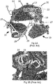
- This application relates to the components of a harness assembly which is of the general construction shown in Figures 1A, 1B and 2 .
- FIG. 1A A known harness is shown in Figure 1A .
- the harness comprises two leg loops 10 that, in use, encircle a user's thighs.
- Each leg loop 10 is connected to a padded back 12 that rests against the small of a user's back and has side wings that extend to above a user's hips when in use.
- the back has a waist webbing 14 that has ends that can be interconnected by a releasable front waist buckle 16.
- Each side wing has a side attachment arrangement 20, shown in more detail in Figure 1B .
- Each side attachment arrangement 20 connects the waist webbing 14 in the region of the wing through a riser webbing 18 to the corresponding leg loop 10.
- the side attachment arrangement 20 comprises two metal loops 22, 24 through which the waist webbing 14 passes.
- Typical known forward attachment arrangements include a connector 27 shown in Figure 2 that is sewn in to the riser 18 and leg loop 10 webbing.
- the flexible load-bearing member 28 is tied in to the connector 27 during manufacture of the harness.
- the flexible load bearing member 28 can be adjusted in length by repositioning a knot on the one end by the user which is time consuming and potentially hazardous for the user if done incorrectly.
- An aim of this invention is to provide a harness that that overcomes or at least ameliorates these disadvantages.
- the present invention provides a harness for supporting a person working at height comprising some or all of a back, leg loops, two forward connection arrangements and a flexible load-bearing member that extends between the connection arrangements, the forward connection arrangements serving to transferring load from the back and the leg loops to the load-bearing member,
- one or each forward connection arrangement comprises: a body that is permanently connected to the harness and a retention component that can be removably and typically rigidly connected to the body to removably secure the flexible load-bearing member to the body, and thence to the other components of the harness.
- Replacement of the flexible load-bearing member can be achieved by removal of the retention components during servicing of the harness.
- Suitable formations for connection to the retention components such as sewn loops, can be provided in the flexible load-bearing member during its manufacture, thereby avoiding the need to form them later, as is the case of a conventional flexible load-bearing member, which has to be securely knotted after it has been installed in the forward connection arrangement.
- the flexible load-bearing member may include a loop and the retention components include a bar that when separate from the body can pass through the loop, and that, when connected to the body, is secured within the loop.
- the bar is typically secured to the body by bolts and nuts.
- the loop may be formed to include a region which will fail upon application of a force above a threshold but below a maximum working force to cause the effective length of the flexible load-bearing member to increase. This can limit the force that is applied to a user when the harness is acting to arrest a fall.
- the retention component may include a knot blocker. That is, a component with a through hole through which a length of rope can pass, but which prevents the passage of a knotted rope. This can provide a more versatile form of attachment, allowing a user to adjust the length of the bridge by varying the position of a knot upon it.
- the retention components include an adjuster (e.g., a rope adjuster) that can be caused to grip the flexible load-bearing member at one of a range of positions.
- the adjuster allows the effective length of the flexible load-bearing member to decrease by application of a tensile force to a free end of the flexible load-bearing member.
- the adjuster may allow the effective length of the flexible load-bearing member to increase upon manual intervention by a user prior to application of a tensile force to the flexible load-bearing member.
- the secured flexible connecting member passes through the body. This can ensure that the connection between the flexible load-bearing member and the body is not immediately lost in the event that the retention components become detached from the body, for example, as a result of a fastener becoming loose.
- a harness embodying the invention may have two similar forward connection arrangements. Alternatively, it may have two dissimilar forward connection arrangements, for example, one having a loop and retention bar arrangement and the other having a rope adjuster arrangement as discussed above.
- a harness embodying the invention may have one, two or more flexible connecting members each of which is removably secured to the harness by the or each forward connection arrangement.
- the body of each forward connection arrangement is permanently connected to a waist webbing that extends about the back of the harness and the body of each forward connection arrangement is permanently connected to a respective riser that is connected to a respective leg loop.
- the present invention provides a harness for supporting a person working at height comprising some or all of a back, leg loops, two forward connection arrangements and a flexible load-bearing member that extends between the connection arrangements, the forward connection arrangements serving to transferring load from the back and the leg loops to the load-bearing member, in which flexible load-bearing member includes an energy dissipation region which will fail upon application of a force above a threshold but below a maximum working force to cause the effective length of the flexible load-bearing member to increase.
- the energy dissipation region may include a region that will fail progressively upon the load in the flexible load-bearing member being in excess of the threshold.
- the energy dissipation region may include stitching that will progressively fail when the load in the flexible load-bearing member being in excess of the threshold.
- the load-bearing member may include a load fuse which operates to transfer load between the flexible load-bearing member and the forward connection arrangement when the harness is in normal use and to fail when load in the flexible load-bearing member exceeds a threshold. Failure of the load fuse typically cause the transfer of load in the flexible load-bearing member to the energy dissipation region.
- the load fuse may comprise stitches that interconnect parts of the flexible load-bearing member.
- a harness embodying the invention has a forward attachment arrangement that includes a forward attachment assembly, as shown in Figures 3 to 10 .
- the forward attachment assembly comprises a body 30 and an attachment bar 32.
- the body 30 has a generally oval or slight figure-of-8 peripheral shape and is formed from a single piece of metal by a combination of one or more of casting, forging and machining.
- the body 30 extends in a plane P, having inner and outer surfaces disposed to opposite sides of the plane, and its periphery can be considered as defining a region of the plane through which, six holes pass.
- the body is symmetrical about an axis A that extends within the plane and that forms a long axis of the body 30.
- a bridge hole 40 is centred on the axis A approximately one third of the distance along the axis A from a first end of the axis A.
- the bridge hole 40 has shape that is square with rounded corners and has a dimension approximately one third of the width of the body 30 in the plane P transverse of the axis A.
- a first and a second webbing slot 42, 44 are disposed to opposite sides of the axis A.
- Each slot 42, 44 extends from a small distance from the axis A that lies between the bridge hole 40 and a first axial end of the body 30, each slot 42, 44 being centred along an arc that is a constant distance from a proximal part of the periphery of the body 30.
- attachment hole 46 that extends symmetrically about the axis A to partially surround the bridge hole 40 and to extend to a second axial end of the body 30. This imparts the body 30 with a D-shaped attachment portion extending from the bridge hole 40 in a direction away from the webbing slots 42, 44.
- All four above-described holes 40, 42, 44, 46 are formed with curved peripheries and without sharp corners to avoid the creation of stress risers within the body and within any object that is passed through the hole.
- Two bolt holes 48 of circular cross-section pass through the body, at an axial position that is approximately half way along the axial extent of the bridge hole.
- Each bolt hole has one end portion, opening to the inner surface do the body 30, that is countersunk.
- the attachment bar 32 has a central portion 50 of round cross-section and two securing portions 52. Each securing portion 52 has a flat mating surface. A bore extends through the securing portion 52 and opens perpendicular to the mating surface. At its opposite end, the bore has a hexagonal counterbore 56.
- a self-locking nut 58 is inserted into the hexagonal counterbore 56 of each bore in the attachment bar 32.
- a shaft of a respective cap screw 60 is inserted through each bolt hole 48 in the body from the countersunk end into a respective bore in the attachment bar 32 and then screwed into the nuts 58 in the attachment bar 32 and tightened such that the mating surfaces of the securing portions are clamped against the outer surface of the body 30.
- the above described attachment arrangement can be incorporated into a harness described in Figures 1A and 1B as a replacement for the connector 27 ( Figure 2 ).
- the body 30 is permanently installed in the harness by a leg riser webbing and a leg loop webbing passing through the webbing slots 42, 44.
- the flexible load-bearing member 28 is terminated at each end by a loop 66 that is permanently formed, for example by sewing.
- each loop 66 is passed through the bridge hole 40 of the body 30 of one of the forward attachment arrangements, as shown in Figure 7 .
- the attachment bar 32 is then passed into the loop 66 such that it projects by approximately equal distances from both sides of the loop 66.
- the forward attachment assemblies are then assembled as described in the last-preceding paragraph. This creates a secure connection between the flexible load-bearing member 28 and the forward connection arrangement, as shown in Figure 8 .
- the attachment hole 46 defines a loop within the body to which a connector, such as a carabiner, can be connected. This can be used to attach anchors that will help a user to maintain a desired position, or as a point from which items can be carried.
- a connector such as a carabiner
- the attachment bar 32 can be considered to be attached to the body 30 semi-permanently, in that it will not be removed during normal use of the harness. However, the connection is made in such a way that the flexible load-bearing member 28 can be removed and replaced as necessary, as part of a service operation, without the requirement that the user of the harness performs potentially risky procedures such as the formation of secure knots in the flexible load-bearing member 28.
- the flexible load-bearing members 28 shown above are formed of rope. However, they may have other configurations, such as being made of webbing, as shown in Figure 9 .
- one forward attachment arrangement is provided with means to adjust the length of the flexible load-bearing member 28.
- the flexible load bearing member 28 has at least one loop that is constructed in such a way as to limit the force that it can apply to the forward attachment arrangement during normal use to provide shock absorbance in the event that the harness acts to arrest a fall.
- attachment bar 32 is held within a double portion of webbing which is sewn together with a holding stitch and a further set of rippable stiches which once loaded by the bar, break sequentially to allow the bar to move through the webbing, effectively extending the length of the flexible load-bearing member 28 until an end-point is reached, with the result that the fall is arrested over a greater distance that would be the case where the loop is simply sewn at the end portion of the flexible load-bearing member 28.
- an extended loop 70 is formed at an end of the flexible load-bearing member 28, which in this case is formed from webbing (although a similar arrangement could be formed from rope).
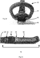
- the loop 70 is formed by folding an end portion of the webbing back on itself, and retaining it with a first, secure set of retaining stitches 72 that are close to the end of the loop nearest the centre of the flexible load-bearing member 28.
- the retaining stitches 72 are formed for maximum strength - that is, they should fail only when the absolute load limit of the flexible load-bearing member 28 has been exceeded.
- an unstitched region 74 which has an outer boundary formed by a set of holding stitches 76.
- Outwardly from the holding stitches 76 is a length of rippable stitches 78 that extends to close to the end of the flexible load-bearing member 28.
- the flexible load-bearing member 28 is installed onto the forward connection arrangement by passing the attachment bar 32 between lengths of the webbing at the unstitched region 74.
- the attachment bar 32 is inserted into the unstitched region 74 to be held between the retaining stitches 72 and the holding stitches 76, and the holding stitches will bear the normal working load transferred from the harness through the flexible load-bearing member 28.
- the holding stitches 76 are configured such that they will fail in the event that the load applied to them by the attachment bar 32 exceeds a threshold that will be encountered during normal use of the harness, such as may arise during arrest of a fall, and as such may be described as a "load fuse".
- the length of webbing in which the rippable stitches 78 is formed is folded over upon itself several times.
- the purpose of this modification is to reduce the length of the flexible load-bearing member 28 that projects beyond the forward attachment arrangement.
- the folds can be maintained by light stitching or by a removable retaining member, for example, formed of flexible elastic material.
- the load limiting arrangement of Figures 11 to 13 may be provided at both ends of the flexible load-bearing member or a just one end.
- a rope adjuster assembly 132 is secured to the body 30 by cap screws 160.
- the rope adjuster assembly 132 comprises two blocks mirror-image 134, 134', each one being secured through a bolt hole 48 the body 30 by a respective cap screw 160 positioned symmetrically to opposite sides of the bridge hole 40.
- a carrier bolt 136 extends through a bore in one block 134' and is fixed by being threaded into a tapped bore in the other block 134.
- a cylindrical boss 138 is carried on the carrier bolt 136 between the blocks 134, 134', the boss 138 being fixed against rotation about the carrier bolt 136.
- the shape of the boss may be adapted in accordance with the item that it is intended to interact with (a rope, webbing, etc.,) to ensure that the grip that it applies is optimised.
- the surface that faces the cam might be concave, v-shaped or may otherwise diverge from the straight-sided shape shown.
- a cam axle 142 extends between the blocks 134, 134', and on it a cam 144 is carried such that the cam 144 can rotate on the axle 142.
- the cam 144 has a gripping surface 146 that faces generally towards the boss138, the gripping surface being at a radial distance from the cam axle 142 that increases as the rotational distance of the gripping surface 146 from the boss 138 increases.
- the gripping surface extends onto a projecting lobe 148 of the cam 144. Gripping formations, such as transverse ridges or grooves, are formed on the gripping surface 146 to increase the friction that will occur between the gripping surface and an object sliding over it.
- a flexible load-bearing member 28 is passed through the bridge hole 40 and then placed between the blocks 134, 134'.
- the boss 138 and the carrier bolt 136 are then fitted, so trapping the flexible load-bearing member 28 between the boss 138 and the cam 144, with the flexible load-bearing member 28 being in contact with the gripping surface 146.
- the rope adjuster assembly 132 is then bolted to the body 30, which is the same as is the case in the other embodiments described herein.
- the cam 144 and the flexible load-bearing member 28 are shaped and dimensioned such that when the cam 144 is rotated away from the body, such that the distance between the gripping surface 146 and the boss 138 is at its greatest, the flexible load-bearing member 28 is gripped, such that linear movement of the flexible load-bearing member 28 through the rope adjuster assembly 132 will urge the cam to rotate. Pulling the flexible load-bearing member 28 through the rope adjuster assembly away from the body 30 urges the cam to turn to a position that maximises the distance between the gripping surface 146 and the boss 138. In this position, the flexible load-bearing member 28 can pass through the rope adjuster assembly 132 with some resistance.
- the flexible load-bearing member 28 is pulled in the opposite direction, this urges the cam 144 to rotate in a direction that would reduce the distance between the gripping surface 146 and the boss 138. If a user intervenes to prevent this rotation by applying force to the cam lobe 148, the flexible load-bearing member 28 can move linearly with some resistance. However, if the user does not intervene, the cam 144 will rotate so lessening the distance between the gripping surface 146 and the boss 138. This has the effect of clamping the flexible load-bearing member 28 between the cam 144 and the boss 138, thereby preventing further linear movement of the flexible load-bearing member 28. This allows the user to lengthen or shorten the flexible load-bearing member 28 as required.
- An end part of the load bearing member 28 has a formation that prevents it from being fully withdrawn from the rope adjuster assembly 132 (for example, a loop 66 as described above or any other formation that increases its diameter sufficiently to prevent it passing between the cam 144 and the boss 138). This prevents the load bearing member 28 from becoming disconnected inadvertently as it is being lengthened by a user.
- a flexible load-bearing member 28 formed from webbing can be used instead of one formed from rope.
- two cams 144, 144' are carried on the cam axle 142 and two bosses 138, 138' are carried on the carrier bolt 136.
- a spacer plate 170 extends between adjacent cams 144, 144' and bosses 138, 138'. This allows use and independent adjustment of two flexible load-bearing members 28.
- Figures 19 and 20 show a modification to the embodiment of Figures 3 to 6 , although it should be understood that it can be applied to other embodiments described above.
- This embodiment includes a body 230 that is broadly similar to that described above, with modifications as will now be described.
- the body 230 in this embodiment is curved, such that the attachment portion extends at a small angle (approximately 15° in this example).
- each bolt hole 248 in the outer surface is surrounded by a ridge 254.
- each bolt hole 248 is counterbored and is formed with a hexagonal cross-section 262 inwardly of the counterbore.
- This embodiment further includes an attachment bar 232 that is broadly similar to that described above, with modifications as will now be described.
- Each securing portion 252 is formed with a recess 264 that surrounds the bore where it emerges from the mating surface.
- the opposite end portion of the bore is countersunk at 256.
- a self-locking nut 258 is inserted into the hexagonal counterbore 262 of each bolt hole 248.
- a shaft of a respective cap screw 260 is inserted through the bore of each securing portion 252 of the attachment bar 232.
- the attachment bar 232 is placed on the outer surface of the body 230 such that each ridge 254 is received in a corresponding one of the recesses 264.
- the shafts of the screws 260 are passed through the bolt holes 248 in the body 230 to come into threaded engagement with the nuts 258.
- the bolts are tightened such that the mating surfaces of the securing portions 252 are clamped against the outer surface of the body 230.
- the presence of the ridges 254 and recesses 264 serve to locate the attachment bar 232 in the correct position on the body 230 and also prevents the attachment bar 232 being installed in the incorrect orientation.
- the length and diameter of the head of the screws 260 is selected such that if an attempt is made to fit the attachment bar 232 to the wrong surface of the body 230, the head will not enter the counterbores 262 of the bolt holes 248, and are not long enough to project from the attachment bar 232 so preventing the nuts 258 from being installed.
- the body 230 is the same as that in the embodiment of Figures 19 and 20 , and similar nuts and screws 260 are also included.
- the retention component of this embodiment is a knot blocking plate 280, shown in Figures 22 and 23 .
- the knot blocking plate 280 has a periphery of size and shape such that when it is placed on the body 230 it completely covers the bridge hole 240.
- An inner surface of the knot blocking plate 280 has a projecting boss 282 surrounded by a flat mating surface.
- the boss 282 is a close fit within the bridge hole such that when the knot blocking plate 280 is placed onto the body 230, the mating surface comes into contact with the outer surface of the body 230 and the boss 282 enters the bridge hole 240 to locate the knot blocking plate 280 in the correct position on the body 230.
- Two bolt holes 248 pass through the knot blocking plate 280.
- An end portion of each bolt hole 248 adjacent to the outer surface is countersunk at 286.
- a recess 288 surrounds each bolt hole 248 where it opens to the inner surface of the knot blocking plate 280.
- the presence of the ridges 254 and recesses 288 serve to locate the knot blocking plate 280 in the correct position on the body 230 and also prevents the knot blocking plate 280 being installed in the incorrect orientation.
- the length and diameter of the head of the screws 260 is selected such that if an attempt is made to fit the knot blocking plate 280 to the wrong surface of the body 230, the head will not enter the counterbores 262 of the bolt holes 248, and are not long enough to project from the attachment bar 232 so preventing the nuts 258 from being installed.
- the knot blocking plate 280 has a central rope aperture 288 that extends between the inner and outer surfaces.
- the rope aperture 288 is shaped as a rounded rectangle and dimensioned such that two lengths of rope that will be used to form the bridge can pass through it side-by-side with little space between the ropes and the material surrounding the rope aperture 288. Adjacent to where it opens to the inner and outer surfaces of the knot blocking plate 280, the rope aperture 288 is flared in order that it presents no sharp or small-radius edges to a rope passing through it.
- the rope bridge on a harness that uses the forward connection arrangement shown in Figures 21 to 23 is formed by passing two ropes through the rope aperture 288 of each knot blocking plate 280 and tying suitable stopper knots in the ropes to the outside of the knot blocking plates 280, as shown in Figure 24 .
Landscapes
- Health & Medical Sciences (AREA)
- General Health & Medical Sciences (AREA)
- Business, Economics & Management (AREA)
- Emergency Management (AREA)
- Emergency Lowering Means (AREA)
- Installation Of Indoor Wiring (AREA)
- Automotive Seat Belt Assembly (AREA)
Abstract
Description
- This invention relates to personal protective equipment and, more particularly, harnesses or components thereof. Particularly, but not exclusively, the invention relates to components used to make a harness suitable for use in supporting a person working at height using rope access and hardware (metal components) that are used within its construction. It also has application for a harness and hardware that are part of a fall-protection system, for example for use by a climber.
- A harness may be designed to support a user when working at height, to provide a comfortable body support for performing tasks when suspended from a rope access system. Alternatively or additionally, a harness may be used to arrest a user's fall, for example in a fall protection system used by a climber where there is the potential for a fall. Embodiments of the invention might find application to hardware used for rope access, industrial height safety, rescue, tactical applications, sport climbing, etc. Within this specification, example embodiments will be described that relate to harnesses intended for use in tree care, but this should not be taken to be limiting upon the range of applications of the invention.
- This application relates to the components of a harness assembly which is of the general construction shown in
Figures 1A, 1B and2 . - A known harness is shown in
Figure 1A . The harness comprises twoleg loops 10 that, in use, encircle a user's thighs. Eachleg loop 10 is connected to a paddedback 12 that rests against the small of a user's back and has side wings that extend to above a user's hips when in use. The back has awaist webbing 14 that has ends that can be interconnected by a releasablefront waist buckle 16. - Each side wing has a
side attachment arrangement 20, shown in more detail inFigure 1B . Eachside attachment arrangement 20 connects thewaist webbing 14 in the region of the wing through ariser webbing 18 to thecorresponding leg loop 10. In this known arrangement, theside attachment arrangement 20 comprises twometal loops - Existing products and designs typically use a multitude of components to create a side attachment assembly. Not only does this produce a side attachment arrangement that is difficult to build into a harness at the manufacturing stage, it also gives limited opportunity following manufacture to replace textile elements, which are susceptible to wear through abrasion or other damage such as cuts, heat damage, and so forth. This can lead to users making their own solutions for repairing a worn side attachment assembly, which is undesirable because the effectiveness of such a repair cannot be guaranteed, or the harness being retired from service while many of its components are still well within their working lives.
- Existing harnesses use a pair of symmetric
forward attachment arrangements 27 as shown inFigure 1 to suspend a flexible load bearing member 28 (also known as a "rope bridge") across the front of the harness. For use, the flexible load-bearingmember 28 carries asliding attachment device 29 which attaches to a climbing line. - Typical known forward attachment arrangements include a
connector 27 shown inFigure 2 that is sewn in to theriser 18 andleg loop 10 webbing. The flexible load-bearingmember 28 is tied in to theconnector 27 during manufacture of the harness. The flexibleload bearing member 28 can be adjusted in length by repositioning a knot on the one end by the user which is time consuming and potentially hazardous for the user if done incorrectly. - An aim of this invention is to provide a harness that that overcomes or at least ameliorates these disadvantages.
- To this end, from a first aspect, the present invention provides a harness for supporting a person working at height comprising some or all of a back, leg loops, two forward connection arrangements and a flexible load-bearing member that extends between the connection arrangements, the forward connection arrangements serving to transferring load from the back and the leg loops to the load-bearing member, in which one or each forward connection arrangement comprises: a body that is permanently connected to the harness and a retention component that can be removably and typically rigidly connected to the body to removably secure the flexible load-bearing member to the body, and thence to the other components of the harness.
- Replacement of the flexible load-bearing member can be achieved by removal of the retention components during servicing of the harness. Suitable formations for connection to the retention components, such as sewn loops, can be provided in the flexible load-bearing member during its manufacture, thereby avoiding the need to form them later, as is the case of a conventional flexible load-bearing member, which has to be securely knotted after it has been installed in the forward connection arrangement.
- In embodiments of the invention, the flexible load-bearing member may include a loop and the retention components include a bar that when separate from the body can pass through the loop, and that, when connected to the body, is secured within the loop. The bar is typically secured to the body by bolts and nuts.
- In such embodiments, the loop may be formed to include a region which will fail upon application of a force above a threshold but below a maximum working force to cause the effective length of the flexible load-bearing member to increase. This can limit the force that is applied to a user when the harness is acting to arrest a fall.
- As an alternative to a bar, the retention component may include a knot blocker. That is, a component with a through hole through which a length of rope can pass, but which prevents the passage of a knotted rope. This can provide a more versatile form of attachment, allowing a user to adjust the length of the bridge by varying the position of a knot upon it.
- To provide flexibility in operation, the retention components include an adjuster (e.g., a rope adjuster) that can be caused to grip the flexible load-bearing member at one of a range of positions. Typically, the adjuster allows the effective length of the flexible load-bearing member to decrease by application of a tensile force to a free end of the flexible load-bearing member. The adjuster may allow the effective length of the flexible load-bearing member to increase upon manual intervention by a user prior to application of a tensile force to the flexible load-bearing member.
- The secured flexible connecting member passes through the body. This can ensure that the connection between the flexible load-bearing member and the body is not immediately lost in the event that the retention components become detached from the body, for example, as a result of a fastener becoming loose.
- A harness embodying the invention may have two similar forward connection arrangements. Alternatively, it may have two dissimilar forward connection arrangements, for example, one having a loop and retention bar arrangement and the other having a rope adjuster arrangement as discussed above.
- A harness embodying the invention may have one, two or more flexible connecting members each of which is removably secured to the harness by the or each forward connection arrangement. Typically, the body of each forward connection arrangement is permanently connected to a waist webbing that extends about the back of the harness and the body of each forward connection arrangement is permanently connected to a respective riser that is connected to a respective leg loop.
- From a second aspect, the present invention provides a harness for supporting a person working at height comprising some or all of a back, leg loops, two forward connection arrangements and a flexible load-bearing member that extends between the connection arrangements, the forward connection arrangements serving to transferring load from the back and the leg loops to the load-bearing member, in which flexible load-bearing member includes an energy dissipation region which will fail upon application of a force above a threshold but below a maximum working force to cause the effective length of the flexible load-bearing member to increase.
- The energy dissipation region may include a region that will fail progressively upon the load in the flexible load-bearing member being in excess of the threshold. For example, the energy dissipation region may include stitching that will progressively fail when the load in the flexible load-bearing member being in excess of the threshold.
- The load-bearing member may include a load fuse which operates to transfer load between the flexible load-bearing member and the forward connection arrangement when the harness is in normal use and to fail when load in the flexible load-bearing member exceeds a threshold. Failure of the load fuse typically cause the transfer of load in the flexible load-bearing member to the energy dissipation region. The load fuse may comprise stitches that interconnect parts of the flexible load-bearing member.
- Optional features of the invention from its first aspect may also be present in embodiments of the invention form its second aspect.
- Embodiments of the invention will now be described in detail, by way of example, and with reference to the accompanying drawings in which:
-
Figures 1A and 1B show an existing harness, and have already been discussed; -
Figure 2 shows a connector of a forward attachment connector of an existing harness, and has already been discussed; -
Figure 3 is an exploded view of a forward attachment assembly being a component of an embodiment of the invention; -
Figure 4 shows a face view of the assembled forward attachment assembly ofFigure 3 ; -
Figure 5 shows an end view of the assembled forward attachment assembly ofFigure 3 ; -
Figure 6 shows a perspective view of the assembled forward attachment assembly ofFigure 3 ; -
Figure 7 shows a step in the assembly of a of a forward attachment arrangement of a harness embodying the invention; -
Figure 8 shows a forward attachment arrangement of a harness embodying the invention with a flexible load-bearing member in place; -
Figure 9 shows a forward attachment arrangement of a harness embodying the invention with two flexible load-bearing members in place; -
Figure 10 shows a forward attachment arrangement of a harness embodying the invention with a flexible load-bearing member that is formed from webbing in place; -
Figure 11 shows a flexible load-bearing member for use with embodiments of the invention that provides a load-limiting capability; -
Figure 12 shows the flexible load-bearing member ofFigure 11 connected to a forward attachment arrangement; -
Figure 13 shows an alternative flexible load-bearing member for use with embodiments of the invention that provides a load-limiting capability -
Figure 14 is an exploded view of an alternative forward attachment assembly being a component of an embodiment of the invention; -
Figure 15 is an assembled view of the assembly ofFigure 14 ; -
Figure 16 is a cross-section of the assembly ofFigure 14 ; -
Figure 17 shows the assembly ofFigure 14 with a flexible load-bearing member and webbing installed; -
Figure 18 is a further variation of a forward attachment arrangement of a harness embodying the invention; -
Figures 19 and 20 are exploded views of a modification to the embodiment ofFigures 3 to 6 ; -
Figure 21 shows an embodiment being a variation on that ofFigures 19 and 20 ; -
Figures 22 and23 show a component of the embodiment ofFigure 21 ; and -
Figure 24 shows ropes making up a rope bridge installed in the embodiment ofFigure 21 . - In the following description, the features described are to be considered as optional features of embodiments of the invention and features described with reference to one embodiment may be incorporated into another.
- A harness embodying the invention has a forward attachment arrangement that includes a forward attachment assembly, as shown in
Figures 3 to 10 . - The forward attachment assembly comprises a
body 30 and anattachment bar 32. - The
body 30 has a generally oval or slight figure-of-8 peripheral shape and is formed from a single piece of metal by a combination of one or more of casting, forging and machining. Thebody 30 extends in a plane P, having inner and outer surfaces disposed to opposite sides of the plane, and its periphery can be considered as defining a region of the plane through which, six holes pass. The body is symmetrical about an axis A that extends within the plane and that forms a long axis of thebody 30. - A
bridge hole 40 is centred on the axis A approximately one third of the distance along the axis A from a first end of the axis A. Thebridge hole 40 has shape that is square with rounded corners and has a dimension approximately one third of the width of thebody 30 in the plane P transverse of the axis A. - A first and a
second webbing slot slot bridge hole 40 and a first axial end of thebody 30, eachslot body 30. - There is an
attachment hole 46 that extends symmetrically about the axis A to partially surround thebridge hole 40 and to extend to a second axial end of thebody 30. This imparts thebody 30 with a D-shaped attachment portion extending from thebridge hole 40 in a direction away from thewebbing slots - All four above-described
holes - Two bolt holes 48 of circular cross-section pass through the body, at an axial position that is approximately half way along the axial extent of the bridge hole. Each bolt hole has one end portion, opening to the inner surface do the
body 30, that is countersunk. - The
attachment bar 32 has acentral portion 50 of round cross-section and two securingportions 52. Each securingportion 52 has a flat mating surface. A bore extends through the securingportion 52 and opens perpendicular to the mating surface. At its opposite end, the bore has ahexagonal counterbore 56. - To assemble the forward attachment assembly a self-locking
nut 58 is inserted into thehexagonal counterbore 56 of each bore in theattachment bar 32. A shaft of arespective cap screw 60 is inserted through eachbolt hole 48 in the body from the countersunk end into a respective bore in theattachment bar 32 and then screwed into the nuts 58 in theattachment bar 32 and tightened such that the mating surfaces of the securing portions are clamped against the outer surface of thebody 30. - The above described attachment arrangement can be incorporated into a harness described in
Figures 1A and 1B as a replacement for the connector 27 (Figure 2 ). Thebody 30 is permanently installed in the harness by a leg riser webbing and a leg loop webbing passing through thewebbing slots member 28 is terminated at each end by aloop 66 that is permanently formed, for example by sewing. With theattachment bar 32 disconnected from the body, eachloop 66 is passed through thebridge hole 40 of thebody 30 of one of the forward attachment arrangements, as shown inFigure 7 . Theattachment bar 32 is then passed into theloop 66 such that it projects by approximately equal distances from both sides of theloop 66. The forward attachment assemblies are then assembled as described in the last-preceding paragraph. This creates a secure connection between the flexible load-bearingmember 28 and the forward connection arrangement, as shown inFigure 8 . - The
attachment hole 46 defines a loop within the body to which a connector, such as a carabiner, can be connected. This can be used to attach anchors that will help a user to maintain a desired position, or as a point from which items can be carried. - The
attachment bar 32 can be considered to be attached to thebody 30 semi-permanently, in that it will not be removed during normal use of the harness. However, the connection is made in such a way that the flexible load-bearingmember 28 can be removed and replaced as necessary, as part of a service operation, without the requirement that the user of the harness performs potentially risky procedures such as the formation of secure knots in the flexible load-bearingmember 28. - It is possible to connect two flexible load-bearing
members 28 to the same forward connection arrangement by passing the attachment bar through both of theirloops 66, 66', as shown inFigure 10 . - The flexible load-bearing
members 28 shown above are formed of rope. However, they may have other configurations, such as being made of webbing, as shown inFigure 9 . - In the above-described embodiments, enhanced security of attachment of the flexible load-bearing
members 28 is obtained with some loss of flexibility of application, in that the length of the flexible load-bearingmembers 28 cannot be adjusted. Therefore, in a modification to the embodiments described above, one forward attachment arrangement is provided with means to adjust the length of the flexible load-bearingmember 28. - In a variation of the above embodiments, the flexible
load bearing member 28 has at least one loop that is constructed in such a way as to limit the force that it can apply to the forward attachment arrangement during normal use to provide shock absorbance in the event that the harness acts to arrest a fall. - The principle of this design of these embodiments is that the
attachment bar 32 is held within a double portion of webbing which is sewn together with a holding stitch and a further set of rippable stiches which once loaded by the bar, break sequentially to allow the bar to move through the webbing, effectively extending the length of the flexible load-bearingmember 28 until an end-point is reached, with the result that the fall is arrested over a greater distance that would be the case where the loop is simply sewn at the end portion of the flexible load-bearingmember 28. - In a first arrangement of a flexible load-bearing
member 28 shown inFigures 11 and12 , anextended loop 70 is formed at an end of the flexible load-bearingmember 28, which in this case is formed from webbing (although a similar arrangement could be formed from rope). Theloop 70 is formed by folding an end portion of the webbing back on itself, and retaining it with a first, secure set of retainingstitches 72 that are close to the end of the loop nearest the centre of the flexible load-bearingmember 28. The retaining stitches 72 are formed for maximum strength - that is, they should fail only when the absolute load limit of the flexible load-bearingmember 28 has been exceeded. Then, outwardly from the retaining stitches 72 is anunstitched region 74, which has an outer boundary formed by a set of holding stitches 76. Outwardly from the holding stitches 76 is a length ofrippable stitches 78 that extends to close to the end of the flexible load-bearingmember 28. - The flexible load-bearing
member 28 is installed onto the forward connection arrangement by passing theattachment bar 32 between lengths of the webbing at theunstitched region 74. - During normal use, the
attachment bar 32 is inserted into theunstitched region 74 to be held between the retaining stitches 72 and the holding stitches 76, and the holding stitches will bear the normal working load transferred from the harness through the flexible load-bearingmember 28. The holding stitches 76 are configured such that they will fail in the event that the load applied to them by theattachment bar 32 exceeds a threshold that will be encountered during normal use of the harness, such as may arise during arrest of a fall, and as such may be described as a "load fuse". Once the holding stitches 76 have failed, load is transferred to the rippable stitches 78, which are intended to fail sequentially as theattachment bar 32 passes through them, effectively lengthening the flexible load-bearingmember 28 to lessen the decelerative forces applied by the harness to the user. In the event that all of therippable stiches 78 fail, the attachment bar will come up against the end of the webbing loop, which transfers load back to the retaining stitches 72, to apply sufficient force to arrest the user's fall. - In the modification of
Figure 13 , the length of webbing in which the rippable stitches 78 is formed is folded over upon itself several times. The purpose of this modification is to reduce the length of the flexible load-bearingmember 28 that projects beyond the forward attachment arrangement. The folds can be maintained by light stitching or by a removable retaining member, for example, formed of flexible elastic material. - The load limiting arrangement of
Figures 11 to 13 may be provided at both ends of the flexible load-bearing member or a just one end. - The arrangements of
Figures 14 to 18 use thesame body 30 as in the embodiments described above. In place of theattachment bar 32, arope adjuster assembly 132 is secured to thebody 30 bycap screws 160. Therope adjuster assembly 132 comprises two blocks mirror-image 134, 134', each one being secured through abolt hole 48 thebody 30 by arespective cap screw 160 positioned symmetrically to opposite sides of thebridge hole 40. Acarrier bolt 136 extends through a bore in one block 134' and is fixed by being threaded into a tapped bore in theother block 134. Acylindrical boss 138 is carried on thecarrier bolt 136 between theblocks 134, 134', theboss 138 being fixed against rotation about thecarrier bolt 136. Note that the shape of the boss may be adapted in accordance with the item that it is intended to interact with (a rope, webbing, etc.,) to ensure that the grip that it applies is optimised. For example, the surface that faces the cam might be concave, v-shaped or may otherwise diverge from the straight-sided shape shown. - A
cam axle 142 extends between theblocks 134, 134', and on it acam 144 is carried such that thecam 144 can rotate on theaxle 142. Thecam 144 has agripping surface 146 that faces generally towards the boss138, the gripping surface being at a radial distance from thecam axle 142 that increases as the rotational distance of thegripping surface 146 from theboss 138 increases. The gripping surface extends onto a projectinglobe 148 of thecam 144. Gripping formations, such as transverse ridges or grooves, are formed on thegripping surface 146 to increase the friction that will occur between the gripping surface and an object sliding over it. - To assemble the forward attachment arrangement, a flexible load-bearing
member 28 is passed through thebridge hole 40 and then placed between theblocks 134, 134'. Theboss 138 and thecarrier bolt 136 are then fitted, so trapping the flexible load-bearingmember 28 between theboss 138 and thecam 144, with the flexible load-bearingmember 28 being in contact with thegripping surface 146. Therope adjuster assembly 132 is then bolted to thebody 30, which is the same as is the case in the other embodiments described herein. - The
cam 144 and the flexible load-bearingmember 28 are shaped and dimensioned such that when thecam 144 is rotated away from the body, such that the distance between thegripping surface 146 and theboss 138 is at its greatest, the flexible load-bearingmember 28 is gripped, such that linear movement of the flexible load-bearingmember 28 through therope adjuster assembly 132 will urge the cam to rotate. Pulling the flexible load-bearingmember 28 through the rope adjuster assembly away from thebody 30 urges the cam to turn to a position that maximises the distance between thegripping surface 146 and theboss 138. In this position, the flexible load-bearingmember 28 can pass through therope adjuster assembly 132 with some resistance. If the flexible load-bearingmember 28 is pulled in the opposite direction, this urges thecam 144 to rotate in a direction that would reduce the distance between thegripping surface 146 and theboss 138. If a user intervenes to prevent this rotation by applying force to thecam lobe 148, the flexible load-bearingmember 28 can move linearly with some resistance. However, if the user does not intervene, thecam 144 will rotate so lessening the distance between thegripping surface 146 and theboss 138. This has the effect of clamping the flexible load-bearingmember 28 between thecam 144 and theboss 138, thereby preventing further linear movement of the flexible load-bearingmember 28. This allows the user to lengthen or shorten the flexible load-bearingmember 28 as required. - An end part of the
load bearing member 28 has a formation that prevents it from being fully withdrawn from the rope adjuster assembly 132 (for example, aloop 66 as described above or any other formation that increases its diameter sufficiently to prevent it passing between thecam 144 and the boss 138). This prevents theload bearing member 28 from becoming disconnected inadvertently as it is being lengthened by a user. - By suitable modification of the rope adjuster assembly, a flexible load-bearing
member 28 formed from webbing can be used instead of one formed from rope. - In a variation shown in
Figure 18 , twocams 144, 144' are carried on thecam axle 142 and twobosses 138, 138' are carried on thecarrier bolt 136. Aspacer plate 170 extends betweenadjacent cams 144, 144' andbosses 138, 138'. This allows use and independent adjustment of two flexible load-bearingmembers 28. - It should be noted that it will normally be necessary to provide a
rope adjuster assembly 132 on one of two forward attachment arrangements, with the other using a fixed connection, for example as described with reference toFigures 3 to 13 . -
Figures 19 and 20 show a modification to the embodiment ofFigures 3 to 6 , although it should be understood that it can be applied to other embodiments described above. This embodiment includes abody 230 that is broadly similar to that described above, with modifications as will now be described. - Instead of lying within a flat plane P, the
body 230 in this embodiment is curved, such that the attachment portion extends at a small angle (approximately 15° in this example). - The opening to each
bolt hole 248 in the outer surface is surrounded by aridge 254. At the inner surface, eachbolt hole 248 is counterbored and is formed with ahexagonal cross-section 262 inwardly of the counterbore. - This embodiment further includes an
attachment bar 232 that is broadly similar to that described above, with modifications as will now be described. - Each securing
portion 252 is formed with arecess 264 that surrounds the bore where it emerges from the mating surface. The opposite end portion of the bore is countersunk at 256. - To assemble this embodiment, a self-locking
nut 258 is inserted into thehexagonal counterbore 262 of eachbolt hole 248. A shaft of arespective cap screw 260 is inserted through the bore of each securingportion 252 of theattachment bar 232. Theattachment bar 232 is placed on the outer surface of thebody 230 such that eachridge 254 is received in a corresponding one of therecesses 264. The shafts of thescrews 260 are passed through the bolt holes 248 in thebody 230 to come into threaded engagement with the nuts 258. The bolts are tightened such that the mating surfaces of the securingportions 252 are clamped against the outer surface of thebody 230. - The presence of the
ridges 254 and recesses 264 serve to locate theattachment bar 232 in the correct position on thebody 230 and also prevents theattachment bar 232 being installed in the incorrect orientation. The length and diameter of the head of thescrews 260 is selected such that if an attempt is made to fit theattachment bar 232 to the wrong surface of thebody 230, the head will not enter thecounterbores 262 of the bolt holes 248, and are not long enough to project from theattachment bar 232 so preventing thenuts 258 from being installed. - In the embodiment of
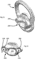
Figure 21 , thebody 230 is the same as that in the embodiment ofFigures 19 and 20 , and similar nuts and screws 260 are also included. However, the retention component of this embodiment is aknot blocking plate 280, shown inFigures 22 and23 . - The
knot blocking plate 280 has a periphery of size and shape such that when it is placed on thebody 230 it completely covers thebridge hole 240. An inner surface of theknot blocking plate 280 has a projectingboss 282 surrounded by a flat mating surface. Theboss 282 is a close fit within the bridge hole such that when theknot blocking plate 280 is placed onto thebody 230, the mating surface comes into contact with the outer surface of thebody 230 and theboss 282 enters thebridge hole 240 to locate theknot blocking plate 280 in the correct position on thebody 230. - Two bolt holes 248 pass through the
knot blocking plate 280. An end portion of eachbolt hole 248 adjacent to the outer surface is countersunk at 286. Arecess 288 surrounds eachbolt hole 248 where it opens to the inner surface of theknot blocking plate 280. As with theattachment bar 230 described above, the presence of theridges 254 and recesses 288 serve to locate theknot blocking plate 280 in the correct position on thebody 230 and also prevents theknot blocking plate 280 being installed in the incorrect orientation. The length and diameter of the head of thescrews 260 is selected such that if an attempt is made to fit theknot blocking plate 280 to the wrong surface of thebody 230, the head will not enter thecounterbores 262 of the bolt holes 248, and are not long enough to project from theattachment bar 232 so preventing thenuts 258 from being installed. - The
knot blocking plate 280 has acentral rope aperture 288 that extends between the inner and outer surfaces. Therope aperture 288 is shaped as a rounded rectangle and dimensioned such that two lengths of rope that will be used to form the bridge can pass through it side-by-side with little space between the ropes and the material surrounding therope aperture 288. Adjacent to where it opens to the inner and outer surfaces of theknot blocking plate 280, therope aperture 288 is flared in order that it presents no sharp or small-radius edges to a rope passing through it. - The rope bridge on a harness that uses the forward connection arrangement shown in
Figures 21 to 23 is formed by passing two ropes through therope aperture 288 of eachknot blocking plate 280 and tying suitable stopper knots in the ropes to the outside of theknot blocking plates 280, as shown inFigure 24 . - Although some components described above have been formed from rope and some from webbing, the skilled person will realise that, in many cases, one can be substituted for the other.
Claims (15)
- A harness for supporting a person working at height comprising a back (12), leg loops (10), two forward connection arrangements (27) and a flexible load-bearing member (28) that extends between the connection arrangements (27), the forward connection arrangements serving to transferring load from the back and the leg loops to the load-bearing member, characterised in that each forward connection arrangement comprises: a body (30) that is permanently connected to the harness and a retention component (32) that can be removably and rigidly connected to the body to removably secure the flexible load-bearing member (28) to the body (30).
- A harness according to claim 1 in which the flexible load-bearing member (28) includes a loop (66) and the retention components include a bar that when separate from the body can pass through the loop, and that, when connected to the body, is secured within the loop.
- A harness according to claim 2 in which the loop is formed to include an energy dissipation region which will fail upon application of a force above a threshold but below a maximum working force to cause the effective length of the flexible load-bearing member to increase.
- A harness according to claim 3 in which the energy dissipation region includes stitching (78) that will progressively fail when the load in the flexible load-bearing member being in excess of the threshold.
- A harness according to any preceding claim in which the retention components include a knot blocking component (280), the flexible load-bearing member (28) passing through an aperture (288) in the knot blocking component and being knotted to prevent its removal from the knot blocking component.
- A harness according to any preceding claim in which the retention components include an adjuster (132) that can be caused to grip the flexible load-bearing member at one of a range of positions.
- A harness according to claim 6 in which the adjuster allows the effective length of the flexible load-bearing member to decrease by application of a tensile force to a free end of the flexible load-bearing member.
- A harness according to claim 6 or claim 7 in which the adjuster allows the effective length of the flexible load-bearing member to increase upon manual intervention by a user prior to application of a tensile force to the flexible load-bearing member.
- A harness according to any preceding claim in which the secured flexible load-bearing member passes through the body (30).
- A harness according to any preceding claim having two similar forward connection arrangements.
- A harness according to any one of claims 1 to 9 having two dissimilar forward connection arrangements.
- A harness according to claim 11 in which one forward connection arrangement is as defined in accordance with any one of claims 2 to 4 and another forward connection arrangement is as defined in accordance with any one of claims 5 to 9.
- A harness according to any preceding claim in which the body (30) of each forward connection arrangement is permanently connected to a waist webbing (14) that extends about the back of the harness.
- A harness according to any preceding claim in which the body of each forward connection arrangement is permanently connected to a respective riser (18) that is connected to a respective leg loop (10).
- A harness according to any preceding claim having a plurality of flexible connecting members each of which is removably secured to the harness by the or each forward connection arrangement.
Priority Applications (1)
| Application Number | Priority Date | Filing Date | Title |
|---|---|---|---|
| EP25170788.1A EP4599901A3 (en) | 2016-12-06 | 2017-12-05 | Harness |
Applications Claiming Priority (1)
| Application Number | Priority Date | Filing Date | Title |
|---|---|---|---|
| GB1620695.5A GB2557308B (en) | 2016-12-06 | 2016-12-06 | Harnesses |
Related Child Applications (2)
| Application Number | Title | Priority Date | Filing Date |
|---|---|---|---|
| EP25170788.1A Division EP4599901A3 (en) | 2016-12-06 | 2017-12-05 | Harness |
| EP25170788.1A Previously-Filed-Application EP4599901A3 (en) | 2016-12-06 | 2017-12-05 | Harness |
Publications (3)
| Publication Number | Publication Date |
|---|---|
| EP3332840A1 true EP3332840A1 (en) | 2018-06-13 |
| EP3332840C0 EP3332840C0 (en) | 2025-04-16 |
| EP3332840B1 EP3332840B1 (en) | 2025-04-16 |
Family
ID=58159800
Family Applications (2)
| Application Number | Title | Priority Date | Filing Date |
|---|---|---|---|
| EP25170788.1A Pending EP4599901A3 (en) | 2016-12-06 | 2017-12-05 | Harness |
| EP17205383.7A Active EP3332840B1 (en) | 2016-12-06 | 2017-12-05 | Harness |
Family Applications Before (1)
| Application Number | Title | Priority Date | Filing Date |
|---|---|---|---|
| EP25170788.1A Pending EP4599901A3 (en) | 2016-12-06 | 2017-12-05 | Harness |
Country Status (3)
| Country | Link |
|---|---|
| US (2) | US11534633B2 (en) |
| EP (2) | EP4599901A3 (en) |
| GB (2) | GB2557308B (en) |
Cited By (6)
| Publication number | Priority date | Publication date | Assignee | Title |
|---|---|---|---|---|
| GB2577516A (en) * | 2018-09-26 | 2020-04-01 | Treemagineers Ltd | Apparatus for supporting a person at height |
| GB2602307A (en) * | 2020-12-22 | 2022-06-29 | Treemagineers Ltd | Harnesses |
| EP4035743A1 (en) | 2021-01-29 | 2022-08-03 | Treemagineers Ltd | Harnesses |
| EP4151282A3 (en) * | 2021-07-22 | 2023-04-05 | Honeywell International Inc. | Relief apparatus for mobility and suspension mitigation |
| EP4169584A1 (en) | 2021-10-19 | 2023-04-26 | Teufelberger Fiber Rope GmbH | Belt with a connector for protecting a person against falling |
| EP4327892A1 (en) | 2022-08-24 | 2024-02-28 | Teufelberger Fiber Rope GmbH | Anti-fall harness comprising a two-part fitting |
Families Citing this family (16)
| Publication number | Priority date | Publication date | Assignee | Title |
|---|---|---|---|---|
| GB2557308B (en) * | 2016-12-06 | 2020-06-24 | Treemagineers Ltd | Harnesses |
| US10648535B2 (en) * | 2017-05-30 | 2020-05-12 | LeBeau Inc. | Carabiner with pinching mechanism |
| US20190001165A1 (en) * | 2017-06-28 | 2019-01-03 | Alexander Andrew, Inc. Dba Falltech | Attachment lock with self-retracting device adapter |
| AU2018335539B2 (en) * | 2017-09-22 | 2022-03-03 | 3M Innovative Properties Company | Fall arresting device connector |
| FR3072034B1 (en) * | 2017-10-06 | 2019-11-08 | Zedel | HARNESS |
| GB2572826B (en) | 2018-04-13 | 2021-02-10 | Treemagineers Ltd | Pulley assembly with rope passage of varying cross-section |
| US20200107615A1 (en) * | 2018-10-09 | 2020-04-09 | Checkmate Lifting & Safety Ltd | Combination strap connector and adjuster |
| US11730983B2 (en) * | 2019-08-14 | 2023-08-22 | Buckingham Manufacturing Company, Inc. | D-rings with multiple openings |
| US11504556B2 (en) * | 2020-01-07 | 2022-11-22 | Tethrd LLC | Bridge rope assembly |
| USD951069S1 (en) * | 2020-05-19 | 2022-05-10 | Zedel | Anchor rigging plate for climbing |
| USD964300S1 (en) * | 2021-03-05 | 2022-09-20 | Best Energy Reduction Technologies, Llc | Outlet harness device |
| US20220305307A1 (en) * | 2021-03-24 | 2022-09-29 | Pigeon Mountain Industries, Inc. | Self-adjusting safety harness |
| FR3132229B1 (en) * | 2022-02-01 | 2024-10-04 | Zedel | VENTRAL SUSPENSION POINT ROPE HARNESS |
| TWI860890B (en) * | 2023-11-16 | 2024-11-01 | 振鋒企業股份有限公司 | Multifunctional connecting ring |
| FR3161121B1 (en) | 2024-04-10 | 2026-06-12 | Zedel | ADJUSTMENT DEVICE FOR A WIRED ELEMENT AND ROPE HARNESS EQUIPPED WITH SUCH AN ADJUSTMENT DEVICE |
| USD1130181S1 (en) * | 2024-07-22 | 2026-06-16 | Buckingham Manufacturing Company, Inc. | D-ring with multiple openings |
Citations (4)
| Publication number | Priority date | Publication date | Assignee | Title |
|---|---|---|---|---|
| US8333262B1 (en) * | 2008-11-12 | 2012-12-18 | Buckingham Manufacturing Company, Inc. | Reconfigurable, modular ergonomic sit harness or saddle |
| US8464832B1 (en) * | 2010-02-05 | 2013-06-18 | Buckingham Manufacturing Company, Inc. | Length adjusting device having a rotated and elongated eye |
| US20150231422A1 (en) * | 2014-02-19 | 2015-08-20 | D B Industries, Llc | Utility belt |
| EP3162411A1 (en) * | 2015-10-30 | 2017-05-03 | Treemagineers Ltd | Protective equipment |
Family Cites Families (26)
| Publication number | Priority date | Publication date | Assignee | Title |
|---|---|---|---|---|
| US2254179A (en) * | 1940-05-23 | 1941-08-26 | John F Fonder | Safety seat |
| US2581772A (en) * | 1946-10-04 | 1952-01-08 | Rose Mfg Company | Safety belt |
| GB1100041A (en) | 1964-02-24 | 1968-01-24 | Harley Patents Int | Improvements relating to connector devices |
| DE3140668A1 (en) * | 1981-10-13 | 1983-04-28 | Klaus 8221 Waging Mader | BRACKET WITH HOOK |
| US4546851A (en) * | 1982-11-03 | 1985-10-15 | Brennan Daniel F | Tree climbing apparatus |
| US5154660A (en) * | 1990-08-03 | 1992-10-13 | Pet Affairs, Inc. | Pet restraining apparatus |
| US5131490A (en) * | 1990-08-17 | 1992-07-21 | Michael Bell | Harness and seat board repelling system |
| CA2114898A1 (en) * | 1994-02-03 | 1995-08-04 | Richard Vallance | Fall-arrest strap and fall prevention method |
| DE29917619U1 (en) | 1999-10-06 | 1999-12-30 | König, Christian, 74676 Niedernhall | Clamping device |
| US20040163898A1 (en) * | 2002-12-12 | 2004-08-26 | Jacob Bergquist | Bidirectionally locking safety brake apparatus for tree climbing lanyards and other types of lines and safety climbing lanyard system utilizing same |
| US7076845B2 (en) | 2003-01-13 | 2006-07-18 | Timothy T. Tylaska | Mechanical knot apparatus |
| EP1660192B1 (en) * | 2003-09-05 | 2015-11-04 | D B Industries, LLC | Dorsal pad assembly for use with a safety harness |
| ITMI20050633A1 (en) * | 2005-04-13 | 2006-10-14 | Camp Spa | HARNESS |
| WO2007110580A1 (en) * | 2006-03-24 | 2007-10-04 | The Heightec Group Limited | Safety lanyard |
| US9144711B2 (en) * | 2008-03-19 | 2015-09-29 | Black Diamond Equipment, Ltd. | Via ferrata safety system |
| FR2932689B1 (en) * | 2008-06-18 | 2010-08-20 | Zedel | ENHANCEMENT HARNESS WITH IMPROVED SEAT SADDLE |
| EP2760742B1 (en) * | 2011-09-30 | 2018-12-12 | Airborne Systems North America of NJ Inc. | Parachute harness container with bio-contoured load distributing vest |
| US8938864B2 (en) * | 2011-10-28 | 2015-01-27 | D B Industries, Llc | Connector |
| FR2991590A3 (en) * | 2012-06-11 | 2013-12-13 | Miguel Baranda Maria Teresa San | Safety belt for securing individual to fixed support e.g. mast, for fall protection in boat, has line fixed at waist belt and provided with attachment points, and connector secured to one attachment point to form loop around fixed support |
| USD685676S1 (en) | 2012-10-03 | 2013-07-09 | Timothy T. Tylaska | Fastening apparatus |
| US9707421B2 (en) * | 2013-02-08 | 2017-07-18 | D B Industries, Llc | Energy absorber cover |
| EP2781235A3 (en) * | 2013-03-19 | 2017-08-02 | A. Haberkorn & Co GmbH | Climbing harness with spacer |
| US9993669B2 (en) * | 2015-06-10 | 2018-06-12 | D B Industries, Llc | D-ring keeper assembly |
| US10232199B2 (en) * | 2015-06-10 | 2019-03-19 | D B Industries, Llc | Integral safety harness connector assembly |
| FR3049870A1 (en) * | 2016-04-08 | 2017-10-13 | Zedel | HARNESS |
| GB2557308B (en) * | 2016-12-06 | 2020-06-24 | Treemagineers Ltd | Harnesses |
-
2016
- 2016-12-06 GB GB1620695.5A patent/GB2557308B/en active Active
-
2017
- 2017-12-05 EP EP25170788.1A patent/EP4599901A3/en active Pending
- 2017-12-05 EP EP17205383.7A patent/EP3332840B1/en active Active
- 2017-12-05 GB GB1720207.8A patent/GB2559038B/en active Active
- 2017-12-06 US US15/832,808 patent/US11534633B2/en active Active
-
2022
- 2022-10-26 US US18/049,672 patent/US20230065262A1/en active Pending
Patent Citations (4)
| Publication number | Priority date | Publication date | Assignee | Title |
|---|---|---|---|---|
| US8333262B1 (en) * | 2008-11-12 | 2012-12-18 | Buckingham Manufacturing Company, Inc. | Reconfigurable, modular ergonomic sit harness or saddle |
| US8464832B1 (en) * | 2010-02-05 | 2013-06-18 | Buckingham Manufacturing Company, Inc. | Length adjusting device having a rotated and elongated eye |
| US20150231422A1 (en) * | 2014-02-19 | 2015-08-20 | D B Industries, Llc | Utility belt |
| EP3162411A1 (en) * | 2015-10-30 | 2017-05-03 | Treemagineers Ltd | Protective equipment |
Cited By (18)
| Publication number | Priority date | Publication date | Assignee | Title |
|---|---|---|---|---|
| WO2020065279A1 (en) | 2018-09-26 | 2020-04-02 | Treemagineers Ltd | Apparatus for supporting a person at height |
| GB2577516B (en) * | 2018-09-26 | 2021-03-17 | Treemagineers Ltd | Apparatus for supporting a person at height |
| CN112770816A (en) * | 2018-09-26 | 2021-05-07 | 特里麦吉尼尔斯有限公司 | Device for supporting a person at an altitude |
| GB2577516A (en) * | 2018-09-26 | 2020-04-01 | Treemagineers Ltd | Apparatus for supporting a person at height |
| CN112770816B (en) * | 2018-09-26 | 2025-02-07 | 特里麦吉尼尔斯有限公司 | Equipment for supporting people at height |
| GB2602307B (en) * | 2020-12-22 | 2024-03-06 | Treemagineers Ltd | Harnesses |
| GB2602307A (en) * | 2020-12-22 | 2022-06-29 | Treemagineers Ltd | Harnesses |
| EP4019093A1 (en) * | 2020-12-22 | 2022-06-29 | Treemagineers Ltd | Harnesses |
| EP4035743A1 (en) | 2021-01-29 | 2022-08-03 | Treemagineers Ltd | Harnesses |
| GB2608095A (en) * | 2021-01-29 | 2022-12-28 | Treeemagineers Ltd | Harnesses |
| US12377298B2 (en) | 2021-01-29 | 2025-08-05 | Treemagineers Ltd. | Harnesses |
| GB2608095B (en) * | 2021-01-29 | 2023-09-13 | Treeemagineers Ltd | Harnesses |
| EP4151282A3 (en) * | 2021-07-22 | 2023-04-05 | Honeywell International Inc. | Relief apparatus for mobility and suspension mitigation |
| US12697514B2 (en) | 2021-07-22 | 2026-08-04 | Honeywell Safety Products Usa, Inc. | Relief apparatus for mobility and suspension mitigation |
| WO2023066564A1 (en) | 2021-10-19 | 2023-04-27 | Teufelberger Fiber Rope Gmbh | Belt for preventing persons from falling, having a fitting part |
| EP4169584A1 (en) | 2021-10-19 | 2023-04-26 | Teufelberger Fiber Rope GmbH | Belt with a connector for protecting a person against falling |
| WO2024041913A1 (en) | 2022-08-24 | 2024-02-29 | Teufelberger Fiber Rope Gmbh | Belt for preventing persons from falling comprising a two-piece fitting part |
| EP4327892A1 (en) | 2022-08-24 | 2024-02-28 | Teufelberger Fiber Rope GmbH | Anti-fall harness comprising a two-part fitting |
Also Published As
| Publication number | Publication date |
|---|---|
| GB2557308B (en) | 2020-06-24 |
| GB201620695D0 (en) | 2017-01-18 |
| GB201720207D0 (en) | 2018-01-17 |
| GB2559038B (en) | 2020-02-05 |
| US20230065262A1 (en) | 2023-03-02 |
| GB2559038A (en) | 2018-07-25 |
| EP4599901A2 (en) | 2025-08-13 |
| US20180154196A1 (en) | 2018-06-07 |
| US11534633B2 (en) | 2022-12-27 |
| GB2557308A (en) | 2018-06-20 |
| EP3332840C0 (en) | 2025-04-16 |
| EP4599901A3 (en) | 2025-11-05 |
| EP3332840B1 (en) | 2025-04-16 |
Similar Documents
| Publication | Publication Date | Title |
|---|---|---|
| US20230065262A1 (en) | Harnesses | |
| EP3162411A1 (en) | Protective equipment | |
| US20210393998A1 (en) | Apparatus for supporting a person at height | |
| US11191325B2 (en) | Harness connection arrangement | |
| RU2729094C2 (en) | Strapping | |
| US9248324B1 (en) | Swivel D-ring attachment point | |
| CN111225719B (en) | Protective belt with pivoting hip connection | |
| EP3820578B1 (en) | Harness connection arrangement | |
| US9295305B2 (en) | D-ring with rescue attachment and lanyard attachments integrated | |
| US20190070444A1 (en) | Fall protection lanyard capable of direct connection to harness webbing | |
| US10112078B1 (en) | Step assembly with fall arrest capability including removable step | |
| AU2016276446A9 (en) | Breakaway keeper | |
| EP4035743B1 (en) | Harnesses | |
| US20100300804A1 (en) | Di-Electric Harness For Fall Arrest Systems | |
| EP4096796B1 (en) | Lanyard assembly | |
| WO2012063064A2 (en) | Safety line connector | |
| AU2018101477A4 (en) | Inline descender | |
| US20240285985A1 (en) | Harnesses | |
| TWM526673U (en) | Limiting structure of fast disassembling device of mobile equipment |
Legal Events
| Date | Code | Title | Description |
|---|---|---|---|
| PUAI | Public reference made under article 153(3) epc to a published international application that has entered the european phase |
Free format text: ORIGINAL CODE: 0009012 |
|
| STAA | Information on the status of an ep patent application or granted ep patent |
Free format text: STATUS: THE APPLICATION HAS BEEN PUBLISHED |
|
| AK | Designated contracting states |
Kind code of ref document: A1 Designated state(s): AL AT BE BG CH CY CZ DE DK EE ES FI FR GB GR HR HU IE IS IT LI LT LU LV MC MK MT NL NO PL PT RO RS SE SI SK SM TR |
|
| AX | Request for extension of the european patent |
Extension state: BA ME |
|
| STAA | Information on the status of an ep patent application or granted ep patent |
Free format text: STATUS: REQUEST FOR EXAMINATION WAS MADE |
|
| 17P | Request for examination filed |
Effective date: 20181213 |
|
| RBV | Designated contracting states (corrected) |
Designated state(s): AL AT BE BG CH CY CZ DE DK EE ES FI FR GB GR HR HU IE IS IT LI LT LU LV MC MK MT NL NO PL PT RO RS SE SI SK SM TR |
|
| STAA | Information on the status of an ep patent application or granted ep patent |
Free format text: STATUS: EXAMINATION IS IN PROGRESS |
|
| 17Q | First examination report despatched |
Effective date: 20190214 |
|
| TPAC | Observations filed by third parties |
Free format text: ORIGINAL CODE: EPIDOSNTIPA |
|
| P01 | Opt-out of the competence of the unified patent court (upc) registered |
Effective date: 20230530 |
|
| GRAP | Despatch of communication of intention to grant a patent |
Free format text: ORIGINAL CODE: EPIDOSNIGR1 |
|
| STAA | Information on the status of an ep patent application or granted ep patent |
Free format text: STATUS: GRANT OF PATENT IS INTENDED |
|
| INTG | Intention to grant announced |
Effective date: 20240619 |
|
| GRAJ | Information related to disapproval of communication of intention to grant by the applicant or resumption of examination proceedings by the epo deleted |
Free format text: ORIGINAL CODE: EPIDOSDIGR1 |
|
| STAA | Information on the status of an ep patent application or granted ep patent |
Free format text: STATUS: EXAMINATION IS IN PROGRESS |
|
| GRAS | Grant fee paid |
Free format text: ORIGINAL CODE: EPIDOSNIGR3 |
|
| STAA | Information on the status of an ep patent application or granted ep patent |
Free format text: STATUS: GRANT OF PATENT IS INTENDED |
|
| GRAP | Despatch of communication of intention to grant a patent |
Free format text: ORIGINAL CODE: EPIDOSNIGR1 |
|
| INTC | Intention to grant announced (deleted) | ||
| INTG | Intention to grant announced |
Effective date: 20241111 |
|
| GRAA | (expected) grant |
Free format text: ORIGINAL CODE: 0009210 |
|
| STAA | Information on the status of an ep patent application or granted ep patent |
Free format text: STATUS: THE PATENT HAS BEEN GRANTED |
|
| AK | Designated contracting states |
Kind code of ref document: B1 Designated state(s): AL AT BE BG CH CY CZ DE DK EE ES FI FR GB GR HR HU IE IS IT LI LT LU LV MC MK MT NL NO PL PT RO RS SE SI SK SM TR |
|
| REG | Reference to a national code |
Ref country code: GB Ref legal event code: FG4D |
|
| REG | Reference to a national code |
Ref country code: CH Ref legal event code: EP |
|
| REG | Reference to a national code |
Ref country code: IE Ref legal event code: FG4D |
|
| REG | Reference to a national code |
Ref country code: DE Ref legal event code: R096 Ref document number: 602017088921 Country of ref document: DE |
|
| U01 | Request for unitary effect filed |
Effective date: 20250515 |
|
| P04 | Withdrawal of opt-out of the competence of the unified patent court (upc) registered |
Free format text: CASE NUMBER: APP_26165/2025 Effective date: 20250602 |
|
| RAP4 | Party data changed (patent owner data changed or rights of a patent transferred) |
Owner name: TREEMAGINEERS LTD |
|
| U07 | Unitary effect registered |
Designated state(s): AT BE BG DE DK EE FI FR IT LT LU LV MT NL PT RO SE SI Effective date: 20250605 |
|
| PG25 | Lapsed in a contracting state [announced via postgrant information from national office to epo] |
Ref country code: ES Free format text: LAPSE BECAUSE OF FAILURE TO SUBMIT A TRANSLATION OF THE DESCRIPTION OR TO PAY THE FEE WITHIN THE PRESCRIBED TIME-LIMIT Effective date: 20250416 |
|
| PG25 | Lapsed in a contracting state [announced via postgrant information from national office to epo] |
Ref country code: NO Free format text: LAPSE BECAUSE OF FAILURE TO SUBMIT A TRANSLATION OF THE DESCRIPTION OR TO PAY THE FEE WITHIN THE PRESCRIBED TIME-LIMIT Effective date: 20250716 Ref country code: GR Free format text: LAPSE BECAUSE OF FAILURE TO SUBMIT A TRANSLATION OF THE DESCRIPTION OR TO PAY THE FEE WITHIN THE PRESCRIBED TIME-LIMIT Effective date: 20250717 |
|
| PG25 | Lapsed in a contracting state [announced via postgrant information from national office to epo] |
Ref country code: PL Free format text: LAPSE BECAUSE OF FAILURE TO SUBMIT A TRANSLATION OF THE DESCRIPTION OR TO PAY THE FEE WITHIN THE PRESCRIBED TIME-LIMIT Effective date: 20250416 |
|
| PG25 | Lapsed in a contracting state [announced via postgrant information from national office to epo] |
Ref country code: HR Free format text: LAPSE BECAUSE OF FAILURE TO SUBMIT A TRANSLATION OF THE DESCRIPTION OR TO PAY THE FEE WITHIN THE PRESCRIBED TIME-LIMIT Effective date: 20250416 |
|
| PG25 | Lapsed in a contracting state [announced via postgrant information from national office to epo] |
Ref country code: RS Free format text: LAPSE BECAUSE OF FAILURE TO SUBMIT A TRANSLATION OF THE DESCRIPTION OR TO PAY THE FEE WITHIN THE PRESCRIBED TIME-LIMIT Effective date: 20250716 |
|
| PG25 | Lapsed in a contracting state [announced via postgrant information from national office to epo] |
Ref country code: IS Free format text: LAPSE BECAUSE OF FAILURE TO SUBMIT A TRANSLATION OF THE DESCRIPTION OR TO PAY THE FEE WITHIN THE PRESCRIBED TIME-LIMIT Effective date: 20250816 |
|
| U20 | Renewal fee for the european patent with unitary effect paid |
Year of fee payment: 9 Effective date: 20251007 |
|
| REG | Reference to a national code |
Ref country code: CH Ref legal event code: U11 Free format text: ST27 STATUS EVENT CODE: U-0-0-U10-U11 (AS PROVIDED BY THE NATIONAL OFFICE) Effective date: 20260101 |
|
| PG25 | Lapsed in a contracting state [announced via postgrant information from national office to epo] |
Ref country code: SM Free format text: LAPSE BECAUSE OF FAILURE TO SUBMIT A TRANSLATION OF THE DESCRIPTION OR TO PAY THE FEE WITHIN THE PRESCRIBED TIME-LIMIT Effective date: 20250416 |
|
| PG25 | Lapsed in a contracting state [announced via postgrant information from national office to epo] |
Ref country code: CZ Free format text: LAPSE BECAUSE OF FAILURE TO SUBMIT A TRANSLATION OF THE DESCRIPTION OR TO PAY THE FEE WITHIN THE PRESCRIBED TIME-LIMIT Effective date: 20250416 |
|
| PG25 | Lapsed in a contracting state [announced via postgrant information from national office to epo] |
Ref country code: SK Free format text: LAPSE BECAUSE OF FAILURE TO SUBMIT A TRANSLATION OF THE DESCRIPTION OR TO PAY THE FEE WITHIN THE PRESCRIBED TIME-LIMIT Effective date: 20250416 |
|
| PLBE | No opposition filed within time limit |
Free format text: ORIGINAL CODE: 0009261 |
|
| STAA | Information on the status of an ep patent application or granted ep patent |
Free format text: STATUS: NO OPPOSITION FILED WITHIN TIME LIMIT |
|
| REG | Reference to a national code |
Ref country code: CH Ref legal event code: L10 Free format text: ST27 STATUS EVENT CODE: U-0-0-L10-L00 (AS PROVIDED BY THE NATIONAL OFFICE) Effective date: 20260225 |
|
| 26N | No opposition filed |
Effective date: 20260119 |
|
| PGFP | Annual fee paid to national office [announced via postgrant information from national office to epo] |
Ref country code: CH Payment date: 20260101 Year of fee payment: 9 |
|
| PG25 | Lapsed in a contracting state [announced via postgrant information from national office to epo] |
Ref country code: MC Free format text: LAPSE BECAUSE OF FAILURE TO SUBMIT A TRANSLATION OF THE DESCRIPTION OR TO PAY THE FEE WITHIN THE PRESCRIBED TIME-LIMIT Effective date: 20250416 |