EP3332716A1 - Suturing device - Google Patents
Suturing device Download PDFInfo
- Publication number
- EP3332716A1 EP3332716A1 EP16830107.5A EP16830107A EP3332716A1 EP 3332716 A1 EP3332716 A1 EP 3332716A1 EP 16830107 A EP16830107 A EP 16830107A EP 3332716 A1 EP3332716 A1 EP 3332716A1
- Authority
- EP
- European Patent Office
- Prior art keywords
- suture
- gripping members
- suture needle
- tissue
- projection
- Prior art date
- Legal status (The legal status is an assumption and is not a legal conclusion. Google has not performed a legal analysis and makes no representation as to the accuracy of the status listed.)
- Granted
Links
Images





Classifications
-
- A—HUMAN NECESSITIES
- A61—MEDICAL OR VETERINARY SCIENCE; HYGIENE
- A61B—DIAGNOSIS; SURGERY; IDENTIFICATION
- A61B17/00—Surgical instruments, devices or methods
- A61B17/04—Surgical instruments, devices or methods for suturing wounds; Holders or packages for needles or suture materials
- A61B17/06—Needles ; Sutures; Needle-suture combinations; Holders or packages for needles or suture materials
- A61B17/062—Needle manipulators
- A61B17/0625—Needle manipulators the needle being specially adapted to interact with the manipulator, e.g. being ridged to snap fit in a hole of the manipulator
-
- A—HUMAN NECESSITIES
- A61—MEDICAL OR VETERINARY SCIENCE; HYGIENE
- A61B—DIAGNOSIS; SURGERY; IDENTIFICATION
- A61B17/00—Surgical instruments, devices or methods
- A61B17/04—Surgical instruments, devices or methods for suturing wounds; Holders or packages for needles or suture materials
- A61B17/06—Needles ; Sutures; Needle-suture combinations; Holders or packages for needles or suture materials
- A61B17/062—Needle manipulators
-
- A—HUMAN NECESSITIES
- A61—MEDICAL OR VETERINARY SCIENCE; HYGIENE
- A61B—DIAGNOSIS; SURGERY; IDENTIFICATION
- A61B17/00—Surgical instruments, devices or methods
- A61B17/04—Surgical instruments, devices or methods for suturing wounds; Holders or packages for needles or suture materials
- A61B17/0469—Suturing instruments for use in minimally invasive surgery, e.g. endoscopic surgery
-
- A—HUMAN NECESSITIES
- A61—MEDICAL OR VETERINARY SCIENCE; HYGIENE
- A61B—DIAGNOSIS; SURGERY; IDENTIFICATION
- A61B17/00—Surgical instruments, devices or methods
- A61B17/04—Surgical instruments, devices or methods for suturing wounds; Holders or packages for needles or suture materials
- A61B17/0491—Sewing machines for surgery
-
- A—HUMAN NECESSITIES
- A61—MEDICAL OR VETERINARY SCIENCE; HYGIENE
- A61B—DIAGNOSIS; SURGERY; IDENTIFICATION
- A61B17/00—Surgical instruments, devices or methods
- A61B17/00234—Surgical instruments, devices or methods for minimally invasive surgery
- A61B2017/00292—Surgical instruments, devices or methods for minimally invasive surgery mounted on or guided by flexible, e.g. catheter-like, means
- A61B2017/0034—Surgical instruments, devices or methods for minimally invasive surgery mounted on or guided by flexible, e.g. catheter-like, means adapted to be inserted through a working channel of an endoscope
-
- A—HUMAN NECESSITIES
- A61—MEDICAL OR VETERINARY SCIENCE; HYGIENE
- A61B—DIAGNOSIS; SURGERY; IDENTIFICATION
- A61B17/00—Surgical instruments, devices or methods
- A61B2017/00831—Material properties
- A61B2017/00862—Material properties elastic or resilient
Definitions
- the present invention relates to a medical suture device.
- suture devices for suturing tissue or the like in a body have been known (see PTL 1 and PTL 2).
- a suture device includes two openable/closable gripping members at a distal end of an elongated shaft member that is inserted into the body of a patient.
- the gripping members are provided with a passing mechanism which passes a suture needle.
- a suture object is sandwiched by two gripping members in a state where the suture needle to which a suture thread is attached is held by one of the gripping members. With such an operation, the suture needle is made to penetrate the suture object.
- the suture object is sutured.
- a pointed end portion of a suture needle held by one of the gripping member is pressed against a suture object disposed between the pointed end portion of the suture needle and the other gripping member.
- the suture object is pierced by the pointed end portion. In such a manner, the suture needle is made to penetrate the suture object.
- a suture object is a soft tissue or the like
- the suture needle is passed in a state where the suture object is pushed into the needle receiving hole, the suture object is jammed and a problem that a suturing operation cannot be performed arises.
- the present invention has been made in view of the above-mentioned circumstances, and it is an object of the present invention to provide a suture device where a suture needle is made to ensure penetrating a suture object so that a suturing operation can be performed smoothly.
- the present invention provides the following solutions.
- a suture device which includes: an elongated shaft member extending along a longitudinal axis; a pair of two gripping members, the gripping members being provided at a distal end of the elongated shaft member in a pivotable manner about a pivot orthogonal to the longitudinal axis so as to be opened and closed relative to each other; and a passing mechanism configured to pass a suture needle between the gripping members, the suture needle to which a suture thread is attached and which has a pointed end portion
- each of the gripping members includes: a fitting hole portions which is formed along an opening and closing direction of the gripping members, and to which the suture needle is detachably fitted; and a contact portion which is brought into contact with either of front and back surfaces of a suture object in a course of a closing action of the pair of the gripping members so as to suppress a movement of the suture object in a direction along the surface of the suture object.
- the fitting hole portion of one gripping member holds the suture needle in a fitted state with the pointed end portion of the suture needle toward the other gripping member side.
- both gripping members are closed so as to grip a suture object therebetween, the suture needle penetrates the suture object, and is fitted into the fitting hole of the other gripping member.
- the passing mechanism releases the holding of the suture needle by one of the gripping members and holds the suture needle by the other gripping member.
- the suture needle is passed from one of the gripping members to the other gripping member so that the suture thread attached to the suture needle can be made to penetrate the suture object.
- the movement of the suture object is suppressed by the contact portions and hence, a tension of the suture object in a region where the pointed end portion of the suture needle is in contact with the suture object is increased, and thus the suture object is easily pierced by the pointed end portion.
- the suture needle can be made to ensure penetrating the suture object so that jamming of the suture object by the passing mechanism can be prevented. Accordingly, a suturing operation can be performed smoothly.
- the contact portions may include: a tubular portion formed so that the tubular portion surrounds a periphery of the fitting hole portion of one of the gripping members provided with the fitting hole portion into which the pointed end portion is inserted and that the tubular portion extends towards the other of the gripping members; and a projection portion, formed at a position where the projection portion surrounds the periphery of the fitting hole portion of the other of the gripping members, and extending toward one of the gripping members, and the tubular portion and the projection portion may be formed such that the tubular portion and the projection portion are arranged at positions spaced from each other in a radial direction of the fitting hole portions when the two gripping members are completely closed.
- the tip of the suture needle is pressed against the suture object which is stretched due to tension.
- the suture needle can be made to ensure penetrating the suture object and hence, a suturing operation can be performed smoothly.
- the tubular portion and the projection portion are disposed at positions away from each other in the radial direction. Accordingly, it is possible to prevent the suture object sandwiched between both the tubular portion and the projection portion from being crushed and damaged.
- the tubular portion may be formed into a cylindrical shape
- the projection portion may be formed into a cylindrical shape having an inner diameter larger than an outer diameter of the tubular portion
- the back surface of the suture object is pressed against the distal end of the cylindrical tubular portion over substantially the whole circumference.
- the suture object is pressed by the cylindrical projection portion over substantially the whole circumference from the front surface side on the radially outer side of the tubular portion. Accordingly, the tip of the suture needle is pressed against the suture object which is stretched like a drumhead due to tension.
- the suture needle can be made to ensure penetrating the suture object and hence, a suturing operation can be performed smoothly.
- the projection portion may be formed of two or more projection portions which are arranged at intervals in a circumferential direction of the fitting hole portion.
- the back surface of the suture object is pressed against the distal end of the cylindrical tubular portion over substantially the whole circumference.
- a tension is applied to the suture object from the front surface side in one or more directions by two or more projection portions on the radially outer side of the tubular portion. Accordingly, the tip of the suture needle is pressed against the suture object which is stretched due to tension.
- the suture needle can be made to ensure penetrating the suture object and hence, a suturing operation can be performed smoothly.
- the projection portion may be formed of an elastic member which is elastically deformed in contact with the suture object.
- the projection portion may be elastically deformed such that a distal end of the projection portion is moved in a radially outward direction.
- the projection portion formed of an elastic member is brought into contact with the front surface of the suture object at the radially outer side of the tubular portion which is in contact with the back surface side of the suture object, thus being elastically deformed such that the distal end of the projection portion is moved toward the outer side in the radial direction. Accordingly, a tension applied to the suture object arranged inside the tubular portion is increased. As a result, the suture needle can be made to ensure penetrating the suture object and hence, a suturing operation can be performed smoothly.
- the suture needle is made to ensure penetrating the suture object so that a suturing operation can be performed smoothly.
- a suture device 1 according to one embodiment of the present invention is described hereinafter with reference to drawings.
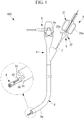
- FIG. 1 A suture system 100 in which the suture device 1 according to this embodiment is used is shown in Fig. 1 .
- the suture system 100 is a system which sutures tissue A using a suture needle 3 where a suture thread 2 is fixed to one end of the suture needle 3, and a pointed end portion 3a is formed on the other end of the suture needle 3.
- the suture system 100 includes an endoscope 4 and the suture device 1 according to this embodiment.
- the endoscope 4 is formed of a known endoscope, and includes a manipulation portion 6, which is manipulated by an operator, on the proximal end side of an elongated flexible insertion portion 5.
- a bending portion 5a is formed on a distal end portion of the insertion portion 5, and the bending portion 5a is bendable by a manipulation of a knob 6a of the manipulation portion 6.
- two channels 5b penetrating in the longitudinal direction and opening at the distal end surface are provided.
- reference symbol “5c" denotes an observation optical system.
- the number of channels 5b may be one or three or more.
- the suture device 1 includes: a long flexible tubular elongated shaft member 7 having an outer diameter size which allows the elongated shaft member 7 to be inserted into the channel 5b; a treatment portion 8 provided at a distal end of the elongated shaft member 7; and a manipulation portion 9 provided at a proximal end of the elongated shaft member 7.
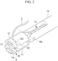
- the treatment portion 8 includes: a base 10 fixed to the distal end of the elongated shaft member 7; and two gripping members 11, 12 which are provided at the base 10 in a pivotable manner about an axis (pivot) 10a orthogonal to a longitudinal axis of the elongated shaft member 7.
- each of the two gripping members 11, 12 is connected to an opening-closing wire 14 via a link 13.
- both gripping members 11, 12 are disposed in a closed position where both gripping members 11, 12 extend approximately parallel along the longitudinal axis.
- both gripping members 11, 12 are swung and disposed in an open position.
- the link 13 which is connected to one gripping member 11 is indicated by chain lines.
- the two gripping members 11, 12 are provided with a passing mechanism 15 for passing the suture needle 3.
- the suture needle 3 is formed in a substantially columnar shape.
- the suture needle 3 has the conical pointed end portion 3a on one end thereof, and the suture thread 2 is fixed to the other end of the suture needle 3 by adhesion or the like.
- On a center portion of the suture needle 3 in the longitudinal direction a large-diameter portion 3b having a largest outer diameter size is formed with a predetermined length.
- Recessed portions 3c are formed on both sides of the large-diameter portion 3b in the longitudinal axis direction respectively at positions where the recessed portions 3c sandwich the large-diameter portion 3b. Each recessed portion 3c is recessed in the radial direction over the whole circumference.
- a flange portion 3d and a pointed end portion 3a are formed on the suture needle 3 at positions further toward the end portion sides of the suture needle 3 from the recessed portions 3c in the axial direction.
- the flange portion 3d and the pointed end portion 3a protrude more outside in the radial direction than the recessed portions 3c.
- the passing mechanism 15 is provided with: through holes (fitting hole portions) 11a, 12a formed in the two gripping members 11, 12 respectively at positions in the vicinity of pivotable distal end portions in a penetrating manner in the swing direction (opening-closing direction); holding members 16, 17 disposed in the respective gripping members 11, 12 in a movable manner in the longitudinal direction, which is orthogonal to the through holes 11a, 12a, along guide holes 11b, 12b formed along the longitudinal direction; and distal end wires 18a, 18b and drive wires 19a, 19b which drive the holding members 16, 17.
- the holding members 16, 17 are flat plate members which are made to translationally move in the longitudinal direction.
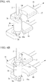
- the holding members 16, 17 have opening portions 16a, 17a which are open in the direction (sideward direction) intersecting with the moving direction so that the holding members 16, 17 are formed into a hook-shape as a whole.
- a plate thickness of the holding members 16, 17 is set smaller than a width size of the recessed portions 3c of the suture needle 3.
- the opening portions 16a, 17a of the holding members 16, 17 are formed with sizes which allow the flange portion 3d and the pointed end portion 3a to pass therethrough.
- the distal end wires 18a, 18b and the drive wires 19a, 19b are mutually connected to each other by connecting members 23a, 23b.
- the distal end wires 18a, 18b have sufficiently higher rigidity than the drive wires 19a, 19b, thus allowing a transmission of both a tensile force and a compressive force.
- the distal ends of the distal end wires 18a, 18b are fixed to the proximal end side of the holding members 16, 17, and proximal ends of the drive wires 19a, 19b are fixed to the manipulation portion 9 on the proximal end side of the elongated shaft member 7.
- a tensile force is applied to the drive wires 19a, 19b by a manipulation of the manipulation portion 9, the tensile force is transmitted to the holding members 16, 17 through the connecting members 23a, 23b and the distal end wires 18a, 18b, and the holding members 16, 17 are pulled and moved toward the proximal end side.
- the passing mechanism 15 also includes a swing member 24 arranged at a position further toward the proximal end side than the pivot 10a of the two gripping members 11, 12 such that the swing member 24 is swingable about a swing axis 24a orthogonal to the longitudinal axis of the elongated shaft member 7.
- the swing member 24 includes a ring-shaped member 25, and two columnar members 26, 27 disposed inside the ring-shaped member 25, and extending parallel to the axis 24a on both sides of the swing axis 24a with the axis 24a interposed therebetween.
- the respective columnar members 26, 27 are attached to the ring-shaped member 25 such that each of the columnar members 26, 27 is rotatable about a longitudinal axis of the columnar members 26, 27.
- Through holes 28, 29 which penetrate the columnar members 26, 27 in the diameter direction are formed in the columnar members 26, 27, and the drive wires 19a, 19b are made to pass through the through holes 28, 29.
- Opening sizes of the through holes 28, 29 are set larger than the outer diameter size of the drive wires 19a, 19b, and are set smaller than the outer diameter size of the connecting members 23a, 23b.
- the connecting members 23a, 23b are not allowed to pass through the through holes 28, 29 and are caught on side surface of the columnar members 26, 27, and the columnar members 26, 27 are pulled toward the proximal end side of the elongated shaft member 7 so that the ring-shaped member 25 is made to swing about the swing axis 24a.
- the columnar members 26, 27 are rotatable about the longitudinal axis of the columnar members 26, 27 so that a state is maintained where the through holes 28, 29 are extending along the longitudinal direction of the drive wires 19a, 19b.
- the distal end wire 18a has sufficiently high rigidity so that the distal end wire 18a transmits the compressive force without buckling whereby the holding member 16 at the distal end is pushed out toward the distal end side. Thereby, the holding and releasing of the suture needle 3 by two holding members 16, 17 can be switched alternatively.
- the suture needle 3 is fitted in the through holes 11a, 12a of the gripping members 11, 12, and an end portion of the suture needle 3 passes through the opening portions 16a, 17a of the holding members 16, 17 so that the suture needle 3 is disposed in a position where the recessed portions 3c of the suture needle 3 match with the holding members 16, 17; in such a state, when the drive wires 19a, 19b are pulled so that the holding members 16, 17 are moved toward the proximal end side, inner edges of the opening portions 16a, 17a on the distal end side are inserted into the recessed portions 3c.
- the flange portion 3d, the pointed end portion 3a and the large-diameter portion 3b are disposed in a position where the flange portion 3d and the large-diameter portion 3b sandwich the recessed portions 3c therebetween and the pointed end portion 3a and the large-diameter portion 3b sandwich the recessed portions 3c therebetween, the flange portion 3d or the pointed end portion 3a and the large-diameter portion 3b engage with the holding member 16 or the holding member 17 in the longitudinal direction of the suture needle 3 so that the suture needle 3 is engaged so as not to move in the longitudinal direction in the through holes 11a, 12a.
- a notch 20 is formed on each of the gripping members 11, 12 at a position (side position) which corresponds to the opening portions 16a, 17a of the holding members 16, 17 so as to penetrate the gripping members 11, 12 from outer surfaces of the gripping members 11, 12 to the through holes 11a, 12a.
- the minimum width of the notches 20 is set larger than the diameter size of the suture thread 2 so that the suture thread 2 can be moved in and out of the through holes 11a, 12a through the notches 20.
- the notches 20 have a shape which is gradually opened toward the outer surface of the gripping members 11, 12, thus facilitating the movement of the suture thread 2 in and out of the through holes 11a, 12a.
- the suture device 1 includes a first cylindrical portion (tubular portion) 30 and a second cylindrical portion (tubular portion) 31 which are formed on the gripping members 11, 12 respectively.
- the first cylindrical portion 30 extends in the axial direction of the through hole 11a into which the pointed end portion 3a side of the suture needle 3 is inserted from a surface of the other gripping member 11 which opposedly facing one of the gripping members 12.
- the second cylindrical portion 31 extends in the axial direction of the through hole 12a from a surface of the one of the gripping members 12 which opposedly facing the other gripping member 11.
- the first cylindrical portion 30 and the second cylindrical portion 31 form a contact portion which suppresses the movement of the tissue A in the direction along a surface of the tissue A.
- the first cylindrical portion 30 is disposed in a position where the first cylindrical portion 30 surrounds substantially the whole circumference of the through hole 11a.
- the second cylindrical portion 31 is disposed in a position where the second cylindrical portion 31 surrounds substantially the whole circumference of the through hole 12a.
- each of the first cylindrical portion 30 and the second cylindrical portion 31 is also partially cut in the circumferential direction corresponding to the notches 20.
- the second cylindrical portion 31 is formed with an inner diameter size larger than an outer diameter size of the first cylindrical portion 30.
- the first cylindrical portion 30 and the second cylindrical portion 31 are coaxially disposed with a gap therebetween in the radial direction and, at the same time, are disposed such that a distal end portion of the first cylindrical portion 30 and a distal end portion of the second cylindrical portion 31 partially overlap with each other in the axial direction.
- the manipulation portion 9 is disposed on the proximal end side of the elongated shaft member 7, and includes an opening-closing manipulation portion 21 for performing an opening-closing action of the two gripping members 11, 12; and a passing manipulation portion 22 for pulling the two drive wires 19a, 19b.
- the opening-closing manipulation portion 21 includes a handle 21a formed in the shape of scissor handles, and the opening-closing wire 14 is pushed and pulled in the longitudinal axis direction by an opening-closing manipulation of the handle 21a.
- the insertion portion 5 of the endoscope 4 is inserted into the body and, while the inside of the body is observed using the observation optical system 5c arranged at a distal end of the insertion portion 5, the distal end of the insertion portion 5 is disposed at a position where a portion to be sutured falls within the visual field range of the endoscope 4.
- the handle 21a of the opening-closing manipulation portion 21 is manipulated so as to close the two gripping members 11, 12 of the treatment portion 8 as shown in Fig. 3 , and the suture needle 3 is disposed such that the suture needle 3 passes through the through holes 11a, 12a of the two gripping members 11, 12 which are aligned in one row.
- a tensile force is applied to the other drive wire 19b which pulls the holding member 17 on the flange portion 3d side of the suture needle 3 toward the proximal end side.
- the tensile force is transmitted to the distal end wire 18b connected to the drive wire 19b so that the holding member 17 is pulled toward the proximal end side, while the connecting member 23b which connects the drive wire 19b and the distal end wire 18b with each other abuts against the side surface of the other columnar member 27 of the swing member 24.
- the tensile force of the drive wire 19b is applied to the other columnar member 27 and that the columnar member 27 is pulled toward the proximal end side, so that the swing member 24 is made to swing about the swing axis 24a at such a position thus pushing out one of the columnar members 26 toward the distal end side.
- the tensile force applied to the other drive wire 19b is transmitted to the other holding member 17 via the connecting member 23b and the other distal end wire 18b so that the holding member 17 is moved toward the proximal end side, whereby the holding member 17 is inserted into the recessed portion 3c on the flange portion 3d side of the suture needle 3.
- the connecting member 23a mounted on one of the drive wires 19a is pushed out toward the distal end side by the side surface of the columnar member 26 so that the holding member 16 is moved toward the distal end side and is brought into a state of releasing the suture needle 3 on the pointed end portion 3a side.
- the suture device 1 is inserted into the channel 5b from the treatment portion 8 side through an insertion port arranged on the proximal end side of the insertion portion 5 disposed outside the body, and the treatment portion 8 is made to project from the distal end surface of the insertion portion 5.
- the treatment portion 8 is also disposed within the visual field range of the observation optical system 5c of the endoscope 4.
- the tissue A which is a portion to be sutured is disposed in front of the treatment portion 8 while an endoscope image is observed; with a manipulation of the handle 21a of the opening-closing manipulation portion 21, the opening-closing wire 14 is pushed toward the distal end side so that the two gripping members 11, 12 are made to swing via the links 13 as shown in Figs. 5 and 11A so as to dispose the two gripping members 11, 12 in mutually opened positions.
- the holding member 16 on the pointed end portion 3a side is in a released state of the suture needle 3, and the holding member 17 on the flange portion 3d side is in a fixed state of the suture needle 3 to the gripping member 12 and hence, the two gripping members 11, 12 are opened in a state where the pointed end portion 3a of the suture needle 3 projects toward the inside.
- the treatment portion 8 is made to advance to a position where the tissue A is sandwiched between the two gripping members 11, 12, and then, with a manipulation of the opening-closing manipulation portion 21, the opening-closing wire 14 is drawn back toward the proximal end side so as to close the two gripping members 11, 12 via the links 13.
- the pointed end portion 3a of the suture needle 3 is brought into contact with the tissue A.
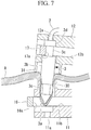
- the pair of gripping members 11, 12 are further closed, in the case where the tissue A is soft tissue or the like, as shown in Fig. 7 , a portion of the tissue A pressed by the pointed end portion 3a of the suture needle 3 is pushed into the through hole 11a of one gripping member 11.
- the suture device 1 of this embodiment in the course of the closing action shown in Fig. 6 , the first cylindrical portion 30 and the second cylindrical portion 31 are brought into contact with front and back surfaces of the tissue A and sandwich the tissue A.
- the pointed end portion 3a of the suture needle 3 punctures the tissue A from one side, and is inserted into the through hole 11a of the other gripping member 11 disposed on the other side of the tissue A so that the tissue A is sandwiched between the two gripping members 11, 12.
- first cylindrical portion 30 and the second cylindrical portion 31 are disposed in a position where the first cylindrical portion 30 and the second cylindrical portion 31 overlap with each other in the axial direction, and both cylindrical portions are disposed with a gap therebetween in the radial direction so that the tissue A sandwiched between both cylindrical portions is maintained in a fine state without being crushed.
- the handle 22a of the passing manipulation portion 22 is manipulated so as to apply a tensile force to the drive wire 19a which pulls the holding member 16 on the pointed end portion 3a side; the tensile force is transmitted to the drive wire 19a from the handle 22a so that the holding member 16 on the pointed end portion 3a side is pulled, whereby the holding member 16 is inserted into the recessed portion 3c on the pointed end portion 3a side as shown in Figs. 9 and 11B .
- the punctured tissue A contracts to a position where the tissue A does not interfere with the holding member 16 and hence, the tissue A will not be sandwiched between the holding member 16 and the suture needle 3.
- the holding member 17 on the flange portion 3d side is made to advance to release the suture needle 3.
- the handle 21a of the opening-closing manipulation portion 21 is manipulated again so as to push the opening-closing wire 14 toward the distal end side to open the two gripping members 11, 12 via the links 13.
- the holding member 17 on the flange portion 3d side has released the suture needle 3, and the holding member 16 on the pointed end portion 3a side fixes the suture needle 3 to the gripping member 11, whereby, as shown in Figs. 10 and 11C , the two gripping members 11, 12 are opened in a state where the suture needle 3 projects with the flange portion 3d side of the suture needle 3 pointing toward the inside.
- the suture needle 3 passes through a hole H formed in the tissue A so that the suture thread 2 is made to penetrate the tissue A through the hole H.
- the suture needle 3 is held by the gripping member 11 with the flange portion 3d side being made to project, whereby a portion 2b of the suture thread 2 between the tissue A and the flange portion 3d is inserted into the through hole 12a of the gripping member 12 via the notch 20, and then the two gripping members 11, 12 are opened-closed (blank shot) at a position where the gripping members 11, 12 do not sandwich the tissue A so that the suture needle 3 is passed to one of the gripping members 12 by the passing mechanism 15.
- the suture needle 3 can be held by the gripping member 12 again in a state where the pointed end portion 3a side is made to project.
- a place where the suture thread 2 is made to penetrate the tissue A is changed, and the procedure described above is repeated so that the suture thread 2 can be made to penetrate the tissue A at two or more places as shown in Fig. 11G . Thereafter, the suture thread 2 is pulled so that the tissue A can be sutured in a tightly closed state.
- the suture device 1 of this embodiment in puncturing the tissue A by the suture needle 3, a tension of the tissue A in a region where the pointed end portion 3a is in contact with the tissue A is increased and hence, even when the tissue A is a soft tissue or the like which is easily stretched, the tissue A can be more reliably pierced so that jamming of the tissue A by the gripping members 11, 12 can be prevented.
- This has the advantageous effect that a suturing operation can be performed smoothly.
- first cylindrical portion 30 and the second cylindrical portion 31 shown in Fig. 12A are adopted as the tubular portion and the projection portion formed on the pair of gripping members 11, 12, but the invention is not limited to this configuration, and the tubular portion and the projection portion may be formed in any arbitrary tubular shape including a polygonal tubular shape such as a quadrangular tubular shape.
- the second cylindrical portion 31 may be configured such that the second cylindrical portion 31 is divided in the circumferential direction, and presses the tissue A at two or more places (four places in the drawing) in the circumferential direction.
- a shape of the second cylindrical portion 31 may be an arcuate plate shape as shown in Fig. 12B or another shape such as a rod shape.
- the second cylindrical portion 31 is required to be disposed so as to press the tissue A at a position outside the first cylindrical portion 30 in the radial direction, with a gap between the second cylindrical portion 31 and the first cylindrical portion 30.
- a tension can be applied to the tissue A between the cylindrical portions 30, 31 by a pair of second cylindrical portions 31 disposed on both sides of the first cylindrical portion 30 with the first cylindrical portion 30 being interposed between the pair of second cylindrical portions 31 so that the tissue A in the first cylindrical portion 30 can be easily pierced by the pointed end portion 3a.
- the second cylindrical portion 31 may be formed of an elastic member which can be elastically deformed by pressing the tissue A. With such a configuration, a load applied to the tissue A can be reduced. It is particularly desirable to adopt the second cylindrical portion 31 having a configuration as shown in Fig. 13A , that is, the second cylindrical portion 31 is formed of an elastic member which is bent such that a ends of the tissue A spreads outward in the radial direction when a distal end of the second cylindrical portion 31 is further pressed against the tissue A as shown in Fig. 13B from a position where the distal end of the second cylindrical portion 31 is in contact with the tissue A.
- the configuration is adopted where when the pair of gripping members 11, 12 are disposed in a most closed position, the first cylindrical portion 30 and the second cylindrical portion 31 overlap with each other in the axial direction, but an overlap amount thereof may be arbitrarily determined according to a thickness of the tissue A to be sutured.
- an overlap amount may be set to a small value or may be set to zero.
Landscapes
- Health & Medical Sciences (AREA)
- Life Sciences & Earth Sciences (AREA)
- Surgery (AREA)
- Heart & Thoracic Surgery (AREA)
- Engineering & Computer Science (AREA)
- Biomedical Technology (AREA)
- Nuclear Medicine, Radiotherapy & Molecular Imaging (AREA)
- Medical Informatics (AREA)
- Molecular Biology (AREA)
- Animal Behavior & Ethology (AREA)
- General Health & Medical Sciences (AREA)
- Public Health (AREA)
- Veterinary Medicine (AREA)
- Surgical Instruments (AREA)
- Sewing Machines And Sewing (AREA)
Abstract
Description
- The present invention relates to a medical suture device.
- Conventionally, suture devices for suturing tissue or the like in a body have been known (see
PTL 1 and PTL 2). - A suture device includes two openable/closable gripping members at a distal end of an elongated shaft member that is inserted into the body of a patient. The gripping members are provided with a passing mechanism which passes a suture needle. A suture object is sandwiched by two gripping members in a state where the suture needle to which a suture thread is attached is held by one of the gripping members. With such an operation, the suture needle is made to penetrate the suture object. By alternately passing the suture needle by means of the passing mechanism between the two gripping members, the suture object is sutured.
- In suture devices disclosed in
PTL 1 andPTL 2, a pointed end portion of a suture needle held by one of the gripping member is pressed against a suture object disposed between the pointed end portion of the suture needle and the other gripping member. In pushing the suture needle into a needle receiving hole formed in the other gripping member, the suture object is pierced by the pointed end portion. In such a manner, the suture needle is made to penetrate the suture object. -
- {PTL 1}
Japanese Translation ofPCT International Application, Publication No. 2010-505525 - {PTL 2}
Japanese Unexamined Patent Application, Publication No.2014-158657 - However, when a suture object is a soft tissue or the like, a problem exists where, in pushing a suture needle into a needle receiving hole, the suture object is stretched so that the suture object is pushed into the needle receiving hole without being pierced. When the suture needle is passed in a state where the suture object is pushed into the needle receiving hole, the suture object is jammed and a problem that a suturing operation cannot be performed arises.
- The present invention has been made in view of the above-mentioned circumstances, and it is an object of the present invention to provide a suture device where a suture needle is made to ensure penetrating a suture object so that a suturing operation can be performed smoothly.
- To achieve the above-mentioned object, the present invention provides the following solutions.
- According to one aspect of the present invention, there is provided a suture device which includes: an elongated shaft member extending along a longitudinal axis; a pair of two gripping members, the gripping members being provided at a distal end of the elongated shaft member in a pivotable manner about a pivot orthogonal to the longitudinal axis so as to be opened and closed relative to each other; and a passing mechanism configured to pass a suture needle between the gripping members, the suture needle to which a suture thread is attached and which has a pointed end portion, wherein each of the gripping members includes: a fitting hole portions which is formed along an opening and closing direction of the gripping members, and to which the suture needle is detachably fitted; and a contact portion which is brought into contact with either of front and back surfaces of a suture object in a course of a closing action of the pair of the gripping members so as to suppress a movement of the suture object in a direction along the surface of the suture object.
- According to this aspect, the fitting hole portion of one gripping member holds the suture needle in a fitted state with the pointed end portion of the suture needle toward the other gripping member side. When both gripping members are closed so as to grip a suture object therebetween, the suture needle penetrates the suture object, and is fitted into the fitting hole of the other gripping member. In such a state, the passing mechanism releases the holding of the suture needle by one of the gripping members and holds the suture needle by the other gripping member. Then, by opening both gripping members, the suture needle is passed from one of the gripping members to the other gripping member so that the suture thread attached to the suture needle can be made to penetrate the suture object.
- In this case, when the pair of gripping members is moved to close relative to each other, in the course of such a closing action, the pointed end portion of the suture needle is brought into contact with and pushes the suture object. At the same time, the each of the contact portion is brought into contact with the either of the front and back surface of the suture object so as to suppress a movement of the suture object by friction. In such a state, when the pair of gripping members are further closed, the pointed end portion of the suture needle further pushes the suture object. The movement of the suture object is suppressed by the contact portions and hence, a tension of the suture object in a region where the pointed end portion of the suture needle is in contact with the suture object is increased, and thus the suture object is easily pierced by the pointed end portion. As a result, the suture needle can be made to ensure penetrating the suture object so that jamming of the suture object by the passing mechanism can be prevented. Accordingly, a suturing operation can be performed smoothly.
- In the above-mentioned aspect, the contact portions may include: a tubular portion formed so that the tubular portion surrounds a periphery of the fitting hole portion of one of the gripping members provided with the fitting hole portion into which the pointed end portion is inserted and that the tubular portion extends towards the other of the gripping members; and a projection portion, formed at a position where the projection portion surrounds the periphery of the fitting hole portion of the other of the gripping members, and extending toward one of the gripping members, and the tubular portion and the projection portion may be formed such that the tubular portion and the projection portion are arranged at positions spaced from each other in a radial direction of the fitting hole portions when the two gripping members are completely closed.
- With such a configuration, when the pair of gripping members is moved to close relative to each other, in the course of such a closing action, the pointed end portion of the suture needle is brought into contact with and pushes the suture object. At the same time, the tubular portion formed on one gripping member facing the pointed end portion is brought into contact with the back surface of the suture object, and the projection portion formed on the other gripping member is brought into contact with the front surface of the suture object. With such a configuration, the back surface of the suture object is pressed against the distal end of the tubular portion over the whole circumference and, at the same time, the suture object is pressed by the projection portion from the front surface side at the outer side of the tubular portion in the radial direction.
- Accordingly, the tip of the suture needle is pressed against the suture object which is stretched due to tension. As a result, the suture needle can be made to ensure penetrating the suture object and hence, a suturing operation can be performed smoothly.
- When the two gripping members are completely closed, the tubular portion and the projection portion are disposed at positions away from each other in the radial direction. Accordingly, it is possible to prevent the suture object sandwiched between both the tubular portion and the projection portion from being crushed and damaged.
- In the above-mentioned aspect, the tubular portion may be formed into a cylindrical shape, and the projection portion may be formed into a cylindrical shape having an inner diameter larger than an outer diameter of the tubular portion.
- With such a configuration, the back surface of the suture object is pressed against the distal end of the cylindrical tubular portion over substantially the whole circumference. At the same time, the suture object is pressed by the cylindrical projection portion over substantially the whole circumference from the front surface side on the radially outer side of the tubular portion. Accordingly, the tip of the suture needle is pressed against the suture object which is stretched like a drumhead due to tension. As a result, the suture needle can be made to ensure penetrating the suture object and hence, a suturing operation can be performed smoothly.
- In the above-mentioned aspect, the projection portion may be formed of two or more projection portions which are arranged at intervals in a circumferential direction of the fitting hole portion.
- With such a configuration, the back surface of the suture object is pressed against the distal end of the cylindrical tubular portion over substantially the whole circumference. At the same time, a tension is applied to the suture object from the front surface side in one or more directions by two or more projection portions on the radially outer side of the tubular portion. Accordingly, the tip of the suture needle is pressed against the suture object which is stretched due to tension. As a result, the suture needle can be made to ensure penetrating the suture object and hence, a suturing operation can be performed smoothly.
- In the above-mentioned aspect, the projection portion may be formed of an elastic member which is elastically deformed in contact with the suture object.
- With such a configuration, when the projection portion is pressed against the front surface of the suture object, the projection portion formed of an elastic member is elastically deformed so that a pressing force is reduced. Accordingly, it is possible to prevent an excessively large pressing force from being applied to the suture object.
- In the above-mentioned aspect, the projection portion may be elastically deformed such that a distal end of the projection portion is moved in a radially outward direction.
- With such a configuration, as one gripping member is closed, the projection portion formed of an elastic member is brought into contact with the front surface of the suture object at the radially outer side of the tubular portion which is in contact with the back surface side of the suture object, thus being elastically deformed such that the distal end of the projection portion is moved toward the outer side in the radial direction. Accordingly, a tension applied to the suture object arranged inside the tubular portion is increased. As a result, the suture needle can be made to ensure penetrating the suture object and hence, a suturing operation can be performed smoothly.
- According to the present invention, it is possible to acquire an advantageous effect that the suture needle is made to ensure penetrating the suture object so that a suturing operation can be performed smoothly.
-
- {
Fig. 1 }
Fig. 1 is an overall constitutional view showing a suture system which includes a suture device according to one embodiment of the present invention. - {
Fig. 2 }
Fig. 2 is a perspective view showing a treatment portion of the suture device shown inFig. 1 . - {
Fig. 3 }
Fig. 3 is a longitudinal cross-sectional view of the treatment portion shown inFig. 2 . - {
Fig. 4A }
Fig. 4A is a view showing a relationship between holding members and a suture needle of the treatment portion shown inFig. 2 , and is also a perspective view showing a state where the holding member on the flange portion side holds the suture needle. - {
Fig. 4B }
Fig. 4B is a view showing a relationship between the holding members and the suture needle of the treatment portion shown inFig. 2 , and is also a perspective view showing a state where the holding member on the pointed end portion side holds the suture needle. - {
Fig. 5 }
Fig. 5 is a longitudinal cross-sectional view showing a state where two gripping members of the treatment portion shown inFig. 2 are opened. - {
Fig. 6 }
Fig. 6 is a longitudinal cross-sectional view showing a state where a pointed end of the suture needle is brought into contact with tissue due to a swinging of the gripping members of the suture device shown inFig. 2 . - {
Fig. 7 }
Fig. 7 is a longitudinal cross-sectional view showing a state where the gripping members are made to further swing in the closing direction from the state shown inFig. 6 so that the tissue is pushed into a through hole. - {
Fig. 8 }
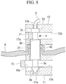
Fig. 8 is a longitudinal cross-sectional view showing a state where the gripping members are made to further swing in the closing direction from the state shown inFig. 7 so that the suture needle penetrates the tissue. - {
Fig. 9 }
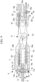
Fig. 9 is a longitudinal cross-sectional view showing a state where the two gripping members are closed from the state shown inFig. 8 so that the suture needle penetrates the tissue, and the holding of the suture needle by the holding members is switched. - {
Fig. 10 }
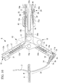
Fig. 10 is a longitudinal cross-sectional view showing a state where the two gripping members are opened again from the state shown inFig. 9 . - {
Fig. 11A }
Fig. 11A is a view for describing a tissue suturing action performed by the suture device according to the embodiment. - {
Fig. 11B }
Fig. 11B is a view for describing the tissue suturing action performed by the suture device according to the embodiment. - {
Fig. 11C }
Fig. 11C is a view for describing the tissue suturing action performed by the suture device according to the embodiment. - {
Fig. 11D }
Fig. 11D is a view for describing the tissue suturing action performed by the suture device according to the embodiment. - {
Fig. 11E }
Fig. 11E is a view for describing the tissue suturing action performed by the suture device according to the embodiment. - {
Fig. 11F }
Fig. 11F is a view for describing the tissue suturing action performed by the suture device according to the embodiment. - {
Fig. 11G }
Fig. 11G is a view for describing the tissue suturing action performed by the suture device according to the embodiment. - {
Fig. 12A }
Fig. 12A is a perspective view showing a relationship between a tubular portion and a projection portion provided on the gripping members of the treatment portion shown inFig. 2 respectively. - {
Fig. 12B }
Fig. 12B is a perspective view of a modification of the tubular portion and the projection portion shown inFig. 12A . - {
Fig. 13A }
Fig. 13A is a longitudinal cross-sectional view showing a state of the projection portion in the modification which is provided on the gripping member of the treatment portion shown inFig. 2 before the projection portion is deformed. - {
Fig. 13B }
Fig. 13B is a longitudinal cross-sectional view showing a state of the projection portion shown inFig. 13A after the projection portion is deformed. - A
suture device 1 according to one embodiment of the present invention is described hereinafter with reference to drawings. - A
suture system 100 in which thesuture device 1 according to this embodiment is used is shown inFig. 1 . - As shown in
Figs. 3 to 4B , thesuture system 100 is a system which sutures tissue A using asuture needle 3 where asuture thread 2 is fixed to one end of thesuture needle 3, and apointed end portion 3a is formed on the other end of thesuture needle 3. As shown inFig. 1 , thesuture system 100 includes an endoscope 4 and thesuture device 1 according to this embodiment. - The endoscope 4 is formed of a known endoscope, and includes a
manipulation portion 6, which is manipulated by an operator, on the proximal end side of an elongatedflexible insertion portion 5. A bendingportion 5a is formed on a distal end portion of theinsertion portion 5, and the bendingportion 5a is bendable by a manipulation of aknob 6a of themanipulation portion 6. - In the
insertion portion 5 of the endoscope 4, twochannels 5b penetrating in the longitudinal direction and opening at the distal end surface are provided. In the drawing, reference symbol "5c" denotes an observation optical system. The number ofchannels 5b may be one or three or more. - The
suture device 1 according to this embodiment includes: a long flexible tubularelongated shaft member 7 having an outer diameter size which allows theelongated shaft member 7 to be inserted into thechannel 5b; atreatment portion 8 provided at a distal end of theelongated shaft member 7; and amanipulation portion 9 provided at a proximal end of theelongated shaft member 7. - As shown in
Fig. 2 , thetreatment portion 8 includes: a base 10 fixed to the distal end of theelongated shaft member 7; and twogripping members elongated shaft member 7. - As shown in
Fig. 3 , each of the twogripping members closing wire 14 via alink 13. With such a configuration, when the opening-closing wire 14 is pulled toward the proximal end side, as shown inFigs. 2 and3 , both grippingmembers members closing wire 14 is pushed out from the proximal end side toward the distal end side, as shown inFig. 5 , both grippingmembers Figs. 3 ,5 ,9 and10 , for the sake of simplification of illustration, thelink 13 which is connected to one grippingmember 11 is indicated by chain lines. - The two
gripping members mechanism 15 for passing thesuture needle 3. - Here, the description is made with respect to the
suture needle 3 which is used in thesuture device 1 according to this embodiment. - As shown in
Figs. 3 to 4B , thesuture needle 3 is formed in a substantially columnar shape. Thesuture needle 3 has the conicalpointed end portion 3a on one end thereof, and thesuture thread 2 is fixed to the other end of thesuture needle 3 by adhesion or the like. On a center portion of thesuture needle 3 in the longitudinal direction, a large-diameter portion 3b having a largest outer diameter size is formed with a predetermined length. Recessedportions 3c are formed on both sides of the large-diameter portion 3b in the longitudinal axis direction respectively at positions where the recessedportions 3c sandwich the large-diameter portion 3b. Each recessedportion 3c is recessed in the radial direction over the whole circumference. Aflange portion 3d and apointed end portion 3a are formed on thesuture needle 3 at positions further toward the end portion sides of thesuture needle 3 from the recessedportions 3c in the axial direction. Theflange portion 3d and thepointed end portion 3a protrude more outside in the radial direction than the recessedportions 3c. - As shown in
Fig. 3 , the passingmechanism 15 is provided with: through holes (fitting hole portions) 11a, 12a formed in the twogripping members members members holes guide holes distal end wires wires members - As shown in
Figs. 4A and 4B , the holdingmembers members portions members members portions 3c of thesuture needle 3. The openingportions members flange portion 3d and thepointed end portion 3a to pass therethrough. - As shown in
Fig. 3 , thedistal end wires drive wires members - The
distal end wires drive wires - The distal ends of the
distal end wires members drive wires manipulation portion 9 on the proximal end side of theelongated shaft member 7. When a tensile force is applied to thedrive wires manipulation portion 9, the tensile force is transmitted to the holdingmembers members distal end wires members - The passing
mechanism 15 also includes aswing member 24 arranged at a position further toward the proximal end side than thepivot 10a of the twogripping members swing member 24 is swingable about aswing axis 24a orthogonal to the longitudinal axis of theelongated shaft member 7. - As shown in
Fig. 3 , theswing member 24 includes a ring-shapedmember 25, and twocolumnar members member 25, and extending parallel to theaxis 24a on both sides of theswing axis 24a with theaxis 24a interposed therebetween. The respectivecolumnar members member 25 such that each of thecolumnar members columnar members holes columnar members columnar members drive wires holes - Opening sizes of the through
holes drive wires members drive wires drive wires members holes columnar members columnar members elongated shaft member 7 so that the ring-shapedmember 25 is made to swing about theswing axis 24a. - At this stage of manipulation, the
columnar members columnar members holes drive wires - As shown in
Fig. 3 , when one of thedrive wires 19b pulls one of thecolumnar members 27 toward the proximal end side so that theswing member 24 is made to swing, theother columnar member 26 is pushed out toward the distal end side, and as a result, the connectingmember 23a on theother drive wire 19a which passes through the throughhole 28 of the pushed-outcolumnar member 26 is caught on the side surface of thecolumnar member 26 thus being pushed out toward the distal end side. When the connectingmember 23a is pushed out, a compressive force in the direction of the otherdistal end wire 18a being pushed out toward the distal end side acts also on the otherdistal end wire 18a connected to theother drive wire 19a by the connectingmember 23a. Thedistal end wire 18a has sufficiently high rigidity so that thedistal end wire 18a transmits the compressive force without buckling whereby the holdingmember 16 at the distal end is pushed out toward the distal end side. Thereby, the holding and releasing of thesuture needle 3 by two holdingmembers - The
suture needle 3 is fitted in the throughholes members suture needle 3 passes through the openingportions members suture needle 3 is disposed in a position where the recessedportions 3c of thesuture needle 3 match with the holdingmembers drive wires members portions portions 3c. - With such operations, since the
flange portion 3d, thepointed end portion 3a and the large-diameter portion 3b are disposed in a position where theflange portion 3d and the large-diameter portion 3b sandwich the recessedportions 3c therebetween and thepointed end portion 3a and the large-diameter portion 3b sandwich the recessedportions 3c therebetween, theflange portion 3d or thepointed end portion 3a and the large-diameter portion 3b engage with the holdingmember 16 or the holdingmember 17 in the longitudinal direction of thesuture needle 3 so that thesuture needle 3 is engaged so as not to move in the longitudinal direction in the throughholes members portions 3c in the radial direction due to tension applied to the holdingmembers suture needle 3 is pressed against the inner surfaces of the throughholes suture needle 3 and the inner surfaces of the throughholes - As shown in
Fig. 2 , anotch 20 is formed on each of the grippingmembers portions members gripping members members holes notches 20 is set larger than the diameter size of thesuture thread 2 so that thesuture thread 2 can be moved in and out of the throughholes notches 20. Thenotches 20 have a shape which is gradually opened toward the outer surface of the grippingmembers suture thread 2 in and out of the throughholes - Further, the
suture device 1 according to this embodiment includes a first cylindrical portion (tubular portion) 30 and a second cylindrical portion (tubular portion) 31 which are formed on the grippingmembers cylindrical portion 30 extends in the axial direction of the throughhole 11a into which thepointed end portion 3a side of thesuture needle 3 is inserted from a surface of the other grippingmember 11 which opposedly facing one of the grippingmembers 12. The secondcylindrical portion 31 extends in the axial direction of the throughhole 12a from a surface of the one of the grippingmembers 12 which opposedly facing the other grippingmember 11. The firstcylindrical portion 30 and the secondcylindrical portion 31 form a contact portion which suppresses the movement of the tissue A in the direction along a surface of the tissue A. - The first
cylindrical portion 30 is disposed in a position where the firstcylindrical portion 30 surrounds substantially the whole circumference of the throughhole 11a. The secondcylindrical portion 31 is disposed in a position where the secondcylindrical portion 31 surrounds substantially the whole circumference of the throughhole 12a. - The term "substantially the whole circumference" is used in the description here because the
gripping members notches 20 and hence, each of the firstcylindrical portion 30 and the secondcylindrical portion 31 is also partially cut in the circumferential direction corresponding to thenotches 20. - The second
cylindrical portion 31 is formed with an inner diameter size larger than an outer diameter size of the firstcylindrical portion 30. - As shown in
Fig. 3 , in a state where the twogripping members cylindrical portion 30 and the secondcylindrical portion 31 are coaxially disposed with a gap therebetween in the radial direction and, at the same time, are disposed such that a distal end portion of the firstcylindrical portion 30 and a distal end portion of the secondcylindrical portion 31 partially overlap with each other in the axial direction. - As shown in
Fig. 1 , themanipulation portion 9 is disposed on the proximal end side of theelongated shaft member 7, and includes an opening-closing manipulation portion 21 for performing an opening-closing action of the twogripping members manipulation portion 22 for pulling the twodrive wires closing manipulation portion 21 includes ahandle 21a formed in the shape of scissor handles, and the opening-closing wire 14 is pushed and pulled in the longitudinal axis direction by an opening-closing manipulation of thehandle 21a. - The operation of the
suture device 1 according to this embodiment having such a configuration are described hereinafter. - In suturing a tissue (suture object) A inside the body using the
suture device 1 according to this embodiment, first, theinsertion portion 5 of the endoscope 4 is inserted into the body and, while the inside of the body is observed using the observationoptical system 5c arranged at a distal end of theinsertion portion 5, the distal end of theinsertion portion 5 is disposed at a position where a portion to be sutured falls within the visual field range of the endoscope 4. - Meanwhile, with respect to the
suture device 1, thehandle 21a of the opening-closing manipulation portion 21 is manipulated so as to close the twogripping members treatment portion 8 as shown inFig. 3 , and thesuture needle 3 is disposed such that thesuture needle 3 passes through the throughholes gripping members handle 22a of the passingmanipulation portion 22, a tensile force is applied to theother drive wire 19b which pulls the holdingmember 17 on theflange portion 3d side of thesuture needle 3 toward the proximal end side. - With such operations, the tensile force is transmitted to the
distal end wire 18b connected to thedrive wire 19b so that the holdingmember 17 is pulled toward the proximal end side, while the connectingmember 23b which connects thedrive wire 19b and thedistal end wire 18b with each other abuts against the side surface of theother columnar member 27 of theswing member 24. As a result, the tensile force of thedrive wire 19b is applied to theother columnar member 27 and that thecolumnar member 27 is pulled toward the proximal end side, so that theswing member 24 is made to swing about theswing axis 24a at such a position thus pushing out one of thecolumnar members 26 toward the distal end side. - With such operations, the tensile force applied to the
other drive wire 19b is transmitted to the other holdingmember 17 via the connectingmember 23b and the otherdistal end wire 18b so that the holdingmember 17 is moved toward the proximal end side, whereby the holdingmember 17 is inserted into the recessedportion 3c on theflange portion 3d side of thesuture needle 3. Together with such operations, the connectingmember 23a mounted on one of thedrive wires 19a is pushed out toward the distal end side by the side surface of thecolumnar member 26 so that the holdingmember 16 is moved toward the distal end side and is brought into a state of releasing thesuture needle 3 on thepointed end portion 3a side. - In such a state, the
suture device 1 according to this embodiment is inserted into thechannel 5b from thetreatment portion 8 side through an insertion port arranged on the proximal end side of theinsertion portion 5 disposed outside the body, and thetreatment portion 8 is made to project from the distal end surface of theinsertion portion 5. With such operations, thetreatment portion 8 is also disposed within the visual field range of the observationoptical system 5c of the endoscope 4. - Then, the tissue A which is a portion to be sutured is disposed in front of the
treatment portion 8 while an endoscope image is observed; with a manipulation of thehandle 21a of the opening-closing manipulation portion 21, the opening-closing wire 14 is pushed toward the distal end side so that the twogripping members links 13 as shown inFigs. 5 and11A so as to dispose the twogripping members member 16 on thepointed end portion 3a side is in a released state of thesuture needle 3, and the holdingmember 17 on theflange portion 3d side is in a fixed state of thesuture needle 3 to the grippingmember 12 and hence, the twogripping members pointed end portion 3a of thesuture needle 3 projects toward the inside. - Next, the
treatment portion 8 is made to advance to a position where the tissue A is sandwiched between the twogripping members closing manipulation portion 21, the opening-closing wire 14 is drawn back toward the proximal end side so as to close the twogripping members links 13. - When the pair of gripping
members Fig. 6 , first, thepointed end portion 3a of thesuture needle 3 is brought into contact with the tissue A. When the pair of grippingmembers Fig. 7 , a portion of the tissue A pressed by thepointed end portion 3a of thesuture needle 3 is pushed into the throughhole 11a of one grippingmember 11. - In such a case, according to the
suture device 1 of this embodiment, in the course of the closing action shown inFig. 6 , the firstcylindrical portion 30 and the secondcylindrical portion 31 are brought into contact with front and back surfaces of the tissue A and sandwich the tissue A. - When the pair of gripping
members cylindrical portion 30 and a distal end of the secondcylindrical portion 31 are gradually firmly pressed against the front and back surfaces of the tissue A so that the movement of the tissue A is restricted by friction. - Accordingly, thereafter, as shown in
Fig. 7 , when the pair of grippingmembers suture needle 3 is further pressed against the tissue A, a tension on the tissue A inside the throughhole 11a is increased and hence, as shown inFig. 8 , the tissue A is easily pierced by thepointed end portion 3a of thesuture needle 3. When the tissue A to which the tension is applied is pierced by thepointed end portion 3a of thesuture needle 3, the tissue A contracts so as to return to its natural shape due to elasticity. - As a result, as shown in
Fig. 9 , thepointed end portion 3a of thesuture needle 3 punctures the tissue A from one side, and is inserted into the throughhole 11a of the other grippingmember 11 disposed on the other side of the tissue A so that the tissue A is sandwiched between the twogripping members - In this case, the first
cylindrical portion 30 and the secondcylindrical portion 31 are disposed in a position where the firstcylindrical portion 30 and the secondcylindrical portion 31 overlap with each other in the axial direction, and both cylindrical portions are disposed with a gap therebetween in the radial direction so that the tissue A sandwiched between both cylindrical portions is maintained in a fine state without being crushed. - In such a state, the
handle 22a of the passingmanipulation portion 22 is manipulated so as to apply a tensile force to thedrive wire 19a which pulls the holdingmember 16 on thepointed end portion 3a side; the tensile force is transmitted to thedrive wire 19a from thehandle 22a so that the holdingmember 16 on thepointed end portion 3a side is pulled, whereby the holdingmember 16 is inserted into the recessedportion 3c on thepointed end portion 3a side as shown inFigs. 9 and11B . At this time, the punctured tissue A contracts to a position where the tissue A does not interfere with the holdingmember 16 and hence, the tissue A will not be sandwiched between the holdingmember 16 and thesuture needle 3. Meanwhile, with swinging of theswing member 24, the holdingmember 17 on theflange portion 3d side is made to advance to release thesuture needle 3. - Then, the
handle 21a of the opening-closing manipulation portion 21 is manipulated again so as to push the opening-closing wire 14 toward the distal end side to open the twogripping members links 13. The holdingmember 17 on theflange portion 3d side has released thesuture needle 3, and the holdingmember 16 on thepointed end portion 3a side fixes thesuture needle 3 to the grippingmember 11, whereby, as shown inFigs. 10 and11C , the twogripping members suture needle 3 projects with theflange portion 3d side of thesuture needle 3 pointing toward the inside. - As a result, the
suture needle 3 passes through a hole H formed in the tissue A so that thesuture thread 2 is made to penetrate the tissue A through the hole H. In such a state, thesuture needle 3 is held by the grippingmember 11 with theflange portion 3d side being made to project, whereby aportion 2b of thesuture thread 2 between the tissue A and theflange portion 3d is inserted into the throughhole 12a of the grippingmember 12 via thenotch 20, and then the twogripping members members suture needle 3 is passed to one of the grippingmembers 12 by the passingmechanism 15. With such operations, as shown inFig. 11D , thesuture needle 3 can be held by the grippingmember 12 again in a state where thepointed end portion 3a side is made to project. - Then, as shown in
Figs. 11E, 11F and11G , a place where thesuture thread 2 is made to penetrate the tissue A is changed, and the procedure described above is repeated so that thesuture thread 2 can be made to penetrate the tissue A at two or more places as shown inFig. 11G . Thereafter, thesuture thread 2 is pulled so that the tissue A can be sutured in a tightly closed state. - As described above, according to the
suture device 1 of this embodiment, in puncturing the tissue A by thesuture needle 3, a tension of the tissue A in a region where thepointed end portion 3a is in contact with the tissue A is increased and hence, even when the tissue A is a soft tissue or the like which is easily stretched, the tissue A can be more reliably pierced so that jamming of the tissue A by the grippingmembers - In this embodiment, the first
cylindrical portion 30 and the secondcylindrical portion 31 shown inFig. 12A are adopted as the tubular portion and the projection portion formed on the pair of grippingmembers - Furthermore, as shown in
Fig. 12B , the secondcylindrical portion 31 may be configured such that the secondcylindrical portion 31 is divided in the circumferential direction, and presses the tissue A at two or more places (four places in the drawing) in the circumferential direction. A shape of the secondcylindrical portion 31 may be an arcuate plate shape as shown inFig. 12B or another shape such as a rod shape. Also in this case, the secondcylindrical portion 31 is required to be disposed so as to press the tissue A at a position outside the firstcylindrical portion 30 in the radial direction, with a gap between the secondcylindrical portion 31 and the firstcylindrical portion 30. - With such a configuration, a tension can be applied to the tissue A between the
cylindrical portions cylindrical portions 31 disposed on both sides of the firstcylindrical portion 30 with the firstcylindrical portion 30 being interposed between the pair of secondcylindrical portions 31 so that the tissue A in the firstcylindrical portion 30 can be easily pierced by thepointed end portion 3a. - The second
cylindrical portion 31 may be formed of an elastic member which can be elastically deformed by pressing the tissue A. With such a configuration, a load applied to the tissue A can be reduced. It is particularly desirable to adopt the secondcylindrical portion 31 having a configuration as shown inFig. 13A , that is, the secondcylindrical portion 31 is formed of an elastic member which is bent such that a ends of the tissue A spreads outward in the radial direction when a distal end of the secondcylindrical portion 31 is further pressed against the tissue A as shown inFig. 13B from a position where the distal end of the secondcylindrical portion 31 is in contact with the tissue A. - With such a configuration, as the second
cylindrical portion 31 is pressed against the tissue A, a frictional force toward the radially outward direction acts so as to increase a tension applied to the tissue A between thecylindrical portions - In this embodiment, the configuration is adopted where when the pair of gripping
members cylindrical portion 30 and the secondcylindrical portion 31 overlap with each other in the axial direction, but an overlap amount thereof may be arbitrarily determined according to a thickness of the tissue A to be sutured. When the tissue A has a large thickness, an overlap amount may be set to a small value or may be set to zero. -
- 1 suture device
- 2 suture thread
- 3 suture needle
- 3a pointed end portion
- 7 elongated shaft member
- 10a pivot
- 11, 12 gripping member
- 11a, 12a through hole (fitting hole portion)
- 15 passing mechanism
- 30 first cylindrical portion (contact portion, tubular portion)
- 31 second cylindrical portion (contact portion, projection portion, elastic member)
- A tissue (suture object)
Claims (6)
- A suture device comprising:an elongated shaft member extending along a longitudinal axis;a pair of two gripping members provided at a distal end of the elongated shaft member in a pivotable manner about a pivot orthogonal to the longitudinal axis so as to be opened and closed relative to each other; anda passing mechanism configured to pass a suture needle between the gripping members, the suture needle to which a suture thread is attached and which has a pointed end portion, whereineach of the gripping members includes: a fitting hole portion which is formed along an opening-closing direction of the gripping members, and to which the suture needle is detachably fitted; and a contact portion which is brought into contact with either of front and back surfaces of a suture object in a course of a closing action of the pair of the gripping members so as to suppress movement of the suture object in a direction along the surface of the suture object.
- The suture device according to claim 1, wherein the contact portion includes: a tubular portion formed so that the tubular portion surrounds a periphery of the fitting hole portion of one of the gripping members provided with the fitting hole portion into which the pointed end portion is inserted and that the tubular portion extends toward the other of the gripping members; and a projection portion, formed at a position where the projection portion surrounds the periphery of the fitting hole portion of the other of the gripping members, and extending toward said one of the gripping members, and
the tubular portion and the projection portion are formed such that the tubular portion and the projection portion are arranged at positions spaced from each other in a radial direction of the fitting hole portions when the two gripping members are completely closed. - The suture device according to claim 2, wherein the tubular portion is formed into a cylindrical shape, and
the projection portion is formed into a cylindrical shape having an inner diameter larger than an outer diameter of the tubular portion. - The suture device according to claim 2, wherein the projection portion is formed of two or more projection portions which are arranged at intervals in a circumferential direction of the fitting hole portion.
- The suture device according to any one of claims 2 to 4, wherein the projection portion is formed of an elastic member which is elastically deformed in contact with the suture object.
- The suture device according to claim 5, wherein the projection portion is elastically deformed such that a distal end of the projection portion is moved in a radially outward direction.
Applications Claiming Priority (2)
| Application Number | Priority Date | Filing Date | Title |
|---|---|---|---|
| JP2015149589 | 2015-07-29 | ||
| PCT/JP2016/061200 WO2017018002A1 (en) | 2015-07-29 | 2016-04-06 | Suturing device |
Publications (3)
| Publication Number | Publication Date |
|---|---|
| EP3332716A1 true EP3332716A1 (en) | 2018-06-13 |
| EP3332716A4 EP3332716A4 (en) | 2019-04-24 |
| EP3332716B1 EP3332716B1 (en) | 2023-08-23 |
Family
ID=57884629
Family Applications (1)
| Application Number | Title | Priority Date | Filing Date |
|---|---|---|---|
| EP16830107.5A Active EP3332716B1 (en) | 2015-07-29 | 2016-04-06 | Suturing device |
Country Status (5)
| Country | Link |
|---|---|
| US (1) | US10729431B2 (en) |
| EP (1) | EP3332716B1 (en) |
| JP (1) | JP6173642B2 (en) |
| CN (1) | CN107530074B (en) |
| WO (1) | WO2017018002A1 (en) |
Families Citing this family (1)
| Publication number | Priority date | Publication date | Assignee | Title |
|---|---|---|---|---|
| WO2025178368A1 (en) * | 2024-02-20 | 2025-08-28 | 주식회사 엔도로보틱스 | Suturing device for endoscopic surgery |
Family Cites Families (11)
| Publication number | Priority date | Publication date | Assignee | Title |
|---|---|---|---|---|
| US1933024A (en) * | 1931-10-06 | 1933-10-31 | Clemens B Nagelmann | Suturing and ligating instrument |
| US7166116B2 (en) | 2003-06-23 | 2007-01-23 | Ethicon, Inc. | Tissue grasper/suture passer instrument |
| DE102004055670A1 (en) | 2004-08-11 | 2006-02-23 | Erbe Elektromedizin Gmbh | Electrosurgical instrument |
| WO2008045376A2 (en) | 2006-10-05 | 2008-04-17 | Tyco Healthcare Group Lp | Axial stitching device |
| WO2008045333A2 (en) | 2006-10-05 | 2008-04-17 | Tyco Healthcare Group Lp | Flexible endoscopic stitching devices |
| US20090204127A1 (en) * | 2008-01-31 | 2009-08-13 | Medicinelodge, Inc. | System and method for tying surgical knots |
| US20100228270A1 (en) | 2008-04-11 | 2010-09-09 | Michael Bogart | Deployment System for Surgical Suture |
| US8864776B2 (en) | 2008-04-11 | 2014-10-21 | Covidien Lp | Deployment system for surgical suture |
| KR101153306B1 (en) * | 2009-10-26 | 2012-06-05 | 국립암센터 | Suturing device for surgery |
| JPWO2013008817A1 (en) * | 2011-07-11 | 2015-02-23 | オリンパスメディカルシステムズ株式会社 | Treatment system and endoscope system |
| JPWO2014030544A1 (en) | 2012-08-24 | 2016-07-28 | オリンパスメディカルシステムズ株式会社 | Suture device |
-
2016
- 2016-04-06 JP JP2017506811A patent/JP6173642B2/en active Active
- 2016-04-06 CN CN201680021172.4A patent/CN107530074B/en active Active
- 2016-04-06 WO PCT/JP2016/061200 patent/WO2017018002A1/en not_active Ceased
- 2016-04-06 EP EP16830107.5A patent/EP3332716B1/en active Active
-
2017
- 2017-11-03 US US15/802,720 patent/US10729431B2/en active Active
Also Published As
| Publication number | Publication date |
|---|---|
| US20180064436A1 (en) | 2018-03-08 |
| JP6173642B2 (en) | 2017-08-02 |
| CN107530074A (en) | 2018-01-02 |
| WO2017018002A1 (en) | 2017-02-02 |
| EP3332716A4 (en) | 2019-04-24 |
| CN107530074B (en) | 2020-03-27 |
| EP3332716B1 (en) | 2023-08-23 |
| US10729431B2 (en) | 2020-08-04 |
| JPWO2017018002A1 (en) | 2017-07-27 |
Similar Documents
| Publication | Publication Date | Title |
|---|---|---|
| US9775603B2 (en) | Suture instrument | |
| EP1929960B1 (en) | Perforation suture clip and clip device | |
| US20160317155A1 (en) | Atrial-appendage ligation treatment tool and atrial-appendage ligation system | |
| EP1584295B1 (en) | Ligature and suture device for medical application | |
| CN105050512B (en) | Line drive | |
| JP5815109B2 (en) | Suture device | |
| CN106456174A (en) | Surgical instrument | |
| WO2013073523A1 (en) | Medical instrument | |
| US9693769B2 (en) | Suture device | |
| WO2019097560A1 (en) | Medical grasper | |
| US20160310155A1 (en) | Atrial-appendage ligation surgical tool and atrial appendage ligation system | |
| US10729431B2 (en) | Suture device | |
| EP3272296A1 (en) | Suturing device | |
| CN111867488B (en) | Needle holder and method of use | |
| JPWO2016067436A1 (en) | Medical treatment tool | |
| JPH01129843A (en) | Suturing forceps | |
| US10729425B2 (en) | Suture device | |
| EP3520717B1 (en) | Clip removal device | |
| JP6400420B2 (en) | Bone fixation forceps | |
| EP1832237A1 (en) | Ligature and suture device for medical application |
Legal Events
| Date | Code | Title | Description |
|---|---|---|---|
| STAA | Information on the status of an ep patent application or granted ep patent |
Free format text: STATUS: THE INTERNATIONAL PUBLICATION HAS BEEN MADE |
|
| PUAI | Public reference made under article 153(3) epc to a published international application that has entered the european phase |
Free format text: ORIGINAL CODE: 0009012 |
|
| STAA | Information on the status of an ep patent application or granted ep patent |
Free format text: STATUS: REQUEST FOR EXAMINATION WAS MADE |
|
| 17P | Request for examination filed |
Effective date: 20180227 |
|
| AK | Designated contracting states |
Kind code of ref document: A1 Designated state(s): AL AT BE BG CH CY CZ DE DK EE ES FI FR GB GR HR HU IE IS IT LI LT LU LV MC MK MT NL NO PL PT RO RS SE SI SK SM TR |
|
| AX | Request for extension of the european patent |
Extension state: BA ME |
|
| DAV | Request for validation of the european patent (deleted) | ||
| DAX | Request for extension of the european patent (deleted) | ||
| A4 | Supplementary search report drawn up and despatched |
Effective date: 20190322 |
|
| RIC1 | Information provided on ipc code assigned before grant |
Ipc: A61B 17/062 20060101AFI20190318BHEP |
|
| GRAP | Despatch of communication of intention to grant a patent |
Free format text: ORIGINAL CODE: EPIDOSNIGR1 |
|
| STAA | Information on the status of an ep patent application or granted ep patent |
Free format text: STATUS: GRANT OF PATENT IS INTENDED |
|
| RIC1 | Information provided on ipc code assigned before grant |
Ipc: A61B 17/00 20060101ALN20230217BHEP Ipc: A61B 17/04 20060101ALI20230217BHEP Ipc: A61B 17/062 20060101AFI20230217BHEP |
|
| INTG | Intention to grant announced |
Effective date: 20230315 |
|
| P01 | Opt-out of the competence of the unified patent court (upc) registered |
Effective date: 20230528 |
|
| GRAS | Grant fee paid |
Free format text: ORIGINAL CODE: EPIDOSNIGR3 |
|
| GRAA | (expected) grant |
Free format text: ORIGINAL CODE: 0009210 |
|
| STAA | Information on the status of an ep patent application or granted ep patent |
Free format text: STATUS: THE PATENT HAS BEEN GRANTED |
|
| AK | Designated contracting states |
Kind code of ref document: B1 Designated state(s): AL AT BE BG CH CY CZ DE DK EE ES FI FR GB GR HR HU IE IS IT LI LT LU LV MC MK MT NL NO PL PT RO RS SE SI SK SM TR |
|
| REG | Reference to a national code |
Ref country code: GB Ref legal event code: FG4D |
|
| REG | Reference to a national code |
Ref country code: CH Ref legal event code: EP |
|
| REG | Reference to a national code |
Ref country code: IE Ref legal event code: FG4D |
|
| REG | Reference to a national code |
Ref country code: DE Ref legal event code: R096 Ref document number: 602016082175 Country of ref document: DE |
|
| REG | Reference to a national code |
Ref country code: LT Ref legal event code: MG9D |
|
| REG | Reference to a national code |
Ref country code: NL Ref legal event code: MP Effective date: 20230823 |
|
| REG | Reference to a national code |
Ref country code: AT Ref legal event code: MK05 Ref document number: 1601635 Country of ref document: AT Kind code of ref document: T Effective date: 20230823 |
|
| PG25 | Lapsed in a contracting state [announced via postgrant information from national office to epo] |
Ref country code: GR Free format text: LAPSE BECAUSE OF FAILURE TO SUBMIT A TRANSLATION OF THE DESCRIPTION OR TO PAY THE FEE WITHIN THE PRESCRIBED TIME-LIMIT Effective date: 20231124 |
|
| PG25 | Lapsed in a contracting state [announced via postgrant information from national office to epo] |
Ref country code: IS Free format text: LAPSE BECAUSE OF FAILURE TO SUBMIT A TRANSLATION OF THE DESCRIPTION OR TO PAY THE FEE WITHIN THE PRESCRIBED TIME-LIMIT Effective date: 20231223 |
|
| PG25 | Lapsed in a contracting state [announced via postgrant information from national office to epo] |
Ref country code: SE Free format text: LAPSE BECAUSE OF FAILURE TO SUBMIT A TRANSLATION OF THE DESCRIPTION OR TO PAY THE FEE WITHIN THE PRESCRIBED TIME-LIMIT Effective date: 20230823 Ref country code: RS Free format text: LAPSE BECAUSE OF FAILURE TO SUBMIT A TRANSLATION OF THE DESCRIPTION OR TO PAY THE FEE WITHIN THE PRESCRIBED TIME-LIMIT Effective date: 20230823 Ref country code: PT Free format text: LAPSE BECAUSE OF FAILURE TO SUBMIT A TRANSLATION OF THE DESCRIPTION OR TO PAY THE FEE WITHIN THE PRESCRIBED TIME-LIMIT Effective date: 20231226 Ref country code: NO Free format text: LAPSE BECAUSE OF FAILURE TO SUBMIT A TRANSLATION OF THE DESCRIPTION OR TO PAY THE FEE WITHIN THE PRESCRIBED TIME-LIMIT Effective date: 20231123 Ref country code: NL Free format text: LAPSE BECAUSE OF FAILURE TO SUBMIT A TRANSLATION OF THE DESCRIPTION OR TO PAY THE FEE WITHIN THE PRESCRIBED TIME-LIMIT Effective date: 20230823 Ref country code: LV Free format text: LAPSE BECAUSE OF FAILURE TO SUBMIT A TRANSLATION OF THE DESCRIPTION OR TO PAY THE FEE WITHIN THE PRESCRIBED TIME-LIMIT Effective date: 20230823 Ref country code: LT Free format text: LAPSE BECAUSE OF FAILURE TO SUBMIT A TRANSLATION OF THE DESCRIPTION OR TO PAY THE FEE WITHIN THE PRESCRIBED TIME-LIMIT Effective date: 20230823 Ref country code: IS Free format text: LAPSE BECAUSE OF FAILURE TO SUBMIT A TRANSLATION OF THE DESCRIPTION OR TO PAY THE FEE WITHIN THE PRESCRIBED TIME-LIMIT Effective date: 20231223 Ref country code: HR Free format text: LAPSE BECAUSE OF FAILURE TO SUBMIT A TRANSLATION OF THE DESCRIPTION OR TO PAY THE FEE WITHIN THE PRESCRIBED TIME-LIMIT Effective date: 20230823 Ref country code: GR Free format text: LAPSE BECAUSE OF FAILURE TO SUBMIT A TRANSLATION OF THE DESCRIPTION OR TO PAY THE FEE WITHIN THE PRESCRIBED TIME-LIMIT Effective date: 20231124 Ref country code: FI Free format text: LAPSE BECAUSE OF FAILURE TO SUBMIT A TRANSLATION OF THE DESCRIPTION OR TO PAY THE FEE WITHIN THE PRESCRIBED TIME-LIMIT Effective date: 20230823 Ref country code: AT Free format text: LAPSE BECAUSE OF FAILURE TO SUBMIT A TRANSLATION OF THE DESCRIPTION OR TO PAY THE FEE WITHIN THE PRESCRIBED TIME-LIMIT Effective date: 20230823 |
|
| PG25 | Lapsed in a contracting state [announced via postgrant information from national office to epo] |
Ref country code: PL Free format text: LAPSE BECAUSE OF FAILURE TO SUBMIT A TRANSLATION OF THE DESCRIPTION OR TO PAY THE FEE WITHIN THE PRESCRIBED TIME-LIMIT Effective date: 20230823 |
|
| PG25 | Lapsed in a contracting state [announced via postgrant information from national office to epo] |
Ref country code: ES Free format text: LAPSE BECAUSE OF FAILURE TO SUBMIT A TRANSLATION OF THE DESCRIPTION OR TO PAY THE FEE WITHIN THE PRESCRIBED TIME-LIMIT Effective date: 20230823 |
|
| PG25 | Lapsed in a contracting state [announced via postgrant information from national office to epo] |
Ref country code: SM Free format text: LAPSE BECAUSE OF FAILURE TO SUBMIT A TRANSLATION OF THE DESCRIPTION OR TO PAY THE FEE WITHIN THE PRESCRIBED TIME-LIMIT Effective date: 20230823 Ref country code: RO Free format text: LAPSE BECAUSE OF FAILURE TO SUBMIT A TRANSLATION OF THE DESCRIPTION OR TO PAY THE FEE WITHIN THE PRESCRIBED TIME-LIMIT Effective date: 20230823 Ref country code: ES Free format text: LAPSE BECAUSE OF FAILURE TO SUBMIT A TRANSLATION OF THE DESCRIPTION OR TO PAY THE FEE WITHIN THE PRESCRIBED TIME-LIMIT Effective date: 20230823 Ref country code: EE Free format text: LAPSE BECAUSE OF FAILURE TO SUBMIT A TRANSLATION OF THE DESCRIPTION OR TO PAY THE FEE WITHIN THE PRESCRIBED TIME-LIMIT Effective date: 20230823 Ref country code: DK Free format text: LAPSE BECAUSE OF FAILURE TO SUBMIT A TRANSLATION OF THE DESCRIPTION OR TO PAY THE FEE WITHIN THE PRESCRIBED TIME-LIMIT Effective date: 20230823 Ref country code: CZ Free format text: LAPSE BECAUSE OF FAILURE TO SUBMIT A TRANSLATION OF THE DESCRIPTION OR TO PAY THE FEE WITHIN THE PRESCRIBED TIME-LIMIT Effective date: 20230823 Ref country code: SK Free format text: LAPSE BECAUSE OF FAILURE TO SUBMIT A TRANSLATION OF THE DESCRIPTION OR TO PAY THE FEE WITHIN THE PRESCRIBED TIME-LIMIT Effective date: 20230823 |
|
| REG | Reference to a national code |
Ref country code: DE Ref legal event code: R097 Ref document number: 602016082175 Country of ref document: DE |
|
| PG25 | Lapsed in a contracting state [announced via postgrant information from national office to epo] |
Ref country code: IT Free format text: LAPSE BECAUSE OF FAILURE TO SUBMIT A TRANSLATION OF THE DESCRIPTION OR TO PAY THE FEE WITHIN THE PRESCRIBED TIME-LIMIT Effective date: 20230823 |
|
| PLBE | No opposition filed within time limit |
Free format text: ORIGINAL CODE: 0009261 |
|
| STAA | Information on the status of an ep patent application or granted ep patent |
Free format text: STATUS: NO OPPOSITION FILED WITHIN TIME LIMIT |
|
| 26N | No opposition filed |
Effective date: 20240524 |
|
| PG25 | Lapsed in a contracting state [announced via postgrant information from national office to epo] |
Ref country code: SI Free format text: LAPSE BECAUSE OF FAILURE TO SUBMIT A TRANSLATION OF THE DESCRIPTION OR TO PAY THE FEE WITHIN THE PRESCRIBED TIME-LIMIT Effective date: 20230823 |
|
| PG25 | Lapsed in a contracting state [announced via postgrant information from national office to epo] |
Ref country code: BG Free format text: LAPSE BECAUSE OF FAILURE TO SUBMIT A TRANSLATION OF THE DESCRIPTION OR TO PAY THE FEE WITHIN THE PRESCRIBED TIME-LIMIT Effective date: 20230823 |
|
| PG25 | Lapsed in a contracting state [announced via postgrant information from national office to epo] |
Ref country code: MC Free format text: LAPSE BECAUSE OF FAILURE TO SUBMIT A TRANSLATION OF THE DESCRIPTION OR TO PAY THE FEE WITHIN THE PRESCRIBED TIME-LIMIT Effective date: 20230823 |
|
| PG25 | Lapsed in a contracting state [announced via postgrant information from national office to epo] |
Ref country code: MC Free format text: LAPSE BECAUSE OF FAILURE TO SUBMIT A TRANSLATION OF THE DESCRIPTION OR TO PAY THE FEE WITHIN THE PRESCRIBED TIME-LIMIT Effective date: 20230823 Ref country code: BG Free format text: LAPSE BECAUSE OF FAILURE TO SUBMIT A TRANSLATION OF THE DESCRIPTION OR TO PAY THE FEE WITHIN THE PRESCRIBED TIME-LIMIT Effective date: 20230823 |
|
| REG | Reference to a national code |
Ref country code: CH Ref legal event code: PL |
|
| PG25 | Lapsed in a contracting state [announced via postgrant information from national office to epo] |
Ref country code: LU Free format text: LAPSE BECAUSE OF NON-PAYMENT OF DUE FEES Effective date: 20240406 |
|
| GBPC | Gb: european patent ceased through non-payment of renewal fee |
Effective date: 20240406 |
|
| REG | Reference to a national code |
Ref country code: BE Ref legal event code: MM Effective date: 20240430 |
|
| PG25 | Lapsed in a contracting state [announced via postgrant information from national office to epo] |
Ref country code: LU Free format text: LAPSE BECAUSE OF NON-PAYMENT OF DUE FEES Effective date: 20240406 |
|
| PG25 | Lapsed in a contracting state [announced via postgrant information from national office to epo] |
Ref country code: BE Free format text: LAPSE BECAUSE OF NON-PAYMENT OF DUE FEES Effective date: 20240430 |
|
| PG25 | Lapsed in a contracting state [announced via postgrant information from national office to epo] |
Ref country code: GB Free format text: LAPSE BECAUSE OF NON-PAYMENT OF DUE FEES Effective date: 20240406 |
|
| PG25 | Lapsed in a contracting state [announced via postgrant information from national office to epo] |
Ref country code: FR Free format text: LAPSE BECAUSE OF NON-PAYMENT OF DUE FEES Effective date: 20240430 |
|
| PG25 | Lapsed in a contracting state [announced via postgrant information from national office to epo] |
Ref country code: GB Free format text: LAPSE BECAUSE OF NON-PAYMENT OF DUE FEES Effective date: 20240406 Ref country code: FR Free format text: LAPSE BECAUSE OF NON-PAYMENT OF DUE FEES Effective date: 20240430 Ref country code: BE Free format text: LAPSE BECAUSE OF NON-PAYMENT OF DUE FEES Effective date: 20240430 Ref country code: CH Free format text: LAPSE BECAUSE OF NON-PAYMENT OF DUE FEES Effective date: 20240430 |
|
| PG25 | Lapsed in a contracting state [announced via postgrant information from national office to epo] |
Ref country code: IE Free format text: LAPSE BECAUSE OF NON-PAYMENT OF DUE FEES Effective date: 20240406 |
|
| PGFP | Annual fee paid to national office [announced via postgrant information from national office to epo] |
Ref country code: DE Payment date: 20250422 Year of fee payment: 10 |
|
| PG25 | Lapsed in a contracting state [announced via postgrant information from national office to epo] |
Ref country code: CY Free format text: LAPSE BECAUSE OF FAILURE TO SUBMIT A TRANSLATION OF THE DESCRIPTION OR TO PAY THE FEE WITHIN THE PRESCRIBED TIME-LIMIT; INVALID AB INITIO Effective date: 20160406 |
|
| PG25 | Lapsed in a contracting state [announced via postgrant information from national office to epo] |
Ref country code: HU Free format text: LAPSE BECAUSE OF FAILURE TO SUBMIT A TRANSLATION OF THE DESCRIPTION OR TO PAY THE FEE WITHIN THE PRESCRIBED TIME-LIMIT; INVALID AB INITIO Effective date: 20160406 |
|
| PG25 | Lapsed in a contracting state [announced via postgrant information from national office to epo] |
Ref country code: TR Free format text: LAPSE BECAUSE OF FAILURE TO SUBMIT A TRANSLATION OF THE DESCRIPTION OR TO PAY THE FEE WITHIN THE PRESCRIBED TIME-LIMIT Effective date: 20230823 |