EP3332709A1 - Computerized tomography image correction - Google Patents
Computerized tomography image correction Download PDFInfo
- Publication number
- EP3332709A1 EP3332709A1 EP17203897.8A EP17203897A EP3332709A1 EP 3332709 A1 EP3332709 A1 EP 3332709A1 EP 17203897 A EP17203897 A EP 17203897A EP 3332709 A1 EP3332709 A1 EP 3332709A1
- Authority
- EP
- European Patent Office
- Prior art keywords
- coordinate system
- image
- dimensional image
- voxels
- open space
- Prior art date
- Legal status (The legal status is an assumption and is not a legal conclusion. Google has not performed a legal analysis and makes no representation as to the accuracy of the status listed.)
- Granted
Links
Images


Classifications
-
- A—HUMAN NECESSITIES
- A61—MEDICAL OR VETERINARY SCIENCE; HYGIENE
- A61B—DIAGNOSIS; SURGERY; IDENTIFICATION
- A61B5/00—Measuring for diagnostic purposes; Identification of persons
- A61B5/06—Devices, other than using radiation, for detecting or locating foreign bodies ; Determining position of diagnostic devices within or on the body of the patient
- A61B5/065—Determining position of the probe employing exclusively positioning means located on or in the probe, e.g. using position sensors arranged on the probe
- A61B5/066—Superposing sensor position on an image of the patient, e.g. obtained by ultrasound or x-ray imaging
-
- A—HUMAN NECESSITIES
- A61—MEDICAL OR VETERINARY SCIENCE; HYGIENE
- A61B—DIAGNOSIS; SURGERY; IDENTIFICATION
- A61B5/00—Measuring for diagnostic purposes; Identification of persons
- A61B5/06—Devices, other than using radiation, for detecting or locating foreign bodies ; Determining position of diagnostic devices within or on the body of the patient
- A61B5/061—Determining position of a probe within the body employing means separate from the probe, e.g. sensing internal probe position employing impedance electrodes on the surface of the body
- A61B5/062—Determining position of a probe within the body employing means separate from the probe, e.g. sensing internal probe position employing impedance electrodes on the surface of the body using magnetic field
-
- A—HUMAN NECESSITIES
- A61—MEDICAL OR VETERINARY SCIENCE; HYGIENE
- A61B—DIAGNOSIS; SURGERY; IDENTIFICATION
- A61B6/00—Apparatus or devices for radiation diagnosis; Apparatus or devices for radiation diagnosis combined with radiation therapy equipment
- A61B6/02—Arrangements for diagnosis sequentially in different planes; Stereoscopic radiation diagnosis
- A61B6/03—Computed tomography [CT]
-
- A—HUMAN NECESSITIES
- A61—MEDICAL OR VETERINARY SCIENCE; HYGIENE
- A61B—DIAGNOSIS; SURGERY; IDENTIFICATION
- A61B6/00—Apparatus or devices for radiation diagnosis; Apparatus or devices for radiation diagnosis combined with radiation therapy equipment
- A61B6/46—Arrangements for interfacing with the operator or the patient
- A61B6/461—Displaying means of special interest
- A61B6/466—Displaying means of special interest adapted to display 3D data
-
- A—HUMAN NECESSITIES
- A61—MEDICAL OR VETERINARY SCIENCE; HYGIENE
- A61B—DIAGNOSIS; SURGERY; IDENTIFICATION
- A61B6/00—Apparatus or devices for radiation diagnosis; Apparatus or devices for radiation diagnosis combined with radiation therapy equipment
- A61B6/52—Devices using data or image processing specially adapted for radiation diagnosis
-
- A—HUMAN NECESSITIES
- A61—MEDICAL OR VETERINARY SCIENCE; HYGIENE
- A61B—DIAGNOSIS; SURGERY; IDENTIFICATION
- A61B6/00—Apparatus or devices for radiation diagnosis; Apparatus or devices for radiation diagnosis combined with radiation therapy equipment
- A61B6/52—Devices using data or image processing specially adapted for radiation diagnosis
- A61B6/5211—Devices using data or image processing specially adapted for radiation diagnosis involving processing of medical diagnostic data
- A61B6/5229—Devices using data or image processing specially adapted for radiation diagnosis involving processing of medical diagnostic data combining image data of a patient, e.g. combining a functional image with an anatomical image
- A61B6/5247—Devices using data or image processing specially adapted for radiation diagnosis involving processing of medical diagnostic data combining image data of a patient, e.g. combining a functional image with an anatomical image combining images from an ionising-radiation diagnostic technique and a non-ionising radiation diagnostic technique, e.g. X-ray and ultrasound
-
- A—HUMAN NECESSITIES
- A61—MEDICAL OR VETERINARY SCIENCE; HYGIENE
- A61B—DIAGNOSIS; SURGERY; IDENTIFICATION
- A61B6/00—Apparatus or devices for radiation diagnosis; Apparatus or devices for radiation diagnosis combined with radiation therapy equipment
- A61B6/52—Devices using data or image processing specially adapted for radiation diagnosis
- A61B6/5258—Devices using data or image processing specially adapted for radiation diagnosis involving detection or reduction of artifacts or noise
-
- A—HUMAN NECESSITIES
- A61—MEDICAL OR VETERINARY SCIENCE; HYGIENE
- A61B—DIAGNOSIS; SURGERY; IDENTIFICATION
- A61B6/00—Apparatus or devices for radiation diagnosis; Apparatus or devices for radiation diagnosis combined with radiation therapy equipment
- A61B6/58—Testing, adjusting or calibrating thereof
- A61B6/582—Calibration
-
- G—PHYSICS
- G06—COMPUTING OR CALCULATING; COUNTING
- G06T—IMAGE DATA PROCESSING OR GENERATION, IN GENERAL
- G06T17/00—Three-dimensional [3D] modelling for computer graphics
- G06T17/20—Finite element generation, e.g. wire-frame surface description, tesselation
-
- G—PHYSICS
- G06—COMPUTING OR CALCULATING; COUNTING
- G06T—IMAGE DATA PROCESSING OR GENERATION, IN GENERAL
- G06T7/00—Image analysis
- G06T7/0002—Inspection of images, e.g. flaw detection
- G06T7/0012—Biomedical image inspection
-
- A—HUMAN NECESSITIES
- A61—MEDICAL OR VETERINARY SCIENCE; HYGIENE
- A61B—DIAGNOSIS; SURGERY; IDENTIFICATION
- A61B17/00—Surgical instruments, devices or methods
- A61B17/24—Surgical instruments, devices or methods for use in the oral cavity, larynx, bronchial passages or nose; Tongue scrapers
-
- A—HUMAN NECESSITIES
- A61—MEDICAL OR VETERINARY SCIENCE; HYGIENE
- A61B—DIAGNOSIS; SURGERY; IDENTIFICATION
- A61B17/00—Surgical instruments, devices or methods
- A61B17/32—Surgical cutting instruments
- A61B17/320016—Endoscopic cutting instruments, e.g. arthroscopes, resectoscopes
- A61B17/32002—Endoscopic cutting instruments, e.g. arthroscopes, resectoscopes with continuously rotating, oscillating or reciprocating cutting instruments
-
- A—HUMAN NECESSITIES
- A61—MEDICAL OR VETERINARY SCIENCE; HYGIENE
- A61B—DIAGNOSIS; SURGERY; IDENTIFICATION
- A61B34/00—Computer-aided surgery; Manipulators or robots specially adapted for use in surgery
- A61B34/20—Surgical navigation systems; Devices for tracking or guiding surgical instruments, e.g. for frameless stereotaxis
- A61B2034/2046—Tracking techniques
- A61B2034/2051—Electromagnetic tracking systems
-
- A—HUMAN NECESSITIES
- A61—MEDICAL OR VETERINARY SCIENCE; HYGIENE
- A61B—DIAGNOSIS; SURGERY; IDENTIFICATION
- A61B34/00—Computer-aided surgery; Manipulators or robots specially adapted for use in surgery
- A61B34/20—Surgical navigation systems; Devices for tracking or guiding surgical instruments, e.g. for frameless stereotaxis
- A61B2034/2072—Reference field transducer attached to an instrument or patient
-
- A—HUMAN NECESSITIES
- A61—MEDICAL OR VETERINARY SCIENCE; HYGIENE
- A61B—DIAGNOSIS; SURGERY; IDENTIFICATION
- A61B90/00—Instruments, implements or accessories specially adapted for surgery or diagnosis and not covered by any of the groups A61B1/00 - A61B50/00, e.g. for luxation treatment or for protecting wound edges
- A61B90/36—Image-producing devices or illumination devices not otherwise provided for
- A61B2090/364—Correlation of different images or relation of image positions in respect to the body
- A61B2090/367—Correlation of different images or relation of image positions in respect to the body creating a 3D dataset from 2D images using position information
-
- A—HUMAN NECESSITIES
- A61—MEDICAL OR VETERINARY SCIENCE; HYGIENE
- A61B—DIAGNOSIS; SURGERY; IDENTIFICATION
- A61B90/00—Instruments, implements or accessories specially adapted for surgery or diagnosis and not covered by any of the groups A61B1/00 - A61B50/00, e.g. for luxation treatment or for protecting wound edges
- A61B90/36—Image-producing devices or illumination devices not otherwise provided for
- A61B90/37—Surgical systems with images on a monitor during operation
- A61B2090/376—Surgical systems with images on a monitor during operation using X-rays, e.g. fluoroscopy
- A61B2090/3762—Surgical systems with images on a monitor during operation using X-rays, e.g. fluoroscopy using computed tomography systems [CT]
-
- A—HUMAN NECESSITIES
- A61—MEDICAL OR VETERINARY SCIENCE; HYGIENE
- A61B—DIAGNOSIS; SURGERY; IDENTIFICATION
- A61B34/00—Computer-aided surgery; Manipulators or robots specially adapted for use in surgery
- A61B34/20—Surgical navigation systems; Devices for tracking or guiding surgical instruments, e.g. for frameless stereotaxis
-
- A—HUMAN NECESSITIES
- A61—MEDICAL OR VETERINARY SCIENCE; HYGIENE
- A61B—DIAGNOSIS; SURGERY; IDENTIFICATION
- A61B6/00—Apparatus or devices for radiation diagnosis; Apparatus or devices for radiation diagnosis combined with radiation therapy equipment
- A61B6/02—Arrangements for diagnosis sequentially in different planes; Stereoscopic radiation diagnosis
- A61B6/03—Computed tomography [CT]
- A61B6/032—Transmission computed tomography [CT]
-
- G—PHYSICS
- G06—COMPUTING OR CALCULATING; COUNTING
- G06T—IMAGE DATA PROCESSING OR GENERATION, IN GENERAL
- G06T2207/00—Indexing scheme for image analysis or image enhancement
- G06T2207/10—Image acquisition modality
- G06T2207/10072—Tomographic images
- G06T2207/10081—Computed x-ray tomography [CT]
-
- G—PHYSICS
- G06—COMPUTING OR CALCULATING; COUNTING
- G06T—IMAGE DATA PROCESSING OR GENERATION, IN GENERAL
- G06T2210/00—Indexing scheme for image generation or computer graphics
- G06T2210/41—Medical
Definitions
- the present invention relates generally to medical imaging, and specifically to correcting a compromised computerized tomography image while performing an invasive medical procedure.
- a real-time representation of a medical device such as a catheter tracked by a medical imaging system (e.g., a computed tomography scanner) during a medical procedure
- a medical imaging system e.g., a computed tomography scanner
- An image that was previously acquired from a medical imaging system can be used to generate a real-time guide (i.e., a "map") that enables an operator performing the medical procedure to navigate the medical device within a volume of interest in a body of a patient.
- a real-time guide i.e., a "map”
- it is typically required to register the coordinate system associated with the medical device with the coordinate system associated with the medical imaging system.
- a method including receiving, from an imaging system operating in an image coordinate system, a three-dimensional image of a body cavity including open space and body tissue, receiving, from a medical probe having a location sensor and inserted into the body cavity, a signal indicating a location of a distal tip of the medical probe in a sensor coordinate system, registering, by a processor, the image coordinate system with the sensor coordinate system so as to identify one or more voxels in the three-dimensional image at the indicated location, and when the identified voxels have density values in the received three-dimensional image that do not correspond to the open space, updating the density values of the identified voxels to correspond to the open space.
- the imaging system includes a computed tomography scanner.
- the location sensor includes a magnetic field sensor.
- the method may include forming a correspondence between the density values and visual effects, wherein a given visual effect corresponds to a given density value indicating the open space.
- the visual effects may be selected from a group consisting of colors, shadings and patterns.
- the method may include, presenting the three-dimensional image on a display using the visual effects.
- the given visual effect includes a first given visual effect
- presenting the three-dimensional image includes presenting, using a second given visual effect different from the first given visual effect, the one or more identified voxels.
- presenting the three-dimensional image may include presenting, using the first given visual effect, the one or more identified voxels.
- an apparatus including a medical probe configured to be inserted into a body cavity, a location sensor in the medical probe operating in a sensor coordinate system, and a processor configured to receive, from an imaging system operating in an image coordinate system, a three-dimensional image of the body cavity including open space and body tissue, to receive, from the medical probe, a signal indicating a location of a distal tip of the medical probe, to register the image coordinate system with the sensor coordinate system so as to identify one or more voxels in the three-dimensional image at the indicated location, and when the identified voxels have density values in the received three-dimensional image that do not correspond to the open space, to update the density values of the identified voxels to correspond to the open space.
- a computer software product operated in conjunction with a probe that is configured for insertion into a body cavity of a patient and includes a location sensor operating in a sensor coordinate system, the product including a non-transitory computer-readable medium, in which program instructions are stored, which instructions, when read by a computer, cause the computer to receive, from an imaging system operating in an image coordinate system, a three-dimensional image of the body cavity including open space and body tissue, to receive, from the medical probe, a signal indicating a location of a distal tip of the medical probe, to register the image coordinate system with the sensor coordinate system so as to identify one or more voxels in the three-dimensional image at the indicated location, and when the identified voxels have density values in the received three-dimensional image that do not correspond to the open space, to update the density values of the identified voxels to correspond to the open space.
- Medical images used during medical procedures on a body cavity may sometimes be compromised.
- computerized tomography images from a computerized tomography scanner can be compromised due to factors such as incorrect settings of the scanner, patient movement, and dental work in proximity to the body cavity.
- the compromisation is typically presented as noise or clutter on the image.
- Embodiments of the present invention provide methods and systems for correcting a compromised medical image such as a computed tomography image, also referred to herein as a three-dimensional image.
- a three-dimensional image of a body cavity comprising open space and body tissue is received from an imaging system operating in an image coordinate system, and a signal is received from a medical probe having a location sensor and inserted into the body cavity, the signal indicating a location of a distal tip of the medical probe in a sensor coordinate system.
- the image coordinate system is registered with the sensor coordinate system so as to identify one or more voxels in the three-dimensional image at the indicated location, and when the identified voxels have density values in the received three-dimensional image that do not correspond to the open space, the density values of the identified voxels are updated to correspond to the open space.
- a computed tomography system may present open space in black, hard body tissue in white and soft body tissue in (various shades of) gray. Since the distal tip of the medical probe can only be inserted into open space, systems implementing embodiments of the present invention can correct, on the three-dimensional image, any locations of the distal tip that are not presented as open space.
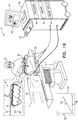
- Figures 1A and 1B are schematic pictorial illustrations of a medical system 20 configured to correct a compromised computerized tomography image while performing an invasive medical procedure, in accordance with an embodiment of the present invention.
- medical system 20 comprises a medical imaging system comprising a computed tomography scanner 22, and control console 24, and a medical probe 36.
- medical probe 36 is used for diagnostic or therapeutic treatment, such as minimally invasive catheter-based sinus surgery on a patient 26.
- medical probe 36 may be used, mutatis mutandis, for other therapeutic and/or diagnostic purposes.
- computed tomography scanner 22 prior to performing an invasive medical procedure on patient 26, computed tomography scanner 22 generates electrical signals comprising image data for a lumen (e.g., a nasal cavity or a paranasal sinus) of the patient, and conveys the generated image data to control console 24.
- Computed tomography scanner 22 generates the image data in an image coordinate system 28 comprising an X-axis 30, a Y-axis 32 and a Z-axis 34.
- medical probe 36 comprises a handle 38 that an operator 40 can grasp and manipulate in order to insert a distal end 42 of the medical probe into a lumen, such as a nasal cavity or a paranasal sinus, of patient 26.
- control console 24 comprises a processor 44 that converts the received image data into an image 46, and presents the image as information regarding the medical procedure on a display 48.
- Display 48 is assumed, by way of example, to comprise a flat panel display such as a liquid crystal display, a light emitting diode display, an organic light-emitting diode display or a plasma display. However, other display devices can also be employed to implement embodiments of the present invention. In some embodiments, display 48 may comprise a touchscreen that can be configured to accept inputs from operator 40, in addition to presenting image 46.
- a flat panel display such as a liquid crystal display, a light emitting diode display, an organic light-emitting diode display or a plasma display.
- display 48 may comprise a touchscreen that can be configured to accept inputs from operator 40, in addition to presenting image 46.
- control console 24 drives display 48 to update image 46 in order to present a current position of distal end 42 in the patient's body, as well as status information and guidance regarding the medical procedure that is in progress.
- Processor 44 stores data representing image 46 in a memory 50.
- operator 40 can manipulate image 46 using one or more input devices 52.
- display 48 comprises a touchscreen display
- operator 40 can manipulate image 46 via the touchscreen display.
- Processor 44 typically comprises a general-purpose computer, with suitable front end and interface circuits for receiving signals from medical probe 36 and controlling the other components of control console 24.
- Processor 44 may be programmed in software to carry out the functions that are described herein.
- the software may be downloaded to control console 24 in electronic form, over a network, for example, or it may be provided on non-transitory tangible media, such as optical, magnetic or electronic memory media.
- processor 44 may be carried out by dedicated or programmable digital hardware components.
- medical system 20 uses magnetic position sensing to determine position coordinates of a distal tip 54 of medical probe 36 inside patient 26.
- control console 24 comprises a driver circuit 56 which drives field generators 58 to generate magnetic fields within the body of patient 26.
- field generators 58 comprise coils, which are placed below the patient at known positions external to patient 26. These coils generate magnetic fields in a predefined working volume that contains a lumen such as a paranasal sinus.
- a magnetic field sensor 60 (also referred to herein as location sensor 60) within distal end 42 of medical probe 36 generates electrical signals in response to the magnetic fields from the coils, thereby enabling processor 44 to determine the position of distal end 42 within the cardiac chamber.
- Magnetic position tracking techniques are described, for example, in U.S. Patents 5,391,199 , 6,690,963 , 5,443,489 , 6,788,967 , 5,558,091 , 6,172,499 and 6,177,792 , whose disclosures are incorporated herein by reference.
- the signals generated by magnetic field sensor 60 indicate the current location of distal tip 54 in a sensor coordinate system 62 comprising an X-axis 64, a Y-axis 66 and a Z-axis 68.
- X-axis 64 generally corresponds to X-axis 32
- Y-axis 66 generally corresponds to Y-axis 34
- Z-axis 68 generally corresponds to Z-axis 36.
- distal end 42 comprises an outer tube 70 having a radial cutting window opening 72 in proximity to distal tip 54, and an inner tube 74 having a cutting blade 76.
- the cutting blade can remove any body tissue protruding into the cutting window.
- a motor (not shown) in handle 38 rotates inner tube 74 within outer tube 70, thereby enabling cutting blade 76 to traverse radial cutting window opening 72.
- any other type of medical device comprising a location sensor 60 and configured to be inserted into patient 26 is considered to be within the spirit and scope of the present invention.
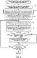
- FIG. 2 is a flow diagram that schematically illustrates a method of correcting a compromised computed tomography image, in accordance with an embodiment of the present invention.
- processor 44 acquires image data from computed tomography scanner 22, stores the image data to memory 50, and generates, based on the acquired image data, a three-dimensional image.
- Step 80 is typically performed prior to a medical procedure to be performed on patient 26.
- operator 40 manipulates handle 38 so that, in an insertion step 82, distal end 42 enters a body cavity in patient 26.
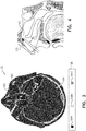
- FIG 3 is a schematic pictorial illustration showing an image slice 100 of a three-dimensional computed tomography image that processor 44 generates in response to receiving the image data from computed tomography scanner 22, and
- Figure 4 is a schematic detail view showing distal end 42 inserted into a sinus cavity 110, in accordance with embodiments of the present invention.
- processor 44 typically incorporates image slice 100 into image 46.
- image slice 100 comprises a two-dimensional "slice" of a head 102 of patient 26.
- Image slice 100 comprises voxels 104 of the three-dimensional image that correspond to three-dimensional locations in the computed tomography image of head 102.
- Processor 44 typically presents each given voxel 104 using different a visual effect that corresponds to the density detected at the three-dimensional location corresponding to the given voxel.
- densities include, but are not limited to, open space, hard body tissue and soft body tissue
- visual effects include, but are not limited to, colors, shadings (e.g., different shades of gray) and patterns (e.g., gradients, pictures, textures, lines, dots and boxes).
- voxels 104 can be differentiated by appending a letter to the identifying numeral, so that the voxels comprise voxels 104A-104C.
- voxels 104A indicate open space and are presented in black
- voxels 104B indicate hard body tissue (e.g., bone) and are presented in white
- voxels 104C indicate soft body tissue (e.g., skin, cartilage, muscle and brain tissue) and are presented in gray. While embodiments herein describe image slice 100 comprising voxels 104 with three different visual effects (i.e. voxels 104A-104C), presenting the voxels with any number of visual effects representing any number of densities is considered to be within the spirit and scope of the present invention.
- Image slice 100 also comprises a region of interest 108.
- region of interest 108 includes interference that processor 44 can correct using embodiments described herein.
- processor 44 registers image coordinate system 28 to sensor coordinate system 62. Upon performing the registration, each three dimensional location indicated by a signal generated by magnetic field sensor 60 corresponds to one or more voxels 104.
- processor 44 receives a signal from magnetic field sensor 60 indicating a location of distal tip 54, and in an identification step 88, the processor uses the registration to identify one or more voxels 104 that correspond to the indicated location.
- a correction step 92 processor 44 corrects the compromised voxel(s). For example, if a given identified voxel 104 has a density value corresponding to hard tissue (i.e. the given identified voxel matches voxel 104B) or soft tissue (i.e., the given identified voxel matches voxel 104C) then processor 44 can update the density value to correspond to the open space (i.e., voxel 104A). In embodiments of the present invention, updating the one or more updated voxels in the image slice presented in image 46 updates the three-dimensional computed tomography image stored in memory 50.
- processor 44 presents image slice 100 on display 48 at the start of the medical procedure.
- image slice 100 comprises a combination of voxels 104A indicating open space, voxels 104B indicating hard tissue and voxels 104C indicating soft tissue. Since distal tip 54 can only be present in open space, embodiments of the present invention correct any given voxel corresponding to a current location of distal tip 54 and having a density value that does not indicate open space.
- processor 44 can update the given voxel by presenting the given voxel with a visual effect indicating open space (i.e., a given white voxel 104 in the example shown in Figure 3 ).
- a second comparison step 94 if operator 40 has completed the medical procedure, then the method ends. However, if operator 40 has not yet completed the medical procedure, then the method continues with step 86. Returning to step 90, if none of the one or more identified voxels are compromised, then the method continues with step 94. While embodiments herein describe processor 44 using magnetic position sensing to correct a compromised computed tomography image, using other types of position sensing to correct other types of medical images is considered to be within the spirit and scope of the present invention.
- FIG. 5 is a schematic pictorial illustration showing region of interest 108 of image slice 100 prior to correcting the computed tomography image, in accordance with an embodiment of the present invention.
- region of interest 108 comprises voxels 104B that indicate a hollow screw 120 and interference 122.
- hollow screw 120 comprises an outer (typically circular) region of voxels 104B (i.e., metal in the screw) surrounding an inner region of voxels 104A (i.e., the hollow region of the screw), and interference 122 comprises "rays" of voxels 104B that radiate from hollow screw 120.
- computed tomography scanner may generate interference 122 due to factors such as the presence of dental work (e.g., tooth fillings) and movement of patient 26 while capturing the image data.
- processor 44 presents interference 122 as hard and soft tissue.
- FIG. 6 is a schematic pictorial illustration showing region of interest 108 of image slice 100 subsequent to correcting the computed tomography image, in accordance with an embodiment of the present invention.
- region of interest 108 comprises corrected regions 130.
- Regions 130 comprise regions which processor 44 assumes are open space because of the presence, detected by the processor, of distal tip 54.
- Display 48 typically presents a subset of voxels 104 that processor 44 can update during a medical procedure using embodiments described herein.
- image slice 100 comprises a two-dimensional "slice" of the three-dimensional image that processor 44 generates in response to receiving the image data from computed tomography scanner 22. Since operator 40 moves distal end 42 in a three-dimensional space (i.e., three-dimensional coordinate systems 28 and 62), it will be understood that there can be additional voxels 104 (i.e., not included in the two-dimensional image slice currently being presented on display 48) whose respective density values are updated by processor 44 in response to detected locations of distal tip 54.
Landscapes
- Engineering & Computer Science (AREA)
- Health & Medical Sciences (AREA)
- Life Sciences & Earth Sciences (AREA)
- Medical Informatics (AREA)
- Physics & Mathematics (AREA)
- General Health & Medical Sciences (AREA)
- Public Health (AREA)
- Nuclear Medicine, Radiotherapy & Molecular Imaging (AREA)
- Heart & Thoracic Surgery (AREA)
- Pathology (AREA)
- Molecular Biology (AREA)
- Surgery (AREA)
- Animal Behavior & Ethology (AREA)
- Biophysics (AREA)
- Radiology & Medical Imaging (AREA)
- Veterinary Medicine (AREA)
- Biomedical Technology (AREA)
- High Energy & Nuclear Physics (AREA)
- Optics & Photonics (AREA)
- Computer Vision & Pattern Recognition (AREA)
- Human Computer Interaction (AREA)
- General Physics & Mathematics (AREA)
- Theoretical Computer Science (AREA)
- Computer Graphics (AREA)
- Geometry (AREA)
- Software Systems (AREA)
- Gynecology & Obstetrics (AREA)
- Quality & Reliability (AREA)
- Apparatus For Radiation Diagnosis (AREA)
- Magnetic Resonance Imaging Apparatus (AREA)
Abstract
Description
- The present invention relates generally to medical imaging, and specifically to correcting a compromised computerized tomography image while performing an invasive medical procedure.
- Superimposing a real-time representation of a medical device, such as a catheter tracked by a medical imaging system (e.g., a computed tomography scanner) during a medical procedure, is known in the art. An image that was previously acquired from a medical imaging system can be used to generate a real-time guide (i.e., a "map") that enables an operator performing the medical procedure to navigate the medical device within a volume of interest in a body of a patient. In order for the superimposition to reflect the true position of the medical device within that volume of interest, it is typically required to register the coordinate system associated with the medical device with the coordinate system associated with the medical imaging system.
- The description above is presented as a general overview of related art in this field and should not be construed as an admission that any of the information it contains constitutes prior art against the present patent application.
- Documents incorporated by reference in the present patent application are to be considered an integral part of the application except that to the extent any terms are defined in these incorporated documents in a manner that conflicts with the definitions made explicitly or implicitly in the present specification, only the definitions in the present specification should be considered.
- There is provided, in accordance with an embodiment of the present invention, a method, including receiving, from an imaging system operating in an image coordinate system, a three-dimensional image of a body cavity including open space and body tissue, receiving, from a medical probe having a location sensor and inserted into the body cavity, a signal indicating a location of a distal tip of the medical probe in a sensor coordinate system, registering, by a processor, the image coordinate system with the sensor coordinate system so as to identify one or more voxels in the three-dimensional image at the indicated location, and when the identified voxels have density values in the received three-dimensional image that do not correspond to the open space, updating the density values of the identified voxels to correspond to the open space. In some embodiments, the imaging system includes a computed tomography scanner. In additional embodiments, the location sensor includes a magnetic field sensor.
- In further embodiments, the method may include forming a correspondence between the density values and visual effects, wherein a given visual effect corresponds to a given density value indicating the open space. In supplemental embodiments, the visual effects may be selected from a group consisting of colors, shadings and patterns.
- In embodiments where the method includes forming a correspondence between the density values and visual effects, the method may include, presenting the three-dimensional image on a display using the visual effects. In some embodiments, the given visual effect includes a first given visual effect, and wherein prior to updating the density values, presenting the three-dimensional image includes presenting, using a second given visual effect different from the first given visual effect, the one or more identified voxels. In additional embodiments, upon updating the density values, presenting the three-dimensional image may include presenting, using the first given visual effect, the one or more identified voxels.
- There is also provided, in accordance with an embodiment of the present invention, an apparatus, including a medical probe configured to be inserted into a body cavity, a location sensor in the medical probe operating in a sensor coordinate system, and a processor configured to receive, from an imaging system operating in an image coordinate system, a three-dimensional image of the body cavity including open space and body tissue, to receive, from the medical probe, a signal indicating a location of a distal tip of the medical probe, to register the image coordinate system with the sensor coordinate system so as to identify one or more voxels in the three-dimensional image at the indicated location, and when the identified voxels have density values in the received three-dimensional image that do not correspond to the open space, to update the density values of the identified voxels to correspond to the open space.
- There is additionally provided, in accordance with an embodiment of the present invention, a computer software product operated in conjunction with a probe that is configured for insertion into a body cavity of a patient and includes a location sensor operating in a sensor coordinate system, the product including a non-transitory computer-readable medium, in which program instructions are stored, which instructions, when read by a computer, cause the computer to receive, from an imaging system operating in an image coordinate system, a three-dimensional image of the body cavity including open space and body tissue, to receive, from the medical probe, a signal indicating a location of a distal tip of the medical probe, to register the image coordinate system with the sensor coordinate system so as to identify one or more voxels in the three-dimensional image at the indicated location, and when the identified voxels have density values in the received three-dimensional image that do not correspond to the open space, to update the density values of the identified voxels to correspond to the open space.
- The disclosure is herein described, by way of example only, with reference to the accompanying drawings, wherein:
-
Figures 1A and1B , referred to collectively asFigure 1 , are schematic pictorial illustrations of a medical system configured to correct, while using a medical probe to perform an invasive medical procedure, a compromised computerized tomography image, in accordance with an embodiment of the present invention; -
Figure 2 is a flow diagram that schematically illustrates a method of correcting the compromised computed tomography image, in accordance with an embodiment of the present invention; -
Figure 3 is a schematic pictorial illustration showing an example of an image slice of a three-dimensional computed tomography image that generated in response to receiving image data from a computed tomography scanner, in accordance with an embodiment of the present invention; -
Figure 4 is a schematic pictorial illustration showing a distal end of the medical prove inserted into a sinus cavity during the medical procedure, in accordance with an embodiment of the present invention; -
Figure 5 is a schematic pictorial illustration showing a region of interest of the image slice prior to correcting the computed tomography image, in accordance with an embodiment of the present invention; and -
Figure 6 is a schematic pictorial illustration showing the region of interest of the image slice subsequent to correcting the computed tomography image, in accordance with an embodiment of the present invention. - Medical images used during medical procedures on a body cavity may sometimes be compromised. For example, computerized tomography images from a computerized tomography scanner can be compromised due to factors such as incorrect settings of the scanner, patient movement, and dental work in proximity to the body cavity. The compromisation is typically presented as noise or clutter on the image.
- Embodiments of the present invention provide methods and systems for correcting a compromised medical image such as a computed tomography image, also referred to herein as a three-dimensional image. As explained hereinbelow, a three-dimensional image of a body cavity comprising open space and body tissue is received from an imaging system operating in an image coordinate system, and a signal is received from a medical probe having a location sensor and inserted into the body cavity, the signal indicating a location of a distal tip of the medical probe in a sensor coordinate system. The image coordinate system is registered with the sensor coordinate system so as to identify one or more voxels in the three-dimensional image at the indicated location, and when the identified voxels have density values in the received three-dimensional image that do not correspond to the open space, the density values of the identified voxels are updated to correspond to the open space.
- Medical imaging systems typically use different visual effects to present open space and body tissue. For example, a computed tomography system may present open space in black, hard body tissue in white and soft body tissue in (various shades of) gray. Since the distal tip of the medical probe can only be inserted into open space, systems implementing embodiments of the present invention can correct, on the three-dimensional image, any locations of the distal tip that are not presented as open space.
-
Figures 1A and1B , referred to collectively asFigure 1 , are schematic pictorial illustrations of amedical system 20 configured to correct a compromised computerized tomography image while performing an invasive medical procedure, in accordance with an embodiment of the present invention. In the example shown inFigure 1 ,medical system 20 comprises a medical imaging system comprising a computed tomography scanner 22, andcontrol console 24, and amedical probe 36. In embodiments described herein, it is assumed thatmedical probe 36 is used for diagnostic or therapeutic treatment, such as minimally invasive catheter-based sinus surgery on apatient 26. Alternatively,medical probe 36 may be used, mutatis mutandis, for other therapeutic and/or diagnostic purposes. - As shown in
Figure 1A , prior to performing an invasive medical procedure onpatient 26, computed tomography scanner 22 generates electrical signals comprising image data for a lumen (e.g., a nasal cavity or a paranasal sinus) of the patient, and conveys the generated image data to controlconsole 24. Computed tomography scanner 22 generates the image data in animage coordinate system 28 comprising anX-axis 30, a Y-axis 32 and a Z-axis 34. - As shown in
Figure 1B ,medical probe 36 comprises ahandle 38 that anoperator 40 can grasp and manipulate in order to insert adistal end 42 of the medical probe into a lumen, such as a nasal cavity or a paranasal sinus, ofpatient 26. In the configuration shown inFigure 1 ,control console 24 comprises aprocessor 44 that converts the received image data into animage 46, and presents the image as information regarding the medical procedure on adisplay 48. -
Display 48 is assumed, by way of example, to comprise a flat panel display such as a liquid crystal display, a light emitting diode display, an organic light-emitting diode display or a plasma display. However, other display devices can also be employed to implement embodiments of the present invention. In some embodiments,display 48 may comprise a touchscreen that can be configured to accept inputs fromoperator 40, in addition to presentingimage 46. - Based on the signals received from
medical probe 36 and other components ofmedical system 20,control console 24drives display 48 to updateimage 46 in order to present a current position ofdistal end 42 in the patient's body, as well as status information and guidance regarding the medical procedure that is in progress.Processor 44 storesdata representing image 46 in amemory 50. In some embodiments,operator 40 can manipulateimage 46 using one ormore input devices 52. In embodiments wheredisplay 48 comprises a touchscreen display,operator 40 can manipulateimage 46 via the touchscreen display.Processor 44 typically comprises a general-purpose computer, with suitable front end and interface circuits for receiving signals frommedical probe 36 and controlling the other components ofcontrol console 24.Processor 44 may be programmed in software to carry out the functions that are described herein. The software may be downloaded to controlconsole 24 in electronic form, over a network, for example, or it may be provided on non-transitory tangible media, such as optical, magnetic or electronic memory media. Alternatively, some or all of the functions ofprocessor 44 may be carried out by dedicated or programmable digital hardware components. - In embodiments described herein,
medical system 20 uses magnetic position sensing to determine position coordinates of a distal tip 54 ofmedical probe 36 insidepatient 26. To implement magnetic based position sensing,control console 24 comprises adriver circuit 56 which drivesfield generators 58 to generate magnetic fields within the body ofpatient 26. Typically,field generators 58 comprise coils, which are placed below the patient at known positions external topatient 26. These coils generate magnetic fields in a predefined working volume that contains a lumen such as a paranasal sinus. A magnetic field sensor 60 (also referred to herein as location sensor 60) withindistal end 42 ofmedical probe 36 generates electrical signals in response to the magnetic fields from the coils, thereby enablingprocessor 44 to determine the position ofdistal end 42 within the cardiac chamber. - Magnetic position tracking techniques are described, for example, in
U.S. Patents 5,391,199 ,6,690,963 ,5,443,489 ,6,788,967 ,5,558,091 ,6,172,499 and6,177,792 , whose disclosures are incorporated herein by reference. The signals generated bymagnetic field sensor 60 indicate the current location of distal tip 54 in asensor coordinate system 62 comprising anX-axis 64, a Y-axis 66 and a Z-axis 68. In the example shown inFigure 1 ,X-axis 64 generally corresponds toX-axis 32, Y-axis 66 generally corresponds to Y-axis 34 and Z-axis 68 generally corresponds to Z-axis 36. - In the example shown in
Figure 1B ,distal end 42 comprises anouter tube 70 having a radial cutting window opening 72 in proximity to distal tip 54, and aninner tube 74 having acutting blade 76. In operation, as cuttingblade 76 traverses radial cuttingwindow opening 72, the cutting blade can remove any body tissue protruding into the cutting window. In some embodiments, a motor (not shown) inhandle 38 rotatesinner tube 74 withinouter tube 70, thereby enablingcutting blade 76 to traverse radialcutting window opening 72. While the example shown inFigure 1B comprises a debrider tool configured to cut and remove body tissue, any other type of medical device comprising alocation sensor 60 and configured to be inserted intopatient 26 is considered to be within the spirit and scope of the present invention. -
Figure 2 is a flow diagram that schematically illustrates a method of correcting a compromised computed tomography image, in accordance with an embodiment of the present invention. In an acquiringstep 80,processor 44 acquires image data from computed tomography scanner 22, stores the image data tomemory 50, and generates, based on the acquired image data, a three-dimensional image.Step 80 is typically performed prior to a medical procedure to be performed onpatient 26. To initiate the medical procedure,operator 40 manipulates handle 38 so that, in aninsertion step 82,distal end 42 enters a body cavity inpatient 26. -
Figure 3 is a schematic pictorial illustration showing animage slice 100 of a three-dimensional computed tomography image thatprocessor 44 generates in response to receiving the image data from computed tomography scanner 22, andFigure 4 is a schematic detail view showingdistal end 42 inserted into asinus cavity 110, in accordance with embodiments of the present invention. In operation,processor 44 typically incorporatesimage slice 100 intoimage 46. - In the example shown in
Figure 3 ,image slice 100 comprises a two-dimensional "slice" of ahead 102 ofpatient 26.Image slice 100 comprisesvoxels 104 of the three-dimensional image that correspond to three-dimensional locations in the computed tomography image ofhead 102.Processor 44 typically presents each givenvoxel 104 using different a visual effect that corresponds to the density detected at the three-dimensional location corresponding to the given voxel. Examples of densities include, but are not limited to, open space, hard body tissue and soft body tissue, and examples of visual effects include, but are not limited to, colors, shadings (e.g., different shades of gray) and patterns (e.g., gradients, pictures, textures, lines, dots and boxes). - As indicated by a
legend 106,voxels 104 can be differentiated by appending a letter to the identifying numeral, so that the voxels comprisevoxels 104A-104C. In the example shown inFigure 3 ,voxels 104A indicate open space and are presented in black,voxels 104B indicate hard body tissue (e.g., bone) and are presented in white, andvoxels 104C indicate soft body tissue (e.g., skin, cartilage, muscle and brain tissue) and are presented in gray. While embodiments herein describeimage slice 100 comprisingvoxels 104 with three different visual effects (i.e. voxels 104A-104C), presenting the voxels with any number of visual effects representing any number of densities is considered to be within the spirit and scope of the present invention. -
Image slice 100 also comprises a region ofinterest 108. As described in the description referencingFigures 5 and 6 hereinbelow, region ofinterest 108 includes interference thatprocessor 44 can correct using embodiments described herein. Returning toFigure 2 , in aregistration step 84,processor 44 registers image coordinatesystem 28 to sensor coordinatesystem 62. Upon performing the registration, each three dimensional location indicated by a signal generated bymagnetic field sensor 60 corresponds to one ormore voxels 104. In a receivingstep 86,processor 44 receives a signal frommagnetic field sensor 60 indicating a location of distal tip 54, and in anidentification step 88, the processor uses the registration to identify one ormore voxels 104 that correspond to the indicated location. - In a
first comparison step 90, if any of the one or more identified voxels are compromised (i.e., have density values indicating that they are not open space), then in acorrection step 92,processor 44 corrects the compromised voxel(s). For example, if a given identifiedvoxel 104 has a density value corresponding to hard tissue (i.e. the given identified voxel matches voxel 104B) or soft tissue (i.e., the given identified voxel matches voxel 104C) thenprocessor 44 can update the density value to correspond to the open space (i.e.,voxel 104A). In embodiments of the present invention, updating the one or more updated voxels in the image slice presented inimage 46 updates the three-dimensional computed tomography image stored inmemory 50. - In operation,
processor 44presents image slice 100 ondisplay 48 at the start of the medical procedure. As described supra,image slice 100 comprises a combination ofvoxels 104A indicating open space,voxels 104B indicating hard tissue andvoxels 104C indicating soft tissue. Since distal tip 54 can only be present in open space, embodiments of the present invention correct any given voxel corresponding to a current location of distal tip 54 and having a density value that does not indicate open space. For example ifprocessor 44 initially presents a givenvoxel 104 with a visual effect indicating that the given voxel is either soft or hard tissue (i.e., gray orblack voxels 104 in the example shown inFigure 3 ), and the processor subsequently detects that distal tip 54 is in a location corresponding to the given voxel, then the processor can update the given voxel by presenting the given voxel with a visual effect indicating open space (i.e., a givenwhite voxel 104 in the example shown inFigure 3 ). - In a
second comparison step 94, ifoperator 40 has completed the medical procedure, then the method ends. However, ifoperator 40 has not yet completed the medical procedure, then the method continues withstep 86. Returning to step 90, if none of the one or more identified voxels are compromised, then the method continues withstep 94. While embodiments herein describeprocessor 44 using magnetic position sensing to correct a compromised computed tomography image, using other types of position sensing to correct other types of medical images is considered to be within the spirit and scope of the present invention. -
Figure 5 is a schematic pictorial illustration showing region ofinterest 108 ofimage slice 100 prior to correcting the computed tomography image, in accordance with an embodiment of the present invention. In addition tovoxels 104A, region ofinterest 108 comprisesvoxels 104B that indicate ahollow screw 120 andinterference 122. In the example shown inFigure 5 ,hollow screw 120 comprises an outer (typically circular) region ofvoxels 104B (i.e., metal in the screw) surrounding an inner region ofvoxels 104A (i.e., the hollow region of the screw), andinterference 122 comprises "rays" ofvoxels 104B that radiate fromhollow screw 120. In operation, computed tomography scanner may generateinterference 122 due to factors such as the presence of dental work (e.g., tooth fillings) and movement ofpatient 26 while capturing the image data. As shown inFigure 5 ,processor 44presents interference 122 as hard and soft tissue. -
Figure 6 is a schematic pictorial illustration showing region ofinterest 108 ofimage slice 100 subsequent to correcting the computed tomography image, in accordance with an embodiment of the present invention. As shown inFigure 6 , region ofinterest 108 comprises correctedregions 130.Regions 130 comprise regions whichprocessor 44 assumes are open space because of the presence, detected by the processor, of distal tip 54. -
Display 48 typically presents a subset ofvoxels 104 thatprocessor 44 can update during a medical procedure using embodiments described herein. As described supra,image slice 100 comprises a two-dimensional "slice" of the three-dimensional image thatprocessor 44 generates in response to receiving the image data from computed tomography scanner 22. Sinceoperator 40 movesdistal end 42 in a three-dimensional space (i.e., three-dimensional coordinatesystems 28 and 62), it will be understood that there can be additional voxels 104 (i.e., not included in the two-dimensional image slice currently being presented on display 48) whose respective density values are updated byprocessor 44 in response to detected locations of distal tip 54. - It will be appreciated that the embodiments described above are cited by way of example, and that the present invention is not limited to what has been particularly shown and described hereinabove. Rather, the scope of the present invention includes both combinations and subcombinations of the various features described hereinabove, as well as variations and modifications thereof which would occur to persons skilled in the art upon reading the foregoing description and which are not disclosed in the prior art.
-
- 1. A method, comprising:
- receiving, from an imaging system operating in an image coordinate system, a three-dimensional image of a body cavity comprising open space and body tissue;
- receiving, from a medical probe having a location sensor and inserted into the body cavity, a signal indicating a location of a distal tip of the medical probe in a sensor coordinate system;
- registering, by a processor, the image coordinate system with the sensor coordinate system so as to identify one or more voxels in the three-dimensional image at the indicated location; and
- when the identified voxels have density values in the received three-dimensional image that do not correspond to the open space, updating the density values of the identified voxels to correspond to the open space.
- 2. The method according to aspect 1, wherein the imaging system comprises a computed tomography scanner.
- 3. The method according to aspect 1, wherein the location sensor comprises a magnetic field sensor.
- 4. The method according to aspect 1, and comprising forming a correspondence between the density values and visual effects, wherein a given visual effect corresponds to a given density value indicating the open space.
- 5. The method according to aspect 4, wherein the visual effects are selected from a group consisting of colors, shadings and patterns.
- 6. The method according to aspect 4, and comprising presenting the three-dimensional image on a display using the visual effects.
- 7. The method according to aspect 6, wherein the given visual effect comprises a first given visual effect, and wherein prior to updating the density values, presenting the three-dimensional image comprises presenting, using a second given visual effect different from the first given visual effect, the one or more identified voxels.
- 8. The method according to aspect 7, wherein upon updating the density values, presenting the three-dimensional image comprises presenting, using the first given visual effect, the one or more identified voxels.
Claims (9)
- An apparatus, comprising:a medical probe configured to be inserted into a body cavity;a location sensor in the medical probe operating in a sensor coordinate system; anda processor configured:to receive, from an imaging system operating in an image coordinate system, a three-dimensional image of the body cavity comprising open space and body tissue;to receive, from the medical probe, a signal indicating a location of a distal tip of the medical probe;to register the image coordinate system with the sensor coordinate system so as to identify one or more voxels in the three-dimensional image at the indicated location; andwhen the identified voxels have density values in the received three-dimensional image that do not correspond to the open space, to update the density values of the identified voxels to correspond to the open space.
- The apparatus according to claim 1, wherein the imaging system comprises a computed tomography scanner.
- The apparatus according to claim 1, wherein the location sensor comprises a magnetic field sensor.
- The apparatus according to claim 1, wherein the processor is configured to form a correspondence between the density values visual effects, wherein a given visual effect corresponds to a given density value indicating the open space.
- The apparatus according to claim 4, wherein the visual effects are selected from a group consisting of colors, shadings and patterns.
- The apparatus according to claim 4, wherein the processor is configured to present the three-dimensional image on a display using the visual effects.
- The apparatus according to claim 6, wherein the given visual effect comprises a first given visual effect, and wherein prior to updating the density values, the processor is configured to present the three-dimensional image by presenting, using a second given visual effect different from the first given visual effect, the one or more identified voxels.
- The apparatus according to claim 7, wherein upon updating the density values, the processor is configured to present the three-dimensional image by presenting, using the first given visual effect, the one or more identified voxels.
- A computer software product, operated in conjunction with a probe that is configured for insertion into a body cavity of a patient and includes a location sensor operating in a sensor coordinate system, the product comprising a non-transitory computer-readable medium, in which program instructions are stored, which instructions, when read by a computer, cause the computer:to receive, from an imaging system operating in an image coordinate system, a three-dimensional image of the body cavity comprising open space and body tissue;to receive, from the medical probe, a signal indicating a location of a distal tip of the medical probe;to register the image coordinate system with the sensor coordinate system so as to identify one or more voxels in the three-dimensional image at the indicated location; andwhen the identified voxels have density values in the received three-dimensional image that do not correspond to the open space, to update the density values of the identified voxels to correspond to the open space.
Applications Claiming Priority (1)
| Application Number | Priority Date | Filing Date | Title |
|---|---|---|---|
| US15/362,518 US10299699B2 (en) | 2016-11-28 | 2016-11-28 | Computerized tomography image correction |
Publications (2)
| Publication Number | Publication Date |
|---|---|
| EP3332709A1 true EP3332709A1 (en) | 2018-06-13 |
| EP3332709B1 EP3332709B1 (en) | 2019-09-04 |
Family
ID=60569614
Family Applications (1)
| Application Number | Title | Priority Date | Filing Date |
|---|---|---|---|
| EP17203897.8A Active EP3332709B1 (en) | 2016-11-28 | 2017-11-27 | Computerized tomography image correction |
Country Status (8)
| Country | Link |
|---|---|
| US (1) | US10299699B2 (en) |
| EP (1) | EP3332709B1 (en) |
| JP (2) | JP6995586B2 (en) |
| CN (1) | CN108113693B (en) |
| AU (1) | AU2017258923A1 (en) |
| CA (1) | CA2986641A1 (en) |
| ES (1) | ES2755904T3 (en) |
| IL (1) | IL255695B (en) |
Cited By (1)
| Publication number | Priority date | Publication date | Assignee | Title |
|---|---|---|---|---|
| CN114842131A (en) * | 2021-02-01 | 2022-08-02 | 伯恩森斯韦伯斯特(以色列)有限责任公司 | Representation of an intra-organ catheter by voxels |
Families Citing this family (4)
| Publication number | Priority date | Publication date | Assignee | Title |
|---|---|---|---|---|
| US11457981B2 (en) * | 2018-10-04 | 2022-10-04 | Acclarent, Inc. | Computerized tomography (CT) image correction using position and direction (P andD) tracking assisted optical visualization |
| US12042163B2 (en) * | 2018-10-05 | 2024-07-23 | Acclarent, Inc. | Hollow tube surgical instrument with single axis sensor |
| US11107213B2 (en) * | 2018-12-28 | 2021-08-31 | Biosense Webster (Israel) Ltd. | Correcting medical scans |
| US10849696B2 (en) * | 2019-03-01 | 2020-12-01 | Biosense Webster (Israel) Ltd. | Map of body cavity |
Citations (8)
| Publication number | Priority date | Publication date | Assignee | Title |
|---|---|---|---|---|
| US5391199A (en) | 1993-07-20 | 1995-02-21 | Biosense, Inc. | Apparatus and method for treating cardiac arrhythmias |
| US5558091A (en) | 1993-10-06 | 1996-09-24 | Biosense, Inc. | Magnetic determination of position and orientation |
| US6172499B1 (en) | 1999-10-29 | 2001-01-09 | Ascension Technology Corporation | Eddy current error-reduced AC magnetic position measurement system |
| US6177792B1 (en) | 1996-03-26 | 2001-01-23 | Bisense, Inc. | Mutual induction correction for radiator coils of an objects tracking system |
| US6690963B2 (en) | 1995-01-24 | 2004-02-10 | Biosense, Inc. | System for determining the location and orientation of an invasive medical instrument |
| WO2007135609A2 (en) * | 2006-05-24 | 2007-11-29 | Koninklijke Philips Electronics, N.V. | Coordinate system registration |
| EP2554103A1 (en) * | 2010-03-31 | 2013-02-06 | FUJIFILM Corporation | Endoscope observation supporting system and method, and device and programme |
| EP2837328A1 (en) * | 2013-08-12 | 2015-02-18 | Biosense Webster (Israel), Ltd. | Unmapped region visualization |
Family Cites Families (27)
| Publication number | Priority date | Publication date | Assignee | Title |
|---|---|---|---|---|
| JPH03232077A (en) * | 1990-02-08 | 1991-10-16 | Toshiba Corp | Picture processor |
| JPH06259541A (en) * | 1992-10-30 | 1994-09-16 | Toshiba Corp | Method for correcting image distorting and its system |
| JP2000126180A (en) * | 1998-10-27 | 2000-05-09 | Mitani Sangyo Co Ltd | Three-dimensional image acquisition device and three-dimensional image acquisition method |
| JP2003153876A (en) * | 2001-11-22 | 2003-05-27 | Ichiro Komada | Surgical operation support device |
| US8088067B2 (en) * | 2002-12-23 | 2012-01-03 | Insightec Ltd. | Tissue aberration corrections in ultrasound therapy |
| DE102004011156A1 (en) * | 2004-03-08 | 2005-10-06 | Siemens Ag | Method for endoluminal imaging with movement correction |
| DE102006025402A1 (en) * | 2006-05-31 | 2007-12-06 | Siemens Ag | Image processing device e.g. frequency discriminator, for producing three dimensional data set, is formed to produce changed object value based on object value as result of pre-determined allocation regulation |
| EP2297673B1 (en) * | 2008-06-03 | 2020-04-22 | Covidien LP | Feature-based registration method |
| EP2521095B1 (en) * | 2008-07-14 | 2015-03-04 | Cefla S.C. | Dynamic error correction in radiographic imaging |
| WO2010018478A1 (en) * | 2008-08-15 | 2010-02-18 | Koninklijke Philips Electronics, N.V. | Attenuation correction for pet or spect nuclear imaging systems using magnetic resonance spectroscopic image data |
| EP2433262B1 (en) * | 2009-05-18 | 2016-07-27 | Koninklijke Philips N.V. | Marker-free tracking registration and calibration for em-tracked endoscopic system |
| US9545242B2 (en) * | 2009-07-31 | 2017-01-17 | Samsung Medison Co., Ltd. | Sensor coordinate calibration in an ultrasound system |
| JP5535725B2 (en) * | 2010-03-31 | 2014-07-02 | 富士フイルム株式会社 | Endoscope observation support system, endoscope observation support device, operation method thereof, and program |
| US8900131B2 (en) * | 2011-05-13 | 2014-12-02 | Intuitive Surgical Operations, Inc. | Medical system providing dynamic registration of a model of an anatomical structure for image-guided surgery |
| US8421021B2 (en) * | 2011-06-21 | 2013-04-16 | General Electric Company | Motion correction of SPECT images |
| WO2013005136A1 (en) * | 2011-07-01 | 2013-01-10 | Koninklijke Philips Electronics N.V. | Intra-operative image correction for image-guided interventions |
| JP5984235B2 (en) * | 2011-07-19 | 2016-09-06 | 東芝メディカルシステムズ株式会社 | Image processing system, apparatus, method, and medical image diagnostic apparatus |
| US9974503B2 (en) * | 2011-07-21 | 2018-05-22 | Carestream Dental Technology Topco Limited | System for paranasal sinus and nasal cavity analysis |
| DE102011087357B4 (en) * | 2011-11-29 | 2021-09-16 | Karl Storz Se & Co. Kg | Updating of pre-operatively recorded 3D image data of a body |
| US8923592B2 (en) * | 2012-05-29 | 2014-12-30 | General Electric Company | Methods and systems for performing attenuation correction |
| CN104379064B (en) * | 2012-06-27 | 2017-09-15 | 东芝医疗系统株式会社 | Ultrasonic diagnostic apparatus and correction method of image data |
| JP2014045943A (en) * | 2012-08-31 | 2014-03-17 | Toshiba Corp | Ultrasound diagnostic apparatus and correction method of image data |
| US20140142419A1 (en) * | 2012-11-19 | 2014-05-22 | Biosense Webster (Israel), Ltd. | Patient movement compensation in intra-body probe |
| EP2932465B1 (en) * | 2012-12-17 | 2018-02-07 | Brainlab AG | Removing image distortions based on movement of an imaging device |
| US9544577B2 (en) * | 2013-07-18 | 2017-01-10 | A.Tron3D Gmbh | Method of capturing three-dimensional (3D) information on a structure |
| CN106462972B (en) * | 2014-04-25 | 2020-09-11 | 通用电气公司 | System and method for evaluating motion correction in dynamic medical images |
| AU2015355134B2 (en) * | 2014-12-01 | 2020-10-08 | Blue Belt Technologies, Inc. | Image free implant revision surgery |
-
2016
- 2016-11-28 US US15/362,518 patent/US10299699B2/en active Active
-
2017
- 2017-11-10 AU AU2017258923A patent/AU2017258923A1/en not_active Abandoned
- 2017-11-15 IL IL255695A patent/IL255695B/en active IP Right Grant
- 2017-11-23 CA CA2986641A patent/CA2986641A1/en not_active Abandoned
- 2017-11-27 JP JP2017226612A patent/JP6995586B2/en active Active
- 2017-11-27 EP EP17203897.8A patent/EP3332709B1/en active Active
- 2017-11-27 ES ES17203897T patent/ES2755904T3/en active Active
- 2017-11-28 CN CN201711223240.8A patent/CN108113693B/en active Active
-
2021
- 2021-12-15 JP JP2021203255A patent/JP7286742B2/en active Active
Patent Citations (10)
| Publication number | Priority date | Publication date | Assignee | Title |
|---|---|---|---|---|
| US5391199A (en) | 1993-07-20 | 1995-02-21 | Biosense, Inc. | Apparatus and method for treating cardiac arrhythmias |
| US5443489A (en) | 1993-07-20 | 1995-08-22 | Biosense, Inc. | Apparatus and method for ablation |
| US5558091A (en) | 1993-10-06 | 1996-09-24 | Biosense, Inc. | Magnetic determination of position and orientation |
| US6690963B2 (en) | 1995-01-24 | 2004-02-10 | Biosense, Inc. | System for determining the location and orientation of an invasive medical instrument |
| US6177792B1 (en) | 1996-03-26 | 2001-01-23 | Bisense, Inc. | Mutual induction correction for radiator coils of an objects tracking system |
| US6788967B2 (en) | 1997-05-14 | 2004-09-07 | Biosense, Inc. | Medical diagnosis, treatment and imaging systems |
| US6172499B1 (en) | 1999-10-29 | 2001-01-09 | Ascension Technology Corporation | Eddy current error-reduced AC magnetic position measurement system |
| WO2007135609A2 (en) * | 2006-05-24 | 2007-11-29 | Koninklijke Philips Electronics, N.V. | Coordinate system registration |
| EP2554103A1 (en) * | 2010-03-31 | 2013-02-06 | FUJIFILM Corporation | Endoscope observation supporting system and method, and device and programme |
| EP2837328A1 (en) * | 2013-08-12 | 2015-02-18 | Biosense Webster (Israel), Ltd. | Unmapped region visualization |
Cited By (3)
| Publication number | Priority date | Publication date | Assignee | Title |
|---|---|---|---|---|
| CN114842131A (en) * | 2021-02-01 | 2022-08-02 | 伯恩森斯韦伯斯特(以色列)有限责任公司 | Representation of an intra-organ catheter by voxels |
| EP4036866A1 (en) * | 2021-02-01 | 2022-08-03 | Biosense Webster (Israel) Ltd. | Catheter representation via voxels within organ |
| US11974817B2 (en) | 2021-02-01 | 2024-05-07 | Biosense Webster (Israel) Ltd. | Catheter representation via voxels within organ |
Also Published As
| Publication number | Publication date |
|---|---|
| IL255695B (en) | 2020-04-30 |
| EP3332709B1 (en) | 2019-09-04 |
| IL255695A0 (en) | 2017-12-31 |
| JP6995586B2 (en) | 2022-01-14 |
| CN108113693A (en) | 2018-06-05 |
| US10299699B2 (en) | 2019-05-28 |
| JP2018086268A (en) | 2018-06-07 |
| JP7286742B2 (en) | 2023-06-05 |
| ES2755904T3 (en) | 2020-04-24 |
| CN108113693B (en) | 2023-03-28 |
| JP2022033168A (en) | 2022-02-28 |
| US20180146883A1 (en) | 2018-05-31 |
| CA2986641A1 (en) | 2018-05-28 |
| AU2017258923A1 (en) | 2018-06-14 |
Similar Documents
| Publication | Publication Date | Title |
|---|---|---|
| JP7286742B2 (en) | computed tomography image correction | |
| EP3166678B1 (en) | Guidewire navigation for sinuplasty | |
| AU2015238800B2 (en) | Real-time simulation of fluoroscopic images | |
| EP3673854B1 (en) | Correcting medical scans | |
| JP2017113559A (en) | Ascertaining position and orientation for visualizing tool | |
| EP3173023A1 (en) | Locally applied transparency for a ct image | |
| CN116829089A (en) | System for updating graphical user interfaces based on intraoperative imaging | |
| WO2021137059A1 (en) | Navigated trocar with internal camera | |
| US7340291B2 (en) | Medical apparatus for tracking movement of a bone fragment in a displayed image | |
| US11786271B2 (en) | Trocar with modular obturator head | |
| EP3547263A1 (en) | Static virtual camera positioning |
Legal Events
| Date | Code | Title | Description |
|---|---|---|---|
| PUAI | Public reference made under article 153(3) epc to a published international application that has entered the european phase |
Free format text: ORIGINAL CODE: 0009012 |
|
| STAA | Information on the status of an ep patent application or granted ep patent |
Free format text: STATUS: THE APPLICATION HAS BEEN PUBLISHED |
|
| AK | Designated contracting states |
Kind code of ref document: A1 Designated state(s): AL AT BE BG CH CY CZ DE DK EE ES FI FR GB GR HR HU IE IS IT LI LT LU LV MC MK MT NL NO PL PT RO RS SE SI SK SM TR |
|
| AX | Request for extension of the european patent |
Extension state: BA ME |
|
| STAA | Information on the status of an ep patent application or granted ep patent |
Free format text: STATUS: REQUEST FOR EXAMINATION WAS MADE |
|
| 17P | Request for examination filed |
Effective date: 20181203 |
|
| RBV | Designated contracting states (corrected) |
Designated state(s): AL AT BE BG CH CY CZ DE DK EE ES FI FR GB GR HR HU IE IS IT LI LT LU LV MC MK MT NL NO PL PT RO RS SE SI SK SM TR |
|
| GRAP | Despatch of communication of intention to grant a patent |
Free format text: ORIGINAL CODE: EPIDOSNIGR1 |
|
| STAA | Information on the status of an ep patent application or granted ep patent |
Free format text: STATUS: GRANT OF PATENT IS INTENDED |
|
| RIC1 | Information provided on ipc code assigned before grant |
Ipc: A61B 90/00 20160101ALI20190329BHEP Ipc: A61B 6/00 20060101AFI20190329BHEP Ipc: A61B 6/03 20060101ALN20190329BHEP |
|
| INTG | Intention to grant announced |
Effective date: 20190424 |
|
| GRAS | Grant fee paid |
Free format text: ORIGINAL CODE: EPIDOSNIGR3 |
|
| GRAA | (expected) grant |
Free format text: ORIGINAL CODE: 0009210 |
|
| STAA | Information on the status of an ep patent application or granted ep patent |
Free format text: STATUS: THE PATENT HAS BEEN GRANTED |
|
| RAP1 | Party data changed (applicant data changed or rights of an application transferred) |
Owner name: BIOSENSE WEBSTER (ISRAEL) LTD. |
|
| AK | Designated contracting states |
Kind code of ref document: B1 Designated state(s): AL AT BE BG CH CY CZ DE DK EE ES FI FR GB GR HR HU IE IS IT LI LT LU LV MC MK MT NL NO PL PT RO RS SE SI SK SM TR |
|
| REG | Reference to a national code |
Ref country code: GB Ref legal event code: FG4D |
|
| REG | Reference to a national code |
Ref country code: CH Ref legal event code: EP Ref country code: CH Ref legal event code: NV Representative=s name: E. BLUM AND CO. AG PATENT- UND MARKENANWAELTE , CH |
|
| REG | Reference to a national code |
Ref country code: AT Ref legal event code: REF Ref document number: 1174222 Country of ref document: AT Kind code of ref document: T Effective date: 20190915 |
|
| REG | Reference to a national code |
Ref country code: DE Ref legal event code: R096 Ref document number: 602017006749 Country of ref document: DE |
|
| REG | Reference to a national code |
Ref country code: IE Ref legal event code: FG4D |
|
| REG | Reference to a national code |
Ref country code: NL Ref legal event code: FP |
|
| REG | Reference to a national code |
Ref country code: LT Ref legal event code: MG4D |
|
| PG25 | Lapsed in a contracting state [announced via postgrant information from national office to epo] |
Ref country code: SE Free format text: LAPSE BECAUSE OF FAILURE TO SUBMIT A TRANSLATION OF THE DESCRIPTION OR TO PAY THE FEE WITHIN THE PRESCRIBED TIME-LIMIT Effective date: 20190904 Ref country code: NO Free format text: LAPSE BECAUSE OF FAILURE TO SUBMIT A TRANSLATION OF THE DESCRIPTION OR TO PAY THE FEE WITHIN THE PRESCRIBED TIME-LIMIT Effective date: 20191204 Ref country code: FI Free format text: LAPSE BECAUSE OF FAILURE TO SUBMIT A TRANSLATION OF THE DESCRIPTION OR TO PAY THE FEE WITHIN THE PRESCRIBED TIME-LIMIT Effective date: 20190904 Ref country code: HR Free format text: LAPSE BECAUSE OF FAILURE TO SUBMIT A TRANSLATION OF THE DESCRIPTION OR TO PAY THE FEE WITHIN THE PRESCRIBED TIME-LIMIT Effective date: 20190904 Ref country code: BG Free format text: LAPSE BECAUSE OF FAILURE TO SUBMIT A TRANSLATION OF THE DESCRIPTION OR TO PAY THE FEE WITHIN THE PRESCRIBED TIME-LIMIT Effective date: 20191204 Ref country code: LT Free format text: LAPSE BECAUSE OF FAILURE TO SUBMIT A TRANSLATION OF THE DESCRIPTION OR TO PAY THE FEE WITHIN THE PRESCRIBED TIME-LIMIT Effective date: 20190904 |
|
| PG25 | Lapsed in a contracting state [announced via postgrant information from national office to epo] |
Ref country code: AL Free format text: LAPSE BECAUSE OF FAILURE TO SUBMIT A TRANSLATION OF THE DESCRIPTION OR TO PAY THE FEE WITHIN THE PRESCRIBED TIME-LIMIT Effective date: 20190904 Ref country code: GR Free format text: LAPSE BECAUSE OF FAILURE TO SUBMIT A TRANSLATION OF THE DESCRIPTION OR TO PAY THE FEE WITHIN THE PRESCRIBED TIME-LIMIT Effective date: 20191205 Ref country code: LV Free format text: LAPSE BECAUSE OF FAILURE TO SUBMIT A TRANSLATION OF THE DESCRIPTION OR TO PAY THE FEE WITHIN THE PRESCRIBED TIME-LIMIT Effective date: 20190904 Ref country code: RS Free format text: LAPSE BECAUSE OF FAILURE TO SUBMIT A TRANSLATION OF THE DESCRIPTION OR TO PAY THE FEE WITHIN THE PRESCRIBED TIME-LIMIT Effective date: 20190904 |
|
| REG | Reference to a national code |
Ref country code: AT Ref legal event code: MK05 Ref document number: 1174222 Country of ref document: AT Kind code of ref document: T Effective date: 20190904 |
|
| REG | Reference to a national code |
Ref country code: ES Ref legal event code: FG2A Ref document number: 2755904 Country of ref document: ES Kind code of ref document: T3 Effective date: 20200424 |
|
| PG25 | Lapsed in a contracting state [announced via postgrant information from national office to epo] |
Ref country code: PT Free format text: LAPSE BECAUSE OF FAILURE TO SUBMIT A TRANSLATION OF THE DESCRIPTION OR TO PAY THE FEE WITHIN THE PRESCRIBED TIME-LIMIT Effective date: 20200106 Ref country code: EE Free format text: LAPSE BECAUSE OF FAILURE TO SUBMIT A TRANSLATION OF THE DESCRIPTION OR TO PAY THE FEE WITHIN THE PRESCRIBED TIME-LIMIT Effective date: 20190904 Ref country code: PL Free format text: LAPSE BECAUSE OF FAILURE TO SUBMIT A TRANSLATION OF THE DESCRIPTION OR TO PAY THE FEE WITHIN THE PRESCRIBED TIME-LIMIT Effective date: 20190904 Ref country code: RO Free format text: LAPSE BECAUSE OF FAILURE TO SUBMIT A TRANSLATION OF THE DESCRIPTION OR TO PAY THE FEE WITHIN THE PRESCRIBED TIME-LIMIT Effective date: 20190904 Ref country code: AT Free format text: LAPSE BECAUSE OF FAILURE TO SUBMIT A TRANSLATION OF THE DESCRIPTION OR TO PAY THE FEE WITHIN THE PRESCRIBED TIME-LIMIT Effective date: 20190904 |
|
| PG25 | Lapsed in a contracting state [announced via postgrant information from national office to epo] |
Ref country code: IS Free format text: LAPSE BECAUSE OF FAILURE TO SUBMIT A TRANSLATION OF THE DESCRIPTION OR TO PAY THE FEE WITHIN THE PRESCRIBED TIME-LIMIT Effective date: 20200224 Ref country code: CZ Free format text: LAPSE BECAUSE OF FAILURE TO SUBMIT A TRANSLATION OF THE DESCRIPTION OR TO PAY THE FEE WITHIN THE PRESCRIBED TIME-LIMIT Effective date: 20190904 Ref country code: SM Free format text: LAPSE BECAUSE OF FAILURE TO SUBMIT A TRANSLATION OF THE DESCRIPTION OR TO PAY THE FEE WITHIN THE PRESCRIBED TIME-LIMIT Effective date: 20190904 Ref country code: SK Free format text: LAPSE BECAUSE OF FAILURE TO SUBMIT A TRANSLATION OF THE DESCRIPTION OR TO PAY THE FEE WITHIN THE PRESCRIBED TIME-LIMIT Effective date: 20190904 |
|
| REG | Reference to a national code |
Ref country code: DE Ref legal event code: R097 Ref document number: 602017006749 Country of ref document: DE |
|
| PLBE | No opposition filed within time limit |
Free format text: ORIGINAL CODE: 0009261 |
|
| STAA | Information on the status of an ep patent application or granted ep patent |
Free format text: STATUS: NO OPPOSITION FILED WITHIN TIME LIMIT |
|
| PG2D | Information on lapse in contracting state deleted |
Ref country code: IS |
|
| PG25 | Lapsed in a contracting state [announced via postgrant information from national office to epo] |
Ref country code: DK Free format text: LAPSE BECAUSE OF FAILURE TO SUBMIT A TRANSLATION OF THE DESCRIPTION OR TO PAY THE FEE WITHIN THE PRESCRIBED TIME-LIMIT Effective date: 20190904 Ref country code: MC Free format text: LAPSE BECAUSE OF FAILURE TO SUBMIT A TRANSLATION OF THE DESCRIPTION OR TO PAY THE FEE WITHIN THE PRESCRIBED TIME-LIMIT Effective date: 20190904 Ref country code: LU Free format text: LAPSE BECAUSE OF NON-PAYMENT OF DUE FEES Effective date: 20191127 Ref country code: IS Free format text: LAPSE BECAUSE OF FAILURE TO SUBMIT A TRANSLATION OF THE DESCRIPTION OR TO PAY THE FEE WITHIN THE PRESCRIBED TIME-LIMIT Effective date: 20200105 |
|
| 26N | No opposition filed |
Effective date: 20200605 |
|
| PG25 | Lapsed in a contracting state [announced via postgrant information from national office to epo] |
Ref country code: SI Free format text: LAPSE BECAUSE OF FAILURE TO SUBMIT A TRANSLATION OF THE DESCRIPTION OR TO PAY THE FEE WITHIN THE PRESCRIBED TIME-LIMIT Effective date: 20190904 |
|
| PG25 | Lapsed in a contracting state [announced via postgrant information from national office to epo] |
Ref country code: CY Free format text: LAPSE BECAUSE OF FAILURE TO SUBMIT A TRANSLATION OF THE DESCRIPTION OR TO PAY THE FEE WITHIN THE PRESCRIBED TIME-LIMIT Effective date: 20190904 |
|
| PG25 | Lapsed in a contracting state [announced via postgrant information from national office to epo] |
Ref country code: HU Free format text: LAPSE BECAUSE OF FAILURE TO SUBMIT A TRANSLATION OF THE DESCRIPTION OR TO PAY THE FEE WITHIN THE PRESCRIBED TIME-LIMIT; INVALID AB INITIO Effective date: 20171127 Ref country code: MT Free format text: LAPSE BECAUSE OF FAILURE TO SUBMIT A TRANSLATION OF THE DESCRIPTION OR TO PAY THE FEE WITHIN THE PRESCRIBED TIME-LIMIT Effective date: 20190904 |
|
| PG25 | Lapsed in a contracting state [announced via postgrant information from national office to epo] |
Ref country code: TR Free format text: LAPSE BECAUSE OF FAILURE TO SUBMIT A TRANSLATION OF THE DESCRIPTION OR TO PAY THE FEE WITHIN THE PRESCRIBED TIME-LIMIT Effective date: 20190904 |
|
| PG25 | Lapsed in a contracting state [announced via postgrant information from national office to epo] |
Ref country code: MK Free format text: LAPSE BECAUSE OF FAILURE TO SUBMIT A TRANSLATION OF THE DESCRIPTION OR TO PAY THE FEE WITHIN THE PRESCRIBED TIME-LIMIT Effective date: 20190904 |
|
| PGFP | Annual fee paid to national office [announced via postgrant information from national office to epo] |
Ref country code: NL Payment date: 20221019 Year of fee payment: 6 |
|
| PGFP | Annual fee paid to national office [announced via postgrant information from national office to epo] |
Ref country code: IE Payment date: 20221011 Year of fee payment: 6 |
|
| PGFP | Annual fee paid to national office [announced via postgrant information from national office to epo] |
Ref country code: CH Payment date: 20221103 Year of fee payment: 6 Ref country code: BE Payment date: 20221019 Year of fee payment: 6 |
|
| REG | Reference to a national code |
Ref country code: CH Ref legal event code: PL |
|
| REG | Reference to a national code |
Ref country code: NL Ref legal event code: MM Effective date: 20231201 |
|
| PG25 | Lapsed in a contracting state [announced via postgrant information from national office to epo] |
Ref country code: CH Free format text: LAPSE BECAUSE OF NON-PAYMENT OF DUE FEES Effective date: 20231130 |
|
| PG25 | Lapsed in a contracting state [announced via postgrant information from national office to epo] |
Ref country code: CH Free format text: LAPSE BECAUSE OF NON-PAYMENT OF DUE FEES Effective date: 20231130 |
|
| REG | Reference to a national code |
Ref country code: BE Ref legal event code: MM Effective date: 20231130 |
|
| PG25 | Lapsed in a contracting state [announced via postgrant information from national office to epo] |
Ref country code: NL Free format text: LAPSE BECAUSE OF NON-PAYMENT OF DUE FEES Effective date: 20231201 |
|
| REG | Reference to a national code |
Ref country code: IE Ref legal event code: MM4A |
|
| PG25 | Lapsed in a contracting state [announced via postgrant information from national office to epo] |
Ref country code: NL Free format text: LAPSE BECAUSE OF NON-PAYMENT OF DUE FEES Effective date: 20231201 |
|
| PG25 | Lapsed in a contracting state [announced via postgrant information from national office to epo] |
Ref country code: IE Free format text: LAPSE BECAUSE OF NON-PAYMENT OF DUE FEES Effective date: 20231127 |
|
| PG25 | Lapsed in a contracting state [announced via postgrant information from national office to epo] |
Ref country code: BE Free format text: LAPSE BECAUSE OF NON-PAYMENT OF DUE FEES Effective date: 20231130 |
|
| PG25 | Lapsed in a contracting state [announced via postgrant information from national office to epo] |
Ref country code: IE Free format text: LAPSE BECAUSE OF NON-PAYMENT OF DUE FEES Effective date: 20231127 Ref country code: BE Free format text: LAPSE BECAUSE OF NON-PAYMENT OF DUE FEES Effective date: 20231130 |
|
| PGFP | Annual fee paid to national office [announced via postgrant information from national office to epo] |
Ref country code: FR Payment date: 20250930 Year of fee payment: 9 |
|
| PGFP | Annual fee paid to national office [announced via postgrant information from national office to epo] |
Ref country code: DE Payment date: 20250930 Year of fee payment: 9 |
|
| PGFP | Annual fee paid to national office [announced via postgrant information from national office to epo] |
Ref country code: GB Payment date: 20251001 Year of fee payment: 9 |
|
| PGFP | Annual fee paid to national office [announced via postgrant information from national office to epo] |
Ref country code: IT Payment date: 20251022 Year of fee payment: 9 |
|
| PGFP | Annual fee paid to national office [announced via postgrant information from national office to epo] |
Ref country code: ES Payment date: 20251211 Year of fee payment: 9 |