EP3332676A1 - Electric pressure cooker - Google Patents
Electric pressure cooker Download PDFInfo
- Publication number
- EP3332676A1 EP3332676A1 EP16911458.4A EP16911458A EP3332676A1 EP 3332676 A1 EP3332676 A1 EP 3332676A1 EP 16911458 A EP16911458 A EP 16911458A EP 3332676 A1 EP3332676 A1 EP 3332676A1
- Authority
- EP
- European Patent Office
- Prior art keywords
- pressure cooker
- electric pressure
- pot
- cooker according
- electromagnetic heating
- Prior art date
- Legal status (The legal status is an assumption and is not a legal conclusion. Google has not performed a legal analysis and makes no representation as to the accuracy of the status listed.)
- Granted
Links
Images









Classifications
-
- A—HUMAN NECESSITIES
- A47—FURNITURE; DOMESTIC ARTICLES OR APPLIANCES; COFFEE MILLS; SPICE MILLS; SUCTION CLEANERS IN GENERAL
- A47J—KITCHEN EQUIPMENT; COFFEE MILLS; SPICE MILLS; APPARATUS FOR MAKING BEVERAGES
- A47J27/00—Cooking-vessels
- A47J27/08—Pressure-cookers; Lids or locking devices specially adapted therefor
- A47J27/086—Pressure-cookers; Lids or locking devices specially adapted therefor with built-in heating means
Definitions
- the present disclosure relates to a technical field of electric appliance manufacturing, and more particularly to an electric pressure cooker.
- an electric heating plate having a heating tube is provided to an outer pot so as to heat an inner pot. Adopting this heating method causes a very high thermal inertia and a poor controllability in temperature and pressure, thus resulting in a low pressure control precision of the pressure cooker, and hence influencing a cooking effect.
- Embodiments of the present disclosure seek to solve at least one of the problems existing in the related art to at least some extent. For this reason, the present disclosure provides an electric pressure cooker, which has advantages of a low thermal inertia, a good controllability, a high production efficiency, a good heating effect and a high reliability.
- an electric pressure cooker is provided according to embodiments of the present disclosure.
- the electric pressure cooker includes an outer pot provided with a support rib at a lower end of the outer pot; a supporting member disposed in the outer pot and supported on the support rib; an inner pot disposed in the outer pot and supported on the supporting member, and an outer bottom surface of the inner pot being spaced apart from an inner bottom surface of the outer pot, under support of the supporting member; and an electromagnetic heating device configured to heat the inner pot, and disposed between the outer bottom surface of the inner pot and the inner bottom surface of the outer pot.
- the electric pressure cooker according to embodiments of the present disclosure has advantages of a low thermal inertia, a good controllability, a high production efficiency, a good heating effect and a high reliability.
- the electric pressure cooker according to the above embodiments of the present disclosure may have following additional technical features.
- the supporting member is configured as a rigid supporting member.
- the rigid supporting member includes a plurality of supporting pillars arranged along a circumferential direction of the inner pot and spaced apart from one another.
- an outer circumferential edge of the outer bottom surface of the inner pot is supported on the plurality of supporting pillars.
- the rigid supporting member further includes a connecting ring extending in the circumferential direction of the inner pot and respectively connected with the plurality of supporting pillars, and the electromagnetic heating device is fitted in the connecting ring.
- the plurality of supporting pillars are connected to a lower surface of the connecting ring, and the inner pot is supported on the connecting ring.
- the rigid supporting member is configured as an annular supporting boss extending in the circumferential direction of the inner pot, and the electromagnetic heating device is fitted in the annular supporting boss.
- an inner bottom wall of the outer pot is provided with a supporting-member positioning groove, and the rigid supporting member is fitted in the supporting-member positioning groove.
- the electric pressure cooker further includes a fan
- the housing is provided with an air inlet and an air outlet
- the fan is disposed between an inner surface of the housing and an outer surface of the outer pot.
- a bottom wall of the outer pot is provided with a heat dissipation opening, and the fan is disposed between the bottom wall of the outer pot and a bottom wall of the housing.
- a sectional area of the heat dissipation opening is larger than 1500 square millimeters.
- a ventilation notch is provided at a junction between a circumferential wall and a bottom wall of the outer pot.
- a depth of the ventilation notch in a vertical direction is less than 90 millimeters, and a width of the ventilation notch in a circumferential direction of the outer pot is less than 200 millimeters.
- a distance between the fan and the bottom wall of the outer pot is less than or equal to 150 millimeters.
- the electric pressure cooker further includes a power supply board, the power supply board is located between an outer circumferential wall of the outer pot and an inner circumferential wall of the housing and is arranged adjacent to the fan.
- an end of the power supply board adjacent to the fan is provided with a cooling fin.
- the power supply board is oriented in the vertical direction, and the cooling fin extends from the power supply board to the housing.
- the housing is provided with a wind deflector, the wind deflector is oriented in the vertical direction and spaced apart from the cooling fin.
- a distance between the wind deflector and the cooling fin is less than or equal to 30 millimeters.
- the fan is located above the air inlet.
- the housing includes a base, the air inlet and the air outlet both are provided to the base and respectively adjacent to two ends of the base.
- the housing is provided with a supporting foot at a bottom thereof, and a length of the supporting foot away from a lower surface of the housing is 1-75 millimeters.
- an inner circumferential edge of the heat dissipation opening is provided with an upper turn-up.
- a height of the upper turn-up in the vertical direction is 1-15 millimeters.
- an elastic member is provided below the supporting member, and the supporting member is supported on the elastic member.
- the elastic member is configured to be deformed when a pressure in the inner pot reaches a pre-determined value, so as to release the pressure in the inner pot.
- the elastic member is configured to be deformed to move the inner pot downwards when the pressure in the inner pot reaches the pre-determined value.
- the circumferential wall of the outer pot is provided with a circumferential-wall reinforcing rib
- the bottom wall of the outer pot is provided with a bottom-wall reinforcing rib
- two ends of the elastic member are respectively supported on the bottom-wall reinforcing rib
- the supporting member is supported at a center of the elastic member in a length direction of the elastic member.
- the elastic member has a plate shape and a width of the elastic member is gradually increased from two ends of the elastic member to a middle of the elastic member.
- the supporting member is provided with a mounting hole
- the outer pot is provided with an outer-pot through hole
- the elastic member is provided with an elastic-member through hole
- the supporting member is mounted to the outer pot through a threaded fastener fitted in the mounting hole, the outer-pot through hole and the elastic-member through hole.
- a height of the bottom-wall reinforcing rib away from the bottom wall of the outer pot is less than 30 millimeters.
- the outer pot is formed by stamping a cold-rolled sheet, and a thickness of the cold-rolled sheet is 0.4-2 millimeters.
- the electromagnetic heating device includes an electromagnetic heating plate, and a projection of the electromagnetic heating plate in a horizontal direction is staggered with a projection of the supporting member in the horizontal direction.
- the electromagnetic heating plate is spaced apart from at least one of the inner bottom surface of the outer pot and the outer bottom surface of the inner pot.
- the electromagnetic heating plate is spaced apart from the inner bottom surface of the outer pot and the outer bottom surface of the inner pot respectively, and is more adjacent to the outer bottom surface of the inner pot with respect to the inner bottom surface of the outer pot.
- the electromagnetic heating device further includes a holder, the holder is disposed between the outer bottom surface of the inner pot and the inner bottom surface of the outer pot, the supporting member is disposed to the holder, and the electromagnetic heating plate is provided to the holder.
- the holder is provided with mounting holes spaced apart from one another in a circumferential direction of the holder, and the supporting member is fitted in the mounting hole.
- the electromagnetic heating plate includes; a coil plate provided with a coil slot therein; a coil fitted in the coil slot; and a magnetic stripe disposed to the coil plate.
- the electromagnetic heating plate further includes a magnetic-stripe fixing frame, the magnetic-stripe fixing frame is mounted to the coil plate, and the magnetic stripe is mounted to the magnetic-stripe fixing frame.
- the coil plate and the holder are integrally molded.
- the coil plate is connected to the holder through a threaded fastener.
- the magnetic-stripe fixing frame is provided with a magnetic-stripe mounting groove
- the coil plate is provided with a magnetic-stripe positioning groove
- the magnetic stripe is provided with a positioning protrusion
- the magnetic stripe is fitted in the magnetic-stripe mounting groove and the positioning protrusion is fitted in the magnetic-stripe positioning groove.
- the positioning protrusion includes an inner positioning protrusion and an outer positioning protrusion respectively located at two ends of the magnetic stripe
- the magnetic-stripe positioning groove includes an inner positioning groove disposed adjacent to a center of the coil plate and an outer positioning groove disposed adjacent to an outer circumferential edge of the coil plate, the inner positioning protrusion is fitted in the inner positioning groove and the outer positioning protrusion is fitted in the outer positioning groove.
- an outer edge of the magnetic-stripe fixing frame is provided with a relief groove for escaping the supporting member.
- an upper surface of the holder is provided with a decoration cover, and the decoration cover is provided with a through hole for escaping the supporting member.
- the electric pressure cooker 1 includes an outer pot 100, a supporting member 200, an inner pot 300 and an electromagnetic heating device 400.
- a lower end of the outer pot 100 is provided with a support rib 110 (an up and down direction is shown by arrow A in Figs. 1-4 ).
- the supporting member 200 is disposed in the outer pot 100 and supported on the support rib 110.
- the inner pot 300 is disposed in the outer pot 100 and supported on the supporting member 200. Under support of the supporting member 200, an outer bottom surface of the inner pot 300 is spaced apart from an inner bottom surface of the outer pot 100.
- the electromagnetic heating device 400 is used for heating the inner pot 300, and the electromagnetic heating device 400 is disposed between the outer bottom surface of the inner pot 300 and the inner bottom surface of the outer pot 100.
- the inner pot 300 can be electromagnetically heated by the electromagnetic heating device 400.
- the electromagnetic heating can reduce a thermal inertia, make it convenient to control the temperature, and improve a control precision over the temperature and pressure, thereby improving a cooking effect of the electric pressure cooker 1.
- the supporting member 200 can be supported on the support rib 110, such that the supporting member 200 can be conveniently supported on the outer pot 10, so as to ensure an supporting effect of the supporting member 200 on the inner pot 300, and a bottom wall of the outer pot 100 can be conveniently processed, for example the bottom wall of the outer pot 100 is opened, so as to facilitate heat dissipation.
- the supporting member 200 can be used to support the inner pot 300.
- a pressure in the inner pot 300 is increased to produce a downward thrust.
- a force acted on the inner pot 300 is transmitted to the outer pot 100 through the supporting member 200. Since the supporting member 200 is supported between the inner pot 300 and the outer pot 100, the outer bottom surface of the inner pot 300 and the inner bottom surface of the outer pot 100 can be kept apart from each other, when the electric pressure cooker 1 operates, so as to prevent the inner pot 300 and the outer pot 100 from squeezing the electromagnetic heating device 400, thereby preventing the electromagnetic heating device 400 from being damaged and improving the reliability of the electromagnetic heating device 400.
- the supporting member 200 can escape the electromagnetic heating plate 410, such that the supporting member 200 is prevented from hindering the arrangement of the electromagnetic heating plate 410, and the electromagnetic heating plate 410 and the bottom wall of the inner pot 300 will not be blocked by the supporting member 200 therebetween.
- the electromagnetic heating plate 410 can be arranged as close as possible to the bottom wall of the inner pot 300, so as to improve a heating effect of the electromagnetic heating plate 410 on the inner pot 300 and improve the heating efficiency of the electromagnetic heating device 400.
- a distance between the inner bottom surface of the outer pot 100 and the outer bottom surface of the inner pot 300 can be conveniently controlled, leaving more space for the arrangement of the electromagnetic heating device 400, furthermore preventing the electromagnetic heating device 400 from being damaged under stress.
- the electric pressure cooker 1 has advantages of a low thermal inertia, a good controllability, a high production efficiency, a good heating effect and a high reliability.
- the electric pressure cooker 1 includes the outer pot 100, the supporting member 200, the inner pot 300 and the electromagnetic heating device 400.
- a supporting pillar 210 is a rigid supporting member.
- the supporting member 200 is disposed in the outer pot 100.
- the inner pot 300 is disposed in the outer pot 100 and supported on the supporting member 200. Under support of the supporting member 200, the outer bottom surface of the inner pot 300 is spaced apart from the inner bottom surface of the outer pot 100.
- the electromagnetic heating device 400 is used for heating the inner pot 300, and the electromagnetic heating device 400 is disposed between the outer bottom surface of the inner pot 300 and the inner bottom surface of the outer pot 100.
- the electromagnetic heating device 400 includes the electromagnetic heating plate 410, and the projection of the electromagnetic heating plate 410 in the horizontal direction is staggered with the projection of the supporting member 200 in the horizontal direction.
- the electromagnetic heating plate 410 refers to a structure of the electromagnetic heating device 400 for achieving the electromagnetic heating function.
- the expression “the electromagnetic heating device 400 includes the electromagnetic heating plate 410” may indicate that the electromagnetic heating device 400 includes the electromagnetic heating plate 410 and other structures, and may also indicate that the electromagnetic heating device 400 is the electromagnetic heating plate 410.
- the expression “the projection of the electromagnetic heating plate 410 in the horizontal direction is staggered with the projection of the supporting member 200 in the horizontal direction” indicates that the projection of the electromagnetic heating plate 410 in the horizontal direction and the projection of the supporting member 200 in the horizontal direction are not overlapped.
- the rigid supporting member 200 to support the inner pot 300, compared with the method of using an elastic member to support the inner pot 300, it can be avoided that an elastic force of the elastic member is reduced or even fails due to a long time service or an excessive pressure, and since the inner pot 300 and the outer pot 100 will not produce a relative movement, a space for compressing the elastic member does not need to be reserved between the outer pot 100 and the inner pot 300, such that, on one hand, it is convenient to control a dimension of the electric pressure cooker 1, and on the other hand, the electromagnetic heating device 400 can be further avoided from being damaged under stress.
- the electric pressure cooker 1 includes the outer pot 100, the supporting member 200, the inner pot 300 and the electromagnetic heating device 400.
- the lower end of the outer pot 100 is provided with the support rib 110.
- the bottom wall of the outer pot 100 is provided with a heat dissipation opening 120, and the support rib 110 is formed to an inner circumferential wall of the heat dissipation opening 120.
- the heat dissipation opening 120 may be substantially triangle-shaped.
- an airflow can pass through the heat dissipation opening 120, so as to cool the outer pot 100 conveniently, and also the heating of the electromagnetic heating device 400 on the bottom of the outer pot 100 can be reduced, thereby further facilitating the cooling and the heat dissipation of the outer pot 100.
- the support rib 110 can be constituted by a portion of the bottom wall of the outer pot 100 apart from the heat dissipation opening 120.
- the electromagnetic heating plate 410 is spaced apart from at least one of the inner bottom surface of the outer pot 100 and the outer bottom surface of the inner pot 300. Thus, it is convenient for the electromagnetic heating device 400 to be arranged, and also the electromagnetic heating device 400 can be further prevented from being damaged due to squeeze of the outer pot 100 and the inner pot 300.
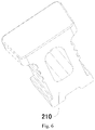
- the supporting member 200 includes a plurality of supporting pillars 210 arranged along a circumferential direction of the inner pot 300 and spaced apart from each other. Specifically, the plurality of supporting pillars 210 are arranged at equal intervals while surrounding the electromagnetic heating plate 410. Thus, the plurality of supporting pillars 210 can be used to support the inner pot 300, so that it is convenient to support the inner pot 300, and also to transmit the force acted on the inner pot 300 to the outer pot 100 by means of the supporting member 200.
- three supporting pillars 210 may be provided, thus facilitating the support for the inner pot 300 and ensuring the stability of the inner pot 300.
- an outer circumferential edge of the outer bottom surface of the inner pot 300 is supported on the plurality of supporting pillars 210.
- the electromagnetic heating device 400 further includes a holder 420, the electromagnetic heating plate 410 is provided to the holder 420, the holder 420 is provided with a plurality of mounting holes, and the plurality of supporting pillars 210 are fitted in the plurality of mounting holes correspondingly.
- the holder 420 may be spaced apart from the inner pot 300 or may be fitted closely with the inner pot 300, but the holder 420 is used for positioning the electromagnetic heating plate 410, rather than supporting the inner pot 300.
- the electromagnetic heating plate 410 is disposed to a lower surface of the holder 420, which thus facilitates the positioning of the supporting pillar 210 and the electromagnetic heating device 400, so as to facilitate the mounting of the supporting pillar 210 and the electromagnetic heating device 400, and also avoids the supporting pillar 210 from producing a force component when being pressured, so as to improve the stability of the supporting member 200.
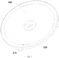
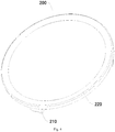
- the supporting member 200 further includes a connecting ring 220 extending in the circumferential direction of the inner pot 300 and respectively connected with the plurality of supporting pillars 210, and the electromagnetic heating device 400 is fitted in the connecting ring 220.
- the supporting pillar 210 and the connecting ring 220 may be integrally molded.
- the plurality of supporting pillars 210 are connected to a lower surface of the connecting ring 220, and the inner pot 300 is supported on the connecting ring 220.
- the supporting member 200 is an annular supporting boss 230 extending in the circumferential direction of the inner pot 300, and the electromagnetic heating device 400 is fitted in the annular supporting boss 230.
- the annular supporting member 200 can be used to support the inner pot 300, so as to enable the inner pot 300 and the outer pot 100 to be forced evenly and improve the stability of the inner pot 300.
- the outer pot 100 or the inner pot 300 can be avoided from producing a plastic deformation and even being damaged due to an excessive partial pressure, thereby further improving the stability of the electric pressure cooker 1.
- Fig. 1 illustrates an electric pressure cooker 1 according to a specific embodiment of the present disclosure.
- an inner bottom wall of the outer pot 100 is provided with a supporting-member positioning groove, and the supporting member 200 is fitted in the supporting-member positioning groove.
- the supporting member 200 is further convenient to position the supporting member 200, thereby facilitating the mounting of the supporting member 200.
- the supporting member 200 is mounted to the outer pot 100 by a threaded fastener.
- the mounting strength of the supporting member 200 can be improved, and also the stability of the supporting member 200 can be enhanced.
- the electromagnetic heating plate 410 is an electromagnetic coil plate.
- the lower surface of the holder 420 can be provided with a plurality of wire-winding slots, and the electromagnetic coil plate is coiled in the wire-winding slots, thereby making it convenient to achieve the electromagnetic heating of the inner pot 300.
- the electric pressure cooker 1 can further include a cooker body 20 and a cooker cover 10.
- the inner pot 300, the outer pot 100, the supporting member 200 and the electromagnetic heating device 400 are disposed in the cooker body 20.
- the bottom wall of the outer pot 100 is provided with the heat dissipation opening 120, and the support rib 110 is formed to the inner circumferential wall of the heat dissipation opening 120.
- the heat dissipation opening 120 may be substantially triangle-shaped.
- a sectional area of the heat dissipation opening 120 is larger than 1500 square millimeter, thereby ensuring a heat dissipation effect of the outer pot 100.
- the support rib 110 can be constituted by the portion of the bottom wall of the outer pot 100 apart from the heat dissipation opening 120.
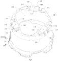
- a ventilation notch 130 is provided at a junction between a circumferential wall and the bottom wall of the outer pot 100.
- the airflow can pass through the ventilation notch 130, such that it is convenient for heat to be exhausted out of the ventilation notch 130, thereby further facilitating the heat dissipation of the outer pot 100.
- a depth h of the ventilation notch 130 in a vertical direction is less than 90 millimeters, and a width a of the ventilation notch 130 in a circumferential direction of the outer pot 100 is less than 200 millimeters, thus ensuring a capacity and a structural strength of the outer pot 100 while ensuring the heat dissipation effect of the ventilation notch 130.
- a lower end of the supporting pillar 210 has a lower supporting plane
- the support rib 110 is provided with an outer-pot supporting plane 111
- the lower supporting plane is supported on the outer-pot supporting plane 111, such that the stability of the supporting pillar 210 supported on the support rib 110 can be improved, thus improving the stability of the inner pot 300 supported on the supporting pillar 210, and thereby further improving the supporting effect with regard to the inner pot 300.
- an elastic member is provided below the supporting pillar 210, and the supporting pillar 210 is supported on the elastic member 220.
- the elastic member 220 is deformed to shorten the distance between the inner pot 300 and the outer pot 100, thereby decompressing the electric pressure cooker 1.
- the circumferential wall of the outer pot 100 is provided with a circumferential-wall reinforcing rib 141, and the bottom wall of the outer pot 100 is provided with a bottom-wall reinforcing rib 142.
- the structural strength of the outer pot 100 can be improved, so as to prevent the outer pot 100 from being deformed.
- the structural strength and the stability of the support rib 110 can be improved, so as to prevent the support rib 110 from being deformed, which otherwise will result in a displacement of the supporting pillar 210, thereby further improving the stability of the supporting pillar 210.
- the bottom-wall reinforcing rib 142 can be used to position the supporting pillar 210.
- a height of the bottom-wall reinforcing rib 142 away from the bottom wall of the outer pot 100 is less than 30 millimeters, such that a reinforcing effect of the bottom-wall reinforcing rib 142 on the outer pot 100 can be ensured.
- an inner circumferential edge of the heat dissipation opening 120 is provided with an upper turn-up 121.
- the upper turn-up 121 can be used to further improve the structural strength of the outer pot 100, so as to prevent the outer pot 100 from being deformed, and the upper turn-up 121 also can be used to block a water flow, so as to prevent the water from flowing down through the heat dissipation opening 120, thereby ensuring the reliability of the electric pressure cooker 1.
- a height of the upper turn-up 121 in the vertical direction is 1-15 millimeters, thereby facilitating the manufacturing of the upper turn-up 121 while ensuring the blocking effect of the upper turn-up 121 on the water flow.
- the support rib 110 is provided with a mounting hole 112.
- the supporting pillar 210 may be provided with a threaded hole, and the supporting pillar 210 is mounted to the support rib 110 through a screw or a bolt fitted in the mounting hole 112 and the threaded hole.
- it is convenient for fixation of the supporting pillar 210, so as to facilitate improvements of the stability and the reliability of the supporting pillar 210.
- a plurality of support ribs 110 are provided and spaced apart from each other in the circumferential direction of the outer pot 100, a plurality of supporting pillars 210 are provided and supported on the plurality of support ribs 110 correspondingly.
- the plurality of supporting pillars 210 can be used to support the inner pot 300, so as to enable the inner pot 300 and the outer pot 100 to be forced more evenly, and also to further improve the stability of the inner pot 300.
- three supporting pillars 210 are provided, thus facilitating the support for the inner pot 300, and ensuring the stability of the inner pot 300.
- the outer pot 100 is formed by stamping a cold-rolled sheet, and a thickness of the cold-rolled sheet is 0.4-2 millimeters, so as to ensure the structural strength and the rigidity of the outer pot 100.
- Fig. 1 illustrates the electric pressure cooker 1 according to a specific embodiment of the present disclosure.
- the electromagnetic heating device 400 includes the electromagnetic heating plate 410, and the projection of the electromagnetic heating plate 410 in the horizontal direction is staggered with a projection of the supporting pillar 210 in the horizontal direction.
- the electromagnetic heating plate 410 refers to a structure of the electromagnetic heating device 400 for achieving the electromagnetic heating function.
- the expression "the electromagnetic heating device 400 includes the electromagnetic heating plate 410” may indicate that the electromagnetic heating device 400 includes the electromagnetic heating plate 410 and other structures, and may also indicate that the electromagnetic heating device 400 is the electromagnetic heating plate 410.
- the projection of the electromagnetic heating plate 410 in the horizontal direction is staggered with a projection of the supporting pillar 210 in the horizontal direction
- the projection of the electromagnetic heating plate 410 in the horizontal direction and the projection of the supporting pillar 210 in the horizontal direction are not overlapped.
- the electromagnetic heating plate 410 can be arranged as close as possible to the bottom wall of the inner pot 300, so as to improve the heating effect of the electromagnetic heating plate 410 on the inner pot 300 and improve the heating efficiency of the electromagnetic heating device 400.
- the distance between the inner bottom surface of the outer pot 100 and the outer bottom surface of the inner pot 300 can be conveniently controlled, so as to leave more space for the arrangement of the electromagnetic heating device 400, thus further preventing the electromagnetic heating device 400 from being damaged under stress.
- the electric pressure cooker 1 may further include the cooker body 20 and the cooker cover 10.
- the inner pot 300, the outer pot 100, the supporting pillar 210 and the electromagnetic heating device 400 are disposed in the cooker body 20.
- an outer circumferential edge of the outer pot 100 may be provided with a plurality of outer-pot teeth
- the cooker cover 10 may be provided with a plurality of inner-pot teeth.
- the electric pressure cooker 1 includes the outer pot 100, the rigid supporting pillar 210, the inner pot 300, the electromagnetic heating device 400, a housing 600 and a fan 700.
- the housing 600 is provided with an air inlet 611 and an air outlet 612.
- the outer pot 100 is disposed in the housing 600.
- the rigid supporting pillar 210 is disposed in the outer pot 100.
- the inner pot 300 is disposed in the outer pot 100 and supported on the rigid supporting pillar 210. Under the support of the rigid supporting pillar 210, the outer bottom surface of the inner pot 300 is spaced apart from the inner bottom surface of the outer pot 100.
- the electromagnetic heating device 400 is used to heat the inner pot 300, and the electromagnetic heating device 400 is disposed between the outer bottom surface of the inner pot 300 and the inner bottom surface of the outer pot 100.
- the fan 700 is disposed between an inner surface of the housing 600 and an outer surface of the outer pot 100.
- the fan 700 can be used to convey air, such that the air enters the housing 600 through the air inlet 611 and takes the heat in the housing 600 out of the air outlet 612, so as to cool structures inside the housing 600, and ensure a reliable operation of the electric pressure cooker 1.
- a distance between the fan 700 and the bottom wall of the outer pot 100 is less than or equal to 150 millimeters, such that the fan 700 can be as close as possible to the outer pot 100, thus ensuring an air speed at the electromagnetic heating device 400, and ensuring a cooling effect on the electromagnetic heating device 400 and the outer pot 100.
- the ventilation notch 130 is provided at the junction between the circumferential wall and the bottom wall of the outer pot 100, and the ventilation notch 130 is disposed adjacent to the fan 700.
- the airflow can pass through the ventilation notch 130 into the outer pot 100, thereby further facilitating the heat dissipation of the electromagnetic heating device 400 and the outer pot 100.
- the ventilation notch 130 is communicated with the heat dissipation opening 120, such that the airflow can enter the heat dissipation opening 120 through the ventilation notch 130, thereby further facilitating the heat dissipation of the electromagnetic heating device 400 and the outer pot 100.
- the depth h of the ventilation notch 130 in the vertical direction is less than 90 millimeters, and the width a of the ventilation notch 130 in the circumferential direction of the outer pot 100 is less than 200 millimeters, thus ensuring the capacity and the structural strength of the outer pot 100 while ensuring the heat dissipation effect of the ventilation notch 130.
- Figs. 1-21 illustrate the electric pressure cooker 1 according to a specific embodiment of the present disclosure.
- the electric pressure cooker 1 further includes a power supply board 800, the power supply board 800 is located between the outer circumferential wall of the outer pot 100 and the inner circumferential wall of the housing 600, and is adjacent to the fan 700, such that the electromagnetic heating device 400 can be supplied with power through the power supply board 800, so as to facilitate the control over the electric pressure cooker 1 and the arrangements of the respective components, and also, the fan 700 can be used for the cooling and the heat dissipation of the power supply board 800, so as to ensure the reliability of the power supply board 800 during its operation.
- an end of the power supply board 800 adjacent to the fan 700 is provided with a cooling fin 810, such that the power supply board 800 can be further cooled through the cooling fin 810, thus increasing a heat dissipation area of the power supply board 800, and improving cooling and heat dissipation effects of the fan 700 on the power supply board 800.
- the power supply board 800 is oriented in the vertical direction, and the cooling fin 810 extends from the power supply board 800 to the housing 600, such that the extending direction of the cooling fin 810 is perpendicular to a blowing direction of the fan 700, thereby improving the heat dissipation effect of the fan 700 on the power supply board 800.
- a plurality of cooling fins 810 may be provided and spaced apart from each other in the horizontal direction, such that the plurality of cooling fins 810 can be used for heat dissipation, so as to enable the airflow to pass through a gap between two adjacent cooling fins 810, thus further improving the heat dissipation area and ensuring the heat dissipation effect.
- the housing 600 is provided with a wind deflector 630, the wind deflector 630 is oriented in the vertical direction and spaced apart from the cooling fin 810, such that the wind deflector 630 can be used to guide the airflow blown out by the fan 700, thus ensuring the heat dissipation effect of the fan 700.
- a distance between the wind deflector 630 and the cooling fin 810 is less than or equal to 30 millimeters, such that a resistance acted on the airflow blowing through the gap between the wind deflector 630 and the cooling fin 810 can be adjusted, so as to ensure the heat dissipation effect of the fan 700.
- Figs. 1-21 illustrate the electric pressure cooker 1 according to a specific embodiment of the present disclosure.
- the fan 700 is located above the air inlet 611, such that a distance between the air inlet 611 and the fan 700 can be shortened, and the flow speed of the air in the housing 600 is ensured, thereby ensuring the cooling effect on the electromagnetic heating device 400 and the outer pot 100.
- the housing 600 includes a base 610, the air inlet 611 and the air outlet 612 are both provided to the base 610 and respectively adjacent to two ends of the base 610, such that an appearance of the electric pressure cooker 1 is neat and aesthetic, and most part of the airflow can pass through a radial direction of the electromagnetic heating device 400, thus ensuring the cooling effect on the electromagnetic heating device 400.
- the air inlet 611 is adjacent to a front end of the base 610 and the air outlet 612 is adjacent to a rear end of the base 610 (a front and rear direction is shown by arrow B in the drawings).
- the housing 600 is provided with a supporting foot 620 at a bottom thereof, and a length of the supporting foot 620 away from a lower surface of the housing 600 is 1-75 millimeters.
- a length of the supporting foot 620 away from a lower surface of the housing 600 is 1-75 millimeters.
- the fan 700 starts operating, and the outside air enters the housing 600 through the air inlet 611, and produces an airflow in the housing 600 under the action of the fan 700.
- the wind deflector 630 most part of the airflow enters the space between the bottom wall of the outer pot 100 and the bottom wall of the inner pot 300 through the ventilation notch 130 and the heat dissipation opening 120, so as to take away the heat of the electromagnetic heating device 400 and discharge the heat out of the air outlet 612, and the rest part of the airflow blows to the power supply board 800, so as to cool the cooling fin 810.
- the electric pressure cooker 1 includes the outer pot 100, the supporting pillar 210, an elastic member 220, the inner pot 300, the electromagnetic heating device 400, the housing 600 and the fan 700.
- the housing 600 is provided with the air inlet 611 and the air outlet 612.
- the outer pot 100 is disposed in the housing 600.
- the elastic member 220 is disposed in the outer pot 100 and supported on the bottom wall of the outer pot 100.
- the supporting pillar 210 is disposed in the outer pot 100 and supported on the elastic member 220.
- the inner pot 300 is disposed in the outer pot 100 and supported on the supporting pillar 210, and the elastic member 220 is deformed when the pressure in the inner pot 300 reaches a pre-determined value, so as to release the pressure in the inner pot 300.
- the electromagnetic heating device 400 is used to heat the inner pot 300, and the electromagnetic heating device 400 is disposed between the outer bottom surface of the inner pot 300 and the inner bottom surface of the outer pot 100.
- the fan 700 is disposed between the inner surface of the housing 600 and the outer surface of the outer pot 100.
- the elastic member 220 can be deformed when the pressure in the inner pot 300 reaches the pre-determined value, so as to decompress the inner pot 300, and thus the electric pressure cooker 1 can be prevented from being damaged due to the excessively high pressure in the inner pot 300, thereby improving the reliability of the electric pressure cooker 1.
- the elastic member 220 is deformed to move the inner pot 300 downwards, when the pressure in the inner pot 300 reaches the pre-determined value.
- the pressure in the inner pot 300 is increased continuously, a force acted on the supporting pillar 210 by the inner pot 300 is increased continuously and a force acted on the elastic member 220 by the supporting pillar 210 is also increased continuously.
- the elastic member 220 is deformed under the force, so as to move the inner pot 300 downwards to release the pressure, such that the pressure relief of the inner pot 300 can be achieved, and the reliability of the electric pressure cooker 1 can be ensured.
- the electric pressure cooker 1 includes the cooker body and the cooker cover, and the cooker cover is rotatably disposed to the cooker body, so as to open or close the inner pot 300.
- a seal ring may be provided between the inner pot 300 and the cooker cover.
- the bottom wall of the outer pot 100 is provided with the reinforcing rib, two ends of the elastic member 220 are supported on the reinforcing rib respectively and the supporting pillar 210 is supported at a center of the elastic member 220 in a length direction thereof, such that it is convenient for the elastic member 220 to be deformed so as to move the supporting pillar 210 downwards, and thus it is convenient for the inner pot 300 to move downwards when the elastic member 220 is deformed.
- the reinforcing rib includes the circumferential-wall reinforcing rib 141 and the bottom-wall reinforcing rib 142.
- the circumferential wall of the outer pot 100 is provided with the circumferential-wall reinforcing rib 141, and the bottom wall of the outer pot 100 is provided with the bottom-wall reinforcing rib 142.
- the elastic member 220 may be supported on the bottom-wall reinforcing rib 142.
- the structural strength of the outer pot 100 can be improved to prevent the outer pot 100 from being deformed, and the structural strength and the stability of the bottom wall of the outer pot 100 can be improved to prevent the outer pot 100 from being plastically deformed and hence resulting in a displacement of the supporting pillar 210, so as to further improve the stability of the rigid supporting pillar 210.
- the bottom-wall reinforcing rib 142 may be used to position the rigid supporting pillar 210.
- the elastic member 220 has a plate shape and a width of the elastic member 220 is gradually increased from two ends of the elastic member 220 to the middle of the elastic member, such that it is convenient to adjust an effect of the force acted on the elastic member 220, so as to ensure that the elastic member 220 can be deformed promptly when the pressure in the inner pot 300 is excessively high, thereby ensuring the reliability of the electric pressure cooker 1.
- the lower end of the supporting pillar 210 is mounted to the elastic member 220 and an upper end of the supporting pillar 210 abuts against the outer bottom surface of the inner pot 300, thus facilitating the fixation of the rigid supporting pillar 210, and improving the stability and the reliability of the rigid supporting pillar 210.
- the supporting pillar 210 is provided with a mounting hole
- the outer pot 100 is provided with the mounting hole 112
- the elastic member 220 is provided with an elastic-member through hole
- the supporting pillar 210 is mounted to the outer pot 100 through a threaded fastener fitted in the mounting hole, the mounting hole 112 and the elastic-member through hole, such that the connection of the elastic member 220, the supporting pillar 210 and the outer pot 100 can be achieved, and the stability of relative positions among the elastic member 220, the supporting pillar 210 and the outer pot 100 can be ensured.
- the electromagnetic heating plate 410 includes a coil plate 411, a coil and a magnetic stripe 414.
- the coil plate 411 is provided with a coil slot.
- the coil is fitted in the coil slot.
- the magnetic stripe 414 is disposed to the coil plate 411.
- the coil slot may be used to position the coil, thus facilitating the mounting of the coil, and improving the stability of the coil.
- the electromagnetic heating plate 410 further includes a magnetic-stripe fixing frame 413, the magnetic-stripe fixing frame 413 is mounted to the coil plate 411, and the magnetic stripe 414 is mounted to the magnetic-stripe fixing frame 413, such that the magnetic-stripe fixing frame 413 can be used to position the magnetic stripe 414, thereby improving the stability of the magnetic stripe 414.
- the magnetic stripe 414 may be mounted to the magnetic-stripe fixing frame 413 firstly during mounting, and then the magnetic stripe 414 and the magnetic-stripe fixing frame 413 are together mounted to the coil plate 411, thereby facilitating the mounting of the magnetic stripe 414, and simplifying the assembling process of the electromagnetic heating plate 410.
- the coil plate 411 and the holder 420 are integrally molded, such that the structural strength and the connection strength of the coil plate 411 and the holder 420 can be ensured, the assembling process of the electric pressure cooker 1 can be simplified, and the production efficiency of the electric pressure cooker 1 can be improved.
- the coil plate 411 is connected to the holder 420 through a threaded fastener, such that the manufacturing difficulties of the holder 420 and the coil plate 411 can be reduced, thereby facilitating the production and manufacturing of the holder 420 and the coil plate 411.
- the magnetic-stripe fixing frame 413 is provided with a magnetic-stripe mounting groove
- the coil plate 411 is provided with a magnetic-stripe positioning groove
- the magnetic stripe 414 is provided with a positioning protrusion
- the magnetic stripe 414 is fitted in the magnetic-stripe mounting groove
- the positioning protrusion is fitted in the magnetic-stripe positioning groove.
- the magnetic-stripe positioning groove, the magnetic-stripe mounting groove and the positioning protrusion may be used to position the magnetic stripe 414, thereby facilitating the mounting of the magnetic stripe 414, and improving the stability of the magnetic stripe 414 after being mounted.
- the positioning protrusion includes an inner positioning protrusion 4141 and an outer positioning protrusion 4142 located at two ends of the magnetic stripe 414 respectively
- the magnetic-stripe positioning groove includes an inner positioning groove 4111 disposed adjacent to a center of the coil plate 411 and an outer positioning groove 4112 disposed adjacent to an outer circumferential edge of the coil plate 411
- the inner positioning protrusion 4141 is fitted in the inner positioning groove 4111
- the outer positioning protrusion 4142 is fitted in the outer positioning groove 4112, such that the two ends of the magnetic stripe 414 can be positioned respectively, thereby further ensuring the stability and reliability of the magnetic stripe 414.
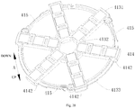
- the magnetic-stripe fixing frame 413 is provided with a plurality of magnetic-stripe positioning sleeves 4131, an inner connecting rib 4132 and an outer connecting rib 4133.
- Each magnetic-stripe positioning sleeve 4131 is provided with the magnetic-stripe mounting groove therein, inner ends of the plurality of magnetic-stripe positioning sleeves 4131 are connected and outer ends of the plurality of magnetic-stripe positioning sleeves 4131 are spaced apart from each other.
- the inner connecting rib 4132 is connected with the plurality of magnetic-stripe positioning sleeves 4131 respectively and is disposed adjacent to inner ends of the magnetic-stripe positioning sleeves 4131.
- the outer connecting rib 4133 is connected with the plurality of magnetic-stripe positioning sleeves 4131 respectively and is disposed adjacent to outer ends of the magnetic-stripe positioning sleeves 4131.
- the magnetic-stripe positioning sleeve 4131 may be provided with a consumption-reducing hole, such that it is convenient for the magnetic-stripe fixing frame 413 to be molded, a material cost of the magnetic-stripe fixing frame 413 is saved, and a stability of the magnetic-stripe fixing frame 413 is ensured, so as to ensure a fixing effect on the magnetic stripe 414.
- an outer edge of the magnetic-stripe fixing frame 413 is provided with a relief groove 415 for escaping the supporting pillar 210, such that it is convenient to arrange the supporting pillar 210 and the relief groove 415 can be used to position the supporting pillar 210, further improving the stability of the supporting pillar 210 and the electromagnetic heating plate 410.
- an upper surface of the holder 420 is provided with a decoration cover 500
- the decoration cover 500 is provided with a through hole 510 for escaping the supporting pillar 210.
- the decoration cover 500 may be provided with a pattern constituted by a protrusion and/or a depression.
- the decoration cover 500 may be used to decorate a top surface of the holder 420, such that an interior of the electric pressure cooker 1 is allowed to be more aesthetic when the inner pot 300 is taken out by the user.
- the through hole 510 is provided to the decoration cover 500, the supporting pillar 210 can be escaped, such that the supporting pillar 210 can support the inner pot 300 directly, thus preventing the decoration cover 500 from being pressured and damaged.
- the supporting pillar 210 and the holder 420 are integrally molded, thereby simplifying the assembling process of the electric pressure cooker 1 and improving the production efficiency of the electric pressure cooker 1.
- the supporting pillar 210 may be embedded and injection-molded to the holder 420, thereby achieving the mounting of the supporting pillar 210 as well.
- the supporting pillar 210 is mounted to the outer pot 100 through a screw or a bolt, thereby improving the stability of the supporting pillar 210.
- a temperature-controller mounting hole 422 may be provided at a center of the bolder 420, such that a temperature controller may be mounted in the temperature-controller mounting hole 422, so as to detect a temperature in the inner pot 300.
- the outer pot 100 may be an elastic part.
- the supporting pillar 210 may be used to support the inner pot 300.
- the bottom wall of the outer pot 100 is deformed to move the inner pot 300 downwards, thereby releasing the pressure in the electric pressure cooker 1.
- first and second are used herein for purposes of description and are not intended to indicate or imply relative importance or significance or to imply the number of indicated technical features.
- the feature defined with “first” and “second” may comprise one or more of this feature.
- a plurality of' means two or more than two, unless specified otherwise.
- the terms “mounted,” “connected,” “coupled,” “fixed” and the like are used broadly, and may be, for example, fixed connections, detachable connections, or integral connections; may also be mechanical or electrical connections; may also be direct connections or indirect connections via intervening structures; may also be inner communications of two elements, which can be understood by those skilled in the art according to specific situations.
- a structure in which a first feature is "on" or “below” a second feature may include an embodiment in which the first feature is in direct contact with the second feature, and may also include an embodiment in which the first feature and the second feature are not in direct contact with each other, but are contacted via an additional feature formed therebetween.
- a first feature "on,” “above,” or “on top of' a second feature may include an embodiment in which the first feature is right or obliquely “on,” “above,” or “on top of' the second feature, or just means that the first feature is at a height higher than that of the second feature; while a first feature "below,” “under,” or “on bottom of' a second feature may include an embodiment in which the first feature is right or obliquely “below,” “under,” or “on bottom of' the second feature, or just means that the first feature is at a height lower than that of the second feature.
Landscapes
- Engineering & Computer Science (AREA)
- Food Science & Technology (AREA)
- Cookers (AREA)
Abstract
Description
- The present disclosure relates to a technical field of electric appliance manufacturing, and more particularly to an electric pressure cooker.
- In a pressure cooker in the related art, an electric heating plate having a heating tube is provided to an outer pot so as to heat an inner pot. Adopting this heating method causes a very high thermal inertia and a poor controllability in temperature and pressure, thus resulting in a low pressure control precision of the pressure cooker, and hence influencing a cooking effect.
- Embodiments of the present disclosure seek to solve at least one of the problems existing in the related art to at least some extent. For this reason, the present disclosure provides an electric pressure cooker, which has advantages of a low thermal inertia, a good controllability, a high production efficiency, a good heating effect and a high reliability.
- To achieve the above objective, an electric pressure cooker is provided according to embodiments of the present disclosure. The electric pressure cooker includes an outer pot provided with a support rib at a lower end of the outer pot; a supporting member disposed in the outer pot and supported on the support rib; an inner pot disposed in the outer pot and supported on the supporting member, and an outer bottom surface of the inner pot being spaced apart from an inner bottom surface of the outer pot, under support of the supporting member; and an electromagnetic heating device configured to heat the inner pot, and disposed between the outer bottom surface of the inner pot and the inner bottom surface of the outer pot.
- The electric pressure cooker according to embodiments of the present disclosure has advantages of a low thermal inertia, a good controllability, a high production efficiency, a good heating effect and a high reliability.
- In addition, the electric pressure cooker according to the above embodiments of the present disclosure may have following additional technical features.
- According to an embodiment of the present disclosure, the supporting member is configured as a rigid supporting member.
- According to an embodiment of the present disclosure, the rigid supporting member includes a plurality of supporting pillars arranged along a circumferential direction of the inner pot and spaced apart from one another.
- According to an embodiment of the present disclosure, an outer circumferential edge of the outer bottom surface of the inner pot is supported on the plurality of supporting pillars.
- According to an embodiment of the present disclosure, the rigid supporting member further includes a connecting ring extending in the circumferential direction of the inner pot and respectively connected with the plurality of supporting pillars, and the electromagnetic heating device is fitted in the connecting ring.
- According to an embodiment of the present disclosure, the plurality of supporting pillars are connected to a lower surface of the connecting ring, and the inner pot is supported on the connecting ring.
- According to an embodiment of the present disclosure, the rigid supporting member is configured as an annular supporting boss extending in the circumferential direction of the inner pot, and the electromagnetic heating device is fitted in the annular supporting boss.
- According to an embodiment of the present disclosure, an inner bottom wall of the outer pot is provided with a supporting-member positioning groove, and the rigid supporting member is fitted in the supporting-member positioning groove.
- According to an embodiment of the present disclosure, the electric pressure cooker further includes a fan, the housing is provided with an air inlet and an air outlet, and the fan is disposed between an inner surface of the housing and an outer surface of the outer pot.
- According to an embodiment of the present disclosure, a bottom wall of the outer pot is provided with a heat dissipation opening, and the fan is disposed between the bottom wall of the outer pot and a bottom wall of the housing.
- According to an embodiment of the present disclosure, a sectional area of the heat dissipation opening is larger than 1500 square millimeters.
- According to an embodiment of the present disclosure, a ventilation notch is provided at a junction between a circumferential wall and a bottom wall of the outer pot.
- According to an embodiment of the present disclosure, a depth of the ventilation notch in a vertical direction is less than 90 millimeters, and a width of the ventilation notch in a circumferential direction of the outer pot is less than 200 millimeters.
- According to an embodiment of the present disclosure, a distance between the fan and the bottom wall of the outer pot is less than or equal to 150 millimeters.
- According to an embodiment of the present disclosure, the electric pressure cooker further includes a power supply board, the power supply board is located between an outer circumferential wall of the outer pot and an inner circumferential wall of the housing and is arranged adjacent to the fan.
- According to an embodiment of the present disclosure, an end of the power supply board adjacent to the fan is provided with a cooling fin.
- According to an embodiment of the present disclosure, the power supply board is oriented in the vertical direction, and the cooling fin extends from the power supply board to the housing.
- According to an embodiment of the present disclosure, the housing is provided with a wind deflector, the wind deflector is oriented in the vertical direction and spaced apart from the cooling fin.
- According to an embodiment of the present disclosure, a distance between the wind deflector and the cooling fin is less than or equal to 30 millimeters.
- According to an embodiment of the present disclosure, the fan is located above the air inlet.
- According to an embodiment of the present disclosure, the housing includes a base, the air inlet and the air outlet both are provided to the base and respectively adjacent to two ends of the base.
- According to an embodiment of the present disclosure, the housing is provided with a supporting foot at a bottom thereof, and a length of the supporting foot away from a lower surface of the housing is 1-75 millimeters.
- According to an embodiment of the present disclosure, an inner circumferential edge of the heat dissipation opening is provided with an upper turn-up.
- According to an embodiment of the present disclosure, a height of the upper turn-up in the vertical direction is 1-15 millimeters.
- According to an embodiment of the present disclosure, an elastic member is provided below the supporting member, and the supporting member is supported on the elastic member.
- According to an embodiment of the present disclosure, the elastic member is configured to be deformed when a pressure in the inner pot reaches a pre-determined value, so as to release the pressure in the inner pot.
- According to an embodiment of the present disclosure, the elastic member is configured to be deformed to move the inner pot downwards when the pressure in the inner pot reaches the pre-determined value.
- According to an embodiment of the present disclosure, the circumferential wall of the outer pot is provided with a circumferential-wall reinforcing rib, the bottom wall of the outer pot is provided with a bottom-wall reinforcing rib, two ends of the elastic member are respectively supported on the bottom-wall reinforcing rib and the supporting member is supported at a center of the elastic member in a length direction of the elastic member.
- According to an embodiment of the present disclosure, the elastic member has a plate shape and a width of the elastic member is gradually increased from two ends of the elastic member to a middle of the elastic member.
- According to an embodiment of the present disclosure, the supporting member is provided with a mounting hole, the outer pot is provided with an outer-pot through hole, the elastic member is provided with an elastic-member through hole, and the supporting member is mounted to the outer pot through a threaded fastener fitted in the mounting hole, the outer-pot through hole and the elastic-member through hole.
- According to an embodiment of the present disclosure, a height of the bottom-wall reinforcing rib away from the bottom wall of the outer pot is less than 30 millimeters.
- According to an embodiment of the present disclosure, the outer pot is formed by stamping a cold-rolled sheet, and a thickness of the cold-rolled sheet is 0.4-2 millimeters.
- According to an embodiment of the present disclosure, the electromagnetic heating device includes an electromagnetic heating plate, and a projection of the electromagnetic heating plate in a horizontal direction is staggered with a projection of the supporting member in the horizontal direction.
- According to an embodiment of the present disclosure, the electromagnetic heating plate is spaced apart from at least one of the inner bottom surface of the outer pot and the outer bottom surface of the inner pot.
- According to an embodiment of the present disclosure, the electromagnetic heating plate is spaced apart from the inner bottom surface of the outer pot and the outer bottom surface of the inner pot respectively, and is more adjacent to the outer bottom surface of the inner pot with respect to the inner bottom surface of the outer pot.
- According to an embodiment of the present disclosure, the electromagnetic heating device further includes a holder, the holder is disposed between the outer bottom surface of the inner pot and the inner bottom surface of the outer pot, the supporting member is disposed to the holder, and the electromagnetic heating plate is provided to the holder.
- According to an embodiment of the present disclosure, the holder is provided with mounting holes spaced apart from one another in a circumferential direction of the holder, and the supporting member is fitted in the mounting hole.
- According to an embodiment of the present disclosure, the electromagnetic heating plate includes; a coil plate provided with a coil slot therein; a coil fitted in the coil slot; and a magnetic stripe disposed to the coil plate.
- According to an embodiment of the present disclosure, the electromagnetic heating plate further includes a magnetic-stripe fixing frame, the magnetic-stripe fixing frame is mounted to the coil plate, and the magnetic stripe is mounted to the magnetic-stripe fixing frame.
- According to an embodiment of the present disclosure, the coil plate and the holder are integrally molded.
- According to an embodiment of the present disclosure, the coil plate is connected to the holder through a threaded fastener.
- According to an embodiment of the present disclosure, the magnetic-stripe fixing frame is provided with a magnetic-stripe mounting groove, the coil plate is provided with a magnetic-stripe positioning groove, the magnetic stripe is provided with a positioning protrusion, the magnetic stripe is fitted in the magnetic-stripe mounting groove and the positioning protrusion is fitted in the magnetic-stripe positioning groove.
- According to an embodiment of the present disclosure, the positioning protrusion includes an inner positioning protrusion and an outer positioning protrusion respectively located at two ends of the magnetic stripe, the magnetic-stripe positioning groove includes an inner positioning groove disposed adjacent to a center of the coil plate and an outer positioning groove disposed adjacent to an outer circumferential edge of the coil plate, the inner positioning protrusion is fitted in the inner positioning groove and the outer positioning protrusion is fitted in the outer positioning groove.
- According to an embodiment of the present disclosure, an outer edge of the magnetic-stripe fixing frame is provided with a relief groove for escaping the supporting member.
- According to an embodiment of the present disclosure, an upper surface of the holder is provided with a decoration cover, and the decoration cover is provided with a through hole for escaping the supporting member.
-
-
Fig. 1 is a sectional view of an electric pressure cooker according to embodiments of the present disclosure. -
Fig. 2 is a schematic view of a supporting member and an electromagnetic heating device of an electric pressure cooker according to a specific embodiment of the present disclosure. -
Fig. 3 is a schematic view of a supporting member and an electromagnetic heating device of an electric pressure cooker according to another specific embodiment of the present disclosure. -
Fig. 4 is a schematic view of a supporting member of an electric pressure cooker according to another specific embodiment of the present disclosure. -
Fig. 5 is a schematic view of a supporting member of an electric pressure cooker according to another specific embodiment of the present disclosure. -
Fig. 6 is a schematic view of a supporting pillar of a supporting member of an electric pressure cooker according to another specific embodiment of the present disclosure. -
Fig. 7 is a schematic view of an outer pot of an electric pressure cooker according to embodiments of the present disclosure. -
Fig. 8 is a schematic view of an outer pot of an electric pressure cooker according to embodiments of the present disclosure. -
Fig. 9 is a sectional view of an outer pot of an electric pressure cooker according to embodiments of the present disclosure. -
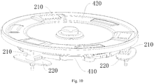
Fig. 10 is a partial schematic view of an electric pressure cooker according to embodiments of the present disclosure. -
Fig. 11 is a sectional view of an electric pressure cooker according to embodiments of the present disclosure. -
Fig. 12 is a schematic view of an electric pressure cooker according to embodiments of the present disclosure. -
Fig. 13 is a partial schematic view of an electric pressure cooker according to embodiments of the present disclosure. -
Fig. 14 is a partial schematic view of an electric pressure cooker according to embodiments of the present disclosure. -
Fig. 15 is a schematic view of an outer pot of an electric pressure cooker according to embodiments of the present disclosure. -
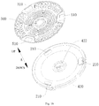
Fig. 16 is an exploded view of an electric pressure cooker according to embodiments of the present disclosure. -
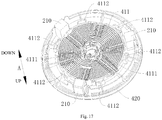
Fig. 17 is a partial schematic view of an electric pressure cooker according to embodiments of the present disclosure. -
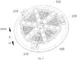
Fig. 18 is an exploded view of an electric pressure cooker according to embodiments of the present disclosure. -
Fig. 19 is a partial schematic view of an electric pressure cooker according to embodiments of the present disclosure. -
Fig. 20 is a schematic view of a magnetic-stripe fixing frame and a magnetic stripe of an electric pressure cooker according to embodiments of the present disclosure. -
Fig. 21 is a schematic view of a magnetic-stripe fixing frame and a magnetic stripe of an electric pressure cooker according to embodiments of the present disclosure. -
Electric pressure cooker 1,cooker cover 10,cooker body 20,outer pot 100,support rib 110, outer-pot supporting plane 111, mountinghole 112,heat dissipation opening 120, upper turn-up 121,ventilation notch 130, circumferential-wall reinforcing rib 141, bottom-wall reinforcing rib 142, supportingmember 200, supportingpillar 210, connectingring 220, annular supportingboss 230,inner pot 300,electromagnetic heating device 400,electromagnetic heating plate 410,coil plate 411,inner positioning groove 4111,outer positioning groove 4112, the coil, magnetic-stripe fixing frame 413, magnetic-stripe positioning sleeve 4131, inner connectingrib 4132, outer connectingrib 4133,magnetic stripe 414,inner positioning protrusion 4141,outer positioning protrusion 4142,relief groove 415,holder 420, temperature-controller mounting hole 422,decoration cover 500, throughhole 510,housing 600,base 610,air inlet 611,air outlet 612, supportingfoot 620,wind deflector 630,fan 700,power supply board 800, coolingfin 810. - Embodiments of the present disclosure will be elaborated in below and examples of the embodiments are illustrated in the drawings. The same or similar elements and the elements having same or similar functions are denoted by like reference numerals throughout the descriptions. The embodiments described herein with reference to drawings are explanatory and used to generally understand the present disclosure. The embodiments shall not be construed to limit the present disclosure.
- An
electric pressure cooker 1 according to embodiments of the present disclosure will be described in detail with reference to the drawings. - As illustrated in the drawings, the
electric pressure cooker 1 according to embodiments of the present disclosure includes anouter pot 100, a supportingmember 200, aninner pot 300 and anelectromagnetic heating device 400. - A lower end of the
outer pot 100 is provided with a support rib 110 (an up and down direction is shown by arrow A inFigs. 1-4 ). The supportingmember 200 is disposed in theouter pot 100 and supported on thesupport rib 110. Theinner pot 300 is disposed in theouter pot 100 and supported on the supportingmember 200. Under support of the supportingmember 200, an outer bottom surface of theinner pot 300 is spaced apart from an inner bottom surface of theouter pot 100. Theelectromagnetic heating device 400 is used for heating theinner pot 300, and theelectromagnetic heating device 400 is disposed between the outer bottom surface of theinner pot 300 and the inner bottom surface of theouter pot 100. - For the
electric pressure cooker 1 according to embodiments of the present disclosure, by arranging theelectromagnetic heating device 400, theinner pot 300 can be electromagnetically heated by theelectromagnetic heating device 400. Compared with the method of using an electric heating plate to heat in the related art, the electromagnetic heating can reduce a thermal inertia, make it convenient to control the temperature, and improve a control precision over the temperature and pressure, thereby improving a cooking effect of theelectric pressure cooker 1. - In addition, by arranging the
support rib 110 at the lower end of theouter pot 100, the supportingmember 200 can be supported on thesupport rib 110, such that the supportingmember 200 can be conveniently supported on theouter pot 10, so as to ensure an supporting effect of the supportingmember 200 on theinner pot 300, and a bottom wall of theouter pot 100 can be conveniently processed, for example the bottom wall of theouter pot 100 is opened, so as to facilitate heat dissipation. - Moreover, by arranging the supporting
member 200, the supportingmember 200 can be used to support theinner pot 300. When theelectric pressure cooker 1 operates, a pressure in theinner pot 300 is increased to produce a downward thrust. Under the support of the supportingmember 200, a force acted on theinner pot 300 is transmitted to theouter pot 100 through the supportingmember 200. Since the supportingmember 200 is supported between theinner pot 300 and theouter pot 100, the outer bottom surface of theinner pot 300 and the inner bottom surface of theouter pot 100 can be kept apart from each other, when theelectric pressure cooker 1 operates, so as to prevent theinner pot 300 and theouter pot 100 from squeezing theelectromagnetic heating device 400, thereby preventing theelectromagnetic heating device 400 from being damaged and improving the reliability of theelectromagnetic heating device 400. - Furthermore, by allowing a projection of an
electromagnetic heating plate 410 of theelectromagnetic heating device 400 in a horizontal direction to be staggered with a projection of the supportingmember 200 in the horizontal direction, the supportingmember 200 can escape theelectromagnetic heating plate 410, such that the supportingmember 200 is prevented from hindering the arrangement of theelectromagnetic heating plate 410, and theelectromagnetic heating plate 410 and the bottom wall of theinner pot 300 will not be blocked by the supportingmember 200 therebetween. In this way, theelectromagnetic heating plate 410 can be arranged as close as possible to the bottom wall of theinner pot 300, so as to improve a heating effect of theelectromagnetic heating plate 410 on theinner pot 300 and improve the heating efficiency of theelectromagnetic heating device 400. Moreover, a distance between the inner bottom surface of theouter pot 100 and the outer bottom surface of theinner pot 300 can be conveniently controlled, leaving more space for the arrangement of theelectromagnetic heating device 400, furthermore preventing theelectromagnetic heating device 400 from being damaged under stress. - Therefore, the
electric pressure cooker 1 according to embodiments of the present disclosure has advantages of a low thermal inertia, a good controllability, a high production efficiency, a good heating effect and a high reliability. - The
electric pressure cooker 1 according to embodiments of the present disclosure will be described in detail with reference to the drawings. - In some specific embodiments of the present disclosure, as illustrated in the drawings, the
electric pressure cooker 1 according to embodiments of the present disclosure includes theouter pot 100, the supportingmember 200, theinner pot 300 and theelectromagnetic heating device 400. - In a specific embodiment of the present disclosure, a supporting
pillar 210 is a rigid supporting member. The supportingmember 200 is disposed in theouter pot 100. Theinner pot 300 is disposed in theouter pot 100 and supported on the supportingmember 200. Under support of the supportingmember 200, the outer bottom surface of theinner pot 300 is spaced apart from the inner bottom surface of theouter pot 100. Theelectromagnetic heating device 400 is used for heating theinner pot 300, and theelectromagnetic heating device 400 is disposed between the outer bottom surface of theinner pot 300 and the inner bottom surface of theouter pot 100. Theelectromagnetic heating device 400 includes theelectromagnetic heating plate 410, and the projection of theelectromagnetic heating plate 410 in the horizontal direction is staggered with the projection of the supportingmember 200 in the horizontal direction. It should be understood that, theelectromagnetic heating plate 410 refers to a structure of theelectromagnetic heating device 400 for achieving the electromagnetic heating function. The expression "theelectromagnetic heating device 400 includes theelectromagnetic heating plate 410" may indicate that theelectromagnetic heating device 400 includes theelectromagnetic heating plate 410 and other structures, and may also indicate that theelectromagnetic heating device 400 is theelectromagnetic heating plate 410. The expression "the projection of theelectromagnetic heating plate 410 in the horizontal direction is staggered with the projection of the supportingmember 200 in the horizontal direction" indicates that the projection of theelectromagnetic heating plate 410 in the horizontal direction and the projection of the supportingmember 200 in the horizontal direction are not overlapped. - Moreover, by arranging the rigid supporting
member 200 to support theinner pot 300, compared with the method of using an elastic member to support theinner pot 300, it can be avoided that an elastic force of the elastic member is reduced or even fails due to a long time service or an excessive pressure, and since theinner pot 300 and theouter pot 100 will not produce a relative movement, a space for compressing the elastic member does not need to be reserved between theouter pot 100 and theinner pot 300, such that, on one hand, it is convenient to control a dimension of theelectric pressure cooker 1, and on the other hand, theelectromagnetic heating device 400 can be further avoided from being damaged under stress. Due to a structural limit of the elastic member itself, other rigid structures are needed to connect and position the elastic member, such that the arrangement of the supportingmember 200 can omit the structures for connecting and positioning the elastic member, thus reducing the amount of parts of theelectric pressure cooker 1, simplifying the structure of theelectric pressure cooker 1, and improving the production efficiency of theelectric pressure cooker 1. - In some specific embodiments of the present disclosure, as illustrated in the drawings, the
electric pressure cooker 1 according to embodiments of the present disclosure includes theouter pot 100, the supportingmember 200, theinner pot 300 and theelectromagnetic heating device 400. - The lower end of the
outer pot 100 is provided with thesupport rib 110. The bottom wall of theouter pot 100 is provided with aheat dissipation opening 120, and thesupport rib 110 is formed to an inner circumferential wall of theheat dissipation opening 120. Specifically, theheat dissipation opening 120 may be substantially triangle-shaped. Thus, an airflow can pass through theheat dissipation opening 120, so as to cool theouter pot 100 conveniently, and also the heating of theelectromagnetic heating device 400 on the bottom of theouter pot 100 can be reduced, thereby further facilitating the cooling and the heat dissipation of theouter pot 100. It could be understood by those skilled in the art that, thesupport rib 110 can be constituted by a portion of the bottom wall of theouter pot 100 apart from theheat dissipation opening 120. - The
electromagnetic heating plate 410 is spaced apart from at least one of the inner bottom surface of theouter pot 100 and the outer bottom surface of theinner pot 300. Thus, it is convenient for theelectromagnetic heating device 400 to be arranged, and also theelectromagnetic heating device 400 can be further prevented from being damaged due to squeeze of theouter pot 100 and theinner pot 300. - Advantageously, as illustrated in the drawings, the supporting
member 200 includes a plurality of supportingpillars 210 arranged along a circumferential direction of theinner pot 300 and spaced apart from each other. Specifically, the plurality of supportingpillars 210 are arranged at equal intervals while surrounding theelectromagnetic heating plate 410. Thus, the plurality of supportingpillars 210 can be used to support theinner pot 300, so that it is convenient to support theinner pot 300, and also to transmit the force acted on theinner pot 300 to theouter pot 100 by means of the supportingmember 200. - Specifically, as illustrated in the drawings, three supporting
pillars 210 may be provided, thus facilitating the support for theinner pot 300 and ensuring the stability of theinner pot 300. - Advantageously, as illustrated in the drawings, an outer circumferential edge of the outer bottom surface of the
inner pot 300 is supported on the plurality of supportingpillars 210. Thus, it is further convenient to support theinner pot 300, so as to improve the stability of theinner pot 300, and more space can be reserved for theelectromagnetic heating plate 410 to be mounted, such that, on one hand, it is convenient to mount theelectromagnetic heating plate 410, and on the other hand, it is beneficial to the dimension improvement of theelectromagnetic heating plate 410, so as to ensure that theinner pot 300 can be heated evenly. - In one specific embodiment of the present disclosure, as illustrated in the drawings, the
electromagnetic heating device 400 further includes aholder 420, theelectromagnetic heating plate 410 is provided to theholder 420, theholder 420 is provided with a plurality of mounting holes, and the plurality of supportingpillars 210 are fitted in the plurality of mounting holes correspondingly. It should be understood that, theholder 420 may be spaced apart from theinner pot 300 or may be fitted closely with theinner pot 300, but theholder 420 is used for positioning theelectromagnetic heating plate 410, rather than supporting theinner pot 300. Specifically, theelectromagnetic heating plate 410 is disposed to a lower surface of theholder 420, which thus facilitates the positioning of the supportingpillar 210 and theelectromagnetic heating device 400, so as to facilitate the mounting of the supportingpillar 210 and theelectromagnetic heating device 400, and also avoids the supportingpillar 210 from producing a force component when being pressured, so as to improve the stability of the supportingmember 200. - In another specific embodiment of the present disclosure, as illustrated in the drawings, the supporting
member 200 further includes a connectingring 220 extending in the circumferential direction of theinner pot 300 and respectively connected with the plurality of supportingpillars 210, and theelectromagnetic heating device 400 is fitted in the connectingring 220. Thus, it is convenient for the positioning of the plurality of supportingpillars 210 and theelectromagnetic heating device 400, so as to facilitate the mounting of the supportingmember 200, and also the supportingpillar 210 can be avoided from producing a force component when being pressured, so as to improve the stability of the supportingmember 200. - Specifically, the supporting
pillar 210 and the connectingring 220 may be integrally molded. - Optionally, as illustrated in the drawings, the plurality of supporting
pillars 210 are connected to a lower surface of the connectingring 220, and theinner pot 300 is supported on the connectingring 220. Thus, it is further beneficial to the support for theinner pot 300, so as to enable theinner pot 300 to be forced more evenly, thereby further improving the stability of theinner pot 300. - In another specific embodiment of the present disclosure, as illustrated in the drawings, the supporting
member 200 is an annular supportingboss 230 extending in the circumferential direction of theinner pot 300, and theelectromagnetic heating device 400 is fitted in the annular supportingboss 230. Thus, the annular supportingmember 200 can be used to support theinner pot 300, so as to enable theinner pot 300 and theouter pot 100 to be forced evenly and improve the stability of theinner pot 300. Moreover, theouter pot 100 or theinner pot 300 can be avoided from producing a plastic deformation and even being damaged due to an excessive partial pressure, thereby further improving the stability of theelectric pressure cooker 1. -
Fig. 1 illustrates anelectric pressure cooker 1 according to a specific embodiment of the present disclosure. As illustrated inFig. 1 , an inner bottom wall of theouter pot 100 is provided with a supporting-member positioning groove, and the supportingmember 200 is fitted in the supporting-member positioning groove. Thus, it is further convenient to position the supportingmember 200, thereby facilitating the mounting of the supportingmember 200. - Optionally, as illustrated in
Fig. 1 , the supportingmember 200 is mounted to theouter pot 100 by a threaded fastener. Thus, the mounting strength of the supportingmember 200 can be improved, and also the stability of the supportingmember 200 can be enhanced. - Specifically, as illustrated in
Fig. 1 , theelectromagnetic heating plate 410 is an electromagnetic coil plate. Specifically, the lower surface of theholder 420 can be provided with a plurality of wire-winding slots, and the electromagnetic coil plate is coiled in the wire-winding slots, thereby making it convenient to achieve the electromagnetic heating of theinner pot 300. - Specifically, as illustrated in
Fig. 1 , theelectric pressure cooker 1 can further include acooker body 20 and acooker cover 10. Theinner pot 300, theouter pot 100, the supportingmember 200 and theelectromagnetic heating device 400 are disposed in thecooker body 20. - In some specific embodiments of the present disclosure, the bottom wall of the
outer pot 100 is provided with theheat dissipation opening 120, and thesupport rib 110 is formed to the inner circumferential wall of theheat dissipation opening 120. Specifically, theheat dissipation opening 120 may be substantially triangle-shaped. Thus, the airflow can pass through theheat dissipation opening 120, so as to cool theouter pot 100, and also the heating of theelectromagnetic heating device 400 on the bottom of theouter pot 100 can be reduced, thereby further facilitating the cooling and the heat dissipation of theouter pot 100. - Optionally, a sectional area of the
heat dissipation opening 120 is larger than 1500 square millimeter, thereby ensuring a heat dissipation effect of theouter pot 100. - It could be understood by those skilled in the art that, the
support rib 110 can be constituted by the portion of the bottom wall of theouter pot 100 apart from theheat dissipation opening 120. - Advantageously, as illustrated in the drawings, a
ventilation notch 130 is provided at a junction between a circumferential wall and the bottom wall of theouter pot 100. Thus, the airflow can pass through theventilation notch 130, such that it is convenient for heat to be exhausted out of theventilation notch 130, thereby further facilitating the heat dissipation of theouter pot 100. - More advantageously, as illustrated in the drawings, a depth h of the
ventilation notch 130 in a vertical direction is less than 90 millimeters, and a width a of theventilation notch 130 in a circumferential direction of theouter pot 100 is less than 200 millimeters, thus ensuring a capacity and a structural strength of theouter pot 100 while ensuring the heat dissipation effect of theventilation notch 130. - Further, as illustrated in the drawings, a lower end of the supporting
pillar 210 has a lower supporting plane, thesupport rib 110 is provided with an outer-pot supporting plane 111, and the lower supporting plane is supported on the outer-pot supporting plane 111, such that the stability of the supportingpillar 210 supported on thesupport rib 110 can be improved, thus improving the stability of theinner pot 300 supported on the supportingpillar 210, and thereby further improving the supporting effect with regard to theinner pot 300. - In another specific embodiment of the present disclosure, an elastic member is provided below the supporting
pillar 210, and the supportingpillar 210 is supported on theelastic member 220. When a pressure exerted on theelastic member 220 reaches a pre-determined value, theelastic member 220 is deformed to shorten the distance between theinner pot 300 and theouter pot 100, thereby decompressing theelectric pressure cooker 1. - Specifically, as illustrated in the drawings, the circumferential wall of the
outer pot 100 is provided with a circumferential-wall reinforcing rib 141, and the bottom wall of theouter pot 100 is provided with a bottom-wall reinforcing rib 142. Thus, the structural strength of theouter pot 100 can be improved, so as to prevent theouter pot 100 from being deformed. Moreover, the structural strength and the stability of thesupport rib 110 can be improved, so as to prevent thesupport rib 110 from being deformed, which otherwise will result in a displacement of the supportingpillar 210, thereby further improving the stability of the supportingpillar 210. Furthermore, the bottom-wall reinforcing rib 142 can be used to position the supportingpillar 210. - More specifically, a height of the bottom-
wall reinforcing rib 142 away from the bottom wall of theouter pot 100 is less than 30 millimeters, such that a reinforcing effect of the bottom-wall reinforcing rib 142 on theouter pot 100 can be ensured. - In some specific embodiments of the present disclosure, an inner circumferential edge of the
heat dissipation opening 120 is provided with an upper turn-up 121. Thus, the upper turn-up 121 can be used to further improve the structural strength of theouter pot 100, so as to prevent theouter pot 100 from being deformed, and the upper turn-up 121 also can be used to block a water flow, so as to prevent the water from flowing down through theheat dissipation opening 120, thereby ensuring the reliability of theelectric pressure cooker 1. - Optionally, a height of the upper turn-
up 121 in the vertical direction is 1-15 millimeters, thereby facilitating the manufacturing of the upper turn-up 121 while ensuring the blocking effect of the upper turn-up 121 on the water flow. - Specifically, as illustrated in the drawings, the
support rib 110 is provided with a mountinghole 112. Specifically, the supportingpillar 210 may be provided with a threaded hole, and the supportingpillar 210 is mounted to thesupport rib 110 through a screw or a bolt fitted in the mountinghole 112 and the threaded hole. Thus, it is convenient for fixation of the supportingpillar 210, so as to facilitate improvements of the stability and the reliability of the supportingpillar 210. - Advantageously, as illustrated in the drawings, a plurality of
support ribs 110 are provided and spaced apart from each other in the circumferential direction of theouter pot 100, a plurality of supportingpillars 210 are provided and supported on the plurality ofsupport ribs 110 correspondingly. Thus, the plurality of supportingpillars 210 can be used to support theinner pot 300, so as to enable theinner pot 300 and theouter pot 100 to be forced more evenly, and also to further improve the stability of theinner pot 300. - Specifically, as illustrated in the drawings, three supporting
pillars 210 are provided, thus facilitating the support for theinner pot 300, and ensuring the stability of theinner pot 300. - More advantageously, the
outer pot 100 is formed by stamping a cold-rolled sheet, and a thickness of the cold-rolled sheet is 0.4-2 millimeters, so as to ensure the structural strength and the rigidity of theouter pot 100. -
Fig. 1 illustrates theelectric pressure cooker 1 according to a specific embodiment of the present disclosure. As illustrated in the drawings, theelectromagnetic heating device 400 includes theelectromagnetic heating plate 410, and the projection of theelectromagnetic heating plate 410 in the horizontal direction is staggered with a projection of the supportingpillar 210 in the horizontal direction. It should be understood that, theelectromagnetic heating plate 410 refers to a structure of theelectromagnetic heating device 400 for achieving the electromagnetic heating function. The expression "theelectromagnetic heating device 400 includes theelectromagnetic heating plate 410" may indicate that theelectromagnetic heating device 400 includes theelectromagnetic heating plate 410 and other structures, and may also indicate that theelectromagnetic heating device 400 is theelectromagnetic heating plate 410. The expression "the projection of theelectromagnetic heating plate 410 in the horizontal direction is staggered with a projection of the supportingpillar 210 in the horizontal direction" indicates that the projection of theelectromagnetic heating plate 410 in the horizontal direction and the projection of the supportingpillar 210 in the horizontal direction are not overlapped. By allowing the projection of theelectromagnetic heating plate 410 of theelectromagnetic heating device 400 in the horizontal direction to be staggered with the projection of the supportingpillar 210 in the horizontal direction, the supportingpillar 210 can escape theelectromagnetic heating plate 410, such that the supportingpillar 210 is prevented from hindering the arrangement of theelectromagnetic heating plate 410, and theelectromagnetic heating plate 410 and the bottom wall of theinner pot 300 will not be blocked by the supportingpillar 210 therebetween. In this way, theelectromagnetic heating plate 410 can be arranged as close as possible to the bottom wall of theinner pot 300, so as to improve the heating effect of theelectromagnetic heating plate 410 on theinner pot 300 and improve the heating efficiency of theelectromagnetic heating device 400. Moreover, the distance between the inner bottom surface of theouter pot 100 and the outer bottom surface of theinner pot 300 can be conveniently controlled, so as to leave more space for the arrangement of theelectromagnetic heating device 400, thus further preventing theelectromagnetic heating device 400 from being damaged under stress. - Specifically, as illustrated in the drawings, the
electric pressure cooker 1 may further include thecooker body 20 and thecooker cover 10. Theinner pot 300, theouter pot 100, the supportingpillar 210 and theelectromagnetic heating device 400 are disposed in thecooker body 20. - In some specific embodiments of the present disclosure, an outer circumferential edge of the
outer pot 100 may be provided with a plurality of outer-pot teeth, and thecooker cover 10 may be provided with a plurality of inner-pot teeth. - In some specific embodiments of the present disclosure, as illustrated in the drawings, the
electric pressure cooker 1 according to embodiments of the present disclosure includes theouter pot 100, the rigid supportingpillar 210, theinner pot 300, theelectromagnetic heating device 400, ahousing 600 and afan 700. - The
housing 600 is provided with anair inlet 611 and anair outlet 612. Theouter pot 100 is disposed in thehousing 600. The rigid supportingpillar 210 is disposed in theouter pot 100. Theinner pot 300 is disposed in theouter pot 100 and supported on the rigid supportingpillar 210. Under the support of the rigid supportingpillar 210, the outer bottom surface of theinner pot 300 is spaced apart from the inner bottom surface of theouter pot 100. Theelectromagnetic heating device 400 is used to heat theinner pot 300, and theelectromagnetic heating device 400 is disposed between the outer bottom surface of theinner pot 300 and the inner bottom surface of theouter pot 100. Thefan 700 is disposed between an inner surface of thehousing 600 and an outer surface of theouter pot 100. - In addition, by providing the
air inlet 611 and theair outlet 612 in thehousing 600, and by arranging thefan 700 in thehousing 600, thefan 700 can be used to convey air, such that the air enters thehousing 600 through theair inlet 611 and takes the heat in thehousing 600 out of theair outlet 612, so as to cool structures inside thehousing 600, and ensure a reliable operation of theelectric pressure cooker 1. - Further, as illustrated in the drawings, a distance between the
fan 700 and the bottom wall of theouter pot 100 is less than or equal to 150 millimeters, such that thefan 700 can be as close as possible to theouter pot 100, thus ensuring an air speed at theelectromagnetic heating device 400, and ensuring a cooling effect on theelectromagnetic heating device 400 and theouter pot 100. - Specifically, as illustrated in the drawings, the
ventilation notch 130 is provided at the junction between the circumferential wall and the bottom wall of theouter pot 100, and theventilation notch 130 is disposed adjacent to thefan 700. Thus, the airflow can pass through theventilation notch 130 into theouter pot 100, thereby further facilitating the heat dissipation of theelectromagnetic heating device 400 and theouter pot 100. - Specifically, as illustrated in the drawings, the
ventilation notch 130 is communicated with theheat dissipation opening 120, such that the airflow can enter theheat dissipation opening 120 through theventilation notch 130, thereby further facilitating the heat dissipation of theelectromagnetic heating device 400 and theouter pot 100. - More specifically, the depth h of the
ventilation notch 130 in the vertical direction is less than 90 millimeters, and the width a of theventilation notch 130 in the circumferential direction of theouter pot 100 is less than 200 millimeters, thus ensuring the capacity and the structural strength of theouter pot 100 while ensuring the heat dissipation effect of theventilation notch 130. -
Figs. 1-21 illustrate theelectric pressure cooker 1 according to a specific embodiment of the present disclosure. Theelectric pressure cooker 1 further includes apower supply board 800, thepower supply board 800 is located between the outer circumferential wall of theouter pot 100 and the inner circumferential wall of thehousing 600, and is adjacent to thefan 700, such that theelectromagnetic heating device 400 can be supplied with power through thepower supply board 800, so as to facilitate the control over theelectric pressure cooker 1 and the arrangements of the respective components, and also, thefan 700 can be used for the cooling and the heat dissipation of thepower supply board 800, so as to ensure the reliability of thepower supply board 800 during its operation. - Advantageously, as illustrated in the drawings, an end of the
power supply board 800 adjacent to thefan 700 is provided with a coolingfin 810, such that thepower supply board 800 can be further cooled through the coolingfin 810, thus increasing a heat dissipation area of thepower supply board 800, and improving cooling and heat dissipation effects of thefan 700 on thepower supply board 800. - More advantageously, as illustrated in the drawings, the
power supply board 800 is oriented in the vertical direction, and the coolingfin 810 extends from thepower supply board 800 to thehousing 600, such that the extending direction of the coolingfin 810 is perpendicular to a blowing direction of thefan 700, thereby improving the heat dissipation effect of thefan 700 on thepower supply board 800. - Specifically, as illustrated in the drawings, a plurality of cooling
fins 810 may be provided and spaced apart from each other in the horizontal direction, such that the plurality of coolingfins 810 can be used for heat dissipation, so as to enable the airflow to pass through a gap between twoadjacent cooling fins 810, thus further improving the heat dissipation area and ensuring the heat dissipation effect. - Specifically, as illustrated in the drawings, the
housing 600 is provided with awind deflector 630, thewind deflector 630 is oriented in the vertical direction and spaced apart from the coolingfin 810, such that thewind deflector 630 can be used to guide the airflow blown out by thefan 700, thus ensuring the heat dissipation effect of thefan 700. - More specifically, as illustrated in the drawings, a distance between the
wind deflector 630 and the coolingfin 810 is less than or equal to 30 millimeters, such that a resistance acted on the airflow blowing through the gap between thewind deflector 630 and the coolingfin 810 can be adjusted, so as to ensure the heat dissipation effect of thefan 700. -
Figs. 1-21 illustrate theelectric pressure cooker 1 according to a specific embodiment of the present disclosure. As illustrated in the drawings, thefan 700 is located above theair inlet 611, such that a distance between theair inlet 611 and thefan 700 can be shortened, and the flow speed of the air in thehousing 600 is ensured, thereby ensuring the cooling effect on theelectromagnetic heating device 400 and theouter pot 100. - Specifically, as illustrated in the drawings, the
housing 600 includes abase 610, theair inlet 611 and theair outlet 612 are both provided to thebase 610 and respectively adjacent to two ends of thebase 610, such that an appearance of theelectric pressure cooker 1 is neat and aesthetic, and most part of the airflow can pass through a radial direction of theelectromagnetic heating device 400, thus ensuring the cooling effect on theelectromagnetic heating device 400. - Specifically, the
air inlet 611 is adjacent to a front end of thebase 610 and theair outlet 612 is adjacent to a rear end of the base 610 (a front and rear direction is shown by arrow B in the drawings). - Advantageously, as illustrated in the drawings, the
housing 600 is provided with a supportingfoot 620 at a bottom thereof, and a length of the supportingfoot 620 away from a lower surface of thehousing 600 is 1-75 millimeters. In this case, when theelectric pressure cooker 1 is placed on a plane, there is a sufficient space between the lower surface of thehousing 600 and the plane, such that the airflow can flow therethrough smoothly, thus ensuring an air intake volume of theair inlet 611. - A working process of the
electric pressure cooker 1 according to embodiments of the present disclosure will be described with reference to the drawings in the following. - When the
electric pressure cooker 1 starts working, thefan 700 starts operating, and the outside air enters thehousing 600 through theair inlet 611, and produces an airflow in thehousing 600 under the action of thefan 700. Under the action of thewind deflector 630, most part of the airflow enters the space between the bottom wall of theouter pot 100 and the bottom wall of theinner pot 300 through theventilation notch 130 and theheat dissipation opening 120, so as to take away the heat of theelectromagnetic heating device 400 and discharge the heat out of theair outlet 612, and the rest part of the airflow blows to thepower supply board 800, so as to cool the coolingfin 810. - In some specific embodiments of the present disclosure, as illustrated in the drawings, the
electric pressure cooker 1 according to embodiments of the present disclosure includes theouter pot 100, the supportingpillar 210, anelastic member 220, theinner pot 300, theelectromagnetic heating device 400, thehousing 600 and thefan 700. - The
housing 600 is provided with theair inlet 611 and theair outlet 612. Theouter pot 100 is disposed in thehousing 600. Theelastic member 220 is disposed in theouter pot 100 and supported on the bottom wall of theouter pot 100. The supportingpillar 210 is disposed in theouter pot 100 and supported on theelastic member 220. Theinner pot 300 is disposed in theouter pot 100 and supported on the supportingpillar 210, and theelastic member 220 is deformed when the pressure in theinner pot 300 reaches a pre-determined value, so as to release the pressure in theinner pot 300. Theelectromagnetic heating device 400 is used to heat theinner pot 300, and theelectromagnetic heating device 400 is disposed between the outer bottom surface of theinner pot 300 and the inner bottom surface of theouter pot 100. Thefan 700 is disposed between the inner surface of thehousing 600 and the outer surface of theouter pot 100. - Moreover, by arranging the
elastic member 220 and supporting the supportingpillar 210 on theelastic member 220, theelastic member 220 can be deformed when the pressure in theinner pot 300 reaches the pre-determined value, so as to decompress theinner pot 300, and thus theelectric pressure cooker 1 can be prevented from being damaged due to the excessively high pressure in theinner pot 300, thereby improving the reliability of theelectric pressure cooker 1. - The
elastic member 220 is deformed to move theinner pot 300 downwards, when the pressure in theinner pot 300 reaches the pre-determined value. To be more specific, during the operation of theelectric pressure cooker 1, the pressure in theinner pot 300 is increased continuously, a force acted on the supportingpillar 210 by theinner pot 300 is increased continuously and a force acted on theelastic member 220 by the supportingpillar 210 is also increased continuously. When the pressure in theinner pot 300 exceeds a normal-pressure control range and continues increasing to reach the pre-determined value, theelastic member 220 is deformed under the force, so as to move theinner pot 300 downwards to release the pressure, such that the pressure relief of theinner pot 300 can be achieved, and the reliability of theelectric pressure cooker 1 can be ensured. - More specifically, the
electric pressure cooker 1 includes the cooker body and the cooker cover, and the cooker cover is rotatably disposed to the cooker body, so as to open or close theinner pot 300. A seal ring may be provided between theinner pot 300 and the cooker cover. Thus, when theinner pot 300 moves downwards, the pressure in theinner pot 300 can be reduced by increasing a volume of a space defined by theinner pot 300 and the cooker cover, or a gap may be produced between the seal ring and at least one of the cooker cover and theinner pot 300 due to the downward movement of theinner pot 300, so as to release the pressure. - Advantageously, as illustrated in the drawings, the bottom wall of the
outer pot 100 is provided with the reinforcing rib, two ends of theelastic member 220 are supported on the reinforcing rib respectively and the supportingpillar 210 is supported at a center of theelastic member 220 in a length direction thereof, such that it is convenient for theelastic member 220 to be deformed so as to move the supportingpillar 210 downwards, and thus it is convenient for theinner pot 300 to move downwards when theelastic member 220 is deformed. - Specifically, as illustrated in the drawings, the reinforcing rib includes the circumferential-
wall reinforcing rib 141 and the bottom-wall reinforcing rib 142. The circumferential wall of theouter pot 100 is provided with the circumferential-wall reinforcing rib 141, and the bottom wall of theouter pot 100 is provided with the bottom-wall reinforcing rib 142. Specifically, theelastic member 220 may be supported on the bottom-wall reinforcing rib 142. Thus, the structural strength of theouter pot 100 can be improved to prevent theouter pot 100 from being deformed, and the structural strength and the stability of the bottom wall of theouter pot 100 can be improved to prevent theouter pot 100 from being plastically deformed and hence resulting in a displacement of the supportingpillar 210, so as to further improve the stability of the rigid supportingpillar 210. Moreover, the bottom-wall reinforcing rib 142 may be used to position the rigid supportingpillar 210. - More advantageously, as illustrated in the drawings, the
elastic member 220 has a plate shape and a width of theelastic member 220 is gradually increased from two ends of theelastic member 220 to the middle of the elastic member, such that it is convenient to adjust an effect of the force acted on theelastic member 220, so as to ensure that theelastic member 220 can be deformed promptly when the pressure in theinner pot 300 is excessively high, thereby ensuring the reliability of theelectric pressure cooker 1. - Advantageously, as illustrated in the drawings, the lower end of the supporting
pillar 210 is mounted to theelastic member 220 and an upper end of the supportingpillar 210 abuts against the outer bottom surface of theinner pot 300, thus facilitating the fixation of the rigid supportingpillar 210, and improving the stability and the reliability of the rigid supportingpillar 210. - Specifically, as illustrated in the drawings, the supporting
pillar 210 is provided with a mounting hole, theouter pot 100 is provided with the mountinghole 112, theelastic member 220 is provided with an elastic-member through hole, and the supportingpillar 210 is mounted to theouter pot 100 through a threaded fastener fitted in the mounting hole, the mountinghole 112 and the elastic-member through hole, such that the connection of theelastic member 220, the supportingpillar 210 and theouter pot 100 can be achieved, and the stability of relative positions among theelastic member 220, the supportingpillar 210 and theouter pot 100 can be ensured. - In some specific embodiments of the present disclosure, the
electromagnetic heating plate 410 includes acoil plate 411, a coil and amagnetic stripe 414. Thecoil plate 411 is provided with a coil slot. The coil is fitted in the coil slot. Themagnetic stripe 414 is disposed to thecoil plate 411. Thus, the coil slot may be used to position the coil, thus facilitating the mounting of the coil, and improving the stability of the coil. - Specifically, as illustrated in the drawings, the
electromagnetic heating plate 410 further includes a magnetic-stripe fixing frame 413, the magnetic-stripe fixing frame 413 is mounted to thecoil plate 411, and themagnetic stripe 414 is mounted to the magnetic-stripe fixing frame 413, such that the magnetic-stripe fixing frame 413 can be used to position themagnetic stripe 414, thereby improving the stability of themagnetic stripe 414. Moreover, themagnetic stripe 414 may be mounted to the magnetic-stripe fixing frame 413 firstly during mounting, and then themagnetic stripe 414 and the magnetic-stripe fixing frame 413 are together mounted to thecoil plate 411, thereby facilitating the mounting of themagnetic stripe 414, and simplifying the assembling process of theelectromagnetic heating plate 410. - In a specific embodiment of the present disclosure, the
coil plate 411 and theholder 420 are integrally molded, such that the structural strength and the connection strength of thecoil plate 411 and theholder 420 can be ensured, the assembling process of theelectric pressure cooker 1 can be simplified, and the production efficiency of theelectric pressure cooker 1 can be improved. - In another specific embodiment of the present disclosure, the
coil plate 411 is connected to theholder 420 through a threaded fastener, such that the manufacturing difficulties of theholder 420 and thecoil plate 411 can be reduced, thereby facilitating the production and manufacturing of theholder 420 and thecoil plate 411. - Specifically, as illustrated in the drawings, the magnetic-
stripe fixing frame 413 is provided with a magnetic-stripe mounting groove, thecoil plate 411 is provided with a magnetic-stripe positioning groove, themagnetic stripe 414 is provided with a positioning protrusion, themagnetic stripe 414 is fitted in the magnetic-stripe mounting groove and the positioning protrusion is fitted in the magnetic-stripe positioning groove. Thus, the magnetic-stripe positioning groove, the magnetic-stripe mounting groove and the positioning protrusion may be used to position themagnetic stripe 414, thereby facilitating the mounting of themagnetic stripe 414, and improving the stability of themagnetic stripe 414 after being mounted. - More specifically, as illustrated in the drawings, the positioning protrusion includes an
inner positioning protrusion 4141 and anouter positioning protrusion 4142 located at two ends of themagnetic stripe 414 respectively, the magnetic-stripe positioning groove includes aninner positioning groove 4111 disposed adjacent to a center of thecoil plate 411 and anouter positioning groove 4112 disposed adjacent to an outer circumferential edge of thecoil plate 411, theinner positioning protrusion 4141 is fitted in theinner positioning groove 4111 and theouter positioning protrusion 4142 is fitted in theouter positioning groove 4112, such that the two ends of themagnetic stripe 414 can be positioned respectively, thereby further ensuring the stability and reliability of themagnetic stripe 414. - Specifically, as illustrated in the drawings, a plurality of
magnetic stripes 414 are provided, the magnetic-stripe fixing frame 413 is provided with a plurality of magnetic-stripe positioning sleeves 4131, an inner connectingrib 4132 and an outer connectingrib 4133. Each magnetic-stripe positioning sleeve 4131 is provided with the magnetic-stripe mounting groove therein, inner ends of the plurality of magnetic-stripe positioning sleeves 4131 are connected and outer ends of the plurality of magnetic-stripe positioning sleeves 4131 are spaced apart from each other. The inner connectingrib 4132 is connected with the plurality of magnetic-stripe positioning sleeves 4131 respectively and is disposed adjacent to inner ends of the magnetic-stripe positioning sleeves 4131. The outer connectingrib 4133 is connected with the plurality of magnetic-stripe positioning sleeves 4131 respectively and is disposed adjacent to outer ends of the magnetic-stripe positioning sleeves 4131. The magnetic-stripe positioning sleeve 4131 may be provided with a consumption-reducing hole, such that it is convenient for the magnetic-stripe fixing frame 413 to be molded, a material cost of the magnetic-stripe fixing frame 413 is saved, and a stability of the magnetic-stripe fixing frame 413 is ensured, so as to ensure a fixing effect on themagnetic stripe 414. - Optionally, as illustrated in the drawings, an outer edge of the magnetic-
stripe fixing frame 413 is provided with arelief groove 415 for escaping the supportingpillar 210, such that it is convenient to arrange the supportingpillar 210 and therelief groove 415 can be used to position the supportingpillar 210, further improving the stability of the supportingpillar 210 and theelectromagnetic heating plate 410. - Advantageously, as illustrated in the drawings, an upper surface of the
holder 420 is provided with adecoration cover 500, and thedecoration cover 500 is provided with a throughhole 510 for escaping the supportingpillar 210. Specifically, thedecoration cover 500 may be provided with a pattern constituted by a protrusion and/or a depression. Thus, thedecoration cover 500 may be used to decorate a top surface of theholder 420, such that an interior of theelectric pressure cooker 1 is allowed to be more aesthetic when theinner pot 300 is taken out by the user. Moreover, since the throughhole 510 is provided to thedecoration cover 500, the supportingpillar 210 can be escaped, such that the supportingpillar 210 can support theinner pot 300 directly, thus preventing thedecoration cover 500 from being pressured and damaged. - In a specific embodiment of the present disclosure, the supporting
pillar 210 and theholder 420 are integrally molded, thereby simplifying the assembling process of theelectric pressure cooker 1 and improving the production efficiency of theelectric pressure cooker 1. - In another specific embodiment of the present disclosure, the supporting
pillar 210 may be embedded and injection-molded to theholder 420, thereby achieving the mounting of the supportingpillar 210 as well. - Specifically, the supporting
pillar 210 is mounted to theouter pot 100 through a screw or a bolt, thereby improving the stability of the supportingpillar 210. - A temperature-
controller mounting hole 422 may be provided at a center of the bolder 420, such that a temperature controller may be mounted in the temperature-controller mounting hole 422, so as to detect a temperature in theinner pot 300. - In a specific embodiment of the present disclosure, the
outer pot 100 may be an elastic part. By providing the supportingpillar 210, the supportingpillar 210 may be used to support theinner pot 300. When the pressure exerted on the supportingpillar 210 reaches the pre-determined value, the bottom wall of theouter pot 100 is deformed to move theinner pot 300 downwards, thereby releasing the pressure in theelectric pressure cooker 1. - Other components and operations of the
electric pressure cooker 1 according to embodiments of the present disclosure are known to those skilled in the art, which are not elaborated herein. - In the specification, it is to be understood that terms such as "central," "longitudinal," "lateral," "length," "width," "thickness," "upper," "lower," "front," "rear," "left," "right," "vertical," "horizontal," "top," "bottom," "inner," "outer," "clockwise," and "counterclockwise" should be construed to refer to the orientation as then described or as shown in the drawings under discussion. These relative terms are for convenience of description and do not require that the present disclosure be constructed or operated in a particular orientation.
- In addition, terms such as "first" and "second" are used herein for purposes of description and are not intended to indicate or imply relative importance or significance or to imply the number of indicated technical features. Thus, the feature defined with "first" and "second" may comprise one or more of this feature. In the description of the present disclosure, "a plurality of' means two or more than two, unless specified otherwise.
- In the present disclosure, unless specified or limited otherwise, the terms "mounted," "connected," "coupled," "fixed" and the like are used broadly, and may be, for example, fixed connections, detachable connections, or integral connections; may also be mechanical or electrical connections; may also be direct connections or indirect connections via intervening structures; may also be inner communications of two elements, which can be understood by those skilled in the art according to specific situations.
- In the present disclosure, unless specified or limited otherwise, a structure in which a first feature is "on" or "below" a second feature may include an embodiment in which the first feature is in direct contact with the second feature, and may also include an embodiment in which the first feature and the second feature are not in direct contact with each other, but are contacted via an additional feature formed therebetween. Furthermore, a first feature "on," "above," or "on top of' a second feature may include an embodiment in which the first feature is right or obliquely "on," "above," or "on top of' the second feature, or just means that the first feature is at a height higher than that of the second feature; while a first feature "below," "under," or "on bottom of' a second feature may include an embodiment in which the first feature is right or obliquely "below," "under," or "on bottom of' the second feature, or just means that the first feature is at a height lower than that of the second feature.
- Reference throughout this specification to "an embodiment," "some embodiments," "one embodiment", "another example," "an example," "a specific example," or "some examples," means that a particular feature, structure, material, or characteristic described in connection with the embodiment or example is included in at least one embodiment or example of the present disclosure. Thus, the appearances of the phrases such as "in some embodiments," "in one embodiment", "in an embodiment", "in another example," "in an example," "in a specific example," or "in some examples," in various places throughout this specification are not necessarily referring to the same embodiment or example of the present disclosure. Furthermore, the particular features, structures, materials, or characteristics may be combined in any suitable manner in one or more embodiments or examples.
- Although explanatory embodiments have been shown and described, it would be appreciated by those skilled in the art that the above embodiments cannot be construed to limit the present disclosure, and changes, alternatives, and modifications can be made in the embodiments without departing from spirit, principles and scope of the present disclosure.
Claims (45)
- An electric pressure cooker, comprising:an outer pot provided with a support rib at a lower end of the outer pot;a supporting member disposed in the outer pot and supported on the support rib;an inner pot disposed in the outer pot and supported on the supporting member, and an outer bottom surface of the inner pot being spaced apart from an inner bottom surface of the outer pot, under support of the supporting member; andan electromagnetic heating device configured to heat the inner pot, and disposed between the outer bottom surface of the inner pot and the inner bottom surface of the outer pot.
- The electric pressure cooker according to claim 1, wherein the supporting member is configured as a rigid supporting member.
- The electric pressure cooker according to claim 2, wherein the rigid supporting member comprises a plurality of supporting pillars arranged along a circumferential direction of the inner pot and spaced apart from one another.
- The electric pressure cooker according to claim 3, wherein an outer circumferential edge of the outer bottom surface of the inner pot is supported on the plurality of supporting pillars.
- The electric pressure cooker according to claim 3, wherein the rigid supporting member further comprises a connecting ring extending in the circumferential direction of the inner pot and respectively connected with the plurality of supporting pillars, and the electromagnetic heating device is fitted in the connecting ring.
- The electric pressure cooker according to claim 5, wherein the plurality of supporting pillars are connected to a lower surface of the connecting ring, and the inner pot is supported on the connecting ring.
- The electric pressure cooker according to claim 2, wherein the rigid supporting member is configured as an annular supporting boss extending in a circumferential direction of the inner pot, and the electromagnetic heating device is fitted in the annular supporting boss.
- The electric pressure cooker according to claim 2, wherein an inner bottom wall of the outer pot is provided with a supporting-member positioning groove, and the rigid supporting member is fitted in the supporting-member positioning groove.
- The electric pressure cooker according to claim 1, further comprising a fan, wherein the housing is provided with an air inlet and an air outlet, and the fan is disposed between an inner surface of the housing and an outer surface of the outer pot.
- The electric pressure cooker according to claim 9, wherein a bottom wall of the outer pot is provided with a heat dissipation opening, and the fan is disposed between the bottom wall of the outer pot and a bottom wall of the housing.
- The electric pressure cooker according to claim 15, wherein a sectional area of the heat dissipation opening is larger than 1500 square millimeters.
- The electric pressure cooker according to claim 9, wherein a ventilation notch is provided at a junction between a circumferential wall and a bottom wall of the outer pot.
- The electric pressure cooker according to claim 12, wherein a depth of the ventilation notch in a vertical direction is less than 90 millimeters, and a width of the ventilation notch in a circumferential direction of the outer pot is less than 200 millimeters.
- The electric pressure cooker according to claim 10, wherein a distance between the fan and the bottom wall of the outer pot is less than or equal to 150 millimeters.
- The electric pressure cooker according to claim 9, further comprising a power supply board, wherein the power supply board is located between an outer circumferential wall of the outer pot and an inner circumferential wall of the housing and is disposed adjacent to the fan.
- The electric pressure cooker according to claim 15, wherein an end of the power supply board adjacent to the fan is provided with a cooling fin.
- The electric pressure cooker according to claim 16, wherein the power supply board is oriented in the vertical direction, and the cooling fin extends from the power supply board to the housing.
- The electric pressure cooker according to claim 16, wherein the housing is provided with a wind deflector, the wind deflector is oriented in a vertical direction and spaced apart from the cooling fin.
- The electric pressure cooker according to claim 18, wherein a distance between the wind deflector and the cooling fin is less than or equal to 30 millimeters.
- The electric pressure cooker according to claim 9, wherein the fan is located above the air inlet.
- The electric pressure cooker according to claim 9, wherein the housing comprises a base, the air inlet and the air outlet both are provided to the base and respectively adjacent to two ends of the base.
- The electric pressure cooker according to claim 9, wherein a bottom of the housing is provided with a supporting foot, and a length of the supporting foot away from a lower surface of the housing is 1-75 millimeters.
- The electric pressure cooker according to claim 10, wherein an inner circumferential edge of the heat dissipation opening is provided with an upper turn-up.
- The electric pressure cooker according to claim 23, wherein a height of the upper turn-up in a vertical direction is 1-15 millimeters.
- The electric pressure cooker according to claim 1, wherein an elastic member is provided below the supporting member, and the supporting member is supported on the elastic member.
- The electric pressure cooker according to claim 25, wherein the elastic member is configured to be deformed when a pressure in the inner pot reaches a pre-determined value, so as to release the pressure in the inner pot.
- The electric pressure cooker according to claim 26, wherein the elastic member is configured to be deformed to move the inner pot downwards when the pressure in the inner pot reaches the pre-determined value.
- The electric pressure cooker according to claim 25, wherein a circumferential wall of the outer pot is provided with a circumferential-wall reinforcing rib, a bottom wall of the outer pot is provided with a bottom-wall reinforcing rib, two ends of the elastic member are supported on the bottom-wall reinforcing rib respectively and the supporting member is supported at a center of the elastic member in a length direction of the elastic member.
- The electric pressure cooker according to claim 28, wherein the elastic member has a plate shape, and a width of the elastic member is gradually increased from two ends of the elastic member to a middle of the elastic member.
- The electric pressure cooker according to claim 25, wherein the supporting member is provided with a mounting hole, the outer pot is provided with an outer-pot through hole, the elastic member is provided with an elastic-member through hole, and the supporting member is mounted to the outer pot through a threaded fastener fitted in the mounting hole, the outer-pot through hole and the elastic-member through hole.
- The electric pressure cooker according to claim 28, wherein a height of the bottom-wall reinforcing rib away from the bottom wall of the outer pot is less than 30 millimeters.
- The electric pressure cooker according to claim 1, wherein the outer pot is formed by stamping a cold-rolled sheet, and a thickness of the cold-rolled sheet is 0.4-2 millimeters.
- The electric pressure cooker according to claim 1, wherein the electromagnetic heating device comprises an electromagnetic heating plate, and a projection of the electromagnetic heating plate in a horizontal direction is staggered with a projection of the supporting member in the horizontal direction.
- The electric pressure cooker according to claim 33, wherein the electromagnetic heating plate is spaced apart from at least one of the inner bottom surface of the outer pot and the outer bottom surface of the inner pot.
- The electric pressure cooker according to claim 34, wherein the electromagnetic heating plate is spaced apart from the inner bottom surface of the outer pot and the outer bottom surface of the inner pot respectively, and is more adjacent to the outer bottom surface of the inner pot with respect to the inner bottom surface of the outer pot.
- The electric pressure cooker according to claim 33, wherein the electromagnetic heating device further comprises a holder, the holder is disposed between the outer bottom surface of the inner pot and the inner bottom surface of the outer pot, the supporting member is disposed to the holder, and the electromagnetic heating plate is provided to the holder.
- The electric pressure cooker according to claim 36, wherein the holder is provided with mounting holes spaced apart from one another in a circumferential direction of the holder, and the supporting member is fitted in the mounting hole.
- The electric pressure cooker according to claim 36, wherein the electromagnetic heating plate comprises:a coil plate provided with a coil slot therein;a coil fitted in the coil slot; anda magnetic stripe disposed to the coil plate.
- The electric pressure cooker according to claim 38, wherein the electromagnetic heating plate further comprises a magnetic-stripe fixing frame, the magnetic-stripe fixing frame is mounted to the coil plate, and the magnetic stripe is mounted to the magnetic-stripe fixing frame.
- The electric pressure cooker according to claim 38, wherein the coil plate and the holder are integrally molded.
- The electric pressure cooker according to claim 38, wherein the coil plate is connected to the holder through a threaded fastener.
- The electric pressure cooker according to claim 39, wherein the magnetic-stripe fixing frame is provided with a magnetic-stripe mounting groove, the coil plate is provided with a magnetic-stripe positioning groove, the magnetic stripe is provided with a positioning protrusion, the magnetic stripe is fitted in the magnetic-stripe mounting groove and the positioning protrusion is fitted in the magnetic-stripe positioning groove.
- The electric pressure cooker according to claim 42, wherein the positioning protrusion comprises an inner positioning protrusion and an outer positioning protrusion respectively located at two ends of the magnetic stripe, the magnetic-stripe positioning groove comprises an inner positioning groove disposed adjacent to a center of the coil plate and an outer positioning groove disposed adjacent to an outer circumferential edge of the coil plate, the inner positioning protrusion is fitted in the inner positioning groove and the outer positioning protrusion is fitted in the outer positioning groove.
- The electric pressure cooker according to claim 39, wherein an outer edge of the magnetic-stripe fixing frame is provided with a relief groove for escaping the supporting member.
- The electric pressure cooker according to claim 36, wherein an upper surface of the holder is provided with a decoration cover, and the decoration cover is provided with a through hole for escaping the supporting member.
Applications Claiming Priority (11)
| Application Number | Priority Date | Filing Date | Title |
|---|---|---|---|
| CN201620838599.0U CN206560307U (en) | 2016-08-03 | 2016-08-03 | Electric pressure cooking saucepan |
| CN201620840766.5U CN206197749U (en) | 2016-08-03 | 2016-08-03 | Electric pressure cooking saucepan |
| CN201620840768.4U CN207084671U (en) | 2016-08-03 | 2016-08-03 | Electric pressure cooking saucepan |
| CN201610634893.4A CN107296493A (en) | 2016-08-03 | 2016-08-03 | Electric pressure cooking saucepan |
| CN201610634892.XA CN107684342A (en) | 2016-08-03 | 2016-08-03 | Electric pressure cooking saucepan |
| CN201610634864.8A CN107684340B (en) | 2016-08-03 | 2016-08-03 | Electric pressure cooker |
| CN201620841271.4U CN208259540U (en) | 2016-08-03 | 2016-08-03 | Electric pressure cooking saucepan |
| CN201610634863.3A CN107684337A (en) | 2016-08-03 | 2016-08-03 | Electric pressure cooking saucepan |
| CN201610634895.3A CN107296494A (en) | 2016-08-03 | 2016-08-03 | Electric pressure cooking saucepan |
| CN201620841233.9U CN206586809U (en) | 2016-08-03 | 2016-08-03 | Electric pressure cooking saucepan |
| PCT/CN2016/099924 WO2018023863A1 (en) | 2016-08-03 | 2016-09-23 | Electric pressure cooker |
Publications (3)
| Publication Number | Publication Date |
|---|---|
| EP3332676A1 true EP3332676A1 (en) | 2018-06-13 |
| EP3332676A4 EP3332676A4 (en) | 2018-12-05 |
| EP3332676B1 EP3332676B1 (en) | 2020-11-18 |
Family
ID=61073448
Family Applications (1)
| Application Number | Title | Priority Date | Filing Date |
|---|---|---|---|
| EP16911458.4A Active EP3332676B1 (en) | 2016-08-03 | 2016-09-23 | Electric pressure cooker |
Country Status (2)
| Country | Link |
|---|---|
| EP (1) | EP3332676B1 (en) |
| WO (1) | WO2018023863A1 (en) |
Families Citing this family (11)
| Publication number | Priority date | Publication date | Assignee | Title |
|---|---|---|---|---|
| CN110200516A (en) | 2017-08-09 | 2019-09-06 | 沙克忍者运营有限责任公司 | Cooking system |
| USD914436S1 (en) | 2018-06-19 | 2021-03-30 | Sharkninja Operating Llc | Air diffuser with food preparation pot |
| USD934027S1 (en) | 2018-08-09 | 2021-10-26 | Sharkninja Operating Llc | Reversible cooking rack |
| USD883015S1 (en) | 2018-08-09 | 2020-05-05 | Sharkninja Operating Llc | Food preparation device and parts thereof |
| USD883014S1 (en) | 2018-08-09 | 2020-05-05 | Sharkninja Operating Llc | Food preparation device |
| USD903413S1 (en) | 2018-08-09 | 2020-12-01 | Sharkninja Operating Llc | Cooking basket |
| WO2020176477A1 (en) | 2019-02-25 | 2020-09-03 | Sharkninja Operating Llc | Cooking system with guard |
| US11033146B2 (en) | 2019-02-25 | 2021-06-15 | Sharkninja Operating Llc | Cooking device and components thereof |
| USD982375S1 (en) | 2019-06-06 | 2023-04-04 | Sharkninja Operating Llc | Food preparation device |
| USD918654S1 (en) | 2019-06-06 | 2021-05-11 | Sharkninja Operating Llc | Grill plate |
| US11647861B2 (en) | 2020-03-30 | 2023-05-16 | Sharkninja Operating Llc | Cooking device and components thereof |
Family Cites Families (10)
| Publication number | Priority date | Publication date | Assignee | Title |
|---|---|---|---|---|
| US6283014B1 (en) * | 2000-05-26 | 2001-09-04 | Andrew Ng | Automatic high energy saving cooker |
| CN2751708Y (en) * | 2004-11-04 | 2006-01-18 | 冼国佳 | Automatic regulating pressure electric pressure cooker |
| CN201286616Y (en) * | 2008-10-15 | 2009-08-12 | 广东格兰仕集团有限公司 | Electric pressure cooker |
| CN202408455U (en) * | 2012-02-06 | 2012-09-05 | 广东创迪电器有限公司 | Electromagnetic electric pressure cooker |
| CN103006045B (en) * | 2012-12-28 | 2015-08-05 | 广东洛贝电子科技有限公司 | Electromagnetic heating electric pressure cooker |
| CN203168843U (en) * | 2012-12-28 | 2013-09-04 | 奔腾电器(上海)有限公司 | Electric pressure utensil with air cooling mechanism |
| CN203436162U (en) * | 2013-08-31 | 2014-02-19 | 广东洛贝电子科技有限公司 | Electromagnetic heating plate of electric pressure cooker |
| CN103445669B (en) * | 2013-08-31 | 2015-07-08 | 广东洛贝电子科技有限公司 | Electromagnetic electric pressure cooker |
| CN105310470B (en) * | 2014-07-22 | 2017-06-06 | 佛山市顺德区美的电热电器制造有限公司 | pressure cooker |
| CN203987551U (en) * | 2014-07-22 | 2014-12-10 | 佛山市顺德区美的电热电器制造有限公司 | Pressure cooker |
-
2016
- 2016-09-23 WO PCT/CN2016/099924 patent/WO2018023863A1/en not_active Ceased
- 2016-09-23 EP EP16911458.4A patent/EP3332676B1/en active Active
Also Published As
| Publication number | Publication date |
|---|---|
| WO2018023863A1 (en) | 2018-02-08 |
| EP3332676B1 (en) | 2020-11-18 |
| EP3332676A4 (en) | 2018-12-05 |
Similar Documents
| Publication | Publication Date | Title |
|---|---|---|
| EP3332676B1 (en) | Electric pressure cooker | |
| CN107684340B (en) | Electric pressure cooker | |
| CN203987551U (en) | Pressure cooker | |
| CN207506440U (en) | A kind of air fryer of good heat dissipation | |
| US10358764B2 (en) | Steam iron comprising a heating body provided with a steam chamber and an ironing surface thermally connected to the heating body | |
| CN105310470A (en) | Pressure cooker | |
| CN114190784A (en) | Air frying pan | |
| CN106235898A (en) | For the hot blast motor cover of household electrical appliance and the baking box with it | |
| CN112741489B (en) | Cooking utensil | |
| CN210185299U (en) | Steam condensation self-circulation steam ager | |
| CN213850175U (en) | A pot cover assembly and cooking utensils | |
| CN110971061B (en) | Electrical machine | |
| CN211408604U (en) | Cooking utensil | |
| CN218572033U (en) | Cooking device heat dissipation air duct structure and cooking device | |
| WO2007128164A1 (en) | An electric iron capable of quickly cooling | |
| CN219962596U (en) | Electromagnetic cooking utensil | |
| CN210871000U (en) | Cooking apparatus | |
| CN205144386U (en) | Heat dissipation structure of heating base of soybean milk machine | |
| CN223958685U (en) | Upper cover subassembly and cooking utensil | |
| CN211408639U (en) | Cooking utensil | |
| CN203987552U (en) | Pressure cooker | |
| CN206330170U (en) | A kind of electromagnetic stove | |
| CN206295265U (en) | Hot blast motor cover for household electrical appliance and the baking box with it | |
| CN213248533U (en) | Cooking utensil | |
| CN222622738U (en) | Electromagnetic cooking utensil |
Legal Events
| Date | Code | Title | Description |
|---|---|---|---|
| STAA | Information on the status of an ep patent application or granted ep patent |
Free format text: STATUS: THE INTERNATIONAL PUBLICATION HAS BEEN MADE |
|
| PUAI | Public reference made under article 153(3) epc to a published international application that has entered the european phase |
Free format text: ORIGINAL CODE: 0009012 |
|
| STAA | Information on the status of an ep patent application or granted ep patent |
Free format text: STATUS: REQUEST FOR EXAMINATION WAS MADE |
|
| 17P | Request for examination filed |
Effective date: 20180307 |
|
| AK | Designated contracting states |
Kind code of ref document: A1 Designated state(s): AL AT BE BG CH CY CZ DE DK EE ES FI FR GB GR HR HU IE IS IT LI LT LU LV MC MK MT NL NO PL PT RO RS SE SI SK SM TR |
|
| AX | Request for extension of the european patent |
Extension state: BA ME |
|
| A4 | Supplementary search report drawn up and despatched |
Effective date: 20181107 |
|
| RIC1 | Information provided on ipc code assigned before grant |
Ipc: A47J 27/086 20060101AFI20181029BHEP |
|
| DAV | Request for validation of the european patent (deleted) | ||
| DAX | Request for extension of the european patent (deleted) | ||
| STAA | Information on the status of an ep patent application or granted ep patent |
Free format text: STATUS: EXAMINATION IS IN PROGRESS |
|
| 17Q | First examination report despatched |
Effective date: 20191125 |
|
| GRAP | Despatch of communication of intention to grant a patent |
Free format text: ORIGINAL CODE: EPIDOSNIGR1 |
|
| STAA | Information on the status of an ep patent application or granted ep patent |
Free format text: STATUS: GRANT OF PATENT IS INTENDED |
|
| INTG | Intention to grant announced |
Effective date: 20200803 |
|
| GRAS | Grant fee paid |
Free format text: ORIGINAL CODE: EPIDOSNIGR3 |
|
| GRAA | (expected) grant |
Free format text: ORIGINAL CODE: 0009210 |
|
| STAA | Information on the status of an ep patent application or granted ep patent |
Free format text: STATUS: THE PATENT HAS BEEN GRANTED |
|
| AK | Designated contracting states |
Kind code of ref document: B1 Designated state(s): AL AT BE BG CH CY CZ DE DK EE ES FI FR GB GR HR HU IE IS IT LI LT LU LV MC MK MT NL NO PL PT RO RS SE SI SK SM TR |
|
| REG | Reference to a national code |
Ref country code: GB Ref legal event code: FG4D |
|
| REG | Reference to a national code |
Ref country code: CH Ref legal event code: EP |
|
| REG | Reference to a national code |
Ref country code: DE Ref legal event code: R096 Ref document number: 602016048369 Country of ref document: DE |
|
| REG | Reference to a national code |
Ref country code: IE Ref legal event code: FG4D |
|
| REG | Reference to a national code |
Ref country code: AT Ref legal event code: REF Ref document number: 1334809 Country of ref document: AT Kind code of ref document: T Effective date: 20201215 |
|
| REG | Reference to a national code |
Ref country code: AT Ref legal event code: MK05 Ref document number: 1334809 Country of ref document: AT Kind code of ref document: T Effective date: 20201118 |
|
| REG | Reference to a national code |
Ref country code: NL Ref legal event code: MP Effective date: 20201118 |
|
| PG25 | Lapsed in a contracting state [announced via postgrant information from national office to epo] |
Ref country code: GR Free format text: LAPSE BECAUSE OF FAILURE TO SUBMIT A TRANSLATION OF THE DESCRIPTION OR TO PAY THE FEE WITHIN THE PRESCRIBED TIME-LIMIT Effective date: 20210219 Ref country code: FI Free format text: LAPSE BECAUSE OF FAILURE TO SUBMIT A TRANSLATION OF THE DESCRIPTION OR TO PAY THE FEE WITHIN THE PRESCRIBED TIME-LIMIT Effective date: 20201118 Ref country code: NO Free format text: LAPSE BECAUSE OF FAILURE TO SUBMIT A TRANSLATION OF THE DESCRIPTION OR TO PAY THE FEE WITHIN THE PRESCRIBED TIME-LIMIT Effective date: 20210218 Ref country code: PT Free format text: LAPSE BECAUSE OF FAILURE TO SUBMIT A TRANSLATION OF THE DESCRIPTION OR TO PAY THE FEE WITHIN THE PRESCRIBED TIME-LIMIT Effective date: 20210318 Ref country code: RS Free format text: LAPSE BECAUSE OF FAILURE TO SUBMIT A TRANSLATION OF THE DESCRIPTION OR TO PAY THE FEE WITHIN THE PRESCRIBED TIME-LIMIT Effective date: 20201118 |
|
| PG25 | Lapsed in a contracting state [announced via postgrant information from national office to epo] |
Ref country code: SE Free format text: LAPSE BECAUSE OF FAILURE TO SUBMIT A TRANSLATION OF THE DESCRIPTION OR TO PAY THE FEE WITHIN THE PRESCRIBED TIME-LIMIT Effective date: 20201118 Ref country code: AT Free format text: LAPSE BECAUSE OF FAILURE TO SUBMIT A TRANSLATION OF THE DESCRIPTION OR TO PAY THE FEE WITHIN THE PRESCRIBED TIME-LIMIT Effective date: 20201118 Ref country code: BG Free format text: LAPSE BECAUSE OF FAILURE TO SUBMIT A TRANSLATION OF THE DESCRIPTION OR TO PAY THE FEE WITHIN THE PRESCRIBED TIME-LIMIT Effective date: 20210218 Ref country code: IS Free format text: LAPSE BECAUSE OF FAILURE TO SUBMIT A TRANSLATION OF THE DESCRIPTION OR TO PAY THE FEE WITHIN THE PRESCRIBED TIME-LIMIT Effective date: 20210318 Ref country code: PL Free format text: LAPSE BECAUSE OF FAILURE TO SUBMIT A TRANSLATION OF THE DESCRIPTION OR TO PAY THE FEE WITHIN THE PRESCRIBED TIME-LIMIT Effective date: 20201118 Ref country code: LV Free format text: LAPSE BECAUSE OF FAILURE TO SUBMIT A TRANSLATION OF THE DESCRIPTION OR TO PAY THE FEE WITHIN THE PRESCRIBED TIME-LIMIT Effective date: 20201118 |
|
| REG | Reference to a national code |
Ref country code: LT Ref legal event code: MG9D |
|
| PG25 | Lapsed in a contracting state [announced via postgrant information from national office to epo] |
Ref country code: HR Free format text: LAPSE BECAUSE OF FAILURE TO SUBMIT A TRANSLATION OF THE DESCRIPTION OR TO PAY THE FEE WITHIN THE PRESCRIBED TIME-LIMIT Effective date: 20201118 |
|
| PG25 | Lapsed in a contracting state [announced via postgrant information from national office to epo] |
Ref country code: LT Free format text: LAPSE BECAUSE OF FAILURE TO SUBMIT A TRANSLATION OF THE DESCRIPTION OR TO PAY THE FEE WITHIN THE PRESCRIBED TIME-LIMIT Effective date: 20201118 Ref country code: SM Free format text: LAPSE BECAUSE OF FAILURE TO SUBMIT A TRANSLATION OF THE DESCRIPTION OR TO PAY THE FEE WITHIN THE PRESCRIBED TIME-LIMIT Effective date: 20201118 Ref country code: CZ Free format text: LAPSE BECAUSE OF FAILURE TO SUBMIT A TRANSLATION OF THE DESCRIPTION OR TO PAY THE FEE WITHIN THE PRESCRIBED TIME-LIMIT Effective date: 20201118 Ref country code: EE Free format text: LAPSE BECAUSE OF FAILURE TO SUBMIT A TRANSLATION OF THE DESCRIPTION OR TO PAY THE FEE WITHIN THE PRESCRIBED TIME-LIMIT Effective date: 20201118 Ref country code: RO Free format text: LAPSE BECAUSE OF FAILURE TO SUBMIT A TRANSLATION OF THE DESCRIPTION OR TO PAY THE FEE WITHIN THE PRESCRIBED TIME-LIMIT Effective date: 20201118 Ref country code: SK Free format text: LAPSE BECAUSE OF FAILURE TO SUBMIT A TRANSLATION OF THE DESCRIPTION OR TO PAY THE FEE WITHIN THE PRESCRIBED TIME-LIMIT Effective date: 20201118 |
|
| REG | Reference to a national code |
Ref country code: DE Ref legal event code: R097 Ref document number: 602016048369 Country of ref document: DE |
|
| PG25 | Lapsed in a contracting state [announced via postgrant information from national office to epo] |
Ref country code: DK Free format text: LAPSE BECAUSE OF FAILURE TO SUBMIT A TRANSLATION OF THE DESCRIPTION OR TO PAY THE FEE WITHIN THE PRESCRIBED TIME-LIMIT Effective date: 20201118 |
|
| PLBE | No opposition filed within time limit |
Free format text: ORIGINAL CODE: 0009261 |
|
| STAA | Information on the status of an ep patent application or granted ep patent |
Free format text: STATUS: NO OPPOSITION FILED WITHIN TIME LIMIT |
|
| 26N | No opposition filed |
Effective date: 20210819 |
|
| PG25 | Lapsed in a contracting state [announced via postgrant information from national office to epo] |
Ref country code: IT Free format text: LAPSE BECAUSE OF FAILURE TO SUBMIT A TRANSLATION OF THE DESCRIPTION OR TO PAY THE FEE WITHIN THE PRESCRIBED TIME-LIMIT Effective date: 20201118 Ref country code: AL Free format text: LAPSE BECAUSE OF FAILURE TO SUBMIT A TRANSLATION OF THE DESCRIPTION OR TO PAY THE FEE WITHIN THE PRESCRIBED TIME-LIMIT Effective date: 20201118 Ref country code: NL Free format text: LAPSE BECAUSE OF FAILURE TO SUBMIT A TRANSLATION OF THE DESCRIPTION OR TO PAY THE FEE WITHIN THE PRESCRIBED TIME-LIMIT Effective date: 20201118 |
|
| PG25 | Lapsed in a contracting state [announced via postgrant information from national office to epo] |
Ref country code: SI Free format text: LAPSE BECAUSE OF FAILURE TO SUBMIT A TRANSLATION OF THE DESCRIPTION OR TO PAY THE FEE WITHIN THE PRESCRIBED TIME-LIMIT Effective date: 20201118 |
|
| PG25 | Lapsed in a contracting state [announced via postgrant information from national office to epo] |
Ref country code: ES Free format text: LAPSE BECAUSE OF FAILURE TO SUBMIT A TRANSLATION OF THE DESCRIPTION OR TO PAY THE FEE WITHIN THE PRESCRIBED TIME-LIMIT Effective date: 20201118 |
|
| REG | Reference to a national code |
Ref country code: CH Ref legal event code: PL |
|
| REG | Reference to a national code |
Ref country code: BE Ref legal event code: MM Effective date: 20210930 |
|
| PG25 | Lapsed in a contracting state [announced via postgrant information from national office to epo] |
Ref country code: IS Free format text: LAPSE BECAUSE OF FAILURE TO SUBMIT A TRANSLATION OF THE DESCRIPTION OR TO PAY THE FEE WITHIN THE PRESCRIBED TIME-LIMIT Effective date: 20210318 Ref country code: MC Free format text: LAPSE BECAUSE OF FAILURE TO SUBMIT A TRANSLATION OF THE DESCRIPTION OR TO PAY THE FEE WITHIN THE PRESCRIBED TIME-LIMIT Effective date: 20201118 |
|
| PG25 | Lapsed in a contracting state [announced via postgrant information from national office to epo] |
Ref country code: LU Free format text: LAPSE BECAUSE OF NON-PAYMENT OF DUE FEES Effective date: 20210923 Ref country code: IE Free format text: LAPSE BECAUSE OF NON-PAYMENT OF DUE FEES Effective date: 20210923 Ref country code: BE Free format text: LAPSE BECAUSE OF NON-PAYMENT OF DUE FEES Effective date: 20210930 |
|
| PG25 | Lapsed in a contracting state [announced via postgrant information from national office to epo] |
Ref country code: LI Free format text: LAPSE BECAUSE OF NON-PAYMENT OF DUE FEES Effective date: 20210930 Ref country code: CH Free format text: LAPSE BECAUSE OF NON-PAYMENT OF DUE FEES Effective date: 20210930 |
|
| PG25 | Lapsed in a contracting state [announced via postgrant information from national office to epo] |
Ref country code: HU Free format text: LAPSE BECAUSE OF FAILURE TO SUBMIT A TRANSLATION OF THE DESCRIPTION OR TO PAY THE FEE WITHIN THE PRESCRIBED TIME-LIMIT; INVALID AB INITIO Effective date: 20160923 |
|
| PG25 | Lapsed in a contracting state [announced via postgrant information from national office to epo] |
Ref country code: CY Free format text: LAPSE BECAUSE OF FAILURE TO SUBMIT A TRANSLATION OF THE DESCRIPTION OR TO PAY THE FEE WITHIN THE PRESCRIBED TIME-LIMIT Effective date: 20201118 |
|
| PG25 | Lapsed in a contracting state [announced via postgrant information from national office to epo] |
Ref country code: MK Free format text: LAPSE BECAUSE OF FAILURE TO SUBMIT A TRANSLATION OF THE DESCRIPTION OR TO PAY THE FEE WITHIN THE PRESCRIBED TIME-LIMIT Effective date: 20201118 |
|
| PG25 | Lapsed in a contracting state [announced via postgrant information from national office to epo] |
Ref country code: TR Free format text: LAPSE BECAUSE OF FAILURE TO SUBMIT A TRANSLATION OF THE DESCRIPTION OR TO PAY THE FEE WITHIN THE PRESCRIBED TIME-LIMIT Effective date: 20201118 |
|
| PG25 | Lapsed in a contracting state [announced via postgrant information from national office to epo] |
Ref country code: MT Free format text: LAPSE BECAUSE OF FAILURE TO SUBMIT A TRANSLATION OF THE DESCRIPTION OR TO PAY THE FEE WITHIN THE PRESCRIBED TIME-LIMIT Effective date: 20201118 |
|
| PGFP | Annual fee paid to national office [announced via postgrant information from national office to epo] |
Ref country code: DE Payment date: 20250923 Year of fee payment: 10 |
|
| PGFP | Annual fee paid to national office [announced via postgrant information from national office to epo] |
Ref country code: GB Payment date: 20250915 Year of fee payment: 10 |
|
| PGFP | Annual fee paid to national office [announced via postgrant information from national office to epo] |
Ref country code: FR Payment date: 20250915 Year of fee payment: 10 |