EP3332662A1 - Method of manufacturing a fully formed upper - Google Patents
Method of manufacturing a fully formed upper Download PDFInfo
- Publication number
- EP3332662A1 EP3332662A1 EP17204332.5A EP17204332A EP3332662A1 EP 3332662 A1 EP3332662 A1 EP 3332662A1 EP 17204332 A EP17204332 A EP 17204332A EP 3332662 A1 EP3332662 A1 EP 3332662A1
- Authority
- EP
- European Patent Office
- Prior art keywords
- sheet
- last
- component
- stretched
- shoe
- Prior art date
- Legal status (The legal status is an assumption and is not a legal conclusion. Google has not performed a legal analysis and makes no representation as to the accuracy of the status listed.)
- Granted
Links
Images



Classifications
-
- A—HUMAN NECESSITIES
- A43—FOOTWEAR
- A43B—CHARACTERISTIC FEATURES OF FOOTWEAR; PARTS OF FOOTWEAR
- A43B23/00—Uppers; Boot legs; Stiffeners; Other single parts of footwear
- A43B23/02—Uppers; Boot legs
- A43B23/0205—Uppers; Boot legs characterised by the material
- A43B23/0215—Plastics or artificial leather
-
- A—HUMAN NECESSITIES
- A43—FOOTWEAR
- A43D—MACHINES, TOOLS, EQUIPMENT OR METHODS FOR MANUFACTURING OR REPAIRING FOOTWEAR
- A43D11/00—Machines for preliminary treatment or assembling of upper-parts, counters, or insoles on their lasts preparatory to the pulling-over or lasting operations; Applying or removing protective coverings
- A43D11/12—Machines for forming the toe part or heel part of shoes, with or without use of heat
-
- A—HUMAN NECESSITIES
- A43—FOOTWEAR
- A43D—MACHINES, TOOLS, EQUIPMENT OR METHODS FOR MANUFACTURING OR REPAIRING FOOTWEAR
- A43D3/00—Lasts
- A43D3/02—Lasts for making or repairing shoes
-
- A—HUMAN NECESSITIES
- A43—FOOTWEAR
- A43B—CHARACTERISTIC FEATURES OF FOOTWEAR; PARTS OF FOOTWEAR
- A43B23/00—Uppers; Boot legs; Stiffeners; Other single parts of footwear
- A43B23/02—Uppers; Boot legs
- A43B23/04—Uppers made of one piece; Uppers with inserted gussets
- A43B23/042—Uppers made of one piece
-
- A—HUMAN NECESSITIES
- A43—FOOTWEAR
- A43D—MACHINES, TOOLS, EQUIPMENT OR METHODS FOR MANUFACTURING OR REPAIRING FOOTWEAR
- A43D13/00—Machines for pulling-over the uppers when loosely laid upon the last and tacking the toe end
-
- A—HUMAN NECESSITIES
- A43—FOOTWEAR
- A43D—MACHINES, TOOLS, EQUIPMENT OR METHODS FOR MANUFACTURING OR REPAIRING FOOTWEAR
- A43D25/00—Devices for gluing shoe parts
- A43D25/047—Devices for lasting with adhesives or for gluing together insoles and uppers
-
- A—HUMAN NECESSITIES
- A43—FOOTWEAR
- A43D—MACHINES, TOOLS, EQUIPMENT OR METHODS FOR MANUFACTURING OR REPAIRING FOOTWEAR
- A43D25/00—Devices for gluing shoe parts
- A43D25/06—Devices for gluing soles on shoe bottoms
- A43D25/07—Devices for gluing soles on shoe bottoms using flexible diaphragm pressing devices
-
- A—HUMAN NECESSITIES
- A43—FOOTWEAR
- A43D—MACHINES, TOOLS, EQUIPMENT OR METHODS FOR MANUFACTURING OR REPAIRING FOOTWEAR
- A43D3/00—Lasts
-
- A—HUMAN NECESSITIES
- A43—FOOTWEAR
- A43D—MACHINES, TOOLS, EQUIPMENT OR METHODS FOR MANUFACTURING OR REPAIRING FOOTWEAR
- A43D87/00—Edge or heel cutters; Machines for trimming the heel breast
-
- B—PERFORMING OPERATIONS; TRANSPORTING
- B29—WORKING OF PLASTICS; WORKING OF SUBSTANCES IN A PLASTIC STATE IN GENERAL
- B29D—PRODUCING PARTICULAR ARTICLES FROM PLASTICS OR FROM SUBSTANCES IN A PLASTIC STATE
- B29D35/00—Producing footwear
- B29D35/12—Producing parts thereof, e.g. soles, heels, uppers, by a moulding technique
- B29D35/126—Uppers
-
- B—PERFORMING OPERATIONS; TRANSPORTING
- B29—WORKING OF PLASTICS; WORKING OF SUBSTANCES IN A PLASTIC STATE IN GENERAL
- B29D—PRODUCING PARTICULAR ARTICLES FROM PLASTICS OR FROM SUBSTANCES IN A PLASTIC STATE
- B29D35/00—Producing footwear
- B29D35/12—Producing parts thereof, e.g. soles, heels, uppers, by a moulding technique
- B29D35/128—Moulds or apparatus therefor
-
- A—HUMAN NECESSITIES
- A43—FOOTWEAR
- A43D—MACHINES, TOOLS, EQUIPMENT OR METHODS FOR MANUFACTURING OR REPAIRING FOOTWEAR
- A43D2200/00—Machines or methods characterised by special features
- A43D2200/50—Machines using pneumatic means
Definitions
- the present invention relates to a method of manufacturing a fully formed upper.
- a shoe is usually made from several components to provide the shoe with a three-dimensional shape.
- the shoe upper can be made from several distinct parts which are joined e.g. by gluing, stitching or welding. While each of these parts basically comprises a flat, two-dimensional shape, suitably joining the components yields an upper with a three-dimensional shape.
- US 7,178,267 B2 discloses footwear and footwear structures as well as methods for forming composite components for footwear or footwear structures.
- two material layers are overlaid such that the two material layers are in contact with one another.
- a method of manufacturing an insole or sole from thermoplastic sheet material in which a blank is pre-heated to plasticizing temperature and placed on a last of a molding apparatus.
- a forming mat clamped in a frame is drawn down over the last and pulls the mat tangentially around the upper side of the last until the frame sits on a table.
- a chamber between the table, last and mat is evacuated to form the mat closely against the last.
- a flexible manufacturing system can be used to fuse different layers of material together for forming an article of footwear.
- the system includes a base portion, an intermediate member and an upper member.
- the intermediate member includes a flexible membrane.
- the intermediate member can be sealed with the base portion and a vacuum can be provided to pull the flexible membrane over layers of material placed on the base portion.
- US 3,720,971 relates to vacuum and pressure forming techniques for conforming initially flat material to a molding surface.
- the molding surfaces may be of a shape whereby the preformed upper is convertible to the shape of the last merely by a bending operation.
- the mold shape can be arrived at by forming a sheet of resiliently bendable material such as unplasticized PVC to the last shape required to form a shell and, after removing the shell from the last, partially flattening it by spreading outwardly the opposite sides.
- the underlying problem of the present invention to provide a method of manufacturing a component for a shoe, in particular a fully formed shoe upper, which at least partly overcomes the above-mentioned deficiencies.
- a method of manufacturing a component for a shoe comprising the steps: (a.) providing a sheet of material; (b.) heating the sheet of material; (c.) stretching the heated sheet of material by moving a last into the sheet of material, wherein the last defines the shape of the component; and (d.) applying a pressure lower than ambient pressure between the stretched sheet of material and the last to conform the sheet of material to the last; or (e.) applying a pressure higher than ambient pressure over the stretched sheet of material to conform the sheet of material to the last.
- a sheet of material is first heated and then stretched by moving a last defining the shape of the component into the sheet of material.
- the sheet of material is stretched and preliminarily conformed to the shape of the last, before a vacuum is applied to finally conform the sheet of material to the last.
- the advantage of the present invention is a reduction of processing steps and machine components for manufacturing a component for a shoe. Rather than using a sequence of single steps, like cutting, forming, stitching, etc., the component can be formed around a last in a single processing step. By stretching the material over the last, the material can be completely formed around the last to make a large component, e.g. a fully-formed upper.
- the inventors have realized, that in particular the step of stretching the heated sheet of material decreases the formation of wrinkles in the subsequent step of conforming the sheet of material to the last by the vacuum. This is also due to the fact that a mat or membrane is not needed.
- Two alternative steps are provided according to the invention in order to conform the sheet of material to the last.
- a pressure lower than ambient pressure is applied between the stretched sheet of material and the last (method step d.).
- a pressure higher than ambient pressure is applied over the stretched sheet of material (method step e.).
- these alternatives can be performed exclusively, i.e. either step d. is performed or step e. is performed.
- both method steps may be performed, i.e. method step d. is performed and method step e. is performed. In the latter case, both alternatives may be performed simultaneously, i.e. at the same time, or subsequently, i.e. either step d. first, then step e., or step e. first, then step d.
- the component may be fully formed shoe upper.
- "Fully formed” in this context means that the upper comprises its final three-dimensional shape. The usual steps of shaping a two-dimensional upper into a three-dimensional shape, e.g. by gluing, welding or sewing can be omitted.
- the step of providing the sheet of material may comprise fixing the sheet of material in a frame.
- the sheet of material may be firmly held in place when the last is moved into the sheet.
- the sheet of material may be fixed in the frame essentially without tension. Thus, any stretching of the sheet is due to the last which is moved into the sheet. In this way, the sheet may optimally conform to the shape of the last. Alternatively, the material may be fastened by lose fixation or with slight tension.
- the step of stretching the heated sheet of material may comprise decreasing the distance between the frame and the last.
- moving the last into the sheet may comprise moving the last towards the sheet, moving the sheet towards the last, or a combination of both movements.
- the last may be secured to a vacuum plate.
- the vacuum plate may create a vacuum between the sheet of material and the last, so that the sheet is optimally conformed to the shape of the last.
- the last may be adapted to create a vacuum between the sheet of material and the last.
- the last may comprise a porous material and/or may comprise a plurality of holes to allow the evacuation of air between the last and the sheet of material.
- the last may be connected to a vacuum source or pump.
- the method may be performed in a heating chamber. In this way, heat may be uniformly applied to the sheet of material which may further reduce the formation of wrinkles.
- the material may be heated, e.g. in a heating chamber or on a heater and then moved to a vacuum former where it is stretched and where pressure is applied.
- the step of stretching the heated sheet of material may comprise stretching at least of portion of the sheet of material by about 30%.
- This amount of stretching allows to form the component around the last without failure and allows the component, in particular a fully formed shoe upper, to hold its new shape. Furthermore, at this amount of stretch the material can be brought under the last without cracks.
- the portion of the sheet of material to be stretched by about 30% may be located in peripheral areas of a shoe upper.
- the heel portion of a shoe upper may be stretched by about 30%.
- the stretching of the heated sheet of material may vary depending on location and/or material used.
- the step of stretching the heated sheet of material comprises controlling the stretch during stretching. In this way, the sheet can be provided with the optimal stretch before it is conformed to the last by the vacuum. Thus, uneven stretching the sheet can be avoided.
- the method may further comprise the step of cooling down the component.
- the component may be permanently conformed to the three-dimensional shape of the component.
- the component may be a portion of an upper for a shoe.
- the component may essentially be the entire upper of a shoe.
- "Essentially” in this context means except for additional components like reinforcements (e.g. heel counter and toe cap), laces, logos, etc.
- reinforcements e.g. heel counter and toe cap
- laces laces
- logos etc.
- a three-dimensional upper can be formed by the method of the present invention in one process step in an automated process. The advantageous combination of method steps avoids or at least reduces the formation of wrinkles.
- the method may further comprise the step of placing an insole board below the last.
- the insole board may directly be integrated with the component.
- An additional step of joining the insole board to the component may be omitted which saves process time and costs.
- the component may essentially be an entire upper as described above and the insole board may directly be integrated into the upper while forming the upper in its three-dimensional shape.
- the insole board may be placed below the last before the step of stretching the heated sheet of material.
- the insole board is arranged inside the resulting upper, i.e. in its correct position.
- the method may further comprise the step of bonding the insole board to the portion of the upper.
- the insole board may be permanently fixed to the portion of the upper while forming the portion of the upper.
- An additional, separate step of attaching the insole board can be omitted saving manufacturing time and costs.
- the method may further comprise the steps of applying an adhesive to the insole board and bonding the insole board to the portion of the upper by means of the adhesive.
- Adhesives are easy to handle and allow for a firm and durable connection between the insole board and the portion of the upper.
- the method may further comprise the step of clamping the insole board and the portion of the upper between the last and the vacuum plate. This allows to exert pressure to the insole board and the portion of the upper in order to join both parts. This is especially advantageous when using an adhesive which often requires the application of pressure to achieve a firm bond.
- the pressure can be generated by the vacuum, such that no additional pressure source is needed.
- the method may further comprise the step of removing excess material from the component by using a heated cable, an oscillating knife or a laser.
- a heated cable an oscillating knife or a laser.
- any remaining material which shall not be part of the final component is removed. This is preferably done while the component is still on the last, so that the component is fixed with respect to the cable, knife or laser.
- the method may further comprise the step of forming at least one aperture in the component to remove the last.
- this aperture forms an opening of the final component.
- the aperture can be the throat opening.
- the method may further comprise the step of deconstructing the last to fit through the aperture. In this way, the aperture may be smaller than the fully deployed last.
- the step of applying a pressure higher than ambient pressure over the stretched sheet of material may be performed without a mat or membrane applied over the stretched sheet of material. In this way, additional machine components and method steps may be omitted.
- Pressure higher than ambient pressure may be applied over the stretched sheet of material by gas or steam.
- the pressure may be uniformly applied over the sheet of material which helps to uniformly conform the sheet to the last.
- the gas or steam may come into contact with the stretched sheet of material.
- an additional mat or membrane may be avoided as the gas or steam may directly exert pressure and heat onto the sheet.
- the method may further comprise the step of heating the gas or steam. In this way, the sheet of material gets softer and may better conform to the last.
- the step of applying a pressure higher than ambient pressure over the stretched sheet of material may include inflating at least one bladder such that it comes into contact with at least a portion of the stretched sheet of material. In this way, the sheet may additionally or alternatively be conformed to the last.
- Another aspect of the present invention relates to a component for a shoe being manufactured according to the method as described herein.
- the component may be a portion of an upper for a shoe.
- the method according to the invention is suitable to manufacture entire shoe uppers as well as parts thereof, such as toe caps, heel counters, vamp portions, reinforcements, etc.
- the method may also be used to manufacture sole structures, such as outsoles, midsoles and insoles as well as parts thereof.
- a sheet of material is provided in a first step.
- a sheet in this context is understood as an object having a thickness which is smaller than its length and width.
- the thickness of a sheet is substantially smaller than its length and width.
- the sheet 11 may have an arbitrary shape, i.e. rectangular, quadratic, circular, elliptical, etc.
- the sheet 11 is made from material which is suitable to be formed when heated.
- Exemplary materials include polyurethane synthetic, polyester and thermoplastic polyurethane (TPU).
- TPU thermoplastic polyurethane
- the sheet 11 is preferably a PU synthetic or a textile material, i.e. is made from fibers, such as a woven, non-woven, weft knit, warp knit, etc.
- non-textile materials such as a plastic sheet, film, etc.
- the sheet 11 may also comprise a coating of a material which may be formed when heated.
- the following table presents different options of materials to use for the sheet 11.
- the table shows the material type in the column 2, a short material description in the column 3, the stretch under a load of 100 N in column 4, the optimal molding time in column 5, the optimal heating time in column 6 and the working temperature in the last column.
- Material Group Material Type Material description Stretch under load 100 N Molding time in sec Heating time in sec Working temp in °C #1 PU coated synthetic with stretch function non-woven, or non-woven microfiber, with or without a TPU film in between the layers
- the sheet of material 11 is held static in a frame or similar construction (not shown in the illustration of Figures 1A and 1B ). Furthermore, the sheet 11 is preferably held without tension, but may be fastened by lose fixation or with slight tension.
- the sheet of material 11 is heated.
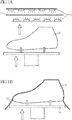
- heat may be provided by means of heating lamps 12 which radiate a substantial amount of infrared radiation onto the sheet 11, such that the temperature of the sheet 11 raises.
- the sheet of material 11 could be placed in a heating chamber or heat could be provided by heat conduction e.g. from a heating wire or similar heating device.
- the sides of a heating chamber are ceramic and heated.
- both sides of the material sheet 11 are heated, only a single side could be heated in other embodiments.
- the heat may be adjusted to selectively affect properties of the material to adjust a portion of the upper.
- the heat may be adjusted to make the material more pliable to achieve a stable, yet permanent deformation after the stretching step.
- materials are heated to 120°-160° C for about 60 seconds, but generally, materials may be heated to higher temperatures for different time periods.
- a non-woven sheet of material with a polyurethane coating may be heated to 200° C for 40 seconds. It is important to heat up the material to a so called "gel value" which allows a deformation in subsequent steps and a subsequent maintaining of the final, desired shape of the component after cooling.
- the heated sheet of material 11 is stretched by moving a last 13 into the sheet of material 11 as illustrated in Fig. 1B by the arrow.
- the last 13 defines the shape of the final component.
- the last 13 has the shape of a foot. Accordingly, the resulting component will be an entire shoe upper.
- the shape of the last 13 may generally vary.
- the sheet 11 stretches when last is moved into the sheet 11.
- the sheet 11 already conforms to some extent to the shape of the last 13.
- the sheet of material 11 may stretch by 30 %.
- the stretch may vary across the sheet 11. For example, the areas of the sheet 11 which first contact the last may be stretched more than other areas.
- a pressure lower than ambient pressure is applied between the stretched sheet of material and the last to conform the sheet of material to the last.
- the last 13 is secured on a vacuum plate 14.
- the vacuum plate 14 comprises holes (not shown in the illustration of Figures 1A and 1B ) which are connected to a vacuum source (not shown in the illustration of Figures 1A and 1B ).
- a lower pressure compared to ambient pressure is generated between the last 13 and the sheet 11 conforming the sheet 11 to the last 13.
- the last 13 comprises holes which are connected to a vacuum source. In this case, the last 13 need not be secured to a vacuum plate.
- the material After the material is heated and formed by the vacuum, it is cooled down to a temperature between -10° and 5° C. However, different temperatures may generally be used. This cooling step fixates the formed component.
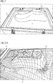
- Fig. 2 shows an example of a sheet of material 11 conformed to a last 13 by a vacuum according to the method of the invention.
- the sheet 11 may be held in a frame 21.
- the frame 21 helps to hold the sheet 11 static without tension before the sheet 11 is stretched. It also absorbs the tension forces which result in the sheet 11 when the sheet 11 is stretched.
- Figures 3A and 3B show another example of a sheet 11 conformed to a last 13 by a vacuum.
- Figures 3A and 3B primarily show the distribution of stretch in the sheet of material 11.
- the last 13 is positioned along a longitudinal axis of the vacuum plate and the frame 21.
- the last 13 is positioned diagonally relative to the vacuum plate and the frame 21.
- the position of the last in the frame might influence the material consumption and the size of the frame.
- An oval placed last may give more material allowance in the heel, where based on the last shape more stretch is required.
- the stretch achieved in the embodiment of figures 3A and 3B for a PU coated synthetic is as follows:
- the heel area and the top of the last 13 serve as a reference for calculating stretch.
- the heel area is the most critical area, where 30% stretch is achieved. In the toe area of the shoe, stretch achieved is less than 10%. In the middle portions of the shoe, the stretch achieved is around 20%. If an adequate stretch is not achieved in the heel area, in this case 30%, wrinkles form in the material.
- FIG. 4A illustrates the general principle in a top view.
- a loop of a heated cable is placed below the last 13 and the cable is pulled as illustrated by the arrows. In this way, the loop decreases in size and finally contacts the excess material which melts due to the heat and separates from the component as illustrated in Fig. 4B .
- the excess material may be removed by an oscillating knife or a laser that cuts the excess material from underneath the last 13.
- the resulting upper component can be secured to an insole board (not shown in the Figures).
- the insole board may already be in place below the last 13 at the beginning of the manufacturing process.
- a certain kind of adhesive is applied, either manually, per robot or pre-applied.
- a cold cement e.g. a hotmelt
- a hotmelt may be pre-applied such that when the material is wrapped underneath the last, the material is bonded to the insole board.
- the material may already begin to wrap around the bottom of the last 13 as can be seen in Figures 2, 3A and 3B .
- This wrapping effect may not be enough to fully attach the material to the cement on the insole board.
- the attaching of the upper material to the insole board can either be done with different methods from a traditional board lasting method to a process where a heated cable is used to pull the material under the last and secure it to the cold cement on the insole board.
- This heated cable may be the same cable that cuts the excess material as described above.
- the vacuum plate 14 may have a pressure potential of e.g. 10 bar and can be used to bond the upper material to the insole board.
- the upper material may be pressed against the insole board by a punch or similar.
- Fig. 5 illustrates a further optional step of the method according to the invention which is applicable when manufacturing an upper 51 or a part thereof.
- the last 13 which is still inside the upper 51 is removed.
- the step-in or throat opening of the upper is cut open and the corresponding material 52 is removed to finalize the manufacture of the upper 51 and to allow last removal.
- the last 13 is then deconstructed in order to allow its removal from the upper.
- a last 13 which is suitable for the method according to the invention is shown in Fig. 6 .
- the last 13 is made from two parts, namely a front part 61 and a back part 62 which are connected by a joint to allow rotating both parts relative to each other.
- the last 13 may be folded while still inside the upper 51 to allow for an easy removal through the throat opening of the upper 51.
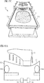
- FIGs 7A, 7B an 7C show an apparatus 70 which can be used in the context of the present invention.
- the apparatus comprises a frame 21 which is slideable along guide rails 71a and 71b.
- the frame 21 comprises an oval cutout 72 in which a sheet of material 11 can be fixed as shown in Fig. 7C .
- the inventors have found out that this oval shape optimizes material usage and material stretch.
- the sheet of material 11 can be placed over a last 13 to perform the method steps as described above in detail, i.e. heat the sheet of material 11, stretch the heated sheet of material 11 by moving the last 13 into the sheet of material 11, and apply a pressure lower than ambient pressure between the stretched sheet of material 11 and the last 13 to conform the sheet of material 11 to the last 13.
- Figures 8A , 8B and 8C show an exemplary embodiment according to the alternative of the present invention in which a pressure higher than ambient pressure is applied over a stretched sheet of material 11 to conform the sheet of material to a last 13.
- a last 13 is moved into a sheet of material 13 which is fixed in an opening of a chamber 81.
- the chamber 81 can be pressurized by pressure higher than ambient pressure, so that pressure higher than ambient pressure is applied over the sheet of material 13.
- the chamber 81 comprises a first valve 82.
- pressurized steam between 150° and 200°, for example at 185° C with a pressure of between 4 to 6 bar, for example at 5 bar is passed into the chamber 81 via the first valve 82.
- the steam is provided by a steam raising unit, but other means could be used as well.
- the chamber also comprises a second valve 83 which can be used to apply additional heat.
- additional heat may be provided by a conventional hot air blower to raise the heat about 200° C.
- additional heat of between 200° - 300° C is applied via the valve 83.
- the chamber 81 also comprises two bladders 84a and 84b, which can be inflated to apply additional pressure to the sheet of material 13.
- these bladders are shown in a deflated state, while in figures 8B and 8C , the bladders are shown in an inflated state.
- the edges of the sheet of material can additionally be folded to conform the sheet of material 11 to the last at the peripheral edges.
- rods 85a and 85b push the excess material over the bottom of the last 13 to close the material over the last.
- a gripper or robot arm 86 may be used to handle the last 13.
Landscapes
- Engineering & Computer Science (AREA)
- Mechanical Engineering (AREA)
- Chemical & Material Sciences (AREA)
- Materials Engineering (AREA)
- Footwear And Its Accessory, Manufacturing Method And Apparatuses (AREA)
Abstract
Description
- The present invention relates to a method of manufacturing a fully formed upper.
- A shoe is usually made from several components to provide the shoe with a three-dimensional shape. For example, the shoe upper can be made from several distinct parts which are joined e.g. by gluing, stitching or welding. While each of these parts basically comprises a flat, two-dimensional shape, suitably joining the components yields an upper with a three-dimensional shape.
- It is also known to form footwear components in a three-dimensional mold. For example,
US 7,178,267 B2 discloses footwear and footwear structures as well as methods for forming composite components for footwear or footwear structures. In forming the structures, two material layers are overlaid such that the two material layers are in contact with one another. - According to
DE 102 17 661 A1 a method of manufacturing an insole or sole from thermoplastic sheet material is described in which a blank is pre-heated to plasticizing temperature and placed on a last of a molding apparatus. A forming mat clamped in a frame is drawn down over the last and pulls the mat tangentially around the upper side of the last until the frame sits on a table. A chamber between the table, last and mat is evacuated to form the mat closely against the last. - According to
US 9,259,877 -
US 3,720,971 relates to vacuum and pressure forming techniques for conforming initially flat material to a molding surface. The molding surfaces may be of a shape whereby the preformed upper is convertible to the shape of the last merely by a bending operation. The mold shape can be arrived at by forming a sheet of resiliently bendable material such as unplasticized PVC to the last shape required to form a shell and, after removing the shell from the last, partially flattening it by spreading outwardly the opposite sides. - Further prior art is disclosed in
US 2002/ 0 012 784 A1 ,DE 71 34 386 U ,DE 19 47 025 U ,DE 20 53 601 A ,DE 20 30 088 A ,DE 20 56 910 A . - However, the methods known in the prior art partially have the disadvantage that only relatively small parts for shoes can be formed or cannot be formed to their final shape. For example, according to some methods it is not possible to fully form an entire upper for a shoe because the pressures used are too low. Furthermore, especially when mats or membranes are used, the material layers or sheets tend to form wrinkles when drawn by the vacuum which is not only an aesthetical problem, but may cause cracks in the final component due to an uneven distribution of material. Also, mats or membranes cause additional manufacturing steps as well as additional machine parts which need to be serviced.
- It is therefore, the underlying problem of the present invention to provide a method of manufacturing a component for a shoe, in particular a fully formed shoe upper, which at least partly overcomes the above-mentioned deficiencies.
- This problem is at least partly solved by a method of manufacturing a component for a shoe comprising the steps: (a.) providing a sheet of material; (b.) heating the sheet of material; (c.) stretching the heated sheet of material by moving a last into the sheet of material, wherein the last defines the shape of the component; and (d.) applying a pressure lower than ambient pressure between the stretched sheet of material and the last to conform the sheet of material to the last; or (e.) applying a pressure higher than ambient pressure over the stretched sheet of material to conform the sheet of material to the last.
- According to the method of the present invention, a sheet of material is first heated and then stretched by moving a last defining the shape of the component into the sheet of material. In this way, the sheet of material is stretched and preliminarily conformed to the shape of the last, before a vacuum is applied to finally conform the sheet of material to the last.
- The advantage of the present invention is a reduction of processing steps and machine components for manufacturing a component for a shoe. Rather than using a sequence of single steps, like cutting, forming, stitching, etc., the component can be formed around a last in a single processing step. By stretching the material over the last, the material can be completely formed around the last to make a large component, e.g. a fully-formed upper.
- Furthermore, the inventors have realized, that in particular the step of stretching the heated sheet of material decreases the formation of wrinkles in the subsequent step of conforming the sheet of material to the last by the vacuum. This is also due to the fact that a mat or membrane is not needed.
- Two alternative steps are provided according to the invention in order to conform the sheet of material to the last. According to the first alternative, a pressure lower than ambient pressure is applied between the stretched sheet of material and the last (method step d.). According to the second alternative, a pressure higher than ambient pressure is applied over the stretched sheet of material (method step e.). It should be noted that these alternatives can be performed exclusively, i.e. either step d. is performed or step e. is performed. Alternatively, both method steps may be performed, i.e. method step d. is performed and method step e. is performed. In the latter case, both alternatives may be performed simultaneously, i.e. at the same time, or subsequently, i.e. either step d. first, then step e., or step e. first, then step d.
- The component may be fully formed shoe upper. "Fully formed" in this context means that the upper comprises its final three-dimensional shape. The usual steps of shaping a two-dimensional upper into a three-dimensional shape, e.g. by gluing, welding or sewing can be omitted.
- The step of providing the sheet of material may comprise fixing the sheet of material in a frame. Thus, the sheet of material may be firmly held in place when the last is moved into the sheet.
- The sheet of material may be fixed in the frame essentially without tension. Thus, any stretching of the sheet is due to the last which is moved into the sheet. In this way, the sheet may optimally conform to the shape of the last. Alternatively, the material may be fastened by lose fixation or with slight tension.
- The step of stretching the heated sheet of material may comprise decreasing the distance between the frame and the last. Thus, in the context of the present invention, moving the last into the sheet may comprise moving the last towards the sheet, moving the sheet towards the last, or a combination of both movements.
- The last may be secured to a vacuum plate. Thus, the vacuum plate may create a vacuum between the sheet of material and the last, so that the sheet is optimally conformed to the shape of the last.
- Alternatively, or additionally, the last may be adapted to create a vacuum between the sheet of material and the last. For example, the last may comprise a porous material and/or may comprise a plurality of holes to allow the evacuation of air between the last and the sheet of material. To this end, the last may be connected to a vacuum source or pump.
- The method may be performed in a heating chamber. In this way, heat may be uniformly applied to the sheet of material which may further reduce the formation of wrinkles. Alternatively, the material may be heated, e.g. in a heating chamber or on a heater and then moved to a vacuum former where it is stretched and where pressure is applied.
- The step of stretching the heated sheet of material may comprise stretching at least of portion of the sheet of material by about 30%. The inventors have realized, that this amount of stretching allows to form the component around the last without failure and allows the component, in particular a fully formed shoe upper, to hold its new shape. Furthermore, at this amount of stretch the material can be brought under the last without cracks.
- The portion of the sheet of material to be stretched by about 30% may be located in peripheral areas of a shoe upper. For example, the heel portion of a shoe upper may be stretched by about 30%.
- In general, the stretching of the heated sheet of material may vary depending on location and/or material used.
- The step of stretching the heated sheet of material comprises controlling the stretch during stretching. In this way, the sheet can be provided with the optimal stretch before it is conformed to the last by the vacuum. Thus, uneven stretching the sheet can be avoided.
- The method may further comprise the step of cooling down the component. Thus, the component may be permanently conformed to the three-dimensional shape of the component.
- The component may be a portion of an upper for a shoe. In particular, the component may essentially be the entire upper of a shoe. "Essentially" in this context means except for additional components like reinforcements (e.g. heel counter and toe cap), laces, logos, etc. However, it is also possible with the method according to the invention to avoid any added components like collar binding or tongue. Thus, a three-dimensional upper can be formed by the method of the present invention in one process step in an automated process. The advantageous combination of method steps avoids or at least reduces the formation of wrinkles.
- The method may further comprise the step of placing an insole board below the last. Thus, the insole board may directly be integrated with the component. An additional step of joining the insole board to the component may be omitted which saves process time and costs. For example, the component may essentially be an entire upper as described above and the insole board may directly be integrated into the upper while forming the upper in its three-dimensional shape.
- The insole board may be placed below the last before the step of stretching the heated sheet of material. Thus, when conforming the sheet to the last, the insole board is arranged inside the resulting upper, i.e. in its correct position.
- The method may further comprise the step of bonding the insole board to the portion of the upper. Thus, the insole board may be permanently fixed to the portion of the upper while forming the portion of the upper. An additional, separate step of attaching the insole board can be omitted saving manufacturing time and costs.
- The method may further comprise the steps of applying an adhesive to the insole board and bonding the insole board to the portion of the upper by means of the adhesive. Adhesives are easy to handle and allow for a firm and durable connection between the insole board and the portion of the upper.
- The method may further comprise the step of clamping the insole board and the portion of the upper between the last and the vacuum plate. This allows to exert pressure to the insole board and the portion of the upper in order to join both parts. This is especially advantageous when using an adhesive which often requires the application of pressure to achieve a firm bond. The pressure can be generated by the vacuum, such that no additional pressure source is needed.
- The method may further comprise the step of removing excess material from the component by using a heated cable, an oscillating knife or a laser. Thus, any remaining material which shall not be part of the final component is removed. This is preferably done while the component is still on the last, so that the component is fixed with respect to the cable, knife or laser.
- The method may further comprise the step of forming at least one aperture in the component to remove the last. Advantageously, this aperture forms an opening of the final component. For example, when forming a portion of an upper or essentially an entire upper, the aperture can be the throat opening.
- The method may further comprise the step of deconstructing the last to fit through the aperture. In this way, the aperture may be smaller than the fully deployed last.
- The step of applying a pressure higher than ambient pressure over the stretched sheet of material may be performed without a mat or membrane applied over the stretched sheet of material. In this way, additional machine components and method steps may be omitted.
- Pressure higher than ambient pressure may be applied over the stretched sheet of material by gas or steam. Thus, the pressure may be uniformly applied over the sheet of material which helps to uniformly conform the sheet to the last.
- The gas or steam may come into contact with the stretched sheet of material. Thus, an additional mat or membrane may be avoided as the gas or steam may directly exert pressure and heat onto the sheet.
- The method may further comprise the step of heating the gas or steam. In this way, the sheet of material gets softer and may better conform to the last.
- The step of applying a pressure higher than ambient pressure over the stretched sheet of material may include inflating at least one bladder such that it comes into contact with at least a portion of the stretched sheet of material. In this way, the sheet may additionally or alternatively be conformed to the last.
- Another aspect of the present invention relates to a component for a shoe being manufactured according to the method as described herein. The component may be a portion of an upper for a shoe.
- Currently preferred examples and embodiments of the present invention will be described in the following, with reference to the following figures:
- Figs. 1A, 1B:
- an illustration of an embodiment of the method according to the invention;
- Fig. 2:
- an example of a sheet of material conformed to a last by a vacuum according to the method of the invention;
- Figs. 3A, 3B:
- another example of a sheet conformed to a last by a vacuum according to the method of the invention and the different amounts of stretch in the sheet;
- Figs. 4A, 4B:
- an exemplary illustration of removing excess material from a component;
- Fig. 5:
- a further optional step of the method according to the invention;
- Fig. 6:
- an exemplary last which is suitable for the method according to the invention;
- Figs 7A-C:
- an apparatus which can be used in the context of the present invention; and
- Figs. 8A-C:
- an exemplary illustration of an embodiment according to the second alternative of the present invention.
- An exemplary embodiment of a method according to the invention will now be described with respect to the illustrations of
Figures 1A and 1B . Generally, the method according to the invention is suitable to manufacture entire shoe uppers as well as parts thereof, such as toe caps, heel counters, vamp portions, reinforcements, etc. The method may also be used to manufacture sole structures, such as outsoles, midsoles and insoles as well as parts thereof. - According to the inventive method, a sheet of material is provided in a first step. In
Figures 1A and 1B such a sheet is denoted with thereference numeral 11. A sheet in this context is understood as an object having a thickness which is smaller than its length and width. Usually, the thickness of a sheet is substantially smaller than its length and width. It should be noted that in the context of the present invention, thesheet 11 may have an arbitrary shape, i.e. rectangular, quadratic, circular, elliptical, etc. - The
sheet 11 is made from material which is suitable to be formed when heated. Exemplary materials include polyurethane synthetic, polyester and thermoplastic polyurethane (TPU). Thesheet 11 is preferably a PU synthetic or a textile material, i.e. is made from fibers, such as a woven, non-woven, weft knit, warp knit, etc. However, it is also possible to use non-textile materials such as a plastic sheet, film, etc. Thesheet 11 may also comprise a coating of a material which may be formed when heated. - The following table presents different options of materials to use for the
sheet 11. The table shows the material type in the column 2, a short material description in the column 3, the stretch under a load of 100 N in column 4, the optimal molding time in column 5, the optimal heating time in column 6 and the working temperature in the last column.Material Group Material Type Material description Stretch under load 100 N Molding time in sec Heating time in sec Working temp in ° C # 1 PU coated synthetic with stretch function non-woven, or non-woven microfiber, with or without a TPU film in between the layers Stretchable (by hand) made out of non-stretch polyester or nylon or mixture between both fibers, needled felt, made stretchy by manufacturi ng process of non-woven. 10-30% 60 sec. 60 - 80 sec. 140-180°C With a PU resin of 0,1 to 1,0mm. Stretchable in 12 or 3 directions #2 PU synthetic non-woven or non-woven microfiber without stretch function with or without a TPU film in between the two layers Non stretchable (by hand) non-woven backed PU resins. 0,1 to 1,0mm pu thickness 10-20% 60 sec. 60 - 80 sec. 140-180°C #3 TPU films laminated or coated to textile stretch or non-stretch, stretch in 1, 2 or 3 ways TPU films with the thickness of 0,1mm to 2mm laminated with circular or weft knitted distance meshes (thickness of 20-40% 40 sec. 60 - 80 sec. 120 - 170°C 1mm to 2mm) with an overall thickness of 2-7 mm. No matter which way of lamination or if the TPU is coated #4 PU coated knitwear Stretch knit polyester or nylon or mixture with a spandex content coated with a PU resin called stretch PU synthetic, with PU, PU Hotmelt, or TPU as top layer. The description is also valid for knitwear backed PU resins without being able to be stretched by hand 30-60% 40 - 60 sec. 60 - 80 sec. 120 - 160°C #5 Stretch textile without spandex Circular knit without spandex but with stretch in 1, 2 or 3 ways, with or without a coating or laminated addition 20-40% 60 - 80 sec. 60 - 80 sec. 150-190°C #6 Stretch textile with spandex Warp or circular knit or woven with spandex content and stretch in 1, 2 or 3 ways 40-70% 60 - 80 sec. 60 - 80 sec. 150-180° C # 7 Textile Warp knit without spandex content without stretch, as well as woven or weft knit 30-50% 60 - 80 sec. 80 - 120 sec. 170 - 220°C #8 Textile with TPU yarns Circular jaquard knit with TPU yarns with a melting point above 80 °C, 20-90% 40 - 60 sec. 60 - 100 sec. 150-200°C or warp knit or any other type of knit, stretchable by hand #9 Textile with adhesive TPU yarns Circular jaquard knit or flat knit polyester - adhesive yarn with PES or PA combination for creating the stand. With a melting point of 80 °C and above 40-90% 40 - 60 sec. 60 - 100 sec. 120 - 180°C #10 Textile with low melting point polyester yarns Flat knit with special copolyester yarns with a low melting point of 80° plus 20-50% 40 - 60 sec. 60 - 80 sec. 130-190° C # 11 TPU film without any backing 70-100% 30-40 sec. 40 - 60 sec. 100 - 120°C - It is preferable that the sheet of
material 11 is held static in a frame or similar construction (not shown in the illustration ofFigures 1A and 1B ). Furthermore, thesheet 11 is preferably held without tension, but may be fastened by lose fixation or with slight tension. - In a next step of the inventive method, the sheet of
material 11 is heated. As illustrated inFig. 1A , heat may be provided by means ofheating lamps 12 which radiate a substantial amount of infrared radiation onto thesheet 11, such that the temperature of thesheet 11 raises. However, other means of heating could be used as well. For example, the sheet ofmaterial 11 could be placed in a heating chamber or heat could be provided by heat conduction e.g. from a heating wire or similar heating device. In an embodiment, the sides of a heating chamber are ceramic and heated. Furthermore, while inFig. 1A both sides of thematerial sheet 11 are heated, only a single side could be heated in other embodiments. - The heat may be adjusted to selectively affect properties of the material to adjust a portion of the upper. For example, the heat may be adjusted to make the material more pliable to achieve a stable, yet permanent deformation after the stretching step.
- Typically, materials are heated to 120°-160° C for about 60 seconds, but generally, materials may be heated to higher temperatures for different time periods. For example, a non-woven sheet of material with a polyurethane coating may be heated to 200° C for 40 seconds. It is important to heat up the material to a so called "gel value" which allows a deformation in subsequent steps and a subsequent maintaining of the final, desired shape of the component after cooling.
- In a next step of the inventive method, the heated sheet of
material 11 is stretched by moving a last 13 into the sheet ofmaterial 11 as illustrated inFig. 1B by the arrow. Generally, the last 13 defines the shape of the final component. Thus, in the example ofFigure 1A and 1B the last 13 has the shape of a foot. Accordingly, the resulting component will be an entire shoe upper. However, as explained above, a variety of different components for a shoe may be manufactured with the inventive method. Therefore, the shape of the last 13 may generally vary. - As illustrated in
Fig. 1B , thesheet 11 stretches when last is moved into thesheet 11. Thus, thesheet 11 already conforms to some extent to the shape of the last 13. The sheet ofmaterial 11 may stretch by 30 %. Generally, the stretch may vary across thesheet 11. For example, the areas of thesheet 11 which first contact the last may be stretched more than other areas. - In the next step, a pressure lower than ambient pressure is applied between the stretched sheet of material and the last to conform the sheet of material to the last. In the example of
Figures 1A and 1B the last 13 is secured on avacuum plate 14. Thevacuum plate 14 comprises holes (not shown in the illustration ofFigures 1A and 1B ) which are connected to a vacuum source (not shown in the illustration ofFigures 1A and 1B ). Thus, a lower pressure compared to ambient pressure is generated between the last 13 and thesheet 11 conforming thesheet 11 to the last 13. - It is also possible that the last 13 comprises holes which are connected to a vacuum source. In this case, the last 13 need not be secured to a vacuum plate.
- After the material is heated and formed by the vacuum, it is cooled down to a temperature between -10° and 5° C. However, different temperatures may generally be used. This cooling step fixates the formed component.
-
Fig. 2 shows an example of a sheet ofmaterial 11 conformed to a last 13 by a vacuum according to the method of the invention. As can be seen in this example, thesheet 11 may be held in aframe 21. Theframe 21 helps to hold thesheet 11 static without tension before thesheet 11 is stretched. It also absorbs the tension forces which result in thesheet 11 when thesheet 11 is stretched. -
Figures 3A and3B show another example of asheet 11 conformed to a last 13 by a vacuum.Figures 3A and3B primarily show the distribution of stretch in the sheet ofmaterial 11. InFig. 3A the last 13 is positioned along a longitudinal axis of the vacuum plate and theframe 21. InFig. 3B the last 13 is positioned diagonally relative to the vacuum plate and theframe 21. Generally, the position of the last in the frame might influence the material consumption and the size of the frame. An oval placed last may give more material allowance in the heel, where based on the last shape more stretch is required. - The stretch achieved in the embodiment of
figures 3A and3B for a PU coated synthetic is as follows: The heel area and the top of the last 13 serve as a reference for calculating stretch. The heel area is the most critical area, where 30% stretch is achieved. In the toe area of the shoe, stretch achieved is less than 10%. In the middle portions of the shoe, the stretch achieved is around 20%. If an adequate stretch is not achieved in the heel area, in this case 30%, wrinkles form in the material. - After forming the component on the last, excess material may be removed as illustrated in
Figures 4A and4B .Fig. 4A illustrates the general principle in a top view. A loop of a heated cable is placed below the last 13 and the cable is pulled as illustrated by the arrows. In this way, the loop decreases in size and finally contacts the excess material which melts due to the heat and separates from the component as illustrated inFig. 4B . - Alternatively, the excess material may be removed by an oscillating knife or a laser that cuts the excess material from underneath the last 13.
- In one embodiment of the present invention, after the
sheet 11 is conformed to the shape of the last 13, the resulting upper component can be secured to an insole board (not shown in the Figures). The insole board may already be in place below the last 13 at the beginning of the manufacturing process. On the insole board a certain kind of adhesive is applied, either manually, per robot or pre-applied. For example, a cold cement (e.g. a hotmelt) may be pre-applied such that when the material is wrapped underneath the last, the material is bonded to the insole board. - Depending on the material used for the
sheet 11, the material may already begin to wrap around the bottom of the last 13 as can be seen inFigures 2, 3A and3B . This wrapping effect, however, may not be enough to fully attach the material to the cement on the insole board. The attaching of the upper material to the insole board can either be done with different methods from a traditional board lasting method to a process where a heated cable is used to pull the material under the last and secure it to the cold cement on the insole board. This heated cable may be the same cable that cuts the excess material as described above. Thevacuum plate 14 may have a pressure potential of e.g. 10 bar and can be used to bond the upper material to the insole board. Alternatively or additionally, the upper material may be pressed against the insole board by a punch or similar. -
Fig. 5 illustrates a further optional step of the method according to the invention which is applicable when manufacturing an upper 51 or a part thereof. In this step, the last 13 which is still inside the upper 51 is removed. Thus, the step-in or throat opening of the upper is cut open and the correspondingmaterial 52 is removed to finalize the manufacture of the upper 51 and to allow last removal. The last 13 is then deconstructed in order to allow its removal from the upper. - An exemplary last 13 which is suitable for the method according to the invention is shown in
Fig. 6 . As can be seen, the last 13 is made from two parts, namely afront part 61 and aback part 62 which are connected by a joint to allow rotating both parts relative to each other. Thus, the last 13 may be folded while still inside the upper 51 to allow for an easy removal through the throat opening of the upper 51. -
Figures 7A, 7B an 7C show anapparatus 70 which can be used in the context of the present invention. As can best be seen inFig. 7B , the apparatus comprises aframe 21 which is slideable alongguide rails frame 21 comprises an oval cutout 72 in which a sheet ofmaterial 11 can be fixed as shown inFig. 7C . The inventors have found out that this oval shape optimizes material usage and material stretch. - By means of the
frame 21, the sheet ofmaterial 11 can be placed over a last 13 to perform the method steps as described above in detail, i.e. heat the sheet ofmaterial 11, stretch the heated sheet ofmaterial 11 by moving the last 13 into the sheet ofmaterial 11, and apply a pressure lower than ambient pressure between the stretched sheet ofmaterial 11 and the last 13 to conform the sheet ofmaterial 11 to the last 13. -
Figures 8A ,8B and 8C show an exemplary embodiment according to the alternative of the present invention in which a pressure higher than ambient pressure is applied over a stretched sheet ofmaterial 11 to conform the sheet of material to a last 13. - As shown in
Fig. 8A , a last 13 is moved into a sheet ofmaterial 13 which is fixed in an opening of achamber 81. Thechamber 81 can be pressurized by pressure higher than ambient pressure, so that pressure higher than ambient pressure is applied over the sheet ofmaterial 13. To this end, thechamber 81 comprises afirst valve 82. In an exemplary embodiment, pressurized steam between 150° and 200°, for example at 185° C with a pressure of between 4 to 6 bar, for example at 5 bar is passed into thechamber 81 via thefirst valve 82. The steam is provided by a steam raising unit, but other means could be used as well. - The chamber also comprises a
second valve 83 which can be used to apply additional heat. For example, additional heat may be provided by a conventional hot air blower to raise the heat about 200° C. In an exemplary embodiment additional heat of between 200° - 300° C is applied via thevalve 83. - In the exemplary embodiment of
figures 8A ,8B and 8C , thechamber 81 also comprises twobladders material 13. InFig. 8A , these bladders are shown in a deflated state, while infigures 8B and 8C , the bladders are shown in an inflated state. - As shown in
Fig. 8C by means of the arrows, the edges of the sheet of material can additionally be folded to conform the sheet ofmaterial 11 to the last at the peripheral edges. To this end,rods robot arm 86 may be used to handle the last 13. - In the following, further embodiments are described to facilitate the understanding of the invention:
- 1. Method of manufacturing a component for a shoe comprising the steps:
- a. providing a sheet of material (11);
- b. heating the sheet of material (11);
- c. stretching the heated sheet of material (11) by moving a last (13) into the sheet of material (11), wherein the last (13) defines the shape of the component; and
- d. applying a pressure lower than ambient pressure between the stretched sheet of material (11) and the last (13) to conform the sheet of material (11) to the last (13); or
- e. applying a pressure higher than ambient pressure over the stretched sheet of material (11) to conform the sheet of material (11) to the last (13).
- 2. Method according to the preceding embodiment, wherein the component is a fully formed shoe upper.
- 3. Method according to one of the preceding embodiments, wherein the step of providing the sheet of material (11) comprises fixing the sheet of material (11) in a frame (21).
- 4. Method according to the preceding embodiment, wherein the sheet of material (11) is fixed in the frame (21) essentially without tension.
- 5. Method according to one of embodiments 3 to 0, wherein the step of stretching the heated sheet of material (11) comprises decreasing the distance between the frame (21) and the last (13).
- 6. Method according to one of the preceding embodiments, wherein the last (13) is secured to a vacuum plate (14).
- 7. Method according to one of the preceding embodiments, wherein the method is performed in a heating chamber.
- 8. Method according to one of the preceding embodiments, wherein the step of stretching the heated sheet of material (11) comprises stretching at least of portion of the sheet of material (11) by about 30%.
- 9. Method according to one of the preceding embodiments, wherein the step of stretching the heated sheet of material (11) comprises controlling the stretch during stretching.
- 10. Method according to one of the preceding embodiments, further comprising the step of cooling down the component.
- 11. Method according to one of the preceding embodiments, wherein the component is a portion of an upper for a shoe.
- 12. Method according to the preceding embodiment, further comprising the step of placing an insole board below the last (13).
- 13. Method according to the preceding embodiment, wherein the insole board is placed below the last before the step of stretching the heated sheet of material (11).
- 14. Method according to one of embodiments 0 to 0, further comprising the step of bonding the insole board to the portion of the upper.
- 15. Method according to the preceding embodiment, further comprising the steps of applying an adhesive to the insole board and bonding the insole board to the portion of the upper by means of the adhesive.
- 16. Method according to embodiment 0 and one of embodiments 0 to 15, further comprising the step of clamping the insole board and the portion of the upper between the last and the vacuum plate (14).
- 17. Method according to one of the preceding embodiments, further comprising the step of removing excess material from the component by using a heated cable, an oscillating knife or a laser.
- 18. Method according to one of the preceding embodiments, further comprising the step of forming at least one aperture in the component to remove the last.
- 19. Method according to the preceding embodiment, further comprising the step of deconstructing the last (13) to fit through the aperture.
- 20. Method according to one of the preceding embodiments, wherein the step of applying a pressure higher than ambient pressure over the stretched sheet of material (11) is performed without a mat or membrane applied over the stretched sheet of material (11).
- 21. Method according to one of the preceding embodiments, wherein pressure higher than ambient pressure is applied over the stretched sheet of material (11) by a gas.
- 22. Method according to the preceding embodiment, wherein the gas comes into contact with the stretched sheet of material (11).
- 23. Method according to one of
embodiments 21 or 22, further comprising the step of heating the gas. - 24. Method according to one of the preceding embodiments, wherein the step of applying a pressure higher than ambient pressure over the stretched sheet of material (11) includes inflating at least one bladder (84a, 84b) such that it comes into contact with at least a portion of the stretched sheet of material (11).
- 25. Component for a shoe being manufactured according to one of the preceding embodiments.
- 26. Component for a shoe according to the preceding embodiment, wherein the component is a portion of an upper for a shoe.
- 27. Component for a shoe according to embodiment 25, wherein the component is a fully formed shoe upper.
Claims (15)
- Method of manufacturing a component for a shoe comprising the steps:a. providing a sheet of material (11);b. heating the sheet of material (11);c. stretching the heated sheet of material (11) by moving a last (13) into the sheet of material (11), wherein the last (13) defines the shape of the component; andd. applying a pressure lower than ambient pressure between the stretched sheet of material (11) and the last (13) to conform the sheet of material (11) to the last (13); ore. applying a pressure higher than ambient pressure over the stretched sheet of material (11) to conform the sheet of material (11) to the last (13).
- Method according to the preceding claim, wherein the component is a fully formed shoe upper.
- Method according to one of the preceding claims, wherein the step of providing the sheet of material (11) comprises fixing the sheet of material (11) in a frame (21).
- Method according to the preceding claim, wherein the sheet of material (11) is fixed in the frame (21) essentially without tension.
- Method according to one of claims 3 to 4, wherein the step of stretching the heated sheet of material (11) comprises decreasing the distance between the frame (21) and the last (13).
- Method according to one of the preceding claims, wherein the component is a portion of an upper for a shoe.
- Method according to the preceding claim, further comprising the step of placing an insole board below the last (13).
- Method according to the preceding claim, wherein the insole board is placed below the last before the step of stretching the heated sheet of material (11).
- Method according to one of claims 7 to 8, further comprising the step of bonding the insole board to the portion of the upper.
- Method according to the preceding claim, further comprising the steps of applying an adhesive to the insole board and bonding the insole board to the portion of the upper by means of the adhesive.
- Method according to claim 6 and one of claims 9 to 15, further comprising the step of clamping the insole board and the portion of the upper between the last and the vacuum plate (14).
- Method according to the preceding claim, further comprising the step of deconstructing the last (13) to fit through the aperture.
- Method according to one of the preceding claims, wherein the step of applying a pressure higher than ambient pressure over the stretched sheet of material (11) is performed without a mat or membrane applied over the stretched sheet of material (11).
- Method according to one of the preceding claims, wherein the step of applying a pressure higher than ambient pressure over the stretched sheet of material (11) includes inflating at least one bladder (84a, 84b) such that it comes into contact with at least a portion of the stretched sheet of material (11).
- Component for a shoe being manufactured according to one of the preceding claims.
Applications Claiming Priority (1)
| Application Number | Priority Date | Filing Date | Title |
|---|---|---|---|
| DE102016224240.7A DE102016224240B4 (en) | 2016-12-06 | 2016-12-06 | Method of making a fully molded upper |
Publications (2)
| Publication Number | Publication Date |
|---|---|
| EP3332662A1 true EP3332662A1 (en) | 2018-06-13 |
| EP3332662B1 EP3332662B1 (en) | 2020-10-07 |
Family
ID=60661741
Family Applications (1)
| Application Number | Title | Priority Date | Filing Date |
|---|---|---|---|
| EP17204332.5A Active EP3332662B1 (en) | 2016-12-06 | 2017-11-29 | Method of manufacturing a fully formed upper |
Country Status (5)
| Country | Link |
|---|---|
| US (1) | US11284675B2 (en) |
| EP (1) | EP3332662B1 (en) |
| JP (1) | JP2018089380A (en) |
| CN (1) | CN108143051B (en) |
| DE (1) | DE102016224240B4 (en) |
Families Citing this family (10)
| Publication number | Priority date | Publication date | Assignee | Title |
|---|---|---|---|---|
| TWI674967B (en) * | 2018-04-02 | 2019-10-21 | 捷欣企業股份有限公司 | Manufacturing method of a shoe and the manufacturing system therefore |
| EP3622844A1 (en) * | 2018-09-14 | 2020-03-18 | Low & Bonar B.V. | Method for providing a footwear upper |
| CN109537177A (en) * | 2018-12-26 | 2019-03-29 | 陈雪源 | A kind of margin to seam method of socks and socks vamp |
| JP7026084B2 (en) * | 2019-08-06 | 2022-02-25 | 株式会社アシックス | How to make shoes |
| CN112335996A (en) | 2019-08-06 | 2021-02-09 | 株式会社爱世克私 | Shoe, shoe manufacturing method, and shoe upper manufacturing method |
| CN117958530A (en) * | 2019-09-23 | 2024-05-03 | 耐克创新有限合伙公司 | Manufacturing system for applying material to articles of apparel and method of using the same |
| CN112674432B (en) * | 2019-10-18 | 2025-11-21 | 株式会社爱世克私 | Shoe last, method for manufacturing shoe last, and method for manufacturing vamp |
| US11439206B2 (en) * | 2019-12-17 | 2022-09-13 | Under Armour, Inc. | Method of making an article of footwear with braided upper |
| IT202000001459A1 (en) * | 2020-01-24 | 2021-07-24 | Trere Innovation S R L | STRUCTURE AND PROCEDURE FOR MAKING A SHOE WITH A KNITTED UPPER. |
| CN112917963B (en) * | 2021-01-15 | 2023-02-14 | 黎明职业大学 | Machining device and technology for anti-skid sole |
Citations (7)
| Publication number | Priority date | Publication date | Assignee | Title |
|---|---|---|---|---|
| US3720971A (en) * | 1969-11-20 | 1973-03-20 | Shoe & Allied Trades Res Ass | Shoe making |
| US20140223671A1 (en) * | 2013-02-14 | 2014-08-14 | Nike, Inc. | Last With Retractable Pins |
| US20140237738A1 (en) * | 2013-02-22 | 2014-08-28 | Nike, Inc. | System And Method For Forming An Article |
| US20150305448A1 (en) * | 2014-04-28 | 2015-10-29 | Nike, Inc. | Method of Vacuum Forming A Footwear Upper |
| US20160031164A1 (en) * | 2013-03-13 | 2016-02-04 | Dsm Ip Assets B.V. | Systems and method for producing three-dimensional articles from flexible composite materials |
| WO2016107990A1 (en) * | 2014-12-31 | 2016-07-07 | Salomon S.A.S. | Method for manufacturing footwear, footwear produced using said method, and machine for manufacturing footwear |
| US20160206046A1 (en) * | 2015-01-16 | 2016-07-21 | Nike, Inc. | Vacuum Formed Knit Sole System for an Article of Footwear Incorporating a Knitted Component |
Family Cites Families (25)
| Publication number | Priority date | Publication date | Assignee | Title |
|---|---|---|---|---|
| DE7134386U (en) * | 1973-07-19 | Minke F | Device for producing molded parts for orthopedic purposes, such as impressions of lasts and other molded articles, elastic inserts and the like | |
| US2330260A (en) | 1942-01-24 | 1943-09-28 | United Shoe Machinery Corp | Method of making shoe lasts |
| US2540217A (en) * | 1946-05-03 | 1951-02-06 | United Shoe Machinery Corp | Shoemaking apparatus |
| US3064111A (en) * | 1960-06-27 | 1962-11-13 | Columbia Ribbon & Carbon | Plastic cutting device |
| DE1947025U (en) * | 1966-01-18 | 1966-09-29 | Albeko Schuhmasch | DEVICE FOR THE PRODUCTION OF BASIC MODELS FOR SHOE PARTS, E.G. UPPER, HEEL PARTS, INSOLES OD. DGL. |
| US3641603A (en) * | 1969-01-29 | 1972-02-15 | Shoe & Allied Trades Res Ass | Shoe making |
| US3525110A (en) * | 1969-03-07 | 1970-08-25 | Batchelder Rubico Inc | Method of making shoes over sheathed lasts |
| NL7008755A (en) * | 1969-06-17 | 1970-12-21 | ||
| DE1947025A1 (en) | 1969-09-17 | 1971-04-01 | Krempel August Soehne | Slimes for dispersing aids |
| DE1951212A1 (en) | 1969-10-10 | 1971-05-13 | Hoffmann Gmbh Gustav | Synthetic leather shoes |
| NL7015899A (en) * | 1969-10-21 | 1971-05-04 | ||
| NL7016796A (en) * | 1969-11-20 | 1971-05-24 | ||
| JPS4939616B1 (en) * | 1970-12-29 | 1974-10-26 | ||
| GB1454518A (en) * | 1973-02-15 | 1976-11-03 | British United Shoe Machinery | Manufacture of shoes |
| JPS54103153A (en) * | 1978-01-31 | 1979-08-14 | Takerou Ogawa | Method of glueing shoeelike body |
| DE3937106A1 (en) | 1989-11-07 | 1991-05-08 | Akzo Gmbh | SHOE LINING WITH A LAMINATE |
| JP3058398B2 (en) * | 1994-07-27 | 2000-07-04 | アキレス株式会社 | Method of manufacturing shoe cover |
| US6558784B1 (en) * | 1999-03-02 | 2003-05-06 | Adc Composites, Llc | Composite footwear upper and method of manufacturing a composite footwear upper |
| DE10217661B4 (en) | 2002-04-19 | 2006-04-27 | Hermann Springer Gmbh | Method and device for producing inserts |
| US7178267B2 (en) | 2003-12-12 | 2007-02-20 | Polyworks, Inc. | Method for forming footwear structures using thermoforming |
| US9259877B2 (en) | 2013-02-22 | 2016-02-16 | Nike, Inc. | System and method for applying heat and pressure to three-dimensional articles |
| FR3007317B1 (en) * | 2013-06-25 | 2015-10-23 | Salomon Sas | METHOD FOR MANUFACTURING A HOLLOW OBJECT |
| EP3104728B1 (en) * | 2014-02-14 | 2018-10-17 | W.L. Gore & Associates, Inc. | Conformable seamless shoe inserts and footwear assemblies and methods therefor |
| US20160166011A1 (en) * | 2014-12-10 | 2016-06-16 | Nike, Inc. | Portable Manufacturing System For Articles of Footwear |
| CN106037153A (en) * | 2016-06-16 | 2016-10-26 | 河南荣光鞋业有限公司 | Production process of safety shoes |
-
2016
- 2016-12-06 DE DE102016224240.7A patent/DE102016224240B4/en active Active
-
2017
- 2017-11-29 EP EP17204332.5A patent/EP3332662B1/en active Active
- 2017-12-05 JP JP2017233032A patent/JP2018089380A/en active Pending
- 2017-12-05 CN CN201711266706.2A patent/CN108143051B/en active Active
- 2017-12-06 US US15/833,378 patent/US11284675B2/en active Active
Patent Citations (7)
| Publication number | Priority date | Publication date | Assignee | Title |
|---|---|---|---|---|
| US3720971A (en) * | 1969-11-20 | 1973-03-20 | Shoe & Allied Trades Res Ass | Shoe making |
| US20140223671A1 (en) * | 2013-02-14 | 2014-08-14 | Nike, Inc. | Last With Retractable Pins |
| US20140237738A1 (en) * | 2013-02-22 | 2014-08-28 | Nike, Inc. | System And Method For Forming An Article |
| US20160031164A1 (en) * | 2013-03-13 | 2016-02-04 | Dsm Ip Assets B.V. | Systems and method for producing three-dimensional articles from flexible composite materials |
| US20150305448A1 (en) * | 2014-04-28 | 2015-10-29 | Nike, Inc. | Method of Vacuum Forming A Footwear Upper |
| WO2016107990A1 (en) * | 2014-12-31 | 2016-07-07 | Salomon S.A.S. | Method for manufacturing footwear, footwear produced using said method, and machine for manufacturing footwear |
| US20160206046A1 (en) * | 2015-01-16 | 2016-07-21 | Nike, Inc. | Vacuum Formed Knit Sole System for an Article of Footwear Incorporating a Knitted Component |
Also Published As
| Publication number | Publication date |
|---|---|
| JP2018089380A (en) | 2018-06-14 |
| CN108143051A (en) | 2018-06-12 |
| DE102016224240B4 (en) | 2022-02-03 |
| EP3332662B1 (en) | 2020-10-07 |
| US11284675B2 (en) | 2022-03-29 |
| CN108143051B (en) | 2021-11-12 |
| DE102016224240A1 (en) | 2018-06-07 |
| US20180153265A1 (en) | 2018-06-07 |
Similar Documents
| Publication | Publication Date | Title |
|---|---|---|
| EP3332662B1 (en) | Method of manufacturing a fully formed upper | |
| US11297901B2 (en) | Shoe with composite upper and method of making the same | |
| US10595591B2 (en) | Shoe with composite upper and foam element and method of making same | |
| EP3153052B1 (en) | Manufacturing method for coating a fabric with a three-dimensional shape | |
| US8566991B2 (en) | Method for manufacturing a waterproof and vapor-permeable shoe and shoe obtained with the method | |
| US20180000195A1 (en) | Thermoforming footwear method | |
| US7712173B2 (en) | Method of manufacturing an ice skate | |
| CN106455744A (en) | Components for articles of footwear comprising lightweight selectively supportive textile components | |
| US7451991B2 (en) | Ice skate boot | |
| CN108851358B (en) | Method for manufacturing upper template according to shoe tree last shape and upper surface forming process | |
| EP2087803B1 (en) | Method of making a skate boot | |
| CA2497026C (en) | Sporting boot | |
| CN116784569B (en) | Preparation process of shoe upper, shoe upper and shoe | |
| CA2496987C (en) | Ice skate boot | |
| EP1690459B1 (en) | Ice skate boot | |
| JPH0512921B2 (en) | ||
| HK1167581B (en) | Method for manufacturing a waterproof and vapor-permeable shoe and shoe obtained with the method |
Legal Events
| Date | Code | Title | Description |
|---|---|---|---|
| PUAI | Public reference made under article 153(3) epc to a published international application that has entered the european phase |
Free format text: ORIGINAL CODE: 0009012 |
|
| STAA | Information on the status of an ep patent application or granted ep patent |
Free format text: STATUS: REQUEST FOR EXAMINATION WAS MADE |
|
| 17P | Request for examination filed |
Effective date: 20171129 |
|
| AK | Designated contracting states |
Kind code of ref document: A1 Designated state(s): AL AT BE BG CH CY CZ DE DK EE ES FI FR GB GR HR HU IE IS IT LI LT LU LV MC MK MT NL NO PL PT RO RS SE SI SK SM TR |
|
| AX | Request for extension of the european patent |
Extension state: BA ME |
|
| STAA | Information on the status of an ep patent application or granted ep patent |
Free format text: STATUS: EXAMINATION IS IN PROGRESS |
|
| 17Q | First examination report despatched |
Effective date: 20190429 |
|
| GRAP | Despatch of communication of intention to grant a patent |
Free format text: ORIGINAL CODE: EPIDOSNIGR1 |
|
| STAA | Information on the status of an ep patent application or granted ep patent |
Free format text: STATUS: GRANT OF PATENT IS INTENDED |
|
| INTG | Intention to grant announced |
Effective date: 20200422 |
|
| GRAS | Grant fee paid |
Free format text: ORIGINAL CODE: EPIDOSNIGR3 |
|
| GRAA | (expected) grant |
Free format text: ORIGINAL CODE: 0009210 |
|
| STAA | Information on the status of an ep patent application or granted ep patent |
Free format text: STATUS: THE PATENT HAS BEEN GRANTED |
|
| AK | Designated contracting states |
Kind code of ref document: B1 Designated state(s): AL AT BE BG CH CY CZ DE DK EE ES FI FR GB GR HR HU IE IS IT LI LT LU LV MC MK MT NL NO PL PT RO RS SE SI SK SM TR |
|
| REG | Reference to a national code |
Ref country code: GB Ref legal event code: FG4D |
|
| REG | Reference to a national code |
Ref country code: CH Ref legal event code: EP Ref country code: AT Ref legal event code: REF Ref document number: 1320235 Country of ref document: AT Kind code of ref document: T Effective date: 20201015 |
|
| REG | Reference to a national code |
Ref country code: IE Ref legal event code: FG4D |
|
| REG | Reference to a national code |
Ref country code: DE Ref legal event code: R096 Ref document number: 602017024941 Country of ref document: DE |
|
| REG | Reference to a national code |
Ref country code: NL Ref legal event code: MP Effective date: 20201007 |
|
| REG | Reference to a national code |
Ref country code: AT Ref legal event code: MK05 Ref document number: 1320235 Country of ref document: AT Kind code of ref document: T Effective date: 20201007 |
|
| PG25 | Lapsed in a contracting state [announced via postgrant information from national office to epo] |
Ref country code: GR Free format text: LAPSE BECAUSE OF FAILURE TO SUBMIT A TRANSLATION OF THE DESCRIPTION OR TO PAY THE FEE WITHIN THE PRESCRIBED TIME-LIMIT Effective date: 20210108 Ref country code: FI Free format text: LAPSE BECAUSE OF FAILURE TO SUBMIT A TRANSLATION OF THE DESCRIPTION OR TO PAY THE FEE WITHIN THE PRESCRIBED TIME-LIMIT Effective date: 20201007 Ref country code: NO Free format text: LAPSE BECAUSE OF FAILURE TO SUBMIT A TRANSLATION OF THE DESCRIPTION OR TO PAY THE FEE WITHIN THE PRESCRIBED TIME-LIMIT Effective date: 20210107 Ref country code: PT Free format text: LAPSE BECAUSE OF FAILURE TO SUBMIT A TRANSLATION OF THE DESCRIPTION OR TO PAY THE FEE WITHIN THE PRESCRIBED TIME-LIMIT Effective date: 20210208 Ref country code: RS Free format text: LAPSE BECAUSE OF FAILURE TO SUBMIT A TRANSLATION OF THE DESCRIPTION OR TO PAY THE FEE WITHIN THE PRESCRIBED TIME-LIMIT Effective date: 20201007 |
|
| REG | Reference to a national code |
Ref country code: LT Ref legal event code: MG4D |
|
| PG25 | Lapsed in a contracting state [announced via postgrant information from national office to epo] |
Ref country code: SE Free format text: LAPSE BECAUSE OF FAILURE TO SUBMIT A TRANSLATION OF THE DESCRIPTION OR TO PAY THE FEE WITHIN THE PRESCRIBED TIME-LIMIT Effective date: 20201007 Ref country code: BG Free format text: LAPSE BECAUSE OF FAILURE TO SUBMIT A TRANSLATION OF THE DESCRIPTION OR TO PAY THE FEE WITHIN THE PRESCRIBED TIME-LIMIT Effective date: 20210107 Ref country code: IS Free format text: LAPSE BECAUSE OF FAILURE TO SUBMIT A TRANSLATION OF THE DESCRIPTION OR TO PAY THE FEE WITHIN THE PRESCRIBED TIME-LIMIT Effective date: 20210207 Ref country code: LV Free format text: LAPSE BECAUSE OF FAILURE TO SUBMIT A TRANSLATION OF THE DESCRIPTION OR TO PAY THE FEE WITHIN THE PRESCRIBED TIME-LIMIT Effective date: 20201007 Ref country code: PL Free format text: LAPSE BECAUSE OF FAILURE TO SUBMIT A TRANSLATION OF THE DESCRIPTION OR TO PAY THE FEE WITHIN THE PRESCRIBED TIME-LIMIT Effective date: 20201007 Ref country code: ES Free format text: LAPSE BECAUSE OF FAILURE TO SUBMIT A TRANSLATION OF THE DESCRIPTION OR TO PAY THE FEE WITHIN THE PRESCRIBED TIME-LIMIT Effective date: 20201007 Ref country code: AT Free format text: LAPSE BECAUSE OF FAILURE TO SUBMIT A TRANSLATION OF THE DESCRIPTION OR TO PAY THE FEE WITHIN THE PRESCRIBED TIME-LIMIT Effective date: 20201007 |
|
| PG25 | Lapsed in a contracting state [announced via postgrant information from national office to epo] |
Ref country code: HR Free format text: LAPSE BECAUSE OF FAILURE TO SUBMIT A TRANSLATION OF THE DESCRIPTION OR TO PAY THE FEE WITHIN THE PRESCRIBED TIME-LIMIT Effective date: 20201007 Ref country code: NL Free format text: LAPSE BECAUSE OF FAILURE TO SUBMIT A TRANSLATION OF THE DESCRIPTION OR TO PAY THE FEE WITHIN THE PRESCRIBED TIME-LIMIT Effective date: 20201007 |
|
| REG | Reference to a national code |
Ref country code: CH Ref legal event code: PL |
|
| REG | Reference to a national code |
Ref country code: DE Ref legal event code: R026 Ref document number: 602017024941 Country of ref document: DE |
|
| PLBI | Opposition filed |
Free format text: ORIGINAL CODE: 0009260 |
|
| PLAX | Notice of opposition and request to file observation + time limit sent |
Free format text: ORIGINAL CODE: EPIDOSNOBS2 |
|
| PG25 | Lapsed in a contracting state [announced via postgrant information from national office to epo] |
Ref country code: RO Free format text: LAPSE BECAUSE OF FAILURE TO SUBMIT A TRANSLATION OF THE DESCRIPTION OR TO PAY THE FEE WITHIN THE PRESCRIBED TIME-LIMIT Effective date: 20201007 Ref country code: SK Free format text: LAPSE BECAUSE OF FAILURE TO SUBMIT A TRANSLATION OF THE DESCRIPTION OR TO PAY THE FEE WITHIN THE PRESCRIBED TIME-LIMIT Effective date: 20201007 Ref country code: CZ Free format text: LAPSE BECAUSE OF FAILURE TO SUBMIT A TRANSLATION OF THE DESCRIPTION OR TO PAY THE FEE WITHIN THE PRESCRIBED TIME-LIMIT Effective date: 20201007 Ref country code: EE Free format text: LAPSE BECAUSE OF FAILURE TO SUBMIT A TRANSLATION OF THE DESCRIPTION OR TO PAY THE FEE WITHIN THE PRESCRIBED TIME-LIMIT Effective date: 20201007 Ref country code: MC Free format text: LAPSE BECAUSE OF FAILURE TO SUBMIT A TRANSLATION OF THE DESCRIPTION OR TO PAY THE FEE WITHIN THE PRESCRIBED TIME-LIMIT Effective date: 20201007 Ref country code: LU Free format text: LAPSE BECAUSE OF NON-PAYMENT OF DUE FEES Effective date: 20201129 Ref country code: LT Free format text: LAPSE BECAUSE OF FAILURE TO SUBMIT A TRANSLATION OF THE DESCRIPTION OR TO PAY THE FEE WITHIN THE PRESCRIBED TIME-LIMIT Effective date: 20201007 Ref country code: SM Free format text: LAPSE BECAUSE OF FAILURE TO SUBMIT A TRANSLATION OF THE DESCRIPTION OR TO PAY THE FEE WITHIN THE PRESCRIBED TIME-LIMIT Effective date: 20201007 |
|
| 26 | Opposition filed |
Opponent name: SYMPATEX TECHNOLOGIES GMBH Effective date: 20210705 |
|
| REG | Reference to a national code |
Ref country code: BE Ref legal event code: MM Effective date: 20201130 |
|
| PG25 | Lapsed in a contracting state [announced via postgrant information from national office to epo] |
Ref country code: CH Free format text: LAPSE BECAUSE OF NON-PAYMENT OF DUE FEES Effective date: 20201130 Ref country code: LI Free format text: LAPSE BECAUSE OF NON-PAYMENT OF DUE FEES Effective date: 20201130 Ref country code: DK Free format text: LAPSE BECAUSE OF FAILURE TO SUBMIT A TRANSLATION OF THE DESCRIPTION OR TO PAY THE FEE WITHIN THE PRESCRIBED TIME-LIMIT Effective date: 20201007 |
|
| REG | Reference to a national code |
Ref country code: IE Ref legal event code: MM4A |
|
| PG25 | Lapsed in a contracting state [announced via postgrant information from national office to epo] |
Ref country code: IT Free format text: LAPSE BECAUSE OF FAILURE TO SUBMIT A TRANSLATION OF THE DESCRIPTION OR TO PAY THE FEE WITHIN THE PRESCRIBED TIME-LIMIT Effective date: 20201007 Ref country code: IE Free format text: LAPSE BECAUSE OF NON-PAYMENT OF DUE FEES Effective date: 20201129 Ref country code: AL Free format text: LAPSE BECAUSE OF FAILURE TO SUBMIT A TRANSLATION OF THE DESCRIPTION OR TO PAY THE FEE WITHIN THE PRESCRIBED TIME-LIMIT Effective date: 20201007 |
|
| PG25 | Lapsed in a contracting state [announced via postgrant information from national office to epo] |
Ref country code: SI Free format text: LAPSE BECAUSE OF FAILURE TO SUBMIT A TRANSLATION OF THE DESCRIPTION OR TO PAY THE FEE WITHIN THE PRESCRIBED TIME-LIMIT Effective date: 20201007 |
|
| PLBB | Reply of patent proprietor to notice(s) of opposition received |
Free format text: ORIGINAL CODE: EPIDOSNOBS3 |
|
| PG25 | Lapsed in a contracting state [announced via postgrant information from national office to epo] |
Ref country code: IS Free format text: LAPSE BECAUSE OF FAILURE TO SUBMIT A TRANSLATION OF THE DESCRIPTION OR TO PAY THE FEE WITHIN THE PRESCRIBED TIME-LIMIT Effective date: 20210207 Ref country code: TR Free format text: LAPSE BECAUSE OF FAILURE TO SUBMIT A TRANSLATION OF THE DESCRIPTION OR TO PAY THE FEE WITHIN THE PRESCRIBED TIME-LIMIT Effective date: 20201007 Ref country code: MT Free format text: LAPSE BECAUSE OF FAILURE TO SUBMIT A TRANSLATION OF THE DESCRIPTION OR TO PAY THE FEE WITHIN THE PRESCRIBED TIME-LIMIT Effective date: 20201007 Ref country code: CY Free format text: LAPSE BECAUSE OF FAILURE TO SUBMIT A TRANSLATION OF THE DESCRIPTION OR TO PAY THE FEE WITHIN THE PRESCRIBED TIME-LIMIT Effective date: 20201007 |
|
| PG25 | Lapsed in a contracting state [announced via postgrant information from national office to epo] |
Ref country code: MK Free format text: LAPSE BECAUSE OF FAILURE TO SUBMIT A TRANSLATION OF THE DESCRIPTION OR TO PAY THE FEE WITHIN THE PRESCRIBED TIME-LIMIT Effective date: 20201007 |
|
| PG25 | Lapsed in a contracting state [announced via postgrant information from national office to epo] |
Ref country code: BE Free format text: LAPSE BECAUSE OF NON-PAYMENT OF DUE FEES Effective date: 20201130 |
|
| REG | Reference to a national code |
Ref country code: DE Ref legal event code: R100 Ref document number: 602017024941 Country of ref document: DE |
|
| PLCK | Communication despatched that opposition was rejected |
Free format text: ORIGINAL CODE: EPIDOSNREJ1 |
|
| P01 | Opt-out of the competence of the unified patent court (upc) registered |
Effective date: 20230523 |
|
| PLBN | Opposition rejected |
Free format text: ORIGINAL CODE: 0009273 |
|
| STAA | Information on the status of an ep patent application or granted ep patent |
Free format text: STATUS: OPPOSITION REJECTED |
|
| 27O | Opposition rejected |
Effective date: 20230214 |
|
| PGFP | Annual fee paid to national office [announced via postgrant information from national office to epo] |
Ref country code: DE Payment date: 20251022 Year of fee payment: 9 |
|
| PGFP | Annual fee paid to national office [announced via postgrant information from national office to epo] |
Ref country code: GB Payment date: 20251023 Year of fee payment: 9 |
|
| PGFP | Annual fee paid to national office [announced via postgrant information from national office to epo] |
Ref country code: FR Payment date: 20251022 Year of fee payment: 9 |