EP3331784B1 - Conveyor belt scraper - Google Patents
Conveyor belt scraper Download PDFInfo
- Publication number
- EP3331784B1 EP3331784B1 EP16775060.3A EP16775060A EP3331784B1 EP 3331784 B1 EP3331784 B1 EP 3331784B1 EP 16775060 A EP16775060 A EP 16775060A EP 3331784 B1 EP3331784 B1 EP 3331784B1
- Authority
- EP
- European Patent Office
- Prior art keywords
- scraper
- conveyor belt
- retention
- retention component
- belt scraper
- Prior art date
- Legal status (The legal status is an assumption and is not a legal conclusion. Google has not performed a legal analysis and makes no representation as to the accuracy of the status listed.)
- Active
Links
Images


Classifications
-
- B—PERFORMING OPERATIONS; TRANSPORTING
- B65—CONVEYING; PACKING; STORING; HANDLING THIN OR FILAMENTARY MATERIAL
- B65G—TRANSPORT OR STORAGE DEVICES, e.g. CONVEYORS FOR LOADING OR TIPPING, SHOP CONVEYOR SYSTEMS OR PNEUMATIC TUBE CONVEYORS
- B65G45/00—Lubricating, cleaning, or clearing devices
- B65G45/10—Cleaning devices
- B65G45/12—Cleaning devices comprising scrapers
- B65G45/16—Cleaning devices comprising scrapers with scraper biasing means
-
- B—PERFORMING OPERATIONS; TRANSPORTING
- B08—CLEANING
- B08B—CLEANING IN GENERAL; PREVENTION OF FOULING IN GENERAL
- B08B1/00—Cleaning by methods involving the use of tools
- B08B1/10—Cleaning by methods involving the use of tools characterised by the type of cleaning tool
- B08B1/16—Rigid blades, e.g. scrapers; Flexible blades, e.g. wipers
- B08B1/165—Scrapers
-
- B—PERFORMING OPERATIONS; TRANSPORTING
- B65—CONVEYING; PACKING; STORING; HANDLING THIN OR FILAMENTARY MATERIAL
- B65G—TRANSPORT OR STORAGE DEVICES, e.g. CONVEYORS FOR LOADING OR TIPPING, SHOP CONVEYOR SYSTEMS OR PNEUMATIC TUBE CONVEYORS
- B65G45/00—Lubricating, cleaning, or clearing devices
- B65G45/10—Cleaning devices
- B65G45/12—Cleaning devices comprising scrapers
-
- B—PERFORMING OPERATIONS; TRANSPORTING
- B08—CLEANING
- B08B—CLEANING IN GENERAL; PREVENTION OF FOULING IN GENERAL
- B08B1/00—Cleaning by methods involving the use of tools
- B08B1/20—Cleaning of moving articles, e.g. of moving webs or of objects on a conveyor
Definitions
- This invention relates to a conveyor belt scraper which includes a base.
- One type of conveyor belt scraper is made from a tough resiliently deformable material such as polyurethane.
- this type of belt scraper which is integrally moulded, has a retention formation which is engageable with a sliding action with a suitable channel in a holder.
- Some properties which make polyurethane suitable for use as a scraper can however present problems during installation and recovery of the scraper, when worn. This is because the polyurethane is "sticky" and tends to cling to a holder, resisting relative sliding movement.
- Another type of scraper has a base which is square in cross-section and which is positioned inside a tubular holder which is also of square cross-section. There is an offset between the base and the holder so that, inside the holder, four triangular voids are formed at respective corners of the holder. Each void is occupied by a compressible rubber insert. The positioning of each rubber insert can be arduous for it is necessary to freeze each insert, using liquid nitrogen, so that the insert can be placed in position. The use of liquid nitrogen is expensive and assembly of the scraper requires a fair amount of labour.
- WO 03//074393 discloses a scraper blade assembly including first and second sections, formed from a suitable elastomer such as polyurethane, secured together end-to-end by a location pin, the first section including means for securing a scraper blade to a scraper blade support structure and being adapted to be maintained in contact with a surface of a conveyor belt, the first and second sections having adjacent surfaces including at least one dovetailed tenon and a dovetail mortise which are arranged to be in interlocking mechanical arrangement after movement of the adjacent surfaces towards each other, the location pin extending through the sections to prevent withdrawal of the tenon from the mortise. Furthermore, WO 03/074393 discloses a conveyor belt scraper according to the preamble of claim 1.
- the conveyor belt disclosed in WO 03/074393 is formed from polyurethane, which has a tendency to become "sticky" and therefore removal of the second section is not easily facilitated. Furthermore, the positioning of an insert to secure the first and sections together can be arduous.
- An object of the present invention is to address, at least to some extent, the aforementioned factors.
- the invention provides a conveyor belt scraper which includes a base which includes an elongate body of uniform cross-section which includes a bridging piece with a first surface and a second surface which is opposed to the first surface, a retention component which is located on the second surface and, on the first surface, spaced apart first and second legs which define a gap between them with the features of claim 1.
- the retention component is centrally located on the second surface.
- the body may be symmetrical about a centre line which passes between the first and second legs and through the retention component.
- the retention component includes a neck which extends from the second surface and, at an end of the neck which is displaced from the second surface, the retention component may include a retention member which is larger in size than the neck.
- the retention member may be of an appropriate shape but preferably is substantially circular in cross-section.
- the body may be made from a material which allows the body to be slid into engagement with a holder, or to be slid out of engagement with a holder, with relative ease.
- the body may for example be made from a non-ferrous material (to counter the effects of corrosion) or from a plastics material e.g. a suitable nylon which is reinforced with glass or the like. This is exemplary only and non-limiting.
- the body may be formed from an extrusion which is cut, as appropriate, to a suitable length.
- the body is formed in a moulding or other working process.
- the conveyor belt scraper may include a base of the aforementioned kind and, moulded to the body and thereby adhering to the body, a scraper element comprising a scraper member which terminates in a scraping end or which has provision for a scraping blade to be attached to it.
- the scraper member may be made from a material such as polyurethane which is more flexible (less rigid) than a material used in the body.
- the scraper member is integrally moulded over the body so that, for all practical purposes, a conveyor belt scraper of unitary integral construction is provided.
- the conveyor belt scraper may be one in which the scraper member is pivotally movable about an axis to a limited extent against a biasing action exerted by the respective insert which is resiliently compressed by such pivotal movement.
- the axis may be formed by, or pass through, the retentive member.
- Each insert is respectively positioned between a part of the second surface of the body and a part of a surface of the neck and an adjacent surface of the retention member.
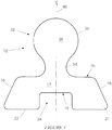
- Figure 1 of the accompanying drawings is an end view of a base 10 according to the invention.
- the base 10 includes an elongate body 12 of generally uniform cross-section which includes a bridging piece 14 which has a lower or first surface 18 and an opposed upper or second surface 20.
- first and second legs 22 and 24 respectively which define a gap 24 between them are located on the first surface.
- Respective outer sides 26 and 28 of the legs 22 and 24 slope outwardly away from each other, moving downwardly from the second surface.
- a retention component 32 is centrally positioned on the second surface 20.
- the retention component has a neck 34 and an enlarged formation 36 which is generally of circular cross-section and which forms a retention member 38.
- the body 12 is generally symmetrical about a centre line 40 which passes between the first leg 22 and the second leg 24 and through the retention component 32.
- the body 12 of the base can be formed in any suitable way e.g. in a moulding process or from a suitable extrusion which is cut to length as required.
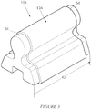
- the base has a length 42 (See Figure 3 ) which is suitably determined to accommodate the dimensions of a holder.
- the body 12 may be made from a non-ferrous metal e.g. aluminium, so that it is resistant to corrosion.
- the body is made from a hard plastics material, such as nylon, which is suitably reinforced. Other materials can be used.
- nylon is exemplary only.
- FIG 2 illustrates a conveyor belt scraper 44 which is made using the base 10 shown in Figure 1 .
- the body 12 is inserted into a suitable mould and, using an injection moulding process, a conveyor belt scraper element 46 is then over-moulded onto the base.
- the element 46 comprises a scraper member 48 which is made from polyurethane, a material which has properties which make it suitable for use in a scraping application.
- a leading edge 50 of the scraper member 48 defines a scraping surface.
- the leading edge 50 is formed with a slot 52, shown in dotted outline, to receive a scraper blade, (not shown), as is known in the art.
- the over-moulding process bonds the element 46 to the body 12 and thereby forms an integral scraper.
- a benefit of the construction described is that the body 12 is accurately formed and is not subjected to dimensional tolerances which typically are encountered when working with polyurethane. This means that, in use, the body 12 can be engaged with a suitable holder, using a sliding action, relatively easily. The "stickiness", or resistance to relative sliding movement typically associated with polyurethane, is avoided. Also, when the scraper member 48 has been worn and is to be replaced, removal of the scraper 44 from the holder can readily be accomplished.
- Figure 3 illustrates a base 10A wherein a body 12A of the base has a respective small step 54 at each of its opposed ends. However, the cross-sectional shape is otherwise maintained.
- the body 12A is designed to be used with a scraper element 56 of the shape shown in Figure 4 .
- the scraper element 56 has a scraper member 58 which terminates in a tip 60.
- a slot 62 formed into the tip accommodates a scraper blade (not shown) which is inserted and fixed in position using techniques which are known in the art.
- the scraper member 58 On opposed sides the scraper member 58 has two skirts 64 and 66 respectively which overlie outer sides of an injection-moulded nylon holder 68.
- the holder 68 is of complementary shape to the sloping sides 26 and 28, and to the undersides, of the legs 22 and 24. This allows the body 12A to be engaged with a sliding action with the holder, in a secure and effective manner, and to be disengaged from the holder, with similar ease, when required.
- the scraper element is not over-moulded onto the base but is separately formed and is engaged with the base when required.
- a tubular formation 70 which corresponds in shape to the cross-sectional shape of the retention member 38 of the body, extends through the scraper member 58.
- Voids 72 and 74 are formed on opposed sides of the neck 34 between opposing surfaces of the body 12A and of the scraper member 58. These voids allow the scraper member to be pivoted to a limited extent relative to the body, in one direction or the other, with the retention member 38, which is of generally circular outline, acting as a pivot or hinge axis.
- pivotal movement of the scraper element relative to the base can take place against a resisting compressive force of the respective insert.
- the small steps 54 at opposed ends of the body 12A define rebates. End cap, not shown, can be engaged with the rebates to seal an interior of the scraper (i.e. that portion of the scraper which accommodates the inserts) against the ingress of foreign material - this feature helps to counter wear and tear, and corrosion.
Landscapes
- Engineering & Computer Science (AREA)
- Mechanical Engineering (AREA)
- Chain Conveyers (AREA)
- Pusher Or Impeller Conveyors (AREA)
- Feeding Of Articles By Means Other Than Belts Or Rollers (AREA)
- Branching, Merging, And Special Transfer Between Conveyors (AREA)
- Paper (AREA)
- Framework For Endless Conveyors (AREA)
- Belt Conveyors (AREA)
Description
- This invention relates to a conveyor belt scraper which includes a base.
- One type of conveyor belt scraper is made from a tough resiliently deformable material such as polyurethane. Typically, this type of belt scraper, which is integrally moulded, has a retention formation which is engageable with a sliding action with a suitable channel in a holder. Some properties which make polyurethane suitable for use as a scraper can however present problems during installation and recovery of the scraper, when worn. This is because the polyurethane is "sticky" and tends to cling to a holder, resisting relative sliding movement.
- Another type of scraper has a base which is square in cross-section and which is positioned inside a tubular holder which is also of square cross-section. There is an offset between the base and the holder so that, inside the holder, four triangular voids are formed at respective corners of the holder. Each void is occupied by a compressible rubber insert. The positioning of each rubber insert can be arduous for it is necessary to freeze each insert, using liquid nitrogen, so that the insert can be placed in position. The use of liquid nitrogen is expensive and assembly of the scraper requires a fair amount of labour.
- WO 03//074393 discloses a scraper blade assembly including first and second sections, formed from a suitable elastomer such as polyurethane, secured together end-to-end by a location pin, the first section including means for securing a scraper blade to a scraper blade support structure and being adapted to be maintained in contact with a surface of a conveyor belt, the first and second sections having adjacent surfaces including at least one dovetailed tenon and a dovetail mortise which are arranged to be in interlocking mechanical arrangement after movement of the adjacent surfaces towards each other, the location pin extending through the sections to prevent withdrawal of the tenon from the mortise. Furthermore,
WO 03/074393 - The conveyor belt disclosed in
WO 03/074393 - An object of the present invention is to address, at least to some extent, the aforementioned factors.
- The invention provides a conveyor belt scraper which includes a base which includes an elongate body of uniform cross-section which includes a bridging piece with a first surface and a second surface which is opposed to the first surface, a retention component which is located on the second surface and, on the first surface, spaced apart first and second legs which define a gap between them with the features of claim 1.
- Preferably the retention component is centrally located on the second surface. In cross section the body may be symmetrical about a centre line which passes between the first and second legs and through the retention component.
- The retention component includes a neck which extends from the second surface and, at an end of the neck which is displaced from the second surface, the retention component may include a retention member which is larger in size than the neck.
- The retention member may be of an appropriate shape but preferably is substantially circular in cross-section.
- The body may be made from a material which allows the body to be slid into engagement with a holder, or to be slid out of engagement with a holder, with relative ease. The body may for example be made from a non-ferrous material (to counter the effects of corrosion) or from a plastics material e.g. a suitable nylon which is reinforced with glass or the like. This is exemplary only and non-limiting.
- The body may be formed from an extrusion which is cut, as appropriate, to a suitable length. Alternatively the body is formed in a moulding or other working process.
- The conveyor belt scraper may include a base of the aforementioned kind and, moulded to the body and thereby adhering to the body, a scraper element comprising a scraper member which terminates in a scraping end or which has provision for a scraping blade to be attached to it.
- The scraper member may be made from a material such as polyurethane which is more flexible (less rigid) than a material used in the body. Preferably the scraper member is integrally moulded over the body so that, for all practical purposes, a conveyor belt scraper of unitary integral construction is provided.
- The conveyor belt scraper may be one in which the scraper member is pivotally movable about an axis to a limited extent against a biasing action exerted by the respective insert which is resiliently compressed by such pivotal movement.
- The axis may be formed by, or pass through, the retentive member. Each insert is respectively positioned between a part of the second surface of the body and a part of a surface of the neck and an adjacent surface of the retention member.
- The invention is further described, by way of examples, with reference to the accompanying drawings in which:
-
Figure 1 is an end view of a base for a conveyor belt scraper according to the invention; -
Figure 2 illustrates a conveyor belt scraper which is made using a base of the kind shown inFigure 1 ; -
Figure 3 shows a slightly different form of the base of the invention in perspective; and -
Figure 4 illustrates how a scraper which includes the base shown inFigure 3 is mounted to a conveyor belt holder, in use. -
Figure 1 of the accompanying drawings is an end view of a base 10 according to the invention. - The base 10 includes an
elongate body 12 of generally uniform cross-section which includes abridging piece 14 which has a lower or first surface 18 and an opposed upper orsecond surface 20. - Spaced apart first and
second legs 22 and 24 respectively which define agap 24 between them are located on the first surface. Respectiveouter sides legs 22 and 24 slope outwardly away from each other, moving downwardly from the second surface. - A
retention component 32 is centrally positioned on thesecond surface 20. The retention component has aneck 34 and an enlargedformation 36 which is generally of circular cross-section and which forms aretention member 38. - The
body 12 is generally symmetrical about acentre line 40 which passes between the first leg 22 and thesecond leg 24 and through theretention component 32. - The
body 12 of the base can be formed in any suitable way e.g. in a moulding process or from a suitable extrusion which is cut to length as required. The base has a length 42 (SeeFigure 3 ) which is suitably determined to accommodate the dimensions of a holder. - The
body 12 may be made from a non-ferrous metal e.g. aluminium, so that it is resistant to corrosion. Preferably though the body is made from a hard plastics material, such as nylon, which is suitably reinforced. Other materials can be used. The use of nylon is exemplary only. -
Figure 2 illustrates aconveyor belt scraper 44 which is made using the base 10 shown inFigure 1 . Thebody 12 is inserted into a suitable mould and, using an injection moulding process, a conveyorbelt scraper element 46 is then over-moulded onto the base. Theelement 46 comprises ascraper member 48 which is made from polyurethane, a material which has properties which make it suitable for use in a scraping application. A leadingedge 50 of thescraper member 48 defines a scraping surface. Alternatively, the leadingedge 50 is formed with aslot 52, shown in dotted outline, to receive a scraper blade, (not shown), as is known in the art. - The over-moulding process bonds the
element 46 to thebody 12 and thereby forms an integral scraper. - A benefit of the construction described is that the
body 12 is accurately formed and is not subjected to dimensional tolerances which typically are encountered when working with polyurethane. This means that, in use, thebody 12 can be engaged with a suitable holder, using a sliding action, relatively easily. The "stickiness", or resistance to relative sliding movement typically associated with polyurethane, is avoided. Also, when thescraper member 48 has been worn and is to be replaced, removal of thescraper 44 from the holder can readily be accomplished. -
Figure 3 illustrates abase 10A wherein abody 12A of the base has a respectivesmall step 54 at each of its opposed ends. However, the cross-sectional shape is otherwise maintained. - The
body 12A is designed to be used with ascraper element 56 of the shape shown inFigure 4 . Thescraper element 56 has ascraper member 58 which terminates in atip 60. Aslot 62 formed into the tip accommodates a scraper blade (not shown) which is inserted and fixed in position using techniques which are known in the art. On opposed sides thescraper member 58 has twoskirts nylon holder 68. - The
holder 68 is of complementary shape to the slopingsides legs 22 and 24. This allows thebody 12A to be engaged with a sliding action with the holder, in a secure and effective manner, and to be disengaged from the holder, with similar ease, when required. - In this form of the invention the scraper element is not over-moulded onto the base but is separately formed and is engaged with the base when required. A
tubular formation 70 which corresponds in shape to the cross-sectional shape of theretention member 38 of the body, extends through thescraper member 58.Voids 72 and 74 are formed on opposed sides of theneck 34 between opposing surfaces of thebody 12A and of thescraper member 58. These voids allow the scraper member to be pivoted to a limited extent relative to the body, in one direction or the other, with theretention member 38, which is of generally circular outline, acting as a pivot or hinge axis. - In order for the pivotal movement to take place in a controlled manner rubber inserts 80 and 82 are respectively pushed into the
voids 72 and 74. To facilitate this, thescraper member 58 is pivoted in one direction to enlarge one void (72 or 74) and then the respective insert (80 or 82) is placed into the enlarged void. When the scraper member is moved in the opposing direction the insert (80 or 82), already in place, is compressed and when the other void (72 or 74) is sufficiently large, the other insert (80 or 82) is inserted. This technique also means that theinserts - In use of the scraper, pivotal movement of the scraper element relative to the base can take place against a resisting compressive force of the respective insert.
- The arrangement shown in
Figure 4 means that the use of the square base and holder and the use of liquid nitrogen referred to in the preamble hereof. - The
small steps 54 at opposed ends of thebody 12A define rebates. End cap, not shown, can be engaged with the rebates to seal an interior of the scraper (i.e. that portion of the scraper which accommodates the inserts) against the ingress of foreign material - this feature helps to counter wear and tear, and corrosion.
Claims (5)
- A conveyor belt scraper (44) which includes a base (10) which includes an elongate body (12) of uniform cross-section which includes a bridging piece (14) with a first surface (18) and a second surface (20) which is opposed to the first surface (18), a retention component (32) which is located on the second surface (20) and, on the first surface (18), spaced apart first and second legs (22,24) which define a gap (24) between them, wherein the retention component (32) includes a neck (34) which extends from the second surface (20) and, at an end of the neck (34) which is displaced from the second surface (20), the retention component (32) includes a retention member (38) which is larger in size than the neck (34) and a scraper element (56) comprising a scraper member (58) which includes an undercut recessed formation (70) which is engaged with the retention component (32) characterised in that, on respective opposed sides of the retention component (32), a respective resiliently compressible insert (80, 82) abuts the scraper member (58) and is positioned between the retention component (32) and an adjacent portion of the second surface (20) of the body (12).
- A conveyor belt scraper (44) according to claim 1 wherein in cross-section the body (12) is symmetrical about a centre line which passes between the first and second legs (22,24) and through the retention component (32).
- A conveyor belt scraper (44) according to claim 1 or 2 wherein the retention member (38) is substantially circular in cross-section.
- A conveyor belt scraper (44) according to any one of claims 1 to 3 wherein the body (12) is made from a non-ferrous material or from a reinforced nylon.
- A conveyor belt scraper (44) according to any one of claims 1 to 4 wherein the scraper member (58) is pivotally movable, about an axis formed by the retention member (38), to a limited extent against a biasing action exerted by the respective insert (80 or 82) which is resiliently compressed by such pivotal movement.
Priority Applications (1)
| Application Number | Priority Date | Filing Date | Title |
|---|---|---|---|
| PL16775060T PL3331784T3 (en) | 2015-08-04 | 2016-06-14 | Conveyor belt scraper |
Applications Claiming Priority (2)
| Application Number | Priority Date | Filing Date | Title |
|---|---|---|---|
| ZA2015/05592A ZA201505592B (en) | 2015-08-04 | 2015-08-04 | Conveyor belt scraper |
| PCT/ZA2016/050019 WO2017024323A1 (en) | 2015-08-04 | 2016-06-14 | Conveyor belt scraper |
Publications (2)
| Publication Number | Publication Date |
|---|---|
| EP3331784A1 EP3331784A1 (en) | 2018-06-13 |
| EP3331784B1 true EP3331784B1 (en) | 2020-03-18 |
Family
ID=57045434
Family Applications (1)
| Application Number | Title | Priority Date | Filing Date |
|---|---|---|---|
| EP16775060.3A Active EP3331784B1 (en) | 2015-08-04 | 2016-06-14 | Conveyor belt scraper |
Country Status (10)
| Country | Link |
|---|---|
| US (1) | US10233029B2 (en) |
| EP (1) | EP3331784B1 (en) |
| AU (1) | AU2016301200B2 (en) |
| CA (1) | CA2994727C (en) |
| CY (1) | CY1123009T1 (en) |
| ES (1) | ES2787132T3 (en) |
| PL (1) | PL3331784T3 (en) |
| PT (1) | PT3331784T (en) |
| WO (1) | WO2017024323A1 (en) |
| ZA (1) | ZA201505592B (en) |
Families Citing this family (2)
| Publication number | Priority date | Publication date | Assignee | Title |
|---|---|---|---|---|
| CN114180297B (en) * | 2020-09-15 | 2023-12-08 | 浙江浙能中煤舟山煤电有限责任公司 | Belt cleaner and belt conveyor applying same |
| WO2025065032A1 (en) * | 2023-09-21 | 2025-03-27 | Brelko Patents (Pty) Ltd | Conveyor belt scraper with torsion holder |
Family Cites Families (13)
| Publication number | Priority date | Publication date | Assignee | Title |
|---|---|---|---|---|
| GB2290276B (en) * | 1994-06-09 | 1998-03-04 | Slic Trading Co Limited | Belt scraper |
| US5865294A (en) * | 1998-05-06 | 1999-02-02 | Baker-Bohnert Rubber Co., Inc. | Scraper blade with a cavity to block debris build-up |
| US6315105B1 (en) * | 1999-06-22 | 2001-11-13 | Asgco Manufacturing, Inc. | Conveyor belt scraping apparatus |
| CA2463468C (en) * | 2001-12-20 | 2008-09-02 | Slic Trading Company Limited | Conveyor belt scraper |
| AUPS093002A0 (en) | 2002-03-06 | 2002-03-28 | O'grady, Trevor | Conveyor belt scraper blade assembly |
| US6926133B2 (en) * | 2003-03-27 | 2005-08-09 | Flexible Steel Lacing Company | Scraper blade for conveyor belts |
| US7007794B2 (en) * | 2004-07-29 | 2006-03-07 | Martin Engineering Company | Multiple durometer conveyor belt cleaner scraper blade |
| WO2008014342A2 (en) * | 2006-07-28 | 2008-01-31 | Flexible Steel Lacing Company | Reinforced cleaning blade and method of manufacturing thereof |
| US8875870B2 (en) * | 2011-03-31 | 2014-11-04 | Benetech, Inc. | Conveyor belt cleaner scraper blade and assembly |
| US8393459B2 (en) * | 2011-07-28 | 2013-03-12 | Martin Engineering Company | Conveyor belt scraper assembly comprising scraper members that are clamped together and method pertaining to the same |
| US9242805B2 (en) * | 2014-03-28 | 2016-01-26 | Flexible Steel Lacing Company | Scraper blade for conveyor belts |
| EP3154878B1 (en) * | 2014-06-12 | 2023-01-04 | Flexible Steel Lacing Company | Conveyor belt cleaner with removable cleaner assembly |
| US9738456B1 (en) * | 2016-08-02 | 2017-08-22 | Superior Industries, Inc. | Conveyor belt cleaner |
-
2015
- 2015-08-04 ZA ZA2015/05592A patent/ZA201505592B/en unknown
-
2016
- 2016-06-14 EP EP16775060.3A patent/EP3331784B1/en active Active
- 2016-06-14 PL PL16775060T patent/PL3331784T3/en unknown
- 2016-06-14 PT PT167750603T patent/PT3331784T/en unknown
- 2016-06-14 AU AU2016301200A patent/AU2016301200B2/en not_active Ceased
- 2016-06-14 US US15/750,016 patent/US10233029B2/en active Active
- 2016-06-14 ES ES16775060T patent/ES2787132T3/en active Active
- 2016-06-14 CA CA2994727A patent/CA2994727C/en active Active
- 2016-06-14 WO PCT/ZA2016/050019 patent/WO2017024323A1/en not_active Ceased
-
2020
- 2020-04-16 CY CY20201100362T patent/CY1123009T1/en unknown
Non-Patent Citations (1)
| Title |
|---|
| None * |
Also Published As
| Publication number | Publication date |
|---|---|
| US10233029B2 (en) | 2019-03-19 |
| US20180229943A1 (en) | 2018-08-16 |
| PL3331784T3 (en) | 2020-09-21 |
| ES2787132T3 (en) | 2020-10-14 |
| PT3331784T (en) | 2020-06-18 |
| AU2016301200A1 (en) | 2018-03-08 |
| ZA201505592B (en) | 2016-09-28 |
| AU2016301200B2 (en) | 2021-02-11 |
| CA2994727A1 (en) | 2017-02-09 |
| EP3331784A1 (en) | 2018-06-13 |
| CY1123009T1 (en) | 2021-10-29 |
| WO2017024323A1 (en) | 2017-02-09 |
| CA2994727C (en) | 2021-02-23 |
Similar Documents
| Publication | Publication Date | Title |
|---|---|---|
| EP3127839B1 (en) | Curvilinear support for chain conveyors | |
| US10327620B2 (en) | Squeegee | |
| AU2015235864A1 (en) | Scraper blade for conveyor belts | |
| US20100126832A1 (en) | Reinforced cleaning blade and method of manufacturing thereof | |
| KR20110009670A (en) | Windshield Wiper Device | |
| AU2016301200B2 (en) | Conveyor belt scraper | |
| KR101872928B1 (en) | Slicer | |
| EP3480142A1 (en) | Chain link, conveyor chain and conveyor apparatus | |
| US2973577A (en) | Windshield wiper blade trimming device | |
| EP3331785B1 (en) | Base for conveyor belt scraper | |
| CN108724116A (en) | Retainer | |
| EP2914519B1 (en) | Tapered scraper for a conveyor belt | |
| DE19600447C1 (en) | Knife with interchangeable blade | |
| US7527492B2 (en) | Device for rounding of dough pieces | |
| US20170320468A1 (en) | Fin ray-type wiper comprising a flexible structure optimized for demolding | |
| US20260077958A1 (en) | Conveyor belt scraper blade and a method for manufacturing the same | |
| DE29610901U1 (en) | Knives with spaced apart, resilient cutting surfaces with a common cutting edge or cutting blade | |
| EP4584189A1 (en) | Conveyor belt scraper blade and a method for manufacturing the same | |
| CN204307789U (en) | For keeping the device of blade element | |
| EP2495369B1 (en) | Snowplough blade | |
| EP2503083A1 (en) | Wearing element for a hinge and hinge provided with one or more wearing elements | |
| EP3715530A1 (en) | Cover for a floor opening near a curb stone | |
| US20040191024A1 (en) | Toggle bolt |
Legal Events
| Date | Code | Title | Description |
|---|---|---|---|
| STAA | Information on the status of an ep patent application or granted ep patent |
Free format text: STATUS: THE INTERNATIONAL PUBLICATION HAS BEEN MADE |
|
| PUAI | Public reference made under article 153(3) epc to a published international application that has entered the european phase |
Free format text: ORIGINAL CODE: 0009012 |
|
| STAA | Information on the status of an ep patent application or granted ep patent |
Free format text: STATUS: REQUEST FOR EXAMINATION WAS MADE |
|
| 17P | Request for examination filed |
Effective date: 20180214 |
|
| AK | Designated contracting states |
Kind code of ref document: A1 Designated state(s): AL AT BE BG CH CY CZ DE DK EE ES FI FR GB GR HR HU IE IS IT LI LT LU LV MC MK MT NL NO PL PT RO RS SE SI SK SM TR |
|
| AX | Request for extension of the european patent |
Extension state: BA ME |
|
| DAV | Request for validation of the european patent (deleted) | ||
| DAX | Request for extension of the european patent (deleted) | ||
| GRAP | Despatch of communication of intention to grant a patent |
Free format text: ORIGINAL CODE: EPIDOSNIGR1 |
|
| STAA | Information on the status of an ep patent application or granted ep patent |
Free format text: STATUS: GRANT OF PATENT IS INTENDED |
|
| INTG | Intention to grant announced |
Effective date: 20191009 |
|
| GRAS | Grant fee paid |
Free format text: ORIGINAL CODE: EPIDOSNIGR3 |
|
| GRAA | (expected) grant |
Free format text: ORIGINAL CODE: 0009210 |
|
| STAA | Information on the status of an ep patent application or granted ep patent |
Free format text: STATUS: THE PATENT HAS BEEN GRANTED |
|
| AK | Designated contracting states |
Kind code of ref document: B1 Designated state(s): AL AT BE BG CH CY CZ DE DK EE ES FI FR GB GR HR HU IE IS IT LI LT LU LV MC MK MT NL NO PL PT RO RS SE SI SK SM TR |
|
| REG | Reference to a national code |
Ref country code: GB Ref legal event code: FG4D |
|
| REG | Reference to a national code |
Ref country code: DE Ref legal event code: R096 Ref document number: 602016032117 Country of ref document: DE |
|
| REG | Reference to a national code |
Ref country code: CH Ref legal event code: NV Representative=s name: DR. LUSUARDI AG, CH Ref country code: AT Ref legal event code: REF Ref document number: 1245686 Country of ref document: AT Kind code of ref document: T Effective date: 20200415 Ref country code: IE Ref legal event code: FG4D |
|
| REG | Reference to a national code |
Ref country code: NL Ref legal event code: FP |
|
| REG | Reference to a national code |
Ref country code: PT Ref legal event code: SC4A Ref document number: 3331784 Country of ref document: PT Date of ref document: 20200618 Kind code of ref document: T Free format text: AVAILABILITY OF NATIONAL TRANSLATION Effective date: 20200609 |
|
| REG | Reference to a national code |
Ref country code: GR Ref legal event code: EP Ref document number: 20200401131 Country of ref document: GR Effective date: 20200615 |
|
| PG25 | Lapsed in a contracting state [announced via postgrant information from national office to epo] |
Ref country code: FI Free format text: LAPSE BECAUSE OF FAILURE TO SUBMIT A TRANSLATION OF THE DESCRIPTION OR TO PAY THE FEE WITHIN THE PRESCRIBED TIME-LIMIT Effective date: 20200318 Ref country code: RS Free format text: LAPSE BECAUSE OF FAILURE TO SUBMIT A TRANSLATION OF THE DESCRIPTION OR TO PAY THE FEE WITHIN THE PRESCRIBED TIME-LIMIT Effective date: 20200318 Ref country code: NO Free format text: LAPSE BECAUSE OF FAILURE TO SUBMIT A TRANSLATION OF THE DESCRIPTION OR TO PAY THE FEE WITHIN THE PRESCRIBED TIME-LIMIT Effective date: 20200618 |
|
| PG25 | Lapsed in a contracting state [announced via postgrant information from national office to epo] |
Ref country code: BG Free format text: LAPSE BECAUSE OF FAILURE TO SUBMIT A TRANSLATION OF THE DESCRIPTION OR TO PAY THE FEE WITHIN THE PRESCRIBED TIME-LIMIT Effective date: 20200618 Ref country code: SE Free format text: LAPSE BECAUSE OF FAILURE TO SUBMIT A TRANSLATION OF THE DESCRIPTION OR TO PAY THE FEE WITHIN THE PRESCRIBED TIME-LIMIT Effective date: 20200318 Ref country code: HR Free format text: LAPSE BECAUSE OF FAILURE TO SUBMIT A TRANSLATION OF THE DESCRIPTION OR TO PAY THE FEE WITHIN THE PRESCRIBED TIME-LIMIT Effective date: 20200318 Ref country code: LV Free format text: LAPSE BECAUSE OF FAILURE TO SUBMIT A TRANSLATION OF THE DESCRIPTION OR TO PAY THE FEE WITHIN THE PRESCRIBED TIME-LIMIT Effective date: 20200318 |
|
| REG | Reference to a national code |
Ref country code: LT Ref legal event code: MG4D |
|
| REG | Reference to a national code |
Ref country code: ES Ref legal event code: FG2A Ref document number: 2787132 Country of ref document: ES Kind code of ref document: T3 Effective date: 20201014 |
|
| PG25 | Lapsed in a contracting state [announced via postgrant information from national office to epo] |
Ref country code: IS Free format text: LAPSE BECAUSE OF FAILURE TO SUBMIT A TRANSLATION OF THE DESCRIPTION OR TO PAY THE FEE WITHIN THE PRESCRIBED TIME-LIMIT Effective date: 20200718 Ref country code: SK Free format text: LAPSE BECAUSE OF FAILURE TO SUBMIT A TRANSLATION OF THE DESCRIPTION OR TO PAY THE FEE WITHIN THE PRESCRIBED TIME-LIMIT Effective date: 20200318 Ref country code: EE Free format text: LAPSE BECAUSE OF FAILURE TO SUBMIT A TRANSLATION OF THE DESCRIPTION OR TO PAY THE FEE WITHIN THE PRESCRIBED TIME-LIMIT Effective date: 20200318 Ref country code: SM Free format text: LAPSE BECAUSE OF FAILURE TO SUBMIT A TRANSLATION OF THE DESCRIPTION OR TO PAY THE FEE WITHIN THE PRESCRIBED TIME-LIMIT Effective date: 20200318 Ref country code: LT Free format text: LAPSE BECAUSE OF FAILURE TO SUBMIT A TRANSLATION OF THE DESCRIPTION OR TO PAY THE FEE WITHIN THE PRESCRIBED TIME-LIMIT Effective date: 20200318 Ref country code: CZ Free format text: LAPSE BECAUSE OF FAILURE TO SUBMIT A TRANSLATION OF THE DESCRIPTION OR TO PAY THE FEE WITHIN THE PRESCRIBED TIME-LIMIT Effective date: 20200318 Ref country code: RO Free format text: LAPSE BECAUSE OF FAILURE TO SUBMIT A TRANSLATION OF THE DESCRIPTION OR TO PAY THE FEE WITHIN THE PRESCRIBED TIME-LIMIT Effective date: 20200318 |
|
| REG | Reference to a national code |
Ref country code: AT Ref legal event code: UEP Ref document number: 1245686 Country of ref document: AT Kind code of ref document: T Effective date: 20200318 |
|
| REG | Reference to a national code |
Ref country code: DE Ref legal event code: R097 Ref document number: 602016032117 Country of ref document: DE |
|
| PLBE | No opposition filed within time limit |
Free format text: ORIGINAL CODE: 0009261 |
|
| STAA | Information on the status of an ep patent application or granted ep patent |
Free format text: STATUS: NO OPPOSITION FILED WITHIN TIME LIMIT |
|
| PG25 | Lapsed in a contracting state [announced via postgrant information from national office to epo] |
Ref country code: DK Free format text: LAPSE BECAUSE OF FAILURE TO SUBMIT A TRANSLATION OF THE DESCRIPTION OR TO PAY THE FEE WITHIN THE PRESCRIBED TIME-LIMIT Effective date: 20200318 Ref country code: MC Free format text: LAPSE BECAUSE OF FAILURE TO SUBMIT A TRANSLATION OF THE DESCRIPTION OR TO PAY THE FEE WITHIN THE PRESCRIBED TIME-LIMIT Effective date: 20200318 |
|
| 26N | No opposition filed |
Effective date: 20201221 |
|
| PG25 | Lapsed in a contracting state [announced via postgrant information from national office to epo] |
Ref country code: LU Free format text: LAPSE BECAUSE OF NON-PAYMENT OF DUE FEES Effective date: 20200614 |
|
| PG25 | Lapsed in a contracting state [announced via postgrant information from national office to epo] |
Ref country code: SI Free format text: LAPSE BECAUSE OF FAILURE TO SUBMIT A TRANSLATION OF THE DESCRIPTION OR TO PAY THE FEE WITHIN THE PRESCRIBED TIME-LIMIT Effective date: 20200318 |
|
| PG25 | Lapsed in a contracting state [announced via postgrant information from national office to epo] |
Ref country code: MT Free format text: LAPSE BECAUSE OF FAILURE TO SUBMIT A TRANSLATION OF THE DESCRIPTION OR TO PAY THE FEE WITHIN THE PRESCRIBED TIME-LIMIT Effective date: 20200318 |
|
| PG25 | Lapsed in a contracting state [announced via postgrant information from national office to epo] |
Ref country code: MK Free format text: LAPSE BECAUSE OF FAILURE TO SUBMIT A TRANSLATION OF THE DESCRIPTION OR TO PAY THE FEE WITHIN THE PRESCRIBED TIME-LIMIT Effective date: 20200318 Ref country code: AL Free format text: LAPSE BECAUSE OF FAILURE TO SUBMIT A TRANSLATION OF THE DESCRIPTION OR TO PAY THE FEE WITHIN THE PRESCRIBED TIME-LIMIT Effective date: 20200318 |
|
| PGFP | Annual fee paid to national office [announced via postgrant information from national office to epo] |
Ref country code: IE Payment date: 20240617 Year of fee payment: 9 |
|
| PGFP | Annual fee paid to national office [announced via postgrant information from national office to epo] |
Ref country code: DE Payment date: 20240617 Year of fee payment: 9 |
|
| PGFP | Annual fee paid to national office [announced via postgrant information from national office to epo] |
Ref country code: GR Payment date: 20240617 Year of fee payment: 9 |
|
| PGFP | Annual fee paid to national office [announced via postgrant information from national office to epo] |
Ref country code: NL Payment date: 20240619 Year of fee payment: 9 |
|
| PGFP | Annual fee paid to national office [announced via postgrant information from national office to epo] |
Ref country code: AT Payment date: 20240617 Year of fee payment: 9 |
|
| PGFP | Annual fee paid to national office [announced via postgrant information from national office to epo] |
Ref country code: PL Payment date: 20240531 Year of fee payment: 9 Ref country code: PT Payment date: 20240529 Year of fee payment: 9 |
|
| PGFP | Annual fee paid to national office [announced via postgrant information from national office to epo] |
Ref country code: TR Payment date: 20240603 Year of fee payment: 9 |
|
| PGFP | Annual fee paid to national office [announced via postgrant information from national office to epo] |
Ref country code: IT Payment date: 20240628 Year of fee payment: 9 |
|
| PGFP | Annual fee paid to national office [announced via postgrant information from national office to epo] |
Ref country code: CH Payment date: 20240701 Year of fee payment: 9 Ref country code: ES Payment date: 20240718 Year of fee payment: 9 |
|
| PGFP | Annual fee paid to national office [announced via postgrant information from national office to epo] |
Ref country code: CY Payment date: 20240531 Year of fee payment: 9 |
|
| PGFP | Annual fee paid to national office [announced via postgrant information from national office to epo] |
Ref country code: GB Payment date: 20250526 Year of fee payment: 10 |
|
| PGFP | Annual fee paid to national office [announced via postgrant information from national office to epo] |
Ref country code: BE Payment date: 20250617 Year of fee payment: 10 |
|
| PGFP | Annual fee paid to national office [announced via postgrant information from national office to epo] |
Ref country code: FR Payment date: 20250624 Year of fee payment: 10 |
|
| REG | Reference to a national code |
Ref country code: DE Ref legal event code: R119 Ref document number: 602016032117 Country of ref document: DE |
|
| PG25 | Lapsed in a contracting state [announced via postgrant information from national office to epo] |
Ref country code: PT Free format text: LAPSE BECAUSE OF NON-PAYMENT OF DUE FEES Effective date: 20251215 |
|
| PG25 | Lapsed in a contracting state [announced via postgrant information from national office to epo] |
Ref country code: CY Free format text: LAPSE BECAUSE OF NON-PAYMENT OF DUE FEES Effective date: 20250614 |
|
| REG | Reference to a national code |
Ref country code: CH Ref legal event code: H13 Free format text: ST27 STATUS EVENT CODE: U-0-0-H10-H13 (AS PROVIDED BY THE NATIONAL OFFICE) Effective date: 20260127 |
|
| REG | Reference to a national code |
Ref country code: NL Ref legal event code: MM Effective date: 20250701 |
|
| REG | Reference to a national code |
Ref country code: AT Ref legal event code: MM01 Ref document number: 1245686 Country of ref document: AT Kind code of ref document: T Effective date: 20250614 |
|
| PG25 | Lapsed in a contracting state [announced via postgrant information from national office to epo] |
Ref country code: NL Free format text: LAPSE BECAUSE OF NON-PAYMENT OF DUE FEES Effective date: 20250701 |
|
| PG25 | Lapsed in a contracting state [announced via postgrant information from national office to epo] |
Ref country code: IE Free format text: LAPSE BECAUSE OF NON-PAYMENT OF DUE FEES Effective date: 20250614 Ref country code: DE Free format text: LAPSE BECAUSE OF NON-PAYMENT OF DUE FEES Effective date: 20260101 |
|
| PG25 | Lapsed in a contracting state [announced via postgrant information from national office to epo] |
Ref country code: AT Free format text: LAPSE BECAUSE OF NON-PAYMENT OF DUE FEES Effective date: 20250614 |
|
| PG25 | Lapsed in a contracting state [announced via postgrant information from national office to epo] |
Ref country code: IT Free format text: LAPSE BECAUSE OF NON-PAYMENT OF DUE FEES Effective date: 20250614 |
|
| PG25 | Lapsed in a contracting state [announced via postgrant information from national office to epo] |
Ref country code: CH Free format text: LAPSE BECAUSE OF NON-PAYMENT OF DUE FEES Effective date: 20250630 |
|
| PG25 | Lapsed in a contracting state [announced via postgrant information from national office to epo] |
Ref country code: GR Free format text: LAPSE BECAUSE OF NON-PAYMENT OF DUE FEES Effective date: 20260108 |