EP3331062A1 - Secondary battery - Google Patents
Secondary battery Download PDFInfo
- Publication number
- EP3331062A1 EP3331062A1 EP17204008.1A EP17204008A EP3331062A1 EP 3331062 A1 EP3331062 A1 EP 3331062A1 EP 17204008 A EP17204008 A EP 17204008A EP 3331062 A1 EP3331062 A1 EP 3331062A1
- Authority
- EP
- European Patent Office
- Prior art keywords
- secondary battery
- connecting portion
- main body
- electrode
- connecting piece
- Prior art date
- Legal status (The legal status is an assumption and is not a legal conclusion. Google has not performed a legal analysis and makes no representation as to the accuracy of the status listed.)
- Granted
Links
Images


Classifications
-
- H—ELECTRICITY
- H01—ELECTRIC ELEMENTS
- H01M—PROCESSES OR MEANS, e.g. BATTERIES, FOR THE DIRECT CONVERSION OF CHEMICAL ENERGY INTO ELECTRICAL ENERGY
- H01M50/00—Constructional details or processes of manufacture of the non-active parts of electrochemical cells other than fuel cells, e.g. hybrid cells
- H01M50/10—Primary casings; Jackets or wrappings
- H01M50/147—Lids or covers
-
- H—ELECTRICITY
- H01—ELECTRIC ELEMENTS
- H01M—PROCESSES OR MEANS, e.g. BATTERIES, FOR THE DIRECT CONVERSION OF CHEMICAL ENERGY INTO ELECTRICAL ENERGY
- H01M50/00—Constructional details or processes of manufacture of the non-active parts of electrochemical cells other than fuel cells, e.g. hybrid cells
- H01M50/50—Current conducting connections for cells or batteries
- H01M50/572—Means for preventing undesired use or discharge
- H01M50/574—Devices or arrangements for the interruption of current
- H01M50/578—Devices or arrangements for the interruption of current in response to pressure
-
- H—ELECTRICITY
- H01—ELECTRIC ELEMENTS
- H01M—PROCESSES OR MEANS, e.g. BATTERIES, FOR THE DIRECT CONVERSION OF CHEMICAL ENERGY INTO ELECTRICAL ENERGY
- H01M50/00—Constructional details or processes of manufacture of the non-active parts of electrochemical cells other than fuel cells, e.g. hybrid cells
- H01M50/10—Primary casings; Jackets or wrappings
- H01M50/172—Arrangements of electric connectors penetrating the casing
- H01M50/174—Arrangements of electric connectors penetrating the casing adapted for the shape of the cells
- H01M50/176—Arrangements of electric connectors penetrating the casing adapted for the shape of the cells for prismatic or rectangular cells
-
- H—ELECTRICITY
- H01—ELECTRIC ELEMENTS
- H01M—PROCESSES OR MEANS, e.g. BATTERIES, FOR THE DIRECT CONVERSION OF CHEMICAL ENERGY INTO ELECTRICAL ENERGY
- H01M50/00—Constructional details or processes of manufacture of the non-active parts of electrochemical cells other than fuel cells, e.g. hybrid cells
- H01M50/50—Current conducting connections for cells or batteries
- H01M50/531—Electrode connections inside a battery casing
- H01M50/536—Electrode connections inside a battery casing characterised by the method of fixing the leads to the electrodes, e.g. by welding
-
- H—ELECTRICITY
- H01—ELECTRIC ELEMENTS
- H01M—PROCESSES OR MEANS, e.g. BATTERIES, FOR THE DIRECT CONVERSION OF CHEMICAL ENERGY INTO ELECTRICAL ENERGY
- H01M2200/00—Safety devices for primary or secondary batteries
-
- H—ELECTRICITY
- H01—ELECTRIC ELEMENTS
- H01M—PROCESSES OR MEANS, e.g. BATTERIES, FOR THE DIRECT CONVERSION OF CHEMICAL ENERGY INTO ELECTRICAL ENERGY
- H01M50/00—Constructional details or processes of manufacture of the non-active parts of electrochemical cells other than fuel cells, e.g. hybrid cells
- H01M50/10—Primary casings; Jackets or wrappings
- H01M50/102—Primary casings; Jackets or wrappings characterised by their shape or physical structure
- H01M50/103—Primary casings; Jackets or wrappings characterised by their shape or physical structure prismatic or rectangular
-
- Y—GENERAL TAGGING OF NEW TECHNOLOGICAL DEVELOPMENTS; GENERAL TAGGING OF CROSS-SECTIONAL TECHNOLOGIES SPANNING OVER SEVERAL SECTIONS OF THE IPC; TECHNICAL SUBJECTS COVERED BY FORMER USPC CROSS-REFERENCE ART COLLECTIONS [XRACs] AND DIGESTS
- Y02—TECHNOLOGIES OR APPLICATIONS FOR MITIGATION OR ADAPTATION AGAINST CLIMATE CHANGE
- Y02E—REDUCTION OF GREENHOUSE GAS [GHG] EMISSIONS, RELATED TO ENERGY GENERATION, TRANSMISSION OR DISTRIBUTION
- Y02E60/00—Enabling technologies; Technologies with a potential or indirect contribution to GHG emissions mitigation
- Y02E60/10—Energy storage using batteries
Definitions
- the present invention relates to the field of battery, and particularly relates to a secondary battery.
- the secondary battery generally comprises an electrode assembly, a case receiving the electrode assembly and a cap plate, an electrode tab of the electrode assembly is fixed to an electrode terminal of the cap plate by welding (specifically, the electrode tab can be connected with the electrode terminal directly, and the electrode tab also can be connected with the electrode terminal via a connecting piece), then the electrode assembly is put into the case. But in an assembling process or a working process of the secondary battery, weld zones formed during welding will easily stab the electrode assembly or the electrode tab when the electrode assembly shakes, which affects the performance of the secondary battery.
- an isolating plate is generally provided between the weld zones and the electrode assembly for isolating the weld zones and the electrode assembly, but the installing process of the isolating plate is complex, and the isolating plate shakes easily during the working process of the secondary battery, so the isolating plate has poor stability and causes the failure of insulation.
- an object of the present invention is to provide a secondary battery, which can promote the safety performance and the energy density thereof.
- the present invention provides a secondary battery which comprises: a cap plate provided with a first electrode terminal and a second electrode terminal; an electrode assembly comprising a main body, a first electrode tab provided to the main body and a second electrode tab provided to the main body; and a first connecting piece connected between the first electrode tab and the first electrode terminal.
- the second electrode tab is electrically connected with the second electrode terminal.
- the first electrode tab includes a first connecting portion and a first bending portion, the first connecting portion is welded with the first connecting piece, and the first bending portion is bent downwardly and connected between the main body of the electrode assembly and the first connecting portion.
- the secondary battery further comprises a first insulating adhesive adhered on weld zones which are formed during welding of the first connecting portion and the first connecting piece and face the main body of the electrode assembly.
- the present invention has the following beneficial effects: in the secondary battery according to the present invention, the first insulating adhesive can cover the weld zones facing the main body of the electrode assembly, so the first insulating adhesive can isolate the weld zones from the main body or the first bending portion, and avoid the weld zones damaging the main body of the electrode assembly or the first bending portion in an assembling process and a working process of the secondary battery, thereby improving safety performance of the secondary battery.
- the first insulating adhesive is fixed to the weld zones by adhering, so the assembling process is simple and the stability is good; compared to the prior art, a thickness of the first insulating adhesive is small, thereby saving space and improving the energy density of the secondary battery.
- the first insulating adhesive also can avoid short circuit caused by contact between the weld zones and the main body of the electrode assembly.
- a secondary battery comprises: a cap plate 1 provided with a first electrode terminal 11 and a second electrode terminal 12 which are opposite in electrical polarity; an electrode assembly 2 comprising a main body 23, a first electrode tab 21 and a second electrode tab 22, the first electrode tab 21 and the second electrode tab 22 are provided to the main body 23 and opposite in electrical polarity; a first connecting piece 3 connected in series between the first electrode tab 21 and the first electrode terminal 11.
- the second electrode tab 22 is electrically connected with the second electrode terminal 12.
- the first electrode tab 21 includes a first connecting portion 211 and a first bending portion 212, the first connecting portion 211 is welded with the first connecting piece 3, and the first bending portion 212 is bent downwardly and connected between the main body 23 of the electrode assembly 2 and the first connecting portion 211.
- the secondary battery further comprises a first insulating adhesive S1 adhered on weld zones which are formed during welding of the first connecting portion 211 and the first connecting piece 3 and face the main body 23 of the electrode assembly 2.
- the first insulating adhesive S1 can cover the weld zones facing the main body 23 of the electrode assembly 2, so the first insulating adhesive S1 can isolate the weld zones from the main body 23 or the first bending portion 212, and avoid the weld zones damaging the main body 23 of the electrode assembly 2 or the first bending portion 212 in an assembling process and a working process of the secondary battery, thereby improving safety performance of the secondary battery.
- the first insulating adhesive S1 is fixed to the weld zones by adhering, so the assembling process is simple and the stability is good; compared to the prior art, a thickness of the first insulating adhesive S1 is small, thereby saving space and improving the energy density of the secondary battery.
- the first insulating adhesive S1 also can avoid short circuit caused by contact between the weld zones and the main body 23 of the electrode assembly 2 (that is an electrode plate of the main body 23 which is opposite to the first electrode tab 21 in electrical polarity).
- the welding can be laser welding, ultrasonic welding and the like
- the weld zones are uneven surfaces formed at two sides of welded portions in a height direction H
- the weld zones at a lower side in the height direction H face the main body 23 of the electrode assembly 2
- the first insulating adhesive S1 is adhered on the weld zones at the lower side in the height direction H.
- a second insulating adhesive S2 is adhered on an outside portion of the first bending portion 212.
- the first bending portion 212 will be pressed down and bent, and the outside portion of the first bending portion 212 will easily contact a later described case 6 and the main body 23 of the electrode assembly 2, thereby resulting in short circuit; however, it can avoid the outside portion of the first bending portion 212 contacting the case 6 and the main body 23 of the electrode assembly 2 by provision of the second insulating adhesive S2 adhered on the outside portion of the first bending portion 212, thereby preventing short circuit and improving the safety performance of the secondary battery.
- an angle between the first connecting portion 211 and the first bending portion 212 ranges from 85 degrees to 95 degrees.
- the first bending portion 212 extends nearly along the height direction H, so as to prevent the first bending portion 212 from being pressed down and bent, avoid the outside portion of the first bending portion 212 contacting the later described case 6 and the main body 23 of the electrode assembly 2.
- the angle between the first connecting portion 211 and the first bending portion 212 ranges from 0 degrees to 45 degrees. At this time, the first bending portion 212 nearly folds back onto the first connecting portion 211, thereby effectively reducing the space occupied by the first bending portion 212, and promoting a utilization rate of the space inside the secondary battery.
- the first connecting portion 211 is positioned below the first connecting piece 3 in the height direction H, and an upper surface of the first connecting portion 211 is securely connected with a lower surface of the first connecting piece 3.
- both a lower surface of the first connecting portion 211 and an upper surface of the first connecting piece 3 are formed with weld zones, and the first insulating adhesive S1 is provided on the weld zones in the lower surface of the first connecting portion 211.
- the first insulating adhesive S1 is adhered on the first connecting portion 211, and the first insulating adhesive S1 extends and covers an inside portion of the first connecting portion 211 and an inside portion of the first bending portion 212.
- the first insulating adhesive S1 is directly adhered on the first electrode tab 21 before the first electrode tab 21 is bent (the first electrode tab 21 forms the first connecting portion 211 and the first bending portion 212 after bent).
- the first connecting portion 211 is positioned above the first connecting piece 3 in the height direction H, and the lower surface of the first connecting portion 211 is securely connected with the upper surface of the first connecting piece 3.
- both the upper surface of the first connecting portion 211 and the lower surface of the first connecting piece 3 are formed with weld zones, and the first insulating adhesive S1 is provided on the weld zones in the lower surface of the first connecting piece 3.
- the first insulating adhesive S1 is adhered on the first connecting piece 3, and the first insulating adhesive S1 extends and covers the inside portion of the first bending portion 212.
- the secondary battery further comprises a first welding protecting piece 4 provided on the first connecting portion 211.
- the first welding protecting piece 4, the first connecting portion 211 and the first connecting piece 3 are securely connected together by ultrasonic welding; correspondingly, the first insulating adhesive S1 is adhered on the weld zones which are formed during the ultrasonic welding and face the main body 23 of the electrode assembly 2.
- the first welding protecting piece 4 can improve connection strength between the connecting section 211 and the first connecting piece 3.
- the first connecting portion 211 is fixed between the first welding protecting piece 4 and the first connecting piece 3, so the weld zones are formed in the first welding protecting piece 4 and the first connecting piece 3 after the ultrasonic welding, and the first insulating adhesive S1 is adhered on the weld zones facing the main body 23 of the electrode assembly 2.
- the secondary battery further comprises a case 6 and an insulating frame 7, the case 6 receives the electrode assembly 2 and is assembled with the cap plate 1, and the insulating frame 7 is received in the case 6 and isolates the cap plate 1 from the electrode assembly 2.
- Two ends of the insulating frame 7 in a width direction W are provided with side edges 71 extending downwardly, and two ends of the insulating frame 7 in a length direction L are provided with side edges 71 extending downwardly, all the side edges 71 can isolate the first electrode tab 21 and the second electrode tab 22 from the case 6, thereby avoiding the first electrode tab 21 and the second electrode tab 22 contacting the case 6 and preventing short circuit.
- the secondary battery further comprises a second connecting piece 5 connected in series between the second electrode terminal 12 and the second electrode tab 22.
- the second electrode tab 22 includes a second connecting portion 221 and a second bending portion 222, the second connecting portion 221 is welded with the second connecting piece 5, and the second bending portion 222 is bent downwardly and connected between the main body 23 of the electrode assembly 2 and the second connecting portion 221.
- a third insulating adhesive S3 is adhered on weld zones which are formed during welding of the second connecting portion 221 and the second connecting piece 5 and face the main body 23 of the electrode assembly 2.
- the third insulating adhesive S3 can cover the weld zones facing the main body 23 of the electrode assembly 2, so the third insulating adhesive S3 can isolate the weld zones from the main body 23 or the second bending portion 222, and avoid the weld zones damaging the main body 23 of the electrode assembly 2 or the second bending portion 222 in the assembling process and the working process of the secondary battery, thereby improving the safety performance of the secondary battery.
- the third insulating adhesive S3 is fixed to the weld zones by adhering, so the assembling process is simple and the stability is good; compared to the prior art, a thickness of the third insulating adhesive S3 is small, thereby saving space and improving the energy density of the secondary battery.
- the third insulating adhesive S3 also can avoid the short circuit caused by contact between the weld zones and the main body 23 of the electrode assembly 2 (that is an electrode plate of the main body 23 which is opposite to the second electrode tab 22 in electrical polarity).
- a fourth insulating adhesive S4 is adhered on an outside portion of the second bending portion 222.
- the second bending portion 222 will be pressed down and bent, and the outside portion of the second bending portion 222 may will easily contact the case 6 and the main body 23 of the electrode assembly 2, thereby resulting in short circuit; however, it can avoid the outside portion of the second bending portion 222 contacting the case 6 and the main body 23 of the electrode assembly 2 by provision of the fourth insulating adhesive S4 adhered on the outside portion of the second bending portion 222, thereby preventing short circuit and improving the safety performance of the secondary battery.
- an angle between the second connecting portion 221 and the second bending portion 222 ranges from 85 degrees to 95 degrees.
- the second bending portion 222 extends nearly along the height direction H, so as to prevent the second bending portion 222 from being pressed down and bent, avoid the outside portion of the second bending portion 222 contacting the case 6 and the main body 23 of the electrode assembly 2.
- the angle between the second connecting portion 221 and the second bending portion 222 ranges from 0 degrees to 45 degrees. At this time, the second bending portion 222 nearly folds back onto the second connecting portion 221, thereby effectively reducing the space occupied by the second bending portion 222, and promoting a utilization rate of the space inside the secondary battery.
- the second connecting portion 221 is positioned below the second connecting piece 5 in the height direction H and an upper surface of the second connecting portion 221 is securely connected with a lower surface of the second connecting piece 5.
- both a lower surface of the second connecting portion 221 and an upper surface of the second connecting piece 5 are formed with weld zones, and the third insulating adhesive S3 is provided on the weld zones in the lower surface of the second connecting portion 221.
- the third insulating adhesive S3 is adhered on the second connecting portion 221, and the third insulating adhesive S3 extends and covers an inside portion of the second connecting portion 221 and an inside portion of the second bending portion 222.
- the third insulating adhesive S3 is directly adhered on the second electrode tab 22 before the second electrode tab 22 is bent (the second electrode tab 22 forms the second connecting portion 221 and the second bending portion 222 after bent).
- the second connecting portion 221 is positioned above the second connecting piece 5 in the height direction H, and the lower surface of the second connecting portion 221 is securely connected with the upper surface of the second connecting piece 5.
- both the upper surface of the second connecting portion 221 and the lower surface of the second connecting piece 5 are formed with weld zones, and the third insulating adhesive S3 is provided on the weld zones in the lower surface of the second connecting piece 5.
- the third insulating adhesive S3 is adhered on the second connecting piece 5, and the third insulating adhesive S3 extends and covers the inside portion of the second bending portion 222.
- the secondary battery further comprises a second welding protecting piece 8 provided on the second connecting portion 221.
- the second welding protecting piece 8, the second connecting portion 221 and the second connecting piece 5 are securely connected together by ultrasonic welding; correspondingly, the third insulating adhesive S3 is adhered on the weld zones which are formed during the ultrasonic welding and face the main body 23 of the electrode assembly 2.
- the second welding protecting piece 8 can improve connection strength between the second connecting portion 221 and the second connecting piece 5.
- the second connecting portion 221 is fixed between the second welding protecting piece 8 and the second connecting piece 5, so the weld zones are formed in the second welding protecting piece 8 and the second connecting piece 5 after the ultrasonic welding, and the third insulating adhesive S3 is adhered on the weld zones facing the main body 23 of the electrode assembly 2.
Landscapes
- Chemical & Material Sciences (AREA)
- Chemical Kinetics & Catalysis (AREA)
- Electrochemistry (AREA)
- General Chemical & Material Sciences (AREA)
- Connection Of Batteries Or Terminals (AREA)
Abstract
Description
- The present application claims priority to Chinese patent application No.
201621319939.5, filed on December 02, 2016 - The present invention relates to the field of battery, and particularly relates to a secondary battery.
- The secondary battery generally comprises an electrode assembly, a case receiving the electrode assembly and a cap plate, an electrode tab of the electrode assembly is fixed to an electrode terminal of the cap plate by welding (specifically, the electrode tab can be connected with the electrode terminal directly, and the electrode tab also can be connected with the electrode terminal via a connecting piece), then the electrode assembly is put into the case. But in an assembling process or a working process of the secondary battery, weld zones formed during welding will easily stab the electrode assembly or the electrode tab when the electrode assembly shakes, which affects the performance of the secondary battery.
- In prior art, an isolating plate is generally provided between the weld zones and the electrode assembly for isolating the weld zones and the electrode assembly, but the installing process of the isolating plate is complex, and the isolating plate shakes easily during the working process of the secondary battery, so the isolating plate has poor stability and causes the failure of insulation.
- In view of the problem existing in the background, an object of the present invention is to provide a secondary battery, which can promote the safety performance and the energy density thereof.
- In order to achieve the above object, the present invention provides a secondary battery which comprises: a cap plate provided with a first electrode terminal and a second electrode terminal; an electrode assembly comprising a main body, a first electrode tab provided to the main body and a second electrode tab provided to the main body; and a first connecting piece connected between the first electrode tab and the first electrode terminal. The second electrode tab is electrically connected with the second electrode terminal. The first electrode tab includes a first connecting portion and a first bending portion, the first connecting portion is welded with the first connecting piece, and the first bending portion is bent downwardly and connected between the main body of the electrode assembly and the first connecting portion. The secondary battery further comprises a first insulating adhesive adhered on weld zones which are formed during welding of the first connecting portion and the first connecting piece and face the main body of the electrode assembly.
- The present invention has the following beneficial effects: in the secondary battery according to the present invention, the first insulating adhesive can cover the weld zones facing the main body of the electrode assembly, so the first insulating adhesive can isolate the weld zones from the main body or the first bending portion, and avoid the weld zones damaging the main body of the electrode assembly or the first bending portion in an assembling process and a working process of the secondary battery, thereby improving safety performance of the secondary battery. At the same time, the first insulating adhesive is fixed to the weld zones by adhering, so the assembling process is simple and the stability is good; compared to the prior art, a thickness of the first insulating adhesive is small, thereby saving space and improving the energy density of the secondary battery. Moreover, the first insulating adhesive also can avoid short circuit caused by contact between the weld zones and the main body of the electrode assembly.
-
-
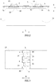
FIG. 1 is a schematic view of a secondary battery according to the present invention. -
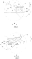
FIG. 2 is another schematic view of the secondary battery according to the present invention with a case removed. -
FIG. 3 is still another schematic view of the secondary battery according to the present invention. -
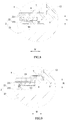
FIGs. 4-6 are schematic views of different embodiments of a first electrode tab of the secondary battery according to the present invention. -
FIGs. 7-9 are schematic views of different embodiments of a second electrode tab of the secondary battery according to the present invention. - Reference numerals in figures are represented as follows:
- 1 cap plate
- 11 first electrode terminal
- 12 second electrode terminal
- 2 electrode assembly
- 21 first electrode tab
- 211 first connecting portion
- 212 first bending portion
- 22 second electrode tab
- 221 second connecting portion
- 222 second bending portion
- 23 main body
- 21 first electrode tab
- 3 first connecting piece
- 4 first welding protecting piece
- 5 second connecting piece
- 6 case
- 7 insulating frame
- 71 side edge
- 8 second welding protecting piece
- S1 first insulating adhesive
- S2 second insulating adhesive
- S3 third insulating adhesive
- S4 fourth insulating adhesive
- L length direction
- H height direction
- W width direction
- Hereinafter a secondary battery according to the present invention will be described in detail in combination with the figures.
- Referring to
FIGs. 1-9 , a secondary battery according to the present invention comprises: acap plate 1 provided with afirst electrode terminal 11 and asecond electrode terminal 12 which are opposite in electrical polarity; anelectrode assembly 2 comprising amain body 23, afirst electrode tab 21 and asecond electrode tab 22, thefirst electrode tab 21 and thesecond electrode tab 22 are provided to themain body 23 and opposite in electrical polarity; a first connectingpiece 3 connected in series between thefirst electrode tab 21 and thefirst electrode terminal 11. Thesecond electrode tab 22 is electrically connected with thesecond electrode terminal 12. Thefirst electrode tab 21 includes a first connectingportion 211 and afirst bending portion 212, the first connectingportion 211 is welded with the first connectingpiece 3, and thefirst bending portion 212 is bent downwardly and connected between themain body 23 of theelectrode assembly 2 and the first connectingportion 211. The secondary battery further comprises a first insulating adhesive S1 adhered on weld zones which are formed during welding of the first connectingportion 211 and the first connectingpiece 3 and face themain body 23 of theelectrode assembly 2. - In the secondary battery according to the present invention, the first insulating adhesive S1 can cover the weld zones facing the
main body 23 of theelectrode assembly 2, so the first insulating adhesive S1 can isolate the weld zones from themain body 23 or thefirst bending portion 212, and avoid the weld zones damaging themain body 23 of theelectrode assembly 2 or thefirst bending portion 212 in an assembling process and a working process of the secondary battery, thereby improving safety performance of the secondary battery. At the same time, the first insulating adhesive S1 is fixed to the weld zones by adhering, so the assembling process is simple and the stability is good; compared to the prior art, a thickness of the first insulating adhesive S1 is small, thereby saving space and improving the energy density of the secondary battery. Moreover, the first insulating adhesive S1 also can avoid short circuit caused by contact between the weld zones and themain body 23 of the electrode assembly 2 (that is an electrode plate of themain body 23 which is opposite to thefirst electrode tab 21 in electrical polarity). - In the secondary battery according to the present invention, the welding can be laser welding, ultrasonic welding and the like, the weld zones are uneven surfaces formed at two sides of welded portions in a height direction H, the weld zones at a lower side in the height direction H face the
main body 23 of theelectrode assembly 2, and the first insulating adhesive S1 is adhered on the weld zones at the lower side in the height direction H. - In the secondary battery according to the present invention, referring to
FIG. 1 ,FIG. 4 ,FIG. 5 andFIG. 6 , a second insulating adhesive S2 is adhered on an outside portion of thefirst bending portion 212. In the assembling process of the secondary battery, in order to improve the energy density of the secondary battery, thefirst bending portion 212 will be pressed down and bent, and the outside portion of thefirst bending portion 212 will easily contact a later describedcase 6 and themain body 23 of theelectrode assembly 2, thereby resulting in short circuit; however, it can avoid the outside portion of thefirst bending portion 212 contacting thecase 6 and themain body 23 of theelectrode assembly 2 by provision of the second insulating adhesive S2 adhered on the outside portion of thefirst bending portion 212, thereby preventing short circuit and improving the safety performance of the secondary battery. - In the secondary battery according to the present invention, referring to
FIG. 6 , an angle between the first connectingportion 211 and thefirst bending portion 212 ranges from 85 degrees to 95 degrees. At this time, thefirst bending portion 212 extends nearly along the height direction H, so as to prevent thefirst bending portion 212 from being pressed down and bent, avoid the outside portion of thefirst bending portion 212 contacting the later describedcase 6 and themain body 23 of theelectrode assembly 2. - In the secondary battery according to the present invention, referring to
FIG. 4 and FIG. 5 , the angle between the first connectingportion 211 and thefirst bending portion 212 ranges from 0 degrees to 45 degrees. At this time, thefirst bending portion 212 nearly folds back onto the first connectingportion 211, thereby effectively reducing the space occupied by thefirst bending portion 212, and promoting a utilization rate of the space inside the secondary battery. - In the secondary battery according to the present invention, referring to
FIG. 4 , the first connectingportion 211 is positioned below the first connectingpiece 3 in the height direction H, and an upper surface of the first connectingportion 211 is securely connected with a lower surface of the first connectingpiece 3. At this time, both a lower surface of the first connectingportion 211 and an upper surface of the first connectingpiece 3 are formed with weld zones, and the first insulating adhesive S1 is provided on the weld zones in the lower surface of the first connectingportion 211. - In the secondary battery according to the present invention, referring to
FIG. 4 , the first insulating adhesive S1 is adhered on the first connectingportion 211, and the first insulating adhesive S1 extends and covers an inside portion of the first connectingportion 211 and an inside portion of thefirst bending portion 212. Referring toFIG. 3 , the first insulating adhesive S1 is directly adhered on thefirst electrode tab 21 before thefirst electrode tab 21 is bent (thefirst electrode tab 21 forms the first connectingportion 211 and thefirst bending portion 212 after bent). - In the secondary battery according to the present invention, referring to
FIG. 5 , the first connectingportion 211 is positioned above the first connectingpiece 3 in the height direction H, and the lower surface of the first connectingportion 211 is securely connected with the upper surface of the first connectingpiece 3. At this time, both the upper surface of the first connectingportion 211 and the lower surface of the first connectingpiece 3 are formed with weld zones, and the first insulating adhesive S1 is provided on the weld zones in the lower surface of the first connectingpiece 3. - In the secondary battery according to the present invention, referring to
FIG. 5 , the first insulating adhesive S1 is adhered on the first connectingpiece 3, and the first insulating adhesive S1 extends and covers the inside portion of thefirst bending portion 212. - In the secondary battery according to the present invention, referring to
FIG. 1 ,FIG. 4 ,FIG. 5 andFIG. 6 , the secondary battery further comprises a firstwelding protecting piece 4 provided on the first connectingportion 211. The firstwelding protecting piece 4, the first connectingportion 211 and the first connectingpiece 3 are securely connected together by ultrasonic welding; correspondingly, the first insulating adhesive S1 is adhered on the weld zones which are formed during the ultrasonic welding and face themain body 23 of theelectrode assembly 2. The firstwelding protecting piece 4 can improve connection strength between the connectingsection 211 and the first connectingpiece 3. The first connectingportion 211 is fixed between the firstwelding protecting piece 4 and the first connectingpiece 3, so the weld zones are formed in the firstwelding protecting piece 4 and the first connectingpiece 3 after the ultrasonic welding, and the first insulating adhesive S1 is adhered on the weld zones facing themain body 23 of theelectrode assembly 2. - In the secondary battery according to the present invention, referring to
FIG. 1 , the secondary battery further comprises acase 6 and an insulatingframe 7, thecase 6 receives theelectrode assembly 2 and is assembled with thecap plate 1, and the insulatingframe 7 is received in thecase 6 and isolates thecap plate 1 from theelectrode assembly 2. Two ends of the insulatingframe 7 in a width direction W are provided withside edges 71 extending downwardly, and two ends of the insulatingframe 7 in a length direction L are provided withside edges 71 extending downwardly, all the side edges 71 can isolate thefirst electrode tab 21 and thesecond electrode tab 22 from thecase 6, thereby avoiding thefirst electrode tab 21 and thesecond electrode tab 22 contacting thecase 6 and preventing short circuit. - In the secondary battery according to the present invention, referring to
FIGs. 7-9 , the secondary battery further comprises a second connectingpiece 5 connected in series between thesecond electrode terminal 12 and thesecond electrode tab 22. Thesecond electrode tab 22 includes a second connectingportion 221 and asecond bending portion 222, the second connectingportion 221 is welded with the second connectingpiece 5, and thesecond bending portion 222 is bent downwardly and connected between themain body 23 of theelectrode assembly 2 and the second connectingportion 221. A third insulating adhesive S3 is adhered on weld zones which are formed during welding of the second connectingportion 221 and the second connectingpiece 5 and face themain body 23 of theelectrode assembly 2. - In the secondary battery according to the present invention, the third insulating adhesive S3 can cover the weld zones facing the
main body 23 of theelectrode assembly 2, so the third insulating adhesive S3 can isolate the weld zones from themain body 23 or thesecond bending portion 222, and avoid the weld zones damaging themain body 23 of theelectrode assembly 2 or thesecond bending portion 222 in the assembling process and the working process of the secondary battery, thereby improving the safety performance of the secondary battery. At the same time, the third insulating adhesive S3 is fixed to the weld zones by adhering, so the assembling process is simple and the stability is good; compared to the prior art, a thickness of the third insulating adhesive S3 is small, thereby saving space and improving the energy density of the secondary battery. Moreover, the third insulating adhesive S3 also can avoid the short circuit caused by contact between the weld zones and themain body 23 of the electrode assembly 2 (that is an electrode plate of themain body 23 which is opposite to thesecond electrode tab 22 in electrical polarity). - In the secondary battery according to the present invention, referring to
FIGs. 7-9 , a fourth insulating adhesive S4 is adhered on an outside portion of thesecond bending portion 222. In the assembling process of the secondary battery, in order to improve the energy density of the secondary battery, thesecond bending portion 222 will be pressed down and bent, and the outside portion of thesecond bending portion 222 may will easily contact thecase 6 and themain body 23 of theelectrode assembly 2, thereby resulting in short circuit; however, it can avoid the outside portion of thesecond bending portion 222 contacting thecase 6 and themain body 23 of theelectrode assembly 2 by provision of the fourth insulating adhesive S4 adhered on the outside portion of thesecond bending portion 222, thereby preventing short circuit and improving the safety performance of the secondary battery. - In the secondary battery according to the present invention, referring to
FIG. 9 , an angle between the second connectingportion 221 and thesecond bending portion 222 ranges from 85 degrees to 95 degrees. At this time, thesecond bending portion 222 extends nearly along the height direction H, so as to prevent thesecond bending portion 222 from being pressed down and bent, avoid the outside portion of thesecond bending portion 222 contacting thecase 6 and themain body 23 of theelectrode assembly 2. - In the secondary battery according to the present invention, referring to
FIG. 7 andFIG. 8 , the angle between the second connectingportion 221 and thesecond bending portion 222 ranges from 0 degrees to 45 degrees. At this time, thesecond bending portion 222 nearly folds back onto the second connectingportion 221, thereby effectively reducing the space occupied by thesecond bending portion 222, and promoting a utilization rate of the space inside the secondary battery. - In the secondary battery according to the present invention, referring to
FIG. 7 , the second connectingportion 221 is positioned below the second connectingpiece 5 in the height direction H and an upper surface of the second connectingportion 221 is securely connected with a lower surface of the second connectingpiece 5. At this time, both a lower surface of the second connectingportion 221 and an upper surface of the second connectingpiece 5 are formed with weld zones, and the third insulating adhesive S3 is provided on the weld zones in the lower surface of the second connectingportion 221. - In the secondary battery according to the present invention, referring to
FIG. 7 , the third insulating adhesive S3 is adhered on the second connectingportion 221, and the third insulating adhesive S3 extends and covers an inside portion of the second connectingportion 221 and an inside portion of thesecond bending portion 222. Referring toFIG. 3 , the third insulating adhesive S3 is directly adhered on thesecond electrode tab 22 before thesecond electrode tab 22 is bent (thesecond electrode tab 22 forms the second connectingportion 221 and thesecond bending portion 222 after bent). - In the secondary battery according to the present invention, referring to
FIG. 8 , the second connectingportion 221 is positioned above the second connectingpiece 5 in the height direction H, and the lower surface of the second connectingportion 221 is securely connected with the upper surface of the second connectingpiece 5. At this time, both the upper surface of the second connectingportion 221 and the lower surface of the second connectingpiece 5 are formed with weld zones, and the third insulating adhesive S3 is provided on the weld zones in the lower surface of the second connectingpiece 5. - In the secondary battery according to the present invention, referring to
FIG. 8 , the third insulating adhesive S3 is adhered on the second connectingpiece 5, and the third insulating adhesive S3 extends and covers the inside portion of thesecond bending portion 222. - In the secondary battery according to the present invention, referring to
FIG. 1 ,FIG. 7 ,FIG. 8 and FIG. 9 , the secondary battery further comprises a secondwelding protecting piece 8 provided on the second connectingportion 221. The secondwelding protecting piece 8, the second connectingportion 221 and the second connectingpiece 5 are securely connected together by ultrasonic welding; correspondingly, the third insulating adhesive S3 is adhered on the weld zones which are formed during the ultrasonic welding and face themain body 23 of theelectrode assembly 2. The secondwelding protecting piece 8 can improve connection strength between the second connectingportion 221 and the second connectingpiece 5. The second connectingportion 221 is fixed between the secondwelding protecting piece 8 and the second connectingpiece 5, so the weld zones are formed in the secondwelding protecting piece 8 and the second connectingpiece 5 after the ultrasonic welding, and the third insulating adhesive S3 is adhered on the weld zones facing themain body 23 of theelectrode assembly 2.
Claims (11)
- A secondary battery, comprising:a cap plate provided with a first electrode terminal and a second electrode terminal;an electrode assembly comprising a main body, a first electrode tab provided to the main body and a second electrode tab provided to the main body; anda first connecting piece connected between the first electrode tab and the first electrode terminal;the second electrode tab being electrically connected with the second electrode terminal;whereinthe first electrode tab includes a first connecting portion and a first bending portion, the first connecting portion is welded with the first connecting piece, and the first bending portion is bent downwardly and connected between the main body of the electrode assembly and the first connecting portion;the secondary battery further comprises a first insulating adhesive adhered on weld zones which are formed during welding of the first connecting portion and the first connecting piece and face the main body of the electrode assembly.
- The secondary battery according to Claim 1, wherein
the secondary battery further comprises a second insulating adhesive adhered on an outside portion of the first bending portion. - The secondary battery according to Claim 1, wherein
an angle between the first connecting portion and the first bending portion ranges from 85 degrees to 95 degrees; or
an angle between the first connecting portion and the first bending portion ranges from 0 degrees to 45 degrees. - The secondary battery according to Claim 1, wherein
the first connecting portion is positioned below the first connecting piece in a height direction, and an upper surface of the first connecting portion is securely connected with a lower surface of the first connecting piece. - The secondary battery according to Claim 4, wherein
the first insulating adhesive is adhered on the first connecting portion, and the first insulating adhesive extends and covers an inside portion of the first connecting portion and an inside portion of the first bending portion. - The secondary battery according to Claim 1, wherein
the first connecting portion is positioned above the first connecting piece in a height direction, and a lower surface of the first connecting portion is securely connected with an upper surface of the first connecting piece. - The secondary battery according to Claim 6, wherein
the first insulating adhesive is adhered on the first connecting piece, and the first insulating adhesive extends and covers the inside portion of the first bending portion. - The secondary battery according to Claim 4, wherein
the secondary battery further comprises a first welding protecting piece provided on the first connecting portion;
the first welding protecting piece, the first connecting portion and the first connecting piece are securely connected together by ultrasonic welding;
the first insulating adhesive is adhered on the weld zones which are formed during the ultrasonic welding and face the main body of the electrode assembly. - The secondary battery according to Claim 6, wherein
the secondary battery further comprises a first welding protecting piece provided on the first connecting portion;
the first welding protecting piece, the first connecting portion and the first connecting piece are securely connected together by ultrasonic welding;
the first insulating adhesive is adhered on the weld zones which are formed during the ultrasonic welding and face the main body of the electrode assembly. - The secondary battery according to Claim 1, wherein
the secondary battery further comprises a case and an insulating frame, the case receives the electrode assembly and is assembled with the cap plate, and the insulating frame is received in the case and isolates the cap plate from the electrode assembly;
two ends of the insulating frame in a width direction are provided with side edges extending downwardly, and two ends of the insulating frame in a length direction are provided with side edges extending downwardly, all the side edges isolate the first electrode tab and the second electrode tab from the case. - The secondary battery according to Claim 1, wherein
the secondary battery further comprises a second connecting piece connected between the second electrode terminal and the second electrode tab;
the second electrode tab includes a second connecting portion and a second bending portion, the second connecting portion is welded with the second connecting piece, and the second bending portion is bent downwardly and connected between the main body of the electrode assembly and the second connecting portion;
the secondary battery further comprises a third insulating adhesive adhered on weld zones which are formed during welding of the second connecting portion and the second connecting piece and face the main body of the electrode assembly.
Applications Claiming Priority (1)
| Application Number | Priority Date | Filing Date | Title |
|---|---|---|---|
| CN201621319939.5U CN206250261U (en) | 2016-12-02 | 2016-12-02 | Secondary cell |
Publications (2)
| Publication Number | Publication Date |
|---|---|
| EP3331062A1 true EP3331062A1 (en) | 2018-06-06 |
| EP3331062B1 EP3331062B1 (en) | 2024-05-29 |
Family
ID=59003289
Family Applications (1)
| Application Number | Title | Priority Date | Filing Date |
|---|---|---|---|
| EP17204008.1A Active EP3331062B1 (en) | 2016-12-02 | 2017-11-28 | Secondary battery |
Country Status (6)
| Country | Link |
|---|---|
| US (2) | US10586971B2 (en) |
| EP (1) | EP3331062B1 (en) |
| CN (1) | CN206250261U (en) |
| ES (1) | ES2988520T3 (en) |
| HU (1) | HUE067831T2 (en) |
| PL (1) | PL3331062T3 (en) |
Cited By (4)
| Publication number | Priority date | Publication date | Assignee | Title |
|---|---|---|---|---|
| EP3940882A1 (en) * | 2020-07-15 | 2022-01-19 | China Lithium Battery Technology Co., Limited | Battery and manufacturing method of battery |
| EP4283731A3 (en) * | 2022-05-25 | 2024-03-20 | REPT BATTERO Energy Co., Ltd. | Top cover structure of secondary battery, top cover assembly and secondary battery |
| EP3989352B1 (en) | 2020-01-17 | 2024-08-21 | Contemporary Amperex Technology Co., Limited | Secondary battery, battery module, and device using battery as power supply |
| EP4589757A4 (en) * | 2023-08-08 | 2026-04-08 | Eve Power Co Ltd | TAB-HELD STRUCTURE, BATTERY MODULE AND BATTERY PACK |
Families Citing this family (16)
| Publication number | Priority date | Publication date | Assignee | Title |
|---|---|---|---|---|
| CN109698385B (en) * | 2017-10-20 | 2024-06-18 | 宁德时代新能源科技股份有限公司 | Secondary battery |
| CN207818809U (en) * | 2017-12-14 | 2018-09-04 | 比亚迪股份有限公司 | Battery and battery pack having same, electric vehicle |
| CN108428921A (en) | 2018-02-01 | 2018-08-21 | 宁德时代新能源科技股份有限公司 | Secondary battery |
| CN108511639A (en) * | 2018-03-08 | 2018-09-07 | 四川西丹孚能源科技有限公司 | Directly draw the power battery head cover of formula downhand welding structure based on lug |
| CN110556500A (en) * | 2018-05-31 | 2019-12-10 | 比亚迪股份有限公司 | Lithium ion secondary battery assembly, preparation method thereof and lithium ion secondary battery |
| WO2020218217A1 (en) * | 2019-04-25 | 2020-10-29 | 株式会社村田製作所 | Secondary battery |
| CN111029490A (en) * | 2019-11-28 | 2020-04-17 | 欣旺达电动汽车电池有限公司 | Single battery and power battery pack |
| CN111140581A (en) * | 2020-01-11 | 2020-05-12 | 苏州炬鸿通讯电脑科技有限公司 | A connection structure of a soft connector and a lower insulating pad based on a buckle structure |
| CN112192014B (en) * | 2020-10-19 | 2023-02-24 | 厦门海辰储能科技股份有限公司 | Welding jig, conductive welding sheet in-position detection device and detection method |
| CN115732819B (en) * | 2021-08-27 | 2023-12-15 | 宁德时代新能源科技股份有限公司 | Battery monomer and battery, device, preparation method and preparation device related to battery monomer |
| WO2023050162A1 (en) | 2021-09-29 | 2023-04-06 | 宁德时代新能源科技股份有限公司 | Battery cell, battery, electric device, and method and device for manufacturing battery cell |
| JP7685587B2 (en) * | 2021-09-30 | 2025-05-29 | 香港時代新能源科技有限公司 | Battery cells, batteries, power consumption devices, and battery cell manufacturing methods and devices |
| CN115172998A (en) * | 2022-07-26 | 2022-10-11 | 上海兰钧新能源科技有限公司 | Secondary battery and method for manufacturing secondary battery |
| CN115189077B (en) * | 2022-09-06 | 2023-01-17 | 楚能新能源股份有限公司 | A square battery cell, an assembly method of the square battery cell, and a battery module |
| JP7684933B2 (en) * | 2022-09-07 | 2025-05-28 | プライムプラネットエナジー&ソリューションズ株式会社 | battery |
| CN222653985U (en) * | 2024-03-18 | 2025-03-21 | 欣旺达动力科技股份有限公司 | Single battery and battery pack |
Citations (5)
| Publication number | Priority date | Publication date | Assignee | Title |
|---|---|---|---|---|
| US20030232243A1 (en) * | 2002-06-12 | 2003-12-18 | Ji-Jun Hong | Method for treating electrode tabs of crude cell for lithium secondary battery, and crude cell and lithium secondary battery according to the method |
| US20120034513A1 (en) * | 2010-08-05 | 2012-02-09 | Samsung Sdi Co., Ltd. | Secondary battery |
| JP2013161686A (en) * | 2012-02-06 | 2013-08-19 | Toyota Industries Corp | Electricity storage device and vehicle |
| JP2015032549A (en) * | 2013-08-06 | 2015-02-16 | 株式会社豊田自動織機 | Power storage device |
| US20150243960A1 (en) * | 2012-10-24 | 2015-08-27 | Toyota Jidosha Kabushiki Kaisha | Secondary battery comprising current interrupt device |
Family Cites Families (3)
| Publication number | Priority date | Publication date | Assignee | Title |
|---|---|---|---|---|
| KR101094039B1 (en) | 2009-10-01 | 2011-12-19 | 삼성에스디아이 주식회사 | Current blocking device and secondary battery having same |
| CN102208594B (en) | 2010-03-30 | 2015-04-29 | 三星Sdi株式会社 | Secondary battery |
| CN205429058U (en) | 2016-03-18 | 2016-08-03 | 宁德时代新能源科技股份有限公司 | Secondary battery |
-
2016
- 2016-12-02 CN CN201621319939.5U patent/CN206250261U/en active Active
-
2017
- 2017-11-17 US US15/816,975 patent/US10586971B2/en active Active
- 2017-11-28 EP EP17204008.1A patent/EP3331062B1/en active Active
- 2017-11-28 PL PL17204008.1T patent/PL3331062T3/en unknown
- 2017-11-28 ES ES17204008T patent/ES2988520T3/en active Active
- 2017-11-28 HU HUE17204008A patent/HUE067831T2/en unknown
-
2019
- 2019-12-09 US US16/708,242 patent/US11121436B2/en active Active
Patent Citations (5)
| Publication number | Priority date | Publication date | Assignee | Title |
|---|---|---|---|---|
| US20030232243A1 (en) * | 2002-06-12 | 2003-12-18 | Ji-Jun Hong | Method for treating electrode tabs of crude cell for lithium secondary battery, and crude cell and lithium secondary battery according to the method |
| US20120034513A1 (en) * | 2010-08-05 | 2012-02-09 | Samsung Sdi Co., Ltd. | Secondary battery |
| JP2013161686A (en) * | 2012-02-06 | 2013-08-19 | Toyota Industries Corp | Electricity storage device and vehicle |
| US20150243960A1 (en) * | 2012-10-24 | 2015-08-27 | Toyota Jidosha Kabushiki Kaisha | Secondary battery comprising current interrupt device |
| JP2015032549A (en) * | 2013-08-06 | 2015-02-16 | 株式会社豊田自動織機 | Power storage device |
Cited By (5)
| Publication number | Priority date | Publication date | Assignee | Title |
|---|---|---|---|---|
| EP3989352B1 (en) | 2020-01-17 | 2024-08-21 | Contemporary Amperex Technology Co., Limited | Secondary battery, battery module, and device using battery as power supply |
| US12463297B2 (en) | 2020-01-17 | 2025-11-04 | Contemporary Amperex Technology (Hong Kong) Limited | Secondary battery, battery module, and device using battery as power supply |
| EP3940882A1 (en) * | 2020-07-15 | 2022-01-19 | China Lithium Battery Technology Co., Limited | Battery and manufacturing method of battery |
| EP4283731A3 (en) * | 2022-05-25 | 2024-03-20 | REPT BATTERO Energy Co., Ltd. | Top cover structure of secondary battery, top cover assembly and secondary battery |
| EP4589757A4 (en) * | 2023-08-08 | 2026-04-08 | Eve Power Co Ltd | TAB-HELD STRUCTURE, BATTERY MODULE AND BATTERY PACK |
Also Published As
| Publication number | Publication date |
|---|---|
| US10586971B2 (en) | 2020-03-10 |
| US20200119327A1 (en) | 2020-04-16 |
| CN206250261U (en) | 2017-06-13 |
| EP3331062B1 (en) | 2024-05-29 |
| HUE067831T2 (en) | 2024-11-28 |
| PL3331062T3 (en) | 2024-09-23 |
| ES2988520T3 (en) | 2024-11-20 |
| US20180159108A1 (en) | 2018-06-07 |
| US11121436B2 (en) | 2021-09-14 |
Similar Documents
| Publication | Publication Date | Title |
|---|---|---|
| EP3331062B1 (en) | Secondary battery | |
| US11811017B2 (en) | Battery unit and battery module | |
| US11557816B2 (en) | Secondary battery | |
| US10573872B2 (en) | Secondary battery | |
| CN206250229U (en) | secondary battery | |
| CN105870366B (en) | Power battery top cap and power battery | |
| US10601023B2 (en) | Secondary battery and assembly therefor | |
| JP6438248B2 (en) | Secondary battery | |
| JPWO2014024802A1 (en) | Storage device manufacturing method, auxiliary plate for ultrasonic welding, and storage device | |
| EP3255696B1 (en) | Top cover of power battery and power battery | |
| US11482748B2 (en) | Battery cap assembly and secondary battery | |
| US9755196B2 (en) | Rechargeable battery including current collecting member with current collecting part having twisted surface | |
| CN205666262U (en) | Power battery top cap and power battery | |
| KR102361704B1 (en) | Rechargeable battery | |
| KR101132146B1 (en) | Prismatic Battery of Excellent Adherence | |
| CN205666260U (en) | Power battery top cap and power battery thereof | |
| JP2016110958A (en) | Secondary battery | |
| JP2004164985A (en) | Prismatic battery and method for manufacturing the same | |
| JP2002170553A (en) | Prismatic battery | |
| JP2016115434A (en) | Power storage element |
Legal Events
| Date | Code | Title | Description |
|---|---|---|---|
| PUAI | Public reference made under article 153(3) epc to a published international application that has entered the european phase |
Free format text: ORIGINAL CODE: 0009012 |
|
| STAA | Information on the status of an ep patent application or granted ep patent |
Free format text: STATUS: REQUEST FOR EXAMINATION WAS MADE |
|
| 17P | Request for examination filed |
Effective date: 20171128 |
|
| AK | Designated contracting states |
Kind code of ref document: A1 Designated state(s): AL AT BE BG CH CY CZ DE DK EE ES FI FR GB GR HR HU IE IS IT LI LT LU LV MC MK MT NL NO PL PT RO RS SE SI SK SM TR |
|
| AX | Request for extension of the european patent |
Extension state: BA ME |
|
| STAA | Information on the status of an ep patent application or granted ep patent |
Free format text: STATUS: EXAMINATION IS IN PROGRESS |
|
| 17Q | First examination report despatched |
Effective date: 20200408 |
|
| REG | Reference to a national code |
Ref country code: DE Ref legal event code: R079 Free format text: PREVIOUS MAIN CLASS: H01M0002200000 Ipc: H01M0050103000 Ref country code: DE Ref legal event code: R079 Ref document number: 602017082250 Country of ref document: DE Free format text: PREVIOUS MAIN CLASS: H01M0002200000 Ipc: H01M0050103000 |
|
| GRAP | Despatch of communication of intention to grant a patent |
Free format text: ORIGINAL CODE: EPIDOSNIGR1 |
|
| STAA | Information on the status of an ep patent application or granted ep patent |
Free format text: STATUS: GRANT OF PATENT IS INTENDED |
|
| RIC1 | Information provided on ipc code assigned before grant |
Ipc: H01M 50/536 20210101ALI20240205BHEP Ipc: H01M 50/176 20210101ALI20240205BHEP Ipc: H01M 50/578 20210101ALI20240205BHEP Ipc: H01M 50/147 20210101ALI20240205BHEP Ipc: H01M 50/103 20210101AFI20240205BHEP |
|
| INTG | Intention to grant announced |
Effective date: 20240228 |
|
| GRAS | Grant fee paid |
Free format text: ORIGINAL CODE: EPIDOSNIGR3 |
|
| GRAA | (expected) grant |
Free format text: ORIGINAL CODE: 0009210 |
|
| STAA | Information on the status of an ep patent application or granted ep patent |
Free format text: STATUS: THE PATENT HAS BEEN GRANTED |
|
| AK | Designated contracting states |
Kind code of ref document: B1 Designated state(s): AL AT BE BG CH CY CZ DE DK EE ES FI FR GB GR HR HU IE IS IT LI LT LU LV MC MK MT NL NO PL PT RO RS SE SI SK SM TR |
|
| REG | Reference to a national code |
Ref country code: CH Ref legal event code: EP |
|
| REG | Reference to a national code |
Ref country code: IE Ref legal event code: FG4D |
|
| REG | Reference to a national code |
Ref country code: DE Ref legal event code: R096 Ref document number: 602017082250 Country of ref document: DE |
|
| REG | Reference to a national code |
Ref country code: DE Ref legal event code: R081 Ref document number: 602017082250 Country of ref document: DE Owner name: CONTEMPORARY AMPEREX TECHNOLOGY (HONG KONG) LT, HK Free format text: FORMER OWNER: CONTEMPORARY AMPEREX TECHNOLOGY CO., LTD., NINGDE, FUJIAN, CN |
|
| REG | Reference to a national code |
Ref country code: NL Ref legal event code: PD Owner name: CONTEMPORARY AMPEREX TECHNOLOGY (HONG KONG) LIMITED; CN Free format text: DETAILS ASSIGNMENT: CHANGE OF OWNER(S), ASSIGNMENT; FORMER OWNER NAME: CONTEMPORARY AMPEREX TECHNOLOGY CO., LIMITED Effective date: 20240819 Ref country code: NL Ref legal event code: FP Ref country code: GB Ref legal event code: 732E Free format text: REGISTERED BETWEEN 20240801 AND 20240807 |
|
| REG | Reference to a national code |
Ref country code: SE Ref legal event code: TRGR |
|
| REG | Reference to a national code |
Ref country code: LT Ref legal event code: MG9D |
|
| REG | Reference to a national code |
Ref country code: HU Ref legal event code: GB9C Owner name: CONTEMPORARY AMPEREX TECHNOLOGY (HONG KONG) LIMITED, HK Free format text: FORMER OWNER(S): CONTEMPORARY AMPEREX TECHNOLOGY CO., LIMITED, CN Ref country code: HU Ref legal event code: FH1C Free format text: FORMER REPRESENTATIVE(S): DANUBIA SZABADALMI ES JOGI IRODA KFT., HU Representative=s name: DANUBIA SZABADALMI ES JOGI IRODA KFT., HU |
|
| RAP2 | Party data changed (patent owner data changed or rights of a patent transferred) |
Owner name: CONTEMPORARY AMPEREX TECHNOLOGY(HONG KONG) LIMITED |
|
| PG25 | Lapsed in a contracting state [announced via postgrant information from national office to epo] |
Ref country code: IS Free format text: LAPSE BECAUSE OF FAILURE TO SUBMIT A TRANSLATION OF THE DESCRIPTION OR TO PAY THE FEE WITHIN THE PRESCRIBED TIME-LIMIT Effective date: 20240929 |
|
| PG25 | Lapsed in a contracting state [announced via postgrant information from national office to epo] |
Ref country code: BG Free format text: LAPSE BECAUSE OF FAILURE TO SUBMIT A TRANSLATION OF THE DESCRIPTION OR TO PAY THE FEE WITHIN THE PRESCRIBED TIME-LIMIT Effective date: 20240529 |
|
| PG25 | Lapsed in a contracting state [announced via postgrant information from national office to epo] |
Ref country code: HR Free format text: LAPSE BECAUSE OF FAILURE TO SUBMIT A TRANSLATION OF THE DESCRIPTION OR TO PAY THE FEE WITHIN THE PRESCRIBED TIME-LIMIT Effective date: 20240529 Ref country code: FI Free format text: LAPSE BECAUSE OF FAILURE TO SUBMIT A TRANSLATION OF THE DESCRIPTION OR TO PAY THE FEE WITHIN THE PRESCRIBED TIME-LIMIT Effective date: 20240529 |
|
| PG25 | Lapsed in a contracting state [announced via postgrant information from national office to epo] |
Ref country code: GR Free format text: LAPSE BECAUSE OF FAILURE TO SUBMIT A TRANSLATION OF THE DESCRIPTION OR TO PAY THE FEE WITHIN THE PRESCRIBED TIME-LIMIT Effective date: 20240830 |
|
| REG | Reference to a national code |
Ref country code: AT Ref legal event code: MK05 Ref document number: 1691414 Country of ref document: AT Kind code of ref document: T Effective date: 20240529 |
|
| PG25 | Lapsed in a contracting state [announced via postgrant information from national office to epo] |
Ref country code: AT Free format text: LAPSE BECAUSE OF FAILURE TO SUBMIT A TRANSLATION OF THE DESCRIPTION OR TO PAY THE FEE WITHIN THE PRESCRIBED TIME-LIMIT Effective date: 20240529 |
|
| PG25 | Lapsed in a contracting state [announced via postgrant information from national office to epo] |
Ref country code: LV Free format text: LAPSE BECAUSE OF FAILURE TO SUBMIT A TRANSLATION OF THE DESCRIPTION OR TO PAY THE FEE WITHIN THE PRESCRIBED TIME-LIMIT Effective date: 20240529 |
|
| PG25 | Lapsed in a contracting state [announced via postgrant information from national office to epo] |
Ref country code: NO Free format text: LAPSE BECAUSE OF FAILURE TO SUBMIT A TRANSLATION OF THE DESCRIPTION OR TO PAY THE FEE WITHIN THE PRESCRIBED TIME-LIMIT Effective date: 20240829 Ref country code: LV Free format text: LAPSE BECAUSE OF FAILURE TO SUBMIT A TRANSLATION OF THE DESCRIPTION OR TO PAY THE FEE WITHIN THE PRESCRIBED TIME-LIMIT Effective date: 20240529 Ref country code: IS Free format text: LAPSE BECAUSE OF FAILURE TO SUBMIT A TRANSLATION OF THE DESCRIPTION OR TO PAY THE FEE WITHIN THE PRESCRIBED TIME-LIMIT Effective date: 20240929 Ref country code: HR Free format text: LAPSE BECAUSE OF FAILURE TO SUBMIT A TRANSLATION OF THE DESCRIPTION OR TO PAY THE FEE WITHIN THE PRESCRIBED TIME-LIMIT Effective date: 20240529 Ref country code: GR Free format text: LAPSE BECAUSE OF FAILURE TO SUBMIT A TRANSLATION OF THE DESCRIPTION OR TO PAY THE FEE WITHIN THE PRESCRIBED TIME-LIMIT Effective date: 20240830 Ref country code: FI Free format text: LAPSE BECAUSE OF FAILURE TO SUBMIT A TRANSLATION OF THE DESCRIPTION OR TO PAY THE FEE WITHIN THE PRESCRIBED TIME-LIMIT Effective date: 20240529 Ref country code: BG Free format text: LAPSE BECAUSE OF FAILURE TO SUBMIT A TRANSLATION OF THE DESCRIPTION OR TO PAY THE FEE WITHIN THE PRESCRIBED TIME-LIMIT Effective date: 20240529 Ref country code: AT Free format text: LAPSE BECAUSE OF FAILURE TO SUBMIT A TRANSLATION OF THE DESCRIPTION OR TO PAY THE FEE WITHIN THE PRESCRIBED TIME-LIMIT Effective date: 20240529 Ref country code: RS Free format text: LAPSE BECAUSE OF FAILURE TO SUBMIT A TRANSLATION OF THE DESCRIPTION OR TO PAY THE FEE WITHIN THE PRESCRIBED TIME-LIMIT Effective date: 20240829 |
|
| REG | Reference to a national code |
Ref country code: ES Ref legal event code: FG2A Ref document number: 2988520 Country of ref document: ES Kind code of ref document: T3 Effective date: 20241120 |
|
| REG | Reference to a national code |
Ref country code: HU Ref legal event code: AG4A Ref document number: E067831 Country of ref document: HU |
|
| PG25 | Lapsed in a contracting state [announced via postgrant information from national office to epo] |
Ref country code: DK Free format text: LAPSE BECAUSE OF FAILURE TO SUBMIT A TRANSLATION OF THE DESCRIPTION OR TO PAY THE FEE WITHIN THE PRESCRIBED TIME-LIMIT Effective date: 20240529 |
|
| PG25 | Lapsed in a contracting state [announced via postgrant information from national office to epo] |
Ref country code: EE Free format text: LAPSE BECAUSE OF FAILURE TO SUBMIT A TRANSLATION OF THE DESCRIPTION OR TO PAY THE FEE WITHIN THE PRESCRIBED TIME-LIMIT Effective date: 20240529 |
|
| PG25 | Lapsed in a contracting state [announced via postgrant information from national office to epo] |
Ref country code: CZ Free format text: LAPSE BECAUSE OF FAILURE TO SUBMIT A TRANSLATION OF THE DESCRIPTION OR TO PAY THE FEE WITHIN THE PRESCRIBED TIME-LIMIT Effective date: 20240529 |
|
| PG25 | Lapsed in a contracting state [announced via postgrant information from national office to epo] |
Ref country code: SK Free format text: LAPSE BECAUSE OF FAILURE TO SUBMIT A TRANSLATION OF THE DESCRIPTION OR TO PAY THE FEE WITHIN THE PRESCRIBED TIME-LIMIT Effective date: 20240529 Ref country code: RO Free format text: LAPSE BECAUSE OF FAILURE TO SUBMIT A TRANSLATION OF THE DESCRIPTION OR TO PAY THE FEE WITHIN THE PRESCRIBED TIME-LIMIT Effective date: 20240529 |
|
| PG25 | Lapsed in a contracting state [announced via postgrant information from national office to epo] |
Ref country code: SM Free format text: LAPSE BECAUSE OF FAILURE TO SUBMIT A TRANSLATION OF THE DESCRIPTION OR TO PAY THE FEE WITHIN THE PRESCRIBED TIME-LIMIT Effective date: 20240529 |
|
| PG25 | Lapsed in a contracting state [announced via postgrant information from national office to epo] |
Ref country code: SM Free format text: LAPSE BECAUSE OF FAILURE TO SUBMIT A TRANSLATION OF THE DESCRIPTION OR TO PAY THE FEE WITHIN THE PRESCRIBED TIME-LIMIT Effective date: 20240529 Ref country code: SK Free format text: LAPSE BECAUSE OF FAILURE TO SUBMIT A TRANSLATION OF THE DESCRIPTION OR TO PAY THE FEE WITHIN THE PRESCRIBED TIME-LIMIT Effective date: 20240529 Ref country code: RO Free format text: LAPSE BECAUSE OF FAILURE TO SUBMIT A TRANSLATION OF THE DESCRIPTION OR TO PAY THE FEE WITHIN THE PRESCRIBED TIME-LIMIT Effective date: 20240529 Ref country code: EE Free format text: LAPSE BECAUSE OF FAILURE TO SUBMIT A TRANSLATION OF THE DESCRIPTION OR TO PAY THE FEE WITHIN THE PRESCRIBED TIME-LIMIT Effective date: 20240529 Ref country code: DK Free format text: LAPSE BECAUSE OF FAILURE TO SUBMIT A TRANSLATION OF THE DESCRIPTION OR TO PAY THE FEE WITHIN THE PRESCRIBED TIME-LIMIT Effective date: 20240529 Ref country code: CZ Free format text: LAPSE BECAUSE OF FAILURE TO SUBMIT A TRANSLATION OF THE DESCRIPTION OR TO PAY THE FEE WITHIN THE PRESCRIBED TIME-LIMIT Effective date: 20240529 |
|
| PG25 | Lapsed in a contracting state [announced via postgrant information from national office to epo] |
Ref country code: IT Free format text: LAPSE BECAUSE OF FAILURE TO SUBMIT A TRANSLATION OF THE DESCRIPTION OR TO PAY THE FEE WITHIN THE PRESCRIBED TIME-LIMIT Effective date: 20240529 |
|
| REG | Reference to a national code |
Ref country code: DE Ref legal event code: R097 Ref document number: 602017082250 Country of ref document: DE |
|
| PLBE | No opposition filed within time limit |
Free format text: ORIGINAL CODE: 0009261 |
|
| STAA | Information on the status of an ep patent application or granted ep patent |
Free format text: STATUS: NO OPPOSITION FILED WITHIN TIME LIMIT |
|
| PG25 | Lapsed in a contracting state [announced via postgrant information from national office to epo] |
Ref country code: SI Free format text: LAPSE BECAUSE OF FAILURE TO SUBMIT A TRANSLATION OF THE DESCRIPTION OR TO PAY THE FEE WITHIN THE PRESCRIBED TIME-LIMIT Effective date: 20240529 |
|
| 26N | No opposition filed |
Effective date: 20250303 |
|
| REG | Reference to a national code |
Ref country code: CH Ref legal event code: PL |
|
| PG25 | Lapsed in a contracting state [announced via postgrant information from national office to epo] |
Ref country code: MC Free format text: LAPSE BECAUSE OF FAILURE TO SUBMIT A TRANSLATION OF THE DESCRIPTION OR TO PAY THE FEE WITHIN THE PRESCRIBED TIME-LIMIT Effective date: 20240529 |
|
| PG25 | Lapsed in a contracting state [announced via postgrant information from national office to epo] |
Ref country code: LU Free format text: LAPSE BECAUSE OF NON-PAYMENT OF DUE FEES Effective date: 20241128 |
|
| REG | Reference to a national code |
Ref country code: CH Ref legal event code: PL |
|
| PG25 | Lapsed in a contracting state [announced via postgrant information from national office to epo] |
Ref country code: CH Free format text: LAPSE BECAUSE OF NON-PAYMENT OF DUE FEES Effective date: 20241130 |
|
| REG | Reference to a national code |
Ref country code: BE Ref legal event code: MM Effective date: 20241130 |
|
| PG25 | Lapsed in a contracting state [announced via postgrant information from national office to epo] |
Ref country code: BE Free format text: LAPSE BECAUSE OF NON-PAYMENT OF DUE FEES Effective date: 20241130 |
|
| PG25 | Lapsed in a contracting state [announced via postgrant information from national office to epo] |
Ref country code: IE Free format text: LAPSE BECAUSE OF NON-PAYMENT OF DUE FEES Effective date: 20241128 |
|
| PGFP | Annual fee paid to national office [announced via postgrant information from national office to epo] |
Ref country code: HU Payment date: 20251107 Year of fee payment: 9 |
|
| PGFP | Annual fee paid to national office [announced via postgrant information from national office to epo] |
Ref country code: NL Payment date: 20251127 Year of fee payment: 9 |
|
| PGFP | Annual fee paid to national office [announced via postgrant information from national office to epo] |
Ref country code: DE Payment date: 20251124 Year of fee payment: 9 |
|
| PGFP | Annual fee paid to national office [announced via postgrant information from national office to epo] |
Ref country code: GB Payment date: 20251126 Year of fee payment: 9 |
|
| PGFP | Annual fee paid to national office [announced via postgrant information from national office to epo] |
Ref country code: FR Payment date: 20251128 Year of fee payment: 9 |
|
| PGFP | Annual fee paid to national office [announced via postgrant information from national office to epo] |
Ref country code: SE Payment date: 20251127 Year of fee payment: 9 |
|
| PGFP | Annual fee paid to national office [announced via postgrant information from national office to epo] |
Ref country code: PL Payment date: 20251103 Year of fee payment: 9 |
|
| PGFP | Annual fee paid to national office [announced via postgrant information from national office to epo] |
Ref country code: ES Payment date: 20251202 Year of fee payment: 9 |
|
| PG25 | Lapsed in a contracting state [announced via postgrant information from national office to epo] |
Ref country code: PT Free format text: LAPSE BECAUSE OF NON-PAYMENT OF DUE FEES Effective date: 20240529 |
|
| PG25 | Lapsed in a contracting state [announced via postgrant information from national office to epo] |
Ref country code: CY Free format text: LAPSE BECAUSE OF FAILURE TO SUBMIT A TRANSLATION OF THE DESCRIPTION OR TO PAY THE FEE WITHIN THE PRESCRIBED TIME-LIMIT; INVALID AB INITIO Effective date: 20171128 |