EP3330946A1 - Vehicle periphery information management device - Google Patents
Vehicle periphery information management device Download PDFInfo
- Publication number
- EP3330946A1 EP3330946A1 EP16832754.2A EP16832754A EP3330946A1 EP 3330946 A1 EP3330946 A1 EP 3330946A1 EP 16832754 A EP16832754 A EP 16832754A EP 3330946 A1 EP3330946 A1 EP 3330946A1
- Authority
- EP
- European Patent Office
- Prior art keywords
- vehicle
- information
- data
- region
- periphery
- Prior art date
- Legal status (The legal status is an assumption and is not a legal conclusion. Google has not performed a legal analysis and makes no representation as to the accuracy of the status listed.)
- Granted
Links
Images






Classifications
-
- G—PHYSICS
- G06—COMPUTING OR CALCULATING; COUNTING
- G06V—IMAGE OR VIDEO RECOGNITION OR UNDERSTANDING
- G06V20/00—Scenes; Scene-specific elements
- G06V20/50—Context or environment of the image
- G06V20/56—Context or environment of the image exterior to a vehicle by using sensors mounted on the vehicle
-
- G—PHYSICS
- G06—COMPUTING OR CALCULATING; COUNTING
- G06T—IMAGE DATA PROCESSING OR GENERATION, IN GENERAL
- G06T1/00—General purpose image data processing
-
- G—PHYSICS
- G06—COMPUTING OR CALCULATING; COUNTING
- G06V—IMAGE OR VIDEO RECOGNITION OR UNDERSTANDING
- G06V20/00—Scenes; Scene-specific elements
- G06V20/50—Context or environment of the image
- G06V20/56—Context or environment of the image exterior to a vehicle by using sensors mounted on the vehicle
- G06V20/58—Recognition of moving objects or obstacles, e.g. vehicles or pedestrians; Recognition of traffic objects, e.g. traffic signs, traffic lights or roads
-
- G—PHYSICS
- G06—COMPUTING OR CALCULATING; COUNTING
- G06V—IMAGE OR VIDEO RECOGNITION OR UNDERSTANDING
- G06V20/00—Scenes; Scene-specific elements
- G06V20/50—Context or environment of the image
- G06V20/56—Context or environment of the image exterior to a vehicle by using sensors mounted on the vehicle
- G06V20/588—Recognition of the road, e.g. of lane markings; Recognition of the vehicle driving pattern in relation to the road
-
- G—PHYSICS
- G08—SIGNALLING
- G08G—TRAFFIC CONTROL SYSTEMS
- G08G1/00—Traffic control systems for road vehicles
- G08G1/16—Anti-collision systems
Definitions
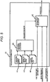
- FIG. 3 illustrates an exemplary processing block of the data integration unit 09.
Landscapes
- Engineering & Computer Science (AREA)
- Physics & Mathematics (AREA)
- General Physics & Mathematics (AREA)
- Theoretical Computer Science (AREA)
- Multimedia (AREA)
- Traffic Control Systems (AREA)
- Mechanical Engineering (AREA)
- Control Of Driving Devices And Active Controlling Of Vehicle (AREA)
Abstract
Description
- The present invention relates to a vehicle periphery information management device that acquires and manages information on the periphery of a vehicle and provides the information externally.
- Recently, for automatic drive control regarded as important, a plurality of information acquisition devices is required to be mounted on a vehicle in order to secure the entire circumference of the vehicle. Information acquired from the information acquisition devices that have been mounted, widely covers, for example, detected information in an external environment recognition sensor, map information, and vehicle-to-vehicle communication information, so that the amount of information handled in vehicle control increases. Therefore, the load on an in-vehicle network and the processing load of the control are predicted to increase, and thus a device capable of effectively managing the information and providing the information, is required.
- As an exemplary system that reduces the load on the in-vehicle network, for example,
PTL 1 discloses that a plurality of in-vehicle networks is provided with respective unification ECUs and the unification ECUs each select and transmit necessary information for the other networks from information that has been received, so that the amount of data is optimized. InPTL 1, the networks include a vehicle motion system managing, for example, brakes, steering, and ACC control, a power train system managing, for example, an engine and a transmission, and an electrical power system managing, for example, a battery and an alternator, so that the information on the vehicle is effectively received and transmitted between the systems. - PTL 1:
JP 2004-136816 A - Object recognition information to be acquired increases in a travel situation, for example, in a case where a vehicle periphery environment is congested. Therefore, as described above, since the plurality of information acquisition devices is mounted for the automatic drive control, the amount of data provided from the information acquisition devices increases in proportion to, for example, object information and road sign information that have been recognized. In
PTL 1, it is not assumed that the amount of information increases in accordance with a travel situation, and the amount of data to be transmitted increases as the number of objects or road signs to be recognized increases. Therefore, there is a problem that the load on a network and the processing load on the information acquisition side, increase. - An object of the present invention is to provide a vehicle periphery information management device capable of inhibiting the load of a network and the processing load on the acquisition side.
- In order to solve the problem, the vehicle periphery information management device according to the present invention includes: for example, a data integration unit configured to integrate vehicle periphery environment information that has been acquired; and a filter unit configured to filter data integrated by the data integration unit. The filter unit performs processing of removing periphery environment information data present in a region at more than a predetermined distance from a vehicle, from the data that has been integrated.
- According to the present invention, the vehicle periphery information management device that inhibits the load of the network and the processing load on the acquisition side, can be provided.
-
- [
FIG. 1] FIG. 1 is an exemplary configuration of an in-vehicle system with a vehicle periphery information management device according to the present invention. - [
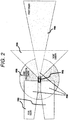
FIG. 2] FIG. 2 is a diagram of an exemplary recognition range in an external environment according to the present invention. - [
FIG. 3] FIG. 3 is a diagram of an exemplary processing block of a data integration unit according to the present invention. - [
FIG. 4] FIG. 4 is a diagram of an exemplary processing block of a filter parameter determination unit according to the present invention. - [
FIG. 5] FIG. 5 is a diagram of an exemplary processing block of a travelable region determination unit according to the present invention. - [
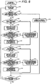
FIG. 6] FIG. 6 is a flowchart of travelable region calculation according to the present invention. - [
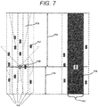
FIG. 7] FIG. 7 is a diagram for describing an exemplary travel region to be searched according to the present invention. - [
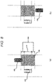
FIG. 8] FIG. 8 is a diagram for describing exemplary adjacent traffic lane movability determination according to the present invention. - [
FIG. 9] FIG. 9 is a diagram for describing atravelable region scene 1 according to the present invention. - [
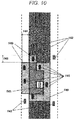
FIG. 10] FIG. 10 is a diagram for describing a travelable regionadjacency information scene 1 according to the present invention. - [
FIG. 11] FIG. 11 is a diagram for describing a travelable region scene 2 according to the present invention. - [
FIG. 12] FIG. 12 is a diagram for describing a travelable region adjacency information scene 2 according to the present invention. - [
FIG. 13] FIG. 13 is a diagram for describing a travelable region adjacency information scene 3 according to the present invention. - [
FIG. 14] FIG. 14 is a table of an exemplary periphery-information-based filter cycle list. - [
FIG. 15] FIG. 15 is a table of an exemplary periphery-information-based data-to-be-filtered list. - [
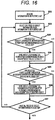
FIG. 16] FIG. 16 is a flowchart of filter parameter calculation according to the present invention. - [
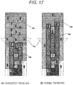
FIG. 17] FIG. 17 is a diagram for describing the comparison between congested traveling and normal traveling according to the present invention. - An embodiment of the present invention will be described below with reference to the drawings.
-
FIG. 1 illustrates the configuration of a vehicle peripheryinformation management device 01, the internal functions thereof, information acquisition devices, and information provision destinations, in a vehicle. The vehicle peripheryinformation management device 01 receives, through aninput communication network 12, information indicating the behavior of the vehicle, acquired from a vehiclebehavior recognition sensor 02, information on, for example, an object/obstruction and a road sign in an external environment, acquired from an externalenvironment recognition sensor 03, information on, for example, a road shape and a road sign, acquired from amap 04, and vehicle position information acquired fromGPS 05, included in the information acquisition devices, so as to perform management in an unificatory manner. The information managed by the vehicle peripheryinformation management device 01, is narrowed down, in data, to minimum information necessary for automaticdrive control ECU 06, anactuation ECU 07, and adisplay ECU 08, included in the information provision destinations, each to perform the corresponding processing, so that the minimum information is transmitted through anoutput communication network 13. - The vehicle
behavior recognition sensor 02 includes, for example, a gyroscope sensor, a wheel speed sensor, a steering angle sensor, and an acceleration sensor, mounted on the vehicle, and a yaw rate, wheel speed, a steering angle, and acceleration, indicating the behavior of the vehicle, can be acquired by the respective sensors. - The external
environment recognition sensor 03 includes sensors, such as a camera and radar, and can acquire the relative position and state of an object, an obstruction, or a road sign on the periphery of the vehicle. - As illustrated in
FIG. 2 , the vehicle F01 is equipped with rear radar F02, an entire circumferential camera F03, a front camera F04, and front radar F05, and includes a detection system capable of detecting information on the entire circumference. - The amount of acquirable information increases as the number of sensors included in the external
environment recognition sensor 03 to be mounted increases, so that a reduction effect in data to be transmitted to the network, improves. However, the external environment recognition sensor is not necessarily mounted over the entire circumference. For example, in the configuration of the single front camera F04, the amount of acquirable data increases as the number of objects to be recognized increases. Thus, a travelable region only ahead is determined so that the amount of data to be transmitted to the network can be reduced. Vehicle-to-vehicle communication and road-to-vehicle communication may be also included in the configuration in addition to the externalenvironment recognition sensor 03. In the vehicle-to-vehicle communication, for example, a yaw rate, a steering angle, speed, acceleration, a brake lamp state, and an indicator state, indicating the behavior of a different vehicle, can be wirelessly acquired. In the road-to-vehicle communication, the position and state of a road sign, a signal, or a different vehicle that has passed by, can be wirelessly acquired through a roadside device provided on a road. - The
map 04 distributes road information in a range of several kilometers on the periphery of the vehicle. Examples of the road information to be distributed, include speed limit information, road information on the curvature of a road, the gradient of the road, the width of the road, the number of traffic lanes, the position of a branch, the position of merging, and the position of a tollgate. - The GPS 05 represents a GPS receiver that receives a signal from a satellite in the sky, and can acquire the position of the vehicle. Besides, for example, the orientation, the speed, the altitude of the vehicle can be acquired as additional information.
- The
input communication network 12 and theoutput communication network 13 each receive and transmit the information through, for example, a controller area network (CAN) being a network typically used in an in-vehicle system, serial communication between CPUs, Ethernet (registered trademark) to be predicted to spread in the future, or wireless communication. - The automatic
drive control ECU 06 has a function in which the steering, the brake, and the accelerator of the vehicle are automatically controlled to cause the vehicle to reach the position of a destination. The automatic drive control may be fully automatic to require no operations of a driver or may be semiautomatic to automatically control a part of the operations. - The
actuation ECU 07 controls the travel stability of the vehicle to be retained, similarly to traction control or an anti-lock braking system. - The
display ECU 08 includes an ECU for displaying information on the periphery of the vehicle, onto, for example, a navigation system or a meter panel. According to the present invention, the three ECUs of the automaticdrive control ECU 06, theactuation ECU 07, and thedisplay ECU 08 have been exemplified for a user of the information in the vehicle peripheryinformation management device 01, but may be varied in accordance with a utilization purpose or the configuration of the vehicle. - The vehicle periphery
information management device 01 includes a data integration unit (hereinafter, also referred to as a data acquisition unit) 09 and a data selection unit 14. The data selection unit 14 includes a filterparameter determination unit 10 and an outputdata filter unit 11. The filterparameter determination unit 10, theoutput data unit 11, and thedata integration unit 09 acquire vehicle behavior information, external environment recognition information, map information, and vehicle position information acquired from the vehiclebehavior recognition sensor 02, the externalenvironment recognition sensor 03, themap 04, and theGPS 05, respectively, through theinput communication network 12. Since acquiring the information from the various information acquisition devices, thedata integration unit 09 performs integration into vehicle information and vehicle periphery information, in consideration of the characteristics of each of the information acquisition devices. Thedata integration unit 09 acts as preprocessing for performing the filterparameter determination unit 10 and the output data filterunit 11, and is a constituent element based on the premise that the consistency of data from the plurality of information acquisition devices operating in asynchronization is ensured and the output data filter unit performs processing of reducing the amount of data. The filterparameter determination unit 10 calculates a parameter regarding how filtering is performed to the vehicle periphery information that has been integrated and how data to be transmitted is reduced. The output data filterunit 11 filters the vehicle periphery information, on the basis of the filter parameter calculated by the filterparameter determination unit 10, so as to transmit the vehicle periphery information including the data to be transmitted, reduced, after the filter, to theoutput communication network 13. -
FIG. 3 illustrates an exemplary processing block of thedata integration unit 09. - The
data integration unit 09 includes a coordinateconversion processing unit 20, asynchronization processing unit 21, an objectgrouping processing unit 22, an objecttracking processing unit 23, and an object traffic laneposition determination unit 24. As inputs to thedata integration unit 09, the respective pieces of information from the vehiclebehavior recognition sensor 02, the externalenvironment recognition sensor 03, themap 04, and theGPS 05, are handled. The coordinateconversion processing unit 20 and thesynchronization processing unit 21 are required to generate the vehicle information and the vehicle periphery information ensuring the consistency of the respective pieces of information input from the plurality of information acquisition devices. The objectgrouping processing unit 22 and the objecttracking processing unit 23 are required to cause information on respective objects acquired from the plurality of information acquisition devices, to be consistent information bearing comparison with the real world. The object traffic laneposition determination unit 24 is required to calculate the position of an object ensuring the consistency in the objects and traffic lane information from the map. - For the inputs to be received by the
data integration unit 09, it is considered that respective coordinate systems handled by the information acquisition devices are different from each other. For example, for the wheel speed sensor being one sensor in the vehiclebehavior recognition sensor 02, a coordinate system to be handled is predicted being a Cartesian coordinate system centering on the position of each of the four wheels. For the millimeter-wave radar for front collision avoidance, being one sensor in the externalenvironment recognition sensor 03, a coordinate system to be handled is predicted being a Cartesian coordinate system centering on the position of the head of the vehicle, the Cartesian coordinate system facing in the travel direction of the vehicle. It is predicted that a geodetic coordinate system is used for the coordinate system handled by themap 04 and a position on the earth is indicated in latitude and longitude. In order to absorb the difference between the coordinate systems, the coordinateconversion processing 20 performs conversion into one coordinate system being representative, and the information that has been converted is handled in the subsequent processing. For example, a coordinate system including a Cartesian coordinate system having the center of the vehicle as a criterion, may be provided as a representative. The conversion into the one coordinate system being representative, requires no coordinate conversion processing to be performed in accordance with the characteristics of the information acquisition devices every time the information in the externalenvironment recognition sensor 03 is linked with the information in themap 04 in the subsequent processing. - Next, the
synchronization processing unit 21 corrects and synchronizes the acquisition time lags between respective pieces of data acquired from the information acquisition devices. In the in-vehicle system, each of the information acquisition devices operates asynchronously and has a difference, for example, in the transmission cycle of data. Therefore, for example, when the position information on an object acquired from each of the information acquisition devices, is used remaining intact, the relative position gaps occur between the respective objects detected by the information acquisition devices, and thus a difference occurs in the relative positional relationship between the information in the vehicle periphery information management device and the object in the real world. As a result, the risk of collision increases to cause danger in automatic driving that determines and controls the positional relationship between a plurality of vehicles. - In a case where the respective objects detected by the information acquisition devices are the same in the real world, the object
grouping processing unit 22 determines the objects as identical. When the number of sensors in the externalenvironment recognition sensor 03 mounted on the vehicle increases, the individual sensors in the externalenvironment recognition sensor 03 may detect the same region. For example, the rear radar F02, the entire circumferential camera F03, the front camera F04, and the front radar F05 detect respective objects in overlapped regions F06 in an exemplary external environment recognition range ofFIG. 2 . For this configuration, if the vehicle periphery information management device transmits the objects as different to the automaticdrive control ECU 06 regardless of the objects identical in the real world, predicting a move and performing control are originally at least required to one object, but the moves of the plurality of objects must be predicted so that unnecessary processing occurs. Therefore, if respective objects detected by different sensors in the external environment recognition sensor are identical, there is a need to perform grouping to the objects as identical and to transmit the objects as identical to the control. - The object
tracking processing unit 23 acts as processing of continuing to recognize an object as the same even when the object passes through the respective recognition range boundaries of the information acquisition devices. With a description having the exemplary external environment recognition range ofFIG. 2 , in a situation in which a different vehicle overtakes from the right rear of the vehicle F01, the different vehicle is first detected at the right rear of the rear radar F02, and then the recognition is switched from the right rear of the rear radar F02 to the right side of the entire circumferential camera F03 as the different vehicle moves to the right side of the vehicle. In this case, in a case where viewed from the rear radar F02 that has performed the first detection, when the different vehicle deviates from the recognition range of the right rear of the rear radar F02, information on the different vehicle in the rear radar F02 is interrupted. Instead, since the different vehicle moves to the right side of the entire circumferential camera F03, the entire circumferential camera F03 outputs the interrupted information on the different vehicle in the rear radar F02. In this manner, with even information on an object interrupted when viewed from each of the information acquisition devices, theobject tracking processing 23 handles the objects as identical. Without the processing, when the vehicle periphery information management device makes a switch to the entire circumferential camera F03 and performs recognition as a different object despite the objects identical in the real world, the object to which attention has been paid, disappears and it looks as if a new object appears, as data. Therefore, the control cannot continue to the objects identical, on the control side, and thus the precision of object behavior prediction degrades and there is a risk that the reliability of the control degrades. According to the present embodiment, when the continuity of data of an object/obstruction is lost, the determination precision of a travelable region calculated from the positional relationship with the object/obstruction, degrades and the data reduction effect may decrease. Therefore, even when detection is performed by different sensors in the external environment recognition sensor, the objects may be regarded as identical in the tracking processing so as to be transmitted to the control. - The object traffic lane
position determination unit 24 determines in which traffic lane on the road the object/obstruction detected by each of the information acquisition devices is present. According to the present embodiment, processing of calculating a travelable region per traffic lane, is assumed in the following descriptions, and thus there is a need to calculate in which traffic lane the object/obstruction detected by each of the information acquisition devices is present. - The processing is performed to finally output the vehicle information and the vehicle periphery information. The vehicle information here includes, for example, the vehicle position information, the speed, yaw rate, steering angle, acceleration, indicator information, and brake lamp information of the vehicle. The vehicle periphery information includes, for example, the relative position, relative speed, and travel traffic lane position of another vehicle, a pedestrian, or a two-wheeled vehicle present on the periphery of the vehicle. Road information, sign information, and signal information present on the periphery of the vehicle are also included.
-
FIG. 4 illustrates an exemplary processing block of the filterparameter determination unit 10. - The filter
parameter determination unit 10 includes a travelableregion determination unit 30, a travelable region adjacent peripheryinformation determination unit 31, a peripheryinformation determination unit 32 not for travelable region adjacent periphery information, and a filter parameter integration unit 33. First, the travelableregion determination unit 30 calculates a travelable region with, as an input, the vehicle periphery information from thedata integration unit 09. The travelableregion determination unit 30 has a function of calculating a region in which the vehicle can travel, on the basis of the vehicle periphery information, and determines whether the vehicle can move to the region. According to the present embodiment, for the determination of the movability, the movability is basically determined in a case where an event in which a different object/obstruction obstructs the travel of the vehicle, does not happen in a region to which the vehicle moves. With the travelable region output from the travelableregion determination unit 30 and the vehicle periphery information from thedata integration unit 09, the travelable region adjacent peripheryinformation determination unit 31 calculates a travelable region adjacency information list. The travelable region adjacency information list includes information listing, for example, objects/obstructions that can immediately enter the travelable region. That is, the information indicates immediately approachability to the vehicle, and has high priority as information in consideration of a safety aspect. With the travelable region adjacency information list output from the travelable region adjacent peripheryinformation determination unit 31 and the vehicle periphery information from thedata integration unit 09, the peripheryinformation determination unit 32 not for the travelable region adjacent periphery information calculates an information-to-be-filtered list. The information-to-be-filtered list includes information listing, for example, objects/obstructions and signs that have not been registered in the travelable region adjacency information list but have been recognized by the external environment recognition sensor and the map. That is, the information indicates immediately inapproachability to the vehicle, and has low priority as information in consideration of the safety aspect. With the information-to-be-filtered list output from the peripheryinformation determination unit 32 not for the travelable region adjacent periphery information, a periphery-information-basedfilter cycle list 34, and a periphery-information-based data-to-be-filtered list 35, the filter parameter integration unit integrates parameters so as to make an output to the output data filter unit. A filter parameter that has been calculated, is used for the filter processing in the output data filterunit 11. The periphery-information-basedfilter cycle list 34 and the periphery-information-based data-to-be-filtered list 35 may be previously statically determined by a system designer or may be externally received and set as dynamical parameters. For example, in a case where the external reception is performed, a method of collecting respective parameters from the automaticdrive control ECU 06, theactuation ECU 07, and thedisplay ECU 08 ofFIG. 1 , is considered. -
FIG. 5 illustrates an exemplary processing block of the travelableregion determination unit 30. - The travelable
region determination unit 30 includes a travel-region-to-be-searched calculation unit 40 and a travelableregion calculation unit 41. The travel-region-to-be-searched calculation unit 40 receives a frontmaximum detection distance 42, a rearmaximum detection distance 43, and an accessibletraffic lane count 44 that have been previously set, and then outputs a travel region to be searched to the travelableregion calculation unit 41. The travel region to be searched includes a region to be searched of a periphery object/obstruction in calculating the travelable region below, and, in this case, a region detected by the external environment recognition sensor is exemplarily to be searched. Therefore, the frontmaximum detection distance 42 and the rearmaximum detection distance 43 are used as inputs. The accessibletraffic lane count 44 is set to a fixed value since the number of traffic lanes to which the vehicle can immediately move, is not so large. The travelableregion calculation unit 41 receives the travel region to be searched calculated by the travel-region-to-be-searched calculation unit 40, vehicle periphery traffic lane information, the distance from the vehicle to the periphery object/obstruction, and the traffic lane position of the periphery object/obstruction, so as to output the travelable region.FIG. 7 illustrates a diagram for describing the travel region to be searched.FIG. 7 illustrates the vehicle F10, traffic lanes F11, an object/obstruction F12 (a vehicle not being the vehicle F10) detected by the external environment recognition sensor, on the periphery of the vehicle, an external environment recognition sensor detection region F13, and the travel region to be searched F14. The travel region to be searched F14 is calculated with the front maximum detection distance F15 and the rear maximum detection distance F16 detected in the external environment recognition sensor detection region F13, and the accessible traffic lane count F17 that has been previously set. Here, the accessible traffic lane count F17 exemplarily expresses three traffic lanes of the left traffic lane and the right traffic lane to which the vehicle can immediately move, and the travel traffic lane of the vehicle. With the vehicle F10 centered, the three traffic lanes of the accessible traffic lane count F17 up to the front maximum detection distance F15 are to be searched in the front, and the three traffic lanes of the accessible traffic lane count F17 up to the rear maximum detection distance F16 are to be searched in the rear. In a case where the vehicle is in the right end traffic lane, two traffic lanes of the travel traffic lane of the vehicle and the left traffic lane of the vehicle are required at least to be searched. -
FIG. 6 illustrates an exemplary flowchart of the travelableregion calculation unit 41. - First, the travel-region-to-
be-searched calculation unit 40 illustrated inFIG. 5 calculates the travel region to be searched, at S01. - Next, one traffic lane is selected from the traffic lanes in the travel region to be searched, at S02. In the example of
FIG. 7 , the three traffic lanes are provided at a maximum, and thus one traffic lane is selected therefrom and the subsequent set of processing S03 to S15 is performed. The set of processing S03 to S15 is repeated until all the three traffic lanes are processed. The set of processing S03 to S15 includes two pieces of processing, and a set of processing S05 to S09 acts as processing of calculating the travelable region ahead of the vehicle and a set of processing S10 to 14 acts as processing of calculating the travelable region behind the vehicle. - Next, in a case where the traffic lane that has been selected is an adjacent traffic lane to the vehicle (the left traffic lane or the right traffic lane), it is determined whether the vehicle can move to the adjacent traffic lane, at S03. The determination of whether the vehicle can move to the adjacent traffic lane, will be described with exemplary adjacent traffic lane movability determination of
FIG. 8 . For the movability of the vehicle F20 ofFIG. 8(a) to the right traffic lane, it is determined whether a different vehicle F21 belongs to a movability region F25 even in a small degree, and non-movability is determined in a case where belonging to the movability region F25 even in the small degree. ForFIG. 8(a) , the different vehicle F21 belongs to the movability region F25 so that non-movability is determined. ForFIG. 8(b) , a different vehicle F22 does not belong to the movability region F25 so that movability is determined. The longitudinal width of the movability region F25 is expressed as a region including a front/rear margin distance F24 added to the entire vehicle length F23 of the vehicle F20 illustrated inFIG. 8(a) . The width of the traffic lane is used for the lateral width of the movability region F25. Even when a region in size the same as the entire vehicle length F23 is vacant, a move cannot be made in practice and there is a need to keep a degree of inter-vehicular distance. Thus, the front and rear margin distance F24 is defined in the adjacency movability determination. If the vehicle cannot move to the adjacent traffic lane, it is determined that no travelable region is in the traffic lane that has been selected, at S04. Exemplarily with atravelable region scene 1 ofFIG. 9 , since a different vehicle is present in the right traffic lane of the vehicle, a traffic lane F30 in the travel region to be searched F14 is excluded from the travelable region, at S04. In this manner, the reason why the traffic lane to which the vehicle cannot immediately move is excluded from the travelable region, is that a region to which no move can be made is to be included in the travelable region if the traffic lane to which the vehicle cannot immediately move is included in the travelable region, and the reduction effect of the amount of data to be transmitted decreases. - Next, in a case where the vehicle can move to the adjacent traffic lane, it is determined whether a different object/obstruction is present ahead in the traffic lane that has been selected, at S05. In a case where no object/obstruction is present, a distance to a different object/obstruction present in the adjacent traffic lane to the traffic lane that has been selected, is included in the travelable region, at S06. Exemplarily with a travelable region scene 2 of
FIG. 11 , since no vehicle is present ahead in the right traffic lane of the vehicle, the travelable region includes the front maximum detection distance of the right traffic lane, with simple consideration. Note that, with this arrangement, the region to which no immediate move can be made, is also included in the travelable region and the reduction effect of the amount of data to be transmitted decreases. Thus, according to the present embodiment, in a case where no different object/obstruction is present ahead in the right traffic lane that has been selected, the travelable region F51 is set with a distance from a different object/obstruction F50 present in the left adjacent traffic lane (a different object/obstruction ahead of the vehicle) to the vehicle. In a case where a different object/obstruction is present ahead, a distance to the nearest object/obstruction ahead in the traffic lane that has been selected, is acquired at S07. - Next, it is determined whether the difference between the distance acquired at S07 and the distance to the different object/obstruction nearest to the vehicle, present in the adjacent traffic lane, is a certain value or less, at S08. In a case where the difference is larger than the certain value, the distance to the different object/obstruction present in the adjacent traffic lane to the traffic lane selected at S06, is included in the travelable region. As exemplarily illustrated in a travelable region adjacency information scene 3 of
FIG. 13 , in a case where the difference F73 in distance between a different object/obstruction F70 present ahead in the right traffic lane of the vehicle and a different object/obstruction F71 present ahead of the vehicle, is large, the travelable region in the right traffic lane of the vehicle practically includes a travelable region to which no immediate move can be made. Thus, in this case, the travelable region F72 is set with the distance to the different object/obstruction F71 ahead of the vehicle. In a case where the distance F73 is the certain value or less, the distance from the vehicle to the different object/obstruction ahead, is included in the travelable region at S09. Exemplarily with the left traffic lane of the vehicle in thetravelable region scene 1 ofFIG. 9 , since the distance F34 between the object/obstruction ahead of the vehicle and an object/obstruction ahead in the left traffic lane, is short, a distance to the nearest object/obstruction ahead in the left traffic lane, is set to the travelable region in the left traffic lane F31. Exemplarily with the travel traffic lane of the vehicle, a distance to the nearest object/obstruction ahead, is set to the travelable region in the travel traffic lane F32. - A set of processing from S05 to S09 above is performed to the front direction of the vehicle, whereas a set of processing from S10 to S14 is performed to the rear direction of the vehicle and it is determined whether an object/obstruction is present behind the vehicle in the traffic lane that has been selected, at S10. In a case where no object/obstruction is present, a distance to an object/obstruction present in the adjacent traffic lane to the traffic lane that has been selected, is included in the travelable region at S11. In a case where an object/obstruction is present, a distance to the nearest different object/obstruction behind the vehicle in the traffic lane that has been selected, is acquired at S12. Next, it is determined whether the difference between the distance that has been acquired and the distance to the nearest different object/obstruction to the vehicle, present in the adjacent traffic lane, is a certain value or less, at S13. In a case where the difference is larger than the certain value, the travelable region is set at S11. In a case where the difference is the certain value or less, the distance to the different object/obstruction behind the vehicle, is included in the travelable region at S14.
- Next, it is determined whether the travelable region for each of the traffic lanes has been calculated with a set of processing S02 to S14 above, at S15, and if the calculation has not been completed, the processing is repeated from S02. If the calculation has been completed, the processing of calculating the travelable region finishes.
- As a result of the processing in the flowchart of the travelable region calculation illustrated in
FIG. 6 , the travelable region F33 is calculated exemplarily with thetravelable region scene 1 ofFIG. 9 . The travelable region F52 is calculated exemplarily with the travelable region scene 2 ofFIG. 11 . - The travelable region adjacent periphery
information determination unit 31 ofFIG. 4 , will be described. - When the
travelable region scene 1 ofFIG. 9 is applied to the travelableregion determination unit 30 ofFIG. 4 , the travelable region F33 is acquired. The travelable region adjacent periphery information indicates a region adjacent to the travelable region F33 ofFIG. 9 , and indicates a region F40 in the travelable region adjacencyinformation scene 1 ofFIG. 10 . The minimum longitudinal width F43 of the travelable region adjacent region, may use the entire length of a different object/obstruction F41 or may be varied in accordance with the vehicle speed of the different object/obstruction F41. The minimum lateral width F44 thereof may use the entire width of the different object/obstruction F41 or may use the width of a traffic lane acquired from the map or a camera. Different objects/obstructions F41 positioned on the travelable region adjacent region F40, are defined as the travelable region adjacent periphery information. The travelable region adjacent peripheryinformation determination unit 31 outputs the travelable region adjacency information list listing the plurality of different objects/obstructions. The travelable region adjacent region in the travelable region adjacency information scene 2 ofFIG. 12 is indicated with F60, to the travelable region F52 illustrated in the travelable region scene 2 ofFIG. 11 . Similarly to the example ofFIG. 10 , different objects/obstructions F61 positioned on the region F60, are included in the travelable region adjacent periphery information, and the plurality of different objects/obstructions are listed so as to be output to the peripheryinformation determination unit 32 not for the travelable region adjacent periphery information. As described above, since the different objects/obstructions allocated to the travelable region adjacent periphery information, are adjacent to the travelable region of the vehicle, the different objects/obstructions have high possibility of immediately moving to the travelable region of the vehicle. The travelable region adjacent periphery information has high priority as information to be provided, and thus providing detailed information on the position and behavior of each of the objects/obstructions, to the user, is required. - The periphery
information determination unit 32 not for the travelable region adjacent periphery information ofFIG. 4 , will be described. - The periphery
information determination unit 32 not for the travelable region adjacent periphery information, outputs, as the information-to-be-filtered list, different objects/obstructions F42 detected by the external environment recognition sensor, to the filter parameter integration unit 33, except the different objects/obstructions F41 included in the travelable region adjacency information list, illustrated inFIG. 10 . Similarly, inFIG. 12 , as the information-to-be-filtered list, different objects/obstructions F62 detected by the external environment recognition sensor, are output to the filter parameter integration unit 33, except the different objects/obstructions F61 included in the travelable region adjacency information list. The information-to-be-filtered list that has been selected here, indicates the objects/obstructions that do not immediately move to the travelable region of the vehicle, having low priority, differently from the objects/obstructions having high priority, adjacent to the travelable region. Therefore, it can be predicted that no large influence is exerted on the objects/obstructions registered in the information-to-be-filtered list even when data to be provided to the user is reduced. - A method of calculating a parameter for filtering the information-to-be-filtered list by the filter parameter integration unit 33 of
FIG. 4 , will be described. - With the information-to-be-filtered list from the periphery information determination unit not for the travelable region adjacent periphery information, the filter parameter integration unit 33 performs processing of selecting parameters to be filtered from the periphery-information-based
filter cycle list 34 and the periphery-information-based data-to-be-filtered list 35. The periphery-information-basedfilter cycle list 34 includes a list for reducing the amount of data by temporal data decimation. The periphery-information-based data-to-be-filtered list 35 includes a list for reducing the amount of data by quantitative data decimation. - First, an exemplary periphery-information-based filter cycle list will be described with
FIG. 14 . In the periphery-information-based filter cycle list ofFIG. 14 , vehicle periphery information object classification includes a periphery three-dimensional object and periphery road surface information. The periphery three-dimensional object includes, for example, an object, a signal, a sign, and a road end. Furthermore, the object includes information on, for example, an object ID, a relative position, a relative speed, a width, and a height. The signal includes information on, for example, a signal ID, a classification, a relative position, and a state. In addition, the sign and the road end each include detailed information. The periphery road surface information includes information on, for example, a lane marker and additional paint. Furthermore, the lane marker includes information on, for example, a lane ID, a lane classification, a relative position, and a yaw angle. The additional paint includes, for example, a paint ID, a relative position, and a classification. Respective cycles in which the descriptions are transmitted, are defined in the present list. Here, a transmission cycle in a default and a cycle in filtering, are defined. Basically, the transmission cycle in the default, is set to a value faster than that of the cycle in the filtering, and the transmission cycle in the default is allocated to the information in the travelable region adjacent periphery information list. In contrast, the cycle in the filtering is allocated to the information-to-be-filtered list being an object of which data to be transmitted is desirably reduced, so that the amount of data to be transmitted within a certain period is inhibited. For example, taking the relative position of the object in the periphery three-dimensional object as an example, a default cycle of 60 ms is applied to each of the objects/obstructions F41 ofFIG. 10 . A filter cycle of 100 ms is applied to each of the objects/obstructions F42. With this arrangement, information can be provided to the user with the amount of data within the certain period, inhibited for the objects/obstructions F42 having low priority in comparison to the objects/obstructions F41 having high priority. - Next, an exemplary periphery-information-based data-to-be-filtered list, will be described with
FIG. 15 . The periphery-information-based data-to-be-filtered list ofFIG. 15 also includes vehicle periphery information object classification similar to that of the periphery-information-based filter cycle list ofFIG. 14 . Here, descriptions to be transmitted in default and descriptions to be transmitted after filtering, are defined. Basically, the descriptions to be transmitted in the default are set larger in quantity than the descriptions to be transmitted after the filtering, and the descriptions to be transmitted in the default are allocated to the information in the travelable region adjacent periphery information list. In contrast, the descriptions to be transmitted after the filtering are allocated to the information-to-be-filtered list being the object of which the data to be transmitted is desirably reduced, so that the descriptions to be transmitted are decimated and the amount of data is inhibited. For example, exemplarily with the width of the object in the periphery three-dimensional object, width data for each of the objects/obstructions F41 ofFIG. 10 , is transmitted in accordance with the descriptions to be transmitted in the default. Width data for each of the objects/obstructions F42 is not transmitted in accordance with the descriptions to be transmitted after the filtering. With this arrangement, information can be provided to the user with the amount of data inhibited for the objects/obstructions F42 having the low priority in comparison to the objects/obstructions F41 having the high priority. The method of reducing the amount of data to be transmitted, with the descriptions themselves decimated, has been described with the exemplary periphery-information-based data-to-be-filtered list ofFIG. 15 , but a method of compressing and transmitting data may be used. - As illustrated in the travelable region adjacency
information scene 1 ofFIG. 10 , a region F45 being the travelable region on the periphery of the vehicle, the region F40 being a region adjacent to the travelable region, and the other region may be prioritized, and then the filter parameter may be calculated with the priority determined for each region. For example, the region F45 being the travelable region on the periphery of the vehicle is set to high priority, the region F40 being the region adjacent to the travelable region is set to medium priority, and the other region is set to low priority. In this case, the filter parameter to the respective different objects/obstructions belonging to the regions, may be varied in accordance with priority. Exemplarily with the periphery-information-based filter cycle list ofFIG. 14 , two cycles of the default cycle and the filter cycle are defined inFIG. 14 . In a case where priority is used, a filter cycle having high priority, a filter cycle having medium priority, and a filter cycle having low priority are individually defined, and then a transmission cycle having a faster value is set to each cycle in order of priority. Similarly, information to be reduced is individually defined based on priority for the periphery-information-based data-to-be-filtered list ofFIG. 15 . - Next, an exemplary flowchart of filter parameter calculation of calculating the filter parameter output from the filter parameter integration unit 33, will be described with
FIG. 16 . First, the information-to-be-filtered list is acquired at S21. Next, one piece of object information is selected from the information-to-be-filtered list that has been acquired, at S22. It is checked whether the object classification in the selected information has been registered in the periphery-information-based filter cycle list ofFIG. 14 , at S23. In the example ofFIG. 14 , examples of the object classification include the periphery three-dimensional object and the periphery road surface information. In a case where no registration has been made, processing of updating the filter parameter of the selected object information, is skipped. In a case where the registration has been made, a filter cycle corresponding to each description of the selected object, is saved in the filter parameter at S24. Here, each description indicates the object ID or relative position of the object, the lane ID or lane classification of the lane marker inFIG. 14 . Next, it is checked whether the selected object classification has been registered in the periphery-information-based data-to-be-filtered list ofFIG. 15 , at S25. In a case where no registration has been made, the processing of updating the filter parameter of the selected object information, is skipped. In a case where the registration has been made, the description to be transmitted after the filtering corresponding to each description of the selected object, is saved in the filter parameter at S26. Next, it is determined whether all pieces of object information have been selected, at S27. In a case where the selection has not been completed, the processing is repeatedly performed from S22 to S26. In a case where the selection has been completed, the processing of calculating the filter parameter is completed. - As illustrated in
FIG. 4 , the filter parameter calculated in the flowchart ofFIG. 16 is output to the output data filterunit 11. The output data filterunit 11 determines whether the object for each piece of vehicle periphery information output from thedata integration unit 09, has been registered in the filter parameter. The data is reduced with the filter parameter for the object that has been registered, and the data is transmitted with the default set for the object that has not been registered. - The effect of the present invention will be described with the comparison between congested traveling and normal traveling of
FIG. 17. FIG. 17 (a) illustrates the congested traveling andFIG. 17(b) illustrates the normal traveling. The traveling is performed keeping a degree of inter-vehicular distance to a vehicle present ahead of the vehicle in the normal traveling ofFIG. 17 (b) in comparison to the congested traveling. Thus, when the flowchart illustrated inFIG. 6 is used, the travelable region F83 in the normal traveling, expands as the inter-vehicular distance lengthens. Therefore, the region of the travelable region F83 in the normal traveling, occupies a large part of a recognition region F82 of the external environment recognition sensor so that a region F84 to be filtered ahead of the vehicle, narrows and objects/obstructions to be filtered are limited. Note that, the inter-vehicular distance between objects/obstructions is originally wide, and thus the amount of data to be provided is not enormous. In contrast, in the congested traveling ofFIG. 17 (a) , a plurality of vehicles ahead of the vehicle, travels at low speed keeping narrow inter-vehicular distances, and thus the range of the travelable region F80 narrows. In comparison to the normal traveling, the region of the travelable region F80 is merely a part of the recognition region F82 of the external environment recognition sensor, and thus a region F81 to be filtered ahead of the vehicle more expands than in the normal traveling. As a result, the number of vehicles detected by the external environment recognition sensor may increase, and thus the amount of information to be provided increases in the conventional processing. According to the present invention, the filter processing is performed to the objects/obstructions included in the region F81 to be filtered so that the amount of data to be provided can be reduced. Therefore, even in a state where the external environment recognition sensor can detect a large number of vehicles as in the congested traveling, the load on the network due to the information provision, can be smoothed. The processing load on the information acquisition side can be reduced. -
- 01
- vehicle periphery information management device
- 02
- vehicle behavior recognition sensor
- 03
- external environment recognition sensor
- 04
- map
- 05
- GPS
- 06
- automatic drive control ECU
- 07
- actuation ECU
- 08
- display ECU
- 09
- data integration unit (data acquisition unit)
- 10
- filter parameter determination unit
- 11
- output data filter unit
- 12
- input communication network
- 13
- output communication network
- 14
- data selection unit
Claims (10)
- A vehicle periphery information management device comprising:a data acquisition unit configured to acquire a plurality of pieces of external environment information data around a vehicle; anda data selection unit configured to select a part of the plurality of pieces of external environment information data acquired by the data acquisition unit so as to make an output outside, based on a predetermined position of the vehicle.
- The vehicle periphery information management device according to claim 1, wherein
the data selection unit deletes periphery environment information data present in a region at more than a predetermined distance from the vehicle so as to make the output. - The vehicle periphery information management device according to claim 2, wherein
the region exceeding the predetermined distance includes a first region travelable to the vehicle or a second region adjacent to the first region. - The vehicle periphery information management device according to claim 3, wherein,
in a case where a region not adjacent to the first region is defined as a third region,
the data selection unit assigns priority to the periphery environment information data for each of the regions, so as to vary a data description and a data amount to be output based on the priority that has been assigned. - The vehicle periphery information management device according to claim 2, wherein
the data selection unit varies the data to be output per function to be used. - The vehicle periphery information management device according to claim 5, wherein
information in each of the functions to be used, is transmitted from an external control device. - The vehicle periphery information management device according to any of claims 1 to 5, wherein
the data selection unit decimates the part of the external environment information data or the entire data collected by the data acquisition unit, so as to make the output. - The vehicle periphery information management device according to any of claims 1 to 5, wherein
the data selection unit deletes the part of the external environment information data or the entire data collected by the data acquisition unit, so as to make the output. - The vehicle periphery information management device according to any of claims 1 to 5, wherein
the data selection unit compresses the part of the external environment information data or the entire data collected by the data acquisition unit, so as to make the output. - The vehicle periphery information management device according to any of claims 1 to 5, wherein
the external environment information data includes at least obstruction information.
Applications Claiming Priority (2)
| Application Number | Priority Date | Filing Date | Title |
|---|---|---|---|
| JP2015151449 | 2015-07-31 | ||
| PCT/JP2016/071198 WO2017022475A1 (en) | 2015-07-31 | 2016-07-20 | Vehicle periphery information management device |
Publications (3)
| Publication Number | Publication Date |
|---|---|
| EP3330946A1 true EP3330946A1 (en) | 2018-06-06 |
| EP3330946A4 EP3330946A4 (en) | 2019-07-03 |
| EP3330946B1 EP3330946B1 (en) | 2026-04-01 |
Family
ID=57942863
Family Applications (1)
| Application Number | Title | Priority Date | Filing Date |
|---|---|---|---|
| EP16832754.2A Active EP3330946B1 (en) | 2015-07-31 | 2016-07-20 | Vehicle periphery information management device |
Country Status (5)
| Country | Link |
|---|---|
| US (2) | US10493907B2 (en) |
| EP (1) | EP3330946B1 (en) |
| JP (2) | JP6567056B2 (en) |
| CN (1) | CN108352116B (en) |
| WO (1) | WO2017022475A1 (en) |
Cited By (2)
| Publication number | Priority date | Publication date | Assignee | Title |
|---|---|---|---|---|
| WO2020126447A1 (en) * | 2018-12-21 | 2020-06-25 | Volkswagen Aktiengesellschaft | Method and system for providing environmental data |
| WO2023030858A1 (en) * | 2021-08-31 | 2023-03-09 | Volkswagen Aktiengesellschaft | Method and assistance device for supporting vehicle functions in a parking lot, and motor vehicle |
Families Citing this family (19)
| Publication number | Priority date | Publication date | Assignee | Title |
|---|---|---|---|---|
| JP6332384B2 (en) * | 2016-09-29 | 2018-05-30 | マツダ株式会社 | Vehicle target detection system |
| US10663974B2 (en) * | 2016-11-23 | 2020-05-26 | Electronics And Telecommunications Research Institute | Object recognition device, autonomous driving system including the same, and object recognition method using the object recognition device |
| EP3360747A1 (en) * | 2017-02-13 | 2018-08-15 | Autoliv Development AB | Improvements in or relating to driver assistance systems |
| JP6661695B2 (en) * | 2018-05-09 | 2020-03-11 | 三菱電機株式会社 | Moving object detection device, vehicle control system, moving object detection method, and vehicle control method |
| WO2020132938A1 (en) * | 2018-12-26 | 2020-07-02 | Baidu.Com Times Technology (Beijing) Co., Ltd. | Methods for obstacle filtering for non-nudge planning system in autonomous driving vehicle |
| CN113345269B (en) * | 2018-12-28 | 2022-11-08 | 北京百度网讯科技有限公司 | Vehicle danger early warning method, device and equipment based on V2X vehicle networking cooperation |
| US11003195B2 (en) * | 2019-02-28 | 2021-05-11 | GM Global Technology Operations LLC | Method to prioritize the process of receiving for cooperative sensor sharing objects |
| US10741070B1 (en) * | 2019-03-04 | 2020-08-11 | GM Global Technology Operations LLC | Method to prioritize transmission of sensed objects for cooperative sensor sharing |
| US11780474B2 (en) * | 2019-06-13 | 2023-10-10 | Nissan Motor Co., Ltd. | Vehicle travel control method and vehicle travel control device |
| JP7363118B2 (en) * | 2019-06-14 | 2023-10-18 | マツダ株式会社 | External environment recognition device |
| WO2020262718A1 (en) * | 2019-06-25 | 2020-12-30 | 엘지전자 주식회사 | Method for transmitting sensing information for remote driving in automated vehicle & highway systems, and apparatus therefor |
| US12166960B2 (en) * | 2019-07-10 | 2024-12-10 | Hitachi Astemo, Ltd. | Sensing performance evaluation and diagnosis system and sensing performance evaluation and diagnosis method for external-environment recognition sensor |
| DE102019216916A1 (en) | 2019-11-04 | 2021-05-06 | Robert Bosch Gmbh | Method for transmitting a message in a communication network for communication between a road user and at least one other road user |
| JP7392506B2 (en) * | 2020-02-13 | 2023-12-06 | 株式会社アイシン | Image transmission system, image processing system and image transmission program |
| DE102020112036A1 (en) * | 2020-05-05 | 2021-11-11 | Valeo Schalter Und Sensoren Gmbh | DRIVER ASSISTANCE FOR A MOTOR VEHICLE |
| CN113705272B (en) * | 2020-05-20 | 2026-05-29 | 引望智能技术有限公司 | Method, device, equipment and storage medium for detecting drivable area |
| JP7574595B2 (en) * | 2020-09-30 | 2024-10-29 | 株式会社アドヴィックス | Stop detection device |
| JP7546453B2 (en) * | 2020-11-10 | 2024-09-06 | 日立Astemo株式会社 | Map generation and self-location estimation device |
| JP7363831B2 (en) | 2021-02-10 | 2023-10-18 | 株式会社デンソー | Information collection control device, information collection control method, information collection control program |
Family Cites Families (34)
| Publication number | Priority date | Publication date | Assignee | Title |
|---|---|---|---|---|
| US7202776B2 (en) * | 1997-10-22 | 2007-04-10 | Intelligent Technologies International, Inc. | Method and system for detecting objects external to a vehicle |
| JP2880449B2 (en) * | 1996-03-19 | 1999-04-12 | 三菱電機株式会社 | Moving object monitoring method |
| US7899616B2 (en) * | 1997-10-22 | 2011-03-01 | Intelligent Technologies International, Inc. | Method for obtaining information about objects outside of a vehicle |
| JP3676616B2 (en) | 1999-04-28 | 2005-07-27 | 本田技研工業株式会社 | Obstacle detection device |
| JP2001052297A (en) * | 1999-08-06 | 2001-02-23 | Fujitsu Ltd | Safe driving support device, its method and recording medium |
| JP2003217099A (en) | 2002-01-23 | 2003-07-31 | Mitsubishi Electric Corp | In-vehicle peripheral monitoring device |
| JP4134672B2 (en) | 2002-10-18 | 2008-08-20 | 株式会社デンソー | Vehicle control system |
| JP4548181B2 (en) * | 2005-03-31 | 2010-09-22 | 日産自動車株式会社 | Obstacle detection device |
| JP4692831B2 (en) * | 2006-03-28 | 2011-06-01 | アイシン・エィ・ダブリュ株式会社 | Peripheral situation recognition device and method |
| JP4062353B1 (en) * | 2006-11-10 | 2008-03-19 | トヨタ自動車株式会社 | Obstacle course prediction method, apparatus, and program |
| JP5012396B2 (en) | 2007-10-16 | 2012-08-29 | 日産自動車株式会社 | White line detection device, parking and stopping support device, and white line detection method |
| JP2009187351A (en) * | 2008-02-07 | 2009-08-20 | Fujitsu Ten Ltd | Obstacle detecting device and obstacle detecting method |
| DE102008011228B4 (en) * | 2008-02-26 | 2026-01-22 | Robert Bosch Gmbh | Method for assisting a user of a vehicle, control unit for a driver assistance system of a vehicle and vehicle with such a control unit |
| US8605947B2 (en) * | 2008-04-24 | 2013-12-10 | GM Global Technology Operations LLC | Method for detecting a clear path of travel for a vehicle enhanced by object detection |
| JP2010076460A (en) * | 2008-09-23 | 2010-04-08 | Denso Corp | Control device for blinker |
| US8352112B2 (en) * | 2009-04-06 | 2013-01-08 | GM Global Technology Operations LLC | Autonomous vehicle management |
| CN101585361A (en) * | 2009-05-25 | 2009-11-25 | 郭文艺 | Anti-collision and lane-departure-prevention control device for automobile |
| JP4883248B2 (en) * | 2009-06-02 | 2012-02-22 | トヨタ自動車株式会社 | Vehicle periphery monitoring device |
| WO2010140239A1 (en) * | 2009-06-04 | 2010-12-09 | トヨタ自動車株式会社 | Vehicle surrounding monitor device and method for monitoring surroundings used for vehicle |
| CN102763146B (en) * | 2010-02-22 | 2015-02-11 | 丰田自动车株式会社 | Risk degree calculation device |
| JP2011227582A (en) | 2010-04-15 | 2011-11-10 | Toyota Motor Corp | Vehicle collision prediction apparatus |
| JP5197679B2 (en) * | 2010-06-09 | 2013-05-15 | 株式会社豊田中央研究所 | Object detection apparatus and program |
| JP5206752B2 (en) | 2010-08-30 | 2013-06-12 | 株式会社デンソー | Driving environment recognition device |
| JP5338801B2 (en) * | 2010-12-23 | 2013-11-13 | 株式会社デンソー | In-vehicle obstacle information notification device |
| US9146898B2 (en) * | 2011-10-27 | 2015-09-29 | Magna Electronics Inc. | Driver assist system with algorithm switching |
| EP2747056B1 (en) * | 2011-12-27 | 2017-12-06 | Honda Motor Co., Ltd. | Driving assistance system |
| US9412273B2 (en) * | 2012-03-14 | 2016-08-09 | Autoconnect Holdings Llc | Radar sensing and emergency response vehicle detection |
| JP6015329B2 (en) * | 2012-10-11 | 2016-10-26 | 株式会社デンソー | Convoy travel system and convoy travel device |
| KR101491256B1 (en) * | 2013-05-28 | 2015-02-06 | 현대자동차주식회사 | Apparatus and Method for Recognizing for Traffic Lane using Wireless Communication |
| JP6441610B2 (en) * | 2013-10-30 | 2018-12-19 | 株式会社デンソー | Travel control device and server |
| JP2015102349A (en) * | 2013-11-21 | 2015-06-04 | 株式会社デンソー | Operation assist device |
| JP6327078B2 (en) * | 2013-12-23 | 2018-05-23 | 株式会社デンソー | Driving assistance device |
| CN104537889B (en) * | 2014-12-30 | 2017-03-01 | 四川九洲电器集团有限责任公司 | A kind of avoiding collision under difference vehicle condition and system |
| US9632502B1 (en) * | 2015-11-04 | 2017-04-25 | Zoox, Inc. | Machine-learning systems and techniques to optimize teleoperation and/or planner decisions |
-
2016
- 2016-07-20 JP JP2017532476A patent/JP6567056B2/en active Active
- 2016-07-20 WO PCT/JP2016/071198 patent/WO2017022475A1/en not_active Ceased
- 2016-07-20 CN CN201680030600.XA patent/CN108352116B/en active Active
- 2016-07-20 US US15/576,956 patent/US10493907B2/en active Active
- 2016-07-20 EP EP16832754.2A patent/EP3330946B1/en active Active
-
2019
- 2019-07-30 JP JP2019139292A patent/JP6804596B2/en active Active
- 2019-10-25 US US16/663,712 patent/US10759336B2/en active Active
Cited By (4)
| Publication number | Priority date | Publication date | Assignee | Title |
|---|---|---|---|---|
| WO2020126447A1 (en) * | 2018-12-21 | 2020-06-25 | Volkswagen Aktiengesellschaft | Method and system for providing environmental data |
| US12002353B2 (en) | 2018-12-21 | 2024-06-04 | Volkswagen Aktiengesellschaft | Method and system for providing environmental data |
| WO2023030858A1 (en) * | 2021-08-31 | 2023-03-09 | Volkswagen Aktiengesellschaft | Method and assistance device for supporting vehicle functions in a parking lot, and motor vehicle |
| US12644713B2 (en) | 2021-08-31 | 2026-06-02 | Volkswagen Aktiengesellschaft | Method and assistance apparatus for supporting vehicle functions in a parking lot, and motor vehicle |
Also Published As
| Publication number | Publication date |
|---|---|
| EP3330946A4 (en) | 2019-07-03 |
| JP6567056B2 (en) | 2019-08-28 |
| US10759336B2 (en) | 2020-09-01 |
| JP6804596B2 (en) | 2020-12-23 |
| US20180154825A1 (en) | 2018-06-07 |
| CN108352116A (en) | 2018-07-31 |
| CN108352116B (en) | 2022-04-05 |
| JP2019215893A (en) | 2019-12-19 |
| WO2017022475A1 (en) | 2017-02-09 |
| JPWO2017022475A1 (en) | 2018-02-08 |
| US10493907B2 (en) | 2019-12-03 |
| US20200055447A1 (en) | 2020-02-20 |
| EP3330946B1 (en) | 2026-04-01 |
Similar Documents
| Publication | Publication Date | Title |
|---|---|---|
| EP3330946B1 (en) | Vehicle periphery information management device | |
| JP7750324B2 (en) | Autonomous driving device, vehicle control method | |
| CN110979327B (en) | Longitudinal control method system for autonomous vehicle | |
| EP3018027B1 (en) | Control arrangement arranged to control an autonomous vehicle, autonomous drive arrangement, vehicle and method | |
| EP3045868B1 (en) | Route selection and automatic driving device | |
| US10304333B2 (en) | Method and vehicle communication system for determining a driving intention for a vehicle | |
| US10259457B2 (en) | Traffic light anticipation | |
| JP6544444B2 (en) | Driving support method and device | |
| US20180253975A1 (en) | Lane change estimation device, lane change estimation method, and storage medium | |
| US20180237012A1 (en) | Autonomous vehicle towing | |
| US20190279507A1 (en) | Vehicle display control device, vehicle display control method, and vehicle display control program | |
| JP7362733B2 (en) | Automated crowdsourcing of road environment information | |
| WO2024178741A1 (en) | System and method for road monitoring | |
| JP6493175B2 (en) | Automatic operation control device and program | |
| EP4224455A1 (en) | Traffic managing system | |
| SE541480C2 (en) | Method and system for estimating traffic flow | |
| EP4530128A1 (en) | Streetlight blocks enhanced adaptive high beam control | |
| CN120270233A (en) | Vehicle control method and related product |
Legal Events
| Date | Code | Title | Description |
|---|---|---|---|
| STAA | Information on the status of an ep patent application or granted ep patent |
Free format text: STATUS: THE INTERNATIONAL PUBLICATION HAS BEEN MADE |
|
| PUAI | Public reference made under article 153(3) epc to a published international application that has entered the european phase |
Free format text: ORIGINAL CODE: 0009012 |
|
| STAA | Information on the status of an ep patent application or granted ep patent |
Free format text: STATUS: REQUEST FOR EXAMINATION WAS MADE |
|
| 17P | Request for examination filed |
Effective date: 20180228 |
|
| AK | Designated contracting states |
Kind code of ref document: A1 Designated state(s): AL AT BE BG CH CY CZ DE DK EE ES FI FR GB GR HR HU IE IS IT LI LT LU LV MC MK MT NL NO PL PT RO RS SE SI SK SM TR |
|
| AX | Request for extension of the european patent |
Extension state: BA ME |
|
| DAV | Request for validation of the european patent (deleted) | ||
| DAX | Request for extension of the european patent (deleted) | ||
| A4 | Supplementary search report drawn up and despatched |
Effective date: 20190604 |
|
| RIC1 | Information provided on ipc code assigned before grant |
Ipc: B60Q 1/50 20060101ALI20190528BHEP Ipc: G06K 9/00 20060101ALI20190528BHEP Ipc: G06T 1/00 20060101ALI20190528BHEP Ipc: G08G 1/16 20060101AFI20190528BHEP |
|
| STAA | Information on the status of an ep patent application or granted ep patent |
Free format text: STATUS: EXAMINATION IS IN PROGRESS |
|
| 17Q | First examination report despatched |
Effective date: 20210322 |
|
| RAP3 | Party data changed (applicant data changed or rights of an application transferred) |
Owner name: HITACHI ASTEMO, LTD. |
|
| RAP3 | Party data changed (applicant data changed or rights of an application transferred) |
Owner name: ASTEMO, LTD. |
|
| REG | Reference to a national code |
Ref country code: DE Ref legal event code: R079 Free format text: PREVIOUS MAIN CLASS: G08G0001160000 Ipc: G06V0020560000 Ref country code: DE Ref legal event code: R079 Ref document number: 602016095102 Country of ref document: DE Free format text: PREVIOUS MAIN CLASS: G08G0001160000 Ipc: G06V0020560000 |
|
| GRAP | Despatch of communication of intention to grant a patent |
Free format text: ORIGINAL CODE: EPIDOSNIGR1 |
|
| STAA | Information on the status of an ep patent application or granted ep patent |
Free format text: STATUS: GRANT OF PATENT IS INTENDED |
|
| RIC1 | Information provided on ipc code assigned before grant |
Ipc: G06V 20/56 20220101AFI20251020BHEP Ipc: G06V 20/58 20220101ALI20251020BHEP |
|
| INTG | Intention to grant announced |
Effective date: 20251029 |
|
| GRAS | Grant fee paid |
Free format text: ORIGINAL CODE: EPIDOSNIGR3 |
|
| GRAA | (expected) grant |
Free format text: ORIGINAL CODE: 0009210 |
|
| STAA | Information on the status of an ep patent application or granted ep patent |
Free format text: STATUS: THE PATENT HAS BEEN GRANTED |
|
| AK | Designated contracting states |
Kind code of ref document: B1 Designated state(s): AL AT BE BG CH CY CZ DE DK EE ES FI FR GB GR HR HU IE IS IT LI LT LU LV MC MK MT NL NO PL PT RO RS SE SI SK SM TR |
|
| REG | Reference to a national code |
Ref country code: CH Ref legal event code: F10 Free format text: ST27 STATUS EVENT CODE: U-0-0-F10-F00 (AS PROVIDED BY THE NATIONAL OFFICE) Effective date: 20260401 Ref country code: GB Ref legal event code: FG4D |
|
| REG | Reference to a national code |
Ref country code: DE Ref legal event code: R096 Ref document number: 602016095102 Country of ref document: DE |
|
| REG | Reference to a national code |
Ref country code: IE Ref legal event code: FG4D |
|
| REG | Reference to a national code |
Ref country code: NL Ref legal event code: MP Effective date: 20260401 |