EP3330923A1 - Automotive system with motion detection capabilities - Google Patents
Automotive system with motion detection capabilities Download PDFInfo
- Publication number
- EP3330923A1 EP3330923A1 EP17200029.1A EP17200029A EP3330923A1 EP 3330923 A1 EP3330923 A1 EP 3330923A1 EP 17200029 A EP17200029 A EP 17200029A EP 3330923 A1 EP3330923 A1 EP 3330923A1
- Authority
- EP
- European Patent Office
- Prior art keywords
- camera
- automotive system
- car
- filter
- points
- Prior art date
- Legal status (The legal status is an assumption and is not a legal conclusion. Google has not performed a legal analysis and makes no representation as to the accuracy of the status listed.)
- Granted
Links
Images


Classifications
-
- G—PHYSICS
- G06—COMPUTING OR CALCULATING; COUNTING
- G06V—IMAGE OR VIDEO RECOGNITION OR UNDERSTANDING
- G06V20/00—Scenes; Scene-specific elements
- G06V20/50—Context or environment of the image
- G06V20/56—Context or environment of the image exterior to a vehicle by using sensors mounted on the vehicle
- G06V20/58—Recognition of moving objects or obstacles, e.g. vehicles or pedestrians; Recognition of traffic objects, e.g. traffic signs, traffic lights or roads
-
- G—PHYSICS
- G01—MEASURING; TESTING
- G01C—MEASURING DISTANCES, LEVELS OR BEARINGS; SURVEYING; NAVIGATION; GYROSCOPIC INSTRUMENTS; PHOTOGRAMMETRY OR VIDEOGRAMMETRY
- G01C11/00—Photogrammetry or videogrammetry, e.g. stereogrammetry; Photographic surveying
- G01C11/36—Videogrammetry, i.e. electronic processing of video signals from a single source or from different sources to give parallax or range information
-
- G—PHYSICS
- G06—COMPUTING OR CALCULATING; COUNTING
- G06T—IMAGE DATA PROCESSING OR GENERATION, IN GENERAL
- G06T7/00—Image analysis
- G06T7/20—Analysis of motion
- G06T7/254—Analysis of motion involving subtraction of images
-
- B—PERFORMING OPERATIONS; TRANSPORTING
- B60—VEHICLES IN GENERAL
- B60R—VEHICLES, VEHICLE FITTINGS, OR VEHICLE PARTS, NOT OTHERWISE PROVIDED FOR
- B60R11/00—Arrangements for holding or mounting articles, not otherwise provided for
- B60R11/04—Mounting of cameras operative during drive; Arrangement of controls thereof relative to the vehicle
-
- H—ELECTRICITY
- H04—ELECTRIC COMMUNICATION TECHNIQUE
- H04N—PICTORIAL COMMUNICATION, e.g. TELEVISION
- H04N7/00—Television systems
- H04N7/18—Closed-circuit television [CCTV] systems, i.e. systems in which the video signal is not broadcast
- H04N7/183—Closed-circuit television [CCTV] systems, i.e. systems in which the video signal is not broadcast for receiving images from a single remote source
-
- G—PHYSICS
- G06—COMPUTING OR CALCULATING; COUNTING
- G06T—IMAGE DATA PROCESSING OR GENERATION, IN GENERAL
- G06T2207/00—Indexing scheme for image analysis or image enhancement
- G06T2207/20—Special algorithmic details
- G06T2207/20024—Filtering details
-
- G—PHYSICS
- G06—COMPUTING OR CALCULATING; COUNTING
- G06T—IMAGE DATA PROCESSING OR GENERATION, IN GENERAL
- G06T2207/00—Indexing scheme for image analysis or image enhancement
- G06T2207/30—Subject of image; Context of image processing
- G06T2207/30248—Vehicle exterior or interior
- G06T2207/30252—Vehicle exterior; Vicinity of vehicle
- G06T2207/30261—Obstacle
Definitions
- Cars typically include standard optical rearview mirrors attached near the hinge of the driver and passenger doors. These conventional rearview mirrors protrude from the body of the car and are prone to collision, especially in tight spots. Traditional rearview mirrors also have a blind spot where the driver cannot see oncoming cars due to the limited field of view of the rearview mirrors.
- a car may be provided with a camera that captures video frames.
- the camera may be a rearview camera, a front-view camera, or a side-view camera.
- An array of target sampling points may be selected in each of the video frames.
- the camera may measure the brightness level and/or color at each of the target sampling points in the array.
- the camera may also include a long average filter circuit and a short average filter circuit.
- the long average filter circuit may filter the measured brightness level over a first number of frames to produce a long term average value
- the short average filter circuit may filter the measured brightness level over a second number of frames that is at least ten or a hundred times less than the first number of frames to produce a short term average value.
- the long term average value serves as a baseline measurement to detect noise and road/weather conditions, whereas the short term average value is compared with the baseline measurement to determine whether an external object is indeed approaching the car.
- the camera may also be configured to analyze the sequence in which the array of target sampling points are activated. For example, the camera may determine the order in which rows in the array of target points are being activated/triggered. Depending on what sequence is being triggered, the camera can help detect for the presence of another vehicle in an adjacent lane, the presence of another vehicle directly behind the car, and can also sense the direction of another vehicle in front of the car. In response to determining that another vehicle is moving towards the camera in a potentially dangerous way, the camera may send an alert to the driver or can direct the car to take other suitable precautionary action to prevent collision.
- Embodiments of the present invention relate to motion sensing and, more particularly, to detecting motion in the vicinity of an automotive system.
- a car may be provided with a camera that includes a long average filter and a short average filter for filtering brightness measurements at selected target sampling points.
- the long average filter serves to output long term pixel intensity at the target points
- the short average filter serves to output short term pixel intensity at the target points.
- FIG. 1 is a diagram of an illustrative automotive system such as system 100.
- Automotive system 100 may be a car, automobile, motorcar, motorboat, machine, or other transportation vehicle that is powered by an engine.
- automotive system 100 may include a motion sensor such as motion sensor 102 (e.g., an ultrasonic sensor) for detecting moving objects in the vicinity of system 100.
- motion sensor 102 may be a camera that captures video frames. By analyzing the change in the position of objects in the video frames, the camera may be used to detect whether an external object is moving towards or away from system 100.
- system 100 may include filtering circuits such as long average filter 104 and short average filter 106.
- Long average filter 104 and short average filter 106 may be infinite impulse response (IIR) filters for measuring the long term pixel intensity and the short term pixel intensity, respectively.
- long average filter 104 may output a brightness level that is averaged over a first (longer) duration
- short average filter 106 may output a brightness level that is averaged over a second duration that is shorter than the first duration.
- the long average filter may produce brightness values that are averaged over hundreds of frames.
- the short average filter may, on the other hand, produce brightness values that are average over only two to three frames (as an example).
- the duration of the long term averaging may be at least ten times or at least a hundred times longer than the short term averaging.
- long average filter 104 may be used to filter out "slower” changes or noise in the background, such as changes in road markings, changes in road condition, changes in weather, and/or other non-critical environmental variations.
- short average filter 106 may be used to isolate "faster” changes in the vicinity of the car, such as when another vehicle is quickly approaching from behind, when another vehicle is quickly approaching from the side, when another vehicle is quickly approaching from the front, when another vehicle is quickly approaching the car from any suitable direction, or for detecting any motion relative to the car.
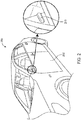
- FIG. 2 is a perspective view of a car with an illustrative rearview camera in accordance with an embodiment.
- Car 200 has a car door such as door 202, and as shown in the close-up view, rearview camera 210 may be mounted on door 202.
- Camera 210 that is mounted on car door 202 and facing towards the back of car 200 in the example of FIG. 2 is merely illustrative and does not serve to limit the scope of the present embodiments.
- camera 210 may be mounted on any other car door, on the trunk, on the engine hood facing forward, on the dashboard, on the front or back bumper, on the car door handles, on the housing of the car, or on any other suitable portion of car 200 facing any desired direction.
- FIG. 3 is a diagram showing how a rearview camera can include multiple target sampling points for detecting oncoming cars in an adjacent lane in accordance with an embodiment.
- the rearview camera is at least capable of capturing objects in a current lane 302 in which car 200 is presently driving on and also objects in an adjacent lane 304.
- each video frame 300 may include at least an array of target points 308 for detecting cars in adjacent lane 304.
- the position of target points 308 may be strategically selected such that it corresponds to the driver's "blind spot" in the context of the conventional optical rearview mirror or can be dynamically adjusted over time to adapt to changing conditions (e.g., to account for lane width variations, the current speed of the car, or other factors).
- Array 308 may include a first row 310-1 of points, a second row 310-2 of points, a third row 310-3 of points, and a fourth row 310-4 of points. Brightness measurements can be taken at these target points. These measurements can then be filtered using the long average filter to identify the road conditions and also filtered using the short average filter to identify "fast" moving object like cars passing through adjacent lane 304.
- a car such as car 306 may be detected in adjacent lane 304.
- row 310-1 may sense the car entering the array
- row 310-2 may then sense the car moving through the array
- row 310-3 may then be triggered
- row 310-4 is triggered.
- the camera will know that car 306 is quickly approaching from behind.
- row 310-4 may sense the car entering the array
- row 310-3 may then sense the car moving through the array
- row 310-2 may then be triggered, and then row 310-1 is triggered.
- the camera will know that car 200 (i.e., the car on which the camera is mounted) is actually overtaking car 306 in the adjacent lane.
- car 306 may be sporadically moving around within array 308 (i.e., randomly triggering row 310-1 or row 310-4, which may indicate that car 306 is moving at approximately the same speed as car 200 and is hovering in the driver's blinds spot.
- video frame 300 may also include an additional set of points 314 for detecting a car such as car 312 that is further back in adjacent lane 304.
- Points 314 may optionally be organized into multiple rows as described above to help determine the directionality of car 312. This might be helpful if car 312 is moving extremely quickly towards car 200, giving array 308 an even better chance at predicting the movement of an oncoming car in the adjacent lane.
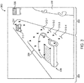
- FIG. 4 is a diagram showing how a video frame 400 captured by a rearview camera can include multiple target points for detecting rear collision.
- This particular camera may be mounted on the trunk, back bumper, or any other portion of the car's housing.
- frame 400 may include an array of target points 412.
- array 412 may be divided into a first row of points 410-1, a second row of points 410-2, and a third row of points 410-3.
- Brightness or light intensity measurements can be taken at each of these target points. The intensity measurements can then be filtered using the long average filter to identify the road conditions and also filtered using the short average filter to identify "fast" moving object like cars that are quickly approaching from behind.
- a car such as car 402 may be detected in the same lane from behind.
- row 410-1 may sense the car entering the array
- row 410-2 may then sense the car moving through the array
- row 410-3 may then be triggered.
- array 412 may sense that the car is leaving array 402, which is indicative of car 402 either slowing down relative to the camera or changing into another lane.
- car 402 may be sporadically moving around within array 412 (i.e., randomly triggering row 410-1 or row 410-3, which may indicate that car 402 is moving at approximately the same speed as car 200 and is tailgating (and perhaps dangerously closely) from behind.
- FIG. 5 is a diagram showing how a video frame 500 captured by a rearview camera can include multiple target points for cross traffic alert.
- This particular camera may be mounted on the engine hood, front bumper, or any other portion of the car's housing.
- frame 500 may include an array of target points 512.
- array 512 may be divided into a first column of points 510-1, a second column of points 510-2, and a third column of points 510-3.
- Brightness or light intensity measurements can be taken at each of these target points. The brightness measurements can then be filtered using the long average filter to identify the road conditions and also filtered using the short average filter to identify "fast" moving object like cars that are quickly moving from left to right or vice versa (from the driver's perspective).
- a car such as car 502 moving from left to right in the direction of arrow 503 may be detected.
- column 510-1 may sense the car entering the array
- column 510-2 may then sense the car moving through the array
- column 510-3 may then be triggered.
- the camera will know that car 502 is quickly moving from left to right.
- a similar array of target points can also be included on the right portion of frame 500 to help detect a car that is quickly moving from right to left.
- automotive system 100 may include camera 102 for capturing video frames having any desired number of arrays of target points, where each array can include any suitable number of rows or columns of target points for sensing the movement of objects across the frame in any desired direction relative to system 100.
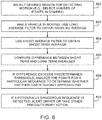
- FIG. 6 is a flow chart of illustrative steps for operating a motion sensor such as camera 102 on car 100.
- a desired region in the video frame may be selected for detecting motion (e.g., a number of points may be selected for measuring brightness levels in the camera).
- a region of target points may be selected for detecting oncoming cars in an adjacent lane (see, e.g., FIG. 3 ).
- a region of target points may be selected for detecting rear-end collision (see, e.g., FIG. 4 ).
- a region of target points may be selected for detecting cross-traffic (see, e.g., FIG. 5 ).
- long average filter 104 may be used to obtain a baseline average measurement while car 100 is moving.
- the baseline average measurement serves to detect slow-changing road conditions or weather conditions (as examples).
- short average filter 106 may be used to obtain a short term average measurement while car 100 is moving.
- the short term average serves to detect fast-changing and potentially unsafe conditions, such as when a car or other external obstacles are moving towards car 100 at a fast pace (relative to the baseline measurements).
- a signal processor associated with the camera may compute the difference between the short term average measurement and the baseline average measure. If this computed difference exceeds a predetermined threshold level, the camera may determine whether the target points have been activated in a particular sequence (step 608).
- the camera may issue an alert to the driver and take other precautionary action (step 610). For example, if the camera detects that a car is quickly approaching from an adjacent lane, the camera may issue an alert to the driver so that the driver may decide not to change lanes or the car may actually prevent the driver from changing lanes (e.g., by mechanically locking the steering wheel so as to prevent a potential collision).
- the camera may issue an alert to the driver so that the driver may somehow avoid the rear-end collision or if the collision is inevitable, the car may take other suitable action to minimize the impact (e.g., by applying brakes in a smart way so the car does not spin out of control or so that the car does not come to a sudden stop).
- the camera may again issue an alert to the driver so that the driver can somehow avoid entering the intersection out-of-turn or if the driver is unaware, the car may automatically apply brakes to prevent the car from entering the intersection.
- steps are merely illustrative.
- the existing steps may be modified or omitted; some of the steps may be performed in parallel; additional steps may be added; and the order of certain steps may be reversed or altered.
Landscapes
- Engineering & Computer Science (AREA)
- Multimedia (AREA)
- General Physics & Mathematics (AREA)
- Physics & Mathematics (AREA)
- Theoretical Computer Science (AREA)
- Signal Processing (AREA)
- Computer Vision & Pattern Recognition (AREA)
- Mechanical Engineering (AREA)
- Radar, Positioning & Navigation (AREA)
- Remote Sensing (AREA)
- Traffic Control Systems (AREA)
- Image Analysis (AREA)
- Image Processing (AREA)
Abstract
Description
- Cars typically include standard optical rearview mirrors attached near the hinge of the driver and passenger doors. These conventional rearview mirrors protrude from the body of the car and are prone to collision, especially in tight spots. Traditional rearview mirrors also have a blind spot where the driver cannot see oncoming cars due to the limited field of view of the rearview mirrors.
- It is within this context that the embodiments described herein arise.
- This relates generally to an automotive system and, more particularly, to cars equipped with cameras for sensing motion in their vicinity. In accordance with an embodiment, a car may be provided with a camera that captures video frames. The camera may be a rearview camera, a front-view camera, or a side-view camera. An array of target sampling points may be selected in each of the video frames. The camera may measure the brightness level and/or color at each of the target sampling points in the array.
- The camera may also include a long average filter circuit and a short average filter circuit. The long average filter circuit may filter the measured brightness level over a first number of frames to produce a long term average value, whereas the short average filter circuit may filter the measured brightness level over a second number of frames that is at least ten or a hundred times less than the first number of frames to produce a short term average value. The long term average value serves as a baseline measurement to detect noise and road/weather conditions, whereas the short term average value is compared with the baseline measurement to determine whether an external object is indeed approaching the car.
- The camera may also be configured to analyze the sequence in which the array of target sampling points are activated. For example, the camera may determine the order in which rows in the array of target points are being activated/triggered. Depending on what sequence is being triggered, the camera can help detect for the presence of another vehicle in an adjacent lane, the presence of another vehicle directly behind the car, and can also sense the direction of another vehicle in front of the car. In response to determining that another vehicle is moving towards the camera in a potentially dangerous way, the camera may send an alert to the driver or can direct the car to take other suitable precautionary action to prevent collision.
- Further features of the invention, its nature and various advantages will be more apparent from the accompanying drawings and following detailed description.
-
-
FIG. 1 is a diagram of an illustrative automotive system having a motion sensor in accordance with an embodiment. -
FIG. 2 is a perspective view of a car with an illustrative rearview camera in accordance with an embodiment. -
FIG. 3 is a diagram showing how a rearview camera can include multiple target points for detecting oncoming cars in an adjacent lane in accordance with an embodiment. -
FIG. 4 is a diagram showing how a rearview camera can include multiple target points for rear collision detection accordance with an embodiment. -
FIG. 5 is a diagram showing how a front-view camera can include multiple target points for cross traffic alert accordance with an embodiment. -
FIG. 6 is a flow chart of illustrative steps for operating a motion sensor on a car in accordance with an embodiment. - Embodiments of the present invention relate to motion sensing and, more particularly, to detecting motion in the vicinity of an automotive system. In particular, a car may be provided with a camera that includes a long average filter and a short average filter for filtering brightness measurements at selected target sampling points. The long average filter serves to output long term pixel intensity at the target points, whereas the short average filter serves to output short term pixel intensity at the target points. By comparing the short term pixel intensity with the long term pixel intensity, the camera will be capable of filtering out background noise and detecting the direction of an oncoming vehicle.
- It will be recognized by one skilled in the art, that the present exemplary embodiments may be practiced without some or all of these specific details. In other instances, well-known operations have not been described in detail in order not to unnecessarily obscure the present embodiments.
-
FIG. 1 is a diagram of an illustrative automotive system such assystem 100.Automotive system 100 may be a car, automobile, motorcar, motorboat, machine, or other transportation vehicle that is powered by an engine. As shown inFIG. 1 ,automotive system 100 may include a motion sensor such as motion sensor 102 (e.g., an ultrasonic sensor) for detecting moving objects in the vicinity ofsystem 100. For example,motion sensor 102 may be a camera that captures video frames. By analyzing the change in the position of objects in the video frames, the camera may be used to detect whether an external object is moving towards or away fromsystem 100. - In accordance with an embodiment,
system 100 may include filtering circuits such as longaverage filter 104 and shortaverage filter 106. Longaverage filter 104 and shortaverage filter 106 may be infinite impulse response (IIR) filters for measuring the long term pixel intensity and the short term pixel intensity, respectively. In other words, longaverage filter 104 may output a brightness level that is averaged over a first (longer) duration, whereas shortaverage filter 106 may output a brightness level that is averaged over a second duration that is shorter than the first duration. As an example, the long average filter may produce brightness values that are averaged over hundreds of frames. The short average filter may, on the other hand, produce brightness values that are average over only two to three frames (as an example). In general, the duration of the long term averaging may be at least ten times or at least a hundred times longer than the short term averaging. - Configured in this way, long
average filter 104 may be used to filter out "slower" changes or noise in the background, such as changes in road markings, changes in road condition, changes in weather, and/or other non-critical environmental variations. On the other hand, shortaverage filter 106 may be used to isolate "faster" changes in the vicinity of the car, such as when another vehicle is quickly approaching from behind, when another vehicle is quickly approaching from the side, when another vehicle is quickly approaching from the front, when another vehicle is quickly approaching the car from any suitable direction, or for detecting any motion relative to the car. -
FIG. 2 is a perspective view of a car with an illustrative rearview camera in accordance with an embodiment.Car 200 has a car door such asdoor 202, and as shown in the close-up view,rearview camera 210 may be mounted ondoor 202.Camera 210 that is mounted oncar door 202 and facing towards the back ofcar 200 in the example ofFIG. 2 is merely illustrative and does not serve to limit the scope of the present embodiments. If desired,camera 210 may be mounted on any other car door, on the trunk, on the engine hood facing forward, on the dashboard, on the front or back bumper, on the car door handles, on the housing of the car, or on any other suitable portion ofcar 200 facing any desired direction. -
FIG. 3 is a diagram showing how a rearview camera can include multiple target sampling points for detecting oncoming cars in an adjacent lane in accordance with an embodiment. As shown inFIG. 3 , the rearview camera is at least capable of capturing objects in acurrent lane 302 in whichcar 200 is presently driving on and also objects in anadjacent lane 304. In particular, eachvideo frame 300 may include at least an array oftarget points 308 for detecting cars inadjacent lane 304. The position oftarget points 308 may be strategically selected such that it corresponds to the driver's "blind spot" in the context of the conventional optical rearview mirror or can be dynamically adjusted over time to adapt to changing conditions (e.g., to account for lane width variations, the current speed of the car, or other factors). -
Array 308 may include a first row 310-1 of points, a second row 310-2 of points, a third row 310-3 of points, and a fourth row 310-4 of points. Brightness measurements can be taken at these target points. These measurements can then be filtered using the long average filter to identify the road conditions and also filtered using the short average filter to identify "fast" moving object like cars passing throughadjacent lane 304. - For example, a car such as
car 306 may be detected inadjacent lane 304. In one scenario, row 310-1 may sense the car entering the array, row 310-2 may then sense the car moving through the array, row 310-3 may then be triggered, and then row 310-4 is triggered. When this particular activation sequence is detected, the camera will know thatcar 306 is quickly approaching from behind. In another scenario, row 310-4 may sense the car entering the array, row 310-3 may then sense the car moving through the array, row 310-2 may then be triggered, and then row 310-1 is triggered. When this particular activation sequence is detected, the camera will know that car 200 (i.e., the car on which the camera is mounted) is actually overtakingcar 306 in the adjacent lane. In yet another scenario,car 306 may be sporadically moving around within array 308 (i.e., randomly triggering row 310-1 or row 310-4, which may indicate thatcar 306 is moving at approximately the same speed ascar 200 and is hovering in the driver's blinds spot. - Still referring to
FIG. 3 ,video frame 300 may also include an additional set ofpoints 314 for detecting a car such ascar 312 that is further back inadjacent lane 304.Points 314 may optionally be organized into multiple rows as described above to help determine the directionality ofcar 312. This might be helpful ifcar 312 is moving extremely quickly towardscar 200, givingarray 308 an even better chance at predicting the movement of an oncoming car in the adjacent lane. - In some embodiments, it may also be desirable to detect the movement of a car such as
car 320 directly behindcar 200.FIG. 4 is a diagram showing how avideo frame 400 captured by a rearview camera can include multiple target points for detecting rear collision. This particular camera may be mounted on the trunk, back bumper, or any other portion of the car's housing. As shown inFIG. 4 ,frame 400 may include an array of target points 412. In particular,array 412 may be divided into a first row of points 410-1, a second row of points 410-2, and a third row of points 410-3. Brightness or light intensity measurements can be taken at each of these target points. The intensity measurements can then be filtered using the long average filter to identify the road conditions and also filtered using the short average filter to identify "fast" moving object like cars that are quickly approaching from behind. - For example, a car such as
car 402 may be detected in the same lane from behind. In one scenario, row 410-1 may sense the car entering the array, row 410-2 may then sense the car moving through the array, and row 410-3 may then be triggered. When this particular activation sequence is detected, the camera will know thatcar 402 is quickly approaching from behind, potentially risking a rear-end collision. In another scenario,array 412 may sense that the car is leavingarray 402, which is indicative ofcar 402 either slowing down relative to the camera or changing into another lane. In yet another scenario,car 402 may be sporadically moving around within array 412 (i.e., randomly triggering row 410-1 or row 410-3, which may indicate thatcar 402 is moving at approximately the same speed ascar 200 and is tailgating (and perhaps dangerously closely) from behind. - In yet other suitable arrangements, it may also be desirable to detect the movement of a car moving across a lane from the front.
FIG. 5 is a diagram showing how avideo frame 500 captured by a rearview camera can include multiple target points for cross traffic alert. This particular camera may be mounted on the engine hood, front bumper, or any other portion of the car's housing. As shown inFIG. 5 ,frame 500 may include an array of target points 512. In particular,array 512 may be divided into a first column of points 510-1, a second column of points 510-2, and a third column of points 510-3. Brightness or light intensity measurements can be taken at each of these target points. The brightness measurements can then be filtered using the long average filter to identify the road conditions and also filtered using the short average filter to identify "fast" moving object like cars that are quickly moving from left to right or vice versa (from the driver's perspective). - For example, a car such as
car 502 moving from left to right in the direction ofarrow 503 may be detected. In this scenario, column 510-1 may sense the car entering the array, column 510-2 may then sense the car moving through the array, and column 510-3 may then be triggered. When this particular activation sequence is detected, the camera will know thatcar 502 is quickly moving from left to right. A similar array of target points (not shown) can also be included on the right portion offrame 500 to help detect a car that is quickly moving from right to left. - The exemplary configurations of target points shown in
FIGS. 3-5 are merely illustrative and are not intended to limit the scope of the present embodiments. In general, automotive system 100 (FIG. 1 ) may includecamera 102 for capturing video frames having any desired number of arrays of target points, where each array can include any suitable number of rows or columns of target points for sensing the movement of objects across the frame in any desired direction relative tosystem 100. -
FIG. 6 is a flow chart of illustrative steps for operating a motion sensor such ascamera 102 oncar 100. Atstep 600, a desired region in the video frame may be selected for detecting motion (e.g., a number of points may be selected for measuring brightness levels in the camera). For example, a region of target points may be selected for detecting oncoming cars in an adjacent lane (see, e.g.,FIG. 3 ). As another example, a region of target points may be selected for detecting rear-end collision (see, e.g.,FIG. 4 ). As yet another example, a region of target points may be selected for detecting cross-traffic (see, e.g.,FIG. 5 ). - At
step 602, longaverage filter 104 may be used to obtain a baseline average measurement whilecar 100 is moving. The baseline average measurement serves to detect slow-changing road conditions or weather conditions (as examples). - At
step 604, shortaverage filter 106 may be used to obtain a short term average measurement whilecar 100 is moving. The short term average serves to detect fast-changing and potentially unsafe conditions, such as when a car or other external obstacles are moving towardscar 100 at a fast pace (relative to the baseline measurements). - At
step 606, a signal processor associated with the camera (e.g., a signal processor that may be part of the camera unit or may be a separate component) may compute the difference between the short term average measurement and the baseline average measure. If this computed difference exceeds a predetermined threshold level, the camera may determine whether the target points have been activated in a particular sequence (step 608). - If a potentially dangerous sequence has been detected, the camera may issue an alert to the driver and take other precautionary action (step 610). For example, if the camera detects that a car is quickly approaching from an adjacent lane, the camera may issue an alert to the driver so that the driver may decide not to change lanes or the car may actually prevent the driver from changing lanes (e.g., by mechanically locking the steering wheel so as to prevent a potential collision).
- As another example, if the camera detects that a car is quickly approaching from behind, the camera may issue an alert to the driver so that the driver may somehow avoid the rear-end collision or if the collision is inevitable, the car may take other suitable action to minimize the impact (e.g., by applying brakes in a smart way so the car does not spin out of control or so that the car does not come to a sudden stop).
- As yet another example, if the camera detects that a car is quickly approaching from an orthogonal lane (as in the intersection scenario shown in
FIG. 5 ), the camera may again issue an alert to the driver so that the driver can somehow avoid entering the intersection out-of-turn or if the driver is unaware, the car may automatically apply brakes to prevent the car from entering the intersection. - These steps are merely illustrative. The existing steps may be modified or omitted; some of the steps may be performed in parallel; additional steps may be added; and the order of certain steps may be reversed or altered.
- The embodiments described herein in which only two different filters are used to detect motion is merely illustrative and does not serve to limit the scope of the present invention. If desired, more than two filters may be used. In other suitable embodiments, at least three filters of different sensitivities may be used, at least four filters of different sensitivities may be used, at least five filters of different sensitivities may be used, etc.
- The foregoing is merely illustrative of the principles of this invention and various modifications can be made by those skilled in the art. The foregoing embodiments may be implemented individually or in any combination.
Claims (15)
- An automotive system, comprising:a camera for detecting motion in the vicinity of the automotive system, wherein the camera includes a first filter circuit and a second filter circuit, wherein the first filter circuit generates a first output, wherein the second filter circuit generates a second output, and wherein camera senses motion in the vicinity of the automotive system based on the first and second outputs.
- The automotive system of claim 1, wherein the camera is configured to capture a frame having a plurality of target points.
- The automotive system of claim 2, wherein the camera measures brightness levels at the plurality of target points.
- The automotive system of claim 2, wherein the plurality of target points are arranged in an array of rows and columns of target points.
- The automotive system of claim 4, wherein the camera analyzes a sequence in which the target points in the array are activated to determine whether another vehicle is approaching the automotive system.
- The automotive system of any one of claims 1-5, wherein the first filter circuit comprises a long average filter for generating a baseline measurement and, wherein the second filter circuit comprises a short average filter for generating a short term measurement that is compared with the baseline measurement.
- The automotive system of any one of claims 1-6, wherein the camera further includes a third filter that generates a third output, and wherein the camera senses motion in the vicinity of the automotive system based on the first, second, and third outputs.
- The automotive system of any one of claims 1-7, wherein the camera detects for the presence of another vehicle in an adjacent lane.
- The automotive system of any one of claims 1-8, wherein the camera detects for the presence of another vehicle directly behind the automotive system.
- The automotive system of any one of claims 1-9, wherein the camera senses the direction of another vehicle in front of the automotive system.
- A method for operating a camera in an automotive system, comprising:using the camera to capture an image;selecting a plurality of target sampling points in the image;measuring intensity levels at the plurality of target sampling points in the image;with a first filtering circuit, filtering the measured intensity levels to generate a first filtered output;with a second filtering circuit, filtering the measured intensity levels to generate a second filtered output; andsensing motion in the vicinity of the automotive system based on the first and second filtered outputs.
- The method of claim 11, wherein filtering the measured intensity levels to generate the first filter output comprises using a long average filter to produce a long term average value, and wherein filtering the measured intensity levels to generate the second filter output comprises using a short average filter to produce a short term average value.
- The method of any one of claims 11-12, wherein sensing the motion in the vicinity of the automotive system comprises computing a difference between the first and second filtered outputs.
- The method of claim 13, further comprising:comparing the computed difference to a predetermined threshold to determine whether a given target sampling point in the plurality of target sampling points has been activated.
- The method of claim 14, further comprising:in response to detecting that a particular sequence of target sampling points has been activated, taking suitable precautionary action to prevent collision.
Applications Claiming Priority (1)
| Application Number | Priority Date | Filing Date | Title |
|---|---|---|---|
| US15/369,716 US11017243B2 (en) | 2016-12-05 | 2016-12-05 | Automotive system with motion detection capabilities |
Publications (2)
| Publication Number | Publication Date |
|---|---|
| EP3330923A1 true EP3330923A1 (en) | 2018-06-06 |
| EP3330923B1 EP3330923B1 (en) | 2019-12-25 |
Family
ID=60262791
Family Applications (1)
| Application Number | Title | Priority Date | Filing Date |
|---|---|---|---|
| EP17200029.1A Active EP3330923B1 (en) | 2016-12-05 | 2017-11-03 | Automotive system with motion detection capabilities |
Country Status (3)
| Country | Link |
|---|---|
| US (1) | US11017243B2 (en) |
| EP (1) | EP3330923B1 (en) |
| CN (2) | CN108151714B (en) |
Cited By (1)
| Publication number | Priority date | Publication date | Assignee | Title |
|---|---|---|---|---|
| US11017243B2 (en) | 2016-12-05 | 2021-05-25 | Intel Corporation | Automotive system with motion detection capabilities |
Families Citing this family (4)
| Publication number | Priority date | Publication date | Assignee | Title |
|---|---|---|---|---|
| JP6760867B2 (en) * | 2017-02-20 | 2020-09-23 | 株式会社アルファ | Peripheral monitoring device for vehicles |
| CN112970029B (en) * | 2018-09-13 | 2024-06-07 | 辉达公司 | Deep neural network processing for sensor blind detection in autonomous machine applications |
| US11893753B2 (en) * | 2019-08-27 | 2024-02-06 | Pixart Imaging Inc. | Security camera and motion detecting method for security camera |
| US20220353489A1 (en) * | 2021-04-30 | 2022-11-03 | Microsoft Technology Licensing, Llc | Systems and methods for efficient generation of single photon avalanche diode imagery with persistence |
Citations (2)
| Publication number | Priority date | Publication date | Assignee | Title |
|---|---|---|---|---|
| US20120095628A1 (en) * | 2006-11-30 | 2012-04-19 | Ab Volvo Penta | Safety system for marine vessels |
| US20160328629A1 (en) * | 2013-02-01 | 2016-11-10 | Eric Sinclair | Systems and methods for traffic event detection for vehicles using rolling averages |
Family Cites Families (16)
| Publication number | Priority date | Publication date | Assignee | Title |
|---|---|---|---|---|
| US3120992A (en) | 1960-06-16 | 1964-02-11 | Hollingsworth R Lee | Automobile traffic surveillance apparatus and speed measurement equipment |
| DE69330513D1 (en) | 1992-03-20 | 2001-09-06 | Commw Scient Ind Res Org | OBJECT MONITORING SYSTEM |
| JP4800455B2 (en) | 1999-02-19 | 2011-10-26 | 富士通株式会社 | Vehicle speed measuring method and apparatus |
| AU2003225228A1 (en) * | 2002-05-03 | 2003-11-17 | Donnelly Corporation | Object detection system for vehicle |
| EP1551178A1 (en) * | 2003-12-18 | 2005-07-06 | Koninklijke Philips Electronics N.V. | Supplementary visual display system |
| US7231288B2 (en) | 2005-03-15 | 2007-06-12 | Visteon Global Technologies, Inc. | System to determine distance to a lead vehicle |
| US7834910B2 (en) * | 2006-03-01 | 2010-11-16 | David M. DeLorme | Method and apparatus for panoramic imaging |
| CN100574376C (en) * | 2006-03-27 | 2009-12-23 | 精工爱普生株式会社 | Camera head, camera system and image capture method |
| US7676324B2 (en) | 2006-05-25 | 2010-03-09 | Gm Global Technology Operations, Inc. | Alerting a vehicle operator to traffic movement |
| DE102012217093A1 (en) | 2012-09-21 | 2014-04-17 | Robert Bosch Gmbh | Camera system, in particular for a vehicle, and method for determining image information of a detection area |
| DE102012023030A1 (en) * | 2012-11-26 | 2014-05-28 | Audi Ag | Method for determining the movement of a motor vehicle |
| CN105191288B (en) * | 2012-12-31 | 2018-10-16 | 菲力尔系统公司 | Abnormal pixel detects |
| US8908090B2 (en) | 2013-03-15 | 2014-12-09 | Freefly Systems, Inc. | Method for enabling manual adjustment of a pointing direction of an actively stabilized camera |
| EP2821308B1 (en) | 2013-07-03 | 2016-09-28 | Volvo Car Corporation | Vehicle system for control of vehicle safety parameters, a vehicle and a method for controlling safety parameters |
| DE102015202376A1 (en) | 2015-02-11 | 2016-08-11 | Conti Temic Microelectronic Gmbh | Driver assistance system |
| US11017243B2 (en) | 2016-12-05 | 2021-05-25 | Intel Corporation | Automotive system with motion detection capabilities |
-
2016
- 2016-12-05 US US15/369,716 patent/US11017243B2/en active Active
-
2017
- 2017-11-03 EP EP17200029.1A patent/EP3330923B1/en active Active
- 2017-12-05 CN CN201711266837.0A patent/CN108151714B/en active Active
- 2017-12-05 CN CN202210965073.9A patent/CN115265495B/en active Active
Patent Citations (2)
| Publication number | Priority date | Publication date | Assignee | Title |
|---|---|---|---|---|
| US20120095628A1 (en) * | 2006-11-30 | 2012-04-19 | Ab Volvo Penta | Safety system for marine vessels |
| US20160328629A1 (en) * | 2013-02-01 | 2016-11-10 | Eric Sinclair | Systems and methods for traffic event detection for vehicles using rolling averages |
Cited By (1)
| Publication number | Priority date | Publication date | Assignee | Title |
|---|---|---|---|---|
| US11017243B2 (en) | 2016-12-05 | 2021-05-25 | Intel Corporation | Automotive system with motion detection capabilities |
Also Published As
| Publication number | Publication date |
|---|---|
| US20180157919A1 (en) | 2018-06-07 |
| EP3330923B1 (en) | 2019-12-25 |
| CN108151714B (en) | 2022-09-06 |
| CN108151714A (en) | 2018-06-12 |
| US11017243B2 (en) | 2021-05-25 |
| CN115265495A (en) | 2022-11-01 |
| CN115265495B (en) | 2026-04-21 |
Similar Documents
| Publication | Publication Date | Title |
|---|---|---|
| EP3330923A1 (en) | Automotive system with motion detection capabilities | |
| US9726483B2 (en) | Integrated vehicular system for low speed collision avoidance | |
| EP2150437B1 (en) | Rear obstruction detection | |
| US7772991B2 (en) | Accident avoidance during vehicle backup | |
| EP2579231A1 (en) | Image processing apparatus for vehicle | |
| EP3139340B1 (en) | System and method for visibility enhancement | |
| KR20180065527A (en) | Vehicle side-rear warning device and method using the same | |
| US7876204B2 (en) | Thermal radiation detector | |
| EP2083410B1 (en) | Vehicle zone detection system and method | |
| CN110446631A (en) | Devices for triggering external protective functions | |
| JP4751894B2 (en) | A system to detect obstacles in front of a car | |
| US20110242318A1 (en) | System and method for monitoring blind spots of vehicles | |
| US11648876B2 (en) | System and method for visibility enhancement | |
| US20210321062A1 (en) | Image processing device in moving object, imaging device, image processing method, and recording medium | |
| KR20120103980A (en) | Apparatus and method for alarming blind spot of preceding vehicle | |
| KR101750201B1 (en) | Blind spot detection device using behavior of vehicle | |
| JP7194890B2 (en) | car mirror device | |
| KR101684782B1 (en) | Rain sensing type wiper apparatus | |
| Su et al. | Design and implementation for an automotive DOA system | |
| JP2000261795A (en) | Rear side monitoring device for vehicles | |
| JP2024016501A (en) | Vehicle-mounted camera shielding state determination device | |
| JP2022166499A (en) | image recorder | |
| JP2023109222A (en) | Mobile body detection device, vehicle and mobile body detection method |
Legal Events
| Date | Code | Title | Description |
|---|---|---|---|
| PUAI | Public reference made under article 153(3) epc to a published international application that has entered the european phase |
Free format text: ORIGINAL CODE: 0009012 |
|
| STAA | Information on the status of an ep patent application or granted ep patent |
Free format text: STATUS: REQUEST FOR EXAMINATION WAS MADE |
|
| 17P | Request for examination filed |
Effective date: 20171103 |
|
| AK | Designated contracting states |
Kind code of ref document: A1 Designated state(s): AL AT BE BG CH CY CZ DE DK EE ES FI FR GB GR HR HU IE IS IT LI LT LU LV MC MK MT NL NO PL PT RO RS SE SI SK SM TR |
|
| AX | Request for extension of the european patent |
Extension state: BA ME |
|
| STAA | Information on the status of an ep patent application or granted ep patent |
Free format text: STATUS: EXAMINATION IS IN PROGRESS |
|
| 17Q | First examination report despatched |
Effective date: 20190227 |
|
| GRAP | Despatch of communication of intention to grant a patent |
Free format text: ORIGINAL CODE: EPIDOSNIGR1 |
|
| STAA | Information on the status of an ep patent application or granted ep patent |
Free format text: STATUS: GRANT OF PATENT IS INTENDED |
|
| INTG | Intention to grant announced |
Effective date: 20190603 |
|
| GRAS | Grant fee paid |
Free format text: ORIGINAL CODE: EPIDOSNIGR3 |
|
| GRAA | (expected) grant |
Free format text: ORIGINAL CODE: 0009210 |
|
| STAA | Information on the status of an ep patent application or granted ep patent |
Free format text: STATUS: THE PATENT HAS BEEN GRANTED |
|
| AK | Designated contracting states |
Kind code of ref document: B1 Designated state(s): AL AT BE BG CH CY CZ DE DK EE ES FI FR GB GR HR HU IE IS IT LI LT LU LV MC MK MT NL NO PL PT RO RS SE SI SK SM TR |
|
| REG | Reference to a national code |
Ref country code: GB Ref legal event code: FG4D |
|
| REG | Reference to a national code |
Ref country code: CH Ref legal event code: EP |
|
| REG | Reference to a national code |
Ref country code: DE Ref legal event code: R096 Ref document number: 602017010054 Country of ref document: DE |
|
| REG | Reference to a national code |
Ref country code: AT Ref legal event code: REF Ref document number: 1217960 Country of ref document: AT Kind code of ref document: T Effective date: 20200115 |
|
| REG | Reference to a national code |
Ref country code: IE Ref legal event code: FG4D |
|
| REG | Reference to a national code |
Ref country code: NL Ref legal event code: FP |
|
| PG25 | Lapsed in a contracting state [announced via postgrant information from national office to epo] |
Ref country code: FI Free format text: LAPSE BECAUSE OF FAILURE TO SUBMIT A TRANSLATION OF THE DESCRIPTION OR TO PAY THE FEE WITHIN THE PRESCRIBED TIME-LIMIT Effective date: 20191225 Ref country code: BG Free format text: LAPSE BECAUSE OF FAILURE TO SUBMIT A TRANSLATION OF THE DESCRIPTION OR TO PAY THE FEE WITHIN THE PRESCRIBED TIME-LIMIT Effective date: 20200325 Ref country code: LV Free format text: LAPSE BECAUSE OF FAILURE TO SUBMIT A TRANSLATION OF THE DESCRIPTION OR TO PAY THE FEE WITHIN THE PRESCRIBED TIME-LIMIT Effective date: 20191225 Ref country code: SE Free format text: LAPSE BECAUSE OF FAILURE TO SUBMIT A TRANSLATION OF THE DESCRIPTION OR TO PAY THE FEE WITHIN THE PRESCRIBED TIME-LIMIT Effective date: 20191225 Ref country code: NO Free format text: LAPSE BECAUSE OF FAILURE TO SUBMIT A TRANSLATION OF THE DESCRIPTION OR TO PAY THE FEE WITHIN THE PRESCRIBED TIME-LIMIT Effective date: 20200325 Ref country code: LT Free format text: LAPSE BECAUSE OF FAILURE TO SUBMIT A TRANSLATION OF THE DESCRIPTION OR TO PAY THE FEE WITHIN THE PRESCRIBED TIME-LIMIT Effective date: 20191225 Ref country code: GR Free format text: LAPSE BECAUSE OF FAILURE TO SUBMIT A TRANSLATION OF THE DESCRIPTION OR TO PAY THE FEE WITHIN THE PRESCRIBED TIME-LIMIT Effective date: 20200326 |
|
| REG | Reference to a national code |
Ref country code: LT Ref legal event code: MG4D |
|
| PG25 | Lapsed in a contracting state [announced via postgrant information from national office to epo] |
Ref country code: HR Free format text: LAPSE BECAUSE OF FAILURE TO SUBMIT A TRANSLATION OF THE DESCRIPTION OR TO PAY THE FEE WITHIN THE PRESCRIBED TIME-LIMIT Effective date: 20191225 Ref country code: RS Free format text: LAPSE BECAUSE OF FAILURE TO SUBMIT A TRANSLATION OF THE DESCRIPTION OR TO PAY THE FEE WITHIN THE PRESCRIBED TIME-LIMIT Effective date: 20191225 |
|
| PG25 | Lapsed in a contracting state [announced via postgrant information from national office to epo] |
Ref country code: AL Free format text: LAPSE BECAUSE OF FAILURE TO SUBMIT A TRANSLATION OF THE DESCRIPTION OR TO PAY THE FEE WITHIN THE PRESCRIBED TIME-LIMIT Effective date: 20191225 |
|
| PG25 | Lapsed in a contracting state [announced via postgrant information from national office to epo] |
Ref country code: EE Free format text: LAPSE BECAUSE OF FAILURE TO SUBMIT A TRANSLATION OF THE DESCRIPTION OR TO PAY THE FEE WITHIN THE PRESCRIBED TIME-LIMIT Effective date: 20191225 Ref country code: PT Free format text: LAPSE BECAUSE OF FAILURE TO SUBMIT A TRANSLATION OF THE DESCRIPTION OR TO PAY THE FEE WITHIN THE PRESCRIBED TIME-LIMIT Effective date: 20200520 Ref country code: CZ Free format text: LAPSE BECAUSE OF FAILURE TO SUBMIT A TRANSLATION OF THE DESCRIPTION OR TO PAY THE FEE WITHIN THE PRESCRIBED TIME-LIMIT Effective date: 20191225 Ref country code: RO Free format text: LAPSE BECAUSE OF FAILURE TO SUBMIT A TRANSLATION OF THE DESCRIPTION OR TO PAY THE FEE WITHIN THE PRESCRIBED TIME-LIMIT Effective date: 20191225 |
|
| PG25 | Lapsed in a contracting state [announced via postgrant information from national office to epo] |
Ref country code: IS Free format text: LAPSE BECAUSE OF FAILURE TO SUBMIT A TRANSLATION OF THE DESCRIPTION OR TO PAY THE FEE WITHIN THE PRESCRIBED TIME-LIMIT Effective date: 20200425 Ref country code: SK Free format text: LAPSE BECAUSE OF FAILURE TO SUBMIT A TRANSLATION OF THE DESCRIPTION OR TO PAY THE FEE WITHIN THE PRESCRIBED TIME-LIMIT Effective date: 20191225 Ref country code: SM Free format text: LAPSE BECAUSE OF FAILURE TO SUBMIT A TRANSLATION OF THE DESCRIPTION OR TO PAY THE FEE WITHIN THE PRESCRIBED TIME-LIMIT Effective date: 20191225 |
|
| REG | Reference to a national code |
Ref country code: DE Ref legal event code: R097 Ref document number: 602017010054 Country of ref document: DE |
|
| PG25 | Lapsed in a contracting state [announced via postgrant information from national office to epo] |
Ref country code: ES Free format text: LAPSE BECAUSE OF FAILURE TO SUBMIT A TRANSLATION OF THE DESCRIPTION OR TO PAY THE FEE WITHIN THE PRESCRIBED TIME-LIMIT Effective date: 20191225 Ref country code: DK Free format text: LAPSE BECAUSE OF FAILURE TO SUBMIT A TRANSLATION OF THE DESCRIPTION OR TO PAY THE FEE WITHIN THE PRESCRIBED TIME-LIMIT Effective date: 20191225 |
|
| PLBE | No opposition filed within time limit |
Free format text: ORIGINAL CODE: 0009261 |
|
| STAA | Information on the status of an ep patent application or granted ep patent |
Free format text: STATUS: NO OPPOSITION FILED WITHIN TIME LIMIT |
|
| REG | Reference to a national code |
Ref country code: AT Ref legal event code: MK05 Ref document number: 1217960 Country of ref document: AT Kind code of ref document: T Effective date: 20191225 |
|
| PG25 | Lapsed in a contracting state [announced via postgrant information from national office to epo] |
Ref country code: SI Free format text: LAPSE BECAUSE OF FAILURE TO SUBMIT A TRANSLATION OF THE DESCRIPTION OR TO PAY THE FEE WITHIN THE PRESCRIBED TIME-LIMIT Effective date: 20191225 |
|
| 26N | No opposition filed |
Effective date: 20200928 |
|
| PG25 | Lapsed in a contracting state [announced via postgrant information from national office to epo] |
Ref country code: AT Free format text: LAPSE BECAUSE OF FAILURE TO SUBMIT A TRANSLATION OF THE DESCRIPTION OR TO PAY THE FEE WITHIN THE PRESCRIBED TIME-LIMIT Effective date: 20191225 Ref country code: IT Free format text: LAPSE BECAUSE OF FAILURE TO SUBMIT A TRANSLATION OF THE DESCRIPTION OR TO PAY THE FEE WITHIN THE PRESCRIBED TIME-LIMIT Effective date: 20191225 |
|
| PG25 | Lapsed in a contracting state [announced via postgrant information from national office to epo] |
Ref country code: PL Free format text: LAPSE BECAUSE OF FAILURE TO SUBMIT A TRANSLATION OF THE DESCRIPTION OR TO PAY THE FEE WITHIN THE PRESCRIBED TIME-LIMIT Effective date: 20191225 |
|
| PG25 | Lapsed in a contracting state [announced via postgrant information from national office to epo] |
Ref country code: MC Free format text: LAPSE BECAUSE OF FAILURE TO SUBMIT A TRANSLATION OF THE DESCRIPTION OR TO PAY THE FEE WITHIN THE PRESCRIBED TIME-LIMIT Effective date: 20191225 |
|
| REG | Reference to a national code |
Ref country code: CH Ref legal event code: PL |
|
| PG25 | Lapsed in a contracting state [announced via postgrant information from national office to epo] |
Ref country code: LU Free format text: LAPSE BECAUSE OF NON-PAYMENT OF DUE FEES Effective date: 20201103 |
|
| REG | Reference to a national code |
Ref country code: BE Ref legal event code: MM Effective date: 20201130 |
|
| PG25 | Lapsed in a contracting state [announced via postgrant information from national office to epo] |
Ref country code: CH Free format text: LAPSE BECAUSE OF NON-PAYMENT OF DUE FEES Effective date: 20201130 Ref country code: LI Free format text: LAPSE BECAUSE OF NON-PAYMENT OF DUE FEES Effective date: 20201130 |
|
| PG25 | Lapsed in a contracting state [announced via postgrant information from national office to epo] |
Ref country code: IE Free format text: LAPSE BECAUSE OF NON-PAYMENT OF DUE FEES Effective date: 20201103 |
|
| PGFP | Annual fee paid to national office [announced via postgrant information from national office to epo] |
Ref country code: NL Payment date: 20211025 Year of fee payment: 5 |
|
| PGFP | Annual fee paid to national office [announced via postgrant information from national office to epo] |
Ref country code: DE Payment date: 20211019 Year of fee payment: 5 |
|
| PGFP | Annual fee paid to national office [announced via postgrant information from national office to epo] |
Ref country code: FR Payment date: 20211029 Year of fee payment: 5 |
|
| PG25 | Lapsed in a contracting state [announced via postgrant information from national office to epo] |
Ref country code: TR Free format text: LAPSE BECAUSE OF FAILURE TO SUBMIT A TRANSLATION OF THE DESCRIPTION OR TO PAY THE FEE WITHIN THE PRESCRIBED TIME-LIMIT Effective date: 20191225 Ref country code: MT Free format text: LAPSE BECAUSE OF FAILURE TO SUBMIT A TRANSLATION OF THE DESCRIPTION OR TO PAY THE FEE WITHIN THE PRESCRIBED TIME-LIMIT Effective date: 20191225 Ref country code: CY Free format text: LAPSE BECAUSE OF FAILURE TO SUBMIT A TRANSLATION OF THE DESCRIPTION OR TO PAY THE FEE WITHIN THE PRESCRIBED TIME-LIMIT Effective date: 20191225 |
|
| PG25 | Lapsed in a contracting state [announced via postgrant information from national office to epo] |
Ref country code: MK Free format text: LAPSE BECAUSE OF FAILURE TO SUBMIT A TRANSLATION OF THE DESCRIPTION OR TO PAY THE FEE WITHIN THE PRESCRIBED TIME-LIMIT Effective date: 20191225 |
|
| GBPC | Gb: european patent ceased through non-payment of renewal fee |
Effective date: 20211103 |
|
| PG25 | Lapsed in a contracting state [announced via postgrant information from national office to epo] |
Ref country code: BE Free format text: LAPSE BECAUSE OF NON-PAYMENT OF DUE FEES Effective date: 20201130 |
|
| PG25 | Lapsed in a contracting state [announced via postgrant information from national office to epo] |
Ref country code: GB Free format text: LAPSE BECAUSE OF NON-PAYMENT OF DUE FEES Effective date: 20211103 |
|
| REG | Reference to a national code |
Ref country code: DE Ref legal event code: R119 Ref document number: 602017010054 Country of ref document: DE |
|
| P01 | Opt-out of the competence of the unified patent court (upc) registered |
Effective date: 20230518 |
|
| REG | Reference to a national code |
Ref country code: NL Ref legal event code: MM Effective date: 20221201 |
|
| PG25 | Lapsed in a contracting state [announced via postgrant information from national office to epo] |
Ref country code: NL Free format text: LAPSE BECAUSE OF NON-PAYMENT OF DUE FEES Effective date: 20221201 |
|
| PG25 | Lapsed in a contracting state [announced via postgrant information from national office to epo] |
Ref country code: DE Free format text: LAPSE BECAUSE OF NON-PAYMENT OF DUE FEES Effective date: 20230601 |
|
| PG25 | Lapsed in a contracting state [announced via postgrant information from national office to epo] |
Ref country code: FR Free format text: LAPSE BECAUSE OF NON-PAYMENT OF DUE FEES Effective date: 20221130 |