EP3330558A1 - Rotational power transmission mechanism and heat treatment furnace - Google Patents
Rotational power transmission mechanism and heat treatment furnace Download PDFInfo
- Publication number
- EP3330558A1 EP3330558A1 EP17199013.8A EP17199013A EP3330558A1 EP 3330558 A1 EP3330558 A1 EP 3330558A1 EP 17199013 A EP17199013 A EP 17199013A EP 3330558 A1 EP3330558 A1 EP 3330558A1
- Authority
- EP
- European Patent Office
- Prior art keywords
- rotary member
- rotational power
- transmission mechanism
- power transmission
- output shaft
- Prior art date
- Legal status (The legal status is an assumption and is not a legal conclusion. Google has not performed a legal analysis and makes no representation as to the accuracy of the status listed.)
- Withdrawn
Links
- 230000005540 biological transmission Effects 0.000 title claims abstract description 29
- 238000010438 heat treatment Methods 0.000 title claims description 12
- 230000002940 repellent Effects 0.000 description 9
- 239000005871 repellent Substances 0.000 description 9
- 230000004907 flux Effects 0.000 description 3
- 238000009413 insulation Methods 0.000 description 1
Images


Classifications
-
- H—ELECTRICITY
- H02—GENERATION; CONVERSION OR DISTRIBUTION OF ELECTRIC POWER
- H02K—DYNAMO-ELECTRIC MACHINES
- H02K49/00—Dynamo-electric clutches; Dynamo-electric brakes
- H02K49/10—Dynamo-electric clutches; Dynamo-electric brakes of the permanent-magnet type
- H02K49/102—Magnetic gearings, i.e. assembly of gears, linear or rotary, by which motion is magnetically transferred without physical contact
-
- F—MECHANICAL ENGINEERING; LIGHTING; HEATING; WEAPONS; BLASTING
- F16—ENGINEERING ELEMENTS AND UNITS; GENERAL MEASURES FOR PRODUCING AND MAINTAINING EFFECTIVE FUNCTIONING OF MACHINES OR INSTALLATIONS; THERMAL INSULATION IN GENERAL
- F16H—GEARING
- F16H57/00—General details of gearing
- F16H57/02—Gearboxes; Mounting gearing therein
- F16H57/023—Mounting or installation of gears or shafts in the gearboxes, e.g. methods or means for assembly
-
- F—MECHANICAL ENGINEERING; LIGHTING; HEATING; WEAPONS; BLASTING
- F16—ENGINEERING ELEMENTS AND UNITS; GENERAL MEASURES FOR PRODUCING AND MAINTAINING EFFECTIVE FUNCTIONING OF MACHINES OR INSTALLATIONS; THERMAL INSULATION IN GENERAL
- F16D—COUPLINGS FOR TRANSMITTING ROTATION; CLUTCHES; BRAKES
- F16D3/00—Yielding couplings, i.e. with means permitting movement between the connected parts during the drive
- F16D3/02—Yielding couplings, i.e. with means permitting movement between the connected parts during the drive adapted to specific functions
- F16D3/12—Yielding couplings, i.e. with means permitting movement between the connected parts during the drive adapted to specific functions specially adapted for accumulation of energy to absorb shocks or vibration
-
- C—CHEMISTRY; METALLURGY
- C21—METALLURGY OF IRON
- C21D—MODIFYING THE PHYSICAL STRUCTURE OF FERROUS METALS; GENERAL DEVICES FOR HEAT TREATMENT OF FERROUS OR NON-FERROUS METALS OR ALLOYS; MAKING METAL MALLEABLE, e.g. BY DECARBURISATION OR TEMPERING
- C21D9/00—Heat treatment, e.g. annealing, hardening, quenching or tempering, adapted for particular articles; Furnaces therefor
- C21D9/0006—Details, accessories not peculiar to any of the following furnaces
-
- F—MECHANICAL ENGINEERING; LIGHTING; HEATING; WEAPONS; BLASTING
- F16—ENGINEERING ELEMENTS AND UNITS; GENERAL MEASURES FOR PRODUCING AND MAINTAINING EFFECTIVE FUNCTIONING OF MACHINES OR INSTALLATIONS; THERMAL INSULATION IN GENERAL
- F16D—COUPLINGS FOR TRANSMITTING ROTATION; CLUTCHES; BRAKES
- F16D3/00—Yielding couplings, i.e. with means permitting movement between the connected parts during the drive
- F16D3/02—Yielding couplings, i.e. with means permitting movement between the connected parts during the drive adapted to specific functions
- F16D3/10—Couplings with means for varying the angular relationship of two coaxial shafts during motion
-
- F—MECHANICAL ENGINEERING; LIGHTING; HEATING; WEAPONS; BLASTING
- F16—ENGINEERING ELEMENTS AND UNITS; GENERAL MEASURES FOR PRODUCING AND MAINTAINING EFFECTIVE FUNCTIONING OF MACHINES OR INSTALLATIONS; THERMAL INSULATION IN GENERAL
- F16D—COUPLINGS FOR TRANSMITTING ROTATION; CLUTCHES; BRAKES
- F16D3/00—Yielding couplings, i.e. with means permitting movement between the connected parts during the drive
- F16D3/50—Yielding couplings, i.e. with means permitting movement between the connected parts during the drive with the coupling parts connected by one or more intermediate members
- F16D3/64—Yielding couplings, i.e. with means permitting movement between the connected parts during the drive with the coupling parts connected by one or more intermediate members comprising elastic elements arranged between substantially-radial walls of both coupling parts
-
- F—MECHANICAL ENGINEERING; LIGHTING; HEATING; WEAPONS; BLASTING
- F16—ENGINEERING ELEMENTS AND UNITS; GENERAL MEASURES FOR PRODUCING AND MAINTAINING EFFECTIVE FUNCTIONING OF MACHINES OR INSTALLATIONS; THERMAL INSULATION IN GENERAL
- F16H—GEARING
- F16H49/00—Other gearings
-
- H—ELECTRICITY
- H02—GENERATION; CONVERSION OR DISTRIBUTION OF ELECTRIC POWER
- H02K—DYNAMO-ELECTRIC MACHINES
- H02K49/00—Dynamo-electric clutches; Dynamo-electric brakes
- H02K49/10—Dynamo-electric clutches; Dynamo-electric brakes of the permanent-magnet type
- H02K49/104—Magnetic couplings consisting of only two coaxial rotary elements, i.e. the driving element and the driven element
-
- H—ELECTRICITY
- H02—GENERATION; CONVERSION OR DISTRIBUTION OF ELECTRIC POWER
- H02K—DYNAMO-ELECTRIC MACHINES
- H02K49/00—Dynamo-electric clutches; Dynamo-electric brakes
- H02K49/10—Dynamo-electric clutches; Dynamo-electric brakes of the permanent-magnet type
- H02K49/104—Magnetic couplings consisting of only two coaxial rotary elements, i.e. the driving element and the driven element
- H02K49/106—Magnetic couplings consisting of only two coaxial rotary elements, i.e. the driving element and the driven element with a radial air gap
-
- H—ELECTRICITY
- H02—GENERATION; CONVERSION OR DISTRIBUTION OF ELECTRIC POWER
- H02K—DYNAMO-ELECTRIC MACHINES
- H02K49/00—Dynamo-electric clutches; Dynamo-electric brakes
- H02K49/10—Dynamo-electric clutches; Dynamo-electric brakes of the permanent-magnet type
- H02K49/104—Magnetic couplings consisting of only two coaxial rotary elements, i.e. the driving element and the driven element
- H02K49/108—Magnetic couplings consisting of only two coaxial rotary elements, i.e. the driving element and the driven element with an axial air gap
-
- H—ELECTRICITY
- H02—GENERATION; CONVERSION OR DISTRIBUTION OF ELECTRIC POWER
- H02K—DYNAMO-ELECTRIC MACHINES
- H02K2201/00—Specific aspects not provided for in the other groups of this subclass relating to the magnetic circuits
- H02K2201/03—Machines characterised by aspects of the air-gap between rotor and stator
Definitions
- the present invention relates to a rotational power transmission mechanism and a heat treatment furnace, in particular to a rotational power transmission mechanism and a heat treatment furnace capable of transmitting rotational power from an input shaft to an output shaft apart from the input shaft in a non-contact state.
- Japanese Patent Application publication No. 57-134066 discloses a rotational power transmission mechanism capable of transmitting rotational power from an input shaft to an output shaft apart from the input shaft in a non-contact state by using attraction force of permanent magnets.
- the present invention provides a rotational power transmission mechanism and a heat treatment furnace capable of transmitting rotational power in a non-contact state as well as suppressing slippage.
- a rotational power transmission mechanism includes: an input shaft and an output shaft that are apart from each other; a first rotary member fixed to a tip end of the input shaft on an output shaft side of the input shaft; and a second rotary member fixed to a tip end of the output shaft on an input shaft side of the output shaft so as to face the first rotary member, wherein into a recessed portion formed around a rotational axis of one of the first rotary member and the second rotary member, a projected portion formed around a rotational axis of the other of the first rotary member and the second rotary member is inserted such that the first rotary member and the second rotary member are coupled to each other in a relatively rotatable manner, and permanent magnets are respectively provided on a pair of contact surfaces of the recessed portion and on a pair of contact surfaces of the projected portion in such a manner that the recessed portion and the projected portion repel each other at the respective pairs of contact surfaces where the recessed portion and the projected portion come into contact with each other through
- the permanent magnets are provided on the pair of contact surfaces of the recessed portion and on the pair of contact surfaces of the projected portion in such a manner that the recessed portion and the projected portion repel each other at the respective pairs of contact surfaces where the recessed portion and the projected portion come into contact with each other through relative rotation between the first rotary member and the second rotary member.
- the permanent magnets in the pair of contact surfaces have different polarities from each other. With such a configuration, it is possible to align magnetic flux lines of the pair of permanent magnets provided on the projected portion so as to boost repellent force against the permanent magnets provided on the recessed portion, to thereby easily maintain the non-contact state between the first rotary member and the second rotary member.
- a plurality of recessed portions may be formed with intervals along a circumferential direction of the first rotary member, and a plurality of projected portions may be formed with intervals along a circumferential direction of the second rotary member.
- a heat treatment furnace includes: the above rotational power transmission mechanism; a motor coupled to the input shaft of the rotational power transmission mechanism; a fan fixed to a tip end of the output shaft of the rotational power transmission mechanism; and a furnace body, wherein the fan is disposed inside the furnace body.
- the present invention it is possible to provide a rotational power transmission mechanism and a heat treatment furnace capable of transmitting the rotational power in a non-contact state, and suppressing the slippage.
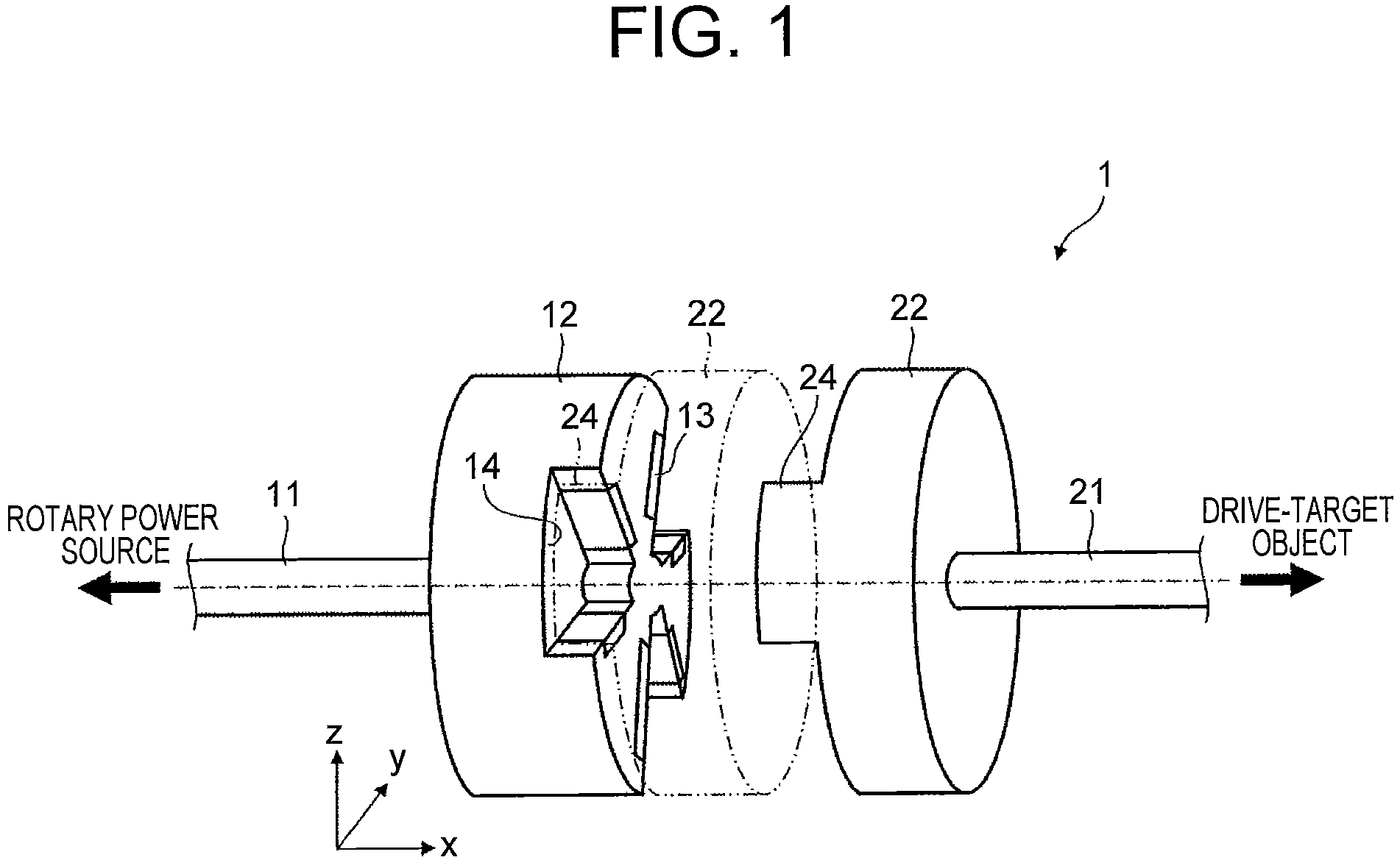
- FIG. 1 is a perspective view of the rotational power transmission mechanism according to the first embodiment.
- the rotational power transmission mechanism 1 includes an input shaft 11, an input-side rotary member 12, an output shaft 21, and an output-side rotary member 22.
- Right-handed xyz coordinates shown in the drawings are illustrated for convenience of explanation regarding a positional relation among configuration elements. For example, a plus direction of the z-axis represents a vertically upward direction, and an x-y plane represents a horizontal plane.
- the input-side rotary member (a first rotary member) 12 in a disk shape is fixed to a tip end of the input shaft 11 located on the output shaft 21 side, the input shaft 11 being coupled to a rotary power source such as an electric motor, a hydraulic motor, and an air motor.
- the output-side rotary member 22 in a disk shape is fixed to a tip end of the output shaft 21 located on the input shaft 11 side, the output shaft 21 being coupled to a drive-target object.
- the input-side rotary member 12 and the output-side rotary member (a second rotary member) 22 are disposed to face each other.
- multiple recessed portions 14 formed around a rotational axis are arranged along a circumferential direction with equal intervals.
- three recessed portions 14 are formed on the input-side rotary member 12.
- multiple projected portions 24 formed around a rotational axis are arranged along the circumferential direction with equal intervals.
- three projected portions 24 are formed on the output-side rotary member 22.
- the number of the recessed portions 14 formed on the input-side rotary member 12 and the number of the projected portions 24 formed on the output-side rotary member 22 may be one, respectively. However, as described later, in order to maintain the non-contact state by repellent force of permanent magnets, pluralities of recessed portions 14 and projected portion 24 may be provided. As described above, the multiple recessed portions 14 and the multiple projected portions 24 may be arranged with equal intervals, respectively.
- FIG. 2 and FIG. 3 are sectional views, each showing a positional relation between the input-side rotary member 12 and the output-side rotary member 22.
- FIG. 2 shows a non-contact state between the input-side rotary member 12 and the output-side rotary member 22.
- FIG. 3 shows a contact state between the input-side rotary member 12 and the output-side rotary member 22.
- each of the recessed portions 14 is formed in a flabellate shape expanding from the rotational axis toward the outer circumferential surface of the input-side rotary member 12.
- each of the projected portions 24 is formed in a flabellate shape from the rotational axis toward the outer circumferential surface of the output-side rotary member 22.
- each projected portion 24 to be inserted into each corresponding recessed portion 14 has a smaller width in the circumferential direction than that of this recessed portion 14.
- each projected portion 24 is relatively rotatable in the circumferential direction in each corresponding recessed portion 14. That is, the input-side rotary member 12 and the output-side rotary member 22 can be relatively rotatable in the circumferential direction.
- each recessed portion 14 to come into contact with each corresponding projected portion 24 is provided with permanent magnets 13 such that each recessed portion 14 and each corresponding projected portion 24 repel each other.
- a pair of contact surfaces of each projected portion 24 to come into contact with each corresponding recessed portion 14 is provided with permanent magnets 23 such that each recessed portion 14 and each corresponding projected portion 24 repel each other.
- the respective contact surfaces of each permanent magnet 13 and each corresponding permanent magnet 23 that come into contact with each other have the same polarity.
- Reference numerals S and N indicated inside of each permanent magnet 13 and each permanent magnet 23 in Figs. 2 and 3 indicate polarities in the respective contact surfaces of the permanent magnet 13 and the permanent magnet 23.
- each projected portion 24 the permanent magnets 23 in the pair of contact surfaces are arranged to be different in polarity from each other.
- the permanent magnets 13 in the pair of contact surfaces adjacent to each corresponding projected portion 24 are arranged to be different in polarity from each other. Hence, it is possible to align magnetic flux lines of the two permanent magnets 13 so as to boost repellent force between each permanent magnet 13 and each corresponding permanent magnet 23.
- the rotational power transmission mechanism 1 when the rotational torque is relatively small, the rotational power can be transmitted from the input-side rotary member 12 to the output-side rotary member 22 in a non-contact state; and when the rotational torque is relatively large, the input-side rotary member 12 and the output-side rotary member 22 come into contact with each other, to thereby suppress slippage therebetween.
- FIG. 4 is a perspective sectional view of a heat treatment furnace to which the rotational power transmission mechanism according to the first embodiment is applied.
- the rotational power of a motor 30 coupled to the input shaft 11 is transmitted from the input-side rotary member 12 to the output-side rotary member 22 so as to rotate a fan 40 fixed to the tip end of the output shaft 21.
- the fan 40 is disposed inside a furnace body 50. By rotationally driving the fan 40, it is possible to agitate the air inside the furnace body 50 so as to uniform the temperature inside the furnace body 50.
- the drive shaft of the fan 40 is configured as a single shaft without being divided into the input shaft 11 and the output shaft 21, heat inside the furnace body 50 is released through this drive shaft.
- the drive shaft of the fan 40 is divided into the input shaft 11 and the output shaft 21. It is possible to transmit the rotational power from the input-side rotary member 12 fixed to the tip end of the input shaft 11 to the output-side rotary member 22 fixed to the tip end of the output shaft 21 in a non-contact state. Hence, heat transfer from the furnace body 50 via the output shaft 21 can be blocked between the output-side rotary member 22 and the input-side rotary member 12. In this manner, by using the rotational power transmission mechanism according to the first embodiment, it is possible to provide a heat treatment furnace excellent in thermal insulation.
- the rotational power transmission mechanism when the rotational torque is relatively small, the rotational power can be transmitted from the input-side rotary member 12 to the output-side rotary member 22 in a non-contact state; and when the rotational power is relatively large, the input-side rotary member 12 and the output-side rotary member 22 can come into contact with each other, to thereby suppress slippage therebetween.
- the present invention is not limited to the above embodiments, and may appropriately be changed without departing from the scope of the invention.
- the input-side rotary member 12 and the output-side rotary member 22 may have respective shapes that oppose each other.
Landscapes
- Engineering & Computer Science (AREA)
- General Engineering & Computer Science (AREA)
- Mechanical Engineering (AREA)
- Power Engineering (AREA)
- Chemical & Material Sciences (AREA)
- Physics & Mathematics (AREA)
- Thermal Sciences (AREA)
- Crystallography & Structural Chemistry (AREA)
- Materials Engineering (AREA)
- Metallurgy (AREA)
- Organic Chemistry (AREA)
- Dynamo-Electric Clutches, Dynamo-Electric Brakes (AREA)
Abstract
A rotational power transmission mechanism (1) includes: an input shaft (11) and an output shaft (21) that are apart from each other; a first rotary member (12) fixed to a tip end of the input shaft (11) on an output shaft (21) side of the input shaft (11); and a second rotary member (22) fixed to a tip end of the output shaft (21) on an input shaft (11) side of the output shaft (21) so as to face the first rotary member. Into recessed portions (14), projected portions (24) are inserted, permanent magnets (13, 23) are respectively provided on a pair of contact surfaces of each recessed portion (14) and on a pair of contact surfaces of each projected portion (24) in such a manner that the recessed portion (14) and the projected portion (24) repel each other at the respective pairs of contact surfaces where the recessed portion (14) and the projected portion (24) come into contact with each other.
Description
- The present invention relates to a rotational power transmission mechanism and a heat treatment furnace, in particular to a rotational power transmission mechanism and a heat treatment furnace capable of transmitting rotational power from an input shaft to an output shaft apart from the input shaft in a non-contact state.
- Japanese Patent Application publication No.
57-134066 - In the rotational power transmission mechanism disclosed in
JP 57-134066 A - The present invention provides a rotational power transmission mechanism and a heat treatment furnace capable of transmitting rotational power in a non-contact state as well as suppressing slippage.
- A rotational power transmission mechanism according to one first aspect of the present invention includes: an input shaft and an output shaft that are apart from each other; a first rotary member fixed to a tip end of the input shaft on an output shaft side of the input shaft; and a second rotary member fixed to a tip end of the output shaft on an input shaft side of the output shaft so as to face the first rotary member, wherein into a recessed portion formed around a rotational axis of one of the first rotary member and the second rotary member, a projected portion formed around a rotational axis of the other of the first rotary member and the second rotary member is inserted such that the first rotary member and the second rotary member are coupled to each other in a relatively rotatable manner, and permanent magnets are respectively provided on a pair of contact surfaces of the recessed portion and on a pair of contact surfaces of the projected portion in such a manner that the recessed portion and the projected portion repel each other at the respective pairs of contact surfaces where the recessed portion and the projected portion come into contact with each other through relative rotation between the first rotary member and the second rotary member.
- In the rotational power transmission mechanism according to one aspect of the present invention, into the recessed portion formed around the rotational axis of one of the first rotary member and the second rotary member, the projected portion formed around the rotational axis of the other of the first rotary member and the second rotary member is inserted such that the first rotary member and the second rotary member are coupled to each other in a relatively rotatable manner, the permanent magnets are provided on the pair of contact surfaces of the recessed portion and on the pair of contact surfaces of the projected portion in such a manner that the recessed portion and the projected portion repel each other at the respective pairs of contact surfaces where the recessed portion and the projected portion come into contact with each other through relative rotation between the first rotary member and the second rotary member. With such a configuration, when rotational torque is relatively small, the rotational power can be transmitted from the first rotary member to the second rotary member in a non-contact state by repellent force of the permanent magnets. On the other hand, when the rotational power is relatively large, since the rotational torque overcomes the repellent force of the permanent magnets to come into contact with each other, the slippage is suppressed, and the rotational power can be transmitted directly from the first rotary member to the second rotary member. That is, the rotational power can be transmitted in a non-contact state, while the slippage can be suppressed.
- In the projected portion, the permanent magnets in the pair of contact surfaces have different polarities from each other. With such a configuration, it is possible to align magnetic flux lines of the pair of permanent magnets provided on the projected portion so as to boost repellent force against the permanent magnets provided on the recessed portion, to thereby easily maintain the non-contact state between the first rotary member and the second rotary member.
- A plurality of recessed portions may be formed with intervals along a circumferential direction of the first rotary member, and a plurality of projected portions may be formed with intervals along a circumferential direction of the second rotary member. With such a configuration, it is possible to boost the repellent force of the permanent magnets, to thereby easily maintain the non-contact state between the first rotary member and the second rotary member.
- A heat treatment furnace according to one aspect of the present invention includes: the above rotational power transmission mechanism; a motor coupled to the input shaft of the rotational power transmission mechanism; a fan fixed to a tip end of the output shaft of the rotational power transmission mechanism; and a furnace body, wherein the fan is disposed inside the furnace body.
- According to the present invention, it is possible to provide a rotational power transmission mechanism and a heat treatment furnace capable of transmitting the rotational power in a non-contact state, and suppressing the slippage.
- Features, advantages, and technical and industrial significance of exemplary embodiments of the invention will be described below with reference to the accompanying drawings, in which like numerals denote like elements, and wherein:
-
FIG. 1 is a perspective view of a rotational power transmission mechanism according to a first embodiment; -
FIG. 2 is a cross-sectional view showing a positional relation between an input-side rotary member 12 and an output-side rotary member 22; -
FIG. 3 is a cross-sectional view showing the positional relation between the input-siderotary member 12 and the output-side rotary member 22; and -
FIG. 4 is a perspective sectional view of a heat treatment furnace to which the rotational power transmission mechanism according to the first embodiment is applied. - Hereinafter, specific embodiments to which the present invention is applied will be described with reference to drawings. However, the present invention is not limited to the following embodiments. In addition, for the sake of clarifying the description, the following description and drawings are appropriately simplified.
- (First embodiment) First, with reference to
FIG. 1 , a rotational power transmission mechanism according to the first embodiment will be described.FIG. 1 is a perspective view of the rotational power transmission mechanism according to the first embodiment. As shown inFIG. 1 , the rotationalpower transmission mechanism 1 includes aninput shaft 11, an input-side rotary member 12, anoutput shaft 21, and an output-side rotary member 22. Right-handed xyz coordinates shown in the drawings are illustrated for convenience of explanation regarding a positional relation among configuration elements. For example, a plus direction of the z-axis represents a vertically upward direction, and an x-y plane represents a horizontal plane. - As shown in
FIG. 1 , the input-side rotary member (a first rotary member) 12 in a disk shape is fixed to a tip end of theinput shaft 11 located on theoutput shaft 21 side, theinput shaft 11 being coupled to a rotary power source such as an electric motor, a hydraulic motor, and an air motor. On the other hand, the output-side rotary member 22 in a disk shape is fixed to a tip end of theoutput shaft 21 located on theinput shaft 11 side, theoutput shaft 21 being coupled to a drive-target object. The input-side rotary member 12 and the output-side rotary member (a second rotary member) 22 are disposed to face each other. - On a face of the input-
side rotary member 12, the face facing the output-siderotary member 22, multiple recessedportions 14 formed around a rotational axis are arranged along a circumferential direction with equal intervals. In an example ofFIG. 1 , three recessedportions 14 are formed on the input-side rotary member 12. On the other hand, on a face of the output-siderotary member 22, the face facing the input-siderotary member 12, multiple projectedportions 24 formed around a rotational axis are arranged along the circumferential direction with equal intervals. In the example ofFIG. 1 , three projectedportions 24 are formed on the output-siderotary member 22. - The number of the recessed
portions 14 formed on the input-siderotary member 12 and the number of the projectedportions 24 formed on the output-siderotary member 22 may be one, respectively. However, as described later, in order to maintain the non-contact state by repellent force of permanent magnets, pluralities of recessedportions 14 and projectedportion 24 may be provided. As described above, the multiple recessedportions 14 and the multiple projectedportions 24 may be arranged with equal intervals, respectively. - As indicated by two-dot chain lines in
FIG. 1 , the projectedportions 24 of the output-siderotary member 22 are inserted into the corresponding recessedportions 14 of the input-side rotary member 12 so that the input-side rotary member 12 is coupled to the output-siderotary member 22 in a relatively rotatable manner. Here,FIG. 2 andFIG. 3 are sectional views, each showing a positional relation between the input-siderotary member 12 and the output-side rotary member 22.FIG. 2 shows a non-contact state between the input-side rotary member 12 and the output-side rotary member 22.FIG. 3 shows a contact state between the input-side rotary member 12 and the output-side rotary member 22. - As shown in
FIG. 1 andFIG. 2 , each of therecessed portions 14 is formed in a flabellate shape expanding from the rotational axis toward the outer circumferential surface of the input-siderotary member 12. On the other hand, as shown inFIG. 2 , each of the projectedportions 24 is formed in a flabellate shape from the rotational axis toward the outer circumferential surface of the output-siderotary member 22. Here, each projectedportion 24 to be inserted into each correspondingrecessed portion 14 has a smaller width in the circumferential direction than that of thisrecessed portion 14. Hence, as shown inFIG. 2 andFIG. 3 , each projectedportion 24 is relatively rotatable in the circumferential direction in each correspondingrecessed portion 14. That is, the input-side rotary member 12 and the output-side rotary member 22 can be relatively rotatable in the circumferential direction. - As shown in
FIG. 1 to FIG. 3 , a pair of contact surfaces of eachrecessed portion 14 to come into contact with each corresponding projectedportion 24 is provided withpermanent magnets 13 such that eachrecessed portion 14 and each corresponding projectedportion 24 repel each other. Similarly, a pair of contact surfaces of each projectedportion 24 to come into contact with each correspondingrecessed portion 14 is provided withpermanent magnets 23 such that eachrecessed portion 14 and each corresponding projectedportion 24 repel each other. This means that the respective contact surfaces of eachpermanent magnet 13 and each correspondingpermanent magnet 23 that come into contact with each other have the same polarity. Reference numerals S and N indicated inside of eachpermanent magnet 13 and eachpermanent magnet 23 inFigs. 2 and3 indicate polarities in the respective contact surfaces of thepermanent magnet 13 and thepermanent magnet 23. - As shown in
FIG. 2 andFIG. 3 , in each projectedportion 24, thepermanent magnets 23 in the pair of contact surfaces are arranged to be different in polarity from each other. In such a configuration, in each projectedportion 24, it is possible to align magnetic flux lines of the twopermanent magnets 23 so as to boost repellent force between eachpermanent magnet 13 and each correspondingpermanent magnet 23. In addition, in eachrecessed portion 14 adjacent to each corresponding projectedportion 24, thepermanent magnets 13 in the pair of contact surfaces adjacent to each corresponding projectedportion 24 are arranged to be different in polarity from each other. Hence, it is possible to align magnetic flux lines of the twopermanent magnets 13 so as to boost repellent force between eachpermanent magnet 13 and each correspondingpermanent magnet 23. - With the above configuration, when the rotational torque is relatively small, as shown in
FIG. 2 , with the repellent force between thepermanent magnets 13 and thepermanent magnets 23, the rotational power can be transmitted from the input-side rotary member 12 to the output-siderotary member 22 in a non-contact state. On the other hand, when the rotational torque is relatively large, as shown inFIG. 3 , the rotational torque overcomes the repellent force between thepermanent magnets 13 and thepermanent magnets 23, so that the recessedportions 14 and the projectedportions 24 come into contact with each other. Hence, it is possible to directly transmit the rotational power from the input-side rotary member 12 to the output-side rotary member 22. - In this manner, in the rotational
power transmission mechanism 1 according to the present embodiment, when the rotational torque is relatively small, the rotational power can be transmitted from the input-side rotary member 12 to the output-side rotary member 22 in a non-contact state; and when the rotational torque is relatively large, the input-side rotary member 12 and the output-side rotary member 22 come into contact with each other, to thereby suppress slippage therebetween. -
FIG. 4 is a perspective sectional view of a heat treatment furnace to which the rotational power transmission mechanism according to the first embodiment is applied. The rotational power of amotor 30 coupled to theinput shaft 11 is transmitted from the input-side rotary member 12 to the output-side rotary member 22 so as to rotate afan 40 fixed to the tip end of theoutput shaft 21. Thefan 40 is disposed inside afurnace body 50. By rotationally driving thefan 40, it is possible to agitate the air inside thefurnace body 50 so as to uniform the temperature inside thefurnace body 50. - Here, if the drive shaft of the
fan 40 is configured as a single shaft without being divided into theinput shaft 11 and theoutput shaft 21, heat inside thefurnace body 50 is released through this drive shaft. To the contrary, in the heat treatment furnace to which the rotational power transmission mechanism according to the first embodiment is applied, the drive shaft of thefan 40 is divided into theinput shaft 11 and theoutput shaft 21. It is possible to transmit the rotational power from the input-side rotary member 12 fixed to the tip end of theinput shaft 11 to the output-side rotary member 22 fixed to the tip end of theoutput shaft 21 in a non-contact state. Hence, heat transfer from thefurnace body 50 via theoutput shaft 21 can be blocked between the output-side rotary member 22 and the input-side rotary member 12. In this manner, by using the rotational power transmission mechanism according to the first embodiment, it is possible to provide a heat treatment furnace excellent in thermal insulation. - Furthermore, in the heat treatment furnace to which the rotational power transmission mechanism according to the first embodiment is applied, as aforementioned, when the rotational torque is relatively small, the rotational power can be transmitted from the input-
side rotary member 12 to the output-side rotary member 22 in a non-contact state; and when the rotational power is relatively large, the input-side rotary member 12 and the output-side rotary member 22 can come into contact with each other, to thereby suppress slippage therebetween. - The present invention is not limited to the above embodiments, and may appropriately be changed without departing from the scope of the invention. For example, the input-
side rotary member 12 and the output-side rotary member 22 may have respective shapes that oppose each other.
Claims (4)
- A rotational power transmission mechanism (1) comprising:an input shaft (11) and an output shaft (21) that are apart from each other;a first rotary member (12) fixed to a tip end of the input shaft (11) on an output shaft (21) side of the input shaft (11); anda second rotary member (22) fixed to a tip end of the output shaft (21) on an input shaft (11) side of the output shaft (21) so as to face the first rotary member (12),whereininto a recessed portion (14) formed around a rotational axis of one of the first rotary member (12) and the second rotary member (22), a projected portion (24) formed around a rotational axis of the other of the first rotary member (12) and the second rotary member (22) is inserted such that the first rotary member (12) and the second rotary member (22) are coupled to each other in a relatively rotatable manner,
andpermanent magnets (13, 23) are respectively provided on a pair of contact surfaces of the recessed portion (14) and on a pair of contact surfaces of the projected portion (24) in such a manner that the recessed portion (14) and the projected portion (24) repel each other at the respective pairs of contact surfaces where the recessed portion (14) and the projected portion (24) come into contact with each other through relative rotation between the first rotary member (12) and the second rotary member (22). - The rotational power transmission mechanism (1) according to claim 1, wherein
in the projected portion (24), the permanent magnets (23) in the pair of contact surfaces have different polarities from each other. - The rotational power transmission mechanism (1) according to claim 1 or 2, wherein
a plurality of recessed portions (14) are formed with intervals along a circumferential direction of the first rotary member (12),
and
a plurality of projected portions (24) are formed with intervals along a circumferential direction of the second rotary member (22). - A heat treatment furnace comprising:the rotational power transmission mechanism (1) according to any one of claims 1 to 3;a motor (30) coupled to the input shaft (11) of the rotational power transmission mechanism (1);a fan (40) fixed to a tip end of the output shaft (21) of the rotational power transmission mechanism (1); anda furnace body (50),whereinthe fan (40) is disposed inside the furnace body (50).
Applications Claiming Priority (1)
| Application Number | Priority Date | Filing Date | Title |
|---|---|---|---|
| JP2016221895A JP2018080723A (en) | 2016-11-14 | 2016-11-14 | Rotation power transmission mechanism |
Publications (1)
| Publication Number | Publication Date |
|---|---|
| EP3330558A1 true EP3330558A1 (en) | 2018-06-06 |
Family
ID=60387819
Family Applications (1)
| Application Number | Title | Priority Date | Filing Date |
|---|---|---|---|
| EP17199013.8A Withdrawn EP3330558A1 (en) | 2016-11-14 | 2017-10-27 | Rotational power transmission mechanism and heat treatment furnace |
Country Status (4)
| Country | Link |
|---|---|
| US (1) | US20180138796A1 (en) |
| EP (1) | EP3330558A1 (en) |
| JP (1) | JP2018080723A (en) |
| CN (1) | CN108071778A (en) |
Cited By (1)
| Publication number | Priority date | Publication date | Assignee | Title |
|---|---|---|---|---|
| RU2765517C2 (en) * | 2018-07-30 | 2022-01-31 | Инзим Наильевич Набиуллин | Motion transfer mechanism with magnetic coupling |
Families Citing this family (5)
| Publication number | Priority date | Publication date | Assignee | Title |
|---|---|---|---|---|
| EP3118977B1 (en) * | 2015-07-13 | 2019-06-26 | iLOQ Oy | Electromechanical lock utilizing magnetic field forces |
| EP3736084B1 (en) * | 2019-05-07 | 2021-03-10 | Guido Valentini | Hand-held power tool for sanding or polishing a workpiece |
| CN111664201B (en) * | 2020-04-24 | 2021-05-18 | 清华大学 | Magnetic coupling and power mechanism with the magnetic coupling |
| WO2023048929A2 (en) * | 2021-09-22 | 2023-03-30 | Waters Technologies Corporation | Rotary coupling with magnetic preload |
| CN115178387B (en) * | 2022-08-10 | 2023-06-20 | 东莞市华汇精密机械有限公司 | High-speed centrifugal atomizer |
Citations (5)
| Publication number | Priority date | Publication date | Assignee | Title |
|---|---|---|---|---|
| SU872838A1 (en) * | 1979-12-03 | 1981-10-15 | Заивигель | Coupling |
| JPS57134066A (en) | 1981-02-09 | 1982-08-19 | Shintaro Oshima | Transmission device |
| JPH10336997A (en) * | 1998-03-17 | 1998-12-18 | Shikoku Sogo Kenkyusho:Kk | Rotation transmitting mechanism |
| US20080217373A1 (en) * | 2007-03-05 | 2008-09-11 | Piercarlo Boffelli | Magnetic Repulsion Coupling for Transmission of a Rotational Movement from a Driving Member to a Driven Member |
| US20150108863A1 (en) * | 2013-10-23 | 2015-04-23 | Emergy Corporation | Non-contact power transmission apparatus |
Family Cites Families (7)
| Publication number | Priority date | Publication date | Assignee | Title |
|---|---|---|---|---|
| FR2499647B1 (en) * | 1981-02-06 | 1989-03-03 | Nova Scotia Res Found | IMPROVEMENTS ON HERMETIC MAGNETIC COUPLINGS |
| JPH07208876A (en) * | 1994-01-13 | 1995-08-11 | Daido Steel Co Ltd | Vacuum furnace |
| JP2001343026A (en) * | 2000-03-29 | 2001-12-14 | Toyota Industries Corp | Power transmission mechanism |
| JP2009121676A (en) * | 2007-10-26 | 2009-06-04 | Denso Corp | Power transmission device |
| JP5281464B2 (en) * | 2009-04-10 | 2013-09-04 | 株式会社プロスパイン | Clutch device |
| JP5447418B2 (en) * | 2011-03-28 | 2014-03-19 | 株式会社豊田自動織機 | Rotating electric machine permanent magnet embedded rotor and rotating electric machine |
| US9441681B2 (en) * | 2012-04-18 | 2016-09-13 | Litens Automotive Partnership | Power transmitting device with overrunning decoupler |
-
2016
- 2016-11-14 JP JP2016221895A patent/JP2018080723A/en active Pending
-
2017
- 2017-10-26 US US15/794,052 patent/US20180138796A1/en not_active Abandoned
- 2017-10-27 EP EP17199013.8A patent/EP3330558A1/en not_active Withdrawn
- 2017-11-01 CN CN201711055895.9A patent/CN108071778A/en active Pending
Patent Citations (5)
| Publication number | Priority date | Publication date | Assignee | Title |
|---|---|---|---|---|
| SU872838A1 (en) * | 1979-12-03 | 1981-10-15 | Заивигель | Coupling |
| JPS57134066A (en) | 1981-02-09 | 1982-08-19 | Shintaro Oshima | Transmission device |
| JPH10336997A (en) * | 1998-03-17 | 1998-12-18 | Shikoku Sogo Kenkyusho:Kk | Rotation transmitting mechanism |
| US20080217373A1 (en) * | 2007-03-05 | 2008-09-11 | Piercarlo Boffelli | Magnetic Repulsion Coupling for Transmission of a Rotational Movement from a Driving Member to a Driven Member |
| US20150108863A1 (en) * | 2013-10-23 | 2015-04-23 | Emergy Corporation | Non-contact power transmission apparatus |
Cited By (1)
| Publication number | Priority date | Publication date | Assignee | Title |
|---|---|---|---|---|
| RU2765517C2 (en) * | 2018-07-30 | 2022-01-31 | Инзим Наильевич Набиуллин | Motion transfer mechanism with magnetic coupling |
Also Published As
| Publication number | Publication date |
|---|---|
| CN108071778A (en) | 2018-05-25 |
| US20180138796A1 (en) | 2018-05-17 |
| JP2018080723A (en) | 2018-05-24 |
Similar Documents
| Publication | Publication Date | Title |
|---|---|---|
| EP3330558A1 (en) | Rotational power transmission mechanism and heat treatment furnace | |
| CA2908450C (en) | Electromagnetic actuator for a bi-directional clutch | |
| CN113305786B (en) | Power Tools | |
| JP2015169225A (en) | Joint device and motor | |
| KR101059268B1 (en) | Magnetic coupling for conveyor | |
| CN111148603B (en) | Electric tool | |
| KR102587789B1 (en) | A magnetic coupling | |
| JP2013234699A (en) | Magnetic coupling device | |
| US12388341B2 (en) | Systems and methods for magnetic rotational coupling devices | |
| KR20130084485A (en) | Hollow shaft type motor | |
| JP5032777B2 (en) | Torque transmission device | |
| JP6761414B2 (en) | Rotational coupling device for bimodal selective output | |
| JP2012197805A (en) | Magnetic coupling device | |
| JP6361695B2 (en) | Drive transmission device | |
| JP2012031915A (en) | Torque transmission device | |
| JP2012057790A (en) | Surface facing type magnetic coupling device | |
| JP5991417B2 (en) | Rotating machine | |
| JP2008051264A (en) | Magnetic torque transmission device | |
| JP2015169247A (en) | rotation transmitting device | |
| JP2010031910A (en) | Outside joint member of constant velocity universal joint and constant velocity universal joint | |
| EP3113342A1 (en) | Linear rotary mechanism | |
| KR101716424B1 (en) | Spherical motor using ultrasonic motor | |
| JP2018123960A (en) | Magnetic gear device | |
| KR20200082849A (en) | Clutch unit and motor having the same | |
| KR101673467B1 (en) | Coupler and apparatus for generating torque comprising the same |
Legal Events
| Date | Code | Title | Description |
|---|---|---|---|
| PUAI | Public reference made under article 153(3) epc to a published international application that has entered the european phase |
Free format text: ORIGINAL CODE: 0009012 |
|
| STAA | Information on the status of an ep patent application or granted ep patent |
Free format text: STATUS: REQUEST FOR EXAMINATION WAS MADE |
|
| 17P | Request for examination filed |
Effective date: 20171027 |
|
| AK | Designated contracting states |
Kind code of ref document: A1 Designated state(s): AL AT BE BG CH CY CZ DE DK EE ES FI FR GB GR HR HU IE IS IT LI LT LU LV MC MK MT NL NO PL PT RO RS SE SI SK SM TR |
|
| AX | Request for extension of the european patent |
Extension state: BA ME |
|
| STAA | Information on the status of an ep patent application or granted ep patent |
Free format text: STATUS: THE APPLICATION HAS BEEN WITHDRAWN |
|
| 18W | Application withdrawn |
Effective date: 20190701 |