EP3330511B1 - Engine temperature regulating device - Google Patents
Engine temperature regulating device Download PDFInfo
- Publication number
- EP3330511B1 EP3330511B1 EP16202296.6A EP16202296A EP3330511B1 EP 3330511 B1 EP3330511 B1 EP 3330511B1 EP 16202296 A EP16202296 A EP 16202296A EP 3330511 B1 EP3330511 B1 EP 3330511B1
- Authority
- EP
- European Patent Office
- Prior art keywords
- casing
- engine
- power source
- air intake
- surrounding member
- Prior art date
- Legal status (The legal status is an assumption and is not a legal conclusion. Google has not performed a legal analysis and makes no representation as to the accuracy of the status listed.)
- Active
Links
Images




Classifications
-
- F—MECHANICAL ENGINEERING; LIGHTING; HEATING; WEAPONS; BLASTING
- F01—MACHINES OR ENGINES IN GENERAL; ENGINE PLANTS IN GENERAL; STEAM ENGINES
- F01P—COOLING OF MACHINES OR ENGINES IN GENERAL; COOLING OF INTERNAL-COMBUSTION ENGINES
- F01P7/00—Controlling of coolant flow
- F01P7/02—Controlling of coolant flow the coolant being cooling-air
- F01P7/10—Controlling of coolant flow the coolant being cooling-air by throttling amount of air flowing through liquid-to-air heat exchangers
- F01P7/12—Controlling of coolant flow the coolant being cooling-air by throttling amount of air flowing through liquid-to-air heat exchangers by thermostatic control
-
- B—PERFORMING OPERATIONS; TRANSPORTING
- B60—VEHICLES IN GENERAL
- B60K—ARRANGEMENT OR MOUNTING OF PROPULSION UNITS OR OF TRANSMISSIONS IN VEHICLES; ARRANGEMENT OR MOUNTING OF PLURAL DIVERSE PRIME-MOVERS IN VEHICLES; AUXILIARY DRIVES FOR VEHICLES; INSTRUMENTATION OR DASHBOARDS FOR VEHICLES; ARRANGEMENTS IN CONNECTION WITH COOLING, AIR INTAKE, GAS EXHAUST OR FUEL SUPPLY OF PROPULSION UNITS IN VEHICLES
- B60K11/00—Arrangement in connection with cooling of propulsion units
- B60K11/06—Arrangement in connection with cooling of propulsion units with air cooling
-
- B—PERFORMING OPERATIONS; TRANSPORTING
- B60—VEHICLES IN GENERAL
- B60K—ARRANGEMENT OR MOUNTING OF PROPULSION UNITS OR OF TRANSMISSIONS IN VEHICLES; ARRANGEMENT OR MOUNTING OF PLURAL DIVERSE PRIME-MOVERS IN VEHICLES; AUXILIARY DRIVES FOR VEHICLES; INSTRUMENTATION OR DASHBOARDS FOR VEHICLES; ARRANGEMENTS IN CONNECTION WITH COOLING, AIR INTAKE, GAS EXHAUST OR FUEL SUPPLY OF PROPULSION UNITS IN VEHICLES
- B60K11/00—Arrangement in connection with cooling of propulsion units
- B60K11/08—Air inlets for cooling; Shutters or blinds therefor
- B60K11/085—Air inlets for cooling; Shutters or blinds therefor with adjustable shutters or blinds
-
- B—PERFORMING OPERATIONS; TRANSPORTING
- B60—VEHICLES IN GENERAL
- B60Y—INDEXING SCHEME RELATING TO ASPECTS CROSS-CUTTING VEHICLE TECHNOLOGY
- B60Y2200/00—Type of vehicle
- B60Y2200/10—Road Vehicles
- B60Y2200/12—Motorcycles, Trikes; Quads; Scooters
-
- Y—GENERAL TAGGING OF NEW TECHNOLOGICAL DEVELOPMENTS; GENERAL TAGGING OF CROSS-SECTIONAL TECHNOLOGIES SPANNING OVER SEVERAL SECTIONS OF THE IPC; TECHNICAL SUBJECTS COVERED BY FORMER USPC CROSS-REFERENCE ART COLLECTIONS [XRACs] AND DIGESTS
- Y02—TECHNOLOGIES OR APPLICATIONS FOR MITIGATION OR ADAPTATION AGAINST CLIMATE CHANGE
- Y02T—CLIMATE CHANGE MITIGATION TECHNOLOGIES RELATED TO TRANSPORTATION
- Y02T10/00—Road transport of goods or passengers
- Y02T10/80—Technologies aiming to reduce greenhouse gasses emissions common to all road transportation technologies
- Y02T10/88—Optimized components or subsystems, e.g. lighting, actively controlled glasses
Definitions
- the present invention relates to a temperature regulating device, in particular to the temperature regulating device installed to a casing with a cooled air inlet of an engine, and capable of adjusting an air intake hole to a smooth or obscured state according to a temperature change at the starting stage of the engine.
- a conventional compulsory cooling device of a motorcycle engine directly drives a cooling fan during the operation of the engine to suck surrounding cold air from the cooling fan into a wind hood, and the cold air in the wind hook cools the engine.
- the cooling fan will be rotated accordingly.
- the cooling fan is stopped synchronously. Since a fan cover is covered and mounted onto the cooling fan for preventing foreign substances from entering into the fan cover, and the fan cover usually comes with an air intake hole with a fixed size.
- the cooling fan sucks a large quantity of cold air from the air intake hole of the fan cover.
- document DE 10 2013 016509 A1 discloses an air quantity control device for a motor vehicle radiator installed in a casing with a cooling air inlet.
- R.O.C. Pat. No. 1421405 discloses a "Motorcycle engine cooling device" having a temperature switch connected to a cooling fan and installed in a cylinder head of an engine or an oil tank. When the temperature of the cylinder head of the engine or the oil tank is greater than or equal to a predetermined value, the temperature switch will be electrically conducted to turn on the cooling fan, and if the temperature of the cylinder head of the engine or the oil tank is smaller than a predetermined value, the temperature switch will not be electrically conducted, and the cooling fan will be turned off.
- U.S. Pat. No. 6142108 discloses a "Temperature control system for use with an enclosure which houses an internal combustion engine" having a plurality of adjoining walls of the enclosure of the temperature control system, and an inlet louver assembly and an outlet louver assembly of an actuator are coupled to the walls.
- a temperature sensor senses a temperature signal and outputs the temperature signal to an electrical processing circuit
- the electrical processing circuit controls the actuator to drive the outlet louvers to move.
- the fan structure requires an inlet louver assembly and outlet louver assembly to be installed at the front and rear ends of the fan structure respectively.
- the drawback of such patent includes requiring too many components and too complicated structure.
- the conventional compulsory cooling device of a motorcycle has the drawbacks of causing a long warm-up process, increasing the fuel consumption, and polluting the environment, therefore, it is a primary objective of the present invention to control the timing of the cold air entering into the cooled air inlet by the adjustable fan cover module, so as to prevent a large quantity of cold air from affecting the engine warm-up time and achieve the effects of lowering the fuel consumption and reducing waste gas discharge.
- the present invention provides an engine temperature regulating device installed in a casing with a cooled air inlet, comprising: a power source; a link rod module, connected to the power source; a control module, for detecting a temperature for starting the engine to obtain a temperature signal, and controlling the drive of the power source when the temperature signal is lower than a predetermined value or controlling and turning off the power source when the temperature signal achieves the predetermined value; and a fan cover module, covered onto the cooled air inlet, and further comprising: a fixed casing, formed by mounting a first surrounding member around the fixed casing, and the first sidewall having a plurality of first air intake holes and a plurality of first shelter plates arranged alternately with one another, and disposed at a plurality of first ventilation holes of the first surrounding member, and at least one fixed block disposed around the external periphery of the first surrounding member and capable of locking the casing with the cooled air inlet; and a movable casing, formed by mounting a first surrounding member around the fixed casing
- the first air intake hole of the fixed casing is set to a smooth state when the engine is not started, and after the engine is started and if the engine temperature detected by the control module is lower than a predetermined value, then the power source will be driven to connect the power source to the link rod module, so that the movable casing of the link rod module will be rotated to cover the second shelter plate of the movable casing onto the first air intake hole of the fixed casing and drive the first air intake hole into the obscured state.
- external cold air cannot enters from the air intake hole into the engine cooled air inlet, and the amount of air in the wind hood is limited to accelerate the engine warm-up process.
- the power source will be turned off, so that the link rod module coupled to the movable casing will restores its initial position and let the first air intake hole of the fixed casing and the second air intake hole of the movable casing be superimposed and drive them into the smooth state. As a result, surrounding cold air is sucked into the air inlet continuously to assist the heat dissipation of the engine.
- the engine temperature regulating device 1 is installed to a casing with a cooled air inlet and comprises a power source 2, a link rod module 3, a control module 4 and a fan cover module 5.
- the link rod module 3 is connected to the power source 2, and the power source 2 is preferably stepper motor;
- the control module 4 is provided for detecting a temperature for starting the engine to obtain a temperature signal, and if the temperature signal is lower than a predetermined value, the power source 2 will be controlled and driven, or if the temperature signal reaches a predetermined value, the power source 2 will be controlled to turn off.
- the fan cover module 5 is covered onto the engine cooled air inlet and comprises a fixed casing 51 and a movable casing 52, wherein the fixed casing 51 is formed by mounting a first surrounding member 512 around a first sidewall 511, and the first sidewall 511 has a plurality of first air intake holes 5111 and a plurality of first shelter plates 5112 arranged alternately with one another, and the first surrounding member 512 has a plurality of first ventilation holes 5121, and at least one fixing block 5122 disposed at the external periphery of the first surrounding member 512 and capable of being secured to the casing with a cooled air inlet.
- the movable casing 52 is formed by mounting a second surrounding member 522 around a second sidewall 521, and the second sidewall 521 has a plurality of second air intake holes 5211 and a plurality of second shelter plates 5212 arranged alternately with one another and the second surrounding member 522 has a plurality of second ventilation holes 5221, and a positioning block 5222 disposed at the external periphery of the second surrounding member 522 and the link rod module 3 is coupled to the movable casing 52.
- the fixed casing 51 has an opening 513, a first bump 514 and a second bump 515 formed at the external periphery of the fixed casing 51
- the movable casing 52 has a peg 523 configured to be corresponsive to the opening 513, so that the peg 523 of the movable casing 52 is passed into the opening 513 of the fixed casing 51, and a fastener 53 is provided for securing the peg 523, and the movable casing 52 can be pivotally rotated in the fixed casing 51 by using the peg 523 as an axis, and the positioning block 5222 of the movable casing 52 are limited and rotated between the first bump 514 and second bump 515 of the fixed casing 51.
- the fan cover module 5 is covered onto a cooling fan 6 of the engine.
- the positioning block 5222 of the movable casing 52 abuts against the second bump 515 of the fixed casing 51, so that the first air intake hole 5111 of the fixed casing 51 and the second air intake hole 5211 of the movable casing 52 are superimposed and defaulted to a smooth state.
- the control module 4 detects an engine temperature immediately. If a detected temperature signal is lower than a predetermined value, the power source 2 will be controlled and driven to rotate the stepper motor to pull the link rod module 3 (as shown in FIG. 4 ), so that the positioning block 5222 linked with the link rod module 3 is moved to abut against the first bump 514, and the second shelter plate 5212 of the movable casing 52 is covered onto the first air intake hole 5111 of the fixed casing 51 to set the first air intake hole 5111 to an obscured state. Now, external cold air cannot be entered into the cooled air inlet of the engine from the first air intake hole 5111, sot that the air in the wind hood is limited to accelerate the engine warm-up process.
- the power source 2 will be controlled to turn off, so that the stepper motor stops operating to resume the link rod module 3 to its initial position (as shown in FIG. 5 ), and the positioning block 5222 linked with the link rod module 3 will be moved back to the position of the second bump 515 to superimpose the first air intake hole 5111 of the of the fixed casing 51 and the second air intake hole 5211 of the movable casing 52 to set them into a smooth state, and the surrounding cold air can be sucked into the air inlet continuously to assist the heat dissipation of the engine.
- first surrounding member 512 of the fixed casing 51 and the second surrounding member 522 of the movable casing 52 has a plurality of first ventilation holes 5121 and a second ventilation hole 5221 respectively (as shown in FIG. 2 ).
- first ventilation hole 5121 of the fixed casing 51 and the second ventilation hole 5221 of the movable casing 52 are not arranged alternately with one another, so as to form a hole 54 (as shown in FIG. 6 ) and prevent the air inlet of the engine from being closed completely to cause an overheat of the engine or an inconsistent heat dissipation.
- the engine temperature regulating device 1 of the present invention has the following effects:
- the device 1 of the present invention can adjust the movement of the movable casing 52 of the fan cover module 5 according to the engine operating temperature, so that when the engine is just started and situated at a cold engine stage temperature which is lower than the operating temperature, the first air intake hole 5111 of the fixed casing 51 is adjusted to the obscured state to stop cooled airflow to enter into the engine and reduce the time for increasing the engine temperature to its operating temperature, so as to achieve the effects of lowering the fuel consumption, reducing the waste gas discharge of the engine.
- the first air intake hole 5111 of the fixed casing 51 resumes its smooth state and lets cooled airflow enter into the engine to assist the heat dissipation.
- the first air intake hole 5111 and second air intake hole 5211 of the fan cover module 5 of the present invention are defaulted to the smooth state, and thus when the device 1 fails, the fan cover module 5 is in a closed state and the heat dissipation of the engine is affected.
- the first ventilation hole 5121 of the fixed casing 51 and the second ventilation hole 5221 of the movable casing 52 reserve a hole 54 when the first air intake hole 5111 is in the obscured state, so as to prevent overheat or inconsistent heat dissipation of the engine.
Landscapes
- Engineering & Computer Science (AREA)
- Chemical & Material Sciences (AREA)
- Combustion & Propulsion (AREA)
- Mechanical Engineering (AREA)
- Transportation (AREA)
- General Engineering & Computer Science (AREA)
- Structures Of Non-Positive Displacement Pumps (AREA)
Description
- The present invention relates to a temperature regulating device, in particular to the temperature regulating device installed to a casing with a cooled air inlet of an engine, and capable of adjusting an air intake hole to a smooth or obscured state according to a temperature change at the starting stage of the engine.
- In general, a conventional compulsory cooling device of a motorcycle engine directly drives a cooling fan during the operation of the engine to suck surrounding cold air from the cooling fan into a wind hood, and the cold air in the wind hook cools the engine. In other words, once the engine is started, the cooling fan will be rotated accordingly. Until the engine is stopped, the cooling fan is stopped synchronously. Since a fan cover is covered and mounted onto the cooling fan for preventing foreign substances from entering into the fan cover, and the fan cover usually comes with an air intake hole with a fixed size. When the engine is just started and still situated in a warm-up stage, the cooling fan sucks a large quantity of cold air from the air intake hole of the fan cover. As a result, it takes a longer time for the warm-up process, and the motorcycle is not ready for running in a short time. In addition, a too-long warm-up process not just incurs high fuel consumption only, but also produces waste gas and pollutes the environment.
- To overcome the aforementioned drawback, document
DE 10 2013 016509 A1 discloses an air quantity control device for a motor vehicle radiator installed in a casing with a cooling air inlet. Alternatively, R.O.C. Pat. No.1421405 - In addition,
U.S. Pat. No. 6142108 discloses a "Temperature control system for use with an enclosure which houses an internal combustion engine" having a plurality of adjoining walls of the enclosure of the temperature control system, and an inlet louver assembly and an outlet louver assembly of an actuator are coupled to the walls. When a temperature sensor senses a temperature signal and outputs the temperature signal to an electrical processing circuit, the electrical processing circuit controls the actuator to drive the outlet louvers to move. Although such patent can adjust the size of the louvers according to temperature, the fan structure requires an inlet louver assembly and outlet louver assembly to be installed at the front and rear ends of the fan structure respectively. Obviously, the drawback of such patent includes requiring too many components and too complicated structure. - In view of the aforementioned drawbacks, the inventor of the present invention based on years of experience in the related industry to conduct extensive research and experiment, and finally developed an engine temperature regulating device in accordance with the present invention to overcome the drawbacks of the prior art.
- Since the conventional compulsory cooling device of a motorcycle has the drawbacks of causing a long warm-up process, increasing the fuel consumption, and polluting the environment, therefore, it is a primary objective of the present invention to control the timing of the cold air entering into the cooled air inlet by the adjustable fan cover module, so as to prevent a large quantity of cold air from affecting the engine warm-up time and achieve the effects of lowering the fuel consumption and reducing waste gas discharge.
- To achieve the aforementioned and other objectives, the present invention provides an engine temperature regulating device installed in a casing with a cooled air inlet, comprising: a power source; a link rod module, connected to the power source; a control module, for detecting a temperature for starting the engine to obtain a temperature signal, and controlling the drive of the power source when the temperature signal is lower than a predetermined value or controlling and turning off the power source when the temperature signal achieves the predetermined value; and a fan cover module, covered onto the cooled air inlet, and further comprising: a fixed casing, formed by mounting a first surrounding member around the fixed casing, and the first sidewall having a plurality of first air intake holes and a plurality of first shelter plates arranged alternately with one another, and disposed at a plurality of first ventilation holes of the first surrounding member, and at least one fixed block disposed around the external periphery of the first surrounding member and capable of locking the casing with the cooled air inlet; and a movable casing, formed by mounting a second surrounding member around a second sidewall, and the second sidewall having a plurality of second air intake holes and a plurality of second shelter plates arranged alternately with one another, the second surrounding member having a plurality of second ventilation holes, and a positioning block disposed around the external periphery of the second surrounding member, and the link rod module being coupled to the movable casing, and the power source controlling the link rod module to rotate the movable casing, so as to adjust the first air intake hole and the first ventilation hole of the fixed casing to a smooth or obscured state, and when the first air intake hole is situated at the obscured state, the first ventilation hole still maintains a hole.
- Wherein, the first air intake hole of the fixed casing is set to a smooth state when the engine is not started, and after the engine is started and if the engine temperature detected by the control module is lower than a predetermined value, then the power source will be driven to connect the power source to the link rod module, so that the movable casing of the link rod module will be rotated to cover the second shelter plate of the movable casing onto the first air intake hole of the fixed casing and drive the first air intake hole into the obscured state. Now, external cold air cannot enters from the air intake hole into the engine cooled air inlet, and the amount of air in the wind hood is limited to accelerate the engine warm-up process. If the engine temperature detected by the control module reaches a predetermined value, then the power source will be turned off, so that the link rod module coupled to the movable casing will restores its initial position and let the first air intake hole of the fixed casing and the second air intake hole of the movable casing be superimposed and drive them into the smooth state. As a result, surrounding cold air is sucked into the air inlet continuously to assist the heat dissipation of the engine.
-
-
FIG. 1 is a schematic view of an engine temperature regulating device of the present invention; -
FIG. 2 is an exploded view of a fan cover module of the present invention; -
FIG. 3 is a schematic view of an engine temperature regulating device of the present invention at an initial state; -
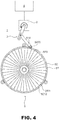
FIG. 4 is a schematic view of an engine temperature regulating device of the present invention at a state when the engine is turned on; -
FIG. 5 is a schematic view of an engine temperature regulating device of the present invention at a state when the engine is turned off; and -
FIG. 6 is a side view of an engine temperature regulating device of the present invention at a state when the engine is turned on. - The above and other objects, features and advantages of this disclosure will become apparent from the following detailed description taken with the accompanying drawings.
- With reference to
FIGS. 1 and2 for an engine temperature regulating device of the present invention, the engine temperature regulatingdevice 1 is installed to a casing with a cooled air inlet and comprises apower source 2, alink rod module 3, acontrol module 4 and afan cover module 5. Thelink rod module 3 is connected to thepower source 2, and thepower source 2 is preferably stepper motor; thecontrol module 4 is provided for detecting a temperature for starting the engine to obtain a temperature signal, and if the temperature signal is lower than a predetermined value, thepower source 2 will be controlled and driven, or if the temperature signal reaches a predetermined value, thepower source 2 will be controlled to turn off. Thefan cover module 5 is covered onto the engine cooled air inlet and comprises a fixedcasing 51 and amovable casing 52, wherein the fixedcasing 51 is formed by mounting a first surroundingmember 512 around afirst sidewall 511, and thefirst sidewall 511 has a plurality of firstair intake holes 5111 and a plurality offirst shelter plates 5112 arranged alternately with one another, and the first surroundingmember 512 has a plurality offirst ventilation holes 5121, and at least one fixing block 5122 disposed at the external periphery of the first surroundingmember 512 and capable of being secured to the casing with a cooled air inlet. Themovable casing 52 is formed by mounting a second surroundingmember 522 around asecond sidewall 521, and thesecond sidewall 521 has a plurality of secondair intake holes 5211 and a plurality ofsecond shelter plates 5212 arranged alternately with one another and the second surroundingmember 522 has a plurality ofsecond ventilation holes 5221, and apositioning block 5222 disposed at the external periphery of the second surroundingmember 522 and thelink rod module 3 is coupled to themovable casing 52. - In an embodiment of the present invention as shown in
FIG. 1 and2 , thefixed casing 51 has anopening 513, afirst bump 514 and asecond bump 515 formed at the external periphery of thefixed casing 51, and themovable casing 52 has apeg 523 configured to be corresponsive to the opening 513, so that thepeg 523 of themovable casing 52 is passed into the opening 513 of thefixed casing 51, and afastener 53 is provided for securing thepeg 523, and themovable casing 52 can be pivotally rotated in the fixedcasing 51 by using thepeg 523 as an axis, and thepositioning block 5222 of themovable casing 52 are limited and rotated between thefirst bump 514 andsecond bump 515 of the fixedcasing 51. - With reference to
FIG. 3 for a schematic view showing the initial status of the engine temperature regulating device of the present invention device, thefan cover module 5 is covered onto acooling fan 6 of the engine. When the engine is not started, thepositioning block 5222 of themovable casing 52 abuts against thesecond bump 515 of the fixedcasing 51, so that the firstair intake hole 5111 of the fixedcasing 51 and the secondair intake hole 5211 of themovable casing 52 are superimposed and defaulted to a smooth state. - After the engine is started, the
control module 4 detects an engine temperature immediately. If a detected temperature signal is lower than a predetermined value, thepower source 2 will be controlled and driven to rotate the stepper motor to pull the link rod module 3 (as shown inFIG. 4 ), so that thepositioning block 5222 linked with thelink rod module 3 is moved to abut against thefirst bump 514, and thesecond shelter plate 5212 of themovable casing 52 is covered onto the firstair intake hole 5111 of thefixed casing 51 to set the firstair intake hole 5111 to an obscured state. Now, external cold air cannot be entered into the cooled air inlet of the engine from the firstair intake hole 5111, sot that the air in the wind hood is limited to accelerate the engine warm-up process. - If the engine temperature detected by the
control module 4 reaches a predetermined value, thepower source 2 will be controlled to turn off, so that the stepper motor stops operating to resume thelink rod module 3 to its initial position (as shown inFIG. 5 ), and thepositioning block 5222 linked with thelink rod module 3 will be moved back to the position of thesecond bump 515 to superimpose the firstair intake hole 5111 of the of thefixed casing 51 and the secondair intake hole 5211 of themovable casing 52 to set them into a smooth state, and the surrounding cold air can be sucked into the air inlet continuously to assist the heat dissipation of the engine. - It is noteworthy that the first surrounding
member 512 of the fixedcasing 51 and the second surroundingmember 522 of themovable casing 52 has a plurality offirst ventilation holes 5121 and asecond ventilation hole 5221 respectively (as shown inFIG. 2 ). When thesecond shelter plate 5212 of themovable casing 52 is covered onto the firstair intake hole 5111 of the fixedcasing 51, thefirst ventilation hole 5121 of the fixedcasing 51 and thesecond ventilation hole 5221 of themovable casing 52 are not arranged alternately with one another, so as to form a hole 54 (as shown inFIG. 6 ) and prevent the air inlet of the engine from being closed completely to cause an overheat of the engine or an inconsistent heat dissipation. - Obviously, the engine temperature regulating
device 1 of the present invention has the following effects: - 1. The
device 1 of the present invention can adjust the movement of themovable casing 52 of thefan cover module 5 according to the engine operating temperature, so that when the engine is just started and situated at a cold engine stage temperature which is lower than the operating temperature, the firstair intake hole 5111 of the fixedcasing 51 is adjusted to the obscured state to stop cooled airflow to enter into the engine and reduce the time for increasing the engine temperature to its operating temperature, so as to achieve the effects of lowering the fuel consumption, reducing the waste gas discharge of the engine. When the engine reaches the operating temperature, the firstair intake hole 5111 of the fixedcasing 51 resumes its smooth state and lets cooled airflow enter into the engine to assist the heat dissipation. - 2. The first
air intake hole 5111 and secondair intake hole 5211 of thefan cover module 5 of the present invention are defaulted to the smooth state, and thus when thedevice 1 fails, thefan cover module 5 is in a closed state and the heat dissipation of the engine is affected. In addition, thefirst ventilation hole 5121 of thefixed casing 51 and thesecond ventilation hole 5221 of themovable casing 52 reserve ahole 54 when the firstair intake hole 5111 is in the obscured state, so as to prevent overheat or inconsistent heat dissipation of the engine. - In summation of the description above, the technical measure disclosed by the present invention definitely can overcome the drawbacks of the prior art and achieve the expected objectives and effects. While the invention has been described by means of specific embodiments, numerous modifications and variations could be made thereto by those skilled in the art without departing from the scope set forth in the claims.
Claims (3)
- An engine temperature regulating device (1), installed in a casing with a cooled air inlet, comprising:a power source (2);a link rod module (3), connected to the power source (2);a control module (4), for detecting a temperature for starting the engine to obtain a temperature signal, and controlling the drive of the power source (2) when the temperature signal is lower than a predetermined value or controlling and turning off the power source (2) when the temperature signal achieves the predetermined value; anda fan cover module (5), covered onto the cooled air inlet, and further comprising:a fixed casing (51), formed by mounting a first surrounding member (512) around a first sidewall (511), and the first sidewall (511) having a plurality of first air intake holes (5111) and a plurality of first shelter plates (5112) arranged alternately with one another, and disposed at a plurality of first ventilation holes (5121) of the first surrounding member (512), and at least one fixed block (5122) disposed around the external periphery of the first surrounding member (512) and capable of locking the casing with the cooled air inlet; anda movable casing (52), formed by mounting a second surrounding member (522) around a second sidewall (521), and the second sidewall (521) having a plurality of second air intake holes (5211) and a plurality of second shelter plates (5212) arranged alternately with one another, the second surrounding member (522) having a plurality of second ventilation holes (5221), and a positioning block (5222) disposed around the external periphery of the second surrounding member (522), and the link rod module (3) being coupled to the movable casing (52), and the power source (2) controlling the link rod module (3) to rotate the movable casing (52), so as to adjust the first air intake holes (5111) and the first ventilation holes (5121) of the fixed casing (51) to a smooth or obscured state, and when the first air intake holes (5111) are situated at the obscured state, the first ventilation holes (5121) still maintain holes.
- The engine temperature regulating device (1) of claim 1, wherein the fixed casing (51) has an opening (513), two bumps (514, 515) formed at the external periphery of the fixed casing (51), and the movable casing (52) has a peg (523) corresponsive to the opening (513), so that after the movable casing (52) passes the peg (523) into the opening (513) of the fixed casing (51), a fastener (53) is screwed and secured to the peg (523), and the movable casing (52) can be pivoted in the fixed casing (51) by using the peg (523) as an axis, and the positioning block (5222) is limited and moved between the two bumps (514, 515).
- The engine temperature regulating device (1) of claim 1, wherein the power source (2) is a stepper motor.
Priority Applications (1)
| Application Number | Priority Date | Filing Date | Title |
|---|---|---|---|
| EP16202296.6A EP3330511B1 (en) | 2016-12-05 | 2016-12-05 | Engine temperature regulating device |
Applications Claiming Priority (1)
| Application Number | Priority Date | Filing Date | Title |
|---|---|---|---|
| EP16202296.6A EP3330511B1 (en) | 2016-12-05 | 2016-12-05 | Engine temperature regulating device |
Publications (2)
| Publication Number | Publication Date |
|---|---|
| EP3330511A1 EP3330511A1 (en) | 2018-06-06 |
| EP3330511B1 true EP3330511B1 (en) | 2019-03-27 |
Family
ID=57539031
Family Applications (1)
| Application Number | Title | Priority Date | Filing Date |
|---|---|---|---|
| EP16202296.6A Active EP3330511B1 (en) | 2016-12-05 | 2016-12-05 | Engine temperature regulating device |
Country Status (1)
| Country | Link |
|---|---|
| EP (1) | EP3330511B1 (en) |
Family Cites Families (6)
| Publication number | Priority date | Publication date | Assignee | Title |
|---|---|---|---|---|
| DE347315C (en) * | 1919-07-29 | 1922-01-19 | Julius Friedrich Behr | Radiator arrangement on motor vehicles |
| US6142108A (en) | 1998-12-16 | 2000-11-07 | Caterpillar Inc. | Temperature control system for use with an enclosure which houses an internal combustion engine |
| JP2005042705A (en) * | 2003-07-10 | 2005-02-17 | Calsonic Kansei Corp | Air capacity control mechanism of heat exchanger |
| DE102008043006A1 (en) * | 2008-10-21 | 2010-04-22 | Robert Bosch Gmbh | Device for a radiator of a vehicle with a lamellar structure |
| TWI421405B (en) | 2011-10-25 | 2014-01-01 | Sanyang Industry Co Ltd | Locomotive engine cooling device |
| DE102013016509A1 (en) * | 2013-10-02 | 2015-04-02 | GM Global Technology Operations LLC (n. d. Ges. d. Staates Delaware) | Air flow control device for a motor vehicle radiator |
-
2016
- 2016-12-05 EP EP16202296.6A patent/EP3330511B1/en active Active
Non-Patent Citations (1)
| Title |
|---|
| None * |
Also Published As
| Publication number | Publication date |
|---|---|
| EP3330511A1 (en) | 2018-06-06 |
Similar Documents
| Publication | Publication Date | Title |
|---|---|---|
| US9701191B2 (en) | Grille shutter device | |
| BRPI0704877A (en) | internal combustion engine cooling system and method for cooling an internal combustion engine | |
| KR101171794B1 (en) | Automobile air flap opening and closing apparatus for fail safe | |
| US4469053A (en) | Automotive electric fan controlling device | |
| US10100708B2 (en) | Engine temperature regulating device | |
| CN106627105A (en) | Ventilating system for vehicle | |
| KR100232081B1 (en) | Radiator grill of an automobile | |
| EP3330511A1 (en) | Engine temperature regulating device | |
| CA2932922C (en) | Air intake structure for engine | |
| CN110214222B (en) | Cooling device for engine | |
| JPH0450209B2 (en) | ||
| JPS57119125A (en) | Cooler of automotive electronic circuit | |
| US9926831B1 (en) | Outboard motor unit and marine vessel | |
| TWI573705B (en) | Engine temperature adjustment apparatus | |
| KR20050023905A (en) | Bimetal type cooling fan controller and method thereof | |
| WO2003036078A1 (en) | Autochoke controller | |
| JP2014070593A (en) | Cooling and heating device of internal combustion engine | |
| JP3691451B2 (en) | LCD projector | |
| JPH0810657Y2 (en) | Internal combustion engine cooling system | |
| KR0119972B1 (en) | Driving unit of radiator fan | |
| JPH0450210B2 (en) | ||
| KR950005725Y1 (en) | Automatic Temperature Sensitive Air Dam Actuator for Radiator Cooling | |
| SU1257248A1 (en) | Water-cooling system for internal combustion engine | |
| KR970045642A (en) | Cooling Fan Blade Angle Adjuster | |
| KR19980060492A (en) | How to control idle speed actuator |
Legal Events
| Date | Code | Title | Description |
|---|---|---|---|
| PUAI | Public reference made under article 153(3) epc to a published international application that has entered the european phase |
Free format text: ORIGINAL CODE: 0009012 |
|
| STAA | Information on the status of an ep patent application or granted ep patent |
Free format text: STATUS: REQUEST FOR EXAMINATION WAS MADE |
|
| 17P | Request for examination filed |
Effective date: 20180131 |
|
| AK | Designated contracting states |
Kind code of ref document: A1 Designated state(s): AL AT BE BG CH CY CZ DE DK EE ES FI FR GB GR HR HU IE IS IT LI LT LU LV MC MK MT NL NO PL PT RO RS SE SI SK SM TR |
|
| AX | Request for extension of the european patent |
Extension state: BA ME |
|
| GRAP | Despatch of communication of intention to grant a patent |
Free format text: ORIGINAL CODE: EPIDOSNIGR1 |
|
| STAA | Information on the status of an ep patent application or granted ep patent |
Free format text: STATUS: GRANT OF PATENT IS INTENDED |
|
| INTG | Intention to grant announced |
Effective date: 20180731 |
|
| GRAS | Grant fee paid |
Free format text: ORIGINAL CODE: EPIDOSNIGR3 |
|
| GRAA | (expected) grant |
Free format text: ORIGINAL CODE: 0009210 |
|
| STAA | Information on the status of an ep patent application or granted ep patent |
Free format text: STATUS: THE PATENT HAS BEEN GRANTED |
|
| AK | Designated contracting states |
Kind code of ref document: B1 Designated state(s): AL AT BE BG CH CY CZ DE DK EE ES FI FR GB GR HR HU IE IS IT LI LT LU LV MC MK MT NL NO PL PT RO RS SE SI SK SM TR |
|
| REG | Reference to a national code |
Ref country code: GB Ref legal event code: FG4D |
|
| REG | Reference to a national code |
Ref country code: CH Ref legal event code: EP |
|
| REG | Reference to a national code |
Ref country code: AT Ref legal event code: REF Ref document number: 1113355 Country of ref document: AT Kind code of ref document: T Effective date: 20190415 |
|
| REG | Reference to a national code |
Ref country code: IE Ref legal event code: FG4D |
|
| REG | Reference to a national code |
Ref country code: DE Ref legal event code: R096 Ref document number: 602016011529 Country of ref document: DE |
|
| PG25 | Lapsed in a contracting state [announced via postgrant information from national office to epo] |
Ref country code: LT Free format text: LAPSE BECAUSE OF FAILURE TO SUBMIT A TRANSLATION OF THE DESCRIPTION OR TO PAY THE FEE WITHIN THE PRESCRIBED TIME-LIMIT Effective date: 20190327 Ref country code: NO Free format text: LAPSE BECAUSE OF FAILURE TO SUBMIT A TRANSLATION OF THE DESCRIPTION OR TO PAY THE FEE WITHIN THE PRESCRIBED TIME-LIMIT Effective date: 20190627 Ref country code: FI Free format text: LAPSE BECAUSE OF FAILURE TO SUBMIT A TRANSLATION OF THE DESCRIPTION OR TO PAY THE FEE WITHIN THE PRESCRIBED TIME-LIMIT Effective date: 20190327 Ref country code: SE Free format text: LAPSE BECAUSE OF FAILURE TO SUBMIT A TRANSLATION OF THE DESCRIPTION OR TO PAY THE FEE WITHIN THE PRESCRIBED TIME-LIMIT Effective date: 20190327 |
|
| REG | Reference to a national code |
Ref country code: NL Ref legal event code: MP Effective date: 20190327 |
|
| PG25 | Lapsed in a contracting state [announced via postgrant information from national office to epo] |
Ref country code: NL Free format text: LAPSE BECAUSE OF FAILURE TO SUBMIT A TRANSLATION OF THE DESCRIPTION OR TO PAY THE FEE WITHIN THE PRESCRIBED TIME-LIMIT Effective date: 20190327 Ref country code: BG Free format text: LAPSE BECAUSE OF FAILURE TO SUBMIT A TRANSLATION OF THE DESCRIPTION OR TO PAY THE FEE WITHIN THE PRESCRIBED TIME-LIMIT Effective date: 20190627 Ref country code: RS Free format text: LAPSE BECAUSE OF FAILURE TO SUBMIT A TRANSLATION OF THE DESCRIPTION OR TO PAY THE FEE WITHIN THE PRESCRIBED TIME-LIMIT Effective date: 20190327 Ref country code: LV Free format text: LAPSE BECAUSE OF FAILURE TO SUBMIT A TRANSLATION OF THE DESCRIPTION OR TO PAY THE FEE WITHIN THE PRESCRIBED TIME-LIMIT Effective date: 20190327 Ref country code: GR Free format text: LAPSE BECAUSE OF FAILURE TO SUBMIT A TRANSLATION OF THE DESCRIPTION OR TO PAY THE FEE WITHIN THE PRESCRIBED TIME-LIMIT Effective date: 20190628 Ref country code: HR Free format text: LAPSE BECAUSE OF FAILURE TO SUBMIT A TRANSLATION OF THE DESCRIPTION OR TO PAY THE FEE WITHIN THE PRESCRIBED TIME-LIMIT Effective date: 20190327 |
|
| REG | Reference to a national code |
Ref country code: AT Ref legal event code: MK05 Ref document number: 1113355 Country of ref document: AT Kind code of ref document: T Effective date: 20190327 |
|
| PG25 | Lapsed in a contracting state [announced via postgrant information from national office to epo] |
Ref country code: ES Free format text: LAPSE BECAUSE OF FAILURE TO SUBMIT A TRANSLATION OF THE DESCRIPTION OR TO PAY THE FEE WITHIN THE PRESCRIBED TIME-LIMIT Effective date: 20190327 Ref country code: PT Free format text: LAPSE BECAUSE OF FAILURE TO SUBMIT A TRANSLATION OF THE DESCRIPTION OR TO PAY THE FEE WITHIN THE PRESCRIBED TIME-LIMIT Effective date: 20190727 Ref country code: AL Free format text: LAPSE BECAUSE OF FAILURE TO SUBMIT A TRANSLATION OF THE DESCRIPTION OR TO PAY THE FEE WITHIN THE PRESCRIBED TIME-LIMIT Effective date: 20190327 Ref country code: SK Free format text: LAPSE BECAUSE OF FAILURE TO SUBMIT A TRANSLATION OF THE DESCRIPTION OR TO PAY THE FEE WITHIN THE PRESCRIBED TIME-LIMIT Effective date: 20190327 Ref country code: EE Free format text: LAPSE BECAUSE OF FAILURE TO SUBMIT A TRANSLATION OF THE DESCRIPTION OR TO PAY THE FEE WITHIN THE PRESCRIBED TIME-LIMIT Effective date: 20190327 Ref country code: RO Free format text: LAPSE BECAUSE OF FAILURE TO SUBMIT A TRANSLATION OF THE DESCRIPTION OR TO PAY THE FEE WITHIN THE PRESCRIBED TIME-LIMIT Effective date: 20190327 Ref country code: CZ Free format text: LAPSE BECAUSE OF FAILURE TO SUBMIT A TRANSLATION OF THE DESCRIPTION OR TO PAY THE FEE WITHIN THE PRESCRIBED TIME-LIMIT Effective date: 20190327 |
|
| PG25 | Lapsed in a contracting state [announced via postgrant information from national office to epo] |
Ref country code: PL Free format text: LAPSE BECAUSE OF FAILURE TO SUBMIT A TRANSLATION OF THE DESCRIPTION OR TO PAY THE FEE WITHIN THE PRESCRIBED TIME-LIMIT Effective date: 20190327 Ref country code: SM Free format text: LAPSE BECAUSE OF FAILURE TO SUBMIT A TRANSLATION OF THE DESCRIPTION OR TO PAY THE FEE WITHIN THE PRESCRIBED TIME-LIMIT Effective date: 20190327 |
|
| PG25 | Lapsed in a contracting state [announced via postgrant information from national office to epo] |
Ref country code: IS Free format text: LAPSE BECAUSE OF FAILURE TO SUBMIT A TRANSLATION OF THE DESCRIPTION OR TO PAY THE FEE WITHIN THE PRESCRIBED TIME-LIMIT Effective date: 20190727 Ref country code: AT Free format text: LAPSE BECAUSE OF FAILURE TO SUBMIT A TRANSLATION OF THE DESCRIPTION OR TO PAY THE FEE WITHIN THE PRESCRIBED TIME-LIMIT Effective date: 20190327 |
|
| REG | Reference to a national code |
Ref country code: DE Ref legal event code: R097 Ref document number: 602016011529 Country of ref document: DE |
|
| REG | Reference to a national code |
Ref country code: GB Ref legal event code: 732E Free format text: REGISTERED BETWEEN 20191212 AND 20191218 |
|
| REG | Reference to a national code |
Ref country code: DE Ref legal event code: R082 Ref document number: 602016011529 Country of ref document: DE Representative=s name: LANGPATENT ANWALTSKANZLEI IP LAW FIRM, DE Ref country code: DE Ref legal event code: R081 Ref document number: 602016011529 Country of ref document: DE Owner name: KWANG YANG MOTOR CO., LTD., TW Free format text: FORMER OWNER: SOUTHERN TAIWAN UNIVERSITY OF SCIENCE AND TECHNOLOGY, TAINAN, TW |
|
| PG25 | Lapsed in a contracting state [announced via postgrant information from national office to epo] |
Ref country code: DK Free format text: LAPSE BECAUSE OF FAILURE TO SUBMIT A TRANSLATION OF THE DESCRIPTION OR TO PAY THE FEE WITHIN THE PRESCRIBED TIME-LIMIT Effective date: 20190327 |
|
| PLBE | No opposition filed within time limit |
Free format text: ORIGINAL CODE: 0009261 |
|
| STAA | Information on the status of an ep patent application or granted ep patent |
Free format text: STATUS: NO OPPOSITION FILED WITHIN TIME LIMIT |
|
| 26N | No opposition filed |
Effective date: 20200103 |
|
| PG25 | Lapsed in a contracting state [announced via postgrant information from national office to epo] |
Ref country code: TR Free format text: LAPSE BECAUSE OF FAILURE TO SUBMIT A TRANSLATION OF THE DESCRIPTION OR TO PAY THE FEE WITHIN THE PRESCRIBED TIME-LIMIT Effective date: 20190327 |
|
| REG | Reference to a national code |
Ref country code: CH Ref legal event code: PL |
|
| REG | Reference to a national code |
Ref country code: BE Ref legal event code: MM Effective date: 20191231 |
|
| PG25 | Lapsed in a contracting state [announced via postgrant information from national office to epo] |
Ref country code: MC Free format text: LAPSE BECAUSE OF FAILURE TO SUBMIT A TRANSLATION OF THE DESCRIPTION OR TO PAY THE FEE WITHIN THE PRESCRIBED TIME-LIMIT Effective date: 20190327 |
|
| PG25 | Lapsed in a contracting state [announced via postgrant information from national office to epo] |
Ref country code: FR Free format text: LAPSE BECAUSE OF NON-PAYMENT OF DUE FEES Effective date: 20191231 Ref country code: IE Free format text: LAPSE BECAUSE OF NON-PAYMENT OF DUE FEES Effective date: 20191205 Ref country code: LU Free format text: LAPSE BECAUSE OF NON-PAYMENT OF DUE FEES Effective date: 20191205 |
|
| PG25 | Lapsed in a contracting state [announced via postgrant information from national office to epo] |
Ref country code: LI Free format text: LAPSE BECAUSE OF NON-PAYMENT OF DUE FEES Effective date: 20191231 Ref country code: CH Free format text: LAPSE BECAUSE OF NON-PAYMENT OF DUE FEES Effective date: 20191231 Ref country code: BE Free format text: LAPSE BECAUSE OF NON-PAYMENT OF DUE FEES Effective date: 20191231 |
|
| PG25 | Lapsed in a contracting state [announced via postgrant information from national office to epo] |
Ref country code: CY Free format text: LAPSE BECAUSE OF FAILURE TO SUBMIT A TRANSLATION OF THE DESCRIPTION OR TO PAY THE FEE WITHIN THE PRESCRIBED TIME-LIMIT Effective date: 20190327 |
|
| PG25 | Lapsed in a contracting state [announced via postgrant information from national office to epo] |
Ref country code: MT Free format text: LAPSE BECAUSE OF FAILURE TO SUBMIT A TRANSLATION OF THE DESCRIPTION OR TO PAY THE FEE WITHIN THE PRESCRIBED TIME-LIMIT Effective date: 20190327 Ref country code: HU Free format text: LAPSE BECAUSE OF FAILURE TO SUBMIT A TRANSLATION OF THE DESCRIPTION OR TO PAY THE FEE WITHIN THE PRESCRIBED TIME-LIMIT; INVALID AB INITIO Effective date: 20161205 |
|
| PG25 | Lapsed in a contracting state [announced via postgrant information from national office to epo] |
Ref country code: SI Free format text: LAPSE BECAUSE OF FAILURE TO SUBMIT A TRANSLATION OF THE DESCRIPTION OR TO PAY THE FEE WITHIN THE PRESCRIBED TIME-LIMIT Effective date: 20190327 |
|
| PG25 | Lapsed in a contracting state [announced via postgrant information from national office to epo] |
Ref country code: MK Free format text: LAPSE BECAUSE OF FAILURE TO SUBMIT A TRANSLATION OF THE DESCRIPTION OR TO PAY THE FEE WITHIN THE PRESCRIBED TIME-LIMIT Effective date: 20190327 |
|
| PGFP | Annual fee paid to national office [announced via postgrant information from national office to epo] |
Ref country code: IT Payment date: 20250205 Year of fee payment: 10 |
|
| PGFP | Annual fee paid to national office [announced via postgrant information from national office to epo] |
Ref country code: DE Payment date: 20250212 Year of fee payment: 10 |
|
| PGFP | Annual fee paid to national office [announced via postgrant information from national office to epo] |
Ref country code: GB Payment date: 20251001 Year of fee payment: 10 |